


Maintenance and Service
Guide
HP Compaq tc1100 Tablet PC
Document Part Number: 335572-003
November 2004
This guide is a troubleshooting reference used for maintaining
and servicing the tablet PC. It provides comprehensive
information on identifying tablet PC features, components, and
spare parts, troubleshooting tablet PC problems, and performing
tablet PC disassembly procedures.

© Copyright 2004 Hewlett-Packard Development Company, L.P.
Microsoft and Windows are U.S. registered trademarks of Microsoft
Corporation. Intel, Pentium, and Celeron are trademarks or registered
trademarks of Intel Corporation or its subsidiaries in the United States and
other countries. SD Logo is a trademark of its proprietor. Bluetooth is a
trademark owned by its proprietor and used by Hewlett-Packard Company
under license.
The information contained herein is subject to change without notice. The
only warranties for HP products and services are set forth in the express
warranty statements accompanying such products and services. Nothing
herein should be construed as constituting an additional warranty. HP shall
not be liable for technical or editorial errors or omissions contained herein.
Maintenance and Service Guide
HP Compaq tc1100 Tablet PC
Third Edition November 2004
Second Edition June 2004
First Edition February 2004
Document Part Number: 335572-003

Contents
1 Product Description
1.1 Models. . . . . . . . . . . . . . . . . . . . . . . . . . . . . . . . . . . . 1–3
1.2 Features . . . . . . . . . . . . . . . . . . . . . . . . . . . . . . . . . . 1–48
1.3 Clearing a Password . . . . . . . . . . . . . . . . . . . . . . . . 1–50
1.4 Power Management. . . . . . . . . . . . . . . . . . . . . . . . . 1–51
1.5 Tablet PC External Components. . . . . . . . . . . . . . . 1–52
1.6 Keyboard Components . . . . . . . . . . . . . . . . . . . . . . 1–65
1.7 HP Tablet PC Docking Station Components . . . . . 1–70
1.8 Design Overview. . . . . . . . . . . . . . . . . . . . . . . . . . . 1–74
2 Troubleshooting
2.1 Setup and Diagnostics Utilities . . . . . . . . . . . . . . . . . 2–2
Selecting Setup or HP Diagnostics . . . . . . . . . . . . . . 2–2
Selecting from the File Menu . . . . . . . . . . . . . . . . . . 2–3
Selecting from the Security Menu. . . . . . . . . . . . . . . 2–4
Selecting from the Advanced Menu . . . . . . . . . . . . . 2–6
2.2 Using HP Diagnostics for Windows . . . . . . . . . . . . . 2–8
Obtaining, Saving, or Printing
Configuration Information . . . . . . . . . . . . . . . . . . . . 2–8
Obtaining, Saving or Printing Diagnostic Test
Information . . . . . . . . . . . . . . . . . . . . . . . . . . . . . . . . 2–9
Troubleshooting Flowcharts . . . . . . . . . . . . . . . . . . 2–11
Flowchart 2.1—Initial Troubleshooting . . . . . . . . . 2–12
Flowchart 2.2—No Power, Part 1 . . . . . . . . . . . . . . 2–13
Flowchart 2.3—No Power, Part 2 . . . . . . . . . . . . . . 2–14
Flowchart 2.4—No Power, Part 3 . . . . . . . . . . . . . . 2–15
Maintenance and Service Guide iii

Contents
Flowchart 2.5—No Power, Part 4 . . . . . . . . . . . . . . 2–16
Flowchart 2.6—No Video, Part 1 . . . . . . . . . . . . . . 2–17
Flowchart 2.7—No Video, Part 2 . . . . . . . . . . . . . . 2–18
Flowchart 2.8—Nonfunctioning Docking Station
(if applicable) . . . . . . . . . . . . . . . . . . . . . . . . . . . . . 2–19
Flowchart 2.9—No Operating System (OS)
Loading . . . . . . . . . . . . . . . . . . . . . . . . . . . . . . . . . . 2–20
Flowchart 2.10—No OS Loading from
Hard Drive, Part 1 . . . . . . . . . . . . . . . . . . . . . . . . . . 2–21
Flowchart 2.11—No OS Loading from
Hard Drive, Part 2 . . . . . . . . . . . . . . . . . . . . . . . . . . 2–22
Flowchart 2.12—No OS Loading from
Hard Drive, Part 3 . . . . . . . . . . . . . . . . . . . . . . . . . . 2–23
Flowchart 2.13—No OS Loading from
Diskette Drive . . . . . . . . . . . . . . . . . . . . . . . . . . . . . 2–24
Flowchart 2.14—No OS Loading from
CD-ROM or DVD-ROM Drive . . . . . . . . . . . . . . . 2–25
Flowchart 2.15—No Audio, Part 1 . . . . . . . . . . . . . 2–26
Flowchart 2.16—No Audio, Part 2 . . . . . . . . . . . . . 2–27
Flowchart 2.17—Nonfunctioning Device . . . . . . . . 2–28
Flowchart 2.18—Nonfunctioning Keyboard. . . . . . 2–29
Flowchart 2.19—Nonfunctioning
Pointing Device . . . . . . . . . . . . . . . . . . . . . . . . . . . . 2–30
Flowchart 2.20—No Network or
Modem Connection . . . . . . . . . . . . . . . . . . . . . . . . . 2–31
3 Illustrated Parts Catalog
3.1 Serial Number Location . . . . . . . . . . . . . . . . . . . . . . 3–1
3.2 HP Compaq Tablet PC System
Major Components. . . . . . . . . . . . . . . . . . . . . . . . . . 3–2
3.3 Miscellaneous Cable Kit Components . . . . . . . . . . . 3–6
3.4 Miscellaneous Plastics/Hardware
Kit Components . . . . . . . . . . . . . . . . . . . . . . . . . . . . 3–7
3.5 Keyboard. . . . . . . . . . . . . . . . . . . . . . . . . . . . . . . . . . 3–8
3.6 Optional HP Tablet PC Docking Station . . . . . . . . 3–10
iv Maintenance and Service Guide

Contents
3.7 HP Tablet PC Docking Station Components . . . . . 3–11
3.8 Miscellaneous . . . . . . . . . . . . . . . . . . . . . . . . . . . . . 3–13
3.9 Sequential Part Number Listing . . . . . . . . . . . . . . . 3–14
4 Removal and Replacement Preliminaries
4.1 Tools Required . . . . . . . . . . . . . . . . . . . . . . . . . . . . . 4–1
4.2 Service Considerations . . . . . . . . . . . . . . . . . . . . . . . 4–1
Plastic Parts . . . . . . . . . . . . . . . . . . . . . . . . . . . . . . . . 4–2
Cables and Connectors . . . . . . . . . . . . . . . . . . . . . . . 4–2
4.3 Preventing Damage to Removable Drives . . . . . . . . 4–2
4.4 Preventing Electrostatic Damage . . . . . . . . . . . . . . . 4–3
4.5 Packaging and Transporting Equipment . . . . . . . . . . 4–4
4.6 Workstation Precautions . . . . . . . . . . . . . . . . . . . . . . 4–4
4.7 Grounding Equipment and Methods . . . . . . . . . . . . . 4–5
5 Removal and Replacement Procedures
5.1 Serial Number . . . . . . . . . . . . . . . . . . . . . . . . . . . . . . 5–2
5.2 Disassembly Sequence Chart . . . . . . . . . . . . . . . . . . 5–3
5.3 Preparing the Tablet PC for Disassembly . . . . . . . . . 5–4
Before You Begin . . . . . . . . . . . . . . . . . . . . . . . . . . . 5–4
5.4 Real Time Clock Battery. . . . . . . . . . . . . . . . . . . . . 5–12
5.5 Hard Drive. . . . . . . . . . . . . . . . . . . . . . . . . . . . . . . . 5–13
5.6 Display Panel Assembly . . . . . . . . . . . . . . . . . . . . . 5–16
5.7 System Board . . . . . . . . . . . . . . . . . . . . . . . . . . . . . 5–25
5.8 Fan and Heat Sink . . . . . . . . . . . . . . . . . . . . . . . . . . 5–35
5.9 Optional HP Tablet PC Docking Station . . . . . . . . 5–37
Maintenance and Service Guide v

Contents
6 Specifications
A Connector Pin Assignments
B Power Cord Set Requirements
C Screw Listing
Index
vi Maintenance and Service Guide
1
Product Description
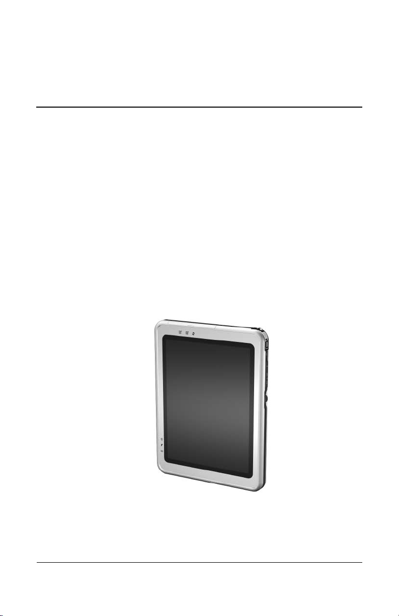
Depending on model, the HP Compaq tc1100 Tablet PC offers a
1.1-GHz Intel® Pentium® M or 900-MHz Ultra Low Voltage
Mobile Intel Celeron® processor with 512-KB cache, a 10.4-inch
color TFT XGA display, up to 2 GB of 333-MHz DDR SDRAM,
and NVIDIA GeForce4 420 Go 4X AGP graphics with 32 MB of
video DDR SDRAM.
The primary pointing device on the tablet PC is the tablet PC pen.
Handwriting recognition software is available in
Microsoft® Windows® XP Tablet PC Edition 2005, the
operating system installed on the tablet PC.
HP Compaq tc1100 Tablet PC
Maintenance and Service Guide 1–1
Product Description
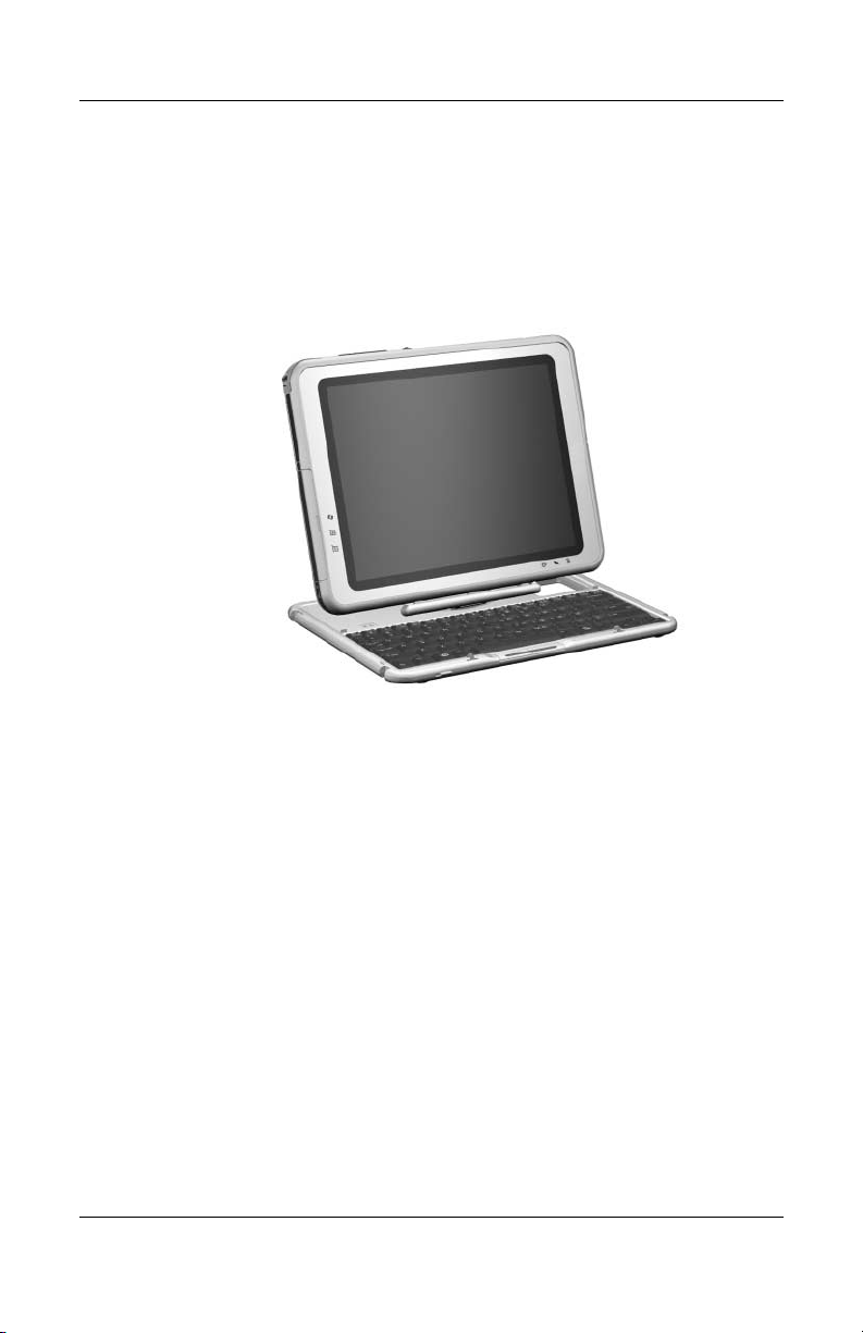
The optional keyboard is slightly smaller than a full-size
notebook keyboard and it provides 101 data entry keys, cursor
control keys, and a pointing stick device.
The optional HP Tablet PC Docking Station (not shown) provides
access to a MultiBay and a variety of connectors.
HP Compaq tc1100 Tablet PC with Optional Keyboard
1–2 Maintenance and Service Guide

Product Description
1.1 Models
Tablet PC models are shown in Tables 1-1 through 1-66.
Table 1 -1
HP Compaq tc1100 Tablet PC
Naming Conventions
Key
CTC1100 QP 100 X0 30 N Ci 25 T XXXXXX-XXX
123456789 10
Key Description Options
1 Brand/Series
designator
2 Processor type QP = Intel 1.0-GHz or 1.1-GHz Pentium M
3 Processor speed 110 = 1.1 GHz
4Display type/
size/resolution
5 Hard drive size 30 = 30 GB
6 Optical drive
designator
C = Compaq TC1100 = Tablet PC
QC = Intel 800-MHz or 900-MHz Celeron
T = configure-to-order
100 = 1.0 GHz
900 = 900 MHz
800 = 800 MHz
X = XGA (1024 × 768) 0 = 10.4-inch
40 = 40 GB
60 = 60 GB
80 = 80 GB
C = 24x CD-ROM
N = no optical drive
V = 24x DVD/CD-RW Combo Drive
W = 8x DVD/CD-RW Combo Drive
Maintenance and Service Guide 1–3

Product Description
Table 1 -1
HP Compaq tc1100 Tablet PC
Naming Conventions
Key
CTC1100 QP 100 X0 30 N Ci 25 T XXXXXX-XXX
123456789 10
Key Description Options
(Continued)
7 Integrated
communication
8 RAM 25 = 256 MB
9 Operating system T = Microsoft Windows XP Pro Tablet PC
Cb = Combination modem/NIC/802.11b wireless
LAN (Intel)
Cd = Combination modem/NIC/802.11a/b/g
wireless LAN (Intel)
Cf = Combination modem/NIC/802.11b/g
wireless LAN (Intel)/Bluetooth
Ci = combination modem/NIC/802.11b wireless
LAN (Intel)/Bluetooth wireless PAN
Cj = Combination modem/NIC/802.11b/g
wireless LAN (Intel)/Bluetooth wireless PAN
Ck = Combination modem/NIC/802.11b wireless
LAN (Intel)/Bluetooth wireless PAN
Cm = combination modem/NIC/802.11 a/b/g
wireless LAN Japan/Bluetooth wireless PAN
CN = combination modem/NIC
Nk = combination modem/NIC/802.11 a/b/g
wireless LAN/Bluetooth wireless PAN
51 = 512 MB
76 = 768 MB
10 = 1 GB
Edition 2005
® wireless PAN
1–4 Maintenance and Service Guide

Product Description
Table 1-2
HP Compaq tc1100 Tablet PC Models
The following HP Compaq tc1100 Tablet PC models feature:
■ Intel 1.0-GHz Pentium M processor
■ 512-MB RAM
■ Combination modem/NIC/wireless LAN (Intel)
■ 40-GB hard drive
■ Digital pen and pointing stick keyboard
■ 6-cell, 3.6-Ah lithium ion (Li-Ion) battery pack
■ 32 MB of discrete video memory
■ 3-year warranty on parts and labor
CTC1100 QP 100 X0 40 N Ci 51 T
Asia Pacific
Australia
Belgium
Brazil
China
Denmark
Europe International
France
French Canada
Germany
Italy
Japan
Japan (English)
DQ871A#UUF
DQ871A#ABG
DQ871A#UUG
DQ871A#AC4
DQ871A#AB2
DQ871A#ABY
DQ871A#ABB
DQ871A#ABF
DQ871A#ABC
DQ871A#ABD
DQ871A#ABZ
DQ871A#ABJ
DQ871A#ACF
Korea
Latin America
Norway
Russia
Spain
Sweden/Finland
Switzerland
Ta i wa n
United Kingdom
United States
DQ871A#AB1
DQ990A#ABM
DQ871A#ABN
DQ871A#ACB
DQ871A#ABE
DQ871A#AK8
DQ871A#B12
DQ871A#AB0
DQ871A#ABU
DQ871A#ABA
Maintenance and Service Guide 1–5
Product Description
Tabl e 1-3
HP Compaq tc1100 Tablet PC Models
The following HP Compaq tc1100 Tablet PC models feature:
■ Intel 1.0-GHz Pentium M processor
■ 512-MB RAM
■ Combination modem/NIC
■ 40 GB hard drive
■ Digital pen and pointing stick keyboard
■ 6-cell, 3.6-Ah Li-Ion battery pack
■ 32 MB of discrete video memory
■ 3-year warranty on parts and labor
CTC1100 QP 100 X0 40 N CN 51 T
Asia Pacific
Australia
Belgium
China
Denmark
Europe International
France
French Canada
Germany
Italy
Japan
Japan (English)
DQ872A#UUF
DQ872A#ABG
DQ872A#UUG
DQ872A#AB2
DQ872A#ABY
DQ872A#ABB
DQ872A#ABF
DQ872A#ABC
DQ872A#ABD
DQ872A#ABZ
DQ872A#ABJ
DQ872A#ACF
Korea
Latin America
Norway
Spain
Sweden/Finland
Switzerland
Ta i wa n
United Kingdom
United States
DQ872A#AB1
DQ872A#ABM
DQ872A#ABN
DQ872A#ABE
DQ872A#AK8
DQ872A#B12
DQ872A#AB0
DQ872A#ABU
DQ872A#ABA
1–6 Maintenance and Service Guide
Product Description
Tabl e 1-4
HP Compaq tc1100 Tablet PC Models
The following HP Compaq tc1100 Tablet PC models feature:
■ Intel 800-MHz (Celeron) processor
■ 256-MB RAM
■ Combination modem/NIC/wireless LAN (Intel)
■ 30-GB hard drive
■ Digital pen and pointing stick keyboard
■ 6-cell, 3.6-Ah Li-Ion battery pack
■ 32 MB of discrete video memory
■ 1-year warranty on parts and labor
CTC1100 QC 800 x0 30 N Ci 25 T
Asia Pacific
Australia
Belgium
Brazil
China
Denmark
Europe International
France
French Canada
Germany
Italy
Japan
Japan (English)
DQ873A#UUF
DQ873A#ABG
DQ873A#UUG
DQ873A#AC4
DQ873A#AB2
DQ873A#ABY
DQ873A#ABB
DQ873A#ABF
DQ873A#ABC
DQ873A#ABD
DQ873A#ABZ
DQ872A#ABJ
DQ872A#ACF
Korea
Latin America
Norway
Russia
Spain
Sweden/Finland
Switzerland
Ta i wa n
United Kingdom
United States
DQ872A#AB1
DQ873A#ABM
DQ872A#ABN
DQ873A#ACB
DQ872A#ABE
DQ872A#AK8
DQ872A#B12
DQ872A#AB0
DQ872A#ABU
DQ872A#ABA
Maintenance and Service Guide 1–7

Product Description
Tabl e 1-5
HP Compaq tc1100 Tablet PC Models
The following HP Compaq tc1100 Tablet PC models feature:
■ Intel 800-MHz (Celeron) processor
■ 512-MB RAM
■ Combination modem/NIC/wireless LAN
■ 60-GB hard drive
■ Digital pen and pointing stick keyboard
■ 6-cell, 3.6-Ah Li-Ion battery pack
■ 32 MB of discrete video memory
■ 1-year warranty on parts and labor
CTC1100 QC 800 X0 60 N Cm 51 T
Japan DQ989A#ABJ Japan (English) DQ989A#ACF
1–8 Maintenance and Service Guide

Product Description
Tabl e 1-6
HP Compaq tc1100 Tablet PC Models
The following HP Compaq tc1100 Tablet PC models feature:
■ Intel 1.0-GHz Pentium M processor
■ 512-MB RAM
■ Combination modem/NIC/wireless LAN (Intel)
■ 40-GB hard drive
■ Digital pen and pointing stick keyboard
■ 6-cell, 3.6-Ah Li-Ion battery pack
■ 32 MB of discrete video memory
■ 3-year warranty on parts and labor
CTC1100 QP 100 X0 40 N Ci 51 T
Asia Pacific
Australia
Belgium
Brazil
China
Denmark
Europe International
France
French Canada
Germany
Italy
Japan
Japan (English)
DQ873A#UUF
DQ873A#ABG
DQ873A#UUG
DQ873A#AC4
DQ873A#AB2
DQ873A#ABY
DQ873A#ABB
DQ873A#ABF
DQ873A#ABC
DQ873A#ABD
DQ873A#ABZ
DQ872A#ABJ
DQ872A#ACF
Korea
Latin America
Norway
Spain
Sweden/Finland
Switzerland
Ta i wa n
United Kingdom
United States
DQ872A#AB1
DQ873A#ABM
DQ872A#ABN
DQ872A#ABE
DQ872A#AK8
DQ872A#B12
DQ872A#AB0
DQ872A#ABU
DQ872A#ABA
Maintenance and Service Guide 1–9

Product Description
Tabl e 1-7
HP Compaq tc1100 Tablet PC Models
The following HP Compaq tc1100 Tablet PC models feature:
■ Intel 1.0-GHz Pentium M processor
■ 512-MB RAM
■ Combination modem/NIC/wireless LAN
■ 40-GB hard drive
■ Digital pen and pointing stick keyboard
■ 6-cell, 3.6-Ah Li-Ion battery pack
■ 32 MB of discrete video memory
■ 3-year warranty on parts and labor
CTC1100 QP 100 X0 40 N Cm 51 T
Asia Pacific
Australia
Belgium
Brazil
China
Denmark
Europe International
France
French Canada
Germany
Italy
Japan
PF292AA#UUF
PF292AA#ABG
PF292AA#UUG
PF292AA#AC4
PF292AA#AB2
PF292AA#ABY
PF292AA#ABB
PF292AA#ABF
PF292AA#ABC
PF292AA#ABD
PF292AA#ABZ
PF292AA#ABJ
Japan (English)
Korea
Latin America
Norway
Russia
Spain
Sweden/Finland
Switzerland
Ta i wa n
United Kingdom
United States
PF292AA#ACF
PF292AA#AB1
PF292AA#ABM
PF292AA#ABN
PF292AA#ACB
PF292AA#ABE
PF292AA#AK8
PF292AA#B12
PF292AA#AB0
PF292AA#ABU
PF292AA#ABA
1–10 Maintenance and Service Guide

Product Description
Tabl e 1-8
HP Compaq tc1100 Tablet PC Models
The following HP Compaq tc1100 Tablet PC models feature:
■ Intel 1.0-GHz Pentium M processor
■ 512-MB RAM
■ Combination modem/NIC/wireless LAN (Intel)
■ 80-GB hard drive
■ Digital pen and pointing stick keyboard
■ 6-cell, 3.6-Ah Li-Ion battery pack
■ 32 MB of discrete video memory
■ 3-year warranty on parts and labor
CTC1100 QP 100 X0 80 N Ci 51 T
Brazil PD370L#AC4
Table 1 -9
HP Compaq tc1100 Tablet PC Models
The following HP Compaq tc1100 Tablet PC models feature:
■ Intel 1.0-GHz Pentium M processor
■ 256-MB RAM
■ Combination modem/NIC/wireless LAN (Intel)
■ 40-GB hard drive
■ Digital pen and pointing stick keyboard
■ 6-cell, 3.6-Ah Li-Ion battery pack
■ 32 MB of discrete video memory
■ 3-year warranty on parts and labor
CTC1100 QP 100 X0 40 N Ci 25 T
China PE757PA#AB2
Maintenance and Service Guide 1–11

Product Description
Table 1-10
HP Compaq tc1100 Tablet PC Models
The following HP Compaq tc1100 Tablet PC models feature:
■ Intel 1.0-GHz Pentium M processor
■ 256-MB RAM
■ Combination modem/NIC/wireless LAN (Intel)
■ 30-GB hard drive
■ Digital pen and pointing stick keyboard
■ 6-cell, 3.6-Ah Li-Ion battery pack
■ 32 MB of discrete video memory
■ 1-year warranty on parts and labor
CTC1100 QP 100 X0 30 N Ci 25 T
Asia Pacific PE788PS#UUF
Table 1-11
HP Compaq tc1100 Tablet PC Models
The following HP Compaq tc1100 Tablet PC models feature:
■ Intel 1.0-GHz Pentium M processor
■ 256-MB RAM
■ Combination modem/NIC/wireless LAN (Intel)
■ 30-GB hard drive
■ DVD/CD-RW Combo Drive
■ USB MulitBay Cradle
■ Digital pen and pointing stick keyboard
■ 6-cell, 3.6-Ah Li-Ion battery pack
■ 32 MB of discrete video memory
■ 1-year warranty on parts and labor
CTC1100 QP 100 X0 30 Y Ci 25 T
Asia Pacific PE739PA#UUF
1–12 Maintenance and Service Guide

Product Description
Table 1-12
HP Compaq tc1100 Tablet PC Models
The following HP Compaq tc1100 Tablet PC models feature:
■ Intel 1.0-GHz Pentium M processor
■ 256-MB RAM
■ Combination modem/NIC/wireless LAN (Intel)
■ 40 GB hard drive
■ Digital pen and pointing stick keyboard
■ 6-cell, 3.6-Ah Li-Ion battery pack
■ 32 MB of discrete video memory
■ 3-year warranty on parts and labor
CTC1100 QP 100 X0 40 N Ci 25 T
United States PD540UC#ABA
Table 1-13
HP Compaq tc1100 Tablet PC Models
The following HP Compaq tc1100 Tablet PC models feature:
■ Intel 1.0-GHz Pentium M processor
■ 256-MB RAM
■ Combination modem/NIC/wireless LAN (Intel)
■ 40-GB hard drive
■ Digital pen and pointing stick keyboard
■ 6-cell, 3.6-Ah Li-Ion battery pack
■ 32 MB of discrete video memory
■ 1-year warranty on parts and labor
CTC1100 QP 100 X0 40 N Ci 25 T
Taiwan PC966PS#AB0
Maintenance and Service Guide 1–13

Product Description
Table 1-14
HP Compaq tc1100 Tablet PC Models
The following HP Compaq tc1100 Tablet PC models feature:
■ Intel 1.0-GHz Pentium M processor
■ 512-MB RAM
■ Combination modem/NIC/wireless LAN (Intel)
■ 40-GB hard drive
■ Digital pen and pointing stick keyboard
■ 6-cell, 3.6-Ah Li-Ion battery pack
■ 32 MB of discrete video memory
■ 3-year warranty on parts and labor
CTC1100 QP 100 X0 40 N Ci 51 T
United States PC955US#ABA
Table 1-15
HP Compaq tc1100 Tablet PC Models
The following HP Compaq tc1100 Tablet PC models feature:
■ Intel 1.0-GHz Pentium M processor
■ 256-MB RAM
■ Combination modem/NIC/wireless LAN (Intel)
■ 30-GB hard drive
■ 8X DVD-ROM drive
■ USB MultiBay cradle
■ Digital pen and pointing stick keyboard
■ 6-cell, 3.6-Ah Li-Ion battery pack
■ 32 MB of discrete video memory
■ 1-year warranty on parts and labor
CTC1100 QP 100 X0 30 Y Ci 25 T
Taiwan PC962PS#AB0
1–14 Maintenance and Service Guide

Product Description
Table 1-16
HP Compaq tc1100 Tablet PC Models
The following HP Compaq tc1100 Tablet PC models feature:
■ Intel 1.0-GHz Pentium M processor
■ 512-MB RAM
■ Combination modem/NIC/wireless LAN (Intel)
■ 40-GB hard drive
■ 24X DVD/CD-RW combo drive
■ USB MultiBay cradle
■ Digital pen and pointing stick keyboard
■ 6-cell, 3.6-Ah Li-Ion battery pack
■ 32 MB of discrete video memory
■ 3-year warranty on parts and labor
CTC1100 QP 100 X0 40 Y Ci 51 T
Asia Pacific PB719PA#UUF
Table 1-17
HP Compaq tc1100 Tablet PC Models
The following HP Compaq tc1100 Tablet PC models feature:
■ Intel 1.0-GHz Pentium M processor
■ 512-MB RAM
■ Combination modem/NIC/wireless LAN (Intel)
■ 80-GB hard drive
■ Digital pen and pointing stick keyboard
■ 6-cell, 3.6-Ah Li-Ion battery pack
■ 32 MB of discrete video memory
■ 3-year warranty on parts and labor
CTC1100 QP 100 X0 80 N Ci 51 T
United States PC317US#ABA
Maintenance and Service Guide 1–15

Product Description
Table 1-18
HP Compaq tc1100 Tablet PC Models
The following HP Compaq tc1100 Tablet PC models feature:
■ Intel 1.0-GHz Pentium M processor
■ 512-MB RAM
■ Combination modem/NIC/wireless LAN (Intel)
■ 60-GB hard drive
■ Digital pen and pointing stick keyboard
■ 6-cell, 3.6-Ah Li-Ion battery pack
■ 32 MB of discrete video memory
■ 3-year warranty on parts and labor
CTC1100 QP 100 X0 60 N Ci 51 T
United States PC318US#ABA
Table 1-19
HP Compaq tc1100 Tablet PC Models
The following HP Compaq tc1100 Tablet PC models feature:
■ Intel 1.0-GHz Pentium M processor
■ 512-MB RAM
■ Combination modem/NIC/wireless LAN (Intel)
■ 60-GB hard drive
■ 24X DVD/CD-RW combo drive
■ USB MultiBay cradle
■ Digital pen and pointing stick keyboard
■ 6-cell, 3.6-Ah Li-Ion battery pack
■ 32 MB of discrete video memory
■ 3-year warranty on parts and labor
CTC1100 QP 100 X0 60 Y Ci 51 T
United States PC316US#ABA
1–16 Maintenance and Service Guide

Product Description
Table 1-20
HP Compaq tc1100 Tablet PC Models
The following HP Compaq tc1100 Tablet PC models feature:
■ Intel 1.0-GHz Pentium M processor
■ 256-MB RAM
■ Combination modem/NIC/wireless LAN (Intel)
■ 40-GB hard drive
■ Digital pen and pointing stick keyboard
■ 6-cell, 3.6-Ah Li-Ion battery pack
■ 32 MB of discrete video memory
■ 1-year warranty on parts and labor
CTC1100 QP 100 X0 40 N Ci 25 T
Asia Pacific PB486PS#UUF
Table 1-21
HP Compaq tc1100 Tablet PC Models
The following HP Compaq tc1100 Tablet PC models feature:
■ Intel 1.0-GHz Pentium M processor
■ 512-MB RAM
■ Combination modem/NIC/wireless LAN (Intel)
■ 60-GB hard drive
■ Digital pen and pointing stick keyboard
■ 6-cell, 3.6-Ah Li-Ion battery pack
■ 32 MB of discrete video memory
■ 3-year warranty on parts and labor
CTC1100 QP 100 X0 60 N Ci 51 T
Japan (English) PA605PA#ACF
Maintenance and Service Guide 1–17

Product Description
Table 1-22
HP Compaq tc1100 Tablet PC Models
The following HP Compaq tc1100 Tablet PC models feature:
■ Intel 1.0-GHz Pentium M processor
■ 768-MB RAM
■ Combination modem/NIC/wireless LAN (Intel)
■ 60-GB hard drive
■ 8X DVD-ROM drive
■ Tablet dock
■ USB mouse
■ Digital pen and pointing stick keyboard
■ 6-cell, 3.6-Ah Li-Ion battery pack
■ 32 MB of discrete video memory
■ 3-year warranty on parts and labor
CTC1100 QP 100 X0 60 Y Ci 76 T
Japan PA604PA#ABJ
Table 1-23
HP Compaq tc1100 Tablet PC Models
The following HP Compaq tc1100 Tablet PC models feature:
■ Intel 1.0-GHz Pentium M processor
■ 512-MB RAM
■ Combination modem/NIC/wireless LAN (Intel)
■ 40-GB hard drive
■ Digital pen and pointing stick keyboard
■ 6-cell, 3.6-Ah Li-Ion battery pack
■ 32 MB of discrete video memory
■ 3-year warranty on parts and labor
CTC1100 QP 100 X0 40 N Ci 51 T
United States DZ937US#ABA
1–18 Maintenance and Service Guide

Product Description
Table 1-24
HP Compaq tc1100 Tablet PC Models
The following HP Compaq tc1100 Tablet PC models feature:
■ Intel 1.0-GHz Pentium M processor
■ 768-MB RAM
■ Combination modem/NIC/wireless LAN (Intel)
■ 60-GB hard drive
■ 8X DVD-ROM drive
■ Tablet dock
■ USB mouse
■ Digital pen and pointing stick keyboard
■ 6-cell, 3.6-Ah Li-Ion battery pack
■ 32 MB of discrete video memory
■ 1-year warranty on parts and labor
CTC1100 QP 100 X0 60 Y Ci 76 T
Japan DY861PA#ABJ
Table 1-25
HP Compaq tc1100 Tablet PC Models
The following HP Compaq tc1100 Tablet PC models feature:
■ Intel 1.0-GHz Pentium M processor
■ 1-GB RAM
■ Combination modem/NIC/wireless LAN (Intel)
■ 40-GB hard drive
■ Digital pen and pointing stick keyboard
■ 6-cell, 3.6-Ah Li-Ion battery pack
■ 32 MB of discrete video memory
■ 3-year warranty on parts and labor
CTC1100 QP 100 X0 40 N Ci 10 T
China DX381P#AB2
Maintenance and Service Guide 1–19

Product Description
Table 1-26
HP Compaq tc1100 Tablet PC Models
The following HP Compaq tc1100 Tablet PC models feature:
■ Intel 1.0-GHz Pentium M processor
■ 256-MB RAM
■ Combination modem/NIC/wireless LAN (Intel)
■ 40-GB hard drive
■ Digital pen and pointing stick keyboard
■ 6-cell, 3.6-Ah Li-Ion battery pack
■ 32 MB of discrete video memory
■ 1-year warranty on parts and labor
CTC1100 QP 100 X0 40 N Ci 25 T
Asia Pacific DX993PC#UUF
Table 1-27
HP Compaq tc1100 Tablet PC Models
The following HP Compaq tc1100 Tablet PC models feature:
■ Intel 1.0-GHz Pentium M processor
■ 512-MB RAM
■ Combination modem/NIC/wireless LAN (Intel)
■ 60-GB hard drive
■ Digital pen and pointing stick keyboard
■ 6-cell, 3.6-Ah Li-Ion battery pack
■ 32 MB of discrete video memory
■ 3-year warranty on parts and labor
CTC1100 QP 100 X0 60 N Ci 51 T
Asia Pacific DX382P#UUF
1–20 Maintenance and Service Guide

Product Description
Table 1-28
HP Compaq tc1100 Tablet PC Models
The following HP Compaq tc1100 Tablet PC models feature:
■ Intel 1.0-GHz Pentium M processor
■ 512-MB RAM
■ Combination modem/NIC/wireless LAN (Intel)
■ 40-GB hard drive
■ Digital pen and pointing stick keyboard
■ 6-cell, 3.6-Ah Li-Ion battery pack
■ 32 MB of discrete video memory
■ 3-year warranty on parts and labor
CTC1100 QP 100 X0 40 N Ci 51 T
United States DX867S#ABA
Table 1-29
HP Compaq tc1100 Tablet PC Models
The following HP Compaq tc1100 Tablet PC models feature:
■ Intel 1.0-GHz Pentium M processor
■ 256-MB RAM
■ Combination modem/NIC/wireless LAN (Intel)
■ 30-GB hard drive
■ Digital pen and pointing stick keyboard
■ 6-cell, 3.6-Ah Li-Ion battery pack
■ 32 MB of discrete video memory
■ 1-year warranty on parts and labor
CTC1100 QP 100 X0 30 N Ci 25 T
Asia Pacific DU707P#UUF
Maintenance and Service Guide 1–21

Product Description
Table 1-30
HP Compaq tc1100 Tablet PC Models
The following HP Compaq tc1100 Tablet PC models feature:
■ Intel 1.0-GHz Pentium M processor
■ 256-MB RAM
■ Combination modem/NIC/wireless LAN (Intel)
■ 40-GB hard drive
■ Digital pen and pointing stick keyboard
■ 6-cell, 3.6-Ah Li-Ion battery pack
■ 32 MB of discrete video memory
■ 3-year warranty on parts and labor
CTC1100 QP 100 X0 40 N Ci 25 T
Asia Pacific DL757AV#UUF
Table 1-31
HP Compaq tc1100 Tablet PC Models
The following HP Compaq tc1100 Tablet PC models feature:
■ Intel 1.0-GHz Pentium M processor
■ 256-MB RAM
■ Combination modem/NIC/wireless LAN (Intel)
■ 30-GB hard drive
■ Digital pen and pointing stick keyboard
■ 6-cell, 3.6-Ah Li-Ion battery pack
■ 32 MB of discrete video memory
■ 3-year warranty on parts and labor
CTC1100 QP 100 X0 30 N Ci 25 T
Asia Pacific DN521PS#UUF
1–22 Maintenance and Service Guide

Product Description
Table 1-32
HP Compaq tc1100 Tablet PC Models
The following HP Compaq tc1100 Tablet PC models feature:
■ Intel 1.0-GHz Pentium M processor
■ 256-MB RAM
■ Combination modem/NIC/wireless LAN (Intel)
■ 40-GB hard drive
■ Digital pen and pointing stick keyboard
■ 6-cell, 3.6-Ah Li-Ion battery pack
■ 32 MB of discrete video memory
■ 1-year warranty on parts and labor
CTC1100 QP 100 X0 40 N Ci 25 T
Asia Pacific DV467P#UUF
Table 1-33
HP Compaq tc1100 Tablet PC Models
The following HP Compaq tc1100 Tablet PC models feature:
■ Intel 1.0-GHz Pentium M processor
■ 512-MB RAM
■ Combination modem/NIC/wireless LAN (Intel)
■ 40-GB hard drive
■ Digital pen and pointing stick keyboard
■ 6-cell, 3.6-Ah Li-Ion battery pack
■ 32 MB of discrete video memory
■ 3-year warranty on parts and labor
CTC1100 QP 100 X0 40 N Ci 51 T
Asia Pacific DU705P#UUF
Maintenance and Service Guide 1–23

Product Description
Table 1-34
HP Compaq tc1100 Tablet PC Models
The following HP Compaq tc1100 Tablet PC models feature:
■ Intel 1.0-GHz Pentium M processor
■ 256-MB RAM
■ Combination modem/NIC/wireless LAN (Intel)
■ 30-GB hard drive
■ Digital pen and pointing stick keyboard
■ 6-cell, 3.6-Ah Li-Ion battery pack
■ 32 MB of discrete video memory
■ 1-year warranty on parts and labor
CTC1100 QP 100 X0 30 N Ci 25 T
Japan DU694P#ABJ
Table 1-35
HP Compaq tc1100 Tablet PC Models
The following HP Compaq tc1100 Tablet PC models feature:
■ Intel 1.0-GHz Pentium M processor
■ 256-MB RAM
■ Combination modem/NIC/wireless LAN (Intel)
■ 40-GB hard drive
■ Digital pen and pointing stick keyboard
■ 6-cell, 3.6-Ah Li-Ion battery pack
■ 32 MB of discrete video memory
■ 3-year warranty on parts and labor
CTC1100 QP 100 X0 40 N Ci 25 T
Taiwan DU689P#AB0 Asia Pacific DU686P#UUF
1–24 Maintenance and Service Guide

Product Description
Table 1-36
HP Compaq tc1100 Tablet PC Models
The following HP Compaq tc1100 Tablet PC models feature:
■ Intel 1.0-GHz Pentium M processor
■ 256-MB RAM
■ Combination modem/NIC/wireless LAN (Intel)
■ 40-GB hard drive
■ Digital pen and pointing stick keyboard
■ 6-cell, 3.6-Ah Li-Ion battery pack
■ 32 MB of discrete video memory
■ 3-year warranty on parts and labor
CTC1100 QP 100 X0 40 N Ci 25 T
Asia Pacific DU685P#UUF
Table 1-37
HP Compaq tc1100 Tablet PC Models
The following HP Compaq tc1100 Tablet PC models feature:
■ Intel 1.0 GHz Pentium M processor
■ 256-MB RAM
■ Combination modem/NIC/wireless LAN (Intel)
■ 30-GB hard drive
■ Digital pen and pointing stick keyboard
■ 6-cell, 3.6-Ah Li-Ion battery pack
■ 32 MB of discrete video memory
■ 1-year warranty on parts and labor
CTC1100 QP 100 X0 30 N Ci 25 T
Australia DU684P#ABG
Maintenance and Service Guide 1–25

Product Description
Table 1-38
HP Compaq tc1100 Tablet PC Models
The following HP Compaq tc1100 Tablet PC models feature:
■ Intel 1.0-GHz Pentium M processor
■ 512-MB RAM
■ Combination modem/NIC/wireless LAN (Intel)
■ 60-GB hard drive
■ Digital pen and pointing stick keyboard
■ 6-cell, 3.6-Ah Li-Ion battery pack
■ 32 MB of discrete video memory
■ 1-year warranty on parts and labor
CTC1100 QP 100 X0 60 N Ci 51 T
Taiwan DU683P#AB0
Table 1-39
HP Compaq tc1100 Tablet PC Models
The following HP Compaq tc1100 Tablet PC models feature:
■ Intel 1.0-GHz Pentium M processor
■ 256-MB RAM
■ Combination modem/NIC/wireless LAN (Intel)
■ 40-GB hard drive
■ Digital pen and pointing stick keyboard
■ 6-cell, 3.6-Ah Li-Ion battery pack
■ 32 MB of discrete video memory
■ 3-year warranty on parts and labor
CTC1100 QP 100 X0 40 N Ci 25 T
China DU682P#AB2
1–26 Maintenance and Service Guide

Product Description
Table 1-40
HP Compaq tc1100 Tablet PC Models
The following HP Compaq tc1100 Tablet PC models feature:
■ Intel 1.0-GHz Pentium M processor
■ 256-MB RAM
■ Combination modem/NIC/wireless LAN (Intel)
■ 30-GB hard drive
■ Digital pen and pointing stick keyboard
■ 6-cell, 3.6-Ah Li-Ion battery pack
■ 32 MB of discrete video memory
■ 1-year warranty on parts and labor
CTC1100 QP 100 X0 30 N Ci 25 T
Asia Pacific DU679P#UUF
Table 1-41
HP Compaq tc1100 Tablet PC Models
The following HP Compaq tc1100 Tablet PC models feature:
■ Intel 1.0-GHz Pentium M processor
■ 256-MB RAM
■ Combination modem/NIC/wireless LAN (Intel)
■ 40-GB hard drive
■ Digital pen and pointing stick keyboard
■ 6-cell, 3.6-Ah Li-Ion battery pack
■ 32 MB of discrete video memory
■ 3-year warranty on parts and labor
CTC1100 QP 100 X0 40 N Ci 25 T
Asia Pacific DU678P#UUF
Maintenance and Service Guide 1–27

Product Description
Table 1-42
HP Compaq tc1100 Tablet PC Models
The following HP Compaq tc1100 Tablet PC models feature:
■ Intel 1.0-GHz Pentium M processor
■ 512-MB RAM
■ Combination modem/NIC/wireless LAN (Intel)
■ 60-GB hard drive
■ Digital pen and pointing stick keyboard
■ 6-cell, 3.6-Ah Li-Ion battery pack
■ 32 MB of discrete video memory
■ 3-year warranty on parts and labor
CTC1100 QP 100 X0 60 N Ci 51 T
Japan DU677P#ABJ Japan DU676P#ABJ
Table 1-43
HP Compaq tc1100 Tablet PC Models
The following HP Compaq tc1100 Tablet PC models feature:
■ Intel 1.0-GHz Pentium M processor
■ 256-MB RAM
■ Combination modem/NIC/wireless LAN (Intel)
■ 30-GB hard drive
■ Digital pen and pointing stick keyboard
■ 6-cell, 3.6-Ah Li-Ion battery pack
■ 32 MB of discrete video memory
■ 1-year warranty on parts and labor
CTC1100 QP 100 X0 30 N Ci 25 T
Latin America DT482A#ABM United States DT482A#ABA
1–28 Maintenance and Service Guide

Product Description
Table 1-44
HP Compaq tc1100 Tablet PC Models
The following HP Compaq tc1100 Tablet PC models feature:
■ Intel 1.0-GHz Pentium M processor
■ 512-MB RAM
■ Combination modem/NIC/wireless LAN (Intel)
■ 40-GB hard drive
■ Digital pen and pointing stick keyboard
■ 6-cell, 3.6-Ah Li-Ion battery pack
■ 32 MB of discrete video memory
■ 3-year warranty on parts and labor
CTC1100 QP 100 X0 40 N Ci 51 T
Latin America DT481A#ABM United States DT481A#ABA
Table 1-45
HP Compaq tc1100 Tablet PC Models
The following HP Compaq tc1100 Tablet PC models feature:
■ Intel 1.0-GHz Pentium M processor
■ 512-MB RAM
■ Combination modem/NIC/wireless LAN (Intel)
■ 60-GB hard drive
■ Digital pen and pointing stick keyboard
■ 6-cell, 3.6-Ah Li-Ion battery pack
■ 32 MB of discrete video memory
■ 3-year warranty on parts and labor
CTC1100 QP 100 X0 60 N Ci 51 T
Australia DQ990A#ABG United States DQ990A#ABA
Maintenance and Service Guide 1–29

Product Description
Table 1-46
HP Compaq tc1100 Tablet PC Models
The following configure-to-order HP Compaq tc1100 Tablet PC models
feature:
■ Pen and pointing stick keyboard
■ 6-cell, 3.6-Ah Li ion battery pack
■ 32 MB of discrete video memory
■ 1-year warranty on parts and labor
CTC1100 T 100 X0 60 0 8 76 T
United States 470046-345
CTC1100 T 100 X0 60 0 8 38 T
United States 470046-344
CTC1100 T 100 X0 60 0 8 25 T
United States 470046-343
CTC1100 T 100 X0 60 0 C 76 T
United States 470046-352
CTC1100 T 100 X0 60 0 C 38 T
United States 470046-350
CTC1100 T 100 X0 60 0 C 25 T
United States 470046-349
1–30 Maintenance and Service Guide

Table 1-46
HP Compaq tc1100 Tablet PC Models
CTC1100 T 100 X0 30 0 8 76 T
United States 470046-342
CTC1100 T 100 X0 30 0 8 38 T
United States 470046-341
CTC1100 T 100 X0 30 0 8 25 T
United States 470046-340
CTC1100 T 100 X0 30 0 C 76 T
United States 470046-348
CTC1100 T 100 X0 30 0 C 38 T
United States 470046-347
CTC1100 T 100 X0 30 0 C 25 T
United States 470046-346
Product Description
(Continued)
Maintenance and Service Guide 1–31

Product Description
Table 1-47
HP Compaq tc1100 Tablet PC Models
The following HP Compaq tc1100 Tablet PC models feature:
■ Intel 1.1-GHz Pentium M processor
■ 256-MB RAM
■ Combination modem/NIC/802.11b wireless LAN (Intel)
■ 30-GB hard drive
■ Digital pen and pointing stick keyboard
■ 6-cell, 3.6-Ah Li-Ion battery pack
■ 32 MB of discrete video memory
■ 1-year warranty on parts and labor
CTC1100 QP 110 X0 30 N Cb 25 T
Taiwan PK039PS#AB0
Table 1-48
HP Compaq tc1100 Tablet PC Models
The following HP Compaq tc1100 Tablet PC models feature:
■ Intel 1.1-GHz Pentium M processor
■ 256-MB RAM
■ Combination modem/NIC/802.11b wireless LAN (Intel)
■ 40-GB hard drive
■ Digital pen and pointing stick keyboard
■ 6-cell, 3.6-Ah Li-Ion battery pack
■ 32 MB of discrete video memory
■ 1-year warranty on parts and labor
CTC1100 QP 110 X0 40 N Cb 25 T
Asia Pacific PN866PA#UUF
1–32 Maintenance and Service Guide

Product Description
Table 1-49
HP Compaq tc1100 Tablet PC Models
The following HP Compaq tc1100 Tablet PC models feature:
■ Intel 1.1-GHz Pentium M processor
■ 256-MB RAM
■ Combination modem/NIC/802.11a/b/g wireless LAN (Intel)
■ 40-GB hard drive
■ 24X CD-ROM
■ Digital pen and pointing stick keyboard
■ 6-cell, 3.6-Ah Li-Ion battery pack
■ 32 MB of discrete video memory
■ 3-year warranty on parts and labor
CTC1100 QP 110 X0 40 C Cd 25 T
Asia Pacific PN723PA#UUF
Table 1-50
HP Compaq tc1100 Tablet PC Models
The following HP Compaq tc1100 Tablet PC models feature:
■ Intel 1.1-GHz Pentium M processor
■ 512-MB RAM
■ Combination modem/NIC/802.11a/b/g wireless LAN (Intel)
■ 40-GB hard drive
■ Digital pen and pointing stick keyboard
■ 6-cell, 3.6-Ah Li-Ion battery pack
■ 32 MB of discrete video memory
■ 3-year warranty on parts and labor
CTC1100 QP 110 X0 40 N Cd 51 T
United States PL593US#ABA ALL PL593US
Maintenance and Service Guide 1–33

Product Description
Table 1-51
HP Compaq tc1100 Tablet PC Models
The following HP Compaq tc1100 Tablet PC models feature:
■ Intel 1.1-GHz Pentium M processor
■ 256-MB RAM
■ Combination modem/NIC/802.11a/b/g wireless LAN (Intel)
■ 40-GB hard drive
■ Digital pen and pointing stick keyboard
■ 6-cell, 3.6-Ah Li-Ion battery pack
■ 32 MB of discrete video memory
■ 1-year warranty on parts and labor
CTC1100 QP 110 X0 40 N Ci 25 T
Korea PM482PA#AB1 Taiwan PK038PS#AB0
1–34 Maintenance and Service Guide

Product Description
Table 1-52
HP Compaq tc1100 Tablet PC Models
The following HP Compaq tc1100 Tablet PC models feature:
■ Intel 1.1-GHz Pentium M processor
■ 512-MB RAM
■ Combination modem/NIC/wireless LAN (Intel)
■ 40-GB hard drive
■ Digital pen and pointing stick keyboard
■ 6-cell, 3.6-Ah Li-Ion battery pack
■ 32 MB of discrete video memory
■ 3-year warranty on parts and labor
CTC1100 QP 110 X0 40 N Ci 51 T
Asia Pacific
Australia
Brazil
Denmark
Europe International
Belgium
French Canada
France
Germany
Italy
Japan English
PK225AA#UUF
PK225AA#ABG
PK225AA#AC4
PK225AA#ABY
PK225AA#ABB
PK225AA#UUG
PK225AA#ABC
PK225AA#ABF
PK225AA#ABD
PK225AA#ABZ
PK225AA#ACF
Japan
Korea
Latin America
Norway
China
Russia
Sweden/Finland
Spain
Switzerland
Ta i wa n
United Kingdom
United States
PK225AA#ABJ
PK225AA#AB1
PK225AA#ABM
PK225AA#ABN
PK225AA#AB2
PK225AA#ACB
PK225AA#AK8
PK225AA#ABE
PK225AA#B12
PK225AA#AB0
PK225AA#ABU
PK225AA#ABA
Maintenance and Service Guide 1–35

Product Description
Table 1-53
HP Compaq tc1100 Tablet PC Models
The following HP Compaq tc1100 Tablet PC models feature:
■ Intel 1.1-GHz Pentium M processor
■ 256-MB RAM
■ Combination modem/NIC/802.11a/b/g wireless LAN (Intel)
■ Bluetooth wireless PAN
■ 40-GB hard drive
■ Digital pen and pointing stick keyboard
■ 6-cell, 3.6-Ah Li-Ion battery pack
■ 32 MB of discrete video memory
■ 3-year warranty on parts and labor
Cm
CTC1100 QP 110 X0 40 N
Asia Pacific PN730PA#UUF
PQ173PA#UUF
51 T
United States PL584US#ABA
1–36 Maintenance and Service Guide

Product Description
Table 1-54
HP Compaq tc1100 Tablet PC Models
The following HP Compaq tc1100 Tablet PC models feature:
■ Intel 1.1-GHz Pentium M processor
■ 256-MB RAM
■ Combination modem/NIC/802.11a/b/g wireless LAN (Intel)
■ 40-GB hard drive
■ Digital pen and pointing stick keyboard
■ 6-cell, 3.6-Ah Li-Ion battery pack
■ 32 MB of discrete video memory
■ 1-year warranty on parts and labor
CTC1100 QP 110 X0 40 N Cd 25 T
United States PP801UC#ABA
Maintenance and Service Guide 1–37

Product Description
Table 1-55
HP Compaq tc1100 Tablet PC Models
The following HP Compaq tc1100 Tablet PC models feature:
■ Intel 1.1-GHz Pentium M processor
■ 512-MB RAM
■ Combination modem/NIC/802.11a/b/g wireless LAN (Intel)
■ Bluetooth wireless PAN
■ 40-GB hard drive
■ Digital pen and pointing stick keyboard
■ 6-cell, 3.6-Ah Li-Ion battery pack
■ 32 MB of discrete video memory
■ 3-year warranty on parts and labor
CTC1100 QP 110 X0 40 N
Cm
51 T
Asia Pacific
Australia
Brazil
China
French Canada
Japan English
1–38 Maintenance and Service Guide
PQ436US#UUF
PQ436US#ABG
PQ436US#AC4
PQ436US#AB2
PQ436US#ABC
PQ436US#ACF
Japan
Korea
Latin America
Ta i wa n
United States
PQ436US#ABJ
PQ436US#AB1
PQ436US#ABM
PQ436US#AB0
PQ436US#ABA

Product Description
Table 1-56
HP Compaq tc1100 Tablet PC Models
The following HP Compaq tc1100 Tablet PC models feature:
■ Intel 1.1-GHz Pentium M processor
■ 256-MB RAM
■ Combination modem/NIC/802.11b wireless LAN (Intel)
■ 40-GB hard drive
■ 24X DVD/CD-RW Combo Drive
■ Digital pen and pointing stick keyboard
■ 6-cell, 3.6-Ah Li-Ion battery pack
■ 32 MB of discrete video memory
■ 1-year warranty on parts and labor
CTC1100 QP 110 X0 40 W Cb 25 T
Asia Pacific PN867PA#UUF
Maintenance and Service Guide 1–39

Product Description
Table 1-57
HP Compaq tc1100 Tablet PC Models
The following HP Compaq tc1100 Tablet PC models feature:
■ Intel 1.1-GHz Pentium M processor
■ 512-MB RAM
■ Combination modem/NIC/802.11b/g wireless LAN (Intel)
■ Bluetooth wireless PAN
■ 40-GB hard drive
■ 24X DVD/CD-ROM Combo Drive
■ Digital pen and pointing stick keyboard
■ 6-cell, 3.6-Ah Li-Ion battery pack
■ 32 MB of discrete video memory
■ 3-year warranty on parts and labor
CTC1100 QP 110 X0 40 W Cf 51 T
Asia Pacific
Australia
Denmark
Europe
Belgium
French Canada
France
Germany
Italy
Japan English
Japan
1–40 Maintenance and Service Guide
PP834AA#UUF
PP834AA#ABG
PP834AA#ABY
PP834AA#ABB
PP834AA#UUG
PP834AA#ABC
PP834AA#ABF
PP834AA#ABD
PP834AA#ABZ
PP834AA#ACF
PP834AA#ABJ
Korea
Latin America
Norway
China
Russia
Sweden/Finland
Spain
Switzerland
Ta i wa n
United Kingdom
Unites States
PP834AA#AB1
PP834AA#ABM
PP834AA#ABN
PP834AA#AB2
PP834AA#ACB
PP834AA#AK8
PP834AA#ABE
PP834AA#B12
PP834AA#AB0
PP834AA#ABU
PP834AA#ABA

Product Description
Table 1-58
HP Compaq tc1100 Tablet PC Models
The following HP Compaq tc1100 Tablet PC models feature:
■ Intel 1.1-GHz Pentium M processor
■ 512-MB RAM
■ Combination modem/NIC/802.11b wireless LAN (Intel)
■ Bluetooth wireless PAN
■ 60-GB hard drive
■ Digital pen and pointing stick keyboard
■ 6-cell, 3.6-Ah Li-Ion battery pack
■ 32 MB of discrete video memory
■ 3-year warranty on parts and labor
CTC1100 QP 110 X0 60 N Ci 51 T
Asia Pacific
China
PL732PA#UUF
PL711PA#AB2
Japan
Korea
Table 1-59
HP Compaq tc1100 Tablet PC Models
The following HP Compaq tc1100 Tablet PC models feature:
■ Intel 1.1-GHz Pentium M processor
■ 512-MB RAM
■ Combination modem/NIC/802.11a/b/g wireless LAN Japan
■ Bluetooth wireless PAN
■ 60-GB hard drive
■ Digital pen and pointing stick keyboard
■ 6-cell, 3.6-Ah Li-Ion battery pack
■ 32 MB of discrete video memory
■ 3-year warranty on parts and labor
Cm
CTC1100 QP 110 X0 60 N
Japan PM490PA#ABJ
51 T
PM487PA#ABJ
PM483PA#AB1
Maintenance and Service Guide 1–41

Product Description
Table 1-60
HP Compaq tc1100 Tablet PC Models
The following HP Compaq tc1100 Tablet PC models feature:
■ Intel 1.1-GHz Pentium M processor
■ 512-MB RAM
■ Combination modem/NIC/802.11a/b/g wireless LAN
■ 60-GB hard drive
■ 24X DVD/CD-ROM Combo Drive
■ Digital pen and pointing stick keyboard
■ 6-cell, 3.6-Ah Li-Ion battery pack
■ 32 MB of discrete video memory
■ 3-year warranty on parts and labor
CTC1100 QP 110 X0 60 W Nk 51 T
ALL
Europe
1–42 Maintenance and Service Guide
PN794UC
PN794UC#ABB
United Kingdom
United States
PN794UC#ABU
PN794UC#ABA

Product Description
Table 1-61
HP Compaq tc1100 Tablet PC Models
The following HP Compaq tc1100 Tablet PC models feature:
■ Intel 900-MHz Celeron processor
■ 256-MB RAM
■ Combination modem/NIC/802.11b wireless LAN
■ Bluetooth wireless PAN
■ 30-GB hard drive
■ Digital pen and pointing stick keyboard
■ 6-cell, 3.6-Ah Li-Ion battery pack
■ 32 MB of discrete video memory
■ 1-year warranty on parts and labor
CTC1100 QC 900 X0 30 N Ci 25 T
Japan PM488PA#ABJ
PM489PA#ABJ
Table 1-62
HP Compaq tc1100 Tablet PC Models
The following HP Compaq tc1100 Tablet PC models feature:
■ Intel 900-MHz Celeron processor
■ 512-MB RAM
■ Combination modem/NIC/802.11b wireless LAN
■ 40-GB hard drive
■ Digital pen and pointing stick keyboard
■ 6-cell, 3.6-Ah Li-Ion battery pack
■ 32 MB of discrete video memory
■ 3-year warranty on parts and labor
CTC1100 QC 900 X0 40 N Cb 51 T
Australia PM759PA#ABG
Maintenance and Service Guide 1–43

Product Description
Table 1-63
HP Compaq tc1100 Tablet PC Models
The following HP Compaq tc1100 Tablet PC models feature:
■ Intel 900-MHz Celeron processor
■ 256-MB RAM
■ Combination modem/NIC/802.11b wireless LAN
■ Bluetooth wireless PAN
■ 40-GB hard drive
■ Digital pen and pointing stick keyboard
■ 6-cell, 3.6-Ah Li-Ion battery pack
■ 32 MB of discrete video memory
■ 1-year warranty on parts and labor
CTC1100 QC 900 X0 40 N Ci 25 T
Asia Pacific
ALL
Australia
Brazil
Denmark
Europe
Belgium
France
Germany
Italy
Japan English
1–44 Maintenance and Service Guide
PK226AA#UUF
PL731PA#UUF
PK226AA
PK226AA#ABG
PK226AA#AC4
PK226AA#ABY
PK226AA#ABB
PK226AA#UUG
PK226AA#ABF
PK226AA#ABD
PK226AA#ABZ
PK226AA#ACF
Japan
Korea
Latin America
Norway
China
Russia
Sweden/Finland
Spain
Switzerland
Ta i wa n
United Kingdom
PK226AA#ABJ
PK226AA#AB1
PK226AA#ABM
PK226AA#ABN
PK226AA#AB2
PK226AA#ACB
PK226AA#AK8
PK226AA#ABE
PK226AA#B12
PK226AA#AB0
PK226AA#ABU

Product Description
Table 1-64
HP Compaq tc1100 Tablet PC Models
The following HP Compaq tc1100 Tablet PC models feature:
■ Intel 900-MHz Celeron processor
■ 256-MB RAM
■ Combination modem/NIC/802.11b/g wireless LAN
■ Bluetooth wireless PAN
■ 40-GB hard drive
■ Digital pen and pointing stick keyboard
■ 6-cell, 3.6-Ah Li-Ion battery pack
■ 32 MB of discrete video memory
■ 3-year warranty on parts and labor
CTC1100 QC 900 X0 40 N Cj 25 T
Japan PQ156PA#ABJ
PQ157PA#ABJ
Maintenance and Service Guide 1–45

Product Description
Table 1-65
HP Compaq tc1100 Tablet PC Models
The following HP Compaq tc1100 Tablet PC models feature:
■ Intel 900-MHz Celeron processor
■ 256-MB RAM
■ Combination modem/NIC/802.11b wireless LAN
■ Bluetooth wireless PAN
■ 40-GB hard drive
■ Digital pen and pointing stick keyboard
■ 6-cell, 3.6-Ah Li-Ion battery pack
■ 32 MB of discrete video memory
■ 1-year warranty on parts and labor
CTC1100 QC 900 X0 40 N Ci 25 T
Latin America PN323LA#ABM United States PN323LA#ABA
1–46 Maintenance and Service Guide

Product Description
Table 1-66
HP Compaq tc1100 Tablet PC Models
The following HP Compaq tc1100 Tablet PC models feature:
■ Intel 900-MHz Celeron processor
■ 256-MB RAM
■ Combination modem/NIC/802.11b wireless LAN
■ Bluetooth wireless PAN
■ 30-GB hard drive
■ Digital pen and pointing stick keyboard
■ 6-cell, 3.6-Ah Li-Ion battery pack
■ 32 MB of discrete video memory
■ 3-year warranty on parts and labor
CTC1100 QC 900 X0 30 N Ci 25 T
Europe PN794UC#ABB United Kingdom
United States
PN794UC#ABU
PN794UC#ABA
Maintenance and Service Guide 1–47

Product Description
1.2 Features
■ 1.0-GHz or 1.1-GHz Intel Pentium M processor
– or –
800-MHz or 900-MHz Ultra Low Voltage Mobile Intel
Celeron processor with 512-KB integrated cache, depending
on model
■ NVIDIA GeForce4 420 Go 4X AGP graphics controller with
32-MB SDRAM
■ 1.0-GB, 768-MB, 512-MB, or 256-MB high-performance
DDR SDRAM, expandable to 2 GB, depending on model
■ Microsoft Windows XP Tablet PC Edition 2005
■ 10.4-inch XGA (1024 × 768) TFT display with over
16.7 million colors
■ Keyboard with pointing stick device
■ Integrated communication—one of the following:
❏ Type III Mini PCI 56Kbps, v.90/high-speed 56K modem,
wireless LAN 802.11b, and 10/100 network interface card
(NIC)
❏ Type III Mini PCI 56Kbps, v.90/high-speed 56K modem
and 10/100 network interface card (NIC)
■ Integrated Bluetooth® on select models only
■ One Type III PC Card slot with support for both 32-bit
(CardBus) and 16-bit PC Cards
■ One Secure Digital (SD) Memory Card slot
■ External 65 W AC adapter with power cord
■ Six-cell, 11.1 V, 3.6-Ah Li-Ion battery pack
■ 80-, 60-, 40-, or 30-GB high-capacity hard drive, varying by
tablet PC model
1–48 Maintenance and Service Guide

Product Description
■ Support for the following drives through the MultiBay (with
optional External MultiBay or docking station):
❏ 1.44-MB diskette drive
❏ 24X Max CD-ROM drive
❏ 8X Max CD-RW drive
❏ 8X Max DVD-ROM drive
❏ 8X Max DVD/CD-RW Combo Drive
❏ 80-, 60-, 40-, or 30-GB hard drive
■ Support for the following connectors on the tablet PC:
❏ RJ-45 (network)
❏ RJ-11 (modem)
❏ Universal Serial Bus
❏ External monitor
❏ AC power
❏ Stereo audio-out (headphone)
❏ Mono microphone
❏ External MultiBay
❏ Keyboard
❏ Docking station
■ Support for the following connectors on the optional
Docking Station:
❏ External MultiBay
❏ RJ-45 (network)
❏ USB
❏ External monitor
❏ AC power
❏ Stereo audio-out (headphone)
Maintenance and Service Guide 1–49

Product Description
1.3 Clearing a Password
If the tablet PC has an unknown setup or power-on password,
follow these steps to clear the password. These steps do not clear
the drivelock password.
1. Remove the battery pack and Mini PCI communications
memory module slot cover. Refer to Section 5.3, “Preparing
the Tablet PC for Disassembly,” for more information.
2. Remove the RTC battery (refer to Section 5.4, “Real Time
Clock Battery”).
3. Wait approximately 5 minutes.
4. Replace the RTC battery and reassemble the tablet PC.
Do not reinsert the battery pack at this time.
5. Connect AC power to the tablet PC.
6. Turn on the tablet PC.
All setup and power-on passwords have been cleared.
1–50 Maintenance and Service Guide

1.4 Power Management
The tablet PC comes with power management features that
extend battery operating time and conserve power. The tablet PC
supports the following power management features:
■ Standby
■ Hibernation
■ User customization of settings
■ Smart battery that provides an accurate battery power gauge
■ Battery calibration
■ Power/standby button
■ Advanced Configuration and Power Interface (ACPI)
compliance
Product Description
Maintenance and Service Guide 1–51

Product Description
1.5 Tablet PC External Components
The external components on the front of the tablet PC are shown
in the following illustration and described in Table 1-47.
Front Components
Table 1-47
Front Components
Item Component Function
1 Wireless light Off: No wireless device is active.
On: Wireless functionality is enabled.
Flashing: Wireless functionality is enabled,
but is not connected to a network or is not
properly configured.
2 Battery light On: A battery pack is charging.
Flashing: A battery pack that is the only
available power source has reached a
low-battery condition.
1–52 Maintenance and Service Guide

Product Description
Table 1-47
Front Components
Item Component Function
3 AC adapter light On: AC power is being supplied through the
AC adapter.
(Continued)
4 Tablet PC Input Panel
launch button
5 Journal launch button When Windows is running, opens and closes
6 Rotate button Switches the image between landscape and
7 Microphone Inputs monaural sound.
When Windows is running, opens the
Microsoft Tablet PC Input Panel application,
which includes a handwriting pad and an
on-screen keyboard. While using the
on-screen keyboard:
■ To enter the ctrl+alt+delete
press the button on the tablet PC with the
pen tip or a small object such as the end
of a paper clip.
■ To switch the top row of keys between
number keys and function keys, tap Func
on the on-screen keyboard.
the Microsoft Journal application, which
supports handwriting.
portrait orientation.
command,
Maintenance and Service Guide 1–53

Product Description
The external components on the top side of the tablet PC are
shown in the following illustration and described in Table 1-48.
Top Components
Table 1-48
Top Components
Item Component Function
1 USB port* Connects an optional USB 2.0 - or - 1.1
compliant device.
2 PC Card eject button Ejects an optional PC Card from the
PC Card slot.
3 PC Card slot Supports an optional Type I or Type II 32-bit
(CardBus) or 16-bit PC Card.
*If an optional External MultiBay is connected to the USB port, the External
MultiBay must also be connected to external power. If an External MultiBay is
connected to the External MultiBay connector, it is not necessary to connect the
External MultiBay to external power.
1–54 Maintenance and Service Guide

Table 1-48
Top Components
Item Component Function
Product Description
(Continued)
4 Pen holder (shown with
pen 5 inserted)
5 Pen Interacts with the tablet PC whenever the tip
6 Tablet PC tether eyelet Used with the tether eyelet on the pen,
7 SD Card slot Supports an optional SD Card.
8 External MultiBay
connector*
9 RJ-11 (modem) jack Connects a modem cable.
10 RJ-45 (network) jack Connects an Ethernet network cable.
11 LAN connection lights (2) Both lights off: The tablet PC is not
12 External monitor port Connects an optional external monitor or
13 AC power connector Connects an AC adapter cable, aircraft
*If an optional External MultiBay is connected to the USB port, the External
MultiBay must also be connected to external power. If an External MultiBay is
connected to the External MultiBay connector, it is not necessary to connect the
External MultiBay to external power.
Secures the pen to the tablet PC.
is within 0.5 inch of or contacts the screen.
enables you to tether the pen to the
tablet PC.
Connects and provides power for an optional
USB 1.1 or USB 2.0 device.
connected to a LAN.
Both lights on: The tablet PC is connected
to a LAN with a 100-Mbps link.
Green light on and yellow light off: The
tablet PC is connected to a LAN with a
10-Mbps link.
Green light flashing: Information is being
transmitted through the LAN.
projector.
power adapter, or automobile power
charger/adapter.
Maintenance and Service Guide 1–55

Product Description
The external components on the left side of the tablet PC are
shown in the following illustration and described in Table 1-49.
Left-Side Components
Table 1-49
Left-Side Components
Item Component Function
1 Security cable slot Attaches an optional security cable to the
tablet PC.
Security solutions are designed to act
Ä
as deterrents These deterrents may
not prevent a product from being
mishandled or stolen.
2 Screen protector
slots (2)
1–56 Maintenance and Service Guide
Secure the optional screen protector when it
is attached to the tablet PC.

Product Description
Table 1-49
Left-Side Components
Item Component Function
3 Air vent Allows airflow to cool internal components.
Å
(Continued)
WARNING: To avoid potential
discomfort or burns, do not block the
air vents or use the tablet PC on your
lap for extended periods. This tablet
PC is designed to run demanding
applications at full power. As a result
of increased power consumption, it is
normal for the tablet PC to feel warm
or hot when used continuously. The
tablet PC complies with the
user-accessible surface temperature
limits defined by the International
Standard for Safety of Information
Technology Equipment (IEC 60950).
4 Universal alignment
slots (2)
5 Keyboard connector Connects an optional tablet PC keyboard to
6 Alignment key slot Accepts an alignment key to safeguard
Maintenance and Service Guide 1–57
Secure the portfolio, the optional screen
protector, or an optional attachment, such as
a tablet PC keyboard, to the tablet PC.
the tablet PC.
attachment procedures. For example,
matching the alignment key on an optional
tablet PC keyboard to the alignment key slot
helps you to correctly orient the tablet PC to
the keyboard as you connect them.

Product Description
The external components on the right side of the tablet PC are
shown in the following illustration and described in Table 1-50.
Right-Side Components
Table 1-50
Right-Side Components
Item Component Function
1 Jog dial Functions like the enter key and the up and
down arrow keys on a standard keyboard.
■ Press inward to enter a command.
■ Rotate upward to scroll upward.
■ Rotate downward to scroll downward.
2 esc button While the tablet PC is
■ Starting up and a flashing pointer is
displayed on the screen, opens the Setup
utility.
■ In Windows, functions like the esc key on
a standard keyboard.
1–58 Maintenance and Service Guide

Product Description
Table 1-50
Right-Side Components
Item Component Function
3 Windows security button When pressed with the pen tip or a small
object such as the end of a paper clip
■ when Windows is open, enters the
ctrl+alt+delete command.
■ when the Setup utility is open, enters the
reset command.
4 tab button When Windows is running, functions like the
tab key on a standard keyboard.
5 Q menu button When Windows is running, opens or closes
the Q Menu.
6 E-mail launch button When Windows is running:
■ Before your Internet or network service is
set up, opens the operating system
Internet connection wizard.
■ After your Internet or network service is
set up, opens your default e-mail
application.
(Continued)
7 Power/standby switch When the tablet PC is:
■ Off, press to turn on the tablet PC.
■ On, slide and release to initiate standby.
■ In standby, slide and release to resume
from standby.
■ In hibernation, slide and release to restore
from hibernation.
If the system has stopped responding and
Windows shutdown procedures cannot be
used, slide and hold for 4 seconds to turn off
the tablet PC.
8 Power/standby light On: tablet PC is on.
Flashing: tablet PC is in standby.
Off: tablet PC is off or in hibernation.
Maintenance and Service Guide 1–59

Product Description
The external components on the bottom side of the tablet PC are
shown in the following illustration and described in Table 1-51.
Bottom-side Components
Table 1-51
Rear Components
Item Component Function
1 Docking alignment slots (2) Secure the tablet PC to an optional
Tablet PC Docking Station.
2 Speakers (2) Produce stereo sound.
3 Audio-out (headphone) Connects optional stereo
headphones or powered stereo
speakers.
4 Headset jack Connects an optional headset, such
as a mobile telephone headset with
a microphone and a monaural ear
piece.
5 Audio-in (microphone) Connects an optional stereo
microphone.
1–60 Maintenance and Service Guide
Product Description
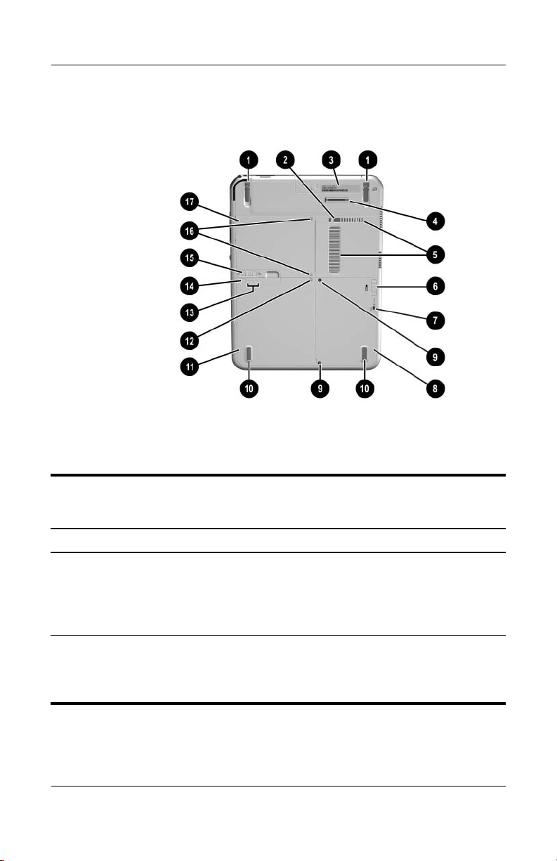
The external components on the rear of the tablet PC are shown in
the following illustration and described in Table 1-52.
Rear Components
Table 1-52
Rear Components
Item Component Function
1 Tilt feet (2) While the tablet PC is being used
in portrait orientation on a flat
surface, can elevate the top of the
tablet PC to provide a comfortable
writing and viewing angle.
2 Docking restraint latch recess Accepts the docking restraint latch
on an optional docking station to
secure the tablet PC to the
Docking Station.
Maintenance and Service Guide 1–61

Product Description
Table 1-52
Rear Components
Item Component Function
3 Product identification label Contains the serial number of the
4 Docking connector Connects the tablet PC to an
5 Air vent Allows airflow to cool internal
6 Attachment release latch Releases an optional screen
(Continued)
tablet PC and a code describing
the original configuration of the
tablet PC. You will need the serial
number if you contact Customer
Care.
optional docking station.
components.
WARNING: To avoid
Å
potential discomfort or burns,
do not block the air vents or
use the tablet PC on your lap
for extended periods. This
tablet PC is designed to run
demanding applications at
full power. As a result of
increased power
consumption, it is normal for
the tablet PC to feel warm or
hot when used continuously.
The tablet PC complies with
the user-accessible surface
temperature limits defined by
the International Standard for
Safety of Information
Technology Equipment
(IEC 60950).
protector or tablet PC keyboard
from the universal attachment slots
on the tablet PC.
7 Hard drive retention screw Secures the hard drive bay cover to
the tablet PC.
1–62 Maintenance and Service Guide

Product Description
Table 1-52
Rear Components
Item Component Function
8 Hard drive bay Holds the system hard drive.
9 Hard drive security screws (2) Secure the hard drive in the hard
10 Pad feet (2) Stabilize the tablet PC when it is
11 Battery bay Holds the battery pack.
12 Battery retention screw Secures the battery pack to the
13 Battery quick check lights (3) On: Each light represents a
(Continued)
drive bay.
placed on a flat surface.
tablet PC.
percentage of a full charge. For
example, when all three lights are
on, the battery pack is fully
charged.
Flashing: When one light is
flashing, less than 10% of a full
charge remains in the battery pack.
14 Battery quick check button Activates the battery quick check
lights, which display how much
of a full charge remains in the
battery pack.
15 Battery pack release latch Releases the battery pack from the
battery bay.
Maintenance and Service Guide 1–63

Product Description
Table 1-52
Rear Components
Item Component Function
(Continued)
16 Memory module and Mini PCI
compartment cover retention
screws
17 Memory module and
Mini PCI compartment
Secure the memory and Mini PCI
compartment cover to the
tablet PC.
Contains one memory slot for a
PC133-compliant memory module.
Also holds an optional Mini PCI
board, such as a modem board or a
combination modem and wireless
board.
To prevent an unresponsive
Ä
system and the display of a
warning message, install only
a Mini PCI device authorized
for use by the governmental
agency that regulates
wireless devices in your
country. If you install a device
and then receive a warning
message, remove the device
to retore tablet PC
functionality. Then contact
Customer Care.
1–64 Maintenance and Service Guide

1.6 Keyboard Components
The keyboard top components are shown in the following
illustration and described in Table 1-53.
Keyboard Top Components
Product Description
Table 1-53
Keyboard Top Components
Item Component Function
1 Alignment key Ensures that the tablet PC is attached to the
keyboard in the correct orientation.
2 Keyboard hooks (2) Secure the tablet PC to the keyboard.
3 Keyboard connector Connects the keyboard to the keyboard
connector on the tablet PC.
4 Tilt adjustment Tilts the tablet PC forward or backward while
it is connected to the keyboard.
Maintenance and Service Guide 1–65

Product Description
Table 1-53
Keyboard Top Components
Item Component Function
5 Rotation disk Rotates the tablet PC clockwise or
counterclockwise while it is connected to the
keyboard.
(Continued)
6 Docking alignment
notches (4)
7 Docking connector
pass-through
8 Pointing stick Moves the cursor and selects and activates
9 Pointing stick buttons (2) Function like the left and right buttons on an
10 Keyboard latch Slide to lock the keyboard or to release the
11 Caps lock light When this light is on, the caps lock is on.
12 Num lock light When this light is on, the numeric keypad is
Help guide the tablet PC and keyboard into
an optional HP Tablet PC Docking Station.
Enables the optional docking station to be
connected to the tablet PC while the
keyboard is attached to the tablet PC.
items on the screen.
external mouse.
keyboard from the tablet PC.
active.
1–66 Maintenance and Service Guide

Product Description
The special keys on the keyboard are shown in the following
illustration and described in Table 1-54.
Keyboard Special Keys
Table 1-54
Keyboard Special Keys
Item Component Function
1 Function keys Perform system and application tasks. For
example, in the Windows operating system
and many applications, pressing F1 opens a
Help file. To enter an F11 function, press
F11/F12. To enter an F12 function, press
Fn+F11/F12.
2 Fn key Combines with other keys to perform system
tasks. For example, pressing Fn+num lk turns
on the keypad.
Maintenance and Service Guide 1–67

Product Description
Table 1-54
Keyboard Special Keys
Item Component Function
3 Windows logo key Displays the Microsoft Windows Start Menu.
(Continued)
4Windows
applications key
5 Keypad keys Used like an external numeric keypad.
Displays a shortcut menu for items beneath
the pointer.
1–68 Maintenance and Service Guide

Product Description
The components on the rear and bottom of the optional
keyboard are shown in the following illustration and described in
Table 1-55.
Keyboard Rear and Bottom Components
Table 1-55
Keyboard Rear and Bottom Components
Item Component Function
1 Screen protector slots Attach the screen protector to the keyboard.
2 Attachment release
switch
3 Universal alignment slots Secure the portfolio or optional screen
4 Alignment key slots Accept alignment keys to ensure proper
Maintenance and Service Guide 1–69
Releases a portfolio or optional screen
protector from the keyboard.
protector to the keyboard.
orientation.

Product Description
1.7 HP Tablet PC Docking Station Components
The upper and right-side components on the optional
HP Tablet PC Docking Station are shown in the following
illustration and described in Table 1-56.
Docking Station Upper and Right-Side Components
Table 1-56
Docking Station Upper and
Right-Side Components
Item Component Function
1 Docking stand Holds the tablet PC when it is docked.
2 Docking eject pin Disconnects the tablet PC and docking stand
docking connectors when the release handle
is pulled.
3 Release handle Ejects the tablet PC from the docking stand.
1–70 Maintenance and Service Guide

Product Description
Table 1-56
Docking Station Upper and
Right-Side Components
Item Component Function
4 Docking connector Connects to the tablet PC.
5 Docking restraint latch Secures the tablet PC to the docking stand.
(Continued)
6 Docking alignment
brackets (2)
7 Security cable slot Attaches an optional security cable to the
8 MultiBay release lever Ejects a MultiBay device from the bay.
9 External MultiBay
connector
Fit into the tablet PC docking alignment
slots to align the tablet PC in the docking
stand.
tablet PC.
The purpose of security solutions is
Ä
to act as a deterrent. These solutions
do not prevent the product from being
mishandled or stolen.
Connects optional USB devices.
Maintenance and Service Guide 1–71

Product Description
The front and left-side components on the optional docking
station are shown in the following illustration and described in
Table 1-57.
Docking Station Front and Left-Side Components
Table 1-57
Docking Station Front and Left-Side Components
Item Component Function
1 Pivot arm Tilts the docking stand forward and
backward to enable different viewing angles
and different docking modes.
2 MultiBay Supports a diskette drive, CD-ROM or
CD-RW drive, DVD-ROM drive,
DVD/CD-RW Combo Drive, or second hard
drive.
3 RJ-45 (network) jack Connects a network cable.
4 External monitor port Connects an optional external monitor or
overhead projector.
1–72 Maintenance and Service Guide

Product Description
Table 1-57
Docking Station Front and Left-Side Components
Item Component Function
5 Audio-in jack Connects the stereo audio function of
optional audio devices such as CD-ROM
players.
(Continued)
6 Audio-out (headphone)
jack
7 USB ports (3) Connect optional USB devices.
8 AC power connector Connects an AC adapter cable, aircraft
Connects optional stereo headphones or
powered stereo speakers and connects the
audio function of an audio/video device such
as a television or VCR.
power adapter, or automobile power
charger/adapter.
Maintenance and Service Guide 1–73

Product Description
1.8 Design Overview
This section presents a design overview of key parts and features
of the tablet PC. Refer to Chapter 3, “Illustrated Parts Catalog‚"
to identify replacement parts, and Chapter 5, “Removal and
Replacement Procedures," for disassembly instructions.
The system board provides the following device connections:
■ Memory module
■ Hard drive
■ Display
■ Optional keyboard and pointing stick
■ Audio
■ Intel Pentium M or Celeron processor
■ Fan
■ PC Card
■ Secure Digital (SD) Memory card (not SD I/O)
■ External MultiBay
■ Modem or modem/NIC
CAUTION: To prevent overheating, do not obstruct vents. Do not allow
Ä
a hard surface, such as a printer, or a soft surface, such as pillows or
thick rugs, to block airflow.
The tablet PC uses an electric fan for ventilation. The fan is
controlled by a temperature sensor and is designed to operate
automatically when high temperature conditions exist. These
conditions are affected by high external temperatures, system
power consumption, power management, battery conservation
configurations, battery fast charging, and software applications.
Cooling air is taken in through the air vent located on the rear of
the tablet PC. Exhaust air is expelled through the air vent located
on the left side of the tablet PC.
1–74 Maintenance and Service Guide

Troubleshooting
WARNING: Only authorized technicians trained by HP should repair
Å
this equipment. All troubleshooting and repair procedures are detailed
to allow only subassembly/module level repair. Because of the
complexity of the individual boards and subassemblies, do not attempt
to make repairs at the component level or to make modifications to any
printed wiring board. Improper repairs can create a safety hazard. Any
indication of component replacement or printed wiring board
modification may void any warranty or exchange allowances.
2
Maintenance and Service Guide 2–1

Troubleshooting
2.1 Setup and Diagnostics Utilities
Selecting Setup or HP Diagnostics
The tablet PC features 2 HP system management utilities:
■ Setup—A system information and customization utility that
can be used even when your operating system is not working
or will not load. This utility includes settings that are not
available in Windows.
■ HP Diagnostics—A system information and diagnostic
utility that is used within your Windows operating system.
Use this utility whenever possible to
❏ Display system information.
❏ Test system components.
❏ Troubleshoot a device configuration problem in
Windows Tablet PC Edition.
It is not necessary to configure a device connected to a USB
✎
port on the tablet PC or to an optional docking station.
Using Setup
Information and settings in Setup are accessed from the File,
Security, or Advanced menus:
1. Turn on or restart the tablet PC. Press
F10 = ROM Based Setup message displays in the lower-left
corner of the screen.
❏ To change the language, press F2.
❏
To view navigation information, press F1.
To return to the Setup menu, press esc.
❏
2. Select the File, Security, or Advanced menu.
2–2 Maintenance and Service Guide
F10 while the

Troubleshooting
3. To close Setup and restart the tablet PC:
❏ Select File > Save Changes, and Exit and press enter.
– or –
❏ Select File > Ignore Changes, and Exit and press enter.
4. When you are prompted to confirm your action, press F10.
Selecting from the File Menu
Table 2 -1
File Menu
Select To Do This
System Information ■ View identification information about the
tablet PC, a docking station, and any battery
packs in the system.
■ View specification information about the
processor, memory and cache size, and
system ROM.
Save to Floppy Save system configuration settings to a diskette.
Restore from Floppy Restore system configuration settings from a
diskette.
Restore Defaults Replace configuration settings in Setup with
factory default settings. Identification information
is retained.
Ignore Changes and Exit Cancel changes entered during the current
session, and then exit and restart the tablet PC.
Save Changes and Exit Save changes entered during the current session,
and then exit and restart the tablet PC.
Maintenance and Service Guide 2–3

Troubleshooting
Selecting from the Security Menu
Table 2 -2
Security Menu
Select To Do This
Setup Password Enter, change, or delete a setup password.
(The setup password is called an administrator
password in HP Computer Security, a program
accessed from the Windows Control Panel.)
Power-on Password Enter, change, or delete a power-on password.
DriveLock Password Enable/disable DriveLock; change a DriveLock
User or Master password.
DriveLock Settings are accessible only
✎
when you enter Setup by turning on
(not restarting) the tablet PC.
Password Options Enable/disable:
■ QuickLock
■ QuickLock on Suspend
■ QuickBlank
To enable QuickLock on Suspend or
✎
QuickBlank, you must first enable
QuickLock.
Password options can be selected only
✎
when a power-on password has been set.
2–4 Maintenance and Service Guide

Table 2 -2
Troubleshooting
Security Menu
Select To Do This
Device Security Enable/disable:
■ Ports or diskette drives*
■ Diskette write*
■ CD-ROM or diskette startup
✎
System IDs Enter identification numbers for the tablet PC,
a docking station, and all battery packs in the
system.
*Not applicable to SuperDisk LS-120 drives.
(Continued)
Settings for a DVD-ROM can be entered in
the CD-ROM field.
Maintenance and Service Guide 2–5

Troubleshooting
Selecting from the Advanced Menu
Table 2 -3
Advanced Menu
Select To Do This
Language (or press F2) Change the Setup language.
Boot Options Enable/disable:
■ QuickBoot, which starts the tablet PC more
quickly by eliminating some startup tests. If you
suspect a memory failure and want to test
memory automatically during startup, disable
QuickBoot.
■ MultiBoot, which sets a startup sequence that
can include most bootable devices and media
in the system.
Device Options ■ Enable/disable the embedded numeric keypad
at startup.
■ Enable/disable multiple standard pointing
devices at startup. To set the tablet PC to
support only a single, usually nonstandard,
pointing device at startup, select Disable.
■ Enable/disable USB legacy support for a USB
keyboard. When USB legacy support is
enabled, the keyboard works even when a
Windows operating system is not loaded.
■ Set an optional external monitor or overhead
projector connected to a video card in a
docking station as the primary device. When
the tablet PC display is set as secondary, the
tablet PC must be shut down before undocking
from a docking station.
2–6 Maintenance and Service Guide

Table 2 -3
Troubleshooting
Advanced Menu
Select To Do This
Device Options
HDD Self-Test Options Run a quick comprehensive self-test on hard
*Video modes can vary within regions. However, NTSC is commonly used in
North America; PAL, in Europe, Africa, and the Middle East; NTSC-J, in Japan;
and PAL-M, in Brazil. Other South and Central American regions may use
NT S C, PA L , o r PA L -M.
(continued)
■ Change the parallel port mode from
EPP (Enhanced Parallel Port [default]) to
standard, bidirectional, EPP or ECP
(Enhanced Capabilities Port).
■ Set video-out mode to NTSC (default), PAL,
NTSC-J, or PAL-M.*
■ Enable/disable all settings in the SpeedStep
window. When Disable is selected, the
tablet PC runs in Battery Optimized mode.
■ Specify how the tablet PC recognizes multiple
identical docking stations that are identically
equipped. Select Disable to recognize the
docking stations as a single docking station;
select Enable to recognize the docking stations
individually, by serial number.
■ Enable/disable the reporting of the processor
serial number by the processor to the software.
drives in the system that support the test features.
(Continued)
Maintenance and Service Guide 2–7

Troubleshooting
2.2 Using HP Diagnostics for Windows
When you access HP Diagnostics for Windows, a scan of all
system components is displayed on the screen before the
HP Diagnostics window opens.
You can display more or less information from anywhere within
HP Diagnostics for Windows by selecting Level on the menu bar.
HP Diagnostics for Windows is designed to test HP components.
If third-party components are tested, the results may be
inconclusive.
Obtaining, Saving, or Printing Configuration Information
1. Access HP Diagnostics by selecting Start > Control Panel >
Diagnostics for Windows.
2. Select Categories, and then select a category from the
drop-down list.
❏ To save the information, select File > Save As.
❏ To print the information, select File > Print.
3. To close HP Diagnostics for Windows, select File > Exit.
2–8 Maintenance and Service Guide

Troubleshooting
Obtaining, Saving or Printing Diagnostic Test Information
1. Access HP Diagnostics by selecting Start > Control Panel >
Diagnostics for Windows.
2. Select the Test tab.
3. In the scroll box, select the category or device you want
to test.
4. Select a test type:
❏ Quick Test—Runs a quick, general test on each device in
a selected category.
❏ Complete Test—Performs maximum testing on each
device in a selected category.
❏ Custom Test—Performs maximum testing on a selected
device.
◆ To run all tests for your selected device, select
Check All.
◆ To run only the tests you select, select Uncheck All,
and then select the check box for each test you want
to run.
5. Select a test mode:
❏ Interactive Mode—Provides maximum control over the
testing process. You determine whether the test was
passed or failed. You may be prompted to insert or
remove devices.
❏ Unattended Mode—Does not display prompts. If errors
are found, they are displayed when testing is complete.
Maintenance and Service Guide 2–9

Troubleshooting
6. Select Begin Testing.
7. Select a tab to view a test report:
❏ Status tab—Summarizes the tests run, passed, and failed
❏ Log tab—Lists tests run on the system, the number of
❏ Error tab—Lists all errors found in the tablet PC, along
8. Select a tab to save the report:
❏ Log tab—Select Log tab Save.
❏ Error tab—Select Error tab Save.
9. Select a tab to print the report:
Log tab—Select File > Save As, and then print the file from
your folder.
during the current testing session.
times each test has run, the number of errors found on
each test, and the total run time of each test.
with their error codes.
2–10 Maintenance and Service Guide

Troubleshooting
Troubleshooting Flowcharts
Tabl e 2-4
Troubleshooting Flowcharts Overview
Flowchart Description
2.1 “Flowchart 2.1—Initial Troubleshooting.”
2.2 “Flowchart 2.2—No Power, Part 1.”
2.3 “Flowchart 2.3—No Power, Part 2.”
2.4 “Flowchart 2.4—No Power, Part 3.”
2.5 “Flowchart 2.5—No Power, Part 4.”
2.6 “Flowchart 2.6—No Video, Part 1.”
2.7 “Flowchart 2.7—No Video, Part 2.”
2.8 “Flowchart 2.8—Nonfunctioning Docking Station (if applicable).”
2.9 “Flowchart 2.9—No Operating System (OS) Loading.”
2.10 “Flowchart 2.10—No OS Loading from Hard Drive, Part 1.”
2.11 “Flowchart 2.11—No OS Loading from Hard Drive, Part 2.”
2.12 “Flowchart 2.12—No OS Loading from Hard Drive, Part 3.”
2.13 “Flowchart 2.13—No OS Loading from Diskette Drive.”
2.14 “Flowchart 2.14—No OS Loading from CD-ROM or DVD-ROM
Drive.”
2.15 “Flowchart 2.15—No Audio, Part 1.”
2.16 “Flowchart 2.16—No Audio, Part 2.”
2.17 “Flowchart 2.17—Nonfunctioning Device.”
2.18 “Flowchart 2.18—Nonfunctioning Keyboard.”
2.19 “Flowchart 2.19—Nonfunctioning Pointing Device.”
2.20 “Flowchart 2.20—No Network or Modem Connection.”
Maintenance and Service Guide 2–11

Troubleshooting
Flowchart 2.1—Initial Troubleshooting
Begin
troubleshooting.
N
Go to
Flowchart 2.2—No
Power, Part 1.
Check
LED board,
speaker
connections.
Go to
Flowchart 2.6—No
Video, Part 1.
Go to
Flowchart 2.9—No
Operating System
(OS) Loading.
Go to
Flowchart 2.15—No
Audio, Part 1.
Y
Y
Y
All drives
working?
Keyboard/
pointing
device
working?
Connecting
to network
or modem?
End
N
2.17—Nonfunctioning
N
2.18—Nonfunctioning
or Flowchart
2.19—Nonfunctioning
Pointing Device.
N
Flowchart 2.20—No
Modem Connection.
Y
LEDs, or error
Y
Is there video?
Y
Y
Y
Is there
power?
Beeps,
messages?
(no boot)
Is the OS
loading?
Is there
sound?
N
N
N
N
Go to
Flowchart
Device.
Go to
Flowchart
Keyboard
Go to
Network or
2–12 Maintenance and Service Guide

Flowchart 2.2—No Power, Part 1
No Power
(power LED
is off).
Remove from
docking station
(if applicable).
Troubleshooting
N
Power up
on battery
power?
*Reset
power.
Y
N
Power up
on AC
power?
*Reset
power.
Y
Y
Power up
in docking
station?
Done
N
1. Reseat the power cable in the docking
station and at the AC outlet.
2. Ensure the AC power source is active.
YN
Done
Power up
in docking
station?
N
Power up
on battery
power?
Go to
Flowchart 2.3—No
Power, Part 2.
Y
N
Power up
on AC
power?
Go to
Flowchart 2.4—No
Power, Part 3.
Y
*NOTES:
To reset the tablet PC, slide and hold the
power switch for 4 seconds.
Go to
Flowchart
2.8—Nonfunctioning
Docking Station (if
applicable).
Maintenance and Service Guide 2–13

Troubleshooting
N
Flowchart 2.3—No Power, Part 2
Continued from
Flowchart 2.2—No
Power, Part 1
Visually check for
debris in battery
socket and clean
if necessary.
Y
Power on?
Check battery by
recharging,
moving it to
another tablet PC,
or replacing it.
Done
N
Replace
Power on?
power supply
(if applicable).
Y
N
Done
Power on?
Go to
Flowchart 2.4—No
Power, Part 3
Y
Done
2–14 Maintenance and Service Guide

Flowchart 2.4—No Power, Part 3
Continued from
Flowchart 2.3—No
Power, Part 2.
Plug directly
into AC outlet.
Y
Troubleshooting
Power LED
on?
N
Reseat AC adapter
in tablet PC and
at power source.
Power on?
N
Power outlet
active?
Y
Replace
power cord.
Power on?
Done
Y
Done
N
Try different
outlet.
Internal or
external AC
Internal
Flowchart 2.5—No
Power, Part 4.
Y
Done Done
adapter?
Go to
External
Replace external
AC adapter.
N
Power on?
Y
N
Maintenance and Service Guide 2–15

Troubleshooting
Flowchart 2.5—No Power, Part 4
Continued from
Flowchart 2.4—No
Power, Part 3.
Open
tablet PC.
N
Y
Loose or
damaged
parts?
Close
tablet PC and
retest.
Power on?
Done
Y
Reseat loose
components and
boards and
replace damaged
items.
N
Replace the following items (if applicable).
Check tablet PC operation after each
replacement:
1. Internal AC-DC converter*
2. Internal AC adapter
3. Processor board*
4. System board*
*NOTE: Replace these items as a set to prevent
shorting out among components.
2–16 Maintenance and Service Guide

Flowchart 2.6—No Video, Part 1
No Video.
Docking
Station
Stand-alone
or in docking
station?
Go to
Flowchart 2.7—No
Video, Part 2.
*NOTE: To change from internal to
external display, use the hotkey
combination.
Troubleshooting
Stand-alone
Y
Internal or
External
brightness.
external
display*?
Adjust
Internal
Adjust
brightness.
A
Video OK? Done
N
Y
Video OK? Done
N
Replace the following one at a time. Test after each replacement.
Check for bent
pins on cable.
Video OK?
1. Cable between notebook and tablet PC display (if applicable)
2. Inverter board (if applicable)
3. Display
4. System board
N
Try
another
display.
Internal and
external
video OK?
N
Replace
system
board.
YY
Done
Done
Maintenance and Service Guide 2–17

Troubleshooting
Flowchart 2.7—No Video, Part 2
Continued from
Flowchart 2.6—No
Video, Part 1.
Remove
tablet PC from
docking station,
if connected.
Adjust
display
brightness.
N
Video OK?
Flowchart 2.6—No
Video, Part 1.
Y
Check that tablet PC is properly seated
in docking station, for bent pins on
cable, and for
monitor connection.
Y
Video OK?
N
Adjust external
monitor display.
Go to
Done
Check brightness
of external
monitor.
Video OK?
N
Try another
external
monitor.
Internal
and external
video OK?
N
Go to
Flowchart
2.8—Nonfunctioning
Docking Station (if
applicable).
Y
Done
Y
Done
2–18 Maintenance and Service Guide

Flowchart 2.8—Nonfunctioning
Docking Station (if applicable)
Nonfunctioning
docking station.
Reseat power
cord in docking
station and
power outlet.
Troubleshooting
Check voltage
setting on
docking station.
Reset monitor
cable connector at
docking station.
Docking
station
operating?
N
Remove
tablet PC, reset
all internal parts,
and replace any
damaged items in
docking station.
Reinstall
tablet PC into
docking station.
Y
Docking
station
operating?
Done
N
Y
Done
Replace the following docking station
components one at a time. Check tablet PC
operation after each replacement.
1. Power supply
2. I/O board
3. Backplane board
4. Switch box
5. Docking motor mechanism
Maintenance and Service Guide 2–19

Troubleshooting
Flowchart 2.9—No Operating System (OS)
Loading
No OS
loading.*
Reseat power
cord in docking
station and
power outlet.
No OS loading
from hard drive,
go to
Flowchart 2.10—No
OS Loading from
Hard Drive, Part 1.
No OS loading
from diskette
drive, go to
Flowchart 2.13—No
OS Loading from
Diskette Drive.
No OS loading
from CD-ROM or
DVD-ROM drive,
go to Flowchart
2.14—No OS
Loading from
CD-ROM or
DVD-ROM Drive.
No OS loading
from network,
go to
Flowchart 2.20—No
Network or
Modem Connection.
*NOTE: Before beginning troubleshooting, always
check cable connections, cable ends, and drives
for bent or damaged pins.
2–20 Maintenance and Service Guide
 Loading...