

Page 1

June 1998
....................
..................
......................
.....................
......................
................
....................
..............................
.........................
.........................
............................
...........
.............
................
..........................
.........................
..................
.......................
................
...............
......
...............
....................
Compaq Computer
Corporation
ECG Technology
Communications
ONTENTS
C
Introducti on
High-Performance
Technologies
Pentium II Xeon Proces sor
Technology
Pentium II Xeon
Performance
ProLiant 7000
Architecture
High-Availability
Technologies
Redundant Network
Interface Cont roller
Technology
Redundant, Hot-Plug
Fans
Redundant Processor Pow er
Modules
Redundant Hot-Plug Power
Supplies
Hot-Plug Hard Disk
Drives
Compaq Smart Array
3100ES Controller
PCI Hot Plug Tec hnology
for PCI Adapters
Management
Technologies
Integrated Management
Display
Integrated Remot e
Console
Auto-Default ROM
Configuration
Serviceability
Features
ProLiant 7000
Upgrade P ath
Power Supplies
Fan Cooling Capacity
Chassis Design
Conclusion
1
ECG078/0698
3
3
3
5
6
10
11
11
13
13
16
16
17
18
19
19
19
20
20
21
21
22
23
T
ECHNOLOGY
.
.
.
.
.
Compaq ProLiant 7000 Server Technology
.
.
.
.
.
.
This technology brief describes the high-performance, high-availability, and management
.
.
.
technologies built into the Compaq ProLiant 7000 Server. The high-performance
.
.
.
technologies include Intel’s 32-bit Pentium® II Xeon™ processor, as well as
.
.
.
improvements to the ProLiant 7000’s PCI bus architecture. Compaq has fulfilled its
.
.
.
promise to extend the functionality of the ProLiant 7000 by providing an upgrade path to
.
.
.
four or eight Pentium II Xeon processors.
.
.
.
.
.
The high-availability technologies include: PCI Hot Plug technology, redundant network
.
.
.
interface controllers, redundant hot-plug power supplies, drives, and fans; and
.
.
.
redundant processor power modules. The ProLiant 7000 design also contains easy-
.
.
.
.
access components that reduce downtime for service or upgrades. The ProLiant 7000
.
.
.
incorporates key management technol ogi es, s uch as t he Int egrat ed Management Di s pl ay,
.
.
.
Integrated Remote Console, and Auto-Default ROM Configuration, that further enhance
.
.
.
availability.
.
.
.
.
.
The intended audience for this paper is the engineer or system administrator familiar
.
.
.
with existing Compaq technology and servers. For those less familiar with Compaq
.
.
.
technology, please see the related technology briefs referenced in this document. For
.
.
.
more information about the ProLiant 7000, see the complete list of features at
.
.
.
http://www.compaq.com/products/servers/ProLiant7000/quickspecs.html.
.
.
.
.
.
.
.
.
.
.
.
.
.
.
.
.
.
.
.
.
.
.
.
.
.
.
.
.
.
.
.
.
.
.
.
.
.
.
.
.
.
.
.
.
.
.
.
.
.
.
.
.
.
.
.
.
.
.
.
.
.
.
.
.
.
.
.
.
.
.
.
.
.
.
.
.
.
.
.
.
.
Please direct comments regarding this communication to the ECG Technology Communications Group at this Internet address:
.
.
TechCom@compaq.com
.
.
.
.
.
.
.
B
RIEF
Page 2

ECG078/0698
ECHNOLOGY BRIEF
T
.
.
.
OTICE
N
.
.
.
.
.
The information in this publication is subject to change without notice and is provided “AS IS”
.
.
.
WITHOUT WARRANTY OF ANY KIND. THE ENTIRE RISK ARISING OUT OF THE USE
.
.
.
OF THIS INFORMATION REMAINS WITH RECIPIENT. IN NO EVENT SHALL COMPAQ
.
.
.
BE LIABLE FOR ANY DIRECT, CONSEQUENTI AL, INC I DE NT AL, SPECIAL, PUNITIVE
.
.
.
OR OTHER DAMAGES WHATSOEVER (INCLUDING WITHOUT LIMITATION,
.
.
DAMAGES FOR LOSS OF BUSINESS PROFITS, BUSINESS INTERRUPTION OR LOSS OF
.
.
.
BUSINESS INFORMATION), EVEN I F COMPAQ HAS BEEN ADVI SE D OF T HE
.
.
.
POSSIBILITY OF SUCH DAMAGES.
.
.
.
.
.
The limited warranties for Compaq products are exclusively set forth in the documentation
.
.
.
accompanying such products. Nothing herein should be construed as constituting a further or
.
.
.
additional warranty.
.
.
.
.
This publication does not constitute an endorsement of the product or products that were tested.
.
.
.
The configuration or configurations tested or described may or may not be the only available
.
.
.
solution. This test is not a determination of product quality or correctness, nor does it ensure
.
.
.
compliance with any federal state or local requirements.
.
.
.
.
Compaq, Compaq Insight Manager, ProLiant, ROMPaq, and SmartStart are trademarks and/or
.
.
.
service marks of Compaq Computer Corporation.
.
.
.
.
.
Netelligent and MultiLock are trademarks and/or service marks of Compaq Computer
.
.
.
Corporation.
.
.
.
.
Micr osoft and Windows are trademar k s and/or regist ered trad emar k s of Mi crosoft Cor p orat ion.
.
.
.
.
Pentium, Pentium Pro, and Pentium II Xeon are registered trademarks of Intel Corporation.
.
.
.
.
.
Other product names mentioned herein may be trademarks and/or registered trademarks of their
.
.
.
respective companies.
.
.
.
.
©1998 Compaq Computer Corporation. All ri ghts reserved. Printed in t he U.S.A.
.
.
.
.
.
.
.
.
.
.
.
.
.
.
.
.
Compaq ProLiant 7000 Server Technology
.
.
.
Second Edition (June 1998)
.
.
ECG078/0698
.
.
.
.
.
.
.
.
.
.
.
.
.
.
.
.
.
.
.
.
.
.
.
.
.
.
.
.
.
.
.
.
.
.
.
.
.
.
.
.
.
.
.
.
.
.
.
.
.
2
(cont.)
Page 3
ProLiant 7000 Server
ECG078/0698
ECHNOLOGY BRIEF
T
.
.
NTRODUCTION
I
.
.
.
.
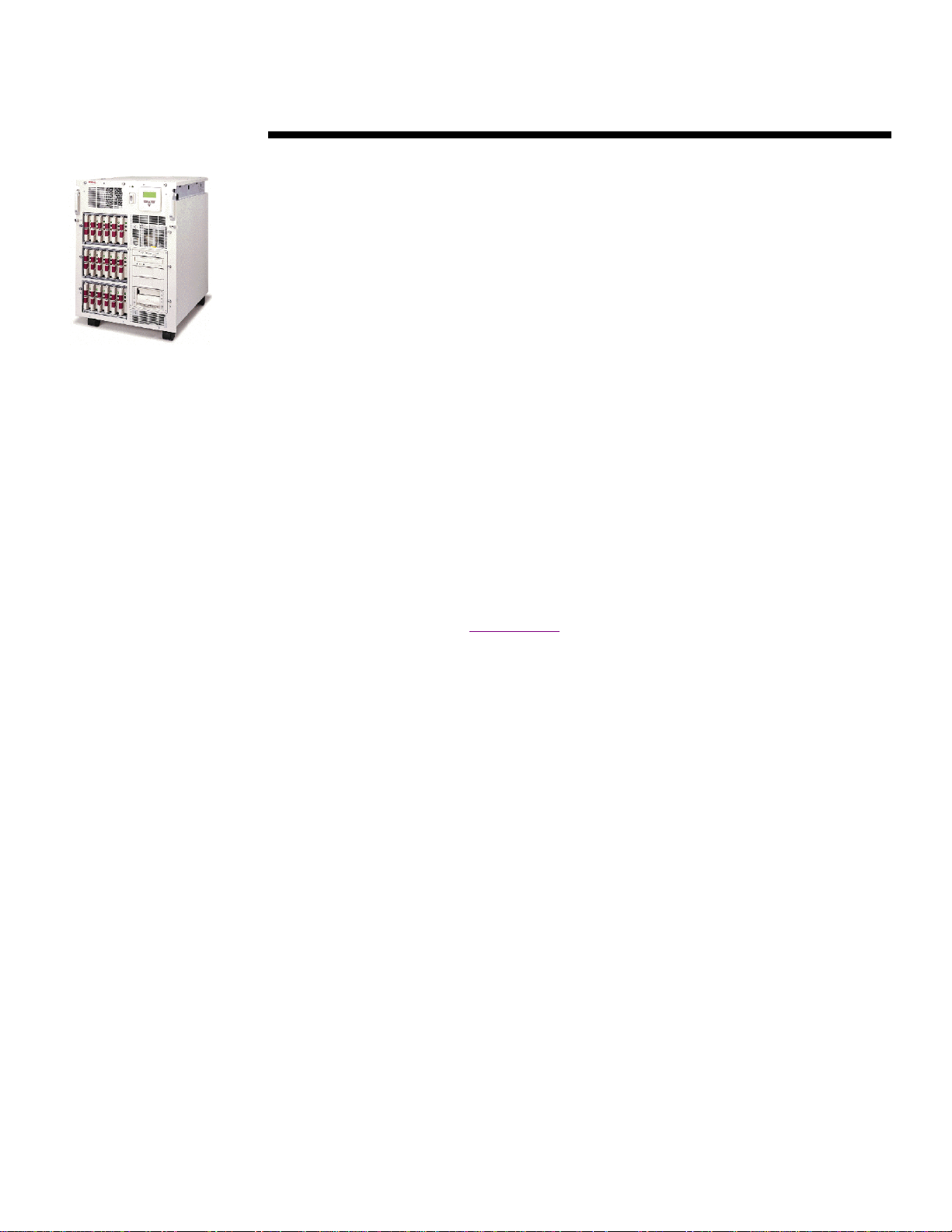
In today’s business environment, customers require powerful servers with fault-tolerant features
.
.
.
to keep their businesses running 24 h ours a da y, 7 days a week. The Compaq ProLiant 7000
.
.
.
Server provides breakthrough high-performance and high-availability technologies that keep the
.
.
.
server up and running in t he most demanding 7x24 environmen ts. This technology brief explains
.
.
.
the features of the new ProLiant 7000 Servers that support Penti um II Xeon processors, and how
.
.
.
previously purchased ProLiant 7000 Servers can be upgraded to support up to four Pentium II
.
.
.
Xeon processors. This upgra de path provides investment protection and gives customers
.
.
.
confidence of a long life for the ProLiant 7000.
.
.
.
.
This technology brief also describes the management technologies of the ProLiant 7000 Server.
.
.
.
Many of these technologies are covered in more detail in separate technology briefs, which are
.
.
.
referenced in this document.
.
.
.
.
.
.
.
.
IGH-PERFORMANCE TECHNOLOGIES
H
.
.
.
.
.
.
Pentium II X eo n Processor Techn o logy
.
.
.
.
The P enti u m II Xeon processor uses t he same core architectu re as p revious Penti um II p rocessors ,
.
.
.
and it continues the same 32-bit technology line, which makes it fully software compatible with
.
.
.
all current Pentium Pro and Pentium II processors. Like the Pentium Pro and Pentium II
.
.
.
processors, the Pentium II Xeon uses dynamic execution techniques and a dual independent bus
.
.
.
structure. Th e dual independent bus structure provides a separate bus between the processor and
.
.
.
the s econdary level 2 (L2 ) cache. S ee the t echnol og y brief
.
.
.
Technology
.
.
.
Pentium II Xeon processor.
.
.
.
.
The Pentium II Xeon processor provides higher levels of performance through architectural
.
.
.
enhan cem ents incl u din g :
.
.
.
.
.
•
.
.
.
.
•
.
.
.
.
.
•
.
.
.
.
•
.
.
.
.
•
.
.
.
.
.
•
.
.
.
.
•
.
.
.
.
.
.
100-MHz AGTL+ System Bus
.
.
.
.
An important enhancement is the move from the 66-MHz GTL+ bus used by the Pentium Pro and
.
.
.
Pentium II processors to the higher frequency 100-MHz AGTL+ bus. This provides faster data
.
.
.
pathways between t he processor and ran d om access memory (RAM), an d bet ween th e p rocessor
.
.
.
and system peripherals.
.
.
.
.
.
.
400- and 450-MHz Core Processor Frequencies
.
.
.
.
One of the most significant differences between the Pentium II Xeon processor and current
.
.
.
Pentium Pro processors is the much higher processor frequency. Pentium II Xeon processors,
.
.
.
currently at 400 MHz, are expected to reach 450 MHz by the end of 1998, and to incr ease beyond
.
.
.
450 MHz in later versions.
.
.
.
.
.
3
, document number ECG050/0698 for more details on the IA32 architecture and the
100-MHz AGTL+ system bus
Processor frequencies starting at 400 MHz and i ncreasing to 450 MHz and beyond
Full - s p eed L2 cach e bus
L2 cache configurations starting at 512 KB an d 1MB and increasing to 2 MB
Slot 2 cartridge
Support for up to 64 GB of cacheable system memory
MMX technology
(cont.)
Deschutes Family Processor
Page 4
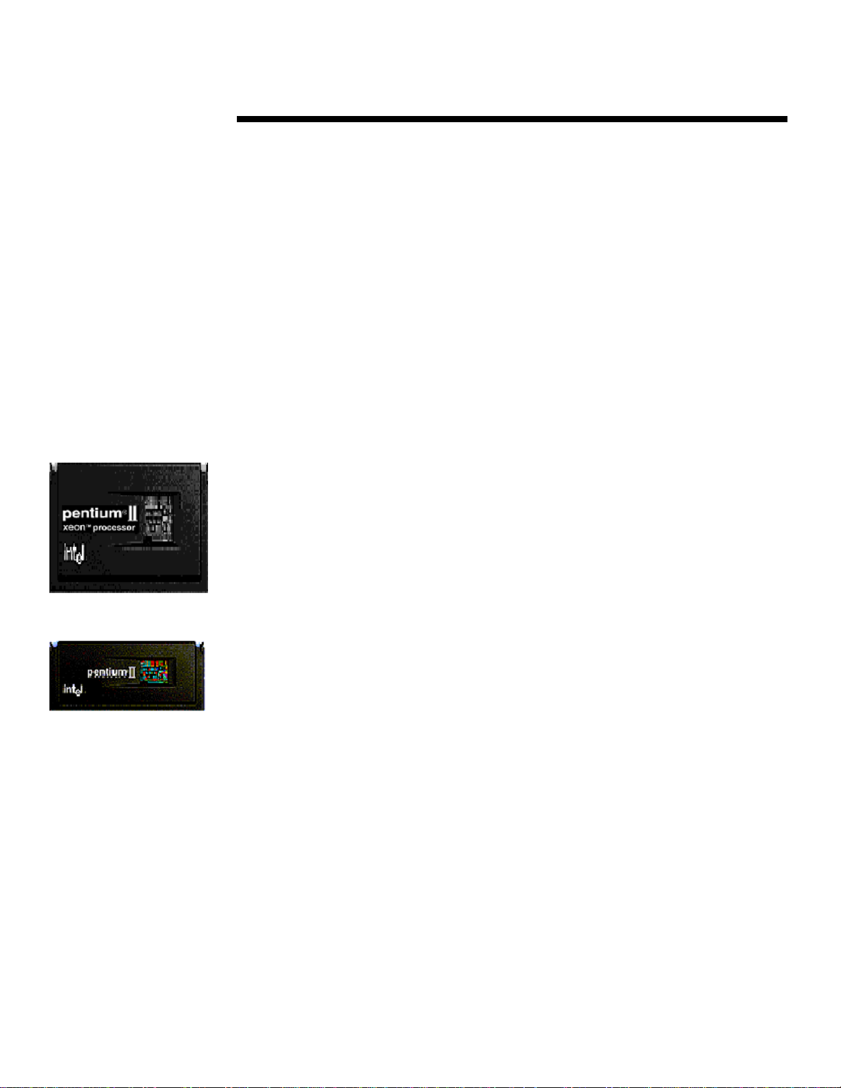
Pentium II Xeon (Slot 2
cartridge)
Pentium II (Slot 1 cartridge.
ECG078/0698
ECHNOLOGY BRIEF
T
.
.
Larger Cache Sizes
.
.
.
.
.
The Pentium II Xeon processor supports larger L2 caches than previous Intel processors.
.
.
.
Pentium II Xeon processors are initially available in 512-KB and 1-MB configurations with future
.
.
plans for a 2-MB cache. I n cont rast, the Pen tium P ro pr ocess or ha s a max imum 1 - M B ca che.
.
.
.
The la rge r data c ach e provides a si gnificant performance boost, es pecially in s ym metric
.
.
.
multiprocessing (SMP) configurations and systems used in memory-intensive applications, such
.
.
.
as on-line transaction processing.
.
.
.
.
.
.
Full-Speed L2 Cache Bus
.
.
.
.
.
Previou s P enti u m II processors have a hal f-s p eed L2 cache bus that connect s the ca che mem ory
.
.
and the centr a l processing unit (CPU) core. Thi s mean s a 266-MHz Pentium II actual ly transfers
.
.
.
data between the L2 cache and CPU core at 133 MHz. In contrast, the Pentium II Xeon processor
.
.
.
has a full-speed cache bus, which means that a 400-MHz Pentium II Xeon processor transfers
.
.
.
data between the L2 cache and pr ocessor core at a full 400 MHz. The combination of the full-
.
.
.
speed cache bus and t he la rger cache size greatly enha nces the performa nce of th e P enti u m II
.
.
.
Xeon processor relative to the Pentium Pro and previous Pentium II processors, especially in
.
.
.
larger SMP configurations and memory-intensive applications.
.
.
.
.
.
.
Slot 2 Cartridge
.
.
.
.
Pent ium II processors ar e packa g ed in a s ingle edge con tact ( S EC) cartridge. The SEC ca rtridg e
.
.
.
for a Pentium II processor inserts into the Slot 1 connector on the motherboard, while the Pentium
.
.
.
II Xeon ’ s SEC cartridge inserts i nto the Slot 2 connector. The for m factor of the Slot 2 cartridg e
.
.
.
is larger than that of the Slot 1. Compared with the Slot 1 cartridge, the Slot 2 cartridge has
.
.
.
.
.
.
.
.
.
.
.
.
.
.
.
.
.
.
.
.
.
.
The lar g er cartridge and corres p onding mot herboa rd con nector for th e P enti u m II Xeon process or
.
.
.
require more pins. The additional pins on the Slot 2 cartridge provide support for a four-
.
.
.
processor (4P) multiprocessing system bus. Load and signal integrity modifications in the new
.
.
.
design allow a Pentium II Xeon processor to drive up to four main loads on the AGTL+ bus—
.
.
.
three other processors and a memory and I/O controller. This allows the Pentium II Xeon to scale
.
.
.
to 4P configurations. The extra pins also provide the additional power and ground connections
.
.
.
needed to support th e larger, full-speed L2 cache.
.
.
.
.
.
.
64-GB Cacheable Address Space
.
.
.
.
The Pentium II Xeon processor is able to access up to 64 GB of RAM; however, the memory
.
.
.
controller chipset determines the actual size of supported memory. Initial Pentium II Xeon
.
.
.
chipsets support memory configurations up to 8 GB.
.
.
.
.
.
.
MMX Technol ogy
.
.
.
.
The Pentium II Xeon processor supports MMX instructions, which allow certain applications to
.
.
.
operate on multiple data locations with a single instruction call to the processor. The MMX
.
.
.
functions are primarily used in multimedia applications such as audio and video manipulation;
.
.
.
however, increasing numbers of specialized business applications are being written to take
.
.
.
advantage of MMX capabilities.
.
.
.
.
.
.
.
.
4
More pins (330 pins versus 242 pins for the Slot 1).
•
Support for a four-processor multiprocessing bus.
•
Load and signal integrity modifications.
•
The ability to deliver more power to support the larger, full-speed L2 cache.
•
(cont.)
Page 5
ECG078/0698
ECHNOLOGY BRIEF
T
.
.
.
Pentium II Xeon Performance
.
.
.
.
Compaq tested performan ce of Pentium II Xeon processors in the ProLiant 7000 server usin g two
.
.
.
industry-standar d benchma rks: the TPC-C benchmark test and the TPC-D version 1.3.1
.
.
.
benchmark test. The TPC-C benchmark measures performance in an on-line transaction
.
.
.
processing environment, while the T P C - D benchm ark repr es ents a broad range of decisi on
.
.
.
support (DS) applications that r equire complex, long-runnin g quer i es against large complex data
.
.
.
structures. Real-world business questions were written against this model, resulting in 17
.
.
.
complex queries.
.
.
.
.
Tables 1 and 2 show the configurations used for these benchmark tests and t he performance
.
.
.
results, which set new industry-wide performance levels for a single-node Intel-based system. For
.
.
.
a full discussion of these benchmark results in comparison to published benchmark results for
.
.
.
other 4-way and 8-way systems, read the Compaq Benchmark Summaries available at
.
.
.
http://www.compaq.com/products/servers/proliant7000-xeon/.
.
.
.
.
.
.
.
.
.
.
.
.
.
.
.
.
.
.
.
.
.
.
.
.
.
.
.
.
.
.
.
.
.
.
.
.
.
.
.
.
.
.
.
.
.
.
.
.
.
.
.
.
.
.
.
.
.
.
.
.
.
.
.
.
.
.
.
.
.
.
.
.
.
.
.
.
.
.
.
.
.
.
.
.
.
.
.
.
.
.
.
.
.
.
.
.
.
.
.
.
.
.
.
.
.
.
.
.
.
.
.
.
.
.
.
.
5
(cont.)
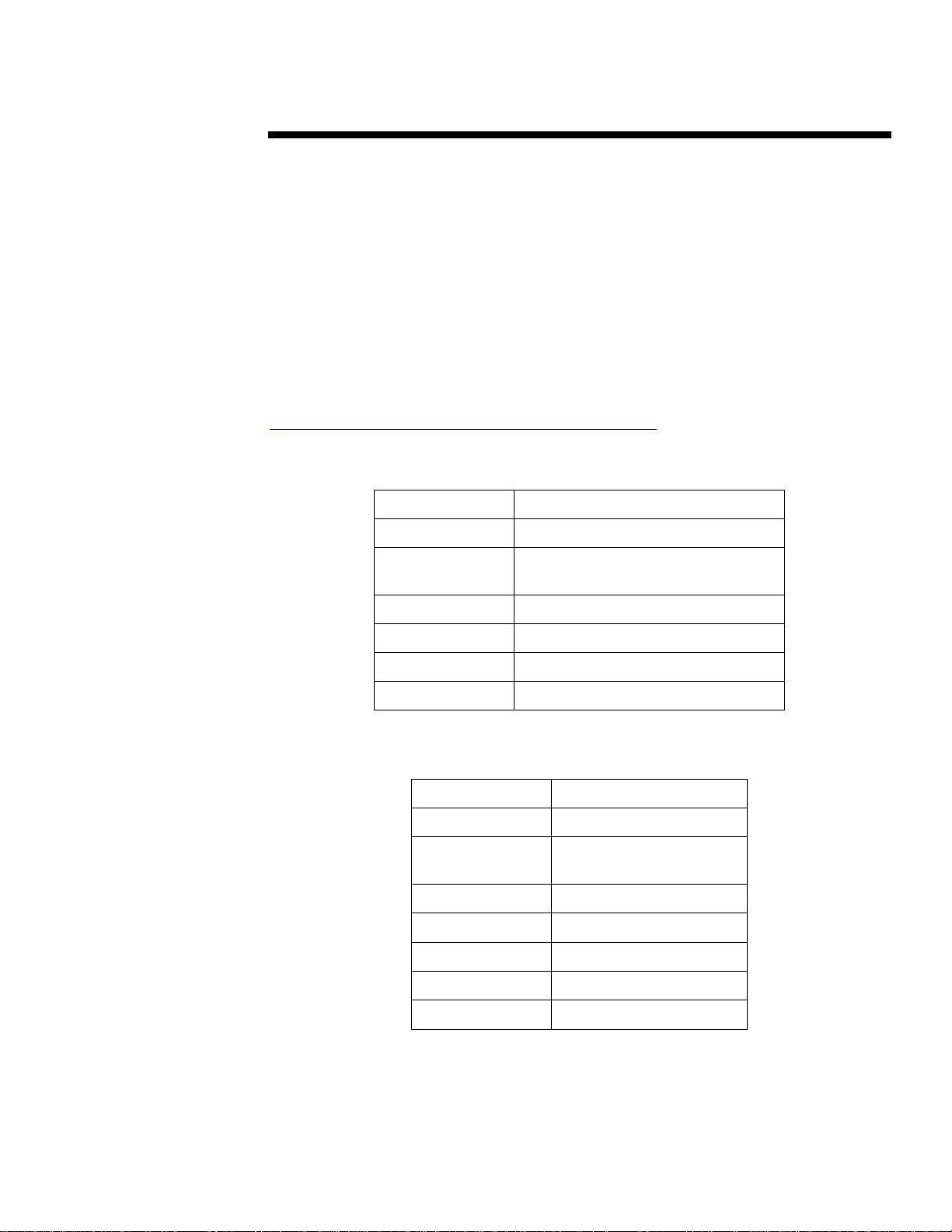
Table 1: Results of TPC-C Benchmark Test
System
No. of Processors
Processor Type
Speed/L2 Cache
TPC-C Throughput
Price:Performance
OS
Database
Compaq ProLiant 7000 Server
4
Pentium II Xeon
400 MHz/1 MB
18,127 tpmC
$27 per tpmC
Windows NT Server 4.0 Enterprise Edit i on
Microsoft SQL Server 7.0 Enterprise Edit i on
Table 2: Results of TPC-D Benchmark Test
System
No. of Processors
Processor Type
Speed/L2 Cache
TPC-D Power
TPC-D Throughput
Price:Performance
OS
Database
Compaq ProLiant 7000 Server
4
Pentium II Xeon
400 MHz/1 MB
1694.6 QPPD @100 GB
553.1 QthD @100 GB
$390.65 per QphD @ 100 GB
Windows NT 4.0
Oracle 8.0.4
Page 6
ECG078/0698
ECHNOLOGY BRIEF
T
.
.
Thermal Design
.
.
.
.
.
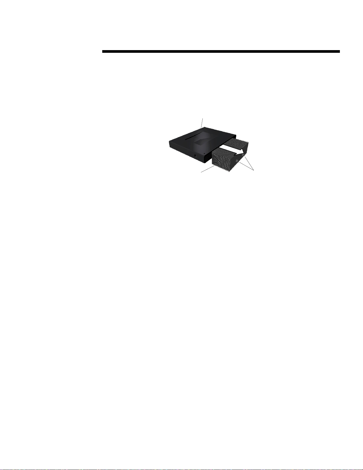
Compaq has designed an innovative thermal cooling solution for the Pentium II Xeon processor
.
.
.
that contributes to increased system reliability and future performance scalability to 8-way
.
.
archit ectures . Heat pipes transfer heat away from the Slot 2 cart rid g e thermal pla te to cooling
.
.
.
fins mounted atop the cartridge (Figur e 1).
.
.
.
.
.
.
.
.
.
.
.
.
.
.
.
.
.
.
.
.
.
.
.
.
.
.
.
.
.
.
.
.
.
.
.
.
.
.
.
.
.
.
.
.
.
This top-mounted position and the direction of the cooling fins are advantageous in two important
.
.
.
ways. First, this design cools efficiently regardless of the direction of air flow (vertical or
.
.
.
horizontal). Therefore, the same Slot 2 cartridge and heat sink combination used in the ProLiant
.
.
.
7000 4-way configuration can also be used in future 8-way configurations by simply reorienting
.
.
the p rocessor s. Second , because t he heat fins are top mou nted, th e redundant p rocessor p ower
.
.
.
module can be placed in its optimal position, next to the processor, to maintain short signal trace
.
.
.
lengths across the 100-MHz system bus (Figure 2). The resulting improvements to power supply
.
.
.
regulation and system bus signal quality increase system reliability. Moreover, the smaller
.
.
.
spacing between processor sockets makes possible future upgrades to 8-way Pentium II Xeon
.
.
.
archit ectures u s ing the same ch assis d esign.
.
.
.
.
.
.
.
.
.
.
.
.
.
.
.
.
.
.
.
.
.
.
.
.
.
.
.
.
.
.
.
.
.
.
.
.
.
.
.
.
.
.
.
.
.
.
.
.
.
.
.
.
.
.
.
.
.
.
.
.
.
.
.
.
.
.
.
.
.
.
.
6
Figure 1: Heat pipes and fins for the Pentium II Xeon processor cartridge.
(cont.)
Pentium II Xeon
Processor Cartridge
Heat
Fins
Heat Pipes
Page 7
ECG078/0698
ECHNOLOGY BRIEF
T
.
.
.
.
.
.
.
.
.
.
.
.
.
.
.
.
.
.
.
.
.
.
.
.
.
.
.
.
.
.
.
.
.
.
.
.
.
.
.
.
.
.
.
.
.
.
.
.
.
.
.
.
.
.
.
.
.
.
.
.
.
.
.
.
.
.
.
.
.
.
.
.
.
.
.
.
.
.
.
.
.
.
.
.
.
.
.
.
.
.
.
.
.
.
.
.
.
.
.
.
.
.
.
.
.
.
.
.
.
.
.
.
.
.
.
.
.
.
.
.
.
.
.
.
.
.
.
.
.
.
.
.
.
.
.
.
.
.
.
.
.
.
.
.
.
.
.
.
.
.
.
.
.
.
.
.
.
7
Memory Expansion
Board Slots
Processor
Sockets
ProLiant 7000 Architecture
The ProLiant 7000 ar ch it ecture all ows customers to scale the processor and memory subsystems
to run their mission-critical applications. The following sections describe the ProLiant 7000
architecture—the processor board, memory expansion boards, input/output (I/O) board, and
standard per i pheral board.
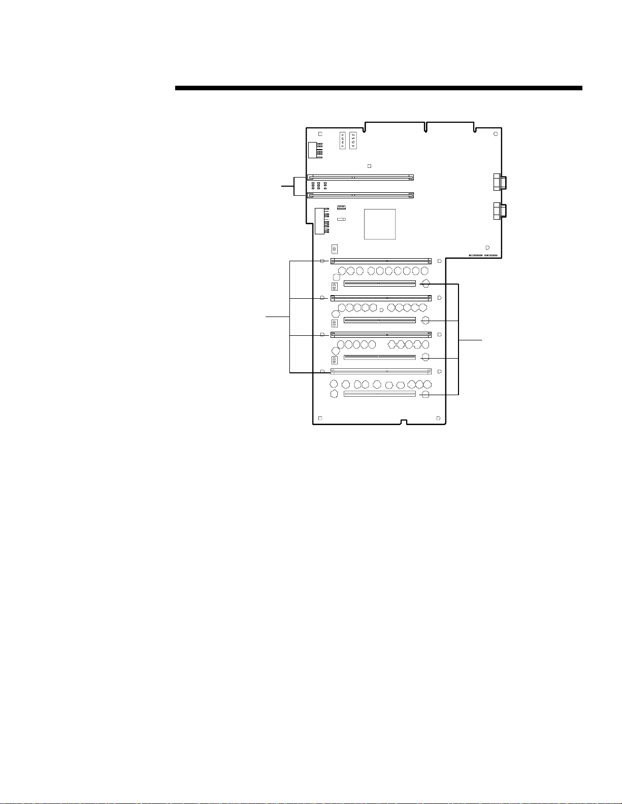
Processor Board
The p rocessor board (F i gure 2 ) ha s four sockets for Pentium II Xeon p rocessor s, four sock ets for
redundant processor power modules, and two slots for memory expansion boards. The redundan t
processor power modules maintain the precise voltage requirements of the processors. The
memory expansion boards allow customers to scale system memory up to 8 GB. The ProLiant
7000 ships with one Pentium II Xeon processor, one redundant processor power module, and two
memory expansion boards. Processor terminator cards are also provided with the server. A
processor terminator card mus t rem ain in ea ch pr ocess or socket not occupi ed by a processor.
Memory Expansion Boards
The ProLiant 7000 ships with t wo memory expansion boards instal l ed on th e pr ocessor board. As
shown in Figur e 3, each memory expansion board has si x teen m emory sockets ( four ban ks of four
sockets) for Dual In-Line Memory Modules, or DIMMs. The DIMMs must be installed in sets of
(cont.)
1
Redundant
Processor Power
Module Sockets
Figure 2: Processor Board.
Page 8

ECG078/0698
ECHNOLOGY BRIEF
T
.
.
four, and each DIMM in a given bank must be the same size, type, and speed. The ProLiant 7000
.
.
.
memory expansion board has the following features:
.
.
.
.
.
.
.
.
.
.
.
.
.
.
.
.
.
.
.
.
.
.
.
.
.
.
.
.
.
.
.
.
.
.
.
.
.
.
.
.
.
.
.
.
.
.
.
.
.
.
.
.
.
.
.
.
.
.
.
.
.
.
.
.
.
.
.
.
.
.
.
.
.
.
.
.
.
.
.
.
.
.
.
.
.
.
.
.
.
.
.
.
.
.
.
.
.
.
.
.
.
.
.
.
.
.
.
.
.
.
.
.
.
.
.
.
.
.
.
.
.
.
.
.
.
.
.
.
.
.
.
.
.
.
.
.
.
.
.
.
.
.
.
.
.
.
.
.
.
.
.
.
8
Error Checking and Correcting (ECC) Memory with single-bit error correction and detection
•
down to a single DIMM, and multi-bit error detection down to the memory bank.
Extend ed Da t a Out (EDO)
•
Expandable to 8 GB (2 memory expansion boards x 16 DIMMS x 256-MB/DIMM).
•
Peak data transfer rate of 1.6 GB/s
•
Concurrent C PU-to-memory and PC I-to-m emory accesses.
•
Banks
1
2
3
4
Figure 3: Bank designations and DIMM socket numbers on Memory Expansion Board.
The peak memory transfer rate of 1.6 GB/s supports the maxi mum da ta rates on the processor bus
(800 MB/s) and PCI buses (532 MB/s) concurrently, using industry standard ECC EDO DIMMs.
Each memory board con tains four ba nks of 4: 1 int erlea ved DIMMs. Acces ses to bank s of
memor y on the m emory board are over lapped using Add ress Bit P ermutin g ( A BP) . Accesses t o
banks of memory that reside on separate boards are overlapped using Card to Card (C2C)
interleaving. The ABP and C2C interleaving features are automatically enabled when banks of
memory are populated with the same type of DIMMs.
I/O Board
The I/O board (Figure 4) has ten expansion slots an d three 33-MHz PCI buses:
Five 64-bit PCI Hot Plug slots (PCI Bus 3)
•
Four 32-bit PCI Hot Plug slots (PCI Buses 1 and 2)
•
One ISA modem slot
•
The five 64-bit PCI expansion slots on PCI Bus 3 include three PCI Hot Plug slots and two PCI
Hot Plug slots with extended SCSI. All 32-bit PCI adapters work in any of the five 64-bit
expansion slots, and all 64-bit adapters work in the 32-bit expansion slots. In addition, the two
extended PCI slots allow the Smart Ar ray 3100ES Controller to route three SCSI buses to the I/O
1
For more information on Compaq’s memory technology, see technology brief
Technology Evolution
(cont.)
1
, 60-ns DIMMs in 16-, 32-, 64-, 128-, a nd 256-MB sizes.
, document number 518A/0697.
Sockets
1
2
3
4
5
6
7
8
9
10
11 12
14
13
16
15
Memory
Page 9

ECG078/0698
ECHNOLOGY BRIEF
T
.
.
board (slot 10/11 SCSI ports 1, 2, and 3) where the buses are cabled to the thr ee int ernal drive
.
.
.
cages. This eliminates cabling between the controller and I/O board.
.
.
.
.
.
Slots 5 and 6 on PCI Bus 2 are shared with an embedded dual-chann el SCSI controller (SCSI
.
.
.
ports 2 and 3). Slots 3 and 4 on PCI Bus 1 are shar ed with the Standard Peri pheral Board.
.
.
The aggregate peak data transfer rate across the th ree PCI buses is 532 MB/s. Because of the
.
.
.
high bandwidth of the three PCI buses, PCI bus load balancing is not required.
.
.
.
.
.
The s ystem in terl ocks p rovide a closed-loop checking mechanism for verifying proper com p onent
.
.
.
mating and cabling interconnects between critical server components. Three LEDs on the I/O
.
.
.
board can be used to isolate improperly mated components. To protect critical components, the
.
.
.
server will not power up if the interlock is broken.
.
.
.
.
.
.
.
.
.
.
.
.
.
.
.
.
.
.
.
.
.
.
.
.
.
.
.
.
.
.
.
.
.
.
.
.
.
.
.
.
.
.
.
.
.
.
.
.
.
.
.
.
.
.
.
.
.
.
.
.
.
.
.
.
.
.
.
.
.
.
.
.
.
.
.
.
.
.
.
.
.
.
.
.
.
.
.
.
.
.
.
.
.
.
.
.
.
.
.
.
.
.
.
.
.
.
.
.
.
.
.
.
.
.
.
.
.
.
.
.
.
.
.
.
.
9
Slot 10/11
SCSI Ports
1, 2, 3
64-bit PCI Hot Plug
with Extended SCSI
(cont.)
11
64-bit PCI
Hot Plug
98
10
PCI
Bus 3
32-bit PCI
Hot Plug
5
6
PCI
Bus 2
7
Figure 4: I/O Board.
4
PCI
Bus 1
ISA Modem
Slot
3
2
Standard
1
Peripheral
Board Slot
SCSI Port 2
SCSI Port 3
System Interlock
LEDs
Page 10

ECG078/0698
ECHNOLOGY BRIEF
T
.
.
Standard Peripheral Board
.
.
.
.
.
The Standard Peripheral Board (Figur e 5) contain s ASICs (among th em four Compaq-designed
.
.
.
ASICs) to provide connections for all system management and legacy components. This includes
.
.
conn ectors for the m ous e, keyboard, IDE C D-ROM, diskett e d rive, vi d eo, parallel devices , SCSI
.
.
.
devices, and Integrated Management Display (IMD). The system ROM, configuration switch,
.
.
.
and battery for CMOS are also located on this board.
.
.
.
.
.
.
.
.
.
.
.
.
.
Diskette Drive
.
.
Con ne cto r
.
.
.
.
.
.
.
.
.
.
IDE C D-R OM
.
.
Connector
.
.
.
.
.
.
.
.
.
.
.
.
.
.
.
.
.
.
.
.
.
.
.
IGH-AVAILABILITY TECHNOLOGIES
H
.
.
.
.
Industry tolerance of server downtime continues to decr ease as compan ies become more global,
.
.
.
decent ral ized, an d aware of down time costs. A 1996 study
.
.
.
1000 companies require recovery from failur e in l ess than thr ee minut es. The ProLiant 7000
.
.
.
answers the demand for h igh availability by incorporating the following features into the server
.
.
.
hardware:
.
.
.
.
.
.
.
.
.
.
.
.
.
.
.
.
.
.
.
.
.
.
.
.
.
.
.
.
.
.
.
.
.
.
.
.
.
.
.
.
.
.
.
.
.
.
.
.
.
.
.
.
.
.
.
.
.
.
.
.
.
.
.
.
.
.
.
.
.
.
.
.
.
10
Redundant network interface contr oller technology
•
Redundant, hot-plug fans
•
Redundant processor power m odules
•
Redundant, hot-plug power supplies
•
Hot-plug drives
•
Compaq Smart Arr a y 3100ES Controller
•
PCI Hot Plug technology for PCI adapters
•
Redundant compon ents ensure that the server is highly fault-tolerant. In many cases, if a power
supply, fan, processor power module, or I/O board fails, the redundant standby component can
take over operation with no down time to the server . With th e addition of hot-plug capabilities,
server downtime can be eliminated while components are being replaced, added, or upgraded.
2
Demand Assessment Requirements Tracking Study, Executive Summar y, The Standish Group
Interna t iona l , 1996.
(cont.)
IMD Connector
Figure 5: Standard Peripheral Board.
SCSI Port 1
SCSI Port
Pa r all el
Connector
Video
Connec tor
Mouse
Connector
Key board
Connector
2
found that 37 percent of Fortune
Page 11

ECG078/0698
ECHNOLOGY BRIEF
T
.
.
.
Redundant Network Interface Controller Technology
.
.
.
.
Compaq’s Redundant Netelligen t NIC technology allows two similar NICs to share a single
.
.
.
ins tan ce of devi ce d river code. One NIC becomes the a ctive n etwork control ler a nd the oth er NIC
.
.
.
acts as a standby controller. If the active NIC fails, the network traffic can be switched
.
.
.
automatically to the standby NIC. This redundancy eliminates the NIC or cable as a single poin t
.
.
.
of failure. With PCI Hot Plug technology, the failed NIC can be r eplaced without shutting down
.
.
.
the s ystem. Thus, the end-user can have conti nuous service a nd the admin istrator can g reat ly
.
.
.
reduce both planned and unplanned downtime.
.
.
.
.
.
.
.
.
.
.
.
.
.
.
.
.
.
.
.
.
.
.
.
.
.
.
.
.
.
.
.
.
.
.
.
.
.
.
.
.
.
.
.
.
.
.
.
.
.
.
.
.
.
.
.
.
.
.
.
.
.
.
.
.
.
.
.
.
.
.
.
.
.
.
.
.
.
.
.
.
.
.
.
.
.
.
.
.
.
.
.
.
.
.
.
.
.
.
.
.
.
.
.
.
.
.
.
.
.
.
.
.
.
.
.
.
.
.
.
.
.
.
.
.
.
.
.
.
.
.
.
.
11
Softwa re that supports a r edunda nt NIC configuration is available on the Compaq Support
Note:
Software CD that ships with the server.
The ProLiant 7000 supports a Netelligent dual-port 10/100 TX PCI Network Interface Controller
(NIC). The NIC has two ports for 10BaseT or 100TX Ethernet. The ports are seen as two
separate local area networks LANs, bot h supporting full-duplex Ether net (20 Mb/s) and Fast
Ethern et (200 Mb/s). If only one of the ports is used, a terminator pl ug is provided for the unused
port. Redundancy is also available across the two ports with one NIC.
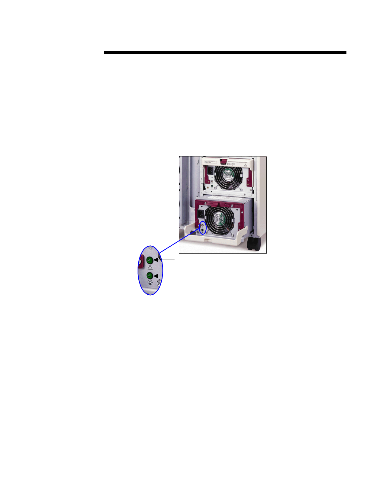
Redundant Hot-Plug Fans
The ProLiant 7000 ha s two primar y hot-plug fans (externa l) a nd two redundant fans (int er nal) for
the processor and memory section. The pair of primar y hot-plug fan s for the processor and
memory section is en closed in a single fan unit (Figure 6). The primary hot-plug fans spin under
rotor con tr ol; while the internal, redundant fans spin freely in the server airflow because they are
not required for cooling. Should the primary fan unit fail, the redundant fans start automatically.
The hot-plug primary fan unit can be easily removed by means of a single thumbscrew. The hotplug LEDs indicate the status of the fans: Green indicates the fans are function ing properly, and
amber indicates the fans have failed.
Figure 6: Hot-plug (external) primary fan unit for the processor and memory section.
(cont.)
Thumbscrew
for removal
Hot-Plug
LEDs
Fan Unit
Page 12

ECG078/0698
ECHNOLOGY BRIEF
T
.
.
.
.
The server also has one primar y hot-plug fan and one r edun dant hot-plug fan for the I/O board in
.
.
.
the upper section of the server (Figure 7). Should th e pr i ma ry fan fail, the redundant fan will
.
.
.
start automatically.
.
.
.
.
.
.
.
.
.
.
.
.
.
.
.
.
.
.
.
.
.
.
.
.
.
.
.
.
.
.
.
.
.
.
.
.
.
.
.
.
.
.
.
.
.
.
.
.
.
.
.
.
.
.
.
.
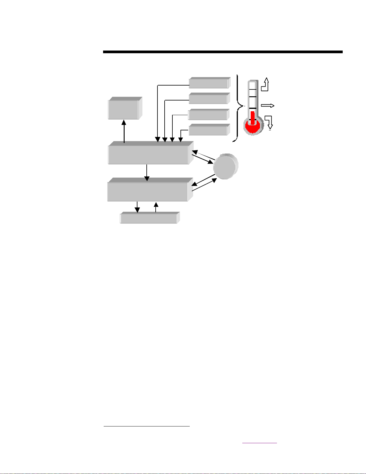
The s erver fa n cont rol l ogic operates independen t of the system process or and oper ating system
.
.
.
(OS). Regardless of the OS that is running or its condition, the fan control logic an d th e server
.
.
.
temperature mon itoring circuitry work together to cool the server effectively.
.
.
.
.
The fans have two speed s: normal and high. Un d er typical circums t ances, th e normal fa n speed
.
.
.
is sufficient to cool up to four processors, eighteen h a rd disk drives, and ten I/O expan sion boards.
.
.
.
As a precaution against increases in ambient air or localized internal temperatures, Compaq has
.
.
.
established three thermal trip points, as shown in Figure 8. When the first thermal trip point is
.
.
.
reached, the fans adjust automatically to high speed to increase cooling.
.
.
.
.
.
User s can select whether to enable the following server response to the second thermal trip point.
.
.
If th e int ernal air t emperature exceeds t he second tr ip point, the OS initiates a controlled
.
.
.
shutdown of the server. Simultaneously, a warning message is sent to the IMD and Compaq
.
.
.
Insight Manager. The server restarts automatically when it has cooled sufficiently.
.
.
.
.
.
Finally, in the unlikely event server temperature con tin ues to rise, a third trip point shuts down
.
.
.
the power supplies to protect critical components from overheating. The server restarts
.
.
.
automatically when it has cooled sufficiently.
.
.
.
.
.
.
.
.
.
.
.
.
.
.
.
.
.
.
.
.
.
.
.
.
.
.
.
.
.
.
.
.
.
.
.
.
.
.
.
.
.
.
.
.
.
12
(cont.)
Redundant
Hot-Plug
Fan
Figure 7: Hot-plug fans for the I/O section.
Primary
Hot-Plug
Fan
Failed
Failed
(Amber)
(Amber)
LEDs
OK
OK
(Green)
(Green)
Page 13
e
y
•
•
•
d
s
ECG078/0698
ECHNOLOGY BRIEF
T
.
.
.
.
.
.
.
.
.
.
.
.
.
.
.
.
.
.
.
.
.
.
.
.
.
.
.
.
.
.
.
.
.
.
.
.
.
.
.
.
.
.
.
.
.
.
.
.
.
.
.
.
.
.
.
.
.
.
.
.
.
.
.
.
.
.
.
.
.
.
.
.
.
.
.
.
.
.
.
.
.
.
.
.
.
.
.
.
.
.
.
.
.
.
.
.
.
.
.
.
.
.
.
.
.
.
.
.
.
.
.
.
.
.
.
.
.
.
.
.
.
.
.
.
.
.
.
.
.
.
.
.
.
.
.
.
.
.
.
.
.
.
.
.
.
.
.
.
.
.
.
.
.
.
.
.
.
13
Power
Supplies
Temperature Monitoring
Circuitry
Fan Control Logic
System Fans
Redundant Processor Power Modules
Each processor in the ProLiant 7000 h a s its own redunda nt processor power m odule (PPM).
PPMs are also known as volt a ge regulat or m odules. The PPMs deliver the precise voltage
requirements of the processors. The core voltage for the 400-MHz Pentium II Xeon processor is
2.0 V and th e voltage for the cache is 2.5 V.
Compaq PPMs are programmable and support all current and futur e versions of Slot 2 processors.
Each PPM module has redundant circuitry. If a failure occurs in one circuit of the module, the
other circuit automatically takes over th e task of regulating power to the processor.
The ProLiant 7000 ships standard with one redundant PPM. An additional redundant PPM is
available in each processor option kit.
Redundant Hot-Plug Power Supplies
The ProLiant 7000 uses one of the newest Compaq technologies to r educe downtime: intelligent,
redundant , hot-plug power supplies. The server ships stan da rd with two, dual-rated 750 W/500
W power supplies and supports thr ee power supplies for an n + 1 redundant configurati on. The
power supplies are connected to a separate power backplane in the server. Even if a power supply
fails, its internal fans will continue to operate and help cool the server.
The power supply has an embedded microcontroller and an Inter-Integra t ed Cir cuit (I
communicates the status back to the system h ealth drivers.
information to th e IMD and to Compaq Insight Manager.
3
For additional details about Compaq’s intelligent power supplies, see the technology brief
Intelligent Powe r Supply Technology,
(cont.)
- Hardware shutdown
•
Temperature Sensors
System Boards
Ambient Probe
Power Supplies
Processors
Har
- Restart when cool
•
Re
•
Sp
- Speed up fans
•
S
OS
Figure 8: Schematic diagram of fan control logic .
3
The health drivers then send status
document number ECG016/0198
- Graceful OS shutdown
- System alert
- Restart when cool
2
C) bus that
.
Page 14
ECG078/0698
ECHNOLOGY BRIEF
T
.
.
The microcontroller performs the following functions:
.
.
.
.
.
•
Self-test
.
.
.
.
.
.
.
.
.
.
.
.
.
.
.
.
.
.
.
.
.
.
.
.
.
.
.
.
.
.
.
.
.
.
.
.
.
.
.
.
.
.
.
.
.
.
.
.
.
.
.
.
.
.
.
.
.
.
.
.
.
.
.
.
.
.
.
.
.
.
.
.
.
.
.
.
.
.
.
.
.
.
.
.
.
.
.
.
.
.
.
.
.
.
.
.
.
.
.
.
.
.
.
.
.
.
.
.
.
.
.
.
.
.
.
.
.
.
.
.
.
.
.
.
.
.
.
.
.
.
.
.
.
.
.
.
.
.
.
.
.
.
.
.
.
.
.
.
.
.
14
temperature, RAM integrity, ROM ver sion, analog-to-digital conver sion accuracy, and nonvolatile memory integrity of the power supply.
•
Auto Line Sensing
(at 110V), a lin e-sensing feature automati call y recognizes which line voltage is connected.
The user does not need to configure the supply for voltage.
•
LED Standby Controls
(LEDs) on the back of the power supply that indicate AC an d DC power status, as shown in
Figure 9. This gives the user vital status infor mation at a glance.
- The intelligent power supplies perform their own power-on self-test that checks
(cont.)
- Because the power supplies are rated for both 750W (at 220V) and 500W
- The microcontroller also drives two status light-emitting diodes
Green - AC power good
Clear - AC power not good
Clear - Front panel power switch off or open interlock
Flashing Green - Power on delay or software power off
Green - Outputs on and good
Flashing Amber - Failed self test
Amber - Outputs failed
Flashing Amber/Green - Restart failed
Figure 9: Power supply LED status indicators.
Page 15

ECG078/0698
ECHNOLOGY BRIEF
T
.
.
Power Down Controls
.
.
.
.
.
As shown in Figure 10, the server power switch connects to the microcontroller rather than
.
.
.
directly to the power lin e. This means that turning off the power switch does not turn off power
.
.
instantly. Instead, th e microcontroller communicates with th e system board and the OS by way of
.
.
.
.
.
.
.
.
.
.
.
.
.
.
.
.
.
.
.
.
.
.
.
.
.
.
.
.
.
.
.
.
.
.
.
.
.
.
.
.
.
.
.
.
.
.
.
.
.
.
.
.
.
.
.
.
.
.
.
.
.
.
.
.
.
.
.
.
.
.
.
.
.
.
.
.
.
.
.
.
.
.
.
.
.
.
.
.
.
.
.
.
.
.
.
.
.
.
.
.
.
.
.
.
.
.
.
.
.
.
.
.
.
.
.
.
.
.
.
.
.
.
.
.
.
.
.
.
.
.
.
.
.
.
.
.
.
.
.
.
.
.
.
.
.
15
2
C bus. The power down cont rols ca n be config ured in one of three ways:
the I
Secure Mode - Power supply will not shut down if power switch is flipped.
•
Delay Mode - Power supply will shut down after a 10-second delay. This allows time to
•
reactivate th e switch if it was mistakenly flipped.
Graceful Shut Down - A 10-second delay counter begins as a message warning of an
•
imminent power-down goes to Compaq Insight Manager and the IMD. Because of the
communication between th e microcontroller and the OS, the OS can delay the power down
until all running applications have pr operly closed. Should the OS not be runn in g, the power
goes down when the delay counter expires.
The power down control feature is supported under Microsoft Windows NT 4.0. Both Novell and
SCO are planning to implement the power down control in the future.
OS
Load Balancing
The power supplies automatically load balan ce to within 10 per cent of the average current of all
supplies. Before the power com es up, the master power supply m a tch es its output load rai ls to
those of the other power supplies so that the load is automatically balan ced across all power
supplies. If one supply fails, the load balancing feature allows the other supplies to pick up the
remaining power load quickly.
Power Factor Correction
Compaq’s intelligent power supplies have built-in power factor correction to synchr onize the
voltage and current phases. This ensures maximum power is available. It also reduces the return
current in the ground line, wh ich r educes the overall power consumption.
(cont.)
System
Board
Power Supply
Power
Backplane
Power
Switch
Figure 10: Power supply schematic.
DC
I2C Bus
Power On
Soft Power Down
AC/DC
Converter
Microcontroller
AC
Page 16

ECG078/0698
ECHNOLOGY BRIEF
T
.
.
Hot-Plug Capability
.
.
.
.
.
When a power supply is hot swapped, the microcontroller governs the power-up and power-down
.
.
.
sequen ces, enables the health drivers to calculate redundancy “on the fly,” and informs the health
.
.
drivers of changes in load. Compaq hot-plug power supplies are readily iden tifiable by their port-
.
.
.
colored bezel, as shown in Figure 11.
.
.
.
.
.
.
.
.
.
.
.
.
.
.
.
.
.
.
.
.
.
.
.
.
.
.
.
.
.
.
.
.
.
.
.
.
.
.
.
.
.
.
.
.
.
.
.
.
.
Hot-Plug Hard Disk Drives
.
.
.
.
The ProLiant 7000 ha s three intern a l drive cages for hot-plug drives. Each removable drive cage
.
.
.
holds either six 1-inch drives or four 1.6-inch drives or a combination of both. This gives users
.
.
.
the flexibility to configure the server for either maximum number of spindles or maximum
.
.
.
storage capacity. Maximizing the number of spindles reduces overall capacity, but it increases
.
.
.
perfor man ce in database or other disk-intensive applications. When the server is configured for
.
.
.
maximum capacity, it can hold 218 GB of storage (12 drives x 18.2 GB per 1. 6-i nch drive =
.
.
.
218.4 GB). When configured for maximum number of spindles, the server can hold 163.8 GB
.
.
.
(18 drives x 9.1 GB per 1-inch drive = 163.8 GB).
.
.
.
.
.
.
Compaq Smart Array 3100ES Controller
.
.
.
.
.
The Compaq Smart Array 3100ES controller4 is a 3-channel, Wide-Ultra SCSI-3 controller that
.
.
.
ships standard in th e ProLiant 7000. T he architecture of the Smart Array 3100ES improves on
.
.
.
the Compaq SMART-2 Array Controller by:
.
.
.
.
.
.
.
.
.
.
.
.
.
.
.
.
.
.
.
.
.
.
.
.
.
.
.
.
.
.
.
.
.
.
.
.
.
.
.
.
.
.
.
.
.
.
.
.
.
.
.
16
Simplifying SCSI cabling configuration.
•
- The extended SCS I connect or rou tes th ree SCSI bu ses .
- Three Wi d e- Ul tra SCSI-3 bus es are routed t o the server’s three in ternal d rive ca g es .
Improving serviceability through PCI Hot Plug capabilities.
•
Increasi ng perform ance wit h 64 MB of removable, battery-backed ca che boar d ( 56 MB for
•
read/wri te cach e) .
Allowing all three d rive cag es to be configu red as one cont i guous RAID.
•
Faster processor memory
•
Future support for controller redundan cy
•
4
For more information, see tech n ology brief
document number ECG079/0698.
(cont.)
Port-colored bezel
Figure 11: Front view of power supply with port-colored bezel.
Compaq Smart Array Controller Technology
,
Page 17

ECG078/0698
ECHNOLOGY BRIEF
T
.
.
.
PCI Hot Plug Technology for PCI Adapters
.
.
.
.
The Compaq ProLiant 7000 and ProLiant 6500 servers are the first standa rds-based servers to
.
.
.
incorporate industry-standard PCI Hot Plug technology. This technology, pioneered by Compaq,
.
.
.
adds hot-plug capabilities to existing PCI adapters for increased system availability and
.
.
.
serviceability. Compaq led the industry by licensing its PCI Hot Plug implementation to In tel,
.
.
.
thu s broadenin g customer access to this sta ndard techn ol ogy.
.
.
.
.
Compaq’s implementation of PCI Hot Plug differs from implementations by other vendors
.
.
.
whereby several slot s are powered down a t once or an entire PCI bu s is powered d own . Compaq
.
.
.
incorporated el ectronics into the ser ver to control each PC I Hot Plug sl ot ind ividua lly, so that a
.
.
.
single slot can be powered down without affecting the oper ation of the other slots.
.
.
.
.
.
Compaq’s implementation of the PCI Hot Plug standard allows the following capabilities while
.
.
.
the system is running:
.
.
.
.
•
Hot replacement
.
.
.
.
•
Hot upgrade
.
.
.
.
.
•
Hot expansion
.
.
.
.
The ProLiant 7000 is designed to support all thr ee hot-plug capabilities for all 64-bit and 32-bit
.
.
.
PCI Hot Plug slots. These capabilities can be added incrementally, depending on the OS
.
.
.
implementation.
.
.
.
.
For more information about major OS vendors that support PCI Hot Plug, refer to the following
.
.
.
technology briefs:
.
.
.
.
.
•
PCI Hot Plug Technology
.
.
.
.
•
PCI Hot Plug Technology with Novell Archit ec t ure
.
.
.
.
.
•
PCI Hot Plug Technology with SCO Software Architecture
.
.
.
.
•
Deployi ng PCI Hot Plug on Compaq Servers in a Microsoft Windows NT Environment
.
.
.
.
.
.
.
.
.
.
.
.
.
.
.
.
.
.
.
.
.
.
.
.
.
.
.
.
.
.
.
.
.
.
.
.
.
.
.
.
.
.
.
.
.
.
.
.
.
.
.
.
.
.
.
.
.
.
.
.
.
.
.
.
.
.
.
.
.
17
document number 064A/0797
PCI Hot Plug technology is backward compatible with existing industry-standard adapters. While
new drivers are required to implemen t h ot-plug capabilities, no changes are required to the vast
majority of existing adapters. These leading independent hardware suppliers are committed to
modifying their device drivers to be h ot-plug aware: Adaptec, AMI, Dialogic, Digi International,
Madge, Mylex, QLogic, Stan dard Microsystems Corporation, SysKonnect, and 3Com. In
addition, Compaq is delivering hot-plug capable drivers for its own leading PCI adapters.
PCI Hot Plug Electronics
Compaq’s pr imar y electronic component is the PCI Hot Plug controller, which performs the
following essential tasks:
•
PCI Bus Control
electrically isolate any single PCI slot from the rest of the system. Isolating a single slot
allows replacement of an adapter without in terr upting the server or other active adapters.
•
Power Contro l
a single PCI slot. To perform this function, the controller uses slot-specific power control
electronics . Th e power-control electr onics a l low proper power seq u encing on the PC I bu s
and guarantee safe con trol of th e power to the individual PCI adapters.
(cont.)
—replacing a single PCI adapter with a similar adapter
—replacing a PCI adapter with an upgraded adapter
—adding a PCI adapter to an empty slot
, document number ECG080/0698
, document number ECG081/0698
, document number ECG082/0698
- The hot-plug controller communicates with devices on the PCI bus to
- The controller receives a comm and from the OS to p ower - up or p ower - d own
,
Page 18

ECG078/0698
ECHNOLOGY BRIEF
T
.
.
All slots have a new push-button control (the PCI Hot Plug Button) that allows slot control at the
.
.
.
server . Like other hot-plug components in the ser ver, the PCI Hot Plug Buttons are port-colored
.
.
.
as shown in Figure 12.
.
.
.
.
.
.
.
.
.
.
.
.
.
.
.
.
.
.
.
.
.
.
.
.
.
.
.
.
.
.
.
.
.
.
.
.
.
.
.
.
.
.
.
.
.
.
.
.
.
.
.
If the green PCI Hot Plug LED for the slot is on, pushing the PCI Hot Plug Button will stop all
.
.
.
activity to the slot and allow any cach ed data to be cleared before the power to the slot is
.
.
.
interrupted. While the slot powers down, th e green LED blinks. The green LED will turn
.
.
.
completely off when it is safe to open the slot release lever and remove the PCI adapter. Once the
.
.
.
PCI adapter has been replaced, push ing the PCI Hot Plug Button will reactivate the slot.
.
.
.
Alternatively, these same operations can be performed by using the PCI Hot Plug software
.
.
application.
.
.
.
.
.
.
Mechanical Design
.
.
.
.
.
Compaq designed the ProLiant 7000 system chassis for safe and easy installation and r emoval of
.
.
.
PCI adapters. The ProLiant 7000 h a s n i ne PCI Hot Plug slots—five 64-bit slots and four 32-bit
.
.
.
slots.
.
.
.
.
The hot-plug slots are spaced wide enough to allow users to remove and replace adapters without
.
.
.
electrically contacting (sh orting) other compon ents. Flexible slot separators are also used
.
.
.
between the hot-plu g s lots to reduce the r isk of electrica l shorting. O n top of the ser ver chassis, a
.
.
.
lockabl e access door over th e hot-p lug slots allows an a dminist rat or easy access t o hot-plug
.
.
.
adapters.
.
.
.
.
.
.
.
M
.
.
.
.
Fault-tolerant, redundant features are only part of what makes Compaq servers highly available.
.
.
.
Compaq also integrates management tools into the server hardware to improve availability and
.
.
.
reduce down time. The Integrated Management Display (IMD) and Integrated Remote Console
.
.
.
(IRC) p rovide essenti al information at a gla nce and al low users easy remote access to their
.
.
.
server s. In addition to these management technologies, the auto-default ROM configuration
.
.
.
provides default con figuration settings for most devices.
.
.
.
.
.
.
.
.
.
.
.
.
.
.
.
.
.
.
.
.
.
.
18
Figure 12: PCI Hot Plug Buttons for ProLiant 7000 (top view of I/O section).
ANAGEMENT TECHNOLOGIES
(cont.)
PCI Hot Plug Button
Slot Release Lever
Page 19

ECG078/0698
ECHNOLOGY BRIEF
T
.
.
.
Integrated Management Display
.
.
.
.
The IMD (Figure 13) is a backlit liquid crystal display (LCD) that allows administrators to enter
.
.
.
server and contact information. Just as importantly, the IMD displays critical information,
.
.
.
warning messages, and er ror messages in an easy-to-understand format.
.
.
.
.
.
.
.
.
.
.
.
.
.
.
.
.
.
.
.
.
.
.
.
.
.
.
.
.
.
.
.
.
.
.
.
.
.
.
.
.
.
.
.
.
A 5V auxiliary power line supplies power to the IMD whenever the server power lin e is plugged
.
.
.
in. Even if the server power goes down, the auxiliary line continues to power th e IMD so that
.
.
critical infor mation, such as the last error message and the administrator’s name, can be obtained.
.
.
.
.
.
The IMD unit contains its own static memory. Th is memory contains both the software code to
.
.
.
control the IMD and the text messages shown on the display. All software enhancements added
.
.
.
in the future will be available through a flash able ROMpaq. Also during POST, all event logs,
.
.
.
system infor mation, and administrator information upload from the system nonvolatile RAM.
.
.
.
During runtime, new events are stored in both the nonvolatile RAM and the IMD SRAM. If the
.
.
.
IMD unit is removed and replaced, all key event and system information is still available.
.
.
.
.
.
.
Integrated Remote Console
.
.
.
.
IRC consists of a Compaq-designed Application Specific Integrated Circuit (ASIC) and associated
.
.
.
firmware. IRC allows out-of-band, or asynchronous, management capabilities such as remote
.
.
.
console and remote reset. These capabilities are indepen dent of the state of the network OS.
.
.
.
With IRC, an a d min istrator ha s full tex t mode vid eo a nd keyboar d access even if the O S is down.
.
.
.
The administrator has the ability to access the server, perform diagnostics, reset the system, watch
.
.
.
the reset process remotely, and view r eset sequences, regardless of whether the OS is functional.
.
.
.
.
.
For more information about IRC, refer to the Compaq technology brief
.
.
.
Management with Integrated Remote Console,
.
.
.
.
.
.
Auto-Default ROM Configuration
.
.
.
.
When the s ystem is first powered on, the s ystem ROM detect s the unconfi g ured s tate of the
.
.
.
hardware and provides default configuration settings for most devices. By providing this
.
.
.
initialization, the system can run
.
.
.
normal
.
.
.
.
.
If th e u s er inserts a
.
.
prior to powering on the server, th e system ROM will boot using t ha t CD. If t he system ROM
.
.
.
does n ot detect on e of these CDs, the user will be prompted for the intended operating system.
.
.
.
The system will reboot if any operating syst e m-de pen dent con figura tions have change d with the
.
.
.
new oper ating system s election. If the selected oper ating system-depen dent configu rat ions a re the
.
.
.
.
.
.
.
19
Figure 13: Integrated Management Display with sample alert message.
SmartStart
(cont.)
document number 582A/1096
Diagnostics
and
System Configuration
System Configuration, Diagnostics
and other software applications before running the
applications.
11:21 AM
Fan Removed
Main System:
Fan ID: 2
, or
SmartStart
Remote Server
.
CD in the CD-ROM drive
Page 20

ECG078/0698
ECHNOLOGY BRIEF
T
.
.
same as the current configurations, the system will boot n ormally. The OS selection may be
.
.
.
changed d uring subse quent reboots .
.
.
.
.
.
.
.
ERVICEABILITY FEATURES
S
.
.
.
.
.
By providing eas y access to server compon ents, th e ProLiant 7000 design furt her reduces the
.
.
.
downtime associated with upgrades and field maintenance.
.
.
.
.
The processor board, memory boards, and the I/O boar d are mounted using lever-actuated quick-
.
.
.
release modules that allow tool-less replacement. In addition, the processor an d I/O boards are
.
.
.
separated in t he chassis so tha t each can be r eplaced indep endently (Fi g u re 14) .
.
.
.
.
The I/O board is located in the top of the chassis to allow easy access for adding or replacing I/O
.
.
.
boards. This is an important convenience for using the hot-plug slots.
.
.
.
.
.
The internal drive cages are separated into three units. Each drive cage unit can be removed by
.
.
.
sliding it out from the front of the server. Th is allows easy replacemen t of hot-plug drives as the
.
.
.
customer upgrades to next-generation drive technology.
.
.
.
.
.
.
.
.
.
.
.
.
.
.
.
.
.
.
.
.
.
.
.
.
.
.
.
.
.
.
.
.
.
.
.
.
.
.
.
.
.
.
.
.
.
.
.
.
.
.
.
.
.
.
.
.
.
.
.
.
.
.
.
.
.
.
.
.
.
.
.
.
.
.
.
.
.
.
.
.
.
.
.
.
.
.
.
.
.
.
.
.
.
.
.
.
.
.
.
.
.
.
.
.
.
.
.
.
.
20
Internal
Drive Cages
PROL
Customers require investment protection and a long l i fe for their servers. The ProLiant 7000 i s
engi neer ed to take advantag e of new technology such as th e P enti u m II Xeon process or an d to
allow a growth path for the future. Specifically, the ProLiant 7000 has been designed with the
flexibility to accommodate future needs for up to eight processors.
IANT
(cont.)
7000 U
I/O Board
Processor
Board
COMPACT
Figure 14: ProLiant 7000 chassis.
PGRADE PATH
Page 21

ECG078/0698
ECHNOLOGY BRIEF
T
.
.
The ProLiant 7000 Server provides investment protection by retaining essential system
.
.
.
components and the chassis serial n um ber. When customers upgrade pr eviously purchased
.
.
.
ProLiant 7000 Servers to a Pentium II Xeon four- or eight-processor (4- or 8-way) configuration,
.
.
.
they will leverage the following components:
.
.
.
.
.
.
.
.
.
.
.
.
.
.
.
.
.
.
.
.
.
.
.
.
.
.
.
.
.
.
.
.
.
.
.
.
.
.
.
.
.
.
.
.
.
.
.
.
.
.
.
.
.
.
.
.
.
The upgrade will reduce th e total cost of ownership over the lifetime of the server, including
.
.
.
administrative and hardware costs. Because many enterprise oper ating systems, application
.
.
.
software installations, and warranties are linked to the hardware serial number s, continuation of
.
.
.
the chassis serial number reduces administration costs.
.
.
.
.
.
The chassis design and replaceable componen t s of the ProLiant 7000 allow unprecedented
.
.
.
flexibility. Early engineering analysis shows that the Pentium II Xeon processor and the 100-
.
.
.
MHz bus it supports create more power and t hermal load tha n the current Pent ium Pr o-based
.
.
systems. In plan ning for the Pentium II Xeon processor and 4-way requirements, Compaq
.
.
.
engineered the ProLiant 7000 power supplies and chassis with “headroom” to accommodate this
.
.
.
additional load.
.
.
.
.
.
.
.
Power Supplies
.
.
.
.
The ProLiant 7000 design allows the intelligent power supplies to share the power load. With
.
.
.
three power supplies installed, there is enough power to run up to eight processors and still
.
.
.
maintai n redundan cy. In a r edunda nt configuration, th e supplies deliver up to 1500 W; while in a
.
.
.
nonredundant configuration, they deliver up to 2250 W of power. Th i s far exceeds typical power
.
.
.
configurations for SMP servers, which range in maximum power capabilities from 700 to 840 W.
.
.
.
.
.
.
Fan Cooling Capacity
.
.
.
.
.
The fans have also been designed with extra “headroom” to allow for future growth paths with
.
.
.
additional processors. As mentioned previously, the fans have both high- and low-speed settings.
.
.
.
Performance testing of the ProLiant 7000 shows that even in 35ºC ambient air with a ll four
.
.
.
processors loaded, the fans maintain adequate cooling inside the box while running at low speed.
.
.
.
The ex cellen t fan p erform ance a nd the extra room inside the chassi s p rovide a mple a irflow and
.
.
cooling to support a future upgra de to eight Slot 2 processors.
.
.
.
.
.
.
.
.
.
.
.
.
.
21
Chassis
•
Rack mounting kit
•
Serial number
•
Agency la bels
•
Power supplies
•
Memory DIMMs (4-way upgr a de onl y)
•
Hard disk drives and backplanes
•
Integrated Management Display
•
CD-ROM, tape, and floppy drives (4-way upgr ade only)
•
All PCI adapter boards
•
Keyboard
•
Monitor
•
(cont.)
Page 22

ECG078/0698
ECHNOLOGY BRIEF
T
.
.
.
Chassis Desi g n
.
.
.
.
The ProLiant 7000 chassis has been engineered with flexibility, expandability, and longevity in
.
.
.
mind. T he ch assis d esign features three key elem ents:
.
.
.
.
.
.
.
.
.
.
.
.
.
.
.
.
.
.
.
.
.
.
.
.
.
.
.
.
.
.
.
.
.
.
.
.
.
.
.
.
.
.
.
.
.
.
.
.
.
.
.
.
.
.
.
.
.
.
.
.
.
.
.
.
.
.
.
.
.
.
.
.
.
.
.
.
.
.
.
.
.
.
.
.
.
.
.
.
.
.
.
.
.
.
.
.
.
.
.
.
.
.
.
.
.
.
.
.
.
.
.
.
.
.
.
.
.
.
.
.
.
.
.
.
.
.
.
.
.
.
.
.
.
.
.
.
.
.
.
.
.
.
.
.
.
.
.
22
Extra space
•
Adaptable ca bi net d esign
•
Extra airflow
•
Pentium Pro processors are packaged in a pin-grid array (PGA) for m factor, while the Pentium II
Xeon processor from Intel has the new Single Edge Con tact (SEC) cartridge form factor. The
SEC cartridge and its associated heat sink are larger than the Pentium Pro PGA and require
significantly more room in the chassis. When designi ng the ProLiant 7000 chassis, Compaq
included enough room to accommodate the new Pentium II SEC cartr idge form factor and up to
eight processors.
The chassis design also h as the “headroom” to accommodate the additional airflow needed to cool
an 8-way Pentium II Xeon configuration. The fans are mounted on sheet metal inserts that can
easily be changed during th e 8-way upgrade to provide the additional thermal capacity required.
The ProLiant 7000 chassis design is extremely adaptable. As mentioned earlier, the chassis
features separate compartments for the processor and I/O, wh ich allow them to be replaced
independently. All the sheet metal surrounding essen tial components can be easily changed to
accommodate additional processors. This includes the processor board, the I/O board, and the I/O
slots.
Processor Board
The ProLiant 7000 processor board is placed on a sheet metal subpan, as shown in Figure 15.
The ProLiant 7000 Pentium Pr o-based servers can be adapted to a new Pentium II Xeon-based
system by simply removing the old subpan an d sliding the new subpan an d system board into the
existing space.
I/O Board
Like the proc essor board, t he I /O board mounts on a s ubpan. A new I/O boa rd and a new subp an
of the same or differ en t siz e can be added without a chassis change.
(cont.)
Subpan
Figure 15: Processor board and its corresponding subpan.
Processor
Board
Page 23

ECG078/0698
ECHNOLOGY BRIEF
T
.
.
I/O Slots
.
.
.
.
.
With the upgrade, the ProLiant 7000 I/O section will increase the I/O bandwidth to match the
.
.
.
hig her p rocessing bandwidt h. Beca u s e the I/O slots are defi ned by a pa nel i nser t rat her tha n soli d
.
.
sheet metal (Figure 16), the upgr ade can be accomplished easily by replacing the I/O panel
.
.
.
inserts.
.
.
.
.
.
.
.
.
.
.
.
.
.
.
.
.
.
.
.
.
.
.
.
.
.
.
.
.
.
.
.
.
.
.
.
.
.
.
.
.
.
.
.
.
.
.
.
.
.
.
.
.
.
.
.
.
.
.
.
.
.
.
.
.
.
C
.
.
.
.
.
As business requirements become more demanding, Compaq will continue to deliver servers that
.
.
meet t hose req uir ements and tha t can be ex p and ed to meet fut ure needs as wel l. The Pr oLi ant
.
.
.
7000 offers many hot-plug and redundant technologies that allow virtually continuous uptime for
.
.
.
all key server components. Customers can be confident of their investment in t he ProLiant 7000
.
.
.
because of its planned upgrade path to future 32-bit processor technology with up to eight
.
.
.
processors.
.
.
.
.
.
.
.
.
.
.
.
.
.
.
.
.
.
.
.
.
.
.
.
.
.
.
.
.
.
.
.
.
.
.
.
.
.
.
.
.
.
.
.
.
.
.
.
.
.
.
.
.
.
.
.
.
.
.
23
ONCLUSION
(cont.)
Removable I/O
Panel Inserts
Figure 16: I/O panel inserts can be replaced to upgrade serve r.
 Loading...