

Page 1

ProLiant 6400R
Maintenance and Service Guide
Third Edition (April 2000)
Part Number 401054-003
Spare Part Number 101978-003
Compaq Computer Corporation
Page 2

Notice
The information in this publication is subject to change without notice.
COMPAQ COMPUTER CORPORATION SHALL NOT BE LIABLE FOR TECHNICAL OR
EDITORIAL ERRORS OR OMISSIONS CONTAINED HEREIN, NOR FOR INCIDENTAL OR
CONSEQUENTIAL DAMAGES RESULTING FROM THE FURNISHING, PERFORMANCE, OR USE
OF THIS MATERIAL. THIS INFORMATION IS PROVIDED “AS IS” AND COMPAQ COMPUTER
CORPORATION DISCLAIMS ANY WARRANTIES, EXPRESS, IMPLIED OR STATUTORY AND
EXPRESSLY DISCLAIMS THE IMPLIED WARRANTIES OF MERCHANTABILITY, FITNESS FOR
PARTICULAR PURPOSE, GOOD TITLE AND AGAINST INFRINGEMENT.
This publication contains information protected by copyright. No part of this publication may be
photocopied or reproduced in any form without prior written consent from Compaq Computer Corporation.
© 2000 Compaq Computer Corporation.
All rights reserved. Printed in the U.S.A.
The software described in this guide is furnished under a license agreement or nondisclosure agreement.
The software may be used or copied only in accordance with the terms of the agreement.
Compaq, Deskpro, Fastart, Compaq Insight Manager, Systempro, Systempro/LT, ProLiant, ROMPaq,
QVision, SmartStart, NetFlex, QuickFind, PaqFax, ProSignia, registered United States Patent and
Trademark Office.
Neoserver, Netelligent, Systempro/XL, SoftPaq, QuickBlank, QuickLock are trademarks and/or service
marks of Compaq Computer Corporation.
Microsoft, MS-DOS, Windows, and Windows NT are registered trademarks of Microsoft Corporation.
Pentium is a registered trademark and Xeon is a trademark of Intel Corporation.
Other product names mentioned herein may be trademarks and/or registered trademarks of their respective
companies.
Compaq ProLiant 6400R Maintenance and Service Guide
Third Edition (April 2000)
Part Number 401054-003
Spare Part Number 101978-003
Page 3

About This Guide
Symbols in Text.........................................................................................................vii
Symbols on Equipment.............................................................................................viii
Compaq Technician Notes .........................................................................................ix
Where to Go for Additional Help............................................................................... ix
Integrated Management Display...........................................................................x
Telephone Numbers .............................................................................................x
Chapter 1
Illustrated Parts Catalog
Mechanical Parts Exploded View.............................................................................1-2
Mechanical Spare Parts List ..................................................................................... 1-3
System Components Exploded View ....................................................................... 1-4
System Components Spare Parts List....................................................................... 1-5
Contents
Chapter 2
Removal and Replacement Procedures
Electrostatic Discharge Information.........................................................................2-1
Symbols on Equipment.............................................................................................2-2
Preparation Procedures.............................................................................................2-3
Hot-Pluggable Components ..............................................................................2-3
Non-Hot-Pluggable Components ......................................................................2-3
Powering Down the Server................................................................................2-3
Server Warnings and Precautions......................................................................2-4
Top Access Panel .....................................................................................................2-5
Power On/Standby Switch........................................................................................2-6
Front Bezel ...............................................................................................................2-8
Hot-Plug Fans...........................................................................................................2-9
I/O Hot-Plug Fans ...........................................................................................2-10
Hot-Plug Dual Redundant CPU Fan Assembly...............................................2-11
External Rear Hot-Plug Redundant System Fan Assembly.............................2-12
Removable Media and Hard Drives .......................................................................2-12
Media Storage .................................................................................................2-13
Hot-Plug Hard Drives......................................................................................2-14
Ultra2 SCSI Simplex Board ...................................................................................2-16
Removable Media Assembly..................................................................................2-17
1.44-MB Diskette Drive..................................................................................2-18
24X or Higher Low-Profile CD-ROM Drive Adapter Board..........................2-19
24X or Higher Low-Profile CD-ROM Drive .................................................. 2-20
Page 4

iv Compaq ProLiant 6400R Maintenance and Service Guide
Removal and Replacement Procedures
continued
Cable Folding and Routing Diagrams .................................................................... 2-21
24X or Higher Low-Profile CD-ROM Cable..................................................2-21
Diskette Drive Cable .......................................................................................2-22
External Fan Cable..........................................................................................2-22
Power Supply Cable........................................................................................2-23
Power Supply Signal Cable............................................................................. 2-24
Hot-Plug Power Supply.......................................................................................... 2-25
Processors, Processor Terminator Modules, and Processor Power Modules..........2-26
Processor and Related Component Locations ................................................. 2-26
Processor .........................................................................................................2-27
Processor Power Module.................................................................................2-28
Processor Terminator Module.........................................................................2-29
Peripheral Board.....................................................................................................2-30
Memory .................................................................................................................. 2-31
Address Bit Permuting .................................................................................... 2-32
Memory Board ................................................................................................2-33
Dual Inline Memory Modules .........................................................................2-34
PCI Hot Plug Expansion Boards ............................................................................2-35
PCI Hot Plug Basket Insulator................................................................................2-39
PCI Hot Plug Switch/LED Board and Cable..........................................................2-40
Power Backplane Board Assembly ........................................................................2-40
Side Access Panel...................................................................................................2-44
System Board and Tray .......................................................................................... 2-44
AC Power Cord and Plug Assembly ......................................................................2-45
Replacement Battery ..............................................................................................2-49
Chapter 3
Diagnostics and Troubleshooting
Diagnostic Tools Utility Overview...........................................................................3-1
Default Configuration...............................................................................................3-4
Default Configuration Messages.......................................................................3-4
Inspect Utility....................................................................................................3-4
Utilities Access.........................................................................................................3-5
Running Compaq Utilities.................................................................................3-5
Power-On Self-Test..................................................................................................3-6
Error Messages of the Power-On Self-Test.......................................................3-7
Diagnostics Software..............................................................................................3-20
Steps for Diagnostics.......................................................................................3-21
100 – 199, Primary Processor Test Error Codes .............................................3-22
200 – 299, Memory Test Error Codes .............................................................3-23
300 – 399, Keyboard Test Error Codes ...........................................................3-23
400 – 499, Parallel Printer Test Error Codes...................................................3-24
500 – 599, Video Display Unit Test Error Codes............................................3-25
600 – 699, Diskette Drive Test Error Codes ...................................................3-26
1100 – 1199, Serial Test Error Codes .............................................................3-27
1200 – 1299, Modem Communications Test Error Codes .............................. 3-27
1700 – 1799, Hard Drive Test Error Codes.....................................................3-28
1900 – 1999, Tape Drive Test Error Codes.....................................................3-29
6000 – 6099, Compaq NIC Boards Test Error Codes ..................................... 3-29
6500 – 6599, SCSI Hard Drive Test Error Codes ...........................................3-30
6600 – 6699, SCSI/IDE CD-ROM Drive Test Error Codes............................3-30
6700 – 6799, SCSI Tape Drive Test Error Codes ...........................................3-31
8600 – 8699, Pointing Device Interface Test Error Codes..............................3-31
Page 5

Diagnostics and Troubleshooting
continued
Array Diagnostic Utility.........................................................................................3-31
Starting ADU...................................................................................................3-32
Integrated Management Log...................................................................................3-43
Multiple Ways of Viewing the Log.................................................................3-43
Event List ........................................................................................................3-45
Event Messages...............................................................................................3-45
Rapid Error Recovery.............................................................................................3-47
Automatic Server Recovery-2.........................................................................3-48
Server Health Logs..........................................................................................3-57
ASR-2 Integrated Management Log Messages...............................................3-57
Storage Fault Recovery Tracking.................................................................... 3-60
Storage Automatic Reconstruction..................................................................3-60
Network Interface Fault Recovery Tracking...................................................3-61
Memory Fault Recovery Tracking ..................................................................3-61
Remote Service Features ........................................................................................ 3-61
ROMPaq Error Recovery Options..........................................................................3-62
ROMPaq Disaster Recovery ...........................................................................3-62
Redundant ROM Image Recovery ..................................................................3-63
Compaq Insight Manager .......................................................................................3-64
Features ...........................................................................................................3-64
Compaq Insight Management Software Architecture .....................................3-65
Contents v
Chapter 4
Connectors, Switches, and LED Indicators
Connectors................................................................................................................4-1
Rear Panel Connectors ......................................................................................4-1
System Board Connectors .................................................................................4-3
Peripheral Board Connectors.............................................................................4-4
Power Backplane Board Connectors.................................................................4-5
Ultra2 SCSI Simplex Board Connectors ........................................................... 4-6
Switches ...................................................................................................................4-7
Maintenance Configuration Switchbank (SW1)................................................4-7
Processor Core Frequency Switches (SW2 and SW3) ......................................4-8
LED Indicators .........................................................................................................4-9
Hot-Plug Power Supply LED Indicators ...........................................................4-9
Hot-Plug Fan LED Indicators..........................................................................4-10
Front Bezel LED Indicators ............................................................................4-11
PCI Hot Plug Board LED Indicators...............................................................4-13
Hot-Plug Hard Drives......................................................................................4-15
Interlock LED Indicators.................................................................................4-16
Chapter 5
Physical and Operating Specifications
System Unit ..............................................................................................................5-2
Hot-Plug Power Supply............................................................................................ 5-3
Dual Inline Memory Modules (DIMMs)..................................................................5-4
1.44-MB Diskette Drive ...........................................................................................5-4
24X or Higher Low-Profile CD-ROM Drive ...........................................................5-5
NC3131 Fast Ethernet NIC 64 PCI Dual Base10/100 Controller.............................5-6
Hot-Plug Hard Drives...............................................................................................5-7
Index
Page 6

Page 7
This maintenance and service guide is a troubleshooting guide that can be used for reference
when servicing Compaq ProLiant 6400R servers.
IMPORTANT: The installation of options and servicing of this product shall be performed by individuals
who are knowledgeable of the procedures, precautions, and hazards associated with equipment
containing hazardous energy circuits.
Symbols in Text
These symbols may be found in the text of this guide. They have the following meanings.
About This Guide
WARNING: To reduce the risk of personal injury from electrical shock and hazardous energy
levels, only authorized service technicians should attempt to repair this equipment. Improper
repairs could create conditions that are hazardous.
WARNING: Text set off in this manner indicates that failure to follow directions in the warning
could result in bodily harm or loss of life.
CAUTION: Text set off in this manner indicates that failure to follow directions could result in
damage to equipment or loss of information.
IMPORTANT: Text set off in this manner presents clarifying information or specific instructions.
NOTE: Text set off in this manner presents commentary, sidelights, or interesting points of information.
Page 8
viii Compaq ProLiant 6400R Maintenance and Service Guide
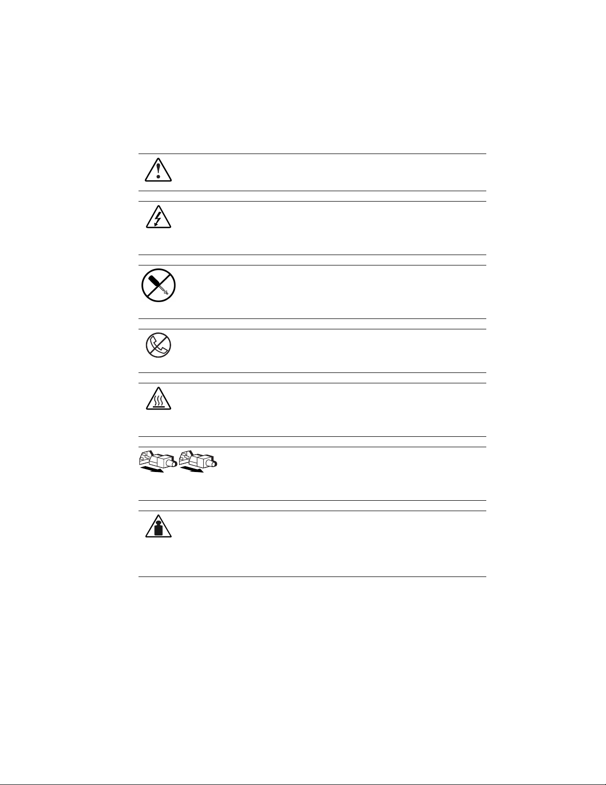
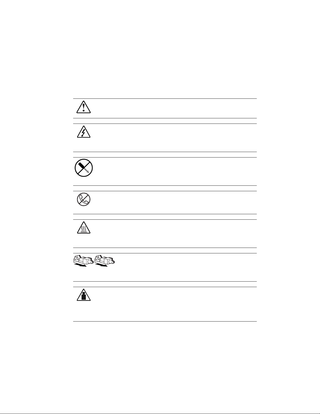
Symbols on Equipment
These symbols may be located on equipment in areas where hazardous conditions may exist.
This symbol in conjunction with any of the following symbols indicates the presence of a
potential hazard. The potential for injury exists if warnings are not observed. Consult your
documentation for specific details.
This symbol indicates the presence of hazardous energy circuits or electric shock hazards.
Refer all servicing to qualified personnel.
WARNING: To reduce the risk of injury from electric shock hazards, do not open this
enclosure. Refer all maintenance, upgrades, and servicing to qualified personnel.
This symbol indicates the presence of electric shock hazards. The area contains no user or
field serviceable parts. Do not open for any reason.
WARNING: To reduce the risk of injury from electric shock hazards, do not open this
enclosure.
This symbol on an RJ-45 receptacle indicates a Network Interface Connection.
WARNING: To reduce the risk of electric shock, fire, or damage to the equipment, do not
plug telephone or telecommunications connectors into this receptacle.
This symbol indicates the presence of a hot surface or hot component. If this surface is
contacted, the potential for injury exists.
WARNING: To reduce the risk of injury from a hot component, allow the surface to cool
before touching.
These symbols on power supplies or systems indicate the equipment is supplied
by multiple sources of power.
WARNING: To reduce the risk of injury from electric shock, remove all power
cords to completely disconnect power from the system.
This symbol indicates that the component exceeds the recommended weight for one
individual to handle safely.
WARNING: To reduce the risk of personal injury or damage to the equipment, observe local
34 kg
occupational health and safety requirements and guidelines for manual material handling.
75 lb
Page 9
Compaq Technician Notes
WARNING: Only authorized technicians trained by Compaq should attempt to repair this
equipment. All troubleshooting and repair procedures are detailed to allow only
subassembly/module level repair. Because of the complexity of the individual boards and
subassemblies, no one should attempt to make repairs at the component level or to make
modifications to any printed wiring board. Improper repairs can create a safety hazard. Any
indications of component replacement or printed wiring board modifications may void any
warranty.
WARNING: To reduce the risk of personal injury from electrical shock and hazardous energy
levels, do not exceed the level of repair specified in these procedures. Because of the
complexity of the individual boards and subassemblies, do not attempt to make repairs at the
component level or to make modifications to any printed wiring board. Improper repairs could
create conditions that are hazardous.
WARNING: To reduce the risk of electric shock or damage to the equipment:
■ If the system has multiple power supplies, disconnect power from the system by
unplugging all power cords from the power supplies.
■ Do not disable the power cord grounding plug. The grounding plug is an important safety
feature.
■ Plug the power cord into a grounded (earthed) electrical outlet that is easily accessible at
all times.
About This Guide ix
CAUTION: To properly ventilate your system, you must provide at least 12 inches (30.5 cm) of
clearance at the front and back of the computer.
CAUTION: The computer is designed to be electrically grounded. To ensure proper operation,
plug the AC power cord into a properly grounded AC outlet only.
Where to Go for Additional Help
In addition to this guide, the following information sources are available:
■ User Documentation
■ Compaq Service Quick Reference Guide
■ Service Training Guides
■ Compaq Service Advisories and Bulletins
■ Compaq QuickFind
■ Compaq Insight Manager
■ Compaq Download Facility: Call 1-281-518-1418
Page 10

x Compaq ProLiant 6400R Maintenance and Service Guide
Integrated Management Display
Some Compaq server models include a Compaq Integrated Management Display (IMD), an
integrated, 16x4 character display mounted on the front of the server. This display provides
easy-to-use menu-driven access to server information, including model number, LCD firmware
revision, and POST operations.
Telephone Numbers
For the name of your nearest Compaq authorized reseller:
■ In the United States, call 1-800-345-1518
■ In Canada, call 1-800-263-5868
For Compaq technical support:
■ In the United States and Canada, call 1-800-386-2172
■ For Compaq technical support phone numbers outside the United States and Canada, visit
the Compaq website:
http://www.compaq.com
Page 11

Chapter 1
Illustrated Parts Catalog
This chapter provides the illustrated parts and a spare parts list for Compaq ProLiant™ 6400R
servers. See Tables 1-1 and 1-2 for the names of referenced spare parts.
Page 12
1-2 Compaq ProLiant 6400R Maintenance and Service Guide
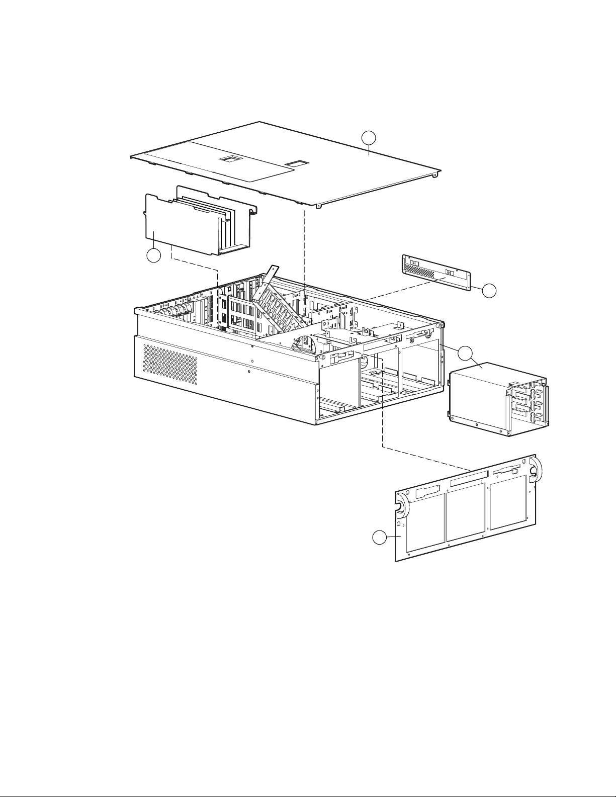
Mechanical Parts Exploded View
3
2
4b
4a
Figure 1-1. Exploded view of the Compaq ProLiant 6400R server mechanical parts
1
Page 13

Mechanical Spare Parts List
Ref Description Spares Part #
CHASSIS
1 Chassis with Ultra2 drive cage 176668-001
2 Top access panel 101922-001
3 PCI Hot Plug basket insulator 387886-001
MISCELLANEOUS
4 Miscellaneous hardware kit 122634-001
a) Front bezel
b) Side access panel
Illustrated Parts Catalog 1-3
Table 1-1
Mechanical Spare Parts List
Page 14
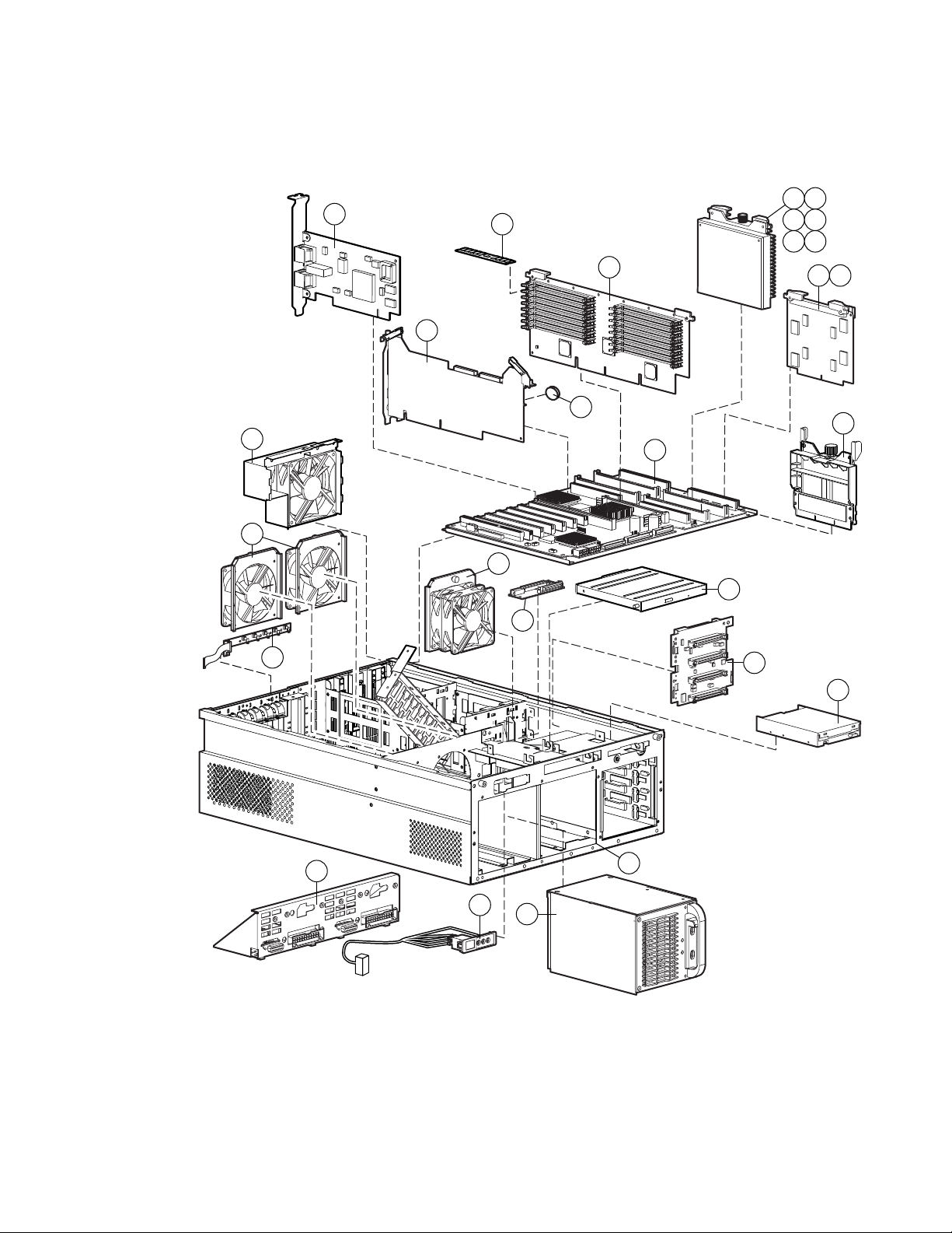
1-4 Compaq ProLiant 6400R Maintenance and Service Guide
System Components Exploded View
19
13
4
3
20
8a 9a
8b 9b
8c 9c
12
7
17
10a10b
11
18
15
2
23
16
14
24
1
6
5
Figure 1-2. Exploded view of the Compaq ProLiant 6400R server system components
Page 15

System Components Spare Parts List
System Components Spare Parts List
Ref Description Spares Part #
CHASSIS
1 Chassis 176668-001
ASSEMBLIES
2 Hot-plug dual redundant CPU fan #3 and #4 101931-001
3 Hot-plug I/O fan (2 per system) #1 and #2 101933-001
4 External rear hot-plug redundant system fan assemblies #5 and #6 158608-001
SYSTEM COMPONENTS
Power supply, 450 W, hot-plug 101920-001
5
6 Power switch and LED 101976-001
7 Replacement battery, peripheral board 179322-001
Illustrated Parts Catalog 1-5
Table 1-2
500-MHz/100 Xeon (512-K) processor with heat sink 116313-001
8a
500-MHz/100 Xeon (1-MB) processor with heat sink * 122636-001
8b
500-MHz/100 Xeon (2-MB) processor with heat sink * 122637-001
8c
9a 550-MHz/100 Xeon (512-K) processor with heat sink * 122635-001
9b 550-MHz/100 Xeon (1-MB) processor with heat sink * 122639-001
9c 550-MHz/100 Xeon (2-MB) processor with heat sink * 122640-001
10a Non-redundant Processor Power Module 328701-001
10b Redundant Processor Power Module * 328842-001
11 Processor terminator module 329271-001
* Not shown
continued
Page 16

1-6 Compaq ProLiant 6400R Maintenance and Service Guide
Table 1-2
System Components Spare Parts List
Ref Description Spares Part #
BOARDS
Memory board 328703-001
12
13 Peripheral board 328844-001
14 Ultra2 SCSI simplex board 387090-001
15 Power backplane board with tray 101973-001
16 CD-ROM drive adapter board 101927-001
17 System board and tray 123888-001
18 PCI Hot Plug switch/LED board and cable 328835-001
19 Dual Port PCI Netelligent 10/100 I-Base (NIC) 338478-001
MEMORY
64-MB dual inline memory module (buffered ECC, EDO 50 ns) 330739-001
20
128-MB dual inline memory module (buffered ECC, EDO 50 ns) * 330740-001
21
continued
256-MB dual inline memory module (buffered ECC, EDO 50 ns) * 330741-001
22
MEDIA STORAGE DEVICES
23 24X Max low-profile CD-ROM drive 128400-001
24 1.44-MB diskette drive 288456-001
* Not shown
continued
Page 17

Illustrated Parts Catalog 1-7
Table 1-2
System Components Spare Parts List
Ref Description Spares Part #
MISCELLANEOUS
25 Miscellaneous power cable kit * 101952-001
a) CD/LVD power cable assembly
b) 10-position power cable assembly
c) 12-position power cable assembly
d) Hard drive power cable assembly
e) Left cable fan assembly 1
f) Left cable fan assembly 2
g) Right cable fan assembly
h) Rear cable fan assembly
26 Miscellaneous signal cable kit * 101953-001
a) PCI cable assembly
b) Diskette drive cable assembly
continued
c) Miscellaneous signal cable assembly
d) CD-ROM drive signal cable assembly
e) LVD signal cable assembly
f) 26-pin power sensor cable assembly
g) PCI Hot Plug cable assembly
27 Diskette drive signal extension cable kit * 169038-001
28 Miscellaneous hardware kit * 122634-001
a) Front bezel (shown as item 4a in ”Mechanical Spare Parts List”)
b) Side access panel (shown as item 4b in ”Mechanical Spare Parts List”)
29 PCI slot cover * 271918-001
30a Return kit * 161500-001
30b Return kit ** 122645-001
31 Carton and buns (international) * 122645-002
32 Maintenance and service guide * 101978-001
33 Illustrated parts map * 101977-002
OPTIONS
34 Power supply blank cover * 122641-001
* Not shown
** For earlier 500-MHz models of the ProLiant 6400R server with a single rear CPU fan, instead of the external rear system
fan assembly
Page 18

Chapter 2
Removal and Replacement Procedures
This chapter provides subassembly and module-level removal and replacement procedures for
Compaq ProLiant 6400R servers, and unless otherwise specified, the procedures apply to
ProLiant 6400R servers containing 500- or 550-MHz processors. After completing all necessary
removal and replacement procedures, run the Diagnostics program to verify that all components
operate properly.
To service ProLiant 6400R servers, you might need the following:
■ Torx T-15 screwdriver
■ 4-mm flat-blade screwdriver
■ Phillips screwdriver
■ Wire cutters
■ From the Compaq SmartStart and Support Software CD:
G System Configuration Utility software
G Drive Array Advanced Diagnostics (DAAD) software
G Diagnostics software
Electrostatic Discharge Information
A discharge of static electricity can damage static-sensitive devices or microcircuitry. Proper
packaging and grounding techniques are necessary precautions to prevent damage. To prevent
electrostatic damage,
■ Transport products in static-safe containers, such as conductive tubes, bags, or boxes.
■ Keep electrostatic-sensitive parts in their containers until they arrive at static-free stations.
■ Cover workstations with approved static-dissipating material. Provide a wrist strap
connected to the work surface and properly grounded tools and equipment.
■ Keep the work area free of nonconductive materials, such as ordinary plastic assembly
aids and foam packing.
■ Always be properly grounded when touching a static-sensitive component or assembly.
■ Avoid touching pins, leads, or circuitry.
Page 19
2-2 Compaq ProLiant 6400R Maintenance and Service Guide
■ Always place drives, printed circuit boards (PCB) assembly-side down.
■ Use conductive field service tools.
Symbols on Equipment
These symbols may be located on equipment in areas where hazardous conditions may exist.
This symbol in conjunction with any of the following symbols indicates the presence of a
potential hazard. The potential for injury exists if warnings are not observed. Consult your
documentation for specific details.
This symbol indicates the presence of hazardous energy circuits or electric shock hazards.
Refer all servicing to qualified personnel.
WARNING: To reduce the risk of injury from electric shock hazards, do not open this
enclosure. Refer all maintenance, upgrades, and servicing to qualified personnel.
This symbol indicates the presence of electric shock hazards. The area contains no user or
field serviceable parts. Do not open for any reason.
WARNING: To reduce the risk of injury from electric shock hazards, do not open this
enclosure.
This symbol on an RJ-45 receptacle indicates a Network Interface Connection.
WARNING: To reduce the risk of electric shock, fire, or damage to the equipment, do not
plug telephone or telecommunications connectors into this receptacle.
This symbol indicates the presence of a hot surface or hot component. If this surface is
contacted, the potential for injury exists.
WARNING: To reduce the risk of injury from a hot component, allow the surface to cool
before touching.
These symbols on power supplies or systems indicate the equipment is supplied
by multiple sources of power.
WARNING: To reduce the risk of injury from electric shock, remove all power
cords to completely disconnect power from the system.
This symbol indicates that the component exceeds the recommended weight for one
individual to handle safely.
WARNING: To reduce the risk of personal injury or damage to the equipment, observe local
34 kg
occupational health and safety requirements and guidelines for manual material handling.
75 lb
Page 20
Preparation Procedures
Hot-Pluggable Components
Before the removal of any serviceable part, determine whether it is hot-pluggable or
non-hot-pluggable. If it is hot-pluggable, do not perform a power shutdown of the server. The
access panels can be removed while the server is turned on without system shutdown. When the
server is in Standby mode, portions of the power supply, auxiliary power (+5V), and some
internal circuitry remain active.
Non-Hot-Pluggable Components
If the part is non-hot-pluggable, shut down the server. Non-hot-pluggable parts include the
processor, Processor Power Module, system board, memory board, Dual Inline Memory
Modules (DIMMs), peripheral board, and modem. Refer to “Powering Down the Server” later
in this chapter for complete power-down instructions.
WARNING: To reduce the risk of injury from electric shock, remove all power
cords to completely disconnect power from the system.
Removal and Replacement Procedures 2-3
Powering Down the Server
System power in the ProLiant 6400R Server does not completely shut off with the front panel
Power On/Standby switch. The two positions of the switch function as On and Standby, rather
than On and Off. The Standby position removes power from most of the electronics and the
drives, but portions of the power supply and some internal circuitry remain active.
IMPORTANT: To completely remove all power from the system, you must disconnect the power cord
from the server. In systems with multiple power supplies, you must disconnect all the power cords to
completely remove power from the system.
IMPORTANT: It is not necessary to turn off the server to replace hot-plug devices such as power
supplies, fans, or PCI Hot Plug boards.
Before beginning any of the removal and replacement procedures for non-hot-plug devices,
1. Move the Power On/Standby switch to the Standby position.
2. Disconnect the AC power cord from the AC outlet and then from the server.
3. Disconnect all external peripheral devices from the server.
For some removal and replacement procedures, you must remove the server from the rack and
place it on a sturdy table or workbench. Refer to the ProLiant 6400R Setup and Installation
Guide for instructions.
Page 21
2-4 Compaq ProLiant 6400R Maintenance and Service Guide
WARNING: Because the rack allows stacking of computer components on a vertical rather
than horizontal plane, ensure that precautions have been taken to provide for rack stability and
safety. It is important to follow these precautions to provide rack stability and safety and to
protect both personnel and property. Heed all cautions and warnings throughout the installation
instructions that came with the server.
WARNING: To reduce the risk of personal injury, always ensure that the rack is adequately
stabilized before extending a component outside the rack. A rack may become unstable if more
than one component is extended for any reason. Extend only one component at a time.
WARNING: To reduce the risk of personal injury or damage to the equipment, be sure that:
■ The leveling jacks are extended to the floor.
■ The full weight of the rack rests on the leveling jacks.
■ The stabilizers are attached to the rack if it is a single rack installation.
■ The racks are coupled together in multiple rack installations.
CAUTION: Electrostatic discharge can damage electronic components. Ensure proper
grounding before beginning any installation procedure. For more information, refer to the
“Electrostatic Discharge” section earlier in this chapter.
Server Warnings and Precautions
WARNING: To reduce the risk of personal injury from hot surfaces, allow the internal system
components to cool before touching.
WARNING: To reduce the risk of electric shock or damage to the equipment,
■ Do not disable the power cord grounding plug. The grounding plug is an important safety
feature.
■ Plug the power cord into a grounded (earthed) electrical outlet that is easily accessible at
all times.
■ Disconnect power from the server by unplugging the power cord from either the electrical
outlet or the server.
This symbol indicates that the component exceeds the recommended weight for one
individual to handle safely.
WARNING: To reduce the risk of personal injury or damage to the equipment, observe local
34 kg
occupational health and safety requirements and guidelines for manual material handling.
75 lb
CAUTION: Protect the server from power fluctuations and temporary interruptions with a
regulating uninterruptible power supply (UPS). This device protects the hardware from damage
caused by power surges and voltage spikes and keeps the system in operation during a power
failure.
CAUTION: The ProLiant 6400R server must always be operated with the system unit cover on.
Proper cooling will not be achieved if the system unit cover is removed.
Page 22
Top Access Panel
The standard shipment of a ProLiant 6400R server is in a standard in a rack-mount
configuration. Remove the top access panel to service the internal components.
WARNING: To reduce the risk of personal injury from hot surfaces, allow the internal system
components to cool before touching them.
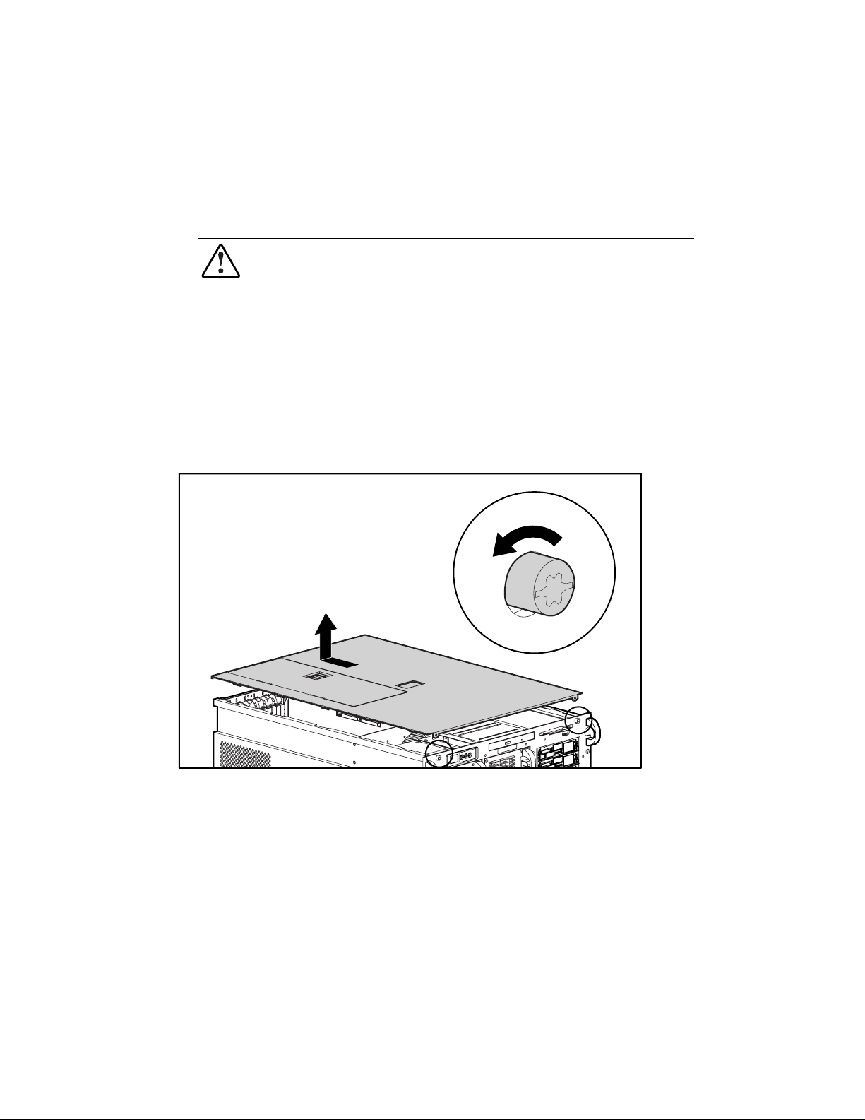
To remove the top access panel,
1. Perform the preparation procedures. See “Preparation Procedures” earlier in this chapter.
2. Using a Torx T-15 screwdriver, loosen the two captive screws securing the top access
panel to the bezel.
3. Slide the top access panel back, and then lift it from the chassis.
NOTE: The PCI Hot Plug access door allows you to access the PCI Hot Plug area without removing the
top access panel.
Removal and Replacement Procedures 2-5
Figure 2-1. Removing the top access panel
Reverse steps 1 through 3 to replace the top access panel.
Page 23
2-6 Compaq ProLiant 6400R Maintenance and Service Guide
Power On/Standby Switch
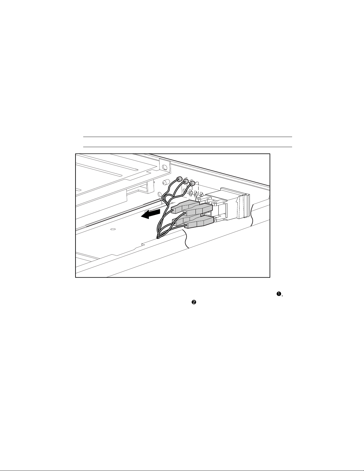
To remove the Power On/Standby switch and cable assembly,
1. Perform the preparation procedures. See “Preparation Procedures” earlier in this chapter.
2. Remove the top access panel. See “Top Access Panel” earlier in this chapter.
3. Disconnect the power switch cables from the power switch.
4. Disconnect the clips connected to each of the LEDs.
IMPORTANT: Label each wire before disconnection from the LED terminals.
Figure 2-2. Disconnecting the Power On/Standby switch
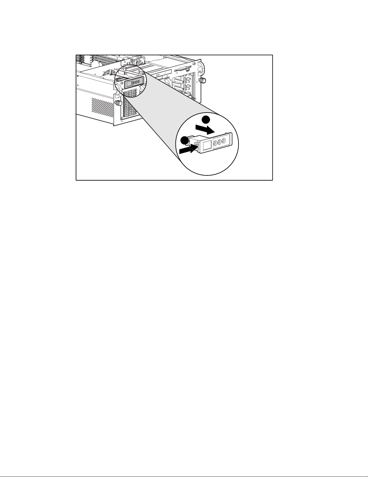
5. Using a 4-mm flat-blade screwdriver, press in the tabs on each side of the switch
then pull the switch out the front of the bezel
.
, and
Page 24
Removal and Replacement Procedures 2-7
2
1
Figure 2-3. Removing the Power On/Standby switch
Reverse steps 1 through 5 to replace the Power On/Standby switch.
Page 25
2-8 Compaq ProLiant 6400R Maintenance and Service Guide
Front Bezel
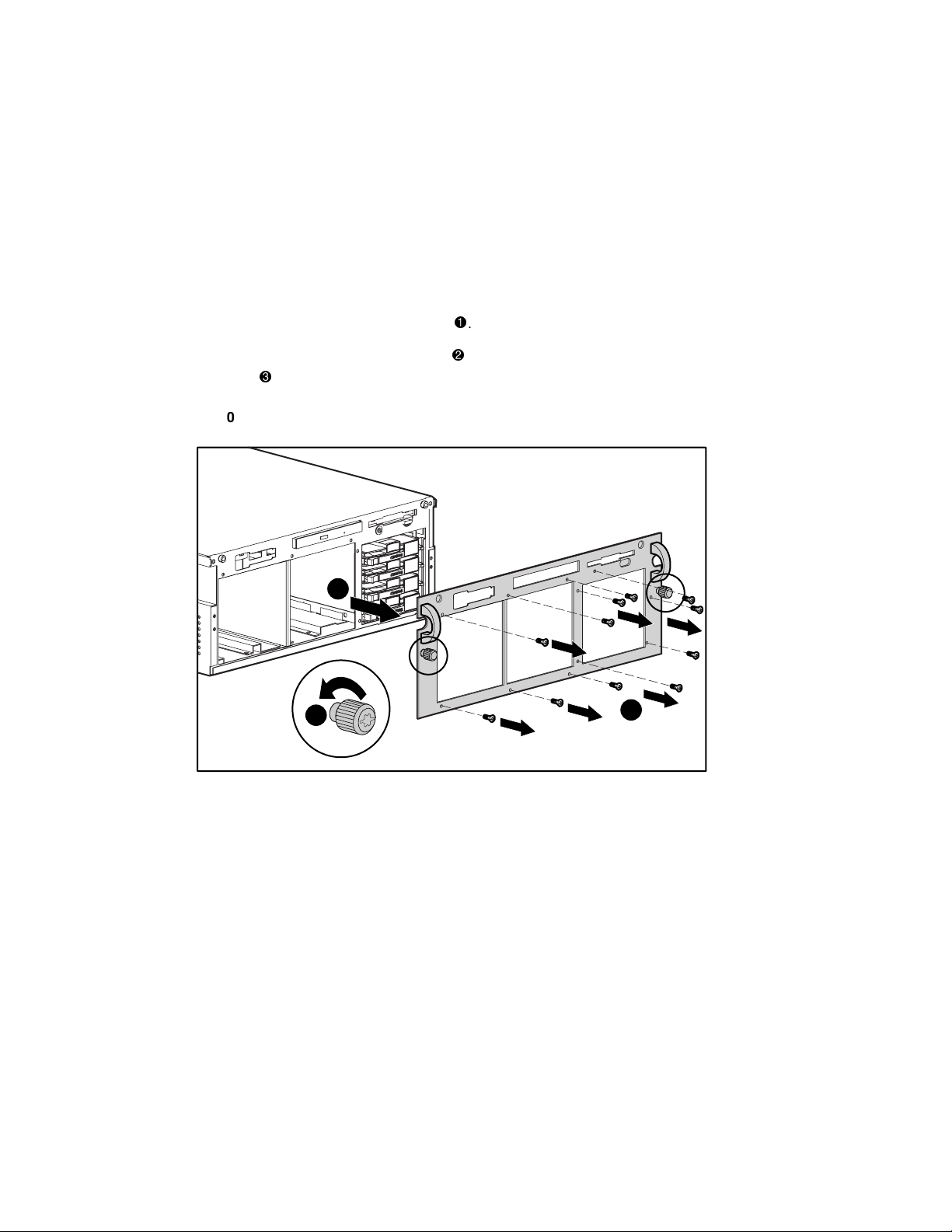
To remove the front bezel,
1. Perform the preparation procedures. See “Preparation Procedures” earlier in this chapter.
2. Remove the Power On/Standby switch. See “Power On/Standby Switch” earlier in the
chapter.
3. Remove the eleven Torx T-15 screws
4. Loosen the two captive thumbscrews
server
NOTE: This step is required only if the front bezel is removed while the unit is in the rack.
.
3
2
.
, and then pull the front bezel away from the
1
Figure 2-4. Removing the front bezel
Reverse steps 1 through 4 to replace the front bezel.
Page 26
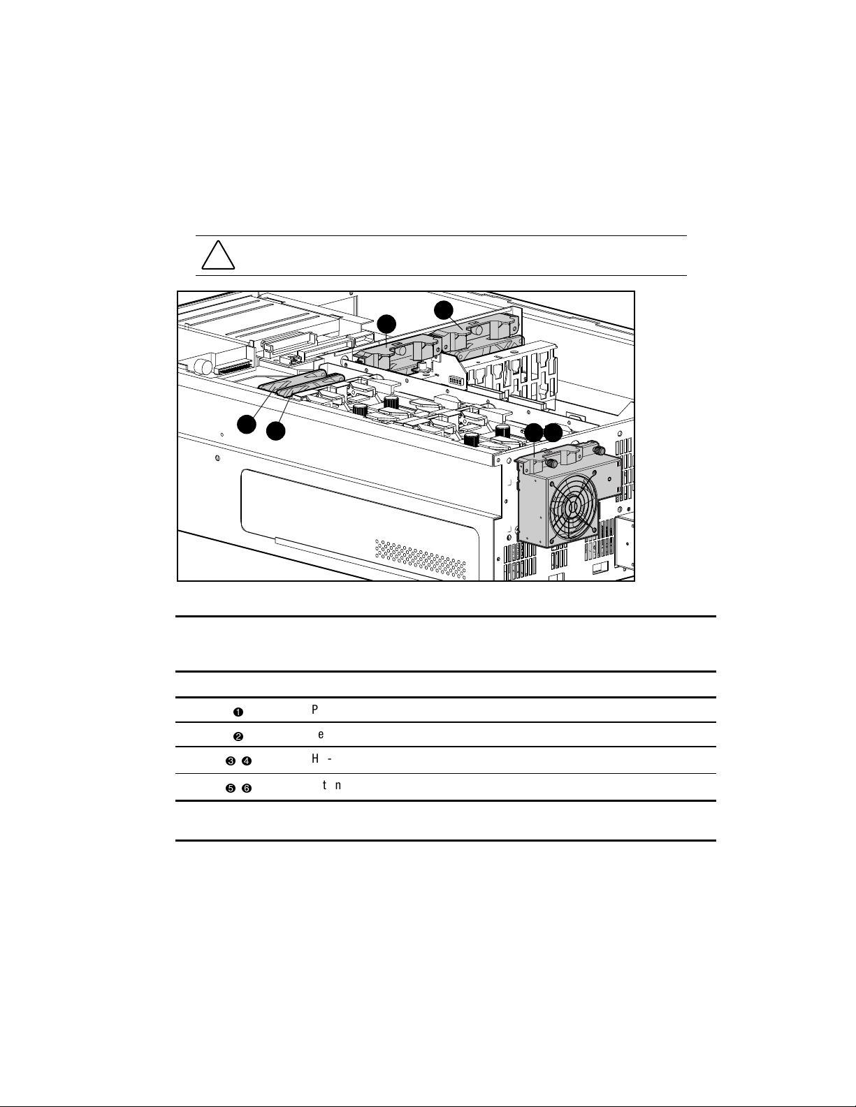
Hot-Plug Fans
ProLiant 6400R servers ship with six, redundant hot-plug fans. All of the fans are redundant.
Figure 2-5 and Table 2-1 show the hot-plug fan locations and their descriptions.
Removal and Replacement Procedures 2-9
CAUTION: Leave failed or failing fans connected to the system until they can be replaced.
4
3
Figure 2-5. Hot-plug fan locations
Fan Description
,
Primary I/O hot-plug fan
Secondary I/O hot-plug fan
Hot-plug dual redundant CPU fan assembly
2
1
5 6
Table 2-1
Hot-Plug Fan Locations
,
Note: An amber LED fan indicator indicates the fan has failed. If the LED indicator is green, then the fan is
working properly. See the section “Hot-Plug Fan LED Indicators” in Chapter 4.
External rear hot-plug redundant system fan assembly
Page 27
2-10 Compaq ProLiant 6400R Maintenance and Service Guide
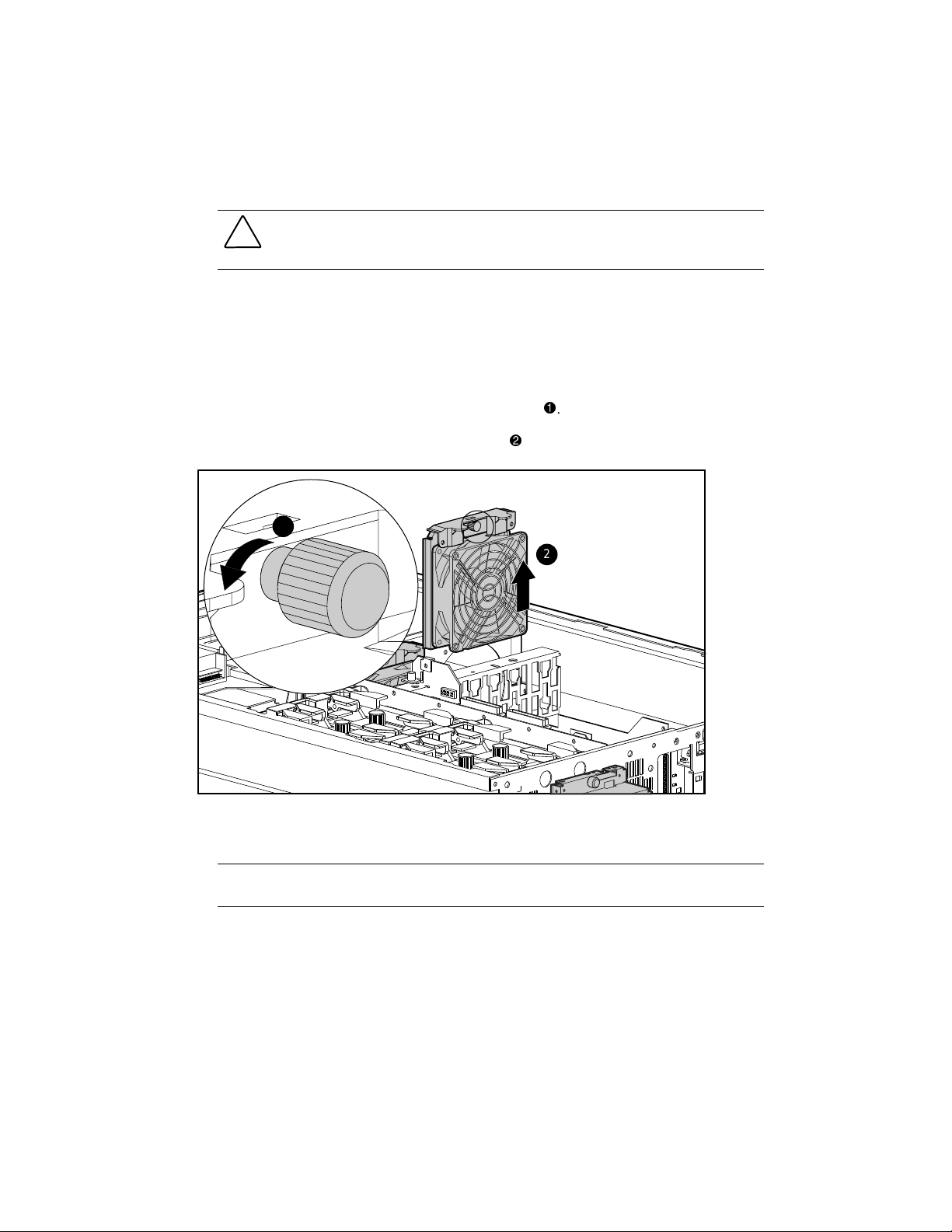
I/O Hot-Plug Fans
CAUTION: If you must remove a fan while the server is powered up, you have 5 minutes to
change it before server shutdown (Windows NT, UNIX, and Novell NetWare). Removal of both
fans will cause overheating and subsequent server shutdown.
NOTE: An amber LED fan indicator indicates the fan has failed. If the LED indicator is green, the fan is
working properly. See the section “Hot-Plug Fan LED Indicators” in Chapter 4.
To remove an I/O hot-plug fan:
1. Remove the top access panel. See “Top Access Panel” earlier in this chapter.
2. Loosen the thumbscrew located at the top of the fan
3. Lift the hot-plug fan straight out of the chassis
1
Figure 2-6. Removing an I/O hot-plug fan
.
Reverse steps 1 through 3 to replace an I/O hot-plug fan.
2
.
IMPORTANT: It is not necessary to turn off the server to replace hot-plug devices, such as power
supplies, fans, or PCI Hot Plug boards.
Page 28
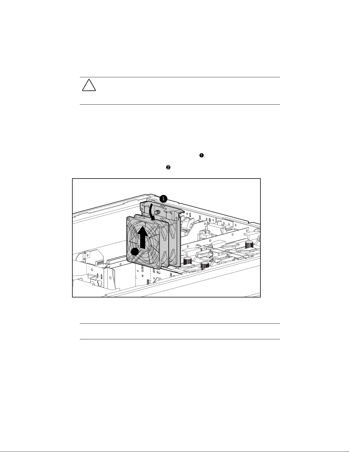
Hot-Plug Dual Redundant CPU Fan Assembly
CAUTION: If you must remove the hot-plug dual redundant CPU fan assembly while the server
is powered up, you have 5 minutes to change it before shutdown (Windows NT, UNIX, and
Novell NetWare). Removal of both fans will cause overheating and subsequent server
shutdown.
NOTE: An amber LED fan indicator indicates the fan has failed. If the LED indicator is green, the fan is
working properly. See the section “Hot-Plug Fan LED Indicators” in Chapter 4.
To remove the hot-plug, dual-redundant CPU fan assembly,
1. Remove the top access panel. See “Top Access Panel” earlier in this chapter.
Removal and Replacement Procedures 2-11
2. Loosen the thumbscrew located at the top of the fan
3. Lift the fan straight out of the chassis
2
Figure 2-7. Removing the hot-plug, dual-redundant CPU fan assembly
.
1
.
Reverse steps 1 through 3 to replace the hot-plug, dual-redundant CPU fan assembly.
IMPORTANT: It is not necessary to turn off the server to replace hot-plug devices, such as power
supplies, fans, or PCI Hot Plug boards.
Page 29
2-12 Compaq ProLiant 6400R Maintenance and Service Guide
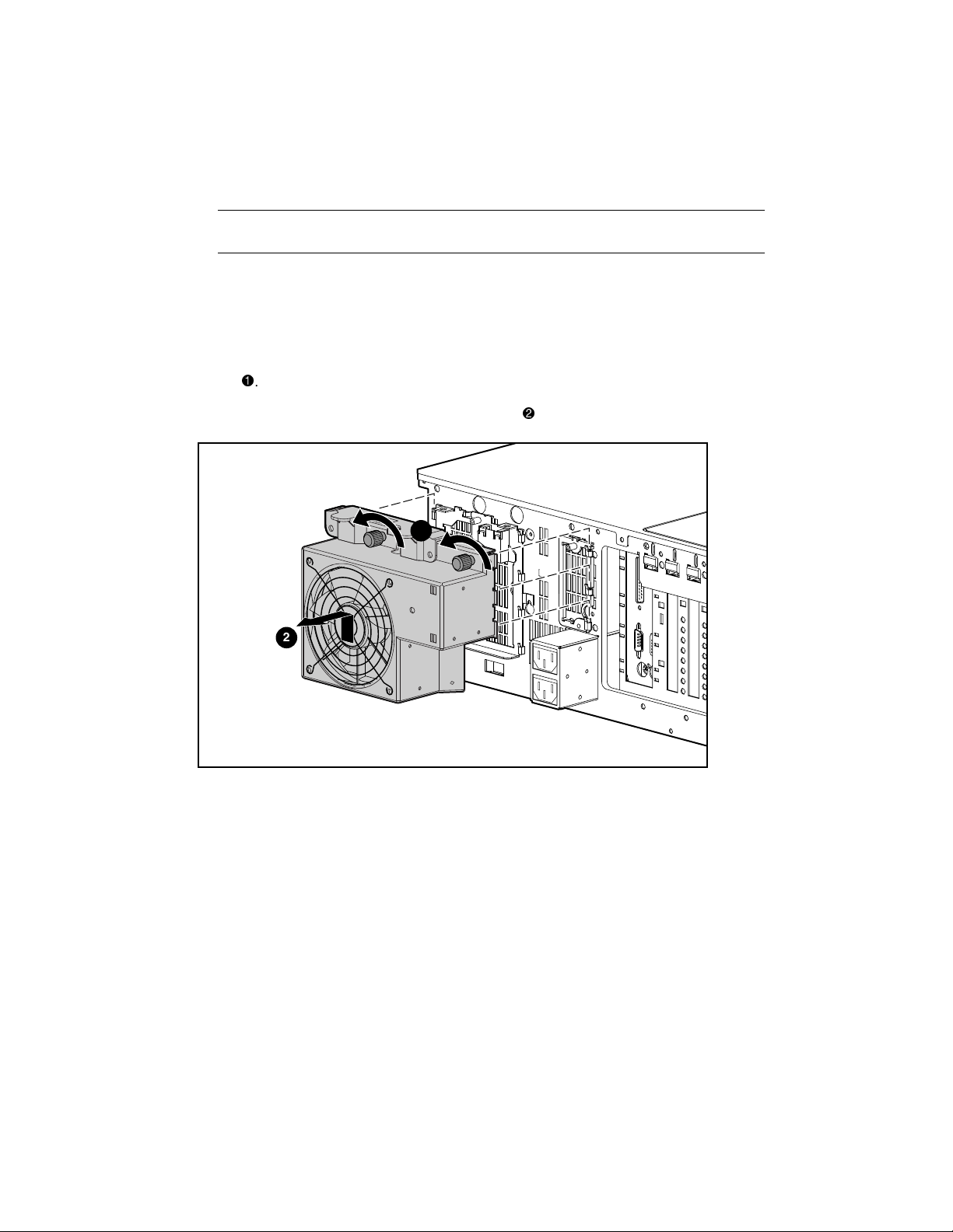
External Rear Hot-Plug Redundant System Fan Assembly
IMPORTANT: It is not necessary to turn off the server to replace hot-plug devices such as power
supplies, fans, or PCI Hot Plug boards.
NOTE: If the fan LED indicator is amber, the fan has failed. If the LED indicator is green, the fan is
working properly. See the section “Hot-Plug Fan LED Indicators” in Chapter 4.
To remove an external rear hot-plug redundant CPU fan,
1. From the back of the server, loosen the captive thumbscrew located at the top of the
.
fan
2. Move the fan up and then away from the chassis
1
2
2
Figure 2-8. Removing the external rear hot-plug redundant system fan assembly
Reverse steps 1 and 2 to replace the external rear hot-plug redundant CPU fan.
.
Removable Media and Hard Drives
Media and hard drives are removed for replacement, upgrades, or during the removal of the
Ultra2 SCSI simplex board.
Page 30
Media Storage
ProLiant 6400R Servers can be configured with four Ultra2 1-inch hot-plug hard drives. Drives
can be of any storage capacity but must be mounted on Compaq hot-plug drive trays. Other
standard devices include
■ Preinstalled 3.5-inch 1.44-MB diskette drive
■ Preinstalled 24X or higher low-profile CD-ROM drive
Removal and Replacement Procedures 2-13
3 1
3
2
1
0
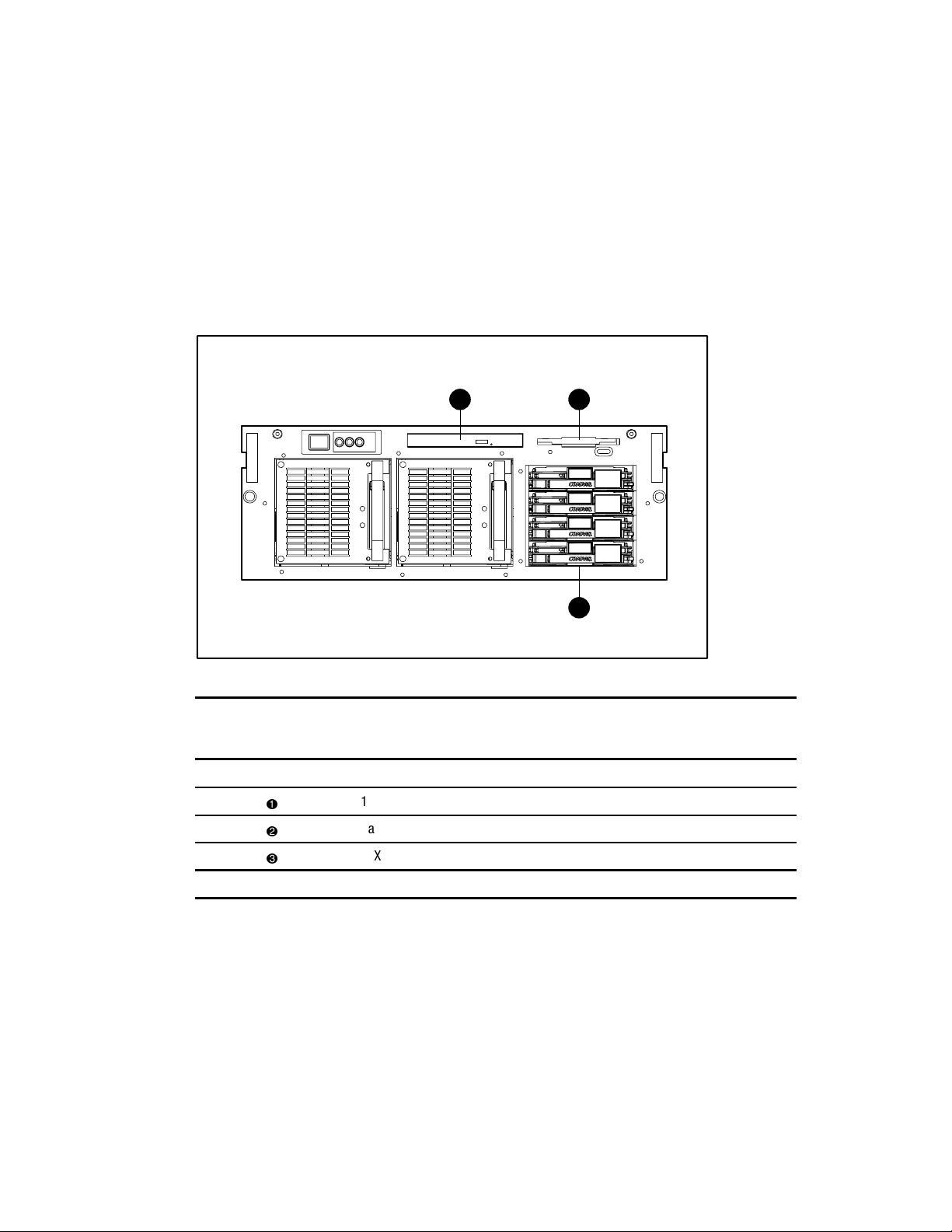
Figure 2-9. Removable media and hard drive locations
Table 2-2
Drive Locations
Item Description
SCSI drive IDs are shown
1.44-MB standard diskette drive
Bay for four 1-inch drives *
24X or higher low-profile CD-ROM drive
2
Page 31

2-14 Compaq ProLiant 6400R Maintenance and Service Guide
Hot-Plug Hard Drives
CAUTION: Never turn a ProLiant 6400R storage system off while the server controlling it is
powered on. Doing so will cause the SMART Controller in the server to turn on the amber Drive
Failure LED icon. This could result in permanent data loss.
When removing and replacing hot-plug hard drives,
■ Never remove a hot-plug hard drive if the LED icon is green. See “Hot-Plug Hard Drives”
in Chapter 4. Replace a hot-plug hard drive only when the LED icon is amber.
■ Never remove more than one hard drive at a time. If the server is set in an array
configuration and a hard drive is replaced, the controller uses data from the other drives in
the array to reconstruct data on the replacement drive. If more than one hard drive is
removed, a complete data set is not available to reconstruct data on the replacement
drives.
■ Never remove a working hard drive when another one has been marked as failed by the
controller. Permanent data loss will occur. Hard drives marked as failed by the controller
are indicated by the amber Drive Failure LED icon on the drive tray.
■ Never remove a drive while another is being rebuilt. A drive Online LED icon flashes
green while it is being rebuilt. A replaced drive is restored from data stored on the other
drives.
■ If only one hard drive is used, install it in the lowest numbered bay. See “Media Storage”
under “Removable Media and Hard Drives” in this chapter. If several drives are used, the
system boot drive should be installed in the lowest numbered bay.
CAUTION: Replace a hot-plug hard drive only when the drive LED icon is amber. Do not
remove a hot-plug hard drive if the online LED icon is green.
Page 32

To remove a hot-plug hard drive,
Removal and Replacement Procedures 2-15
1. Press in on the port-colored release tab
2. Open the locking release lever
3. Pull the hard drive from the drive cage
3
Figure 2-10. Removing a hot-plug hard drive
.
that secures the hard drive in the drive bay.
.
1
2
2
Reverse steps 1 through 3 to replace a hot-plug hard drive.
Page 33

2-16 Compaq ProLiant 6400R Maintenance and Service Guide
Ultra2 SCSI Simplex Board
To remove the Ultra2 SCSI simplex board,
1. Perform the preparation procedures. See “Preparation Procedures” earlier in this chapter.
2. Disconnect the SCSI and power cables from the simplex board
.
3. Remove any hard drives. See “Hot-Plug Hard Drives” under the section “Removable
Media and Hard Drives” earlier in this chapter.
4. Remove the dual fan assembly. See “External Rear Hot-Plug Redundant System Fan
Assembly” earlier in this chapter.
5. Remove the thumbscrew securing the simplex board to the hard drive cage
6. Move the simplex board up, back, and then out of the chassis
2
3
.
.
1
Figure 2-11. Removing the Ultra2 SCSI simplex board
Reverse steps 1 through 6 to replace an Ultra2 SCSI simplex board.
Page 34

Removable Media Assembly
The removable media assembly holds two removable media devices, including a 24X or higher
low-profile CD-ROM drive and a 1.44-MB diskette drive.
To remove the removable media assembly,
1. Perform the preparation procedures. See “Preparation Procedures” earlier in this chapter.
2. Remove the top access panel. See “Top Access Panel” earlier in this chapter.
3. Disconnect all cables from the CD-ROM and diskette drives.
Removal and Replacement Procedures 2-17
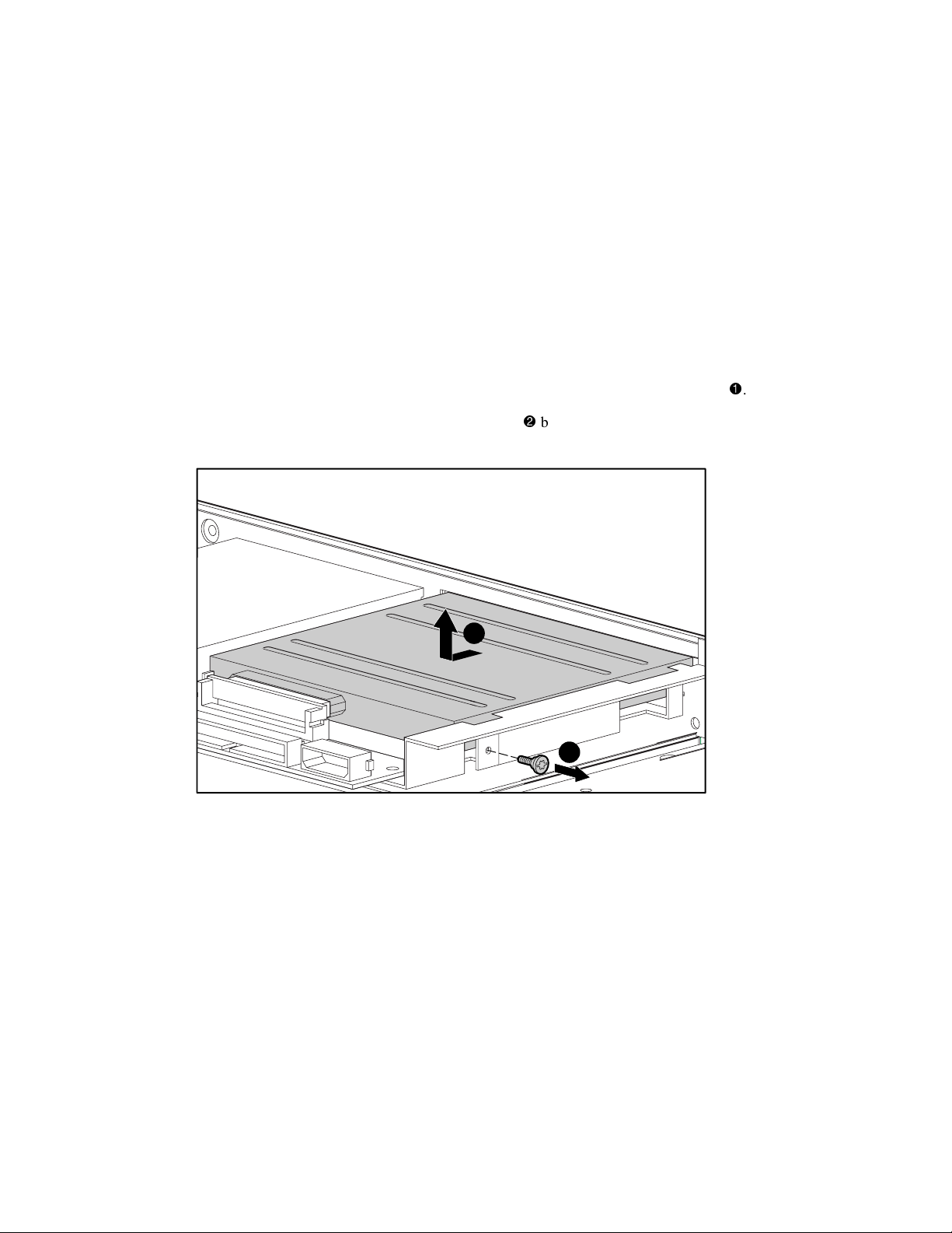
4. Loosen the captive thumbscrew securing the removable media assembly to the chassis
5. Lift the removable media assembly from the server
.
6. Remove the 1.44-MB diskette drive. See “1.44-MB Diskette Drive” later in this chapter.
7. Remove the 24X or higher low-profile CD-ROM drive. See “24X or Higher Low-Profile
CD-ROM Drive Adapter Board” later in this chapter.
1
2
.
Figure 2-12. Removing the removable media assembly
Reverse steps 1 through 7 to replace the removable media assembly.
IMPORTANT: When the removable media assembly is removed, the diskette drive and the 24X or higher
low-profile CD-ROM drive can be easily removed. See “1.44-MB Diskette Drive” “24X or Higher
Low-Profile CD-ROM Drive Adapter Board” later in this chapter.
Page 35

2-18 Compaq ProLiant 6400R Maintenance and Service Guide
1.44-MB Diskette Drive
ProLiant 6400R Servers ship with a standard 1.44-MB diskette drive. The drive may be
removed in one of two ways, with the removable media assembly still secured to the server or
by removal of the removable media assembly. See “Removable Media Assembly” earlier in this
chapter.
To remove the diskette drive,
1. Perform the preparation procedures. See “Preparation Procedures” earlier in this chapter.
2. Disconnect all cables from the diskette drive if you have not already done so
3. Loosen the thumbscrew securing the drive to the drive tray
4. Move the diskette drive back and then up from the drive tray
3
2
Figure 2-13. Removing the diskette drive
.
.
1
.
Reverse steps 1 through 4 to replace the diskette drive.
Page 36

24X or Higher Low-Profile CD-ROM Drive Adapter Board
The 24X or higher low-profile CD-ROM drive adapter board may be removed with the
removable media assembly still secured to the server or by removal of the removable media
assembly. See “Removable Media Assembly” earlier in this chapter.
To remove the 24X or higher low-profile CD-ROM drive adapter board,
1. Perform the preparation procedures. See “Preparation Procedures” earlier in this chapter.
2. Remove the removable media assembly. See “Removable Media Assembly” earlier in this
chapter.
Removal and Replacement Procedures 2-19
3. Disconnect the IDE and power cables from the adapter board
if you have not already
done so.
4. Remove the two thumbscrews
securing the adapter board to the removable media
assembly.
5. Unplug the CD-ROM drive adapter board from the back of the 24X or higher low-profile
CD-ROM drive
2
1
.
3
Figure 2-14. Removing the 24X or higher low-profile CD-ROM drive adapter board
NOTE: The CD-ROM drive has been removed from the removable media assembly for clarity.
Reverse steps 1 through 5 to replace the 24X or higher low-profile CD-ROM drive adapter
board.
Page 37
2-20 Compaq ProLiant 6400R Maintenance and Service Guide
24X or Higher Low-Profile CD-ROM Drive
ProLiant 6400R Servers ship with a 24X or higher low-profile CD-ROM drive. The drive may
be removed with the removable media assembly still secured to the server or by removal of the
removable media assembly. See “Removable Media Assembly” earlier in this chapter.
To remove the 24X or higher low-profile CD-ROM drive,
1. Perform the preparation procedures. See “Preparation Procedures” earlier in this chapter.
2. Remove the CD-ROM drive adapter board screws. See “24X or Higher Low-Profile
CD-ROM Drive Adapter Board” earlier in this chapter.
3. Remove the screw securing the CD-ROM drive to the removable media assembly
4. Move the CD-ROM and adapter board assembly
back and then out of the removable
media assembly.
2
1
Figure 2-15. Removing the CD-ROM drive
.
Page 38

Removal and Replacement Procedures 2-21
5. Unplug the CD-ROM drive from the adapter board
Figure 2-16. Removing the CD-ROM drive from the adapter board
Reverse steps 1 through 5 to replace the 24X or higher low-profile CD-ROM drive.
.
3
Cable Folding and Routing Diagrams
Figure 2-17 through Figure 2-21 show the recommended cabling layout for the 24X or higher
low-profile CD-ROM drive, 1.44-MB diskette drive, external fan, and power supply. These
figures can be used when replacing and reconnecting internal components.
24X or Higher Low-Profile CD-ROM Cable
Figure 2-17. Folding and routing diagram of the 24X or higher low-profile CD-ROM drive cable
Page 39

2-22 Compaq ProLiant 6400R Maintenance and Service Guide
Diskette Drive Cable
Figure 2-18. Folding and routing diagram of the diskette drive cable with the diskette drive signal
extension cable
External Fan Cable
Figure 2-19. Folding and routing diagram of the external fan cable
NOTE: The fan cable folding and routing diagram is identical for the external rear hot-plug redundant
CPU fan or the external rear hot-plug redundant system fan assembly.
Page 40

Power Supply Cable
Figure 2-20. Folding and routing diagram of the power supply cable
Removal and Replacement Procedures 2-23
Page 41

2-24 Compaq ProLiant 6400R Maintenance and Service Guide
Power Supply Signal Cable
2
1
2
1
3
Figure 2-21. Power supply signal cables
Item Description
10-position cable
12-position cable
Miscellaneous cable
Table 2-3
Power Supply Cables
Page 42

Hot-Plug Power Supply
WARNING: To reduce the risk of electric shock or damage to the equipment,
■ Unplug the power cord before removing the power supply from the server.
■ Install the power supply before connecting the power cord to the power supply.
CAUTION: If one of the power supplies is removed, it must either be replaced by another
power supply, or a blank bezel should be inserted immediately to allow proper airflow. Do not
operate for more than a few minutes without taking these precautions.
NOTE: It is not necessary to place the system in Standby for a hot-plug power supply replacement in a
redundant power supply configuration.
To remove a hot-plug power supply,
1. Unplug the AC power cord from the hot-plug power supply.
Removal and Replacement Procedures 2-25
2. Grasp the power supply handle, and slide the release lever upward
3. Pull the power supply from the server
.
B
A
2
Figure 2-22. Removing a hot-plug power supply
Reverse steps 1 through 3 to replace a hot-plug power supply.
.
1
Page 43

2-26 Compaq ProLiant 6400R Maintenance and Service Guide
Processors, Processor Terminator Modules, and
Processor Power Modules
ProLiant 6400R servers contain at least one processor, one Processor Power Module (PPM), and
three processor terminator modules. ProLiant 6400R servers can support a maximum of four
processors and corresponding PPMs.
IMPORTANT: Processor Power Modules must always be installed in the slots next to each installed
processor. Each processor slot must be populated by a processor or a terminator module for proper bus
termination.
IMPORTANT: The processor is keyed to ensure correct alignment.
Processor and Related Component Locations
8 7 5
4 3 1
Figure 2-23. Location of processor and related components
6
2
Table 2-4
Processor and Related Component Locations
Item Description Item Description
Processor 1
Processor Power Module 1
Processor 2 or terminator module 2
Processor Power Module 2
Processor 3 or terminator module 3
Processor Power Module 3
Processor 4 or terminator module 4
Processor Power Module 4
Page 44

Processor
Removal and Replacement Procedures 2-27
IMPORTANT: When installing a server with Pentium III Xeon processors running at speeds equal to or
greater than 550 MHz in Compaq Rack 7000 series racks [part numbers 165753-001 (42U) and
163747-001 (22U)], the new processor technology requires the installation of a new Compaq High
Airflow Rack Door Insert [part number 327281-B21 (single) or 327281-B22 (six-pack) for 42U racks and
157847-B21 (single) or 157847-B22 (six-pack) for 22U racks.
NOTE: This notice applies to servers with Pentium III Xeon processors running equal to or greater than
550 MHz that will be installed in 7000 series racks. Compaq servers based on other processor
technologies, including Pentium III, do not require any rack changes.
To remove a processor,
1. Perform the preparation procedures. See “Preparation Procedures” earlier in this chapter.
2. Remove the top access panel. See “Top Access Panel” earlier in this chapter.
3. Loosen the retention screw
4. Pull up the ejector levers
.
.
5. Lift the processor out of the processor socket
2
Figure 2-24. Removing a processor
.
2
1
3
Reverse steps 1 through 5 to replace a processor.
Page 45

2-28 Compaq ProLiant 6400R Maintenance and Service Guide
Processor Power Module
ProLiant 6400R Servers support both PPMs and redundant PPMs (RPPMs). The PPM is
removed for access to the system board, for replacement, or for upgrade.
To remove the PPM from the system board,
1. Perform the preparation procedures. See “Preparation Procedures” earlier in this chapter.
2. Pull the ejector levers outward
3. Lift the PPM out of the socket
NOTE: This procedure can be followed for both PPMs and RPPMs.
1
Figure 2-25. Removing a PPM
.
.
1
2
Reverse steps 1 through 3 to replace a PPM.
Page 46

Processor Terminator Module
IMPORTANT: If you remove a processor, the processor terminator module must be reinstalled before
powering up the server. Failure to have either a processor or processor terminator module installed
results in an interlock fault condition that prevents the server from powering up.
To remove a processor terminator module,
1. Perform the preparation procedures. See “Preparation Procedures” earlier in this chapter.
2. Remove the top access panel. See “Top Access Panel” earlier in this chapter.
Removal and Replacement Procedures 2-29
3. Loosen the retention screw
.
4. Pull up the two ejector levers securing the processor terminator module in the
connector slot
5. Lift the processor terminator module out of the slot
Figure 2-26. Removing the processor terminator module
.
.
2
1
2
3
Reverse steps 1 through 5 to replace the processor terminator module.
Page 47

2-30 Compaq ProLiant 6400R Maintenance and Service Guide
Peripheral Board
The peripheral board is removed for access the system board or for replacement. See
“PCI Hot Plug Expansion Boards” for the slot location later in this chapter.
To remove the peripheral board,
1. Perform the preparation procedures. See “Preparation Procedures” earlier in this chapter.
2. Remove the top access panel. See “Top Access Panel” earlier in this chapter.
CAUTION: Disconnect all the power cords to completely remove power from the system. You
must disconnect the power cord from the server before removing the peripheral board.
3. Disconnect all cables from the peripheral board.
4. Loosen the two thumbscrews holding the board in place
5. Rotate the release levers outward
CAUTION: Rotating the peripheral board release levers a full 90 degrees will break the levers.
6. Lift out the peripheral board
1
.
.
2
2
3
.
Figure 2-27. Removing the peripheral board
Reverse steps 1 through 6 to replace the peripheral board.
Page 48

Memory
Removal and Replacement Procedures 2-31
The standard shipment of ProLiant 6400R servers have either 256 K or 1 GB of memory (four
64-MB or 256-MB DIMMs in bank 1). Memory is expandable to 4-GB (16x256-MB DIMMs).
Four memory banks of four DIMMs are supported. ProLiant 6400R Servers support 60 ns or
faster (ships with 50 ns), and 32-, 64-, 128-, or 256-MB error checking and correcting, EDO or
4-K or 8-K refreshed DIMMs.
DIMM 3
DIMM 4
DIMM 7
DIMM 8
DIMM 11
Bank 1
Bank 2
Bank 3
Bank 4
DIMM 12
DIMM 15
DIMM 16
Figure 2-28. Memory banks on the memory board
CAUTION: Use only Compaq approved DIMMs. DIMMs from other sources may adversely affect
data integrity. Power-On Self-Test (POST) will warn of nonsupported DIMMs.
The recommended DIMM replacement order is:
■ Bank 1 - DIMM 1, DIMM 2, DIMM 3, DIMM 4
■ Bank 2 - DIMM 5, DIMM 6, DIMM 7, DIMM 8
■ Bank 3 - DIMM 9, DIMM 10, DIMM 11, DIMM 12
DIMM 1
DIMM 2
DIMM 5
DIMM 6
DIMM 9
DIMM 10
DIMM 13
DIMM 14
■ Bank 4 - DIMM 13, DIMM 14, DIMM 15, DIMM 16
The following guidelines must be followed when replacing memory:
■ Supports 60 ns or faster and 32-, 64-, 128-, or 256-megabyte, ECC, EDO, or 4-K or 8-K
refreshed DIMMs.
NOTE: This server does not support Fast Page DIMMs.
■ DIMMs must be installed or removed one bank (four identical DIMMs) at a time. The size
and speed of each DIMM of a given bank must be identical.
Table 2-5 shows some of the possible memory upgrade configurations for ProLiant 6400R
servers.
Page 49

2-32 Compaq ProLiant 6400R Maintenance and Service Guide
Table 2-5
Examples of Memory Upgrade Combinations
Total Memory Bank 1 Bank 2 Bank 3 Bank 4
256 MB 4x64 MB
512 MB 4x64 MB 4x64 MB
768 MB 4x64 MB 4x64 MB 4x64 MB
1.024 GB 4x64 MB 4x64 MB 4x64 MB 4x64 MB
1.024 GB 4x256 MB
1.536 GB 4x128 MB 4x128 MB 4x128 MB
2.048 GB 4x128 MB 4x128 MB 4x128 MB 4x128 MB
3.072 GB 4x256 MB 4x256 MB 4x256 MB
4.096 GB 4x256 MB 4x256 MB 4x256 MB 4x256 MB
Address Bit Permuting
ProLiant 6400R servers offer enhanced memory performance depending on memory
configurations.
NOTE: All banks must contain four ECC, EDO DIMMs of the same size, speed, and manufacturer.
Address Bit Permuting (ABP) is an option that distributes memory addresses across two or four
banks of memory. Therefore, an ABP group may be two or four banks in size. The following are
memory configuration rules that permit ABP,
■ Two or four banks on a memory expansion board must be populated.
■ All banks within an ABP group (two banks for a two-bank group and four banks for a
four-bank group) must be of the same memory capacity.
■ The memory in the expansion board must be populated starting with bank 1, and each
populated bank must be adjacent.
For example, installing four 256-MB DIMMs in Bank 1 would achieve 1 GB of total memory
but would not enable ABP. However, installing 16 64-MB DIMMs, using all four banks, would
enable ABP and enhance memory performance.
Page 50

Memory Board
The memory board is removed for replacement, for access to the system board, or for DIMM
installations.
To remove the memory board:
1. Perform the preparation procedures. See “Preparation Procedures” earlier in this chapter.
2. Remove the top access panel. See “Top Access Panel” earlier in this chapter.
Removal and Replacement Procedures 2-33
3. Lift up the ejector levers on each side of the memory board
4. Lift the memory board from the slot
1
Figure 2-29. Removing the memory board
.
2
Reverse steps 1 through 4 to replace the memory board.
1
.
Page 51

2-34 Compaq ProLiant 6400R Maintenance and Service Guide
Dual Inline Memory Modules
DIMMs are removed for replacement, for replacement of the memory expansion board, or for
upgrading memory.
CAUTION: Use only Compaq DIMMs. DIMMs from other sources may adversely affect data
integrity. The Power-On Self-Test (POST) will warn of nonsupported DIMMs.
To remove a DIMM,
1. Perform the preparation procedures. See “Preparation Procedures” earlier in this chapter.
2. Remove the memory board. See “Memory Board” earlier in this chapter.
3. Pull out the ejector levers at each end of the memory module
4. Lift the module from the memory board
1
2
Figure 2-30. Removing a DIMM
.
.
1
Reverse steps 1 through 4 to replace the memory module. Align the key slot on the bottom edge
of each DIMM with the tab in the slot before seating the DIMM in the socket.
Page 52

PCI Hot Plug Expansion Boards
Use either the PCI Hot Plug Button on the server or your operating system PCI Hot Plug utility
to control the PCI Hot Plug slots.
■ The PCI Hot Plug Button and the PCI Hot Plug utility enable you to power on or off a
PCI Hot Plug slot. However, the PCI Hot Plug Button enables direct access at each
PCI Hot Plug slot. Table 2-6 identifies the slots.
■ PCI Hot Plug software support for each operating system is available online. For more
information, see the “PCI Hot Plug Important Facts” section in the online PCI Hot Plug
Administration Guide on the Systems Reference Library CD.
NOTE: IBM OS/2, Sun Solaris, and Banyan VINES do not support PCI Hot Plug.
1 2 3 4 5 6 7
Removal and Replacement Procedures 2-35
Figure 2-31. PCI Hot Plug slots on the system board
PCI Hot Plug Slot Locations
Item Description
Shared PCI/ISA slot 1 with secondary PCI bus
Slot 2, secondary PCI bus
Slot 3, secondary PCI bus
Slot 4, secondary PCI bus
Slot 5, primary PCI bus
Slot 6, primary PCI bus
Peripheral board connector (non-hot-plug)
Table 2-6
Page 53

2-36 Compaq ProLiant 6400R Maintenance and Service Guide
WARNING: A risk of injury or damage to the equipment exists from hazardous energy. The
hot-plug access door provides access to hazardous energy circuits. The door should remain
locked during the normal operation or the server should be installed in a controlled location
where only qualified personnel have access to the server.
WARNING: To reduce the risk of personal injury from hot surfaces, allow the internal system
components to cool before touching them.
To remove a PCI Hot Plug expansion board:
1. Unlock and open the PCI Hot Plug access door.
Figure 2-32. Opening the PCI Hot Plug access door
2. Before removing a PCI Hot Plug Expansion Board, check the PCI Hot Plug LED to see
the status of the slot in which the PCI expansion board is seated. The slot LED should be
green. See Chapter 4, “Connectors, Switches, and LEDs” for further information on
PCI Hot Plug LEDs.
Page 54

Removal and Replacement Procedures 2-37
3. If the PCI Hot Plug LED is not green, power down the slot by pressing the slot PCI Hot
Plug button or using the PCI Hot Plug utility.
PCI Hot
Plug Button
Amber Green
Figure 2-33. PCI Hot Plug button
4. Wait until both the green and amber LEDs are off.
CAUTION: Never open the slot release lever if the green power LED is on. The PCI Hot Plug
button allows for PCI Hot Plug access directly at each PCI slot. A PCI Hot Plug button is located
above each PCI slot, providing PCI Hot Plug control at the server, eliminating the use of the
PCI Hot Plug utility software. DO NOT open the slot release lever unless the green PCI Hot Plug
LED indicator on the slot is Off. System power down and subsequent data loss could occur.
NOTE: The PCI Hot Plug button allows you to press the button again within 5 seconds to cancel an
action.
Page 55

2-38 Compaq ProLiant 6400R Maintenance and Service Guide
5. Press the top of the appropriate expansion board slot release lever
6. Rotate the lever toward the rear of the expansion board slot
.
.
7. Holding the board at each end, carefully rock it back and forth until the connectors pull
free from the slot.
8. Remove the PCI expansion board
NOTE: Figure 2-34 shows the removal of a network interface card (NIC).
.
1
2
3
Figure 2-34. Removing a PCI Hot Plug expansion board
Reverse steps 1 through 8 to replace a PCI Hot Plug expansion board.
Page 56

PCI Hot Plug Basket Insulator
WARNING: To reduce the risk of personal injury from hot surfaces, allow the internal system
components to cool before touching them.
To remove the PCI Hot Plug basket insulator,
1. Perform the preparation procedures. See “Preparation Procedures” earlier in this chapter.
2. Remove the top access panel. See “Top Access Panel” earlier in this chapter.
3. Remove all PCI boards. See “PCI Hot Plug Expansion Boards” earlier in this chapter.
4. Pull up the two push-pins securing the PCI Hot Plug basket insulator to the chassis ➊.
Removal and Replacement Procedures 2-39
5. Lift out the PCI Hot Plug basket insulator
Figure 2-35. Removing a PCI Hot Plug basket insulator
Reverse steps 1 through 5 to replace the PCI Hot Plug basket insulator.
.
2
1
Page 57

2-40 Compaq ProLiant 6400R Maintenance and Service Guide
PCI Hot Plug Switch/LED Board and Cable
To remove the PCI Hot Plug switch, LED board and cable,
1. Perform the preparation procedures. See “Preparation Procedures” earlier in this chapter.
2. Remove the top access panel. See “Top Access Panel” earlier in this chapter.
3. Remove all PCI boards. See “PCI Hot Plug Expansion Boards” earlier in this chapter.
4. Disconnect the PCI switch and LED cable
5. Remove the three Torx T-15 screws securing the PCI switch and LED board to the
chassis
6. Pull the PCI switch and LED board from the chassis
Figure 2-36. Removing the PCI Hot Plug switch and LED board, and cable
.
.
.
3
2
1
Reverse steps 1 through 6 to replace the PCI Hot Plug switch, LED board, and cable.
Power Backplane Board Assembly
To remove the power backplane board assembly,
1. Perform the preparation procedures. See “Preparation Procedures” earlier in this chapter.
2. Remove both hot-plug power supplies. See “Hot-Plug Power Supply” earlier in this
chapter.
3. Remove I/O fans 1 and 2. See “I/O Hot-Plug Fans” earlier in this chapter.
4. Remove the Power On/Standby switch. See “Power On/Standby Switch” earlier in the
chapter.
5. Remove the hot-plug fans. See “Hot-Plug Fans” earlier in this chapter.
Page 58

Removal and Replacement Procedures 2-41
6. Remove all PCI expansion boards. See “PCI Hot Plug Expansion Boards” earlier in this
chapter.
7. Remove the PCI Hot Plug basket insulator. See “PCI Hot Plug Basket Insulator” earlier in
this chapter.
8. Remove the memory board. See “Memory Board” in the section entitled “Memory” earlier
in this chapter.
9. Remove the peripheral board. See “Peripheral Board” earlier in this chapter.
10. Loosen the captive thumbscrew securing the PCI card guide to the chassis
.
11. Rotate the PCI card guide into the up position and then swivel it away from the chassis
1
2
Figure 2-37. Rotating the PCI card guide into the up position
.
Page 59

2-42 Compaq ProLiant 6400R Maintenance and Service Guide
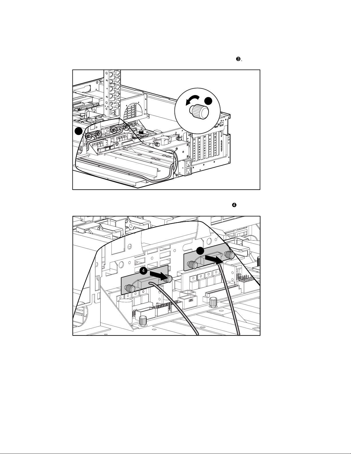
12. Remove the primary power supply cable
and the redundant power supply cable from
the two rear power outlets. Cut the plastic tie wrap securing the cable if there is one.
NOTE: The redundant power supply cable has been removed from figure 2-38.
4
3
Figure 2-38. Removing the power supply cables
13. Loosen the four thumbscrews securing the power supply cables to the power backplane
board assembly
. Cut the plastic tie wrap securing the cable to the chassis if there is one.
14. Remove the power supply. See “Hot-Plug Power Supply” earlier in this chapter.
NOTE: The system I/O board has been removed for clarity.
5
5
Figure 2-39. Loosening the four thumbscrews on the power backplane board assembly
Page 60

Removal and Replacement Procedures 2-43
15. Unplug the two AC power cords from the power backplane board.
Figure 2-40. Unplugging the two AC power cords from the power backplane board
16. Disconnect all the remaining cables from the power backplane board assembly.
17. Loosen the three thumbscrews securing the power backplane board assembly
the chassis.
18. Slide the assembly forward and then out of the chassis
6
7
Figure 2-41. Removing the power backplane board assembly
.
Reverse steps 1 through 18 to replace the power backplane board assembly.
to
Page 61

2-44 Compaq ProLiant 6400R Maintenance and Service Guide
Side Access Panel
To remove the side access panel,
1. Perform the preparation procedures. See “Preparation Procedures” earlier in this chapter.
2. Remove all processors, RPPMs, and terminator modules. See “Processors, Processor
Terminator Modules, and Processor Power Modules” earlier in this chapter.
3. Loosen the two thumbscrews securing the side access panel to the chassis
4. Remove the side access panel
1
Figure 2-42. Removing the side access panel (inside view)
Reverse steps 1 through 4 to replace the side access panel.
.
1
2
.
System Board and Tray
CAUTION: Carefully remove the system board and tray to avoid dislodging components from
the system board.
To remove the system board and tray:
1. Perform the preparation procedures. See “Preparation Procedures” earlier in this chapter.
2. Remove the PCI Hot Plug basket insulator. See “PCI Hot Plug Basket Insulator” earlier in
this chapter.
3. Remove all processors, redundant PPMs, and terminator modules. See “Processors,
Processor Terminator Modules, and Processor Power Modules” earlier in this chapter.
4. Remove the memory board. See “Memory Board” in the section entitled “Memory” earlier
in this chapter.
5. Remove the peripheral board. See “Peripheral Board” earlier in this chapter.
6. Disconnect any remaining cables from the system board.
Page 62

Removal and Replacement Procedures 2-45
7. Remove the side access panel. See “Side Access Panel” earlier in this chapter.
8. Loosen the three thumbscrews securing the system board and tray to the chassis
9. Pull the system board and tray approximately ½ inch toward the front of the chassis, and
slide it out through the side access panel
2
Figure 2-43. Removing the system board and tray
Reverse steps 1 through 9 to replace the system board and tray.
.
1
.
AC Power Cord and Plug Assembly
To remove the AC power cord and plug assembly,
1. Perform the preparation procedures. See “Preparation Procedures” earlier in this chapter.
2. Remove all hot-plug power supplies. See “Hot-Plug Power Supply” earlier in this chapter.
3. Remove I/O fans 1 and 2. See “I/O Hot-Plug Fans” earlier in this chapter.
Page 63

2-46 Compaq ProLiant 6400R Maintenance and Service Guide
4. Loosen the captive thumbscrew
.
5. Rotate the PCI card guide into the up position, and then swivel it away from the chassis
1
2
Figure 2-44. Rotating the PCI card guide into the up position
6. Remove all PCI expansion boards and the PCI Hot Plug basket insulator. See “PCI Hot
Plug Basket Insulator” earlier in this chapter.
.
7. Remove all processors, PPMs, and terminator modules. See “Processors, Processor
Terminator Modules, and Processor Power Modules” earlier in this chapter.
8. Remove the power supply. See “Hot-Plug Power Supply” earlier in this chapter.
9. Remove the memory board. See “Memory Board” in the section entitled “Memory” earlier
in this chapter.
10. Remove the peripheral board. See “Peripheral Board” earlier in this chapter.
11. Remove the side access panel. See “Side Access Panel” earlier in this chapter.
12. Remove the system board and tray. See “System Board and Tray” earlier in this chapter.
CAUTION: Carefully remove the system board and tray to avoid dislodging components from
the system board.
13. Cut and remove the cable tie securing the AC power cord to the chassis.
Page 64
Removal and Replacement Procedures 2-47
14. Loosen the four thumbscrews securing the AC power cord brackets
3
3
Figure 2-45. Removing the AC power cord brackets
15. Unplug the two AC power cords from the power backplane board
.
.
4
4
Figure 2-46. Unplugging the two AC power cords from the power backplane board
16. Remove the AC power supply cables. See “Power Backplane Board Assembly” earlier in
this chapter.
Page 65

2-48 Compaq ProLiant 6400R Maintenance and Service Guide
17. Remove the T-15 green ground wire screw from the plug assembly
, and lift the cover
up and away from the plug assembly.
5
5
Figure 2-47. Removing the T-15 green ground wire screw from the plug assembly
18. Remove the two T-15 screws securing the power supply connector to the chassis
push in the plug assembly
.
, then
NOTE: The external rear fan has been removed for clarity.
6
7
Figure 2-48. Removing the AC power supply connector from the chassis
Page 66

Removal and Replacement Procedures 2-49
19. Lift the AC power cord and plug assembly out of the chassis
8
Figure 2-49. Removing the AC power cord and plug assembly from the chassis
Reverse steps 1 through 19 to replace the AC power cord and plug.
.
Replacement Battery
The replacement battery periodically must be changed to insure optimum performance.
WARNING: The computer contains an internal lithium manganese dioxide, a vanadium
pentoxide, or alkaline battery pack. A risk of fire and burns exists if the battery pack is not
handled properly. To reduce the risk of personal injury:
■ Do not attempt to recharge the battery.
■ Do not expose the battery to temperatures greater than 60°C.
■ Do not disassemble, crush, puncture, or dispose of the battery in fire or water. Do not short
the external contacts.
■ Replace the battery only with the Compaq spare designated for this product.
CAUTION: Batteries, battery packs, and accumulators should not be discarded with general
household waste. To recycle or dispose of them, use the public collection system or return
them to Compaq, your authorized Compaq Partners, or their agents.
To install the replacement battery,
1. Perform the preparation procedures. See “Preparation Procedures” earlier in this chapter.
2. Remove the top access panel. See “Top Access Panel” earlier in this chapter.
3. Remove the peripheral board. See “Peripheral Board” earlier in this chapter.
WARNING: Disconnect all the power cords to remove power from the system completely. You
must disconnect the power cord from the server before removing the peripheral board.
Page 67

2-50 Compaq ProLiant 6400R Maintenance and Service Guide
4. Remove the lithium battery from the peripheral board.
CAUTION: BIOS settings will be lost after the flat disk battery is removed. BIOS settings must
be reconfigured after the battery is replaced.
5. Snap the replacement battery into the battery connector on the peripheral board.
Figure 2-50. Installing the replacement battery
6. Place the sticker included with your battery kit on the back of your server above the power
connector.
7. Run the Compaq System Configuration Utility to reconfigure the system. See Chapter 3,
“Diagnostics and Troubleshooting,” for more information.
Page 68

Chapter 3
Diagnostics and Troubleshooting
This chapter describes software and firmware diagnostic tools available for all Compaq server
products. The sections in this chapter are:
■ Diagnostic Tools Utility Overview
■ Default Configuration
■ Utilities Access
■ Power-On Self-Test (POST)
■ Diagnostics Software
■ Array Diagnostic Utility (ADU)
■ Integrated Management Log
■ Rapid Error Recovery
■ Remote Service Features
■ ROMPaq Error Recovery Options
■ Compaq Insight Manager
Diagnostic Tools Utility Overview
These utilities were developed to assist in diagnosing problems, testing the hardware, and
monitoring and managing Compaq server hardware.
Page 69

3-2 Compaq ProLiant 6400R Maintenance and Service Guide
Diagnostic Tools
Tool What it is How to run it
Table 3-1
Compaq Diagnostics
Program
Compaq Inspect
Utility
Compaq Insight
Manager
Compaq Survey
Utility
Utility to assist testing and verification of
operation of Compaq hardware. If
problems are found, Compaq
Diagnostics isolates failure down to
replaceable part, whenever possible.
The Inspect utility provides a report
detailing system information.
A client/server application used to
manage Compaq hardware remotely in a
network environment. Reports hardware
fault conditions (both failure and
prefailure) and collects data for reports
and graphs.
An online information-gathering agent
that runs on servers, gathering critical
hardware and software information from
various sources. A utility for servers
running Windows NT or NetWare.
If a significant change occurs between
data gathering intervals, previous
information is marked, and the survey
text file is overwritten to reflect the
latest configuration and changes since
the last configuration. This allows a
historical record of change events for
server hardware and software.
Diagnostics and Utilities are located on
the system partition on the hard drive
and must be accessed when a system
configuration error is detected during
Power-On Self-Test (POST). Compaq
Diagnostics software is also available on
the Compaq SmartStart and Support
Software CD. A Diagnostics diskette can
be created from SmartStart and Support
Software CD, and Diagnostics can be
run from diskette.
The Inspect utility can be run from either
the main menu of the System
Configuration Utility or the Compaq
Diagnostics program.
For more information, refer to the
Compaq Management CD and the
Compaq Insight Manager User Guide.
More information on viewing and
printing the event list can be found in
the Compaq Insight Manager section of
this chapter.
Install Survey from SmartStart, Compaq
Integration Maintenance Utility, or
Compaq Management CD.
continued
Page 70

Table 3-1
Diagnostic Tools
Tool What it is How to run it
continued
Diagnostics and Troubleshooting 3-3
Array Diagnostics
Utility (ADU)
Drive Array
Advanced
Diagnostics
Integrated
Management Log
A Windows-based tool designed to run
on all Compaq systems that support
Compaq array controllers. Two main
functions of ADU are to collect all
possible information about the array
controllers in the system and generate a
list of detected problems.
The tool is available for all Compaq
servers covered by this guide.
The predecessor to ADU, DAAD is a tool
based on the disk operating system
(DOS) for Compaq servers with Smart
Array Controllers. DAAD collects
information about the array controllers in
the system and offers a list of detected
problems.
A log of system events, such as system
failures or nonfatal error conditions.
View events in the Integrated
Management Log
■ On the Integrated Management
Display
■ From within Compaq Insight
Manager
■ From within Compaq Survey Utility
Use the information provided in the
“Array Diagnostics Utility” later in this
chapter.
For a list of Compaq servers still
supported by the tool, visit the Compaq
website:
http://www.compaq.com
The Integrated Management Log
requires Compaq operating
system-dependent drivers. Refer to
Compaq Support Software CD for
instructions on installing the appropriate
drivers.
System
Configuration Utility
Utility to easily configure the hardware
installed in or connected to the server.
Specifically, it can
■ Resolve resource conflicts in areas
such as memory, port addresses,
and interrupt requests (IRQs)
■ Configure PCI boards automatically
■ Provide switch and jumper settings
■ Manage installation of memory,
processor upgrades, and mass
storage devices, such as hard
drives, tape drives, and diskette
drives
■ Store configuration information in
nonvolatile memory
■ Assist in installation of an operating
system
■ Assist in running diagnostic tools,
such as TEST and INSPECT
If the server has bootable CD-ROM drive,
run Compaq System Configuration Utility
directly from Support Software CD
supplied with SMART Controller Option
Kit or SmartStart and Support
Software CD supplied with server. Use
the CD supplied for the latest version
supporting the SMART Controller.
If the server does not have a bootable
CD-ROM drive, create diskettes with
latest version of the System
Configuration Utility from Support
Software CD or SmartStart and Support
Software CD.
Page 71

3-4 Compaq ProLiant 6400R Maintenance and Service Guide
Default Configuration
When the system is first turned on, the system ROM detects the unconfigured state of the
hardware and provides default configuration settings for most devices. By providing this
initialization, the system can run Diagnostics and other software applications before running the
normal SmartStart and System Configuration programs.
Default Configuration Messages
IMPORTANT: A choice to format and partition the boot drive before running SmartStart and the System
Configuration programs may prohibit creating a System Partition and the offline remote management
features that it provides.
If you insert a System Configuration, Diagnostics, or SmartStart and Support Software CD into
the CD-ROM drive before to powering on the server, the system ROM boots to that utility. If
the system ROM does not detect one of the CDs, you will be prompted for the intended
operating system. The system reboots if any operating system-dependent configurations have
changed with the new operating system selection. If the selected configurations are the same as
the current configurations, the system boots normally. If you enter a wrong choice, on
subsequent reboots you may change the operating system.
Inspect Utility
The Inspect Utility provides configuration information, such as the contents of the operating
system startup files, current memory configuration, ROM version, and Integrated Management
Log information. The utility operates with Microsoft DOS and in the MS-DOS emulation mode
of MS OS/2.
Running the Inspect Utility
Printing the Inspect Listing
Select Print on the Inspect screen to print a copy of the Inspect list. Keep a copy of the list with
each server for later reference.
1. Turn the server off and then back on. Then press F10 when the cursor appears in the upper
right corner of the screen.
2. At the main menu, select Diagnostics and Utilities.
3. Press Enter.
4. Select Inspect Computer, and press Enter.
NOTE: If Diagnostics is not installed on the hard drive, System Configuration prompts you to insert the
Diagnostics diskette in drive A.
5. Follow the instructions. The first time the Inspect Utility displays, select Entire System
and press Enter.
Page 72

Utilities Access
The Compaq SmartStart and Support Software CD contains the SmartStart program and many
of the Compaq utilities needed to maintain the system, including
■ System Configuration Utility
■ Array Configuration Utility
■ Array Diagnostic Utility
■ ROMPaq Firmware Upgrade Utilities
■ Compaq Diagnostics
CAUTION: Do not select the Erase Utility when running the SmartStart and Support
Software CD. This will result in data loss to the entire system.
Running Compaq Utilities
There are three ways from which to access Compaq Utilities:
■ System partition
Diagnostics and Troubleshooting 3-5
■ Diskette
■ Compaq SmartStart and Support Software CD
Running the Utilities from the System Partition
If the system was installed using SmartStart, the Compaq utilities will automatically be
available on the system partition. The system partition could also have been created during a
manual system installation.
To run the utilities on the system partition, start the system and press F10 when you see
Press F10 for system partition utilities.
Then select the desired utility from the menu
■ The System Configuration Utility is available under the System Configuration menu.
■ The Array Configuration Utility is available under the System Configuration menu.
■ Compaq Diagnostics (Test and Inspect) are available under the Diagnostics and Utilities
menu.
■ The ROMPaq Firmware Upgrade Utility is available under the Diagnostics and Utilities
menu.
Running the Utilities from Diskette
Run the utilities from their individual diskettes. If you have a utility diskette newer than the
version on the SmartStart and Support Software CD, use that diskette.
Create a diskette version of the utility from the SmartStart and Support Software CD.
Page 73

3-6 Compaq ProLiant 6400R Maintenance and Service Guide
To create diskette versions of the utilities from the CD,
1. Boot the Compaq SmartStart and Support Software CD.
2. From the Compaq System Utilities screen, select Create Support Software Disks, and then
select Next.
3. Select the diskette you would like to create from the list, and then follow the instructions
on the screen.
Running the Utilities from the Compaq SmartStart and Support
Software CD
IMPORTANT: Only the System Configuration Utility, and Array Configuration Utility, and the Array
Diagnostic Utility can be executed from the Compaq SmartStart and Support Software CD. All other
utilities must be executed from the system partition or from the diskette.
To run these utilities directly from the Compaq SmartStart and Support Software CD,
4. Boot the Compaq SmartStart and Support Software CD.
5. From the Compaq System Utilities screen, select the utility you wish to run, and then
select Next.
G To execute the System Configuration Utility, select Run System Configuration Utility.
G To execute the Array Configuration Utility, select Run Array Configuration Utility.
G To execute the Array Diagnostic Utility, select Run Array Diagnostic Utility.
Power-On Self-Test
POST is a series of diagnostic tests that run automatically on Compaq computers when the
system is turned on. POST checks the following assemblies to ensure that the computer system
is functioning properly:
■ System ROM
■ Keyboard
■ Power supply
■ System board
■ Memory
■ Memory expansion boards
■ Controllers
■ Diskette drives
■ Hard drives
■ PPMs
■ Fans
Page 74

Error Messages of the Power-On Self-Test
An error in the system found by the POST is indicated by an audible or visual message. If an
error code displays on the screen during POST or after a reset of the system, use the instructions
in Table 3-2.
NOTE: Many of the actions in Table 3-2 require you to run Diagnostics or the Compaq System
Configuration Utility. The steps for running the utilities are after Table 3-2.
In Table 3-2, the Recommended Action column lists the steps necessary to correct the error.
After completing each step, run the Diagnostics program to verify whether the error has been
corrected. If the error code reappears, perform the next step, and then re-run the Diagnostics
program. Follow this procedure until Diagnostics no longer detects an error.
Error Code Audible Beeps Probable Source of Error Recommended Action
Diagnostics and Troubleshooting 3-7
Table 3-2
POST Error Messages
A Critical Error
occurred prior to this
power-up
Unsupported
Processor Detected
System Halted
FATAL ROM ERROR:
The System ROM is
not properly
programmed
101-ROM Error 1 long, 1 short System ROM checksum Run Diagnostics. Replace the
101-I/O ROM Error None Options ROM checksum Run Diagnostics. Replace the
102-System Board
Failure
104-ASR-2 Timer
Failure
105-Current System
ROM is corrupt –
now booting
redundant System
ROM
None A catastrophic system error,
which caused the server to crash
has been logged.
1 long, 1 short Processor not supported by
current system ROM.
1 long, 1 short ROM was programmed in the
factory incorrectly.
None Direct Memory Access (DMA)
timers, and so on
None System board failure Run Diagnostics. Replace the
2 long Nonbooted ROM image is
corrupt.
Run Diagnostics. Replace the
failed assembly as indicated.
Check documentation for
supported processors, and, if
supported, remove the
processor and update the
system to latest ROM.
Replace the physical ROM part.
failed assembly as indicated.
failed assembly as indicated.
Replace the system board. Run
the Compaq System
Configuration Utility.
failed assembly as indicated.
Flash the ROM utilizing
ROMPaq.
162-System Options
Not Set
163-Time & Date Not
Set
2 short Incorrect configuration Run the System Configuration
Utility and correct.
2 short Invalid time or date in
configuration memory
Run the System Configuration
Utility and correct.
continued
Page 75

3-8 Compaq ProLiant 6400R Maintenance and Service Guide
Table 3-2
POST Error Messages
Error Code Audible Beeps Probable Source of Problem Recommended Action
continued
164-Memory Size
Error
172-Configuration
Nonvolatile Memory
Invalid
173-Slot ID
Mismatch
174-Configuration/
Slot Mismatch Device
Not Found
175-Configuration/
Slot Mismatch Device
Found
177-Configuration
Not Complete
178-Processor
Configuration Invalid
180-Log Reinitialized None
201-Memory Error None RAM failure Run Diagnostics. Replace the
203-Memory
Address Error
2 short Incorrect configuration memory. Run the System Configuration
Utility and correct.
None Corrupt nonvolatile configuration
or jumper installed
None Board replaced, configuration not
updated.
None EISA or PCI board not found Run the System Configuration
None EISA or PCI board added,
configuration not updated.
None Incomplete system configuration Run the System Configuration
None Processor type or step does not
match configuration memory.
None RAM failure Run Diagnostics. Replace the
Run the System Configuration
Utility and correct.
Run the System Configuration
Utility and correct.
Utility and correct.
Run the System Configuration
Utility and correct.
Utility and correct.
Run the System Configuration
Utility and correct.
failed assembly as indicated.
failed assembly as indicated.
207-Invalid Memory
Configuration Check DIMM [SIMM]
Installation
208-Invalid Memory
Speed – Check DIMM
[SIMM] Installation
209-Memory
Detection Failure.
Check Memory
Installation
211-Cache Switch
Set Incorrectly
None Memory module installed
incorrectly.
1 long, 1 short The speed of the memory is too
slow:
■ xx00 = expansion board
SIMMs are too slow.
■ 00yy = system board SIMMs
are too slow.
■ xx and yy have a
corresponding bit set.
1 long, 1 short Unable to size memory Check DIMM installation. If error
None Switch not set properly during
installation or upgrade.
Verify the placement of memory
modules.
The speed of the memory
modules must be 60 ns. Verify
the speed of the memory
modules installed, and replace
them if slower than 60 ns.
persists, call Compaq service
provider.
Verify switch settings.
continued
Page 76

Diagnostics and Troubleshooting 3-9
Table 3-2
POST Error Messages
Error Code Audible Beeps Probable Source of Problem Recommended Action
continued
212-System
Processor Failed/
Mapped out
214-DC-DC
Converter Failed
214-Processor PPM
Failed Module X
215-Processor Power
Module has lost
Redundancy in
Socket x
215-Nonfunctioning
Voltage Regulator
Module for
Processors
216-Voltage
Regulator Module for
Processor X no
longer redundant
216-Processor PPM
has lost Redundancy,
Module X
218-Cache
Accelerators Not
Installed. System
Halted.
1 short Processor in slot x failed. Run Diagnostics. Replace the
failed processor.
None PowerSafe Module (DC-DC
Converter) failed.
None Indicated PPM (DC-DC Converter)
failed.
None PPM (DC-DC Converter) has lost
redundancy.
None PPM (DC-DC Converter) has
failed or lost redundancy.
None Redundancy failed in PPM. Replace the PPM.
None Indicated PPM (DC-DC Converter)
has lost redundancy.
None Cache accelerators not installed
or improperly installed.
Run Diagnostics. Replace the
failed assembly as indicated.
Replace the failed assembly as
indicated.
Run Diagnostics. Replace the
failed assembly as indicated.
Run Diagnostics. Replace the
failed assembly as indicated.
Replace the failed assembly as
indicated.
Check cache accelerator
installation.
219-Tag Update
Rules SRAM Failure.
System Halted
219-Snoop Rules
SRAM Failure.
System Halted.
220-Cache
Accelerator Slot x
Initialization Failed.
System Halted.
221-Power Fault On
Processor Bus X
301-Keyboard Error None Keyboard failure Turn off the computer, and then
301-Keyboard Error
or Test Fixture
Installed
None Catastrophic chipset failure. Call Compaq service provider.
None Catastrophic chipset failure. Call Compaq service provider.
None Cache accelerator in slot x
improperly installed or failed.
None A PPM on the indicated bus is in
a failed state.
None Keyboard failure Replace the keyboard.
Check cache accelerator
installation. If properly installed,
replace it.
Run Diagnostics. Replace the
failed assembly as indicated.
reconnect the keyboard.
continued
Page 77

3-10 Compaq ProLiant 6400R Maintenance and Service Guide
Table 3-2
POST Error Messages
Error Code Audible Beeps Probable Source of Problem Recommended Action
continued
ZZ-301-Keyboard
Error
303-Keyboard
Controller Error
304-Keyboard or
System Unit Error
40X-Parallel Port X
Address Assignment
Conflict
601-Diskette
Controller Error
605-Diskette Drive
Type Error
None Keyboard failure. (ZZ represents
the Keyboard Scan Code.)
None System board, keyboard, or
mouse controller failure
None Keyboard, keyboard cable, or
system board failure
2 short Both external and internal ports
are assigned to parallel port X.
None Diskette controller circuitry
failure
2 short Mismatch in drive type Run the System Configuration
1. Free the stuck key.
2. Replace the keyboard.
1. Run Diagnostics.
2. Replace failed assembly
as indicated.
1. Make sure the keyboard is
attached.
2. Run Diagnostics to
determine which is in
error.
3. Replace the part indicated.
Run the System Configuration
Utility and correct.
1. Make sure the diskette
drive cables are attached.
2. Replace the diskette drive
and/or cable.
3. Replace the system board.
Utility to set the diskette type
correctly.
1151-Com Port 1
Address Assignment
Conflict
1152-Com Port 2, 3,
or 4 Address
Assignment Conflict
1610-Temperature
violation detected.
Waiting for system to
cool
1611-Fan failure
detected
1611-I/O Fan (Fan X)
failure detected
2 short Both external and internal serial
ports are assigned to COM1.
2 short Both external and internal serial
ports are assigned to COM2,
COM3, or COM4.
2 short Ambient system temperature is
too hot.
2 short Required fan not installed or
spinning
2 short I/O fan 1, 2, 3, or 4 has failed. Replace the failed fan.
Run the System Configuration
Utility and correct.
Run the System Configuration
Utility and correct.
Check fan in system
environment.
Check fans.
continued
Page 78

Diagnostics and Troubleshooting 3-11
Table 3-2
POST Error Messages
Error Code Audible Beeps Probable Source of Problem Recommended Action
continued
1611-I/O Fan (Fan 5)
failure detected
Processor X
initialized at 550/100
System fans not
redundant
1611-CPU Fan
(Fan X) failure
detected
1612-Primary power
supply failure
1613-Low System
Battery
1615-Power Supply
Failure, Power
Supply Unplugged, or
Power Supply Fan
Failure in Bay X
1617-Fan controller
not responding
1617-I/O Fan
controller not
responding
2 short I/O fan 5 or 6 has failed. Replace the failed fan.
None Processors upgraded to
550-MHz, but external hot-plug
rear CPU fan not replaced with
external rear hot-plug system fan
assembly
2 short CPU fan has failed. Replace the failed fan.
2 short Primary power supply has failed. Replace power supply as soon
None Real-time clock system battery is
running low on power.
None A power supply has failed. Replace or check the specified
2 short Fan controller failure Check and replace the failed
2 short I/O fan controller failure Check and replace the failed
Verify that the correct fan
assembly was installed properly
and that the switch settings are
correct (SW1, position 3). Check
for fan failure, and replace if
needed.
as possible.
Run Diagnostics. Replace the
failed assembly as indicated.
power supply.
controller assembly.
controller assembly.
1617-CPU Fan
controller not
responding
1618-PCI slots
powered down.
Check PCI hot plug
enabler connectors.
1620-Locked SCSI
Bus Detected. Verify
SCSI bus cabling.
System halted.
1621-Current SCSI
bus cable
configuration is not
recommended
2 short CPU fan controller failure Check and replace the failed
controller assembly.
None PCI hot plug enabler is missing or
failed.
None SCSI bus failure Run Diagnostics. Replace the
None Improper SCSI bus cabling Check the documentation for
Check and replace the missing
or failed assembly.
failed assembly as indicated.
the proper SCSI bus cabling.
continued
Page 79

3-12 Compaq ProLiant 6400R Maintenance and Service Guide
Table 3-2
POST Error Messages
Error Code Audible Beeps Probable Source of Problem Recommended Action
continued
1622-Internal SCSI
Jumper Board Not
Installed
1703-SCSI cable
error detected.
Internal SCSI cable
not attached to
system board
connector. System
halted.
1720-Slot x Drive
Array – SMART Drive
Detects Imminent
Failure SCSI: Port y:
SCSI ID x
1724-Slot x Drive
Array – Physical
Drive Position
Change(s) Detected –
Logical drive
configuration has
automatically been
updated
None The system has detected that the
array enabler board is not
installed.
None Incorrect cabling Ensure that the integrated SCSI
None Indicated drive has reported a
SMART predictive-failure
condition and may fail later.
None Logical drive configuration has
been updated automatically after
physical drive position changes.
Install the array enabler board.
controller has the SCSI
termination attached.
If the drive is part of a
nonfault-tolerant configuration,
back up all data before
replacing the drive and restore
all data afterward. If the drive is
part of a fault-tolerant
configuration do not replace it
unless all other drives in the
array are online. Press F1 to
resume.
Press F1 to resume.
1726-Slot x Drive
Array – Array
Accelerator Memory
Size Change
Detected
1727-Slot x Drive
Array – New Logical
Drive(s) Attachment
Detected. If more
than 32 logical
drives, this message
will be followed by:
Auto-configuration
failed: Too many
logical drives.
1730-Fixed Disk 0
does not support
DMA Mode.
None Array accelerator configuration
has been updated automatically
because the replacement of the
array accelerator (or controller)
with one with a different memory
size.
None Controller has detected an
additional array of drives that
was attached when the power
was off. The logical drive
configuration information has
been updated to add the new
logical drives. The maximum
number of logical drives
supported is 32. Additional
logical drives will not be added to
the configuration.
None Hard drive error Run the System Configuration
Press F1 to resume.
Press F1 to resume.
Utility and correct.
continued
Page 80

Diagnostics and Troubleshooting 3-13
Table 3-2
POST Error Messages
Error Code Audible Beeps Probable Source of Problem Recommended Action
continued
1731-Fixed Disk 1
does not support
DMA Mode.
1740-Fixed Disk 0
failed Set Block
Mode command
1741-Fixed Disk 1
failed Set Block
Mode command
1750-Fixed Disk 0
failed Identify
command
1751-Fixed Disk 1
failed Identify
command
1760-Fixed Disk 0
does not support
Block Mode
1761-Fixed Disk 1
does not support
Block Mode
1764-Slot x Drive Array - Capacity Expansion Process is temporarily disabled,
followed by one of the following.
■ Expansion will resume when Array Accelerator has been reattached.
■ Expansion will resume when Array Accelerator has been replaced.
■ Expansion will resume when Array Accelerator RAM allocation is successful.
■ Expansion will resume when Array Accelerator battery reaches full charge.
■ Expansion will resume when automatic data recovery has been completed.
None Hard drive error Run the System Configuration
None Hard drive error Run the System Configuration
None Hard drive error Run the System Configuration
None Hard drive error Run the System Configuration
None Hard drive error Run the System Configuration
None Hard drive error Run the System Configuration
None Hard drive error Run the System Configuration
Utility and correct.
Utility and correct.
Utility and correct.
Utility and correct.
Utility and correct.
Utility and correct.
Utility and correct.
Reattach or replace array
accelerator. Wait until the array
accelerator batteries have
charged or for automatic data
recovery to complete, as
indicated.
1765-Slot x Drive Array Option ROM Appears to Conflict With an ISA Card. ISA
cards with 16-bit memory cannot be configured in memory range C0000 to DFFFF
along with the SMART-2/E 8-bit Option ROM due to EISA bus limitations. Please
remove or reconfigure the ISA card.
1766-Slot x Drive Array requires System ROM Upgrade. Run Systems ROMPaq
Utility.
Remove or reconfigure
conflicting ISA cards. Disable
the shared memory on any ISA
network cards that may be
installed.
Run the latest Systems ROMPaq
Utility to upgrade the System
ROMs.
continued
Page 81

3-14 Compaq ProLiant 6400R Maintenance and Service Guide
Table 3-2
POST Error Messages
Error Code Audible Beeps Probable Source of Problem Recommended Action
continued
1767-Slot x Drive Array Option ROM is Not Programmed Correctly or may Conflict
with the Memory Address Range of an ISA Card. Check the Memory Address
Configuration of installed ISA Card(s) or run Options ROMPaq Utility to attempt
SMART-2/E Option ROM Reprogramming.
1768-Slot x Drive
Array-Resuming
logical drive
expansion process.
1769-Slot x Drive
Array - Drive(s)
disabled due to
failure during
expand. Select F1 to
continue with logical
drives disabled.
Select F2 to accept
data loss and to
re-enable logical
drives.
1771-Primary Disk
Port Address
Assignment Conflict
None SMART-2 Controller error. A
controller reset or power cycle
occurred during the expansion.
None SMART-2 Controller error. Data
lost while expanding the array.
The drives have been temporarily
disabled.
None Internal and external hard drive
controllers are both assigned to
the primary address.
Remove or reconfigure
conflicting ISA cards, especially
any not recognized by the
System Configuration Utility.
Reprogramming the ROM on the
SMART-2/E Controller, using the
latest Options ROMPaq
(version 2.29 or later).
No action required.
Press F2 to accept the data loss
and re-enable the logical drives.
Restore data from the backup.
Run the System Configuration
Utility and correct.
1772-Secondary
Disk Port Address
Assignment Conflict
1773-Primary Fixed
Disk Port Assignment
Conflict
None Address assignment conflict.
Internal and external hard drive
controllers are both assigned to
the secondary address.
None Fixed-disk drive error Run the System Configuration
Run the System Configuration
Utility and correct.
Utility and correct.
continued
Page 82

Diagnostics and Troubleshooting 3-15
Table 3-2
POST Error Messages
Error Code Audible Beeps Probable Source of Problem Recommended Action
continued
1774-Slot x Drive
Array - Obsolete data
found in Array
Accelerator.
Select F1 to discard
contents of Array
Accelerator.
Select F2 to write
contents of Array
Accelerator to drives.
1775-Slot x Drive
Array - ProLiant
Storage System Not
Responding SCSI
Port (y): Check
storage system
power switch and
cables. Turn the
system power off
while checking the
ProLiant power and
cable connections,
then turn the system
power back on to
retry.
1776-Drive Array SCSI Port
Termination Error
None SMART-2 Controller error. Data
found in the array accelerator are
older than data found on drives.
None Storage system error Turn off power to system.
None External and internal SCSI drives
are both configured to port 1.
Press F1 to discard the older
data in the array accelerator
and retain the newer data on
the drives.
Check the external ProLiant
power switch. External drives
must all be powered up before
or at the same time as the main
system. Check the cables. If a
retry does not help, replace the
cable, ProLiant firmware,
ProLiant backplane, or Smart
Array Controller.
Reconfigure drives.
1777-Drive Array
External Drive
Subsystem Error
1778-Drive Array
resuming Automatic
Data Recovery
process
1779-Drive Array
Controller detects
replacement drives
1780-Disk 0 Failure None Hard drive/format error Run Diagnostics. Replace the
1781-Disk 1 Failure None Hard drive/format error Run Diagnostics. Replace the
None Cooling fan failure, internal
temperature alert, or open side
panel
None A controller reset or power cycle
occurred during automatic data
recovery.
None Intermittent drive failure and/or
possible loss of data
Inspect for cooling fan failure or
open side panel.
No action necessary.
If this message appears and
drive X has not been replaced,
an intermittent drive failure has
occurred. This message also
appears once immediately after
drive replacement whenever
data must be restored from the
backup.
failed assembly as indicated.
failed assembly as indicated.
continued
Page 83

3-16 Compaq ProLiant 6400R Maintenance and Service Guide
Table 3-2
POST Error Messages
Error Code Audible Beeps Probable Source of Problem Recommended Action
continued
1782-Disk Controller
Failure
1783-Slot x Drive
Array Controller
Failure
1784-Drive Array
Drive Failure,
Physical Drive
None Hard disk drive circuitry error Run Diagnostics. Replace the
failed assembly as indicated.
None ROM installation problem or array
accelerator board problem. If this
message appears immediately
after a ROM installation, the ROM
is defective or not installed
properly.
None Defective drive and/or cables Check for loose cables. Replace
Check to see if
■ The array accelerator board
is attached properly.
■ The array controller is firmly
inserted in its slot.
If an error recurs, upgrade the
System ROMs. Otherwise,
replace the Smart Array
Controller.
defective drive X and/or cables.
continued
Page 84

Diagnostics and Troubleshooting 3-17
Table 3-2
POST Error Messages
Error Code Audible Beeps Probable Source of Problem Recommended Action
continued
1785-Drive Array not
Configured
Run Compaq Array
Configuration Utility
No drives detected. Turn off system, and check
Array Accelerator
Memory Size
Increased.
External Cable(s)
Attached to Wrong
SCSI Port
Connector(s).
Drive positions
cannot be changed
during Capacity
Expansion.
Drive positions
appear to have
changed.
None Configuration error See actions below.
Run the Compaq Array
Configuration Utility.
SCSI cable connections to make
sure drives are attached
properly.
Run the Compaq System
Configuration Utility.
Turn system power off and
swap SCSI power connectors to
prevent data loss.
Run Array Diagnostic Utility if
previous positions are unknown.
Then turn system power Off and
move drives to their original
positions.
Run Array Diagnostic Utility if
previous positions are unknown.
Then turn the system power off,
and move the drives to their
original positions.
Configuration
information
indicates drive
positions beyond
the capability of
this controller. This
may be due to
drive movement
from a controller
that supports more
drives than the
current controller.
Configuration
information
indicates drives
were configured on
a controller with a
newer firmware
version.
Note: A bad power cable connection to the drive or noise on the data cable may cause a false 1788 error message.
If a bad power cable connection causes this error message and not because of an incorrect drive replacement, repair
the connection and press F2. If this message was not due to a bad power cable connection and no drive replacement
took place, this error message may indicate noise on the data cable. Check cable for proper routing.
To avoid data loss, turn the
system power off and reattach
the drives to the original
controller.
To avoid data loss, reattach the
drives to the original controller,
or upgrade the controller
firmware to the version of the
original controller, using Option
ROMPaq.
Press F1 to resume.
continued
Page 85

3-18 Compaq ProLiant 6400R Maintenance and Service Guide
Table 3-2
POST Error Messages
Error Code Audible Beeps Probable Source of Problem Recommended Action
continued
1786-Drive Array
Recovery Needed
The following drive(s)
need Automatic Data
Recovery: Drive X.
Select "F1" to
continue with
recovery of data to
drive(s).
Select "F2" to
continue without
recovery of data to
drive(s).
1787-Drive Array
Operating in Interim
Recovery Mode.
Physical drive
replacement needed:
Drive X
1788-Incorrect Drive
Replaced: Drive X
Drive(s) were
incorrectly replaced:
Drive Y Select "F1"
to continue - drive
array will remain
disabled. Select "F2"
to reset configuration
- all data will be lost.
None Interim Data Recovery mode.
Data have not been recovered
yet.
None Hard drive X failed, or a cable is
loose or defective. After a system
restart, this message reminds
you that drive X is defective and
fault tolerance is being used.
None Because the drives are not
installed in their original
positions, they have been
disabled. See note below.
Press F1 to allow automatic
data recovery to begin. Data will
automatically be restored to
drive X now that the drive has
been replaced or seems to
working.
-or-
Press F2. The system will
continue to operate in the
Interim Data Recovery mode.
1. Replace drive X as soon as
possible.
2. Check loose cables.
3. Replace defective cables.
Reinstall the drives correctly as
indicated.
Press F1 to restart the computer
with the drive array disabled.
-or-
Press F2 to use the drives as
configured and lose all the data
on them.
1789-Drive Not
Responding, Physical
Drive
Check cables or
replace physical
drive X.
Select "F1" to
continue - drive array
will remain disabled.
Select "F2" to fail
drive(s) that are not
responding -
Interim Recovery
Mode will be enabled
if configured for fault
tolerance.
None Cable or hard drive failure 1. Check the cable
connections.
2. Replace the cables.
3. Replace the drive. If you
do not want to replace the
drive now, press F2.
continued
Page 86

Diagnostics and Troubleshooting 3-19
Table 3-2
POST Error Messages
Error Code Audible Beeps Probable Source of Problem Recommended Action
continued
1790-Disk 0
Configuration Error
1791-Disk 1 Error None Hard drive error or wrong drive
1792-Drive Array
Reports Valid Data
Found in Array
Accelerator.
Data will
automatically be
written to drive array.
1793-Drive Array Array Accelerator
Battery Depleted Data Lost
(Error message 1794
also displays.)
1794-Drive Array Array Accelerator
Battery Charge Low.
Array Accelerator is
temporarily disabled.
Array Accelerator will
be re-enabled when
battery reaches full
charge.
None Hard drive error or wrong drive
type
type
None While the system was in use,
power was interrupted while data
were in the array accelerator
memory. Power was then
restored within 8 to 10 days, and
the data in the array accelerator
were flushed to the drive array.
None While the system was in use,
power was interrupted while data
were in the array accelerator
memory. Array accelerator
batteries failed. Power was not
restored within 8 to 10 days. The
data in the array accelerator
were lost.
None The battery charge is below
75%. Posted writes are disabled.
Run the System Configuration
Utility and Diagnostics and
correct.
Run the System Configuration
Utility and Diagnostics and
correct.
No action necessary because no
data were been lost. Perform
orderly system shutdowns to
avoid data remaining in the
array accelerator.
Perform orderly system
shutdowns to avoid data
remaining in the array
accelerator.
Replace the array accelerator
board if batteries do not
recharge within 36 power-on
hours.
1795-Drive Array Array Accelerator
Configuration Error.
Data does not
correspond to this
drive array. Array
Accelerator is
temporarily disabled.
1796-Drive Array Array Accelerator Not
Responding.
Array Accelerator is
temporarily disabled.
None While the system was in use,
power was interrupted while data
were in the array accelerator
memory.
The data stored in the array
accelerator do not correspond to
the drive array.
None Array accelerator is defective or
has been removed.
Match the array accelerator to
the correct drive array, or run
the System Configuration Utility
to clear the data in the array
accelerator.
Check that the array accelerator
is properly seated.
Run the System Configuration
Utility to reconfigure the
Compaq IDA-2 without the array
accelerator.
continued
Page 87

3-20 Compaq ProLiant 6400R Maintenance and Service Guide
Table 3-2
POST Error Messages
Error Code Audible Beeps Probable Source of Problem Recommended Action
continued
1797-Drive Array Array Accelerator
Read Error Occurred.
Data in Array
Accelerator has been
lost. Array
Accelerator is
disabled.
1798-Drive Array Array Accelerator
Write Error Occurred.
Array Accelerator is
disabled.
1799-Drive Array Drive(s) Disabled due
to Array Accelerator
Data Loss.
Select "F1" to
continue with logical
drives disabled.
Select "F2" to accept
data loss and to
re-enable logical
drives.
Beeps only: 2 Long 2 long No valid memory is present in
None Hard parity error while reading
data from posted-writes
memory.
None Hard parity error while writing
data to posted-writes memory.
None Volume failed because of data
loss in posted-writes memory.
the system.
Enable array accelerator.
Enable array accelerator.
Press F1 to continue with
logical drives disabled or F2 to
accept the data loss and
re-enable the logical drive.
Replace the failed memory with
valid memory.
Beeps only: 2 Long +
2 Short
(Run System
Configuration Utility F10 key)
(RESUME - F1 key) None As indicated to continue
Diagnostics Software
Table 3-3 through 3-17 include all test error codes generated by Compaq products. Each code
has a corresponding description and recommended action. Each system generates only the codes
that apply to its configuration and options.
When you select Diagnostics and Utilities from the System Configuration Utility main menu,
the utility prompts you to test, inspect, upgrade, and diagnose the server.
Diagnostics and Utilities are located on the system partition on the hard drive and must be
accessed when a system configuration error is detected during the Power-On Self-Test (POST).
Compaq Diagnostics software is also available on the Compaq SmartStart and Support
Software CD. You can create a Diagnostics diskette from the SmartStart and Support
Software CD and run Diagnostics from diskette. See the procedure in the “Running Compaq
Utilities” section earlier in this chapter.
2 long, 2 short Power is cycled. Temperature is
too hot. Processor fan not
installed or spinning.
None A configuration error occurred
during POST.
Check fans.
Press F10 to run the System
Configuration Utility.
Press F1.
Page 88

The following options are available from the Diagnostics and Utilities menu:
■ Test Computer
■ Inspect Computer
■ Upgrade Firmware
■ Remote Utilities
■ Diagnose Drive Array
Diagnostic error codes are generated when the Diagnostics software recognizes a problem.
These error codes help identify possible defective subassemblies.
Steps for Diagnostics
In each case, in the tables the “Recommended Action” column lists the steps necessary to
correct the problem. After completing each step, run the Diagnostics utility to verify that the
error condition has been corrected. If the error code reappears,
1. Perform the next step listed in the table.
2. Run the Diagnostics program again.
3. Follow this procedure until the Diagnostics program no longer detects an error.
Diagnostics and Troubleshooting 3-21
Page 89

3-22 Compaq ProLiant 6400R Maintenance and Service Guide
100 – 199, Primary Processor Test Error Codes
The 100 series of diagnostic error codes identifies failures with processor and system board
functions.
Table 3-3
Primary Processor Test Error Codes
Error Code Description Recommended Action
101-xx CPU test failed. Replace the processor board and retest.
103-xx DMA page registers test failed.
104-xx Interrupt controller master test
failed.
105-xx Port 61 error.
106-xx Keyboard controller self-test
failed.
107-xx CMOS RAM test failed.
108-xx CMOS interrupt test failed.
109-xx CMOS clock load data test failed.
110-xx Programmable timer load data test
failed.
111-xx Refresh detect test failed.
112-xx Speed test slow mode out of range
113-xx Protected mode test failed.
114-xx Speaker test failed. 1. Verify the speaker connection and retest.
116-xx Cache test failed. Replace the system board and retest.
122-xx Multiprocessor dispatch test
failed.
123-xx Interprocessor communication test
failed
Replace the processor board and retest.
1. Replace the battery and clock module and retest.
2. Replace the system board and retest.
Replace the processor board and retest.
2. Replace the speaker and retest.
3. Replace the system board and retest.
1. Check the system configuration and retest.
2. Replace the processor board and retest.
3. Replace the system board and retest.
199-xx Installed devices test failed. 1. Check the system configuration and retest.
2. Verify cable connections and retest.
3. Check switch and/or jumper settings and retest.
4. Run the Configuration Utility and retest.
5. Replace the processor board and retest.
6. Replace the system board and retest.
Page 90

200 – 299, Memory Test Error Codes
The 200 series of diagnostic error codes identifies failures with the memory subsystem.
Error Code Description Recommended Action
200-xx Invalid memory configuration Reinsert memory modules in correct locations and
Diagnostics and Troubleshooting 3-23
Table 3-4
Memory Test Error Codes
retest.
201-xx Memory machine ID test failed.
202-xx Memory system ROM checksum
failed.
203-xx Memory write/read test failed.
204-xx Memory address test failed.
205-xx Walking I/O test failed.
206-xx Increment pattern test failed.
207-xx Invalid memory configuration.
Check DIMM installation. DIMMs
installed have 8 K refresh.
208-xx Invalid memory speed detected.
Check DIMM installation. Slow
DIMMs may cause data loss.
210-xx Random pattern test failed. 1. Replace the memory module and retest.
215 Nonfunctioning DC-DC converter
for processor X
300 – 399, Keyboard Test Error Codes
1. Replace the system ROM and retest.
2. Replace the processor board and retest.
3. Replace the memory expansion board and retest.
1. Replace the system ROM and retest.
2. Replace the processor board and retest.
3. Replace the memory expansion board and retest.
Replace DIMMs.
Replace DIMMs with timing greater than 60 ns.
2. Replace the processor board and retest.
3. Replace the memory expansion board and retest.
Replace the DC-DC Converter (PPM)
The 300 series of diagnostic error codes identifies failures with keyboard and system board
functions.
Table 3-5
Keyboard Test Error Codes
Error Code Description Recommended Action
301-xx Keyboard short test, 8042 self-test
failed.
302-xx Keyboard long test failed.
303-xx Keyboard LED test, 8042 self-test
failed.
304-xx Keyboard typematic test failed.
1. Check the keyboard connection. If disconnected,
turn off the computer, connect the keyboard, turn
on the power, and retest.
2. Replace the keyboard and retest.
3. Replace the system board and retest.
Page 91

3-24 Compaq ProLiant 6400R Maintenance and Service Guide
400 – 499, Parallel Printer Test Error Codes
The 400 series of diagnostic error codes identifies failures with parallel printer interface card or
system board functions.
Table 3-6
Parallel Printer Test Error Codes
Error Code Description Recommended Action
401-xx Printer failed or not connected.
402-xx Printer data register failed.
403-xx Printer pattern test failed.
498-xx Printer failed or not connected.
1. Connect the printer and retest.
2. Check the power to the printer and retest.
3. Install the loopback connector and retest.
4. Check the switch on the serial and parallel
interface board (if applicable) and retest.
5. Replace the serial and parallel interface board
(if applicable) and retest.
6. Replace the system board and retest.
Page 92

500 – 599, Video Display Unit Test Error Codes
The 500 series of diagnostic error codes identifies failures with video or system board functions.
Table 3-7
Video Display Unit Test Error Codes
Error Code Description Recommended Action
Diagnostics and Troubleshooting 3-25
501-xx Video controller test failed.
502-xx Video memory test failed.
503-xx Video attribute test failed.
504-xx Video character set test failed.
505-xx Video 80x25-mode 9x14 character
cell test failed.
506-xx Video 80x25-mode 8x8 character
cell test failed.
507-xx Video 40x25-mode test failed.
508-xx Video 320x200-mode color set 0
test failed.
509-xx Video 320x200-mode color set 1
test failed.
510-xx Video 640x200-mode test failed.
511-xx Video screen memory page test
failed.
512-xx Video gray-scale test failed.
514-xx Video white screen test failed.
516-xx Video noise pattern test failed.
1. Replace the monitor and retest.
2. Replace the Advanced VGA board and retest.
3. Replace the system board and retest.
Page 93

3-26 Compaq ProLiant 6400R Maintenance and Service Guide
600 – 699, Diskette Drive Test Error Codes
The 600 series of diagnostic error codes identifies failures with diskette, diskette drive, or
system board functions.
Table 3-8
Diskette Drive Test Error Codes
Error Code Description Recommended Action
600-xx Diskette ID drive types test failed.
601-xx Diskette format failed.
602-xx Diskette read test failed.
603-xx Diskette write, read, and compute
test failed.
604-xx Diskette random-seek test failed.
605-xx Diskette ID media failed.
606-xx Diskette speed test failed.
607-xx Diskette wrap test failed.
608-xx Diskette write-protect test failed.
609-xx Diskette reset controller test
failed.
610-xx Diskette change line test failed.
694-xx Pin 34 is not cut on
360-KB diskette drive.
697-xx Diskette type error.
698-xx Diskette drive speed not within
limits.
699-xx Diskette drive-media ID error. 1. Replace the diskette and retest.
1. Replace the diskette and retest.
2. Check and/or replace the diskette power and
signal cables and retest.
3. Replace the diskette drive and retest.
4. Replace the system board and retest.
2. Check and/or replace the diskette power and
signal cables and retest.
Page 94

1100 – 1199, Serial Test Error Codes
The 1100 series of diagnostic error codes identifies failures with serial and parallel interface
board or system board functions.
Error Code Description Recommended Action
Diagnostics and Troubleshooting 3-27
Table 3-9
Serial Test Error Codes
1101-xx Serial port test failed.
1109-xx Clock register test failed.
1. Check the switch settings on the serial and parallel
interface board (if applicable) and retest.
2. Replace the serial and parallel interface board
(if applicable) and retest.
3. Replace the system board and retest.
1200 – 1299, Modem Communications Test Error Codes
The 1200 series of diagnostic error codes identifies failures with the modem.
Table 3-10
Modem Communications Test Error Codes
Error Code Description Recommended Action
1201-xx Modem internal loopback test
failed.
1202-xx Modem time-out test failed.
1203-xx Modem external termination test
failed.
1204-xx Modem auto-originate test failed.
1206-xx Dial multi-frequency tone test
failed.
1. Refer to the modem documentation for correct
setup procedures and retest.
2. Check the modem line and retest.
3. Replace the modem and retest.
1210-xx Modem direct-connect test failed.
Page 95

3-28 Compaq ProLiant 6400R Maintenance and Service Guide
1700 – 1799, Hard Drive Test Error Codes
The 1700 series of diagnostic error codes identifies failures with hard drives, hard drive
controller boards, hard drive cabling, and system board functions. If the system uses a drive
array controller, see the “Array Diagnostic Utility” section.
Table 3-11
Hard Drive Test Error Codes
Error Code Description Recommended Action
1700-xx Hard drive ID drive types test
failed.
1701-xx Hard drive format test failed.
1702-xx Hard drive read test failed.
1703-xx Hard drive write, read, and
compare test failed.
1704-xx Hard drive random-seek test
failed.
1705-xx Hard drive controller test failed.
1708-xx Hard drive format bad track test
failed.
1709-xx Hard drive reset controller test
failed.
1710-xx Hard drive park head test failed.
1715-xx Hard drive head select test failed.
1716-xx Hard drive conditional format test
failed.
1717-xx Hard drive ECC * test failed.
1719-xx Hard drive power mode test failed.
1736-xx Drive monitoring failed.
1. Run the System Configuration Utility and verify the
drive type.
2. Replace the hard drive signal and power cables
and retest.
3. Replace the hard drive controller and retest.
4. Replace the hard drive and retest.
5. Replace the system board and retest.
1799-xx Invalid hard drive type failed.
* Error checking and correcting
Page 96

1900 – 1999, Tape Drive Test Error Codes
The 1900 series of diagnostic error codes identifies failures with tape cartridges, tape drives,
tape drive cabling, adapter boards, and the system board assembly.
Tape Drive Test Error Codes
Error Code Description Recommended Action
Diagnostics and Troubleshooting 3-29
Table 3-12
1900-xx Tape ID failed.
1901-xx Tape servo write failed.
1902-xx Tape format failed.
1903-xx Tape drive sensor test failed.
1904-xx Tape Beginning of Tape/End of Tape
(BOT/EOT) test failed.
1905-xx Tape read test failed.
1906-xx Tape write, read, and compare test
failed.
6000 – 6099, Compaq NIC Boards Test Error Codes
The 6000 series of diagnostic error codes identifies failures of the Compaq Network Interface
Controller.
Table 3-13
Compaq NIC Boards Test Error Codes
Error Code Description Recommended Action
6000-xx Network card ID failed.
6001-xx Network card setup failed.
6002-xx Network card transmit failed.
6014-xx Network card configuration failed.
6016-xx Network card reset failed.
6028-xx Network card internal failed.
6029-xx Network card external failed.
6089-xx Network card open failed.
6090-xx Network card initialization failed.
6091-xx Network card internal loopback failed.
6092-xx Network card external loopback failed.
1. Replace the tape cartridge and retest.
2. Check and/or replace the signal cable and
retest.
3. Check the switch settings on the adapter
board (if applicable).
4. Replace the tape adapter board
(if applicable) and retest.
5. Replace the tape drive and retest.
6. Replace the system board and retest.
1. Check the controller installation in the EISA
slot.
2. Check the interrupt type and number
setting.
3. Check the media connection at the
controller and Multistation Access Unit
(MAU).
4. Check the media speed (4/16) and type of
Unshielded Twisted Pair/Shielded Twisted
Pair (UTP/STP) settings.
5. Check the MAU, cabling, or other network
components.
6. Replace the controller.
Page 97

3-30 Compaq ProLiant 6400R Maintenance and Service Guide
6500 – 6599, SCSI Hard Drive Test Error Codes
The 6500 series of diagnostic error codes identifies failures with SCSI hard drives, SCSI hard
drive controller boards, SCSI hard drive cabling, and system board functions. If the system uses
a drive array controller, see the section for Array Diagnostic Utility.
Table 3-14
SCSI Hard Drive Test Error Codes
Error Code Description Recommended Action
6500-xx SCSI disk ID drive types test failed.
6502-xx SCSI disk unconditional format test
failed.
6505-xx SCSI disk read test failed.
6506-xx SCSI disk SA/media test failed.
6509-xx SCSI disk erase tape test failed.
6523-xx SCSI disk random-read test failed.
6528-xx Media load and unload test failed.
1. Run the System Configuration Utility and
2. Replace the SCSI disk drive signal and
3. Replace the SCSI controller and retest.
4. Replace the SCSI disk drive and retest.
5. Replace the system board and retest.
6600 – 6699, SCSI/IDE CD-ROM Drive Test Error Codes
The 6600 series of diagnostic error codes identifies failures with the CD-ROM drive cabling,
CD-ROM drives, adapter boards, or the system board assembly.
Table 3-15
SCSI/IDE CD-ROM Drive Test Error Codes
Error Code Description Recommended Action
6600-xx CD-ROM ID failed.
6605-xx CD-ROM read failed.
1. Replace the CD-ROM media and retest.
2. Check and/or replace the signal cable and
3. Check the switch settings on the adapter
4. Replace the SCSI controller (if applicable)
5. Replace the CD-ROM drive and retest.
6. Replace the system board and retest.
verify the drive type.
power cables and retest.
retest.
board (if applicable).
and retest.
Page 98

6700 – 6799, SCSI Tape Drive Test Error Codes
The 6700 series of diagnostic error codes identifies failures with tape cartridges, tape drives,
media changers, tape drive cabling, adapter boards, and the system board assembly.
Table 3-16
SCSI Tape Drive Test Error Codes
Error Code Description Recommended Action
Diagnostics and Troubleshooting 3-31
6700-xx SCSI tape ID drive types test failed.
6706-xx SCSI disk SA/media test failed.
6709-xx SCSI disk-erase tape test failed.
6728-xx Media load and unload test failed.
1. Run the System Configuration Utility and
2. Replace the SCSI tape drive signal and
3. Replace the SCSI controller and retest.
4. Replace the SCSI tape drive and retest.
5. Replace the system board and retest.
8600 – 8699, Pointing Device Interface Test Error Codes
The 8600 diagnostic error codes identifies failures with the pointing device (mouse, trackball,
and so on) and the system board assembly.
Table 3-17
Pointing Device Interface Test Error Codes
Error Code Description Recommended Action
8601-xx Pointing device interface test failed. 1. Replace with a working pointing device and
2. Replace the system board and retest.
verify the drive type.
power cables and retest.
retest.
Array Diagnostic Utility
The ADU is a Microsoft Windows-based software tool designed to run on all Compaq servers
that support Compaq array controllers and run SmartStart 4.10 or later. The two main functions
of ADU are to collect all possible information about array controllers in the system and to
generate a list of detected errors. The error messages and codes in Table 3-18 include all codes
generated by Compaq products. The system generates only codes applicable to the configuration
and options in the server.
ADU works by issuing multiple commands to the array controllers to determine if a error exists.
The data can then be saved to a file. In severe situations, the file can be sent to Compaq for
analysis. In most cases, ADU provides enough information to initiate resolution immediately.
NOTE: ADU does not write to the drives, destroy data, or change or remove configuration information.
Page 99

3-32 Compaq ProLiant 6400R Maintenance and Service Guide
Starting ADU
1. Insert the SmartStart CD into the CD-ROM drive.
2. Reboot the system from the SmartStart CD.
3. Select Array Diagnostic Utility (ADU) from the System Utilities menu.
A “Please Wait” panel displays, indicating that ADU is identifying the system parameters.
ADU gathers information from all of the array controllers in the system. The time required
to gather the information depends on the size of the system. After information gathering,
ADU displays the main screen or a panel indicating any errors detected.
CAUTION: Do not cycle the power during this process. ADU must perform low-level operations
that, if interrupted, could cause the controller to revert to a previous level of firmware if the
firmware was soft-upgraded.
4. To generate an ADU report, select File, and then Save Data from the Command menu.
Table 3-18
ADU Diagnostic Messages
Message Description Recommended Action
Accelerator
board not
detected
Accelerator error
log
Accelerator
parity read
errors: n
Accelerator
parity write
errors: n
Array controller did not detect a
configured array accelerator board.
List of the last 32 parity errors on
transfers to or from memory on the
array accelerator board. Displays
starting memory address, transfer
count, and operation (read and
write).
Number of times that read memory
parity errors were detected during
transfers from memory on the array
accelerator board.
Number of times that write memory
parity errors were detected during
transfers to memory on the array
accelerator board.
Install the array accelerator board on the array
controller. If a board is already installed, check
for proper seating on the array controller board.
If there are many parity errors, you may need to
replace the array accelerator board.
If there are many parity errors, you may need to
replace the array accelerator board.
If there are many parity errors, you may need to
replace the array accelerator board.
continued
Page 100

Diagnostics and Troubleshooting 3-33
Table 3-18
ADU Diagnostic Messages
Message Description Recommended Action
continued
Accelerator
status: Cache
was
automatically
configured
during last
controller reset.
Accelerator
status: Data in
the cache was
lost due to some
reason other
than the battery
being discharged
Accelerator
status: Dirty data
detected has
reached limit.
Cache still
enabled, but
writes no longer
being posted
Accelerator
status: Dirty data
detected. Unable
to write dirty
data to drives
Cache board is replaced with one of
a different size.
Data in the cache were lost but not
because of the battery being
discharged.
The number of cache lines containing
dirty data that cannot be flushed
(written) to the drives has reached a
preset limit. The cache is still
enabled, but writes are no longer
being posted. The error usually
occurs when there is a problem with
the drive.
At least one cache line contains dirty
data that the controller has been
unable to flush (write) to the drives.
The problem usually occurs when
there is a problem with the drive.
Normal operations should continue.
Ensure that the array accelerator is properly
seated. If the error continues, you may need to
replace the array accelerator.
Resolve problem with the drive. The controller
will then be able to write dirty data to drives,
and posted write operations will be restored.
Resolve the problem with the drive. The
controller will then be able to write dirty data to
the drives.
Accelerator
status: Excessive
ECC errors
detected in at
least one cache
line. As a result,
at least one
cache line is no
longer in use
Accelerator
status: Obsolete
data detected
Accelerator
status: Obsolete
data was
discarded
At least one line in the cache is no
longer in use because of excessive
ECC errors detected during use of the
memory for that cache line.
During reset initialization, obsolete
data were found in cache because of
drives being moved and written to by
another controller.
During reset initialization obsolete
data were found in the cache and
discarded (not written to drives).
Replacement of cache should be considered. If
cache replacement is not done the remaining
cache lines should continue to operate properly.
Normal operations should continue. The
controller will either write data to the drives or
discard the data completely.
Normal operations should continue.
continued
 Loading...