

Hp COMPAQ PROLIANT 6400R, PROLIANT DL580 Parallel Database Cluster Model PDC/O2000 for Oracle8i and Windows 2000 Administrator Guide
Page 1

Parallel Database Cluster Model
PDC/O2000 for Oracle8i and
Windows 2000
Administrator Guide
Second Edition (June 2001)
Part Number 225082-002
Compaq Computer Corporation
Page 2

Notice
© 2001 Compaq Computer Corporation
Compaq, the Compaq logo, Compaq Insight Manager, SmartStart, ROMPaq, ProLiant, and
StorageWorks Registered in U.S. Patent and Trademark Office. ActiveAnswers is a trademark of
Compaq Information Technologies Group, L.P. in the United States and other countries.
Microsoft, Windows, and Windows NT are trademarks of Microsoft Corporation in the United States
and other countries.
All other product names mentioned herein may be trademarks of their respective companies.
Compaq shall not be liable for technical or editorial errors or omissions contained herein. The
information in this document is provided “as is” without warranty of any kind and is subject to change
without notice. The warranties for Compaq products are set forth in the express limited warranty
statements accompanying such products. Nothing herein should be construed as constituting an
additional warranty.
Parallel Database Cluster Model PDC/02000 for Oracle8i and Windows 2000
Second Edition (June 2001)
Part Number 225082-002
Page 3

Contents
About This Guide
Purpose .................................................................................................................... xiii
Audience.................................................................................................................. xiii
Scope ........................................................................................................................xiv
Referenced Manuals ..................................................................................................xv
Supplemental Documents .........................................................................................xvi
Text Conventions.....................................................................................................xvii
Symbols in Text.......................................................................................................xvii
Symbols on Equipment.......................................................................................... xviii
Rack Stability ...........................................................................................................xix
Getting Help .............................................................................................................xix
Compaq Technical Support ...............................................................................xix
Compaq Website.................................................................................................xx
Compaq Authorized Reseller..............................................................................xx
Chapter 1
Clustering Overview
Clusters Defined ...................................................................................................... 1-2
Availability .............................................................................................................. 1-3
Scalability ................................................................................................................ 1-3
Compaq Parallel Database Cluster Overview.......................................................... 1-4
Page 4

iv Compaq Parallel Database Cluster Model PDC/02000 for Oracle8i and Windows 2000 Administrator Guide
Chapter 2
Cluster Architecture
Compaq ProLiant Servers ........................................................................................ 2-2
High-Availability Features of ProLiant Servers ............................................... 2-3
Shared Storage Components.................................................................................... 2-3
RA4000 Array................................................................................................... 2-4
RA4100 Array................................................................................................... 2-4
RA4000 Array Controllers................................................................................ 2-5
Fibre Channel SAN Switches ........................................................................... 2-6
FC-AL Switches ............................................................................................... 2-7
Storage Hubs..................................................................................................... 2-7
Fibre Host Adapters.......................................................................................... 2-8
Gigabit Interface Converter-Shortwave Modules ............................................. 2-8
Fibre Channel Cables........................................................................................ 2-9
I/O Path Configurations for Redundant Fibre Channel Fabrics ............................... 2-9
Overview of Fibre Channel Fabric SAN Topology .......................................... 2-9
Redundant Fibre Channel Fabrics..................................................................... 2-9
Multiple Redundant Fibre Channel Fabrics.................................................... 2-11
Maximum Distances Between Nodes and Shared Storage Components
in a Redundant Fibre Channel Fabric ............................................................. 2-13
I/O Data Paths in a Redundant Fibre Channel Fabric ..................................... 2-14
I/O Path Configuration Guidelines for Redundant Fibre Channel Fabrics............. 2-15
I/O Path Configuration Rules for Redundant Fibre Channel Fabrics.............. 2-19
Active/Standby Configuration Examples for Redundant Fibre Channel
Fabrics............................................................................................................. 2-20
Active/Active Configuration Examples for Redundant Fibre Channel
Fabrics............................................................................................................. 2-27
Summary of I/O Path Failure and Failover Scenarios for Redundant Fibre
Channel Fabrics ..............................................................................................2-33
I/O Path Configurations for Redundant Fibre Channel Arbitrated Loops.............. 2-39
Overview of FC-AL SAN Topology .............................................................. 2-39
Redundant Fibre Channel Arbitrated Loops ................................................... 2-40
Multiple Redundant Fibre Channel Arbitrated Loops..................................... 2-42
Maximum Distances Between Nodes and Shared Storage Components in a
Redundant FC-AL........................................................................................... 2-44
I/O Data Paths in a Redundant FC-AL ...........................................................2-45
I/O Path Configuration Guidelines for Redundant Fibre Channel Arbitrated
Loops ..................................................................................................................... 2-47
I/O Path Configuration Rules for Redundant FC-ALs.................................... 2-50
Active/Standby Configuration Examples for Redundant FC-ALs.................. 2-51
Active/Active Configuration Examples for Redundant FC-ALs .................... 2-58
Summary of I/O Path Failure and Failover Scenarios for Redundant
FC-ALs ........................................................................................................... 2-64
Page 5

Cluster Architecture
continued
Cluster Interconnect Options ................................................................................. 2-70
Ethernet Cluster Interconnect ......................................................................... 2-70
Local Area Network ....................................................................................... 2-76
Chapter 3
Cluster Software Components
Overview of the Cluster Software............................................................................ 3-1
Microsoft Windows 2000 Advanced Server............................................................ 3-1
Compaq Software .................................................................................................... 3-2
Compaq SmartStart and Support Software....................................................... 3-2
Compaq System Configuration Utility ............................................................. 3-3
Compaq Array Configuration Utility................................................................ 3-3
Fibre Channel Fault Isolation Utility................................................................ 3-3
Compaq Insight Manager ................................................................................. 3-4
Compaq Insight Manager XE ........................................................................... 3-4
Compaq Options ROMPaq............................................................................... 3-4
Compaq StorageWorks Secure Path for Windows 2000 .................................. 3-5
Compaq Operating System Dependent Modules.............................................. 3-5
Oracle Software ....................................................................................................... 3-6
Oracle8i Server Enterprise Edition................................................................... 3-6
Oracle8i Server................................................................................................. 3-6
Oracle8i Parallel Server Option........................................................................ 3-6
Oracle8i Enterprise Manager............................................................................ 3-7
Oracle8i Certification ....................................................................................... 3-7
Application Failover and Reconnection Software ................................................... 3-8
Contents v
Chapter 4
Cluster Planning
Site Planning............................................................................................................ 4-2
Capacity Planning for Cluster Hardware ................................................................. 4-3
Compaq ProLiant Servers................................................................................. 4-3
Planning Shared Storage Components for Redundant Fibre Channel
Fabrics .............................................................................................................. 4-3
Planning Shared Storage Components for Redundant Fibre Channel
Arbitrated Loops............................................................................................... 4-5
Planning Cluster Interconnect and Client LAN Components........................... 4-6
Planning Cluster Configurations for Redundant Fibre Channel Fabrics.................. 4-7
Sample Small Configuration in a Redundant Fibre Channel Fabric................. 4-7
Sample Large Configuration in a Redundant Fibre Channel Fabric................. 4-9
Page 6

vi Compaq Parallel Database Cluster Model PDC/02000 for Oracle8i and Windows 2000 Administrator Guide
Cluster Planning
continued
Planning Cluster Configurations for Redundant Fibre Channel Arbitrated
Loops ..................................................................................................................... 4-11
Sample Small Configuration in a Redundant FC-AL ..................................... 4-11
Sample Large Configuration in a Redundant FC-AL ..................................... 4-13
RAID Planning....................................................................................................... 4-14
Supported RAID Levels.................................................................................. 4-16
Raw Data Storage and Database Size ............................................................. 4-17
Selecting the Appropriate RAID Levels ......................................................... 4-17
Planning the Grouping of Physical Disk Storage Space ........................................4-18
Disk Drive Planning............................................................................................... 4-19
Nonshared Disk Drives................................................................................... 4-19
Shared Disk Drives ......................................................................................... 4-20
Network Planning .................................................................................................. 4-20
Windows 2000 Advanced Server Hosts Files for an Ethernet Cluster
Interconnect ....................................................................................................4-20
Client LAN ..................................................................................................... 4-21
Chapter 5
Installation and Configuration
Installation Overview............................................................................................... 5-2
Installing the Hardware............................................................................................ 5-4
Setting Up the Nodes ........................................................................................ 5-4
Installing the Fibre Host Adapters .................................................................... 5-4
Installing GBIC-SW Modules for the Fibre Host Adapters.............................. 5-5
Cabling the Fibre Host Adapters to the Storage Hubs or Switches................... 5-5
Installing the Cluster Interconnect Adapters..................................................... 5-6
Installing the Client LAN Adapters .................................................................. 5-7
Setting Up the RA4000/RA4100 Arrays........................................................... 5-7
Installing GBIC-SW Modules for the RA4000 Array Controllers.................... 5-9
Cabling the Storage Hubs or Switches to the RA4000 Array Controllers ........ 5-9
Installing Additional Redundant Fibre Channel Fabrics................................. 5-15
Installing Additional Redundant FC-ALs....................................................... 5-15
Cabling the Ethernet Cluster Interconnect...................................................... 5-16
Cabling the Client LAN.................................................................................. 5-20
Installing the Operating System Software and Configuring the
RA4000/RA4100 Arrays........................................................................................ 5-21
Guidelines for Clusters ...................................................................................5-21
Automated Installation Using SmartStart ....................................................... 5-22
Installing Secure Path Software for Windows 2000 .............................................. 5-26
Installing the Secure Path Server Software..................................................... 5-26
Installing the Secure Path Client Software...................................................... 5-27
Verifying Shared Disk Storage Using Secure Path Manager.......................... 5-27
Defining Active Array Controllers .................................................................5-28
Page 7

Installing Compaq OSDs ....................................................................................... 5-30
Verifying Cluster Communications................................................................ 5-31
Mounting Remote Drives and Verifying Administrator Privileges................ 5-32
Installing the Ethernet OSDs .......................................................................... 5-33
Installing Oracle Software ..................................................................................... 5-44
Configuring Oracle Software................................................................................. 5-45
Installing Object Link Manager............................................................................. 5-45
Additional Notes on Configuring Oracle Software ........................................ 5-46
Verifying the Hardware and Software Installation ................................................ 5-47
Cluster Communications ................................................................................ 5-47
Access to Shared Storage from All Nodes...................................................... 5-47
OSDs .............................................................................................................. 5-47
Other Verification Tasks ................................................................................ 5-48
Power Distribution and Power Sequencing Guidelines ......................................... 5-48
Server Power Distribution .............................................................................. 5-49
RA4000/RA4100 Array Power Distribution .................................................. 5-49
Power Sequencing .......................................................................................... 5-50
Chapter 6
Cluster Management
Cluster Management Concepts ................................................................................ 6-2
Powering Off a Node Without Interrupting Cluster Services ........................... 6-2
Managing a Cluster in a Degraded Condition................................................... 6-2
Managing Network Clients Connected to a Cluster ......................................... 6-3
Cluster Events................................................................................................... 6-3
Management Applications ....................................................................................... 6-4
Monitoring Server and Network Hardware ...................................................... 6-4
Managing Shared Drives .................................................................................. 6-5
Monitoring Redundant Fibre Channel Fabrics ................................................. 6-5
Monitoring Redundant Fibre Channel Arbitrated Loops.................................. 6-6
Monitoring the Database .................................................................................. 6-7
Remotely Managing a Cluster .......................................................................... 6-7
Software Maintenance for Oracle8i......................................................................... 6-8
Deinstalling the OSDs ...................................................................................... 6-8
Upgrading Oracle8i Server ............................................................................. 6-11
Upgrading the OSDs....................................................................................... 6-11
Deinstalling a Partial OSD Installation........................................................... 6-13
Upgrading Oracle8i Server ............................................................................. 6-14
Managing Changes to Shared Storage Components.............................................. 6-14
Replacing a Failed Disk.................................................................................. 6-14
Adding Disk Drives to Increase Storage Capacity ......................................... 6-15
Adding an RA4000/RA4100 Array................................................................ 6-15
Replacing a Failed Fibre Host Adapter........................................................... 6-16
Contents vii
Page 8

viii Compaq Parallel Database Cluster Model PDC/02000 for Oracle8i and Windows 2000 Administrator Guide
Cluster Management
continued
Replacing a Cluster Node ...................................................................................... 6-17
Removing the Node ........................................................................................ 6-17
Adding the Replacement Node ....................................................................... 6-18
Adding a Cluster Node........................................................................................... 6-21
Preparing the New Node................................................................................. 6-22
Preparing the Existing Cluster Nodes ............................................................. 6-23
Installing the Cluster Software for Oracle8i ................................................... 6-23
Monitoring Cluster Operation................................................................................ 6-25
Tools Overview............................................................................................... 6-25
Using Secure Path Manager............................................................................ 6-25
Uninstalling Secure Path................................................................................. 6-28
Chapter 7
Troubleshooting
Basic Troubleshooting Tips ..................................................................................... 7-2
Power ................................................................................................................ 7-2
Physical Connections........................................................................................ 7-2
Access to Cluster Components .........................................................................7-3
Software Revisions ........................................................................................... 7-3
Firmware Revisions .......................................................................................... 7-4
Troubleshooting Oracle8i and OSD Installation Problems and Error Messages ..... 7-5
Potential Difficulties Installing the OSDs with the Oracle Universal
Installer ............................................................................................................. 7-5
Unable to Start OracleCMService..................................................................... 7-6
Unable to Start OracleNMService .................................................................... 7-7
Unable to Start the Database............................................................................. 7-7
Initialization of the Dynamic Link Library NM.DLL Failed............................ 7-8
Troubleshooting Node-to-Node Connectivity Problems.......................................... 7-8
Nodes Are Unable to Communicate with Each Other ...................................... 7-8
Unable to Ping the Cluster Interconnect or the Client LAN ............................. 7-9
Node or Nodes Unable to Rejoin the Cluster.................................................... 7-9
Troubleshooting Client-to-Cluster Connectivity Problems.................................... 7-10
A Network Client Cannot Communicate with the Cluster.............................. 7-10
Troubleshooting Shared Storage Problems............................................................ 7-11
Verifying Connectivity to a Redundant Fibre Channel Fabric........................ 7-11
Verifying Connectivity to a Redundant Fibre Channel Arbitrated Loop........ 7-12
Shared Disks in the RA4000/RA4100 Arrays Are Not Recognized By One
or More Nodes ................................................................................................ 7-12
A Cluster Node Cannot Connect to the Shared Drives ................................... 7-14
Page 9

Troubleshooting
continued
Troubleshooting Secure Path................................................................................. 7-14
Secure Path Guidelines for Windows 2000 Advanced Server........................ 7-14
Secure Path Manager Cannot Start With Hosts That Use Hyphenated Host
Names............................................................................................................. 7-15
Secure Path Manager Is Delayed In Reporting Path Failure Information....... 7-16
The Addition of New LUNs Causes an Error................................................. 7-16
A Configuration of More Than 64 LUNs Prevents the Secure Path Agent
From Starting.................................................................................................. 7-16
Appendix A
Diagnosing and Resolving Shared Disk Problems
Introduction .............................................................................................................A-1
Run Object Link Manager on All Nodes .................................................................A-3
Restart All Affected Nodes in the Cluster ...............................................................A-4
Rerun and Validate Object Link Manager On All Affected Nodes .........................A-4
Run and Validate Secure Path Manager On All Nodes ...........................................A-5
Run Disk Management On All Nodes .....................................................................A-5
Run and Validate the Array Configuration Utility On All Nodes............................A-6
Perform Cluster Software and Firmware Checks ....................................................A-6
Perform Cluster Hardware Checks ..........................................................................A-7
Contact Your Compaq Support Representative.......................................................A-8
Contents ix
Glossary
Index
Page 10

x Compaq Parallel Database Cluster Model PDC/02000 for Oracle8i and Windows 2000 Administrator Guide
List of Figures
Figure 1-1. Example of a two-node Compaq Parallel Database
Model PDC/O2000 cluster ................................................................................. 1-2
Figure 2-1. Two-node PDC/O2000 with a two-fabric redundant Fibre
Channel Fabric ................................................................................................. 2-10
Figure 2-2. Two-node PDC/O2000 with two redundant Fibre Channel
Fabrics.............................................................................................................. 2-12
Figure 2-3. Maximum distances between PDC/O2000 cluster nodes and
shared storage subsystem components in a redundant Fibre Channel
Fabric................................................................................................................ 2-13
Figure 2-4. Fibre Host Adapter-to-Fibre Channel SAN Switch data paths........... 2-14
Figure 2-5. Fibre Channel SAN Switch-to-RA4100/4000 Array data paths......... 2-15
Figure 2-6. Active/standby configuration with one RA4000/RA4100 Array ....... 2-22
Figure 2-7. Active/standby configuration with two RA4000/RA4100
Arrays............................................................................................................... 2-23
Figure 2-8. Active/standby configuration with three RA4000/RA4100
Arrays............................................................................................................... 2-24
Figure 2-9. Active/standby configuration with four RA4000/RA4100
Arrays............................................................................................................... 2-25
Figure 2-10. Active/standby configuration with five RA4000/RA4100
Arrays............................................................................................................... 2-26
Figure 2-11. Active/active configuration with two RA4000/RA4100 Arrays ...... 2-29
Figure 2-12. Active/active configuration with three RA4000/RA4100
Arrays............................................................................................................... 2-30
Figure 2-13. Active/active configuration with four RA4000/RA4100
Arrays............................................................................................................... 2-31
Figure 2-14. Active/active configuration with five RA4000/RA4100 Arrays ...... 2-32
Figure 2-15. Two-node PDC/O2000 with a two-loop redundant Fibre
Channel Arbitrated Loop.................................................................................. 2-41
Figure 2-16. Two-node PDC/O2000 with two redundant Fibre Channel
Arbitrated Loops .............................................................................................. 2-43
Figure 2-17. Maximum distances between PDC/O2000 cluster nodes and
shared storage subsystem components in a redundant FC-AL......................... 2-44
Figure 2-18. Fibre Host Adapter-to-FC-AL Switch/Storage Hub data paths........ 2-45
Figure 2-19. FC-AL Switch/Storage Hub-to-RA4000/RA4100 Array data
paths ................................................................................................................. 2-46
Figure 2-20. Active/standby configuration with one RA4000/RA4100
Array ................................................................................................................ 2-53
Figure 2-21. Active/standby configuration with two RA4000/RA4100
Arrays............................................................................................................... 2-54
Figure 2-22. Active/standby configuration with three RA4000/RA4100
Arrays............................................................................................................... 2-55
Figure 2-23. Active/standby configuration with four RA4000/RA4100
Arrays............................................................................................................... 2-56
Figure 2-24. Active/standby configuration with five RA4000/RA4100
Arrays............................................................................................................... 2-57
Page 11

Contents xi
Figure 2-25. Active/active configuration with two RA4000/RA4100 Arrays ...... 2-60
Figure 2-26. Active/active configuration with three RA4000/RA4100
Arrays............................................................................................................... 2-61
Figure 2-27. Active/active configuration with four RA4000/RA4100
Arrays............................................................................................................... 2-62
Figure 2-28. Active/active configuration with five RA4000/RA4100 Arrays...... 2-63
Figure 2-29. Non-redundant Ethernet cluster interconnect using a
crossover cable................................................................................................. 2-73
Figure 2-30. Non-redundant Ethernet cluster using an Ethernet switch or
hub ................................................................................................................... 2-74
Figure 2-31. Redundant Ethernet cluster interconnect for a two-node
PDC/O2000 cluster .......................................................................................... 2-75
Figure 4-1. Two-node PDC/O2000 cluster with one redundant Fibre
Channel Fabric and one RA4000/RA4100 Array .............................................. 4-7
Figure 4-2. Six-node PDC/O2000 cluster with one redundant Fibre Channel
Fabric and five RA4000/RA4100 Arrays........................................................... 4-9
Figure 4-3. Two-node PDC/O2000 cluster with one redundant FC-AL and
one RA4000/RA4100 Array ............................................................................ 4-11
Figure 4-4. Six-node PDC/O2000 cluster with one redundant FC-AL and
five RA4000/RA4100 Arrays .......................................................................... 4-13
Figure 4-5. RA4000/RA4100 Array disk grouping for a PDC/O2000 cluster...... 4-18
Figure 5-1. Connecting Fibre Host Adapters to Storage Hubs, FC-AL
Switches, or Fibre Channel SAN Switches........................................................ 5-6
Figure 5-2. RA4000/RA4100 Arrays connected to clustered servers
through one redundant Fibre Channel Fabric or redundant FC-AL................... 5-8
Figure 5-3. Cabling Storage Hubs, FC-AL Switches, or Fibre Channel SAN
Switches to RA4000 Array Controllers in an active/standby
configuration.................................................................................................... 5-11
Figure 5-4. Method 1: cabling an active/active configuration with two
RA4000/RA4100 Arrays.................................................................................. 5-13
Figure 5-5. Method 2: cabling an active/active configuration with two
RA4000/RA4100 Arrays.................................................................................. 5-14
Figure 5-6. Non-redundant Ethernet cluster interconnect using a crossover
cable................................................................................................................. 5-17
Figure 5-7. Non-redundant Ethernet cluster interconnect using an Ethernet
switch or hub.................................................................................................... 5-18
Figure 5-8. Redundant Ethernet cluster interconnect for a two-node
PDC/O2000 cluster .......................................................................................... 5-19
Figure 5-9. Server power distribution in a three-node cluster............................... 5-49
Figure A-1. Tasks for diagnosing and resolving shared storage problems .............A-2
Page 12

xii Compaq Parallel Database Cluster Model PDC/02000 for Oracle8i and Windows 2000 Administrator Guide
List of Tables
Table 2-1 High-Availability Components of ProLiant Servers................................ 2-3
Table 2-2 Features of Active/Standby and Active/Active Configurations for
Redundant Fibre Channel Fabrics .................................................................... 2-17
Table 2-3 I/O Path Failure and Failover Scenarios in Redundant Fibre
Channel Fabrics for Active/Standby Configurations With One
RA4000/RA4100 Array ................................................................................... 2-33
Table 2-4 I/O Path Failure and Failover Scenarios in Redundant Fibre
Channel Fabrics for Active/Standby Configurations With Two or More
RA4000/RA4100 Arrays.................................................................................. 2-35
Table 2-5 I/O Path Failure and Failover Scenarios in Redundant Fibre
Channel Fabrics for Active/Active Configurations With Two or More
RA4000/RA4100 Arrays.................................................................................. 2-37
Table 2-6 Features of Active/Standby and Active/Active Configurations for
Redundant Fibre Channel Arbitrated Loops..................................................... 2-48
Table 2-7 I/O Path Failure and Failover Scenarios in Redundant FC-ALs for
Active/Standby Configurations With One RA4000/RA4100 Array ................ 2-64
Table 2-8 I/O Path Failure and Failover Scenarios in Redundant FC-ALs for
Active/Standby Configurations With Two or More RA4000/RA4100
Arrays............................................................................................................... 2-66
Table 2-9 I/O Path Failure and Failover Scenarios in Redundant FC-ALs for
Active/Active Configurations With Two or More RA4000/RA4100
Arrays............................................................................................................... 2-68
Table 5-1 Active/Active Cabling Methods ............................................................ 5-12
Table 5-2 Active Array Controller Locations ........................................................ 5-29
Page 13

Purpose
Audience
About This Guide
This administrator guide provides information about the planning, installation,
configuration, implementation, management, and troubleshooting of the
Compaq Parallel Database Cluster Model PDC/O2000 running Oracle8i
software on the Microsoft Windows 2000 Advanced Server operating system.
The expected audience of this guide consists primarily of MIS professionals
whose jobs include designing, installing, configuring, and maintaining
Compaq Parallel Database Clusters.
The audience of this guide must have a working knowledge of Microsoft
Windows 2000 Advanced Server and of Oracle databases or have the
assistance of a database administrator.
This guide contains information for network administrators, database
administrators, installation technicians, systems integrators, and other
technical personnel in the enterprise environment for the purpose of cluster
planning, installation, implementation, and maintenance.
IMPORTANT: This guide contains installation, configuration, and maintenance
information that can be valuable for a variety of users. If you are installing the PDC/O2000
but will not be administering the cluster on a daily basis, please make this guide available
to the person or persons who will be responsible for the clustered servers after you have
completed the installation.
Page 14

xiv Compaq Parallel Database Cluster Model PDC/02000 for Oracle8i and Windows 2000 Administrator Guide
Scope
This guide offers significant background information about clusters as well as
basic concepts associated with designing clusters. It also contains detailed
product descriptions and installation steps.
This administrator guide is designed to assist you in the following objectives:
■ Understanding basic concepts of clustering technology
■ Recognizing and using the high-availability features of the PDC/O2000
■ Planning and designing a PDC/O2000 cluster configuration to meet your
business needs
■ Installing and configuring PDC/O2000 hardware and software
■ Managing the PDC/O2000
■ Troubleshooting the PDC/O2000
The following summarizes the contents of this guide:
■ Chapter 1, “Clustering Overview,” provides an introduction to
clustering technology features and benefits.
■ Chapter 2, “Cluster Architecture,” describes the hardware components
of the PDC/O2000 and provides detailed I/O path configuration
information.
■ Chapter 3, “Cluster Software Components,” describes software
components used with the PDC/O2000.
■ Chapter 4, “Cluster Planning,” outlines an approach to planning and
designing cluster configurations that meet your business needs.
■ Chapter 5, “Installation and Configuration,” outlines the steps you will
take to install and configure the PDC/O2000 hardware and software.
■ Chapter 6, “Cluster Management,” includes techniques for managing
and maintaining the PDC/O2000.
■ Chapter 7, “Troubleshooting,” contains troubleshooting information for
the PDC/O2000.
■ Appendix A, “Diagnosing and Resolving Shared Disk Problems,”
describes procedures to diagnose and resolve shared disk problems.
■ Glossary contains definitions of terms used in this guide.
Page 15

Some clustering topics are mentioned, but not detailed, in this guide. For
example, this guide does not describe how to install and configure Oracle8i on
a cluster. For information about these topics, see the documents referenced in
the guide sections or refer to the documentation provided with the Oracle
software.
Referenced Manuals
For additional information, refer to documentation related to the specific
hardware and software components of the Compaq Parallel Database Cluster.
These related manuals include, but are not limited to:
■ Documentation related to the ProLiant servers you are clustering
(for example, guides, posters, and performance and tuning guides)
■ Compaq StorageWorks documentation
G Compaq StorageWorks RAID Array 4000 User Guide
G Compaq StorageWorks RAID Array 4100 User Guide
G Compaq StorageWorks Fibre Channel Storage Hub 7
Installation Guide
G Compaq StorageWorks Fibre Channel Storage Hub 12
Installation Guide
About This Guide xv
G Compaq StorageWorks Fibre Channel Host Bus Adapter
Installation Guide
G Compaq StorageWorks 64-Bit/66-MHz Fibre Channel Host Adapter
Installation Guide
■ Microsoft Windows 2000 Advanced Server documentation
G Microsoft Windows 2000 Advanced Server Administrator’s Guide
Page 16

xvi Compaq Parallel Database Cluster Model PDC/02000 for Oracle8i and Windows 2000 Administrator Guide
■
Oracle8i documentation, including:
G Oracle8i Parallel Server Setup and Configuration Guide
G Oracle8i Parallel Server Concepts
G Oracle8i Parallel Server Administration, Deployment, and
Performance
G Oracle Enterprise Manager Administrator’s Guide
G Oracle Enterprise Manager Configuration Guide
G Oracle Enterprise Manager Concepts Guide
Supplemental Documents
The following technical documents contain important supplemental
information for the Compaq Parallel Database Cluster Model PDC/O2000:
■ Supported Ethernet Interconnects for Compaq Parallel Database
Clusters Using Oracle Parallel Server (ECG062/0299), at
www.compaq.com/support/techpubs/whitepapers
■ Compaq Parallel Database Cluster Model PDC/O2000 Certification
Matrix for Windows 2000, at
www.compaq.com/enterprise/ha-pdc.html
■ Various technical white papers on Oracle and cluster sizing, which are
available from Compaq ActiveAnswers website, at
www.compaq.com/activeanswers
Page 17

Text Conventions
This document uses the following conventions to distinguish elements of text:
User Input, GUI
Selections
About This Guide xvii
Text a user types or enters appears in boldface.
Items a user selects from a GUI, such as tabs,
buttons, or menu items, also appear in boldface.
User input and GUI selections can appear in
uppercase and lowercase letters.
File Names, Command
Names, Directory
Names, Drive Names
Menu Options, Dialog
Box Names
Type When you are instructed to type information, type
Enter When you are instructed to enter information, type
Symbols in Text
These symbols may be found in the text of this guide. They have the following
meanings:
These elements can appear in uppercase and
lowercase letters.
These elements appear in initial capital letters and
may appear in bold for emphasis.
the information without pressing the Enter key.
the information and then press the Enter key.
WARNING: Text set off in this manner indicates that failure to follow directions
in the warning could result in bodily harm or loss of life.
CAUTION: Text set off in this manner indicates that failure to follow directions
could result in damage to equipment or loss of information.
IMPORTANT: Text set off in this manner presents clarifying information or specific
instructions.
NOTE: Text set off in this manner presents commentary, sidelights, or interesting points
of information.
Page 18
xviii Compaq Parallel Database Cluster Model PDC/02000 for Oracle8i and Windows 2000 Administrator Guide
Symbols on Equipment
These icons may be located on equipment in areas where hazardous conditions
may exist.
Any surface or area of the equipment marked with these symbols
indicates the presence of electrical shock hazards. Enclosed area
contains no operator serviceable parts.
WARNING: To reduce the risk of injury from electrical shock hazards,
do not open this enclosure.
Any RJ-45 receptacle marked with these symbols indicates a Network
Interface Connection.
WARNING: To reduce the risk of electrical shock, fire, or damage to
the equipment, do not plug telephone or telecommunications
connectors into this receptacle.
Any surface or area of the equipment marked with these symbols
indicates the presence of a hot surface or hot component. If this
surface is contacted, the potential for injury exists.
WARNING: To reduce the risk of injury from a hot component, allow
the surface to cool before touching.
Power Supplies or Systems marked with these symbols
indicate the equipment is supplied by multiple sources of
power.
WARNING: To reduce the risk of injury from electrical shock,
remove all power cords to completely disconnect power from
the system.
Page 19

Rack Stability
WARNING: To reduce the risk of personal injury or damage to the equipment,
be sure that:
■ The leveling jacks are extended to the floor.
■ The full weight of the rack rests on the leveling jacks.
■ The stabilizing feet are attached to the rack if it is a single rack
installations.
■ The racks are coupled together in multiple rack installations.
■ Only one component is extended at a time. A rack may become unstable if
more than one component is extended for any reason.
Getting Help
If you have a problem and have exhausted the information in this guide, you
can get further information and other help in the following locations.
Compaq Technical Support
About This Guide xix
In North America, call the Compaq Technical Phone Support Center at
1-800-OK-COMPAQ. This service is available 24 hours a day, 7 days a week.
For continuous quality improvement, calls may be recorded or monitored.
Outside North America, call the nearest Compaq Technical Support Phone
Center. Telephone numbers for worldwide Technical Support Centers are
listed on the Compaq website. Access the Compaq website by logging on to
the Internet at
www.compaq.com
Be sure to have the following information available before you call Compaq:
■ Technical support registration number (if applicable)
■ Product serial number
■ Product model name and number
■ Applicable error messages
■ Add-on boards or hardware
■ Third-party hardware or software
■ Operating system type and revision level
Page 20

xx Compaq Parallel Database Cluster Model PDC/02000 for Oracle8i and Windows 2000 Administrator Guide
Compaq Website
The Compaq website has information on this product as well as the latest
drivers and Flash ROM images. You can access the Compaq website by
logging on to the Internet at
www.compaq.com
Compaq Authorized Reseller
For the name of your nearest Compaq Authorized Reseller:
■ In the United States, call 1-800-345-1518.
■ In Canada, call 1-800-263-5868.
■ Elsewhere, see the Compaq website for locations and telephone
numbers.
Page 21

Chapter 1
Clustering Overview
For many years, companies have depended on clustered computer systems to
fulfill two key requirements: to ensure users can access and process
information that is critical to the ongoing operation of their business, and to
increase the performance and throughput of their computer systems at minimal
cost. These requirements are known as availability and scalability,
respectively.
Historically, these requirements have been fulfilled with clustered systems
built on proprietary technology. Over the years, open systems have
progressively and aggressively moved proprietary technologies into
industry-standard products. Clustering is no exception. Its primary features,
availability and scalability, have been moving into client/server products for
the last few years.
The absorption of clustering technologies into open systems products is
creating less expensive, non-proprietary solutions that deliver levels of
function commonly found in traditional clusters. While some uses of the
proprietary solutions will always exist, such as those controlling stock
exchange trading floors and aerospace mission controls, many critical
applications can reach the desired levels of availability and scalability with
non-proprietary client/server-based clustering.
These clustering solutions use industry-standard hardware and software,
thereby providing key clustering features at a lower price than proprietary
clustering systems. Before examining the features and benefits of the Compaq
Parallel Database Cluster Model PDC/O2000 (referred to here as the
PDC/O2000), it is helpful to understand the concepts and terminology of
clustered systems.
Page 22
1-2 Compaq Parallel Database Cluster Model PDC/O2000 for Oracle8i and Windows 2000 Administrator Guide
Clusters Defined
A cluster is an integration of software and hardware products that enables a set
of loosely coupled servers and shared storage subsystem components to
present a single system image to clients and to operate as a single system. As a
cluster, the group of servers and shared storage subsystem components offers a
level of availability and scalability far exceeding that obtained if each cluster
node operated as a stand-alone server.
The PDC/O2000 uses the Oracle8i Parallel Server software, which is a parallel
database that can distribute its workload among the cluster nodes. Refer to
Chapter 3, “Cluster Software Components” to determine the specific releases
your cluster kit supports.
Figure 1-1 shows an example of a PDC/O2000 that includes two nodes
(ProLiant
(RA4000/RA4100 Arrays), two Compaq StorageWorks
TM
servers), two Compaq StorageWorks RAID Array 4000s or 4100s
TM
Fibre Channel Storage
Hubs, Compaq StorageWorks FC-AL Switches, or Compaq StorageWorks Fibre
Channel SAN Switches, a cluster interconnect, and a client local area
network (LAN).
Client LAN
Switch/Hub
Fibre Host
Adapters (2)
Node 1 Node 2
Storage
Hub/Switch #1
RA4000/4100 Array #1
Figure 1-1. Example of a two-node Compaq Parallel Database
Model PDC/O2000 cluster
Cluster
Interconnect
Fibre Host
Adapters (2)
Storage
Hub/Switch #2
RA4000/4100 Array #2
The PDC/O2000 can use redundant Fibre Channel Fabric Storage Area
Network (SAN) and redundant Fibre Channel Arbitrated Loop (FC-AL) SAN
topologies. These two SAN topologies support the use of multiple redundant
fabrics or loops, respectively. In the example shown in Figure 1-1, the
clustered nodes are connected to the database on the shared storage
subsystems through a redundant Fibre Channel Fabric or redundant FC-AL.
Clients access the database through the client LAN, and the cluster nodes
communicate across an Ethernet cluster interconnect.
Page 23

Availability
When computer systems experience outages, the amount of time the system is
unavailable is referred to as downtime. Downtime has several primary causes:
hardware faults, software faults, planned service, operator error, and
environmental factors. Minimizing downtime is a primary goal of a cluster.
Simply defined, availability is the measure of how well a computer system
can continuously deliver services to clients.
Availability is a system-wide endeavor. The hardware, operating system, and
applications must be designed for availability. Clustering requires stability in
these components, then couples them in such a way that failure of one item
does not render the system unusable. By using redundant components and
mechanisms that detect and recover from faults, clusters can greatly increase
the availability of applications critical to business operations.
Scalability
Simply defined, scalability is a computer system characteristic that enables
improved performance or throughput when supplementary hardware resources
are added. Scalable systems allow increased throughput by adding components
to an existing system without the expense of adding an entire new system.
Clustering Overview 1-3
In a stand-alone server configuration, scalable systems allow increased
throughput by adding processors or more memory. In a cluster configuration,
this result is usually obtained by adding cluster nodes.
Not only must the hardware benefit from additional components, but also
software must be constructed in such a way as to take advantage of the
additional processing power. Oracle8i Parallel Server distributes the workload
among the cluster nodes. As more nodes are added to the cluster, cluster-aware
applications can use the parallel features of Oracle8i Parallel Server to
distribute workload among more servers, thereby obtaining greater throughput.
Page 24

1-4 Compaq Parallel Database Cluster Model PDC/O2000 for Oracle8i and Windows 2000 Administrator Guide
Compaq Parallel Database Cluster Overview
As traditional clustering technology has moved into the open systems of
client/server computing, Compaq has provided innovative, customer-focused
solutions. The PDC/O2000 moves client/server computing one step closer to
the capabilities found in expensive, proprietary cluster solutions, at a fraction
of the cost.
The PDC/O2000 combines the popular Microsoft Windows 2000 Advanced
Server operating system and the industry-leading Oracle8i Parallel Server with
award-winning Compaq ProLiant servers and shared storage subsystems.
Together, these hardware and software components provide improved
performance through a truly scalable parallel application and improved
availability using clustering software that rapidly recovers from detectable
faults. These components also provide improved availability through
concurrent multinode database access using Oracle8i Parallel Server.
Page 25

Chapter 2
Cluster Architecture
The Compaq Parallel Database Cluster Model PDC/O2000 (referred to here as
the PDC/O2000) is an integration of a number of different hardware and
software products. This chapter discusses how these products play a role in
bringing a complete clustering solution to your computing environment.
The hardware products include:
■ Compaq ProLiant servers
■ Shared storage components
G Compaq StorageWorks RAID Array 4100s (RA4100 Arrays) or
Compaq StorageWorks RAID Array 4000s (RA4000 Arrays)
G Two Compaq StorageWorks RAID Array 4000 Controllers (RA4000
Array Controllers) installed in each RA4000 Array or RA4100 Array
G Compaq StorageWorks Fibre Channel SAN Switches (Fibre Channel
SAN Switches) for redundant Fibre Channel Fabrics
G Compaq StorageWorks Storage Hubs (Storage Hubs) or Compaq
StorageWorks FC-AL Switches (FC-AL Switches) for redundant
Fibre Channel Arbitrated Loops
G Compaq StorageWorks 64-bit/66 MHz Fibre Channel Host Adapters
or Compaq StorageWorks Fibre Channel Host Adapter/Ps (Fibre
Host Adapters) installed in each server
G Gigabit Interface Converter-Shortwave (GBIC-SW) modules
G Fibre Channel cables
Page 26

2-2 Compaq Parallel Database Cluster Model PDC/O2000 for Oracle8i and Windows 2000 Administrator Guide
■
Cluster interconnect components
G Ethernet NIC adapters
G Ethernet cables
G Ethernet switches/hubs
The software products include:
■ Microsoft Windows 2000 Advanced Server with Service Pack 1 or later
■ Compaq drivers and utilities
■ Oracle8i Enterprise Edition with the Oracle8i Parallel Server Option
Refer to Chapter 3, “Cluster Software Components,” for a description of the
software products used with the PDC/O2000.
Compaq ProLiant Servers
A primary component of any cluster is the server. Each PDC/O2000 consists
of two or more cluster nodes. Each node is a Compaq ProLiant server.
With some exceptions, all nodes in a PDC/O2000 cluster must be identical in
model. In addition, all components common to all nodes in a cluster, such as
memory, number of CPUs, and the interconnect adapters, must be identical
and identically configured.
NOTE: Certain restrictions apply to the server models and server configurations that are
supported by the PDC/O2000. For a current list of PDC-certified servers and details on
supported configurations, refer to the Compaq Parallel Database Cluster Model
PDC/O2000 Certification Matrix for Windows 2000 at
www.compaq.com/solutions/enterprise/ha-pdc.html
Page 27

High-Availability Features of ProLiant Servers
In addition to the increased application and data availability enabled by
clustering, ProLiant servers include many reliability features that provide a
solid foundation for effective clustered server solutions. The PDC/O2000 is
based on ProLiant servers, most of which offer excellent reliability through
redundant power supplies, redundant cooling fans, and Error Checking and
Correcting (ECC) memory. The high-availability features of ProLiant servers
are a critical foundation of Compaq clustering products. Table 2-1 lists the
high-availability features found in many ProLiant servers.
Table 2-1
High-Availability Components of ProLiant Servers
Hot-pluggable hard drives Redundant power supplies
Digital Linear Tape (DLT) Array (optional) ECC-protected processor-memory bus
Uninterruptible power supplies (optional) Redundant processor power modules
ECC memory PCI Hot Plug slots (in some servers)
Offline backup processor Redundant cooling fans
Cluster Architecture 2-3
Shared Storage Components
The PDC/O2000 is based on a cluster architecture known as “shared storage
clustering,” in which clustered nodes share access to a common set of shared
disk drives. For the PDC/O2000, the shared storage includes these hardware
components:
■ RA4000 Arrays or RA4100 Arrays
■ RA4000 Array Controllers
■ Fibre Channel SAN Switches for each redundant Fibre Channel Fabric
Page 28

2-4 Compaq Parallel Database Cluster Model PDC/O2000 for Oracle8i and Windows 2000 Administrator Guide
■
Storage Hubs or FC-AL Switches for each redundant Fibre Channel
Arbitrated Loop (FC-AL)
■ Fibre Host Adapters
■ Gigabit Interface Converter-Shortwave (GBIC-SW) modules
■ Fibre Channel cables
RA4000 Array
The RA4000 Array is one shared storage solution for the PDC/O2000. Each
redundant Fibre Channel Fabric or redundant FC-AL supports one or more
RA4000 Arrays. Each RA4000 Array contains two single-port RA4000 Array
Controllers. Each array controller connects the RA4000 Array to one Storage
Hub, FC-AL Switch, or Fibre Channel SAN Switch.
The RA4000 Array can hold up to twelve 1-inch or eight 1.6-inch Wide-Ultra
SCSI drives. The drives must be mounted on Compaq hot-pluggable drive
trays. SCSI IDs are assigned automatically according to their drive location,
allowing 1-inch and 1.6-inch drives to be intermixed within the same RA4000
Array.
The RA4000 Array comes in either a rack-mountable or a tower model.
For more information about the RA4000 Array, refer to the Compaq
StorageWorks RAID Array 4000 User Guide.
RA4100 Array
The RA4100 Array is another shared storage solution for the PDC/O2000.
Each redundant Fibre Channel Fabric or redundant FC-AL supports one or
more RA4100 Arrays. Each RA4100 Array contains two single-port RA4000
Array Controllers. Each array controller connects the RA4100 Array to one
Storage Hub, FC-AL Switch, or Fibre Channel SAN Switch.
The RA4100 Array can hold up to twelve 1-inch Compaq Hot Plug Ultra2
Disk Drives. The drives must be mounted on Compaq hot-pluggable drive
trays. SCSI IDs are assigned automatically according to their drive location.
The RA4100 Array comes in a rack-mountable model.
For more information about the RA4100 Array, refer to the Compaq
StorageWorks RAID Array 4100 User Guide.
Page 29

RA4000 Array Controllers
To ensure redundant I/O paths, two single-port RA4000 Array Controllers are
installed in each RA4000 Array or RA4100 Array. Only one array controller
can be active at any given time. One array controller is configured as the
active controller, and the other is the standby controller. To ensure fault
tolerance of shared storage on the RA4000 Array or RA4100 Array, the two
array controllers must be connected to a different Storage Hub, FC-AL Switch,
or Fibre Channel SAN Switch.
From the perspective of the cluster nodes, each RA4000 Array Controller is
simply another device connected to one of the cluster’s I/O paths.
Consequently, each node sends its I/O requests to the active RA4000 Array
Controller just as it would to any SCSI device. The RA4000 Array Controller
receives the I/O requests from the nodes and directs them to the shared storage
disks to which it has been configured. Because the array controller processes
the I/O requests, the cluster nodes are not burdened with the I/O processing
tasks associated with reading and writing data to multiple shared storage
devices.
When an RA4000/RA4100 Array and the cluster nodes to which it is
physically connected are first powered on, the RA4000/RA4100 Array
communicates with the nodes to identify which of its two array controller slots
contains the active array controller. The array controller that is installed in the
active slot is automatically assigned active status by Compaq Secure Path,
without the need for any further configuration. To determine which of the two
array controllers in an RA4000/RA4100 Array is currently active, find the
controller on which the ninth green LED is lit; this LED identifies the active
array controller.
Cluster Architecture 2-5
To change the active slot location, use Secure Path Manager to make the array
controller in the other slot the active controller. For information about
configuring the standby array controller to be active, refer to “Defining Active
Array Controllers” in Chapter 5, “Installation and Configuration.”
If the active RA4000 Array Controller in an RA4000/RA4100 Array fails,
Secure Path causes the standby controller to become the active array
controller.
Page 30

2-6 Compaq Parallel Database Cluster Model PDC/O2000 for Oracle8i and Windows 2000 Administrator Guide
Access to the same logical disks is provided to both RA4000 Array Controllers
to allow for successful failovers. In this configuration, both the active and
standby array controllers are configured to receive and transmit data for the
same logical disks.
For more information about the RA4000 Array Controller, refer to the
Compaq StorageWorks RAID Array 4000 User Guide or the Compaq
StorageWorks RAID Array 4100 User Guide.
Fibre Channel SAN Switches
IMPORTANT: For detailed information about cascading two Fibre Channel SAN Switches,
refer to the latest Compaq StorageWorks documentation. This guide does not document
cascaded configurations for the Fibre Channel SAN Switch.
Fibre Channel SAN Switches are installed between cluster nodes and shared
storage subsystems in PDC/O2000 clusters to create redundant Fibre Channel
Fabrics.
An 8-port Fibre Channel SAN Switch and 16-port Fibre Channel SAN Switch
are supported. From two to four Fibre Channel SAN Switches can be used in
each redundant Fibre Channel Fabric.
Fibre Channel SAN Switches are used to connect the Fibre Host Adapters in a
PDC/O2000’s redundant Fibre Channel Fabric to the array controllers in the
RA4000/RA4100 Arrays. Two or more Fibre Channel SAN Switches are used
in each redundant Fibre Channel Fabric. Using at least two Fibre Channel
SAN Switches provides fault tolerance and supports the redundant architecture
described in “Redundant Fibre Channel Fabrics” in this chapter.
Fibre Channel SAN Switches provide full 100 MBps bandwidth on every port.
Adding new devices to Fibre Channel SAN Switch ports increases the
aggregate bandwidth.
For further information, refer to these manuals provided with each Fibre
Channel SAN Switch:
■ Compaq StorageWorks Fibre Channel SAN Switch 8 Installation and
Hardware Guide
■ Compaq StorageWorks Fibre Channel SAN Switch 16 Installation and
Hardware Guide
■ Compaq StorageWorks Fibre Channel SAN Switch Management Guide
provided with the Fibre Channel SAN Switch
Page 31

FC-AL Switches
IMPORTANT: For detailed information about cascading two FC-AL Switches, refer to the
latest Compaq StorageWorks documentation. This guide does not document cascaded
configurations for the FC-AL Switch.
FC-AL Switches can be installed between cluster nodes and shared storage
subsystems in PDC/O2000 clusters to create redundant Fibre Channel
Arbitrated Loops (FC-ALs).
FC-AL Switches are used to connect the Fibre Host Adapters in a
PDC/O2000’s redundant FC-AL to the array controllers in the
RA4000/RA4100 Arrays. Two or more FC-AL Switches or Storage Hubs are
used in each redundant FC-AL. Using at least two FC-AL Switches provides
fault tolerance and supports the redundant architecture described in
“Redundant Fibre Channel Arbitrated Loops” in this chapter.
The FC-AL Switch 8 supports eight ports. With the addition of the 3-port
Expansion Module (PEM), the switch supports 11 ports.
For further information, refer to the Compaq StorageWorks Fibre Channel
Arbitrated Loop Switch (FC-AL Switch) User Guide.
Cluster Architecture 2-7
Storage Hubs
Storage Hubs can also be installed between cluster nodes and shared storage
subsystems in PDC/O2000 clusters to create redundant Fibre Channel
Arbitrated Loops (FC-ALs).
Storage Hubs are used to connect the Fibre Host Adapters in a PDC/O2000’s
redundant FC-AL to the array controllers in RA4000/RA4100 Arrays. Two or
more Storage Hubs or FC-AL Switches are used in each redundant FC-AL.
Using at least two Storage Hubs provides fault tolerance and supports the
redundant architecture described in “Redundant Fibre Channel Arbitrated
Loops” in this chapter.
On each Storage Hub, one port is used by a Fibre Host Adapter in each node
and one port is used to connect to one of the two array controllers in each
RA4000/RA4100 Array.
Page 32

2-8 Compaq Parallel Database Cluster Model PDC/O2000 for Oracle8i and Windows 2000 Administrator Guide
The PDC/O2000 allows the use of either the Storage Hub 7 (with 7 ports) or
the Storage Hub 12 (with 12 ports). Using the Storage Hub 7 limits the size of
the PDC/O2000 cluster. For example, a cluster with four cluster nodes and
four RA4000/RA4100 Arrays requires Storage Hubs with at least 8 ports
(Storage Hub 12s). In your selection of Storage Hubs, you should also
consider the likelihood of cluster growth.
Refer to the Compaq StorageWorks Fibre Channel Storage Hub 7 Installation
Guide and the Compaq StorageWorks Fibre Channel Storage Hub 12
Installation Guide for further information about the Storage Hubs.
Fibre Host Adapters
Each redundant Fibre Channel Fabric or redundant FC-AL in a PDC/O2000
contains a dedicated set of Fibre Host Adapters in every cluster node. Across
servers, Fibre Host Adapters in the same slot are connected to the same
Storage Hub, FC-AL Switch, or Fibre Channel Fabric SAN.
If the PDC/O2000 cluster contains multiple redundant Fibre Channel Fabrics
or redundant FC-ALs, each redundant Fibre Channel Fabric or redundant
FC-AL must have its own dedicated set of Fibre Host Adapters in each cluster
node.
Compaq Secure Path software is installed on each cluster node to ensure the
proper detection of failures on an active I/O path and successful failover to the
standby I/O path. For information about installing Secure Path, see “Installing
Secure Path Software for Windows 2000” in Chapter 5, “Installation and
Configuration.”
For more information about the Fibre Channel Host Adapter, refer to the
Compaq StorageWorks Fibre Channel Host Bus Adapter Installation Guide or
the Compaq StorageWorks 64-Bit/66-MHz Fibre Channel Host Adapter
Installation Guide.
Gigabit Interface Converter-Shortwave Modules
A Gigabit Interface Converter-Shortwave (GBIC-SW) module must be
installed at both ends of a Fibre Channel cable. A GBIC-SW module is
inserted in each Fibre Host Adapter, each active port on a Storage Hub,
FC-AL Switch, or Fibre Channel SAN Switch, and each RA4000 Array
Controller.
GBIC-SW modules provide 100 MB/second performance. Fibre Channel
cables connected to these modules can be up to 500 meters in length.
Page 33

Fibre Channel Cables
Shortwave (multi-mode) fibre optic Fibre Channel cables are used to connect
the nodes, the Storage Hubs, FC-AL Switches, or Fibre Channel SAN
Switches, and RA4000/RA4100 Arrays in a PDC/O2000 cluster.
I/O Path Configurations for Redundant Fibre Channel Fabrics
Overview of Fibre Channel Fabric SAN Topology
Fibre Channel standards define a multi-layered architecture for moving data
across the storage area network (SAN). This layered architecture can be
implemented using the Fibre Channel Fabric or the Fibre Channel Arbitrated
Loop (FC-AL) topology. The PDC/O2000 supports both topologies.
A redundant Fibre Channel Fabric is two to four Fibre Channel SAN Switches
installed between Fibre Host Adapters in a PDC/O2000’s cluster nodes and the
array controllers in the shared storage subsystems. These hardware
components cannot be shared by other redundant Fibre Channel Fabrics or
redundant Fibre Channel Arbitrated Loops in the cluster.
Cluster Architecture 2-9
Fibre Channel SAN Switches provide full 100 MBps bandwidth per switch
port. Whereas the introduction of new devices to FC-AL Storage Hubs further
divides their shared bandwidth, adding new devices to Fibre Channel SAN
Switches increases the aggregate bandwidth.
Redundant Fibre Channel Fabrics
A redundant Fibre Channel Fabric refers to the redundant hardware
implemented to connect Fibre Host Adapters to a particular set of shared
storage devices in a PDC/O2000 that uses Fibre Channel SAN Switches. Each
redundant Fibre Channel Fabric consists of the following hardware:
■ Two or more Fibre Host Adapters in each node
■ Two to four Fibre Channel SAN Switches
Page 34

2-10 Compaq Parallel Database Cluster Model PDC/O2000 for Oracle8i and Windows 2000 Administrator Guide
■
One or more RA4000/RA4100 Arrays, each containing two single-port
RA4000 Array Controllers
■ GBIC-SW modules installed in the Fibre Host Adapters, Fibre Channel
SAN Switches, and array controllers
■ Fibre Channel cables used to connect the Fibre Host Adapters to the
Fibre Channel SAN Switches and the Fibre Channel SAN Switches to
the array controllers
IMPORTANT: For detailed information about cascading two Fibre Channel SAN Switches,
refer to the latest Compaq StorageWorks documentation. This guide does not document
cascaded configurations for the Fibre Channel SAN Switch.
A redundant Fibre Channel Fabric consists of from two to four individual
fabrics, each of which traverses a single Fibre Channel SAN Switch. The
number of fabrics present is determined by the number of Fibre Host Adapters
per node that are dedicated to the redundant Fibre Channel Fabric: two Fibre
Host Adapters per node create two fabrics; four Fibre Host Adapters per node
create four fabrics.
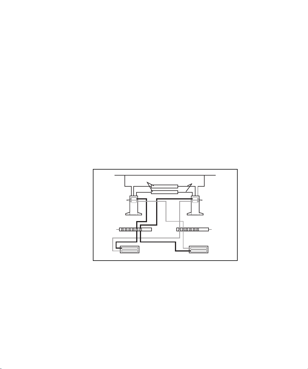
Figure 2-1 shows a two-node PDC/O2000 with a redundant Fibre Channel
Fabric that contains two fabrics, one for each Fibre Host Adapter per node.
The components and cable paths for the first fabric are shaded to distinguish
them from the components and cables for the second fabric.
Fibre Host
Adapters (2)
Node 1 Node 2
Fibre Channel
SAN Switch #1
RA4000/4100 Array #1
Figure 2-1. Two-node PDC/O2000 with a two-fabric redundant Fibre
Channel Fabric
RA4000/4100 Array #2
Fibre Host
Adapters (2)
Fibre Channel
SAN Switch #2
Used in conjunction with the I/O path failover capabilities of Secure Path
software, this redundant Fibre Channel Fabric configuration gives cluster
resources increased availability and fault tolerance.
Page 35

Multiple Redundant Fibre Channel Fabrics
The PDC/O2000 supports the use of multiple redundant Fibre Channel Fabrics
within the same cluster. You would install additional redundant Fibre Channel
Fabrics in a PDC/O2000 to:
■ Increase the amount of shared storage space available to the cluster’s
nodes. Each redundant Fibre Channel Fabric can connect to a finite
number of RA4000/RA4100 Arrays. These RA4000/RA4100 Arrays are
available only to the Fibre Host Adapters connected to that redundant
Fibre Channel Fabric.
■ Increase the cluster’s I/O performance.
Adding a second redundant Fibre Channel Fabric to the cluster involves
duplicating the hardware components used in the first redundant Fibre Channel
Fabric.
The maximum number of redundant Fibre Channel Fabrics you can install in a
PDC/O2000 cluster is restricted by the number of Fibre Host Adapters your
Compaq servers support. Refer to the Compaq server documentation for this
information.
Cluster Architecture 2-11
Page 36

2-12 Compaq Parallel Database Cluster Model PDC/O2000 for Oracle8i and Windows 2000 Administrator Guide
Figure 2-2 shows a two-node PDC/O2000 that contains two redundant Fibre
Channel Fabrics. In this example, each redundant Fibre Channel Fabric has its
own pair of Fibre Host Adapters in each node, a pair of Fibre Channel SAN
Switches, and two RA4000/RA4100 Arrays. In Figure 2-2, the hardware
components that constitute the second redundant Fibre Channel Fabric are
shaded.
Redundant
Fibre Channel
Fabric #1
Fibre Host
Adapters (4)
Fibre Channel
SAN Switch #1
RA4000/4100
Array #1
Fibre Channel
SAN Switch #1
Node 1 Node 2
RA4000/4100
Array #2
Fibre Channel
SAN Switch #2
Fibre Host
Adapters (4)
Fibre Channel
SAN Switch #2
Redundant
Fibre Channel
Fabric #2
RA4000/4100
Array #1
RA4000/4100
Array #2
Figure 2-2. Two-node PDC/O2000 with two redundant Fibre Channel Fabrics
Page 37

Maximum Distances Between Nodes and Shared Storage Components in a Redundant Fibre Channel Fabric
By using standard short-wave Fibre Channel cables with Gigabit Interface
Converter-Shortwave (GBIC-SW) modules, the following maximum distances
apply:
■ Each RA4000/RA4100 Array can be placed up to 500 meters from the
Fibre Channel SAN Switches to which it is cabled.
■ Each Fibre Channel SAN Switch can be placed up to 500 meters from
the Fibre Host Adapters to which it is cabled.
Figure 2-3 illustrates these maximum cable distances for a redundant Fibre
Channel Fabric.
500 meters
maximum
Fibre Host
Adapters (2)
Fibre Host
Adapters (2)
Cluster Architecture 2-13
Node 1
Fibre Channel
SAN Switch #1
500 meters
RA4000/4100 Array #1
Figure 2-3. Maximum distances between PDC/O2000 cluster nodes and
shared storage subsystem components in a redundant Fibre Channel Fabric
maximum
Node 2
Fibre Channel
SAN Switch #2
RA4000/4100 Array #2
Page 38

2-14 Compaq Parallel Database Cluster Model PDC/O2000 for Oracle8i and Windows 2000 Administrator Guide
I/O Data Paths in a Redundant Fibre Channel Fabric
A distinct I/O path connection exists between each Fibre Host Adapter in a
redundant Fibre Channel Fabric and every array controller port in each
RA4000/RA4100 Array in that redundant Fibre Channel Fabric.
Fibre Host Adapter-to-Fibre Channel SAN
Switch Paths
Figure 2-4 highlights the I/O data paths that run between the Fibre Host
Adapters and the Fibre Channel SAN Switches in a redundant Fibre Channel
Fabric.
Fibre Host
Adapters (2)
Fibre Channel
SAN Switch #1
Figure 2-4. Fibre Host Adapter-to-Fibre Channel SAN Switch data paths
Node 1 Node 2
RA4000/4100
Array #1
RA4000/4100
Array #2
Fibre Host
Adapters (2)
Fibre Channel
SAN Switch #2
Secure Path monitors the status of the components along each active path. If
Secure Path detects the failure of a Fibre Host Adapter, Fibre Channel cable,
or Fibre Channel SAN Switch along an active path, it automatically transfers
all I/O activity on that path to the components on the defined backup path.
Page 39

Cluster Architecture 2-15
Fibre Channel SAN Switch-to-Array
Controller Paths
Figure 2-5 highlights the I/O data paths that run between the Fibre Channel
SAN Switches and the two single-port RA4000 Array Controllers in each
RA4000/RA4100 Array.
Fibre Host
Adapters (2)
Node 1 Node 2
Fibre Channel
SAN Switch #1
RA4000/4100
Array #1
Figure 2-5. Fibre Channel SAN Switch-to-RA4100/4000 Array data paths
If any component along an active path fails, Secure Path detects the failure and
automatically transfers all I/O activity to the components on the defined
backup path.
I/O Path Configuration Guidelines for Redundant Fibre Channel Fabrics
You can use either of two I/O path configurations for every redundant FC-AL
in your PDC/O2000 cluster:
■ Active/standby configuration
Fibre Host
Adapters (2)
SAN Switch #2
RA4000/4100
Array #2
Fibre Channel
■ Active/active configuration
Page 40

2-16 Compaq Parallel Database Cluster Model PDC/O2000 for Oracle8i and Windows 2000 Administrator Guide
In every redundant Fibre Channel Fabric, at least two Fibre Host Adapters
must be installed in each node (one adapter for each Fibre Channel SAN
Switch in that redundant Fibre Channel Fabric).
In the active/standby configuration, only one of the two Fibre Host Adapters in
each node is active at any one time; the other Fibre Host Adapter is in the
standby state. The active Fibre Host Adapter is connected to the first Fibre
Channel SAN Switch, which is connected to the active array controller in each
RA4000/RA4100 Array. The standby Fibre Host Adapter is connected to the
second Fibre Channel SAN Switch, which is connected to the standby array
controller in each RA4000/RA4100 Array. The standby Fibre Host Adapter
remains in the standby state unless a failover from the active I/O path occurs.
In the active/standby configuration, the failure of any component along an
active I/O path (Fibre Host Adapter, Fibre Channel SAN Switch, active array
controller, or Fibre Channel cable) causes Secure Path to implement a
complete failover to the components on the standby I/O path.
In the active/active configuration, both Fibre Host Adapters in each node are
simultaneously active. Both are active because each Fibre Host Adapter is
connected to a Fibre Channel SAN Switch that, in turn, is connected to an
active array controller in each RA4000/RA4100 Array. Because each Fibre
Host Adapter and Fibre Channel SAN Switch must connect to at least one
active array controller, at least two RA4000/RA4100 Arrays must be present
in an active/active configuration.
See “Active/Standby Configuration Examples for Redundant Fibre Channel
Fabrics” in this chapter for a detailed description of active/standby
configuration examples with from one to five RA4000/RA4100 Arrays. See
“Active/Active Configuration Examples for Redundant Fibre Channel
Fabrics” for a detailed description of active/active configuration examples
when two to five RA4000/RA4100 Arrays are present.
Page 41

Cluster Architecture 2-17
Table 2-2 identifies the features of the active/standby and active/active
configurations for redundant Fibre Channel Fabrics.
Table 2-2
Features of Active/Standby and Active/Active Configurations for Redundant Fibre
Channel Fabrics
I/O Path Configuration Advantage Disadvantage
Active/standby with one
RA4000/RA4100 Array
Active/standby with two or more
RA4000/RA4100 Arrays
Active/standby is the only I/O
path configuration you can use
in a redundant Fibre Channel
Fabric that contains just one
RA4000/RA4100 Array.
Provides true cabling symmetry
between the Fibre Channel SAN
Switches and array controllers.
A Fibre Channel SAN Switch
connects to the same array
controller slot (top or bottom) in
every RA4000/RA4100 Array.
Load balancing between the two
Fibre Channel SAN Switches is
less than ideal because the
connection to the active array
controller in every
RA4000/RA4100 Array is routed
through the same Fibre Channel
SAN Switch. The second Fibre
Channel SAN Switch provides no
active I/O pathway unless an
active array controller or its
cable connection to the first
Fibre Channel SAN Switch fails.
continued
Page 42

2-18 Compaq Parallel Database Cluster Model PDC/O2000 for Oracle8i and Windows 2000 Administrator Guide
Table 2-2
Features of Active/Standby and Active/Active Configurations for Redundant Fibre Channel
Fabrics
continued
I/O Path Configuration Advantage Disadvantage
Active/active with two or more
RA4000/RA4100 Arrays
Provides a small but measurable
improvement in I/O performance
over the active/standby
configuration because both Fibre
Host Adapters in each node and
both Fibre Channel SAN
Switches are simultaneously
active. This improvement can be
meaningful for customers with
large cluster databases or high
I/O transaction requirements.
Provides better load balancing
between the two Storage Hubs
than the active/standby
configuration. Both Fibre
Channel SAN Switches are
connected to the same or
equivalent numbers of both
active and standby array
controllers in the
RA4000/RA4100 Arrays.
Does not provide true cabling
symmetry between Fibre
Channel SAN Switches and array
controllers if you consistently
configure the top or rightmost
array controller as the active
controller. Each Fibre Channel
SAN Switch is cabled to top
(active) array controllers in some
RA4000/RA4100 Arrays and
bottom (standby) controllers in
others. You can achieve cabling
symmetry if you configure the
bottom array controller in some
RA4000/RA4100 Arrays as
active. However, this requires
using Secure Path to configure
the lower array controller as
active if it is in standby mode.
Page 43

I/O Path Configuration Rules for Redundant Fibre Channel Fabrics
The following rules must be observed in I/O path configurations for
PDC/O2000 clusters with redundant Fibre Channel Fabrics:
■ Each redundant Fibre Channel Fabric must use either an active/standby
or active/active configuration. The active/standby or active/active
configuration is confined to that redundant Fibre Channel Fabric.
■ For each redundant Fibre Channel Fabric, at least two Fibre Host
Adapters are installed in each cluster node (one for each Fibre Channel
SAN Switch).
■ For each redundant Fibre Channel Fabric, at least two Fibre Channel
SAN Switches (Fibre Channel SAN Switch #1 and Fibre Channel SAN
Switch #2) are installed between the nodes and the RA4000/RA4100
Arrays.
■ A minimum of one RA4000/RA4100 Array is required for the
active/standby configuration.
■ A minimum of two RA4000/RA4100 Arrays is required for the
active/active configuration.
Cluster Architecture 2-19
■ Each RA4000/RA4100 Array must contain two array controllers to
provide redundant paths.
■ Only one of the two array controllers in an RA4000/RA4100 Array can
be active at a given time. The other array controller is the standby
controller.
■ I/O path hardware components must be connected using Fibre Channel
cables and GBIC-SW modules.
Page 44

2-20 Compaq Parallel Database Cluster Model PDC/O2000 for Oracle8i and Windows 2000 Administrator Guide
Active/Standby Configuration Examples for Redundant Fibre Channel Fabrics
This section describes examples of active/standby configurations when one,
two, three, four, and five RA4000/RA4100 Arrays are present in one
redundant Fibre Channel Fabric of a four-node PDC/O2000. These examples
represent one method for configuring active/standby configurations. They are
presented here to provide a relatively simple and consistent method for
building active/standby configurations for redundant Fibre Channel Fabrics.
IMPORTANT: Figures 2-6 through 2-10 show active/standby configurations for a
four-node cluster. Active/standby configurations for clusters with two, three, five, or more
nodes are not described here. However, the illustrated active/standby configuration
examples provided should supply sufficient information for building an active/standby
configuration in any PDC/O2000 cluster.
The active/standby configuration examples shown in Figures 2-6 through 2-10
follow these configuration guidelines:
■ For every Fibre Host Adapter pair, the top or leftmost Fibre Host
Adapter in each node is connected to the odd-numbered Fibre Channel
SAN Switch (Fibre Channel SAN Switch #1). This is the active Fibre
Host Adapter in the pair.
■ For every Fibre Host Adapter pair, the bottom or rightmost Fibre Host
Adapter in each node is connected to the even-numbered Fibre Channel
SAN Switch (Fibre Channel SAN Switch #2). This is the standby Fibre
Host Adapter in the pair.
■ In each RA4000/RA4100 Array, the top (rack model) or right rear
(tower model) array controller is always the active controller.
Page 45

Cluster Architecture 2-21
■ In each RA4000/RA4100 Array, the bottom (rack model) or left rear
(tower model) array controller is always the standby controller.
■ The odd-numbered Fibre Channel SAN Switch (Fibre Channel SAN
Switch #1) is connected to the active array controller in each
RA4000/RA4100 Array.
■ The even-numbered Fibre Channel SAN Switch (Fibre Channel SAN
Switch #2) is connected to the standby array controller in each
RA4000/RA4100 Array.
NOTE: The following active/standby configurations are examples only. You are not
required to follow these configurations.
For more information about installing active/standby configurations, refer to
the following sections in Chapter 5, “Installation and Configuration”:
■ “Cabling the Fibre Host Adapters to the Storage Hubs or Switches”
■ “Cabling the Storage Hubs or Switches to the RA4000 Array
Controllers”
In Figures 2-6 through 2-10, active I/O path components have been shaded to
distinguish them from standby (inactive) components. Black Fibre Channel
cables identify connections between active components; gray cables identify
connections between standby components.
Page 46
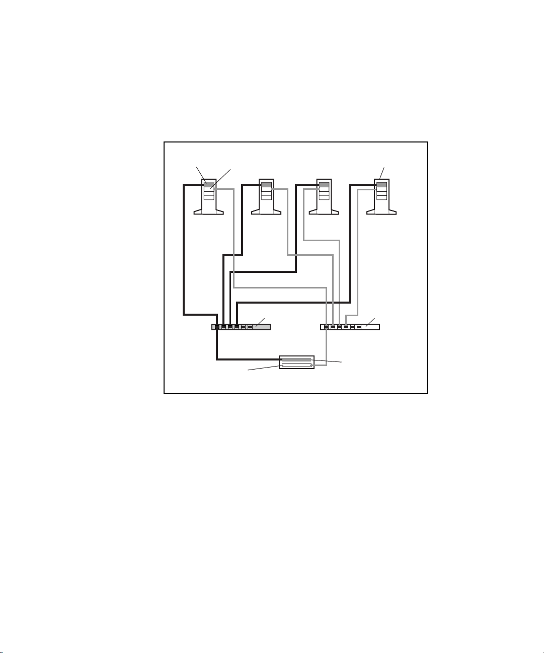
2-22 Compaq Parallel Database Cluster Model PDC/O2000 for Oracle8i and Windows 2000 Administrator Guide
Active/Standby Configuration with One RA4000/4100 Array
Figure 2-6 shows an active/standby I/O path configuration for a redundant
Fibre Channel Fabric in a four-node cluster with one RA4000/RA4100 Array.
Fibre Host
Adapter
(Active)
Node 1 Node 2 Node 3 Node 4
Fibre Host
Adapter
(Standby)
Standby
Array Controller
Fibre Channel
SAN Switch #1
RA4000/4100
Array #1
ProLiant
Servers (4)
Fibre Channel
SAN Switch #2
Active
Array Controller
Figure 2-6. Active/standby configuration with one RA4000/RA4100 Array
Page 47
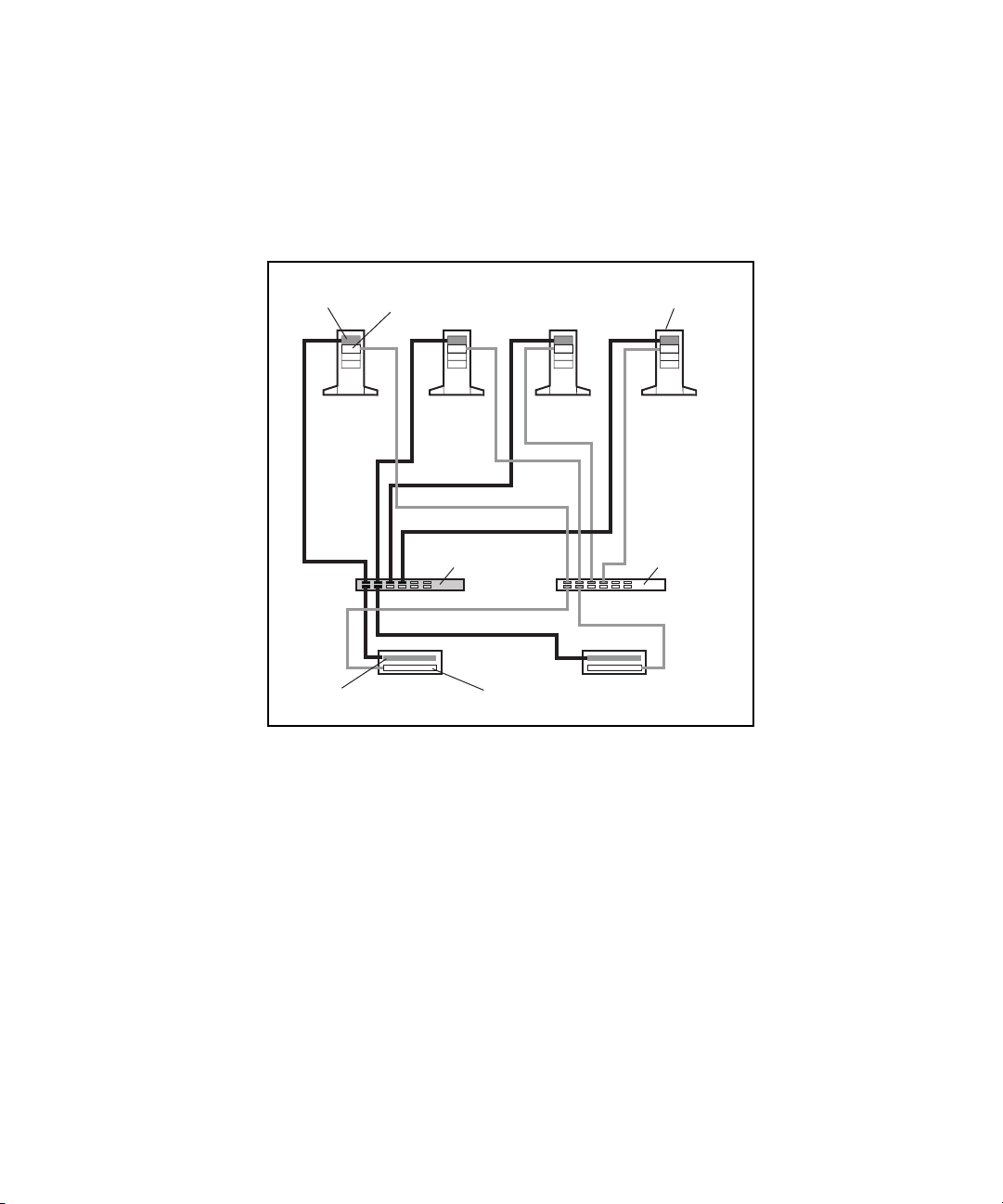
Cluster Architecture 2-23
Active/Standby Configuration with Two RA4000/4100 Arrays
Figure 2-7 shows an active/standby I/O path configuration for a redundant
Fibre Channel Fabric in a four-node cluster with two RA4000/RA4100 Arrays.
Fibre Host
Adapter
(Active)
Node 1 Node 2 Node 3 Node 4
Active
Array Controller
Fibre Host
Adapter
(Standby)
RA4000/4100
Array #1
Fibre Channel
SAN Switch #1
Standby
Array Controller
RA4000/4100
Array #2
ProLiant
Servers (4)
Fibre Channel
SAN Switch #2
Figure 2-7. Active/standby configuration with two RA4000/RA4100 Arrays
Page 48
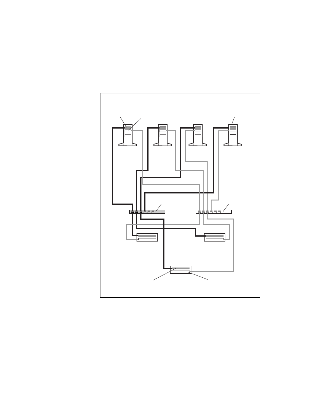
2-24 Compaq Parallel Database Cluster Model PDC/O2000 for Oracle8i and Windows 2000 Administrator Guide
Active/Standby Configuration with Three RA4000/RA4100 Arrays
Figure 2-8 shows an active/standby I/O path configuration for a redundant
Fibre Channel Fabric in a four-node cluster with three RA4000/RA4100
Arrays.
Fibre Host
Adapter
(Active)
Fibre Host
Adapter
(Standby)
Node 1 Node 2 Node 3 Node 4
Fibre Channel
SAN Switch #1
RA4000/4100
Array #1
Active
Array Controller
RA4000/4100
Array #3
RA4000/4100
Array #2
Standby
Array Controller
Servers (4)
Fibre Channel
SAN Switch #2
ProLiant
Figure 2-8. Active/standby configuration with three RA4000/RA4100 Arrays
Page 49

Cluster Architecture 2-25
Active/Standby Configuration with Four RA4000/RA4100 Arrays
Figure 2-9 shows an active/standby I/O path configuration for a redundant
Fibre Channel Fabric in a four-node cluster with four RA4000/RA4100
Arrays.
Fibre Host
Adapter
(Active)
Node 1 Node 2 Node 3 Node 4
Active
Array Controller
Fibre Host
Adapter
(Standby)
RA4000/4100
Array #1
RA4000/4100
Array #3
Fibre Channel
SAN Switch #1
Standby
Array Controller
RA4000/4100
Array #2
RA4000/4100
Array #4
ProLiant
Servers (4)
Fibre Channel
SAN Switch #2
Figure 2-9. Active/standby configuration with four RA4000/RA4100 Arrays
Page 50
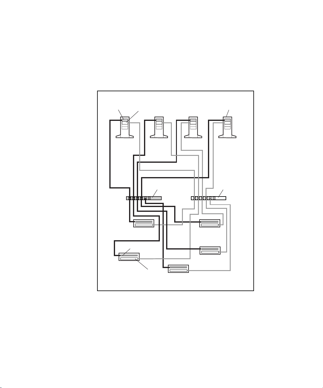
2-26 Compaq Parallel Database Cluster Model PDC/O2000 for Oracle8i and Windows 2000 Administrator Guide
Active/Standby Configuration with Five RA4000/RA4100 Arrays
Figure 2-10 shows an active/standby I/O path configuration for a redundant
Fibre Channel Fabric in a four-node cluster with five RA4000/RA4100
Arrays.
Fibre Host
Adapter
(Active)
Node 1 Node 2 Node 3 Node 4
RA4000/4100
Array #3
Fibre Host
Adapter
(Standby)
RA4000/4100
Array #1
Active
Array Controller
Standby
Array Controller
Fibre Channel
SAN Switch #1
RA4000/4100
Array #5
RA4000/4100
Array #2
RA4000/4100
Array #4
ProLiant
Servers (4)
Fibre Channel
SAN Switch #2
Figure 2-10. Active/standby configuration with five RA4000/RA4100 Arrays
Page 51

Active/Active Configuration Examples for Redundant Fibre Channel Fabrics
This section describes examples of active/active configurations when two,
three, four, and five RA4000/RA4100 Arrays are present in one redundant
Fibre Channel Fabric of a four-node PDC/O2000 cluster. These examples
represent one method for configuring active/active configurations. They are
presented here to provide a relatively simple and consistent method for
building active/active configurations for redundant Fibre Channel Fabrics.
IMPORTANT: Figures 2-11 through 2-14 show active/active configurations for a
four-node cluster. Active/active configurations for clusters with two, three, five, or more
nodes are not described here. However, the illustrated active/active configuration
examples provided should supply sufficient information for building an active/standby
configuration in any PDC/O2000 cluster.
The active/active configuration examples shown in Figures 2-11 through 2-14
follow these configuration guidelines:
■ For every Fibre Host Adapter pair, the top or leftmost Fibre Host
Adapter in each node is connected to the odd-numbered Fibre Channel
SAN Switch (Fibre Channel SAN Switch #1). This is an active Fibre
Host Adapter.
Cluster Architecture 2-27
■ For every Fibre Host Adapter pair, the bottom or rightmost Fibre Host
Adapter in each node is connected to the even-numbered Fibre Channel
SAN Switch (Fibre Channel SAN Switch #2). This is also an active
Fibre Host Adapter.
■ In each RA4000/RA4100 Array, the top (rack model) or right rear
(tower model) array controller is always the active controller.
■ In each RA4000/RA4100 Array, the bottom (rack model) or left rear
(tower model) array controller is always the standby controller.
■ The odd-numbered Fibre Channel SAN Switch (Fibre Channel SAN
Switch #1) is connected to the active array controller in each
odd-numbered RA4000/RA4100 Array (1, 3, and 5).
■ The odd-numbered Fibre Channel SAN Switch (Fibre Channel SAN
Switch #2) is connected to the standby array controller in each
even-numbered RA4000/RA4100 Array (2 and 4).
Page 52

2-28 Compaq Parallel Database Cluster Model PDC/O2000 for Oracle8i and Windows 2000 Administrator Guide
■
The even-numbered Fibre Channel SAN Switch (Fibre Channel SAN
Switch #2) is connected to the active array controller in each
even-numbered RA4000/RA4100 Array (2 and 4).
■ The even-numbered Fibre Channel SAN Switch is connected to the
standby array controller in each odd-numbered RA4000/RA4100 Array
(1, 3, and 5).
NOTE: The following active/active configurations are examples only. You are not required
to follow these configurations.
For more information about installing active/active configurations, refer to
these sections in Chapter 5, “Installation and Configuration”:
■ Cabling the Fibre Host Adapters to the Storage Hubs or Switches
■ Cabling the Storage Hubs or Switches to the RA4000 Array Controllers
In Figures 2-11 through 2-14, active I/O path components have been shaded to
distinguish them from standby (inactive) components. Black Fibre Channel
cables identify connections between active components; gray cables identify
connections between standby components.
Page 53

Cluster Architecture 2-29
Active/Active Configuration with Two RA4000/RA4100 Arrays
Figure 2-11 shows an active/active I/O path configuration for a redundant
Fibre Channel Fabric in a four-node cluster with two RA4000/RA4100 Arrays.
Fibre Host
Adapters (2)
Node 1 Node 2 Node 3 Node 4
Fibre Channel
SAN Switch #1
Active
Array Controller
RA4000/4100
Array #1
Standby
Array Controller
RA4000/4100
Array #2
ProLiant
Servers (4)
Fibre Channel
SAN Switch #2
Figure 2-11. Active/active configuration with two RA4000/RA4100 Arrays
Page 54

2-30 Compaq Parallel Database Cluster Model PDC/O2000 for Oracle8i and Windows 2000 Administrator Guide
Active/Active Configuration with Three RA4000/RA4100 Arrays
Figure 2-12 shows an active/active I/O path configuration for a redundant
Fibre Channel Fabric in a four-node cluster with three RA4000/RA4100
Arrays.
Fibre Host
Adapters (2)
Node 1 Node 2 Node 3 Node 4
Fibre Channel
SAN Switch #1
Active
Array Controller
RA4000/4100
Array #1
RA4000/4100
Array #3
Standby
Array Controller
RA4000/4100
ProLiant
Servers (4)
Fibre Channel
SAN Switch #2
Array #2
Figure 2-12. Active/active configuration with three RA4000/RA4100 Arrays
Page 55
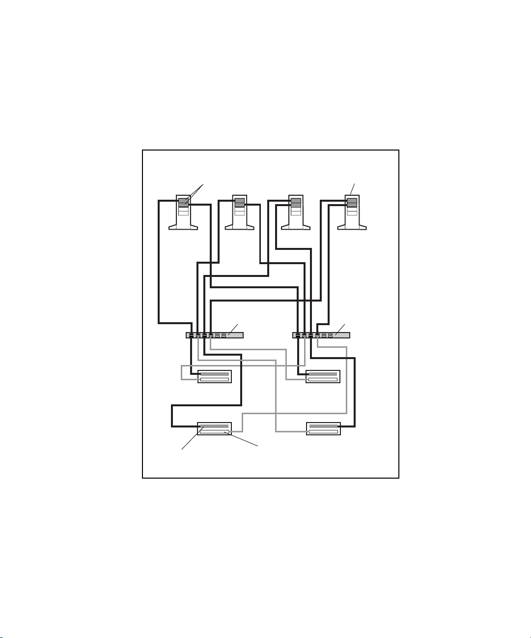
Cluster Architecture 2-31
Active/Active Configuration with Four RA4000/RA4100 Arrays
Figure 2-13 shows an active/active I/O path configuration for a redundant
Fibre Channel Fabric in a four-node cluster with four RA4000/RA4100
Arrays.
Fibre Host
Adapters (2)
Node 1 Node 2 Node 3 Node 4
Fibre Channel
SAN Switch #1
Active
Array Controller
RA4000/4100
Array #1
RA4000/4100
Array #3
Standby
Array Controller
RA4000/4100
RA4000/4100
ProLiant
Servers (4)
Fibre Channel
SAN Switch #2
Array #2
Array #4
Figure 2-13. Active/active configuration with four RA4000/RA4100 Arrays
Page 56

2-32 Compaq Parallel Database Cluster Model PDC/O2000 for Oracle8i and Windows 2000 Administrator Guide
Active/Active Configuration with Five RA4000/RA4100 Arrays
Figure 2-14 shows an active/active I/O path configuration for a redundant
Fibre Channel Fabric in a four-node cluster with five RA4000/RA4100
Arrays.
Adapters (2)
Node 1 Node 2 Node 3 Node 4
Active
Array Controller
Fibre Host
RA4000/4100
Array #1
RA4000/4100
Array #3
Fibre Channel
SAN Switch #1
Standby
Array Controller
RA4000/4100
Array #5
RA4000/4100
Array #2
RA4000/4100
Array #4
ProLiant
Servers (4)
Fibre Channel
SAN Switch #2
Figure 2-14. Active/active configuration with five RA4000/RA4100 Arrays
Page 57

Cluster Architecture 2-33
Summary of I/O Path Failure and Failover Scenarios for Redundant Fibre Channel Fabrics
Table 2-3 identifies possible I/O path failure events in redundant Fibre
Channel Fabrics for active/standby configurations with one RA4000/RA4100
Array and the failover response, if any, implemented by Secure Path for each
failure.
Table 2-3
I/O Path Failure and Failover Scenarios in Redundant Fibre Channel Fabrics for
Active/Standby Configurations With One RA4000/RA4100 Array
Description of Failure Failover Response
The active array controller in the
RA4000/RA4100 Array fails.
The standby array controller in the
RA4000/RA4100 Array fails.
The Fibre Channel cable
connection between the active
array controller and its Fibre
Channel SAN Switch is broken.
The Fibre Channel cable
connection between the standby
array controller and its Fibre
Channel SAN Switch is broken.
The Fibre Channel SAN Switch
connected to the active array
controller fails.
Secure Path forces a complete failover to the standby I/O path
components, including the standby Fibre Host Adapter in each
node, the other Fibre Channel SAN Switch, the standby array
controller in the RA4000/RA4100 Array, and Fibre Channel cables.
None
Secure Path forces a complete failover to the standby I/O path
components, including the standby Fibre Host Adapter in each
node, the other Fibre Channel SAN Switch, the standby array
controller in the RA4000/RA4100 Array, and Fibre Channel cables.
None
Secure Path forces a complete failover to the standby I/O path
components, including the standby Fibre Host Adapter in each
node, the other Fibre Channel SAN Switch, the standby array
controller in the RA4000/RA4100 Array, and Fibre Channel cables.
continued
Page 58

2-34 Compaq Parallel Database Cluster Model PDC/O2000 for Oracle8i and Windows 2000 Administrator Guide
Table 2-3
I/O Path Failure and Failover Scenarios in Redundant Fibre Channel Fabrics for
Active/Standby Configurations With One RA4000/RA4100 Array
Description of Failure Failover Response
continued
The Fibre Channel SAN Switch
connected to the standby array
controller fails.
The Fibre Channel cable
connection between a Fibre Host
Adapter and the Fibre Channel
SAN Switch connected to the
active array controller is broken.
The Fibre Channel cable
connection between a Fibre Host
Adapter and the Fibre Channel
SAN Switch connected to the
standby array controller is broken.
A Fibre Host Adapter connected to
the Fibre Channel SAN Switch that
connects to the active array
controller fails.
A Fibre Host Adapter connected to
the Fibre Channel SAN Switch that
connects to the standby array
controller fails.
None
Secure Path forces a complete failover to the standby I/O path
components, including the standby Fibre Host Adapter in each
node, the other Fibre Channel SAN Switch, the standby array
controller in the RA4000/RA4100 Array, and Fibre Channel cables.
None
Secure Path forces a complete failover to the standby I/O path
components, including the standby Fibre Host Adapter in each
node, the other Fibre Channel SAN Switch, the standby array
controller in the RA4000/RA4100 Array, and Fibre Channel cables.
None
Page 59

Cluster Architecture 2-35
Table 2-4 identifies possible I/O path failure events for active/standby
configurations in redundant Fibre Channel Fabrics with two or more
RA4000/RA4100 Arrays and the failover response, if any, implemented by
Secure Path for each failure.
Table 2-4
I/O Path Failure and Failover Scenarios in Redundant Fibre Channel Fabrics for
Active/Standby Configurations With Two or More RA4000/RA4100 Arrays
Description of Failure Failover Response
The active array controller in one
RA4000/RA4100 Array fails.
The standby array controller in one
RA4000/RA4100 Array fails.
The Fibre Channel cable
connection between the active
array controller in one
RA4000/RA4100 Array and its
Fibre Channel SAN Switch is
broken.
Secure Path forces a complete failover to the standby I/O path
components, including the standby Fibre Host Adapter in each
node, the other Fibre Channel SAN Switch, the standby array
controller in each RA4000/RA4100 Array, and Fibre Channel cables.
None
Secure Path forces a complete failover to the standby I/O path
components, including the standby Fibre Host Adapter in each
node, the other Fibre Channel SAN Switch, the standby array
controller in each RA4000/RA4100 Array, and Fibre Channel cables.
continued
Page 60

2-36 Compaq Parallel Database Cluster Model PDC/O2000 for Oracle8i and Windows 2000 Administrator Guide
Table 2-4
I/O Path Failure and Failover Scenarios in Redundant Fibre Channel Fabrics for
Active/Standby Configurations With Two or More RA4000/RA4100 Arrays
Description of Failure Failover Response
continued
The Fibre Channel cable
connection between the standby
array controller in one
RA4000/RA4100 Array and its
Fibre Channel SAN Switch is
broken.
The Fibre Channel SAN Switch
that is connected to the active
array controller in each
RA4000/RA4100 Array fails.
The Fibre Channel SAN Switch
that is connected to the standby
array controller in each
RA4000/RA4100 Array fails.
The Fibre Channel cable
connection between the Fibre
Channel SAN Switch that is
connected to the active array
controllers and a Fibre Host
Adapter is broken.
The Fibre Channel cable
connection between the Fibre
Channel SAN Switch that is
connected to the standby array
controllers and a Fibre Host
Adapter is broken.
None
Secure Path forces a complete failover to the standby I/O path
components, including the standby Fibre Host Adapter in each
node, the other Fibre Channel SAN Switch, the standby array
controller in each RA4000/RA4100 Array, and Fibre Channel cables.
None
Secure Path forces a complete failover to the standby I/O path
components, including the standby Fibre Host Adapter in each
node, the other Fibre Channel SAN Switch, the standby array
controller in the each RA4000/RA4100 Array, and Fibre Channel
cables.
None
A Fibre Host Adapter connected to
the Fibre Channel SAN Switch that
is connected to the active array
controllers fails.
A Fibre Host Adapter connected to
the Fibre Channel SAN Switch that
is connected to the standby array
controllers fails.
Secure Path forces a complete failover to the standby I/O path
components, including the standby Fibre Host Adapter in each
node, the other Fibre Channel SAN Switch, the standby array
controller in each RA4000/RA4100 Array, and Fibre Channel cables.
None
Page 61

Cluster Architecture 2-37
Table 2-5 identifies possible I/O path failure events in redundant Fibre
Channel Fabrics for active/active configurations with two or more
RA4000/RA4100 Arrays and the failover response, if any, implemented by
Secure Path for each failure.
Table 2-5
I/O Path Failure and Failover Scenarios in Redundant Fibre Channel Fabrics for
Active/Active Configurations With Two or More RA4000/RA4100 Arrays
Description of Failure Failover Response
The active array controller in one
RA4000/RA4100 Array fails.
The standby array controller in one
RA4000/RA4100 Array fails.
The Fibre Channel cable
connection between the active
array controller in one
RA4000/RA4100 Array and its
Fibre Channel SAN Switch is
broken.
Secure Path makes the standby array controller in the
RA4000/RA4100 Array active and reroutes I/O activity to that array
controller. The Fibre Channel SAN Switch that is connected to the
new active array controller becomes the active I/O path to this
RA4000/RA4100 Array. In each node, I/O activity between the Fibre
Host Adapter that is connected to the failed array controller is
rerouted to the second Fibre Host Adapter in the pair, but only along
the I/O path to the affected RA4000/RA4100 Array. The first Fibre
Host Adapter in each node continues to be the active I/O path for
active array controllers in other RA4000/RA4100 Arrays to which it
is connected.
None
Secure Path makes the active array controller to which the failed
cable is connected inactive. The standby array controller in the
RA4000/RA4100 Array becomes active. I/O activity is routed
through the Fibre Channel cable installed to the new active array
controller and the other Fibre Channel SAN Switch. In each node,
I/O activity between the Fibre Host Adapter that is connected to the
failed array controller is rerouted to the second Fibre Host Adapter
in the pair, but only along the I/O path to the affected
RA4000/RA4100 Array. The first Fibre Host Adapter in each node
continues to be the active I/O path for active array controllers in
other RA4000/RA4100 Arrays to which it is connected.
continued
Page 62

2-38 Compaq Parallel Database Cluster Model PDC/O2000 for Oracle8i and Windows 2000 Administrator Guide
Table 2-5
I/O Path Failure and Failover Scenarios in Redundant Fibre Channel Fabrics for Active/Active
Configurations With Two or More RA4000/RA4100 Arrays
Description of Failure Failover Response
continued
The Fibre Channel cable
connection between the standby
array controller in one
RA4000/RA4100 Array and its
Fibre Channel SAN Switch is
broken.
A Fibre Channel SAN Switch fails. Secure Path makes each active array controller to which the failed
The Fibre Channel cable
connection between a Fibre
Channel SAN Switch and a Fibre
Host Adapter in one node is
broken.
A Fibre Host Adapter in a node
fails.
None
Fibre Channel SAN Switch is connected inactive. The standby array
controller in each affected RA4000/RA4100 Array becomes the
active array controller. The Fibre Channel SAN Switch that is
connected to the new active array controllers becomes the active
I/O path for these RA4000/RA4100 Arrays. In each node, the Fibre
Host Adapter that is connected to the failed Fibre Channel SAN
Switch becomes inactive, and all I/O activity is rerouted through the
other Fibre Host Adapter in the pair and the remaining active Fibre
Channel SAN Switch.
Secure Path makes all I/O path connections between the affected
Fibre Host Adapter and active array controllers inactive. The
standby array controller in every affected RA4000/RA4100 Array
becomes the active array controller. The Fibre Channel SAN Switch
connected to the newly active array controllers becomes the active
I/O path for the entire FC-AL. The Fibre Channel SAN Switch
connected to the failed Fibre Channel cable becomes inactive. The
second Fibre Host Adapter in each node, which is connected to the
only active Fibre Channel SAN Switch, becomes the only active
Fibre Host Adapter in the node’s pair.
Secure Path makes all I/O path connections between the affected
Fibre Host Adapter and active array controllers inactive. The
standby array controller in every affected RA4000/RA4100 Array
becomes the active array controller. The Fibre Channel SAN Switch
connected to the newly active array controllers becomes the active
I/O path for the entire FC-AL. The Fibre Channel SAN Switch
connected to the failed Fibre Host Adapter becomes inactive. The
second Fibre Host Adapter in each node, which is connected to the
only active Fibre Channel SAN Switch, becomes the only active
Fibre Host Adapter in the node’s pair.
Page 63

I/O Path Configurations for Redundant Fibre Channel Arbitrated Loops
Overview of FC-AL SAN Topology
Fibre Channel standards define a multi-layered architecture for moving data
across the storage area network (SAN). This layered architecture can be
implemented using the Fibre Channel Fabric or the Fibre Channel Arbitrated
Loop (FC-AL) topology. The PDC/O2000 supports both topologies.
A redundant FC-AL is two to four FC-AL Switches or Storage Hubs installed
between Fibre Host Adapters in a PDC/O2000’s cluster nodes and the array
controllers in the shared storage subsystems. These hardware components
cannot be shared by other redundant FC-ALs or redundant Fibre Channel
Fabrics in the same cluster.
When Storage Hubs are used, the FC-AL SAN is a shared gigabit transport
with a total 100 MBps bandwidth divided among all Storage Hub ports. The
functional bandwidth available to any one device on a Storage Hub port is
determined by the total population on the segment and the level of activity of
devices on other ports. The more devices used, the less bandwidth that is
available for each port.
Cluster Architecture 2-39
When FC-AL Switches are used, the FC-AL SAN supports multiple
100 MB/sec point-to-point connections in parallel. Each FC-AL Switch
provides multiple dedicated, non-blocking connections between Fibre Host
Adapters and array controllers (as contrasted with the shared connections on a
Storage Hub). The FC-AL Switch also eliminates the shared bandwidth speed
limitations of the Storage Hub.
Page 64

2-40 Compaq Parallel Database Cluster Model PDC/O2000 for Oracle8i and Windows 2000 Administrator Guide
Redundant Fibre Channel Arbitrated Loops
A redundant FC-AL refers to the redundant hardware implemented to connect
Fibre Host Adapters to a particular set of shared storage devices in a
PDC/O2000. Each redundant FC-AL consists of the following hardware:
■ Two or more Fibre Host Adapters in each node
■ Two or more Storage Hubs or FC-AL Switches
■ One or more RA4000/RA4100 Arrays, each containing two single-port
RA4000 Array Controllers
■ GBIC-SW modules installed in Fibre Host Adapters, Storage Hubs or
FC-AL Switches, and array controllers to connect Fibre Channel cables
■ Fibre Channel cables used to connect the Fibre Host Adapters to the
Storage Hubs or FC-AL Switches to the array controllers
IMPORTANT: For detailed information about cascading two FC-AL Switches, refer to the
latest Compaq StorageWorks documentation. This guide does not document cascaded
configurations for the FC-AL Switch.
A redundant FC-AL consists of from two to four individual loops, each of
which traverses a single Storage Hub or FC-AL Switch. The number of loops
present is determined by the number of Fibre Host Adapters per node that are
dedicated to the redundant FC-AL: two Fibre Host Adapters per node create
two loops; four Fibre Host Adapters per node create four loops.
Page 65

Cluster Architecture 2-41
Figure 2-15 shows a two-node PDC/O2000 with a redundant FC-AL that
contains two loops, one for each Fibre Host Adapter per node. The
components and cable paths for the first loop are shaded to distinguish them
from the components for the other loop.
Fibre Host
Adapters (2)
Node 1 Node 2
FC-AL Switch/Storage
Hub #1
RA4000/4100 Array #1
RA4000/4100 Array #2
Fibre Host
Adapters (2)
FC-AL Switch/Storage
Hub #2
Figure 2-15. Two-node PDC/O2000 with a two-loop redundant Fibre
Channel Arbitrated Loop
Used in conjunction with the I/O path failover capabilities of Secure Path
software, this redundant FC-AL configuration gives cluster resources
increased availability and fault tolerance.
Page 66

2-42 Compaq Parallel Database Cluster Model PDC/O2000 for Oracle8i and Windows 2000 Administrator Guide
Multiple Redundant Fibre Channel Arbitrated Loops
The PDC/O2000 supports the use of multiple redundant FC-ALs within the
same cluster. You would install additional redundant FC-ALs in a
PDC/O2000 to:
■ Increase the amount of shared storage space available to the cluster’s
nodes. Each redundant FC-AL can connect to a finite number of
RA4000/RA4100 Arrays. These RA4000/RA4100 Arrays are available
only to the Fibre Host Adapters connected to that redundant FC-AL.
■ Increase the cluster’s I/O performance.
Adding a second redundant FC-AL to the cluster involves duplicating the
hardware components used in the first redundant FC-AL.
The maximum number of redundant FC-ALs you can install in a PDC/O2000
cluster is restricted by the number of Fibre Host Adapters your Compaq
servers support. Refer to the Compaq server documentation for this
information.
Page 67

Cluster Architecture 2-43
Figure 2-16 shows a two-node PDC/O2000 that contains two redundant
FC-ALs. In this example, each redundant FC-AL has its own pair of Fibre
Host Adapters in each node, a pair of Storage Hubs or FC-AL Switches, and
two RA4000/RA4100 Arrays. In Figure 2-2, the hardware components that
constitute the second redundant FC-AL are shaded.
Redundant
FC-AL #1
Fibre Host
Adapters (4)
RA4000/4100
Array #1
FC-AL
Switch/Storage
Hub #1
Node 1 Node 2
FC-AL
Switch/Storage
Hub #1
RA4000/4100
Array #2
FC-AL
Switch/Storage
Hub #2
Fibre Host
Adapters (4)
FC-AL
Switch/Storage
Hub #2
Redundant
FC-AL #2
RA4000/4100
Array #1
RA4000/4100
Array #2
Figure 2-16. Two-node PDC/O2000 with two redundant Fibre Channel
Arbitrated Loops
Page 68

2-44 Compaq Parallel Database Cluster Model PDC/O2000 for Oracle8i and Windows 2000 Administrator Guide
Maximum Distances Between Nodes and Shared
Storage Components in a Redundant FC-AL
By using standard short-wave Fibre Channel cables with Gigabit Interface
Converter-Shortwave (GBIC-SW) modules, the following maximum distances
apply:
■ Each RA4000/RA4100 Array can be placed up to 500 meters from the
Storage Hubs or FC-AL Switches to which it is cabled.
■ Each Storage Hub or FC-AL Switch can be placed up to 500 meters
from the Fibre Host Adapters to which it is cabled.
Figure 2-17 illustrates these maximum cable distances for a redundant FC-AL.
500 meters
maximum
Fibre Host
Adapters (2)
Fibre Host
Adapters (2)
FC-AL
Switch/Storage
Hub #1
RA4000/4100 Array #1
Node 1
500 meters
maximum
Node 2
RA4000/4100 Array #2
FC-AL
Switch/Storage
Hub #2
Figure 2-17. Maximum distances between PDC/O2000 cluster nodes and
shared storage subsystem components in a redundant FC-AL
Page 69

I/O Data Paths in a Redundant FC-AL
A distinct I/O path connection exists between each Fibre Host Adapter in a
cluster node and every array controller port in each RA4000/RA4100 Array in
the redundant FC-AL.
Fibre Host Adapter-to-Storage Hub/Switch
Paths
Figure 2-18 highlights the I/O data paths that run between the Fibre Host
Adapters and the Storage Hubs or FC-AL Switches in a redundant FC-AL.
Cluster Architecture 2-45
Fibre Host
Adapters (2)
FC-AL
Switch/Storage
Hub #1
Figure 2-18. Fibre Host Adapter-to-FC-AL Switch/Storage Hub data paths
Node 1 Node 2
RA4000/4100
Array #1
RA4000/4100
Array #2
Fibre Host
Adapters (2)
FC-AL
Switch/Storage
Hub #2
Secure Path monitors the status of the components along each active path. If
Secure Path detects the failure of a Fibre Host Adapter, Fibre Channel cable,
Storage Hub, or FC-AL Switch along an active path, it automatically transfers
all I/O activity on that path to the components on the defined backup path.
Page 70

2-46 Compaq Parallel Database Cluster Model PDC/O2000 for Oracle8i and Windows 2000 Administrator Guide
Storage Hub/Switch-to-Array Controller Paths
Figure 2-19 highlights the I/O data paths that run between the Storage Hubs or
FC-AL Switches and the two single-port RA4000 Array Controllers in each
RA4000/RA4100 Array.
Fibre Host
Adapters (2)
FC-AL
Switch/Storage
Hub #1
Node 1 Node 2
RA4000/4100
Array #1
RA4000/4100
Array #2
Fibre Host
Adapters (2)
FC-AL
Switch/Storage
Hub #2
Figure 2-19. FC-AL Switch/Storage Hub-to-RA4000/RA4100 Array data paths
If any component along an active path fails, Secure Path detects the failure and
automatically transfers all I/O activity to the components on the defined
backup path.
Page 71

I/O Path Configuration Guidelines for Redundant Fibre Channel Arbitrated Loops
You can use either of two I/O path configurations for every redundant FC-AL
in your PDC/O2000 cluster:
■ Active/standby configuration
■ Active/active configuration
In every redundant FC-AL, at least two Fibre Host Adapters must be installed
in each node (one Fibre Host Adapter for each Storage Hub or FC-AL Switch
in that redundant FC-AL).
In the active/standby configuration, only one of the two Fibre Host Adapters in
each node is active at any one time; the other Fibre Host Adapter is in the
standby state. The active Fibre Host Adapter is connected to the first Storage
Hub or FC-AL Switch, which is connected to the active array controller in
each RA4000/RA4100 Array. The standby Fibre Host Adapter is connected to
the second Storage Hub or FC-AL Switch, which is connected to the standby
array controller in each RA4000/RA4100 Array. The standby Fibre Host
Adapter remains in the standby state unless a failover from the active I/O path
occurs. In the active/standby configuration, the failure of any component along
an active I/O path (Fibre Host Adapter, Storage Hub or FC-AL Switch, active
array controller, or Fibre Channel cable) causes Secure Path to implement a
complete failover to the components on the standby I/O path.
Cluster Architecture 2-47
In the active/active configuration, both Fibre Host Adapters in each node are
simultaneously active. Both are active because each Fibre Host Adapter is
connected to a Storage Hub or FC-AL Switch that, in turn, is connected to an
active array controller in each RA4000/RA4100 Array. Because each Fibre
Host Adapter and Storage Hub or FC-AL Switch must connect to at least one
active array controller, at least two RA4000/RA4100 Arrays must be present
in an active/active configuration.
Page 72

2-48 Compaq Parallel Database Cluster Model PDC/O2000 for Oracle8i and Windows 2000 Administrator Guide
See “Active/Standby Configuration Examples for Redundant FC-ALs” in this
chapter for a detailed description of active/standby configuration examples for
a redundant FC-AL with from one to five RA4000/RA4100 Arrays. See
“Active/Active Configuration Examples for Redundant FC-ALs” for a detailed
description of active/active configuration examples when two to five
RA4000/RA4100 Arrays are present.
Table 2-6 identifies the features of the active/standby and active/active
configurations for redundant FC-ALs.
Table 2-6
Features of Active/Standby and Active/Active Configurations for Redundant Fibre
Channel Arbitrated Loops
I/O Path Configuration Advantage Disadvantage
Active/standby with one
RA4000/RA4100 Array
Active/standby with two or more
RA4000/RA4100 Arrays
Active/standby is the only I/O
path configuration you can use
in a redundant FC-AL that
contains just one
RA4000/RA4100 Array.
Provides true cabling symmetry
between the Storage Hubs or
FC-AL Switches and array
controllers. A Storage Hub or
FC-AL Switch connects to the
same array controller slot (top or
bottom) in every
RA4000/RA4100 Array.
Load balancing between the two
Storage Hubs or FC-AL Switches
is less than ideal because the
connection to the active array
controller in every
RA4000/RA4100 Array is routed
through the same Storage Hub
or FC-AL Switch. The second
Storage Hub or FC-AL Switch
provides no active I/O pathway
unless an active array controller
or its cable connection to the
first Storage Hub or FC-AL
Switch fails.
continued
Page 73

Cluster Architecture 2-49
Table 2-6
Features of Active/Standby and Active/Active Configurations for Redundant Fibre Channel
Arbitrated Loops
I/O Path Configuration Advantage Disadvantage
continued
Active/active with two or more
RA4000/RA4100 Arrays
Provides a small but measurable
improvement in I/O performance
over the active/standby
configuration because both Fibre
Host Adapters in each node and
both Storage Hubs or FC-AL
Switches are simultaneously
active. This improvement can be
meaningful for customers with
large cluster databases or high
I/O transaction requirements.
Provides better load balancing
between the two Storage Hubs
than the active/standby
configuration. Both Storage
Hubs or FC-AL Switches are
connected to the same or
equivalent numbers of both
active and standby array
controllers in the
RA4000/RA4100 Arrays.
Does not provide true cabling
symmetry between Storage
Hubs or FC-AL Switches and
array controllers if you
consistently configure the top or
rightmost array controller as the
active controller. Each Storage
Hub or FC-AL Switch is cabled
to top (active) array controllers
in some RA4000/RA4100 Arrays
and bottom (standby) controllers
in others. You can achieve
cabling symmetry if you
configure the bottom array
controller in some
RA4000/RA4100 Arrays as
active. However, this requires
using Secure Path to configure
the lower array controller as
active if it is in standby mode.
Page 74

2-50 Compaq Parallel Database Cluster Model PDC/O2000 for Oracle8i and Windows 2000 Administrator Guide
I/O Path Configuration Rules for Redundant FC-ALs
The following rules must be observed in I/O path configurations for
PDC/O2000 clusters with redundant FC-ALs:
■ Each redundant FC-AL must use either an active/standby or
active/active configuration. The active/standby or active/active
configuration is confined to that redundant FC-AL.
■ For each redundant FC-AL, at least two Fibre Host Adapters are
installed in each cluster node (one for each Storage Hub or FC-AL
Switch).
■ For each redundant FC-AL, at least two Storage Hubs or FC-AL
Switches (Storage Hub/FC-AL Switch #1 and Storage Hub/FC-AL
Switch #2) are installed between the nodes and the RA4000/RA4100
Arrays.
■ A minimum of one RA4000/RA4100 Array is required for the
active/standby configuration.
■ A minimum of two RA4000/RA4100 Arrays is required for the
active/active configuration.
■ Each RA4000/RA4100 Array must contain two array controllers to
provide redundant paths.
■ Only one of the two array controllers in an RA4000/RA4100 Array can
be active at a given time. The other array controller is the standby
controller.
■ I/O path hardware components must be connected using Fibre Channel
cables and GBIC-SW modules.
Page 75

Active/Standby Configuration Examples for
Redundant FC-ALs
This section describes examples of active/standby configurations when one,
two, three, four, and five RA4000/RA4100 Arrays are present in one
redundant FC-AL of a four-node PDC/O2000. These examples represent one
method for configuring active/standby configurations. They are presented here
to provide a relatively simple and consistent method for building
active/standby configurations.
IMPORTANT: Figures 2-20 through 2-24 show active/standby configurations for a
four-node cluster. Active/standby configurations for clusters with two, three, five, or more
nodes are not described here. However, the illustrated active/standby configuration
examples provided should supply sufficient information for building an active/standby
configuration in any PDC/O2000 cluster.
The active/standby configuration examples shown in Figures 2-20 through
2-24 follow these configuration guidelines:
■ For every Fibre Host Adapter pair, the top or leftmost Fibre Host
Adapter in each node is connected to the odd-numbered Storage Hub or
FC-AL Switch (Storage Hub/FC-AL Switch #1). This is the active Fibre
Host Adapter in the pair.
Cluster Architecture 2-51
■ For every Fibre Host Adapter pair, the bottom or rightmost Fibre Host
Adapter in each node is connected to the even-numbered Storage Hub or
FC-AL Switch (Storage Hub/FC-AL Switch #2). This is the standby
Fibre Host Adapter in the pair.
■ In each RA4000/RA4100 Array, the top (rack model) or right rear
(tower model) array controller is always the active controller.
Page 76

2-52 Compaq Parallel Database Cluster Model PDC/O2000 for Oracle8i and Windows 2000 Administrator Guide
■
In each RA4000/RA4100 Array, the bottom (rack model) or left rear
(tower model) array controller is always the standby controller.
■ The odd-numbered Storage Hub or FC-AL Switch (Storage Hub/FC-AL
Switch #1) is connected to the active array controller in each
RA4000/RA4100 Array.
■ The even-numbered Storage Hub or FC-AL Switch (Storage
Hub/FC-AL Switch #2) is connected to the standby array controller in
each RA4000/RA4100 Array.
NOTE: The following active/standby configurations are examples only. You are not
required to follow these configurations.
For more information about installing active/standby configurations, refer to
the following sections in Chapter 5, “Installation and Configuration”:
■ “Cabling the Fibre Host Adapters to the Storage Hubs or Switches”
■ “Cabling the Storage Hubs or Switches to the RA4000 Array
Controllers”
In Figures 2-20 through 2-24, active I/O path components have been shaded to
distinguish them from standby (inactive) components. Black Fibre Channel
cables identify connections between active components; gray cables identify
connections between standby components.
Page 77

Cluster Architecture 2-53
Active/Standby Configuration with One RA4000/4100 Array
Figure 2-20 shows an active/standby I/O path configuration for a redundant
FC-AL in a four-node cluster with one RA4000/RA4100 Array.
Fibre Host
Adapter
(Active)
Node 1 Node 2 Node 3 Node 4
Fibre Host
Adapter
(Standby)
Standby
Array Controller
FC-AL
Switch/Storage
Hub #1
RA4000/4100
Array #1
ProLiant
Servers (4)
FC-AL
Switch/Storage
Hub #2
Active
Array Controller
Figure 2-20. Active/standby configuration with one RA4000/RA4100 Array
Page 78

2-54 Compaq Parallel Database Cluster Model PDC/O2000 for Oracle8i and Windows 2000 Administrator Guide
Active/Standby Configuration with Two RA4000/4100 Arrays
Figure 2-21 shows an active/standby I/O path configuration for a redundant
FC-AL in a four-node cluster with two RA4000/RA4100 Arrays.
Fibre Host
Adapter
(Active)
Node 1 Node 2 Node 3 Node 4
Active
Array Controller
Fibre Host
Adapter
(Standby)
RA4000/4100
Array #1
FC-AL
Switch/Storage
Hub #1
Standby
Array Controller
RA4000/4100
Array #2
ProLiant
Servers (4)
FC-AL
Switch/Storage
Hub #2
Figure 2-21. Active/standby configuration with two RA4000/RA4100 Arrays
Page 79

Cluster Architecture 2-55
Active/Standby Configuration with Three RA4000/RA4100 Arrays
Figure 2-22 shows an active/standby I/O path configuration for a redundant
FC-AL in a four-node cluster with three RA4000/RA4100 Arrays.
Fibre Host
Adapter
(Active)
Node 1 Node 2 Node 3 Node 4
Fibre Host
Adapter
(Standby)
RA4000/4100
Array #1
Active
Array Controller
FC-AL
Switch/Storage
Hub #1
RA4000/4100
Array #3
RA4000/4100
Array #2
Standby
Array Controller
ProLiant
Servers (4)
FC-AL
Switch/Storage
Hub #2
Figure 2-22. Active/standby configuration with three RA4000/RA4100 Arrays
Page 80

2-56 Compaq Parallel Database Cluster Model PDC/O2000 for Oracle8i and Windows 2000 Administrator Guide
Active/Standby Configuration with Four RA4000/RA4100 Arrays
Figure 2-23 shows an active/standby I/O path configuration for a redundant
FC-AL in a four-node cluster with four RA4000/RA4100 Arrays.
Fibre Host
Adapter
(Active)
Node 1 Node 2 Node 3 Node 4
Active
Array Controller
Fibre Host
Adapter
(Standby)
RA4000/4100
Array #1
RA4000/4100
Array #3
FC-AL
Switch/Storage
Hub #1
Standby
Array Controller
RA4000/4100
Array #2
RA4000/4100
Array #4
ProLiant
Servers (4)
FC-AL
Switch/Storage
Hub #2
Figure 2-23. Active/standby configuration with four RA4000/RA4100 Arrays
Page 81

Cluster Architecture 2-57
Active/Standby Configuration with Five RA4000/RA4100 Arrays
Figure 2-24 shows an active/standby I/O path configuration for a redundant
FC-AL in a four-node cluster with five RA4000/RA4100 Arrays.
Fibre Host
Adapter
(Active)
Node 1 Node 2 Node 3 Node 4
RA4000/4100
Array #3
Fibre Host
Adapter
(Standby)
RA4000/4100
Array #1
Active
Array Controller
Standby
Array Controller
FC-AL
Switch/Storage
Hub #1
RA4000/4100
Array #5
RA4000/4100
Array #2
RA4000/4100
Array #4
ProLiant
Servers (4)
FC-AL
Switch/Storage
Hub #2
Figure 2-24. Active/standby configuration with five RA4000/RA4100 Arrays
Page 82

2-58 Compaq Parallel Database Cluster Model PDC/O2000 for Oracle8i and Windows 2000 Administrator Guide
Active/Active Configuration Examples for
Redundant FC-ALs
This section describes examples of active/active configurations when two,
three, four, and five RA4000/RA4100 Arrays are present in one redundant
FC-AL of a four-node PDC/O2000 cluster. These examples represent one
method for configuring active/active configurations. They are presented here
to provide a relatively simple and consistent method for building active/active
configurations.
IMPORTANT: Figures 2-25 through 2-28 show active/active configurations for a
four-node cluster. Active/active configurations for clusters with two, three, five, or more
nodes are not described here. However, the illustrated active/active configuration
examples provided should supply sufficient information for building an active/standby
configuration in any PDC/O2000 cluster.
The active/active configuration examples shown in Figures 2-25 through 2-28
follow these configuration guidelines:
■ For every Fibre Host Adapter pair, the top or leftmost Fibre Host
Adapter in each node is connected to the odd-numbered Storage Hub or
FC-AL Switch (Storage Hub/FC-AL Switch #1). This is an active Fibre
Host Adapter.
■ For every Fibre Host Adapter pair, the bottom or rightmost Fibre Host
Adapter in each node is connected to the even-numbered Storage Hub or
FC-AL Switch (Storage Hub/FC-AL Switch #2). This is also an active
Fibre Host Adapter.
■ In each RA4000/RA4100 Array, the top (rack model) or right rear
(tower model) array controller is always the active controller.
■ In each RA4000/RA4100 Array, the bottom (rack model) or left rear
(tower model) array controller is always the standby controller.
■ The odd-numbered Storage Hub or FC-AL Switch (Storage Hub/FC-AL
Switch #1) is connected to the active array controller in each
odd-numbered RA4000/RA4100 Array (1, 3, and 5).
■ The odd-numbered Storage Hub or FC-AL Switch (Storage Hub/FC-AL
Switch #2) is connected to the standby array controller in each
even-numbered RA4000/RA4100 Array (2 and 4).
Page 83

Cluster Architecture 2-59
■ The even-numbered Storage Hub or FC-AL Switch (Storage
Hub/FC-AL Switch #2) is connected to the active array controller in
each even-numbered RA4000/RA4100 Array (2 and 4).
■ The even-numbered Storage Hub or FC-AL Switch is connected to the
standby array controller in each odd-numbered RA4000/RA4100 Array
(1, 3, and 5).
NOTE: The following active/active configurations are examples only. You are not required
to follow these configurations.
For more information about installing active/active configurations, refer to
these sections in Chapter 5, “Installation and Configuration”:
■ Cabling the Fibre Host Adapters to the Storage Hubs or Switches
■ Cabling the Storage Hubs or Switches to the RA4000 Array Controllers
In Figures 2-25 through 2-28, active I/O path components have been shaded to
distinguish them from standby (inactive) components. Black Fibre Channel
cables identify connections between active components; gray cables identify
connections between standby components.
Page 84
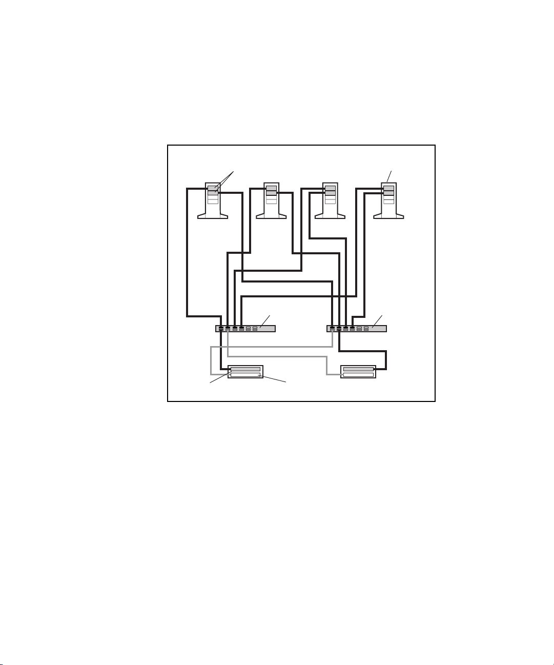
2-60 Compaq Parallel Database Cluster Model PDC/O2000 for Oracle8i and Windows 2000 Administrator Guide
Active/Active Configuration with Two RA4000/RA4100 Arrays
Figure 2-25 shows an active/active I/O path configuration for a redundant
FC-AL in a four-node cluster with two RA4000/RA4100 Arrays.
Fibre Host
Adapters (2)
Node 1 Node 2 Node 3 Node 4
FC-AL
Switch/Storage
Hub #1
Active
Array Controller
RA4000/4100
Array #1
Standby
Array Controller
RA4000/4100
Array #2
ProLiant
Servers (4)
FC-AL
Switch/Storage
Hub #2
Figure 2-25. Active/active configuration with two RA4000/RA4100 Arrays
Page 85

Cluster Architecture 2-61
Active/Active Configuration with Three RA4000/RA4100 Arrays
Figure 2-26 shows an active/active I/O path configuration for a redundant
FC-AL in a four-node cluster with three RA4000/RA4100 Arrays.
Fibre Host
Adapters (2)
Node 1 Node 2 Node 3 Node 4
FC-AL
Switch/Storage
Hub #1
Active
Array Controller
RA4000/4100
Array #1
RA4000/4100
Array #3
Standby
Array Controller
RA4000/4100
ProLiant
Servers (4)
FC-AL
Switch/Storage
Hub #2
Array #2
Figure 2-26. Active/active configuration with three RA4000/RA4100 Arrays
Page 86

2-62 Compaq Parallel Database Cluster Model PDC/O2000 for Oracle8i and Windows 2000 Administrator Guide
Active/Active Configuration with Four RA4000/RA4100 Arrays
Figure 2-27 shows an active/active I/O path configuration for a redundant
FC-AL in a four-node cluster with four RA4000/RA4100 Arrays.
Fibre Host
Adapters (2)
Node 1 Node 2 Node 3 Node 4
FC-AL
Switch/Storage
Hub #1
Active
Array Controller
RA4000/4100
Array #1
RA4000/4100
Array #3
Standby
Array Controller
RA4000/4100
RA4000/4100
ProLiant
Servers (4)
FC-AL
Switch/Storage
Hub #2
Array #2
Array #4
Figure 2-27. Active/active configuration with four RA4000/RA4100 Arrays
Page 87

Cluster Architecture 2-63
Active/Active Configuration with Five RA4000/RA4100 Arrays
Figure 2-28 shows an active/active I/O path configuration for a redundant
FC-AL in a four-node cluster with five RA4000/RA4100 Arrays.
Fibre Host
Adapters (2)
Node 1 Node 2 Node 3 Node 4
FC-AL
Switch/Storage
Hub #1
RA4000/4100
Array #1
Standby
Array Controller
RA4000/4100
Array #5
Active
Array Controller
RA4000/4100
Array #3
RA4000/4100
Array #2
RA4000/4100
Array #4
ProLiant
Servers (4)
FC-AL
Switch/Storage
Hub #2
Figure 2-28. Active/active configuration with five RA4000/RA4100 Arrays
Page 88

2-64 Compaq Parallel Database Cluster Model PDC/O2000 for Oracle8i and Windows 2000 Administrator Guide
Summary of I/O Path Failure and Failover
Scenarios for Redundant FC-ALs
Table 2-7 identifies possible I/O path failure events in redundant FC-ALs for
active/standby configurations with one RA4000/RA4100 Array and the
failover response, if any, implemented by Secure Path for each failure.
Table 2-7
I/O Path Failure and Failover Scenarios in Redundant FC-ALs for Active/Standby
Configurations With One RA4000/RA4100 Array
Description of Failure Failover Response
The active array controller in the
RA4000/RA4100 Array fails.
The standby array controller in the
RA4000/RA4100 Array fails.
The Fibre Channel cable
connection between the active
array controller and its Storage
Hub or FC-AL Switch is broken.
The Fibre Channel cable
connection between the standby
array controller and its Storage
Hub or FC-AL Switch is broken.
The Storage Hub or FC-AL Switch
connected to the active array
controller fails.
The Storage Hub or FC-AL Switch
connected to the standby array
controller fails.
The Fibre Channel cable
connection between a Fibre Host
Adapter and the Storage Hub or
FC-AL Switch connected to the
active array controller is broken.
Secure Path forces a complete failover to the standby I/O path
components, including the standby Fibre Host Adapter in each
node, the other Storage Hub or FC-AL Switch, the standby array
controller in the RA4000/RA4100 Array, and Fibre Channel cables.
None
Secure Path forces a complete failover to the standby I/O path
components, including the standby Fibre Host Adapter in each
node, the other Storage Hub or FC-AL Switch, the standby array
controller in the RA4000/RA4100 Array, and Fibre Channel cables.
None
Secure Path forces a complete failover to the standby I/O path
components, including the standby Fibre Host Adapter in each
node, the other Storage Hub or FC-AL Switch, the standby array
controller in the RA4000/RA4100 Array, and Fibre Channel cables.
None
Secure Path forces a complete failover to the standby I/O path
components, including the standby Fibre Host Adapter in each
node, the other Storage Hub or FC-AL Switch, the standby array
controller in the RA4000/RA4100 Array, and Fibre Channel cables.
continued
Page 89

Cluster Architecture 2-65
Table 2-7
I/O Path Failure and Failover Scenarios in Redundant FC-ALs for Active/Standby
Configurations With One RA4000/RA4100 Array
Description of Failure Failover Response
continued
The Fibre Channel cable
connection between a Fibre Host
Adapter and the Storage Hub or
FC-AL Switch connected to the
standby array controller is broken.
A Fibre Host Adapter connected to
the Storage Hub or FC-AL Switch
that connects to the active array
controller fails.
A Fibre Host Adapter connected to
the Storage Hub or FC-AL Switch
that connects to the standby array
controller fails.
None
Secure Path forces a complete failover to the standby I/O path
components, including the standby Fibre Host Adapter in each
node, the other Storage Hub or FC-AL Switch, the standby array
controller in the RA4000/RA4100 Array, and Fibre Channel cables.
None
Page 90

2-66 Compaq Parallel Database Cluster Model PDC/O2000 for Oracle8i and Windows 2000 Administrator Guide
Table 2-8 identifies possible I/O path failure events for active/standby
configurations with two or more RA4000/RA4100 Arrays and the failover
response, if any, implemented by Secure Path for each failure.
Table 2-8
I/O Path Failure and Failover Scenarios in Redundant FC-ALs for Active/Standby
Configurations With Two or More RA4000/RA4100 Arrays
Description of Failure Failover Response
The active array controller in one
RA4000/RA4100 Array fails.
The standby array controller in one
RA4000/RA4100 Array fails.
The Fibre Channel cable
connection between the active
array controller in one
RA4000/RA4100 Array and its
Storage Hub or FC-AL Switch is
broken.
The Fibre Channel cable
connection between the standby
array controller in one
RA4000/RA4100 Array and its
Storage Hub or FC-AL Switch is
broken.
The Storage Hub or FC-AL Switch
that is connected to the active
array controller in each
RA4000/RA4100 Array fails.
The Storage Hub or FC-AL Switch
that is connected to the standby
array controller in each
RA4000/RA4100 Array fails.
Secure Path forces a complete failover to the standby I/O path
components, including the standby Fibre Host Adapter in each
node, the other Storage Hub or FC-AL Switch, the standby array
controller in each RA4000/RA4100 Array, and Fibre Channel cables.
None
Secure Path forces a complete failover to the standby I/O path
components, including the standby Fibre Host Adapter in each
node, the other Storage Hub or FC-AL Switch, the standby array
controller in each RA4000/RA4100 Array, and Fibre Channel cables.
None
Secure Path forces a complete failover to the standby I/O path
components, including the standby Fibre Host Adapter in each
node, the other Storage Hub or FC-AL Switch, the standby array
controller in each RA4000/RA4100 Array, and Fibre Channel cables.
None
continued
Page 91

Cluster Architecture 2-67
Table 2-8
I/O Path Failure and Failover Scenarios in Redundant FC-ALs for Active/Standby
Configurations With Two or More RA4000/RA4100 Arrays
Description of Failure Failover Response
continued
The Fibre Channel cable
connection between the Storage
Hub or FC-AL Switch that is
connected to the active array
controllers and a Fibre Host
Adapter is broken.
The Fibre Channel cable
connection between the Storage
Hub or FC-AL Switch that is
connected to the standby array
controllers and a Fibre Host
Adapter is broken.
A Fibre Host Adapter connected to
the Storage Hub or FC-AL Switch
that is connected to the active
array controllers fails.
A Fibre Host Adapter connected to
the Storage Hub or FC-AL Switch
that is connected to the standby
array controllers fails.
Secure Path forces a complete failover to the standby I/O path
components, including the standby Fibre Host Adapter in each
node, the other Storage Hub or FC-AL Switch, the standby array
controller in the each RA4000/RA4100 Array, and Fibre Channel
cables.
None
Secure Path forces a complete failover to the standby I/O path
components, including the standby Fibre Host Adapter in each
node, the other Storage Hub or FC-AL Switch, the standby array
controller in each RA4000/RA4100 Array, and Fibre Channel cables.
None
Page 92

2-68 Compaq Parallel Database Cluster Model PDC/O2000 for Oracle8i and Windows 2000 Administrator Guide
Table 2-9 identifies possible I/O path failure events in redundant FC-ALs for
active/active configurations with two or more RA4000/RA4100 Arrays and
the failover response, if any, implemented by Secure Path for each failure.
Table 2-9
I/O Path Failure and Failover Scenarios in Redundant FC-ALs for Active/Active
Configurations With Two or More RA4000/RA4100 Arrays
Description of Failure Failover Response
The active array controller in one
RA4000/RA4100 Array fails.
The standby array controller in one
RA4000/RA4100 Array fails.
The Fibre Channel cable
connection between the active
array controller in one
RA4000/RA4100 Array and its
Storage Hub or FC-AL Switch is
broken.
The Fibre Channel cable
connection between the standby
array controller in one
RA4000/RA4100 Array and its
Storage Hub or FC-AL Switch is
broken.
Secure Path makes the standby array controller in the
RA4000/RA4100 Array active and reroutes I/O activity to that array
controller. The Storage Hub or FC-AL Switch that is connected to
the new active array controller becomes the active I/O path to this
RA4000/RA4100 Array. In each node, I/O activity between the Fibre
Host Adapter that is connected to the failed array controller is
rerouted to the second Fibre Host Adapter in the pair, but only along
the I/O path to the affected RA4000/RA4100 Array. The first Fibre
Host Adapter in each node continues to be the active I/O path for
active array controllers in other RA4000/RA4100 Arrays to which it
is connected.
None
Secure Path makes the active array controller to which the failed
cable is connected inactive. The standby array controller in the
RA4000/RA4100 Array becomes active. I/O activity is routed
through the Fibre Channel cable installed to the new active array
controller and the other Storage Hub or FC-AL Switch. In each
node, I/O activity between the Fibre Host Adapter that is connected
to the failed array controller is rerouted to the second Fibre Host
Adapter in the pair, but only along the I/O path to the affected
RA4000/RA4100 Array. The first Fibre Host Adapter in each node
continues to be the active I/O path for active array controllers in
other RA4000/RA4100 Arrays to which it is connected.
None
continued
Page 93

Cluster Architecture 2-69
Table 2-9
I/O Path Failure and Failover Scenarios in Redundant FC-ALs for Active/Active Configurations
With Two or More RA4000/RA4100 Arrays
Description of Failure Failover Response
continued
A Storage Hub or FC-AL Switch
fails.
The Fibre Channel cable
connection between a Storage
Hub or FC-AL Switch and a Fibre
Host Adapter in one node is
broken.
A Fibre Host Adapter in a node
fails.
Secure Path makes each active array controller to which the failed
Storage Hub or FC-AL Switch is connected inactive. The standby
array controller in each affected RA4000/RA4100 Array becomes
the active array controller. The Storage Hub or FC-AL Switch that is
connected to the new active array controllers becomes the active
I/O path for these RA4000/RA4100 Arrays. In each node, the Fibre
Host Adapter that is connected to the failed Storage Hub or FC-AL
Switch becomes inactive, and all I/O activity is rerouted through the
other Fibre Host Adapter in the pair and the remaining active
Storage Hub or FC-AL Switch.
Secure Path makes all I/O path connections between the affected
Fibre Host Adapter and active array controllers inactive. The
standby array controller in every affected RA4000/RA4100 Array
becomes the active array controller. The Storage Hub or FC-AL
Switch connected to the newly active array controllers becomes the
active I/O path for the entire FC-AL. The Storage Hub or FC-AL
Switch connected to the failed Fibre Channel cable becomes
inactive. The second Fibre Host Adapter in each node, which is
connected to the only active Storage Hub or FC-AL Switch,
becomes the only active Fibre Host Adapter in the node’s pair.
Secure Path makes all I/O path connections between the affected
Fibre Host Adapter and active array controllers inactive. The
standby array controller in every affected RA4000/RA4100 Array
becomes the active array controller. The Storage Hub or FC-AL
Switch connected to the newly active array controllers becomes the
active I/O path for the entire FC-AL. The Storage Hub or FC-AL
Switch connected to the failed Fibre Host Adapter becomes
inactive. The second Fibre Host Adapter in each node, which is
connected to the only active Storage Hub or FC-AL Switch,
becomes the only active Fibre Host Adapter in the node’s pair.
Page 94

2-70 Compaq Parallel Database Cluster Model PDC/O2000 for Oracle8i and Windows 2000 Administrator Guide
Cluster Interconnect Options
The cluster interconnect is the data path over which all of the nodes in a
cluster communicate. The nodes use the cluster interconnect data path to:
■ Communicate individual resource and overall cluster status.
■ Send and receive heartbeat signals.
■ Coordinate database locks through the Oracle Integrated Distributed
Lock Manager.
NOTE: Several terms for cluster interconnect are used throughout the industry. Others
are: private LAN, private interconnect, system area network (SAN), and private network.
Throughout this guide, the term cluster interconnect is used.
A PDC/O2000 cluster running Oracle8i Parallel Server uses an Ethernet
cluster interconnect. An Ethernet cluster interconnects can be redundant or
non-redundant. A redundant cluster interconnect is recommended because it
uses redundant hardware to provide fault tolerance along the entire cluster
interconnect path.
Ethernet Cluster Interconnect
IMPORTANT: The cluster management software for the Ethernet cluster interconnect
requires the use of TCP/IP. When configuring the Ethernet cluster interconnect, be sure to
enable TCP/IP.
NOTE: Refer to the technical white paper Supported Ethernet Interconnects for Compaq
Parallel Database Clusters Using Oracle Parallel Server (ECG062/0299) for detailed
information about configuring redundant and non-redundant Ethernet cluster
interconnects. This document is available at
www.compaq.com/support/techpubs/whitepapers
Page 95

Cluster Architecture 2-71
Non-Redundant Ethernet Cluster Interconnect Components
The following components are used in a non-redundant Ethernet cluster
interconnect:
■ One Ethernet adapter in each cluster node
■ Ethernet cables and a switch or hub
G For two-node PDC/O2000 clusters, you can either use one Ethernet
crossover cable or one 100-Mbit/second Ethernet switch or hub and
standard Ethernet cables to connect the two servers.
G For PDC/O2000 clusters with three or more nodes, you use one
100-Mbit/second Ethernet switch and standard Ethernet cables to
connect the servers.
Redundant Ethernet Cluster Interconnect Components
The following components are used in a redundant Ethernet cluster
interconnect:
■ Two Ethernet adapters in each cluster node
■ Ethernet cables and switches or hubs
G For two-node PDC/O2000 clusters, you can use two
100-Mbit/second Ethernet switches or hubs with cables to connect
the servers.
G For PDC/O2000 clusters with three or more nodes, you use two
100-Mbit/second Ethernet switches connected by Ethernet cables to
a separate Ethernet adapter in each server.
NOTE: In a redundant Ethernet cluster configuration, one Ethernet crossover cable must
be installed between the two Ethernet switches or hubs that are dedicated to the cluster
interconnect.
Page 96

2-72 Compaq Parallel Database Cluster Model PDC/O2000 for Oracle8i and Windows 2000 Administrator Guide
Ethernet Cluster Interconnect Adapters
To implement the Ethernet cluster interconnect, each cluster node must be
equipped with Ethernet adapters capable of 100-Mbit/second transfer rates.
Some adapters may be capable of operating at both 10-Mbit/second and
100-Mbit/second; however, Ethernet adapters used for the cluster interconnect
must run at 100-Mbit/second.
The Ethernet adapters must have passed Windows 2000 Advanced HCT
certification.
NOTE: If you are using dual-port Ethernet adapters in a non-redundant Ethernet cluster
interconnect, you can use one port for the Ethernet cluster interconnect and the second
port for the client LAN. Refer to the technical white paper Supported Ethernet
Interconnects for Compaq Parallel Database Clusters Using Oracle Parallel Server for
detailed information about configuring redundant Ethernet cluster interconnects. This
document is available at
www.compaq.com/support/techpubs/whitepapers
For detailed information about installing an Ethernet cluster interconnect, see
Chapter 5, “Installation and Configuration.”
Ethernet Switch
IMPORTANT: The Ethernet switch or switches used with the Ethernet cluster
interconnect must be dedicated to the cluster interconnect. They cannot be connected to
the client network (LAN) or to servers that are not part of the PDC/O2000 cluster.
When an Ethernet cluster interconnect is used in a cluster with three or more
nodes, a 100-Mbit/second Ethernet switch is required for the cluster
interconnect path. The 100-Mbit/second Ethernet switch handles the higher
network loads essential to the uninterrupted operation of the cluster. An
Ethernet hub cannot be used.
Page 97

Cluster Architecture 2-73
Ethernet Cluster Interconnect Diagrams
Figure 2-29 shows the non-redundant Ethernet cluster interconnect
components used in a two-node PDC/O2000 cluster. These components
include a dual-port Ethernet adapter in each node. The top port on each adapter
connects by Ethernet crossover cable to the top port on the adapter in the other
node. The bottom port on each adapter connects by Ethernet cable to the client
LAN switch or hub.
Ethernet Crossover Cable
Dual-port
Ethernet
Adapter
for Ethernet Cluster Interconnect
Ethernet Cables
for Client LAN
Dual-port
Ethernet
Adapter
Node 1
Client LAN
Hub or Switch
Node 2
Figure 2-29. Non-redundant Ethernet cluster interconnect using a
crossover cable
Page 98

2-74 Compaq Parallel Database Cluster Model PDC/O2000 for Oracle8i and Windows 2000 Administrator Guide
Figure 2-30 shows another option for a non-redundant Ethernet cluster
interconnect in a two-node PDC/O2000 cluster. These include an Ethernet
adapter in each node connected by Ethernet cables to an Ethernet switch or
hub.
RA4000/4100 Array
Storage Hub/Switch
Ethernet Adapter Ethernet Adapter
Node 1
Storage Hub/Switch
Ethernet
cables
Client LAN
Node 2
Figure 2-30. Non-redundant Ethernet cluster using an Ethernet switch or hub
Because Ethernet switches are required in PDC/O2000 clusters with three or
more nodes, using an Ethernet switch instead of a crossover cable makes it
easier to upgrade the cluster interconnect if more servers are added to the
cluster.
IMPORTANT: Crossover cables and Ethernet hubs cannot be used in PDC/O2000 clusters
with a redundant Ethernet cluster interconnect or in PDC/O2000 clusters with three or
more nodes.
Page 99

Cluster Architecture 2-75
Figure 2-31 shows the redundant Ethernet cluster interconnect components
used in a two-node PDC/O2000 cluster.
Ethernet Switch/Hub #1
for Cluster Interconnect
Ethernet Switch/Hub #2
for Cluster Interconnect
Crossover
Cable
Dual-port
Ethernet
Adapters (2)
Node 1
Crossover
Cable
Client LAN
Hub/Switch #2
Node 2
Client LAN
Hub/Switch #1
Dual-port
Ethernet
Adapters (2)
Figure 2-31. Redundant Ethernet cluster interconnect for a two-node
PDC/O2000 cluster
These components include two dual-port Ethernet adapters in each cluster
node. The top port on each adapter connects by Ethernet cable to one of two
Ethernet switches or hubs provided for the cluster interconnect. The bottom
port on each adapter connects by Ethernet cable to the client LAN for the
cluster. A crossover cable is installed between the two Ethernet switches or
hubs used in the Ethernet cluster interconnect.
Page 100

2-76 Compaq Parallel Database Cluster Model PDC/O2000 for Oracle8i and Windows 2000 Administrator Guide
Local Area Network
NOTE: For the PDC/O2000, the client LAN and the cluster interconnect must be treated as
separate networks. Do not use either network to handle the other network’s traffic.
Every client/server application requires a local area network, or LAN, over
which client machines and servers communicate. In the case of a cluster, the
hardware components of the client LAN are no different than in a standalone
server configuration.
The software components used by network clients should have the ability to
detect node failures and automatically reconnect the client to another cluster
node. For example, Net8, Oracle Call Interface (OCI) and Transaction Process
Monitors can be used to address this issue.
NOTE: For complete information on how to ensure client auto-reconnect in an Oracle8i
Parallel Server environment, contact your Oracle representative.
 Loading...