

Hp COMPAQ PROLIANT 3000, COMPAQ PROLIANT 1500, COMPAQ PROLIANT 4500, COMPAQ PROLIANT 1600, COMPAQ PROLIANT 5000 PCI Bus Numbering in a Microsoft Windows NT Environment
...Page 1

Integration Note
December 2000
13UK-1200A-WWEN
Prepared by OS Integration
Engineering
Compaq Compute r Corporation
Contents
Executive Overview.....................3
PCI Bus Architecture
Terminology.................................4
PCI Hot Plug Terminology..........5
PCI System Overview..................5
PCI Architecture and Bridged
Controllers..................................6
PCI BIOS ...................................8
PCI Bus Numbering...................8
PCI BIOS Discovery...................8
Configuration Changes............11
Windows NT and PCI Bus
Numbering..................................11
PCI Bus Numbering and
Network Controllers..................11
Disk Renumbering....................12
Hardware, Software, and
Configuration Tools...................13
Compaq Servers and Option
Hardware .................................13
Planning a PCI System
Configuration.............................17
Before Modifying an Existing
System.....................................18
Planning the New
Configuration............................18
Step-By-Step Review...............19
PCI Test Configurations with
ProLiant Servers........................19
Configuration A, ProLiant
ML530......................................20
Configuration B, ProLiant
8000.........................................23
Configuration C, ProLiant
DL580 ......................................29
Compaq Support Software
and Utilities ..............................36
Additional Troubleshooting
Tips.............................................39
Summary....................................40
Appendices A-D.........................41
PCI Bus Numbering in a
Microsoft Windows NT
Environment
Abstract: Computing environments change rapidly to support
business requirements. Typical network PCI-based servers contain a
large number of expansion slots on multiple buses to allow for
system growth. This means that multiple network and disk
controllers of the same type may be installed in one server, with the
intent that each installed controller supports a separate unique
function. This can make it difficult to understand the physical and
logical implications of PCI bus numbering.
This document provides information to help systems engineering
professionals understand how Microsoft Windows NT handles PCI
bus numbering when controllers are physically added, moved, or
removed from a server configuration. This document also includes
ideas and suggestions that can help systems professionals avoid
network downtime due to configuration changes.
IMPORTANT: During the development of Microsoft Windows
2000, Compaq and Microsoft worked closely together effectively
implementing Windows 2000 on Compaq hardware. Through this
partnership, device detection improved, eliminating PCI bus
numbering issues in the Windows 2000 environment. Windows 2000
checks and resets registry settings automatically, unlike its
predecessor that does not reset the registry settings after discovering
unbound devices.
The following documents were either used as references to produce
this white paper or are mentioned as recommended related reading
material:
• PCI System Architecture, Third Edition, MindShare, Inc. Tom
Shanley and Don Anderson, November, 1995.
• PCI Bus Balancing and Optimization on Compaq ProLiant
Servers, March, 1998 – Doc ID ECG073/0398.
• Where Do I Plug the Cable? Solving the Logical-Physical Slot
Numbering Problem, December 1996 – Doc ID 209A/1296.
• Deploying PCI Hot Plug on Compaq
Windows NT
Environment, July 1997 - Doc ID 064A/0797.
Servers in a Microsoft
Help us improve our technical communication. Let us know what you think
about the technical information in this document. Your feedback is valuable
and will help us structure future communications. Please send your
comments to:
CompaqNT@compaq.com
Page 2

PCI Bus Numbering in a Microsoft Windows NT Environment 2
Notice
©2000 Compaq Computer Corporation.
Compaq, the Compaq logo, NetFlex, ProLiant, and SmartStart are registered United States Patent and
Trademark Office.
SoftPaq is a trademark and/or service mark of Compaq Computer Corporation.
Netelligent is a trademark and/or service mark of Compaq Information Technologies Group, L.P. in the
U.S. and/or other countries.
Microsoft, Windows, Windows NT, and Windows 2000 are trademarks and/or registered trademarks of
Microsoft Corporation.
Pentium, Xeon, Pentium II Xeon, and Pentium III Xeon are registered trademarks of Intel Corporation.
Adobe, Acrobat, and the Acrobat logo are trademarks of Adobe Systems, Inc.
Other product names mentioned herein may be trademarks and/or registered trademarks of their respective
companies.
The information in this publication is subject to change without notice and is provided “AS IS” WITHOUT
WARRANTY OF ANY KIND. THE ENTIRE RISK ARISING OUT OF THE USE OF THIS
INFORMATION REMAINS WITH RECIPIENT. IN NO EVENT SHALL COMPAQ BE LI AB LE FOR
ANY DIRECT, CONSEQUENTIAL, INCIDENTAL, SPECIAL, PUNITIVE OR OTHER DAMAGES
WHATSOEVER (INCLUDING WITHOUT LIMITATION, DAMAGES FOR LOSS OF BUSINESS
PROFITS, BUSINESS INTERRUPTION OR LOSS OF BUSINESS INFO RMATION), EVEN IF
COMPAQ HAS BEEN ADVISED OF THE POSSIBILITY OF SUCH DAMAGES.
The limited warranties for Compaq products are exclusively set forth in the documentation accompanying
such products. Nothing herein should be construed as constituting a further or additional warranty.
This publication does not constitute an endorsement of the product or products that were tested. The
configuration or configurations tested or described may or may not be the only available solution. This test
is not a determination or product quality or correctness, nor does it ensure compliance with any federal
state or local requirements.
PCI Bus Numbering in a Microsoft Windows NT Environment
Integration Note prepared by OS Integration Engineering
Fourth Edition (December 2000)
Document Number 13UK-1200A-WWEN
13UK-1200A-WWEN
Page 3

PCI Bus Numbering in a Microsoft Windows NT Environment 3
Executive Overview
The term Peripheral Component Interconnect, commonly known as PCI, refers to the bus
architecture standard. The PCI bus technology has become an industry standard; today’s servers
provide a large number of expansion slots and can be populated with a greater number of PCI
disk and network controllers. PCI buses provide fast access between controllers and/or system
memory and the host processor. PCI buses offer a significant performance advantage over EISA
buses.
The PCI Special Interest Group (SIG) is an unincorporated association of members of the
microcomputer industry set up for the purpose of monitoring and enhancing the development of
the PCI architecture. The PCI Steering Committee is a group of nine companies that oversees SIG
activities and reviews formal recommendations for changes to PCI Specification(s). Compaq is a
member of the SIG Steering Committee and actively proposes and contributes new design
functions for future revisions to the PCI Specification.
Later in this document, examples
are provided in two test scenarios,
illustrating what happens to PCI
bus numbering when configuration
changes occur.
during system start up. Windows NT uses these numbers to identify bridged controllers. If
controllers are added to an existing system, the PCI bus numbering might change. This change
might affect the operation of your system.
This white paper provides information to help systems professionals understand how the PCI
Specification addresses server bus numbering assignments. This document discusses:
• How the PCI BIOS detects and numbers PCI buses and bridges.
• What happens to PCI Bus numbering at each system start up.
• How adding or removing PCI devices might cause a renumbering of PCI buses.
• How Windows NT handles bus numbering in the Windows NT Registry.
• How to prevent PCI bus numbering mismatches from occurring.
This document contains several examples to demonstrate PCI bus numbering. After reading this
document, you should be able to properly configure and/or reconfigure a Windows NT system when
PCI bus numbers are reassigned with minimal interruption to the network.
PCI bus technology development continues to advance at a rapid pace to
meet customer’s business requirements. Server technology includes
equipment, such as the ProLiant 8000 with multiple PCI buses. The
computing capabilities of these servers can be further expanded through
PCI controllers and PCI bridged devices such as the Smart Array 4250ES
Controller. Each PCI bus in the system is numbered by the PCI BIOS
13UK-1200A-WWEN
Page 4

PCI Bus Numbering in a Microsoft Windows NT Environment 4
PCI Bus Architecture Terminology
Table 1 lists some terms related to PCI Bus Architecture terminology. Some of the terminology
defined in this table was referenced from PCI System Architecture, Third Edition, MindShare,
Inc. Tom Shanley and Don Anderson. (November, 1995.)
Table 1. PCI bus architecture standard terms
Bridge Bridge is the device, providing connectivity between two independent
Bus Number Bus number is a number in the range 0…255 that uniquely selects a PCI
Device ID Device ID is a number in the range 0…31 that uniquely selects a device
Downstream When a transaction is initiated and is passed through one or more PCI-to-
Dual-Peer PCI Bus A system architecture providing high-bandwidth I/0 because two buses
Highly Parallel
Architecture
PCI Peripheral Component Interconnect refers to a bus based on the PCI
PCI BIOS PCI BIOS functions provides a software interface to the hardware used to
PCI Bridge The device that provides the bridge between two independent buses.
PCI-to-PCI Bridge PCI-to-PCI bridge is a system architecture where an additional PCI bus is
buses.
bus.
on a PCI bus.
PCI bridges flowing away from the host processor, it is said to be moving
downstream.
can operate simultaneously (i.e., in parallel) is called a dual-peer-PCI bus.
A system architecture using dual memory controllers, dual-peer-P CI
buses to deliver optimized multiprocessing support to deliver increased
system throughput and increased system performance when compared to
traditional x86-based designs is said to be highly parallel.
Local Bus Specification, through which industry-standard peripheral
controllers connect to computer systems.
implement a PCI based system.
PCI bridges can reside on the system and can reside on controllers. PCI
bridges help with signal integrity and allow more devices to be added per
system.
bridged off another PCI bus (i.e., in series).
Peer-to-Peer PCI Buses PCI buses that occupy the same ranking in the PCI bus hierarchy (with
Primary Bus The PCI bus closest to the host processor that is connected to one side of
Secondary Bus The PCI bus detected after the Primary Bus is called the Secondary Bus.
Tertiary Bus The Tertiary bus resides furthest from host processor that is connected to
Triple-Peer PCI Bus System architecture operating with three PCI buses on a single server is
Upstream When a transaction is initiated and is passed through one or more PCI-to-
13UK-1200A-WWEN
respect to the host bus) are referred to as Peer PCI buses.
the inter-bus bridge is the Primary Bus (numbering always starts at 0).
one side of the inter-bus bridge.
referred to as a Triple-Peer PCI Bus.
PCI bridges flowing towards the host processor, it is said to be moving
upstream.
Page 5

PCI Bus Numbering in a Microsoft Windows NT Environment 5
PCI Hot Plug Terminology
Table 2 lists some terms related to PCI Hot Plug Terminology; however, this is not a complete list.
The terms described here are those that relate to Hot Plug capabilities experienced in this
document.
Table 2. PCI hot plug standard terms
*Hot Add
Hot Plug Aware Indicates that a piece of software, such as a device driver, can take
Hot Plug Slot A PCI slot capable of being powered down without interfering with the other
Hot Replacement The ability to remove PCI controllers from a system while the system is
*Hot Upgrade
PCI Hot Plug The ability to physically insert or remove industry-standard PCI adapters
* Not available in initial release of PCI Hot Plug technology for Windows NT
The ability to add existing PCI controllers and drivers to next generation
controllers and drivers while a system is running, without shutting down
the system.
advantage of the PCI Hot Plug capabilities of a system.
slots in the system, and without shutting the system down.
running and replace them with equivalent PCI controllers, without removing
power to the server and without reconfiguring or reloading software
support.
The ability to upgrade existing PCI controllers and drivers to next generation
controllers and drivers while a system is running, without shutting down the
system.
while the system is running without disrupting the operation of other
devices in the system.
PCI System Overview
This section reviews some of the basics of buses including PCI architecture and bridged
controllers, PCI BIOS, PCI bus numbering, PCI BIOS discovery, and configuration changes to
the bus numbering.
13UK-1200A-WWEN
Page 6
PCI Bus Numbering in a Microsoft Windows NT Environment 6
PCI Architecture and Bridged Controllers
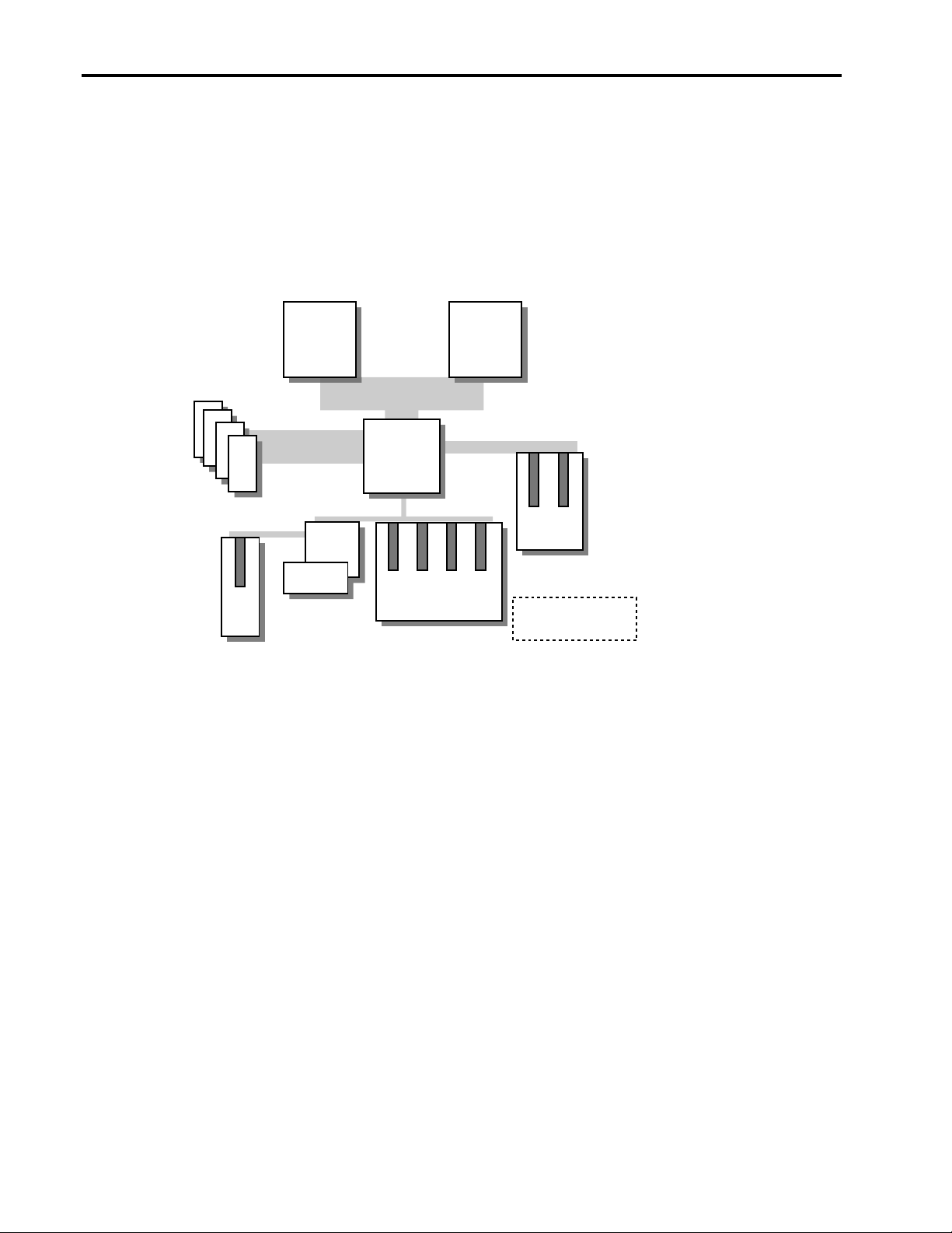
There are four primary bus expansion schemes for PCI systems, namely the PCI-to-PCI bridge
architecture, Dual-Peer PCI Bus architecture (see Figure 1), Highly-Parallel Bus architecture (see
Figure 2), and Triple-Peer PCI Bus architecture (see Figure 3). The Compaq servers discussed in
this white paper and used in the Integration Lab testing include these PCI architecture system
designs. Refer to the “Compaq Server and Option Hardware” section of this white paper for more
information.
133MHz FSB
Pentium III
133MHz
1.06GB/s
133MHz
1.06GB/s
133MHz
SDRAM
DIMMs
OSB4
SuperIO
Controller
ISA
Slot
Figure 1. Dual-peer PCI bus architecture in the ProLiant ML350
RCC 3.0
PCI/Memory
Controller
133 MB/s
4 x 32-Bit PCI Slots
133MHz FSB
Pentium III
267 MB/s
2 x 64-Bit
PCI Slots
Server Feature Card
in 32-bit PCI slot
13UK-1200A-WWEN
Page 7
PCI Bus Numbering in a Microsoft Windows NT Environment 7
Pentium III
Xeon
133MHz
SDRAM
DIMMs
33MHz/32-bit
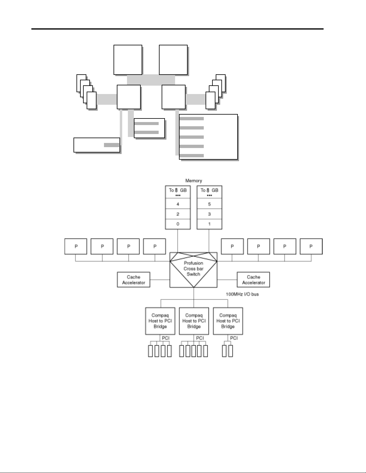
Figure 2. Highly parallel PCI bus architecture in the ProLiant ML530
133MHz 133MHz
PCI slot
RCC 3.0
controller
66MHz/64-bit
PCI slots
Pentium III
Xeon
RCC 3.0
controller
SDRAM
DIMMs
33MHz/64-bit
PCI slots
Figure 3. Triple-peer PCI bus architecture in the ProLiant 8000
PCI bridges are not limited to the computer system; controllers can include them also. Hardware
manufactures such as Compaq include PCI bridges on controllers to help with signal integrity,
enabling more devices to be added per system. Data transfers from the host bus, through the
primary PCI bus, through the PCI-to-PCI bridge on the controller, and finally to the PCI device.
For example, an intelligent device such as a Smart Array 4250ES Controller contains a PCI
bridge.
13UK-1200A-WWEN
Page 8

PCI Bus Numbering in a Microsoft Windows NT Environment 8
PCI BIOS
The PCI BIOS specification defines the rules regarding implementation of the PCI BIOS and the
software that it calls. The PCI BI OS supplies servic es t o the hardw are pla tf orm, such as
determining the range of PCI buses present in the system and searching for all instances of a
specific PCI device. The PCI BIOS for each hardware manufacturer is platform-specific. The
operating system, application programs, and device drivers do not directly access the PCI
configuration area. On Compaq servers you can review system configuration information by
accessing the Compaq System Configuration Utility during system startup before the operating
system initialization (by pressing F10). The System Configuration Utility may be installed on a
server with the Compaq SmartStart and Support Software CD or from a diskette to update the
server configuration.
PCI Bus Numbering
At startup time, the PCI BIOS is aware only of the existence of PCI bus 0, the first bus number
detected on the Primary PCI Bus. The PCI BIOS assigns numbers to each PCI bus and bridge it
detects during system initialization. PCI bus numbers reassign each time the system starts and the
discovery process begins again. Each PCI device receives the same PCI bus number if no changes
have been made.
Each time the server restarts the PCI BIOS must walk the base PCI bus (starting at bus 0),
subsequent bridges, and bridged devices to search and identify other PCI buses as if it were the
first time. Each time the PCI BIOS discovers another PCI bus after a physical configuration
change is made, it increments the bus number and continues to walk the bus until all other buses
are discovered.
As it discovers each bus and/or bridge, the PCI BIOS:
• Records each unique bus number
• Associates the bus number to a bus or bridged PCI device
When the System Configuration Utility runs it builds a picture of the bus “tree” that represents
the overall system topology. The System Configuration Utility displays the slot and bus number
assignment for each PCI device in the server. Since controllers are physically installed in
numbered slots, the PCI BIOS does not detect the numbers assigned to the slots, only the PCI
devices installed in the slots. Systems professionals typically use slot numbers to identify and
record the physical placement of controllers when configuring network systems. This document
should help you predict how the PCI BIOS assigns and/or reassign bus numbers and how to
associate these assignments to the physical slot numbers. Slot number assignments remain
constant with a controller for as long as the controller is installed in a particular slot.
PCI BIOS Discovery
The following examples illustrate the PCI BIOS discovery and bus number assignment process
for PCI buses, non-bridged controllers, and bridged controllers. The actual discovery process
includes other components not shown here that reside on the PCI bus, such as video or embedded
SCSI devices. However, this document omits these other components to simplify the example.
PCI Bus numbering is determined by the order of detection of each PCI bus discovered in a
server configuration. The manufacturer defines the detection order for each server. Refer to
“Table 11. PCI Bus Number Order of Detection Matrix” for Compaq ProLiant servers.
13UK-1200A-WWEN
Page 9

PCI Bus Numbering in a Microsoft Windows NT Environment 9
IMPORTANT: PCI Bus numbers are assigned in “device detection order,” not by slot
numbering.
Bus numbers are assigned during
bus initialization according to
predefined hardware designators.
The bus numbers may not appear to
follow a set increment and some
numbers may be skipped.
However, by this method, these
hardware designators prevent
overlays in bus numbering from
occurring.
process continues until all PCI controllers and controllers with bridged buses on the Primary Bus
are detected. The PCI BIOS then continues the discovery process on the Secondary Bus until all
PCI buses are detected.
The diagram in Table 3 shows an example of the discovery process. Table 3 does not represent all
the PCI slots and bus assignment possibilities, it depicts snapshot of what occurs when controllers
are loaded in the server.
Table 3. Example of PCI bus number detection order for the ProLiant ML350 (a dual-peer system)
ProLiant ML350 PCI Server Architecture
PCI BIOS Discovery Process
! Host Bus
" Primary PCI Bus First 0
! Slot 1 – Server Feature Card Second 0
! Slot 4 – Empty Third 0
! Slot 5 – Empty Fourth 0
! Slot 6 – NC3131 Fast Ethernet NIC Fifth 1
" Secondary PCI Bus Sixth 5
! Slot 2 – Smart Array 5300 Controller Seventh 5
! Slot 3 – Empty Eighth 5
End of bus
discovery
Dual-Peer PCI Bus – The Compaq ProLiant ML350 server, an example
of the dual-peer PCI architecture, begins the PCI BIOS discovery process
at the Host Bus. When it detects the primary bus, it assigns bus 0 to it.
The PCI BIOS then looks for PCI controllers in slots on the Primary Bus.
PCI controllers detected without bridged PCI buses are assigned bus 0,
the number of the bus in which it is seated. However, if the PCI Bios
detects a bridged PCI device, it increments the bus number to 1 and
assigns that bus number to the PCI bus detected on the bridged
controller. (The next PCI bus detected is assigned a bus number
according to the hardware designation for that system). This discovery
Controller Bus Detection
Order
Bus Number
Assignment
As indicated in Table 3, the order of detection on the ProLiant ML350 server is Primary Host-toPCI Bridge, followed by PCI controllers and bridged controllers on the Primary Bus in slots
beginning at 1, skipping 2-3, and ending at 6. The bus discovery process continues with the
Secondary Host-to-PCI Bridge, followed by PCI controllers and bridged controllers in slots
beginning at 2 and ending at 3.
Highly Para l lel PCI Bus – The Compaq ProLiant ML530 provides an example of highly parallel
PCI architecture. This architecture uses dual memory controllers, dual-peer-PCI buses to deliver
optimized multiprocessing support to deliver increased system throughput, and increased system
performance when compared to traditional x86-based designs.
13UK-1200A-WWEN
Page 10

PCI Bus Numbering in a Microsoft Windows NT Environment 10
Triple-Peer PCI Bus – The Compaq ProLiant 8000 is an example of the triple-peer PCI
architecture. The PCI BIOS begins the discovery process at the Host Bus. In a triple-peer PCI bus
architecture the Primary Bus is the first bus detec ted an d it is assig ned bus 0. The PCI BIO S then
looks for PCI controllers in slots on the Primary Bus. PCI controllers detected without bridged
PCI buses are assigned bus 0, which is the number of the bus it is seated in. However, if a PCI
controller is detected with a bridged PCI device, the PCI BIOS increments the bus number to 1
and assigns that bus number to the PCI bus detected on the bridged controller. This discovery
process continues until all PCI controllers and controllers with bridged buses on the Primary Bus
are detected. The PCI BIOS then continues the discovery process on the Secondary Bus until all
PCI buses are detected, and then on to the Tertiary Bus until all PCI buses are detected.
The diagram in Table 4 is an example of the discovery process.
Table 4. Example of PCI bus number order of detection for ProLiant 8000 (a triple-peer system)
ProLiant 8000 PCI Server Architecture
PCI BIOS Discovery Process
! Host Bus
" Primary PCI Bus First 0
! PCI Slot 1 – Pri Bus Empty Second 0
! PCI Slot 2 – Pri Bus Empty Third 0
! PCI Slot 3 – Pri Bus Empty Fourth 0
! PCI Slot 4 – Pri Bus Empty Fifth 0
" Secondary PCI Bus Sixth 6
! PCI Slot 5 – Sec Bus Empty Seventh 6
! PCI Slot 6 – Sec Bus Empty Eighth 6
! PCI Slot 7 – Sec Bus PCI Controller (no bridge) Ninth 6
! PCI Slot 8 – Sec Bus PCI Controller (integrated PCI bridge) Tenth 7
! PCI Slot 9 – Sec Bus Empty Tenth 6
" Tertiary PCI Bus Eleventh 13
! PCI Slot 10 – Ter Bus PCI Controller (no bridge) Twelfth 13
! PCI Slot 11 – Ter Bus PCI Controller (integrated PCI bridge) Thirteenth 14
End of bus
discovery
Controller Bus
Detection Order
Bus Number
Assignment
The “Additional Troubleshooting Tips” section of this document contains a matrix titled “Table
11. PCI Bus Number Order of Detection Matrix”. This matrix lists the PCI Bus detection order
for several Compaq ProLiant servers.
In this scenario, PCI BIOS assigns the Primary Bus as bus 0. Since it detects no devices in the
Primary Bus, the discovery process continues to the Secondary Bus, assigned bus 6. The first PCI
controller detected downstream from the Secondary Bus does not contain a bridge, this controller
is assigned bus 6, the same as the Secondary PCI bus. The discovery process continues with bus
number assignments for other controllers on the Secondary Bus based on the order of detection.
Once again, if the PCI controller is a bridged PCI device, the bus number increments, if the PCI
controller is a non-bridged device then the controller is assigned the same number as the bus it is
seated in. After detection on the Secondary Bus completes, the Tertiary PCI Bus is assigned the
bus 13.
13UK-1200A-WWEN
Page 11

PCI Bus Numbering in a Microsoft Windows NT Environment 11
For example, the order of detection on the ProLiant 8000 is Primary Host-to-PCI Bridge,
followed by PCI controllers and bridged controllers on the Primary Bus in slots beginning at 1, 2,
3 and ending at slot 4. The bus discovery process continues with the Secondary Host-to-PCI
Bridge, followed by PCI controllers and bridged controllers in slots beginning at 5, 6, 7, 8, and
ending at slot 9. Then, the process moves forward to the Tertiary Host-to-PCI Bridge, followed
by PCI controllers and bridges controllers in slots beginning at 10 and ending at slot 11.
Configuration Changes
Bus number assignments for
controllers with bridged devices
are assigned to the PCI bus on the
controller.
subsequent controller in the discovery process (containing a bridged PCI bus) receives an
incremented bus number assignment, regardless of whether it is new or it was previously
configured.
The PCI BIOS assigns resources at power-up, the server must be restarted before the PCI BIOS
can assign PCI bus numbers to each bus discovered in the new configuration. The PCI BIOS
assigns PCI bus numbers to each PCI device in the order of discovery without any concern for
prior bus assignments or the physical slot location. Several bus-numbering scenarios included in
this white paper demonstrate how the PCI BIOS discovers PCI buses and assigns numbers.
From time to time, network administrators add disk and network
controllers to existing configurations to address the requirements of
growing server networks. Adding a bridged controller earlier in the
discovery order than other existing controllers can change the PCI bus
number assignment of all bridged PCI controllers detected after it. Each
Windows NT and PCI Bus Numbering
During the initial installation of Windows NT, all network controllers in the server automatically
add to the registry along with the bus number assignment. This is the only time that Windows NT
automatically adds the PCI bus numbers in the registry. If no physical configuration changes are
made to the system in the future, Windows NT continues to detect the controllers after future
system restarts.
IMPORTANT: During the development of Microsoft Windows 2000, Compaq and Microsoft
worked closely together effectively implementing Windows 2000 on Compaq hardware. Through
this partnership, device detection improved, eliminating PCI bus numbering issues in the
Windows 2000 environment. Windows 2000 checks and resets registry settings automatically,
unlike its predecessor that does not reset the registry settings after discovering unbound devices.
PCI Bus Numbering and Network Controllers
When you modify a server by adding a new controller, removing a controller, or moving a
controller to a different slot, Windows NT might not detect the change in the server
configuration. Configuration changes only occur when you insert or remove a bridged device.
The PCI BIOS renumbers PCI bus numbers assigned to PCI buses and PCI bridged devices
during the discovery process, based on the new configuration. Windows NT does not
automatically check for new bus number assignments. Windows NT retains the original controller
slot number and bus number assignments in its registry after the server restarts. However, the bus
number assignments in the Windows NT registry can be updated using the appropriate network
configuration tool for your controllers. The Compaq TLAN Teaming and Configuration Utility
supports Compaq NetFlex-3 and Netelligent Controllers (see Appendix C for usage information),
13UK-1200A-WWEN
Page 12

PCI Bus Numbering in a Microsoft Windows NT Environment 12
where as, the Compaq Network Teaming and Configuration Utility supports Compaq 10/100 and
Gigabit NICs, discussed in this document.
Note: When configuration changes are necessary due to server maintenance or upgrade,
Compaq recommends that you plan your changes carefully, document all original settings and
bindings, and backup the system.
Physical controller modifications made after the initial configuration can adversely affect the
original bindings. To make the controller functional again, you must reset the controller and
device driver bindings. Network controllers must bind to device drivers to be functional and
provide connectivity on a network. System Administrators unaware that new bus number
assignments were made after a configuration change might falsely believe that the hardware is
broken.
Compaq and Microsoft provide several utilities you can use to reset device driver and controller
bindings. As long as the System Administrator knows bus numbers are assigned in a server, the
Windows NT registry can be reset with minimal effort. See the section titled “PCI Test
Configurations with ProLiant Servers” in this document.
Disk Renumbering
Disk reordering can complicate an
administrator’s ability to identify
what a particular disk volume
contains when the numbers change
in Disk Administrator. Howe ver,
disk number reordering does not
affect the contents of the disk
volume.
partition and that loads as Disk 0. Compaq recommends running the Disk Administrator after
completing a Windows NT installation to ensure that the boot drive receives a signature properly
(Drive C:) and locks the drive letter to the partition.
The Compaq SCSI and Array Disk Controllers have a Windows NT Registry entry used to
determine disk controller-loading order. If disk numbers/drive letters become reordered because of a
changed drive load order, the operation of the applications on the disk should not be affected. When
you create a partition on a disk drive; Windows NT Disk Administrator should be run to
permanently lock the drive letter to the partition even if Drive C: is the only disk in the system.
In simple configurations, identifying contents on a particular drive or volume might not be an issue.
In more complex configurations consisting of multiple drives and volumes, the order in which the
drives/volumes are listed can change when a physical modification is made to the disk
configuration. As mentioned earlier, Windows NT Disk Administrator lists drives and volumes in
the order they are discovered.
Disk ordering in a simple example:
Order of detection (Before Change) Drive Letter and Label
Disk 0 C: NT OS
Disk 1 D: ACCT files
The Windows NT Disk Administrator located under
#Programs#Administrative Tools (Common) contains a graphical
Start
tool provided with the operating system to manage disk drives. This tool
allows Disk Administrators to display and track disk devices. Windows
NT lists drives and volumes in this utility in the order discovered at
system startup. Each drive detected during discovery shows in the Disk
Administrator with a disk number (starting at 0). The hard drive that
boots the system must have one partition designated as the active
13UK-1200A-WWEN
Page 13

PCI Bus Numbering in a Microsoft Windows NT Environment 13
Add two more drives to the system and the order of detection changes:
Order of detection (After Change) Drive Letter and
Label
Disk 0 C: NT OS
Disk 1 Unknown (not
formatted)
Disk 2 E: ENG files
Active
System
Partition
New
New
Disk 3 D: ACCT files
Windows NT orders disk volumes in the order of discovery at boot time. Adding more drives to
an already configured system can change the order of detection. Descriptively labeling the disk
volumes using the Disk Administrator can eliminate frustration and prevent unnecessary
confusion identifying the contents of a disk volume. Labeling the volume ensures that you can
easily identify its content.
Hardware, Software, and Configuration Tools
This section identifies the Compaq servers and option hardware used to create test scenarios in
the Compaq Windows NT Integration Lab. All tests ran under the Windows NT 4.0 operating
system. In addition to the operating system, several Compaq utilities and Windows NT
administration tools were used to aid in the testing process. Testing included slot identification,
bus number assignments, disk number assignments, and resetting the configuration after a system
modification.
Compaq Servers and Option Hardware
This section provides a brief description of the servers and option hardware used to test PCI bus
numbering and slot configurations for this document.
Disk order
changed
Compaq Servers
This white paper details the PCI bus numbering scheme of five Compaq ProLiant server models.
Note: The features discussed in this section should not be considered a complete description for
any of the server or option hardware. Refer to the specification for each product to learn more
about the complete feature set. This information is available on the Compaq website at
http://www.compaq.com/products/servers
The ProLiant ML350 contains the dual-peer PCI bus architecture. Two other servers, the ProLiant
DL380 and the ProLiant 530, have a highly parallel architecture, whereas, the ProLiant 8000 has
a triple-peer PCI bus architecture as documented in Configuration B.
The ProLiant ML530 results are described in Configuration A, and the ProLiant ML350 server’s
PCI bus numbering results are detailed in Configuration C.
The “PCI Bus Number Order of Detection Matrix” provided in this document lists the PCI BIOS
discovery process for all servers mentioned up to this point.
13UK-1200A-WWEN
.
Page 14

PCI Bus Numbering in a Microsoft Windows NT Environment 14
ProLiant 8000
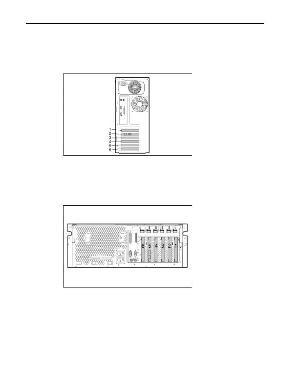
The ProLiant 8000 has 11 PCI slots: ten 64-Bit slots and one 32-Bit PCI slot (see Figure 4).
Figure 4. Slot view of the ProLiant 8000
Primary Bus:
Slot 1 is the first PCI slot
detected in this server
configuration. Bus
numbering starts here and
continues to slots 2, 3,
and 4.
Secondary Bus:
Bus numbering continues
down to slots 5, 6, 7, 8,
and 9.
Tertiary Bus:
Then, bus numbering
completes after reaching
slots 10 and 11.
ProLiant ML530
ProLiant ML530 contains a highly parallel bus and has 8 PCI slots: two 64-Bit 66MHz slots, five
64-Bit 33MHz slots, and one 32-Bit 33MHz slot (see Figure 5).
Figure 5. Slot view of the ProLiant ML530
Primary Bus:
Slot 1 comprises the
Primary Bus.
Secondary Bus:
Bus numbering continues
down level to slots 7 and
8.
Tertiary Bus:
Bus numbering continues
down level to slots 6, 4, 3,
and 2, completing after
assigning a bus number to
slot 5.
13UK-1200A-WWEN
Page 15
PCI Bus Numbering in a Microsoft Windows NT Environment 15
ProLiant ML350
ProLiant ML350 is a dual-peer bus and has 7 PCI slots: two 64-Bit 3V slots, four 32-Bit slots,
and one Non-Shared ISA slot (see Figure 6).
Primary Bus:
Bus numbering begins
on slot 1 and continues
to slots 4, 5, and 6.
Secondary Bus:
Slots 2 and 3 comprise
the Secondary Bus and
complete the bus
numbering in this
server configuration.
Figure 6. Slot view of the ProLiant ML350
ProLiant DL580
ProLiant DL580 is a triple-peer bus and is comprised of 6 PCI slots: two 64-Bit/66MHz slots,
three 64-Bit/33MHz slots, and one 32-Bit/33MHz slot (see Figure 7).
Figure 7. Slot view of ProLiant DL580
Primary Bus:
The Primary Bus
completes bus numbering
after assignment to 6.
Secondary Bus:
Bus numbering begins
with slot 1 and continues
to 2 and 3.
Tertiary Bus:
Bus numbering begins
with slot 4 and completes
with slot 5.
13UK-1200A-WWEN
Page 16
PCI Bus Numbering in a Microsoft Windows NT Environment 16
ProLiant DL380
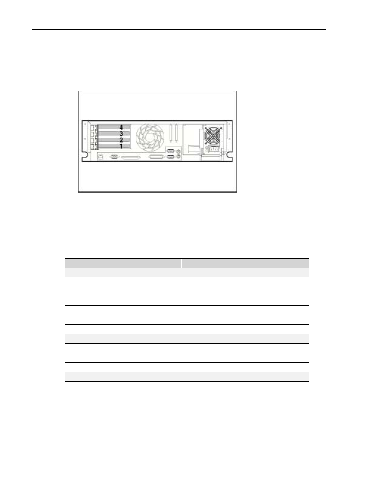
ProLiant DL380 contains a highly parallel bus and has 4 PCI slots: three 64-Bit slots and one 32Bit slot (see Figure 8).
Primary Bus:
Slot 1 is the only slot on
the Primary Bus.
Secondary Bus:
Slots 2, 3, and 4 complete
bus numbering on this
server configuration.
Figure 8. Slot view of the ProLiant DL380
Option Hardware
The following listing in Table 5 identifies the types of Compaq controllers that are categorized as
either PCI bridged or non-bridged.
Table 5. PCI bridged and no-bridged controllers
PCI Bridged Controllers Non-Bridged Controllers
Compaq Smart Array Controllers
RAID LC2 Controller Smart Array 5300 Controller
Smart Array 221 Controller Smart Array 4200 Controller
Smart Array 431 Controller Smart Array 3100ES Controller Smart Array 3200 Controller Smart Array 4250ES Controller -
Compaq SMART-2 Array Controllers
SMART-2SL Array Controller SMART-2 Array Controller SMART-2DH Array Controller -
Compaq SCSI Controllers
- Dual Channel Wide Ultra SCSI-2 Controller
- Dual Channel Wide-Ultra SCSI-3 Controller
- Wide-Ultra SCSI-3 Controller
continued
13UK-1200A-WWEN
Page 17

PCI Bus Numbering in a Microsoft Windows NT Environment 17
Table 5. PCI bridged and no-bridged controllers (continued)
PCI Bridged Controllers Non-Bridged Controllers
Compaq Fibre Channel Controllers
- Fibre Channel Host Controller
Compaq Network Interface Controllers
NC3122 Fast Ethernet NIC NC1120 Ethernet NIC
NC3131 10/100 Dual Port Modular Base NC3120 10/100 TX Fast Ethernet NIC
NC3134 Fast Ethernet NIC NC3121 Fast Ethernet NIC
Netelligent Dual 10/100 TX PCI UTP Controller NC3123 Fast Ethernet Net work Adapter PCI 10/100
- NC4621 Token Ring NIC
- NC6134 Gigabit NIC
- NetFlex-3 and Netelligent Controllers (excluding Dual
- NetFlex-3 and Netelligent Controllers (excluding Dual
Compaq Management Devices
Compaq Remote Insight Board/PCI Compaq Remote Insight Board Lights-Out
Edition
- Most Video Controllers
Wake-on-LAN
Port)
Port)
-
Other Devices
For a complete listing of supported controllers, visit the Compaq website:
• Network interface controllers, http://www.compaq.com/products/networking/nics/
• Storage controllers, http://www.compaq.com/products/servers/storage
Planning a PCI System Configuration
Modifying a multi-controller configuration and understanding what happens to specific physical
devices can be confusing in a PCI-based network server. Spending a little planning time up front
to become familiar with the server slot and bus configuration can prevent you from having to take
unnecessary time later trying to troubleshoot configuration mismatches. In many cases, it
completely prevents mismatches from occurring.
Note: PCI bus number assignment changes only
from the system.
Compaq recommends adding controllers to slots in the order in which the slots appear on the bus.
Following this recommendation prevents the occurrence of the scenarios discussed in the “PCI
Test Configurations with ProLiant Servers” section of this paper. Such occurrences are most
likely when controllers are added to an existing server configuration out of order, leaving
vacancies between slots that reside on the sam e bus.
if PCI bridge devices are added or removed
13UK-1200A-WWEN
Page 18

PCI Bus Numbering in a Microsoft Windows NT Environment 18
Before Modifying an Existing System
Complete a thorough planning session to understand possible considerations and anticipate
unexpected issues. Be sure to have a backup plan so you can return to your original configuration
if necessary.
Because bus renumbering is likely to occur when controllers are added or removed in a PCI
configuration, Compaq recommends that you perform the following steps:
• Backup the server registry and all data so that you can return to the original configuration,
if necessary.
• Update the Emergency Repair Disk so that you can use it to restore current system settings.
• Run the System Configuration Utility, from the System boot partition, and print out the log
that the utility generates. This log identifies slot numbers and bus number assignments.
• Log important network settings such as, protocols, IP addresses, frame types, etc.
When loading Disk Administrator
you will automatically be notified,
if a drive does not have a signature.
• Label the disk drives/volumes using the Windows NT Disk
Administrator. Drive letters remain the same, but disk number
assignment might change, including labels on disk helps
identification.
• Run Disk Administrator to verify that additional drives have received a signature from
Windows NT.
• Verify you have the necessary Windows NT CDs and the Compaq Support Paq for Microsoft
Windows NT 4.0 to update drivers, if necessary. This information will be essential should
you need to return to the original configuration.
Planning the New Configuration
The next part of the plan involves identifying the best method to update the original
configuration. Armed with the knowledge that PCI slot number and bus number assignments are
affected when controllers are added or removed will help you integrate new hardware into an
existing server configuration with minimal disruption and downtime.
You will also want to answer the following questions, before making modifications:
• Will the network controllers be standalone or set up as a redundant pair? Decide which slot(s)
to use for the NIC(s).
• What slots will be used for the disk controller(s)? Does the configuration include external
storage?
• Is the system load balanced across the buses to provide the optimal system performance?
• Does the controller(s) have a bridge? Controllers that contain bridges will be assigned a PCI
bus number which increments the bus numbering assignment of each subsequent PCI bridged
controller detected.
Reviewing these questions ahead of time will help you with the decision making process; each
computing environment differs and the responses to these questions will not be the same for
every configuration. You, as the network administrator, must determine the best solution for your
computing needs.
13UK-1200A-WWEN
Page 19

PCI Bus Numbering in a Microsoft Windows NT Environment 19
Step-By-Step Review
The Compaq Array Configuration
Utility can also be installed within
the Windows NT GUI after the
operating system is installed.
seated properly in the slots designated during the planning stage, before the server is powered
on.
• Gather all necessary operating system and support software.
• Load the Compaq Systems Configuration software on the server and install it on the system
partition of the hard drive. We used the following Compaq Systems Configuration software
testing and tracking tools to develop this white paper:
- System Configuration Utility - to configure the hardware and to view the slot and bus
number assignments before launching the Windows NT operating system.
- Drive Array Configuration Utility - to create disk arrays across multiple drives.
Note: Installing the System Configuration utilities on the server provides an easy way to
configure and verify hardware ins ta lla ti ons and m odificat ions to the sy stem in the future as
needed.
• Load the Compaq Support Paq (CSP) for Microsoft Windows NT 4.0 to ensure the system is
running with the latest driver enhancements. In addition to driver enhancements, the Compaq
Support Paq installs several important support utilities. The Compaq Support Paq runs a
detection process and identifies the software and utilities applicable to the installation.
Before beginning this process, Compaq recommends that you review your
configuration requirements and be prepared to answers the questions noted
earlier in the “Planning the New Configuration” section.
As with any installation:
• Verify all network and disk controllers included in the configuration are
PCI Test Configurations with ProLiant Servers
The following scenarios were tested in the Compaq Integration Lab. The scenarios demonstrate
how the PCI BIOS assigns the bus numbers and then reassigns the bus numbers after
configuration modifications. The following examples demonstrate the step-by-step changes that
occur:
Configurations A and B were also
performed using retired Compaq
ProLiant servers. These results are
detailed in Appendix A.
• Configuration C: Test 1 – Initial Configuration and Test 2 – Removing and Adding NICs Out
of Slot Order.
By understanding what configuration changes occur in the test scenarios described in this section,
you can better comprehend how PCI Bus numbers reassign when configuration changes occur in
your server. “Table 11. PCI Bus Number Order of Detection Matrix” included in this document
identifies the Controller Discovery Order for each of these servers and several others.
• Configuration A: Test 1 – Initial Configuration and Test 2 – Adding
a Device.
• Configuration B: Test 1 – Initial Configuration and Test 2 – Addition
of Two Controllers.
13UK-1200A-WWEN
Page 20

PCI Bus Numbering in a Microsoft Windows NT Environment 20
Configuration A, ProLiant ML530 (highly parallel architecture), a two configuration scenario:
This scenario walks through a simple Windows NT configuration and shows how the bus
numbers change when you add a new controller to the server. Two tables with a side bar
description of what the PCI BIOS does during the discovery process illustrate the configurations.
Configuration B, ProLiant 8000 (triple-peer architecture), a more complex two configuration
scenario: We modified the server to include additional disk and network controllers. Two tables
with a side bar description of what the PCI BIOS does during the discovery process illustrate the
configurations.
Configuration C, ProLiant DL580 (triple-peer architecture), another more complex scenario:
This demonstrates the slot ordering difference when additional network controllers are inserted
out of order in the configuration. Two tables with a side bar description of what the PCI BIOS
does during the discovery process illustrate the configurations.
Configuration A, ProLiant ML530
All the controllers included in this configuration were installed in the server before Windows NT
was loaded on the system. Windows NT detected network controllers in the original configuration
during the installation process. However, when the configuration is modified in Test 2, PCI bus
renumbering does occur.
Configuration A: Test 1 – Initial Configuration
This bus number and controller discovery test was performed on a simple configuration in a dualpeer PCI ProLiant ML530 server. This configuration is described as simple because it contains one
non-bridged PCI network controller and one bridged PCI network controller (see the results in
Table 6).
13UK-1200A-WWEN
Page 21

PCI Bus Numbering in a Microsoft Windows NT Environment 21
Note: Even though PCI bus numbers assign during every boot process, the number remains
exactly the same as long as the configuration remains the same.
Table 6. PCI BIOS bus detection in a ProLiant ML530–before adding a bridged controller
Bus
Detection
Order/
Controller
Discovery
1st
2nd
3rd
4th
5th
6th
7th
8th
th
9
10th
11th
Slot
Number
Primary
Bus (O)
Slot 1
Secondary
Bus (2)
Slot 7
Slot 8
Tertiary
Bus (5)
Slot 6
Slot 4
Slot 3
Slot 2
Slot 5
PCI Bridge/
Controller
Type – Test 1
Host to PCI
Bridge
Empty
Host to PCI
Bridge
Empty
Empty
Host to PCI
Bridge
Empty
Empty
Empty
Empty
NC3132 (nonbridged)
Bus Number
Assignment
Bus 0
N/A
Bus 2
N/A
N/A
Bus 5
N/A
N/A
N/A
N/A
Bus 5
Description of PCI BIOS Discovery
Process
The PCI BIOS discovers the Primary Bus
and assigns it bus 0.
Discovery process continues to PCI slot 1.
No PCI controller detected, no bus number
assigned.
The PCI BIOS discovers the Secondary
Bus and increments the bus number to 2.
Discovery process continues to PCI slot 7.
No PCI controller detected, no bus number
assigned.
Discovery process continues to PCI slot 8.
No PCI controller detected, no bus number
assigned.
The PCI BIOS discovers the Tertiary Bus
and increments the bus number to 5.
Discovery process continues to PCI slots
6, 4, 3, and 2. No PCI controller detected,
no bus number assigned.
PCI BIOS detects a NIC (no PCI bridge) in
slot 5, it is assigned the same bus number
as the PCI Bus where it resides, and is the
first controller detected by the PCI BIOS.
Reviewing the Test 1 Configuration
In Test 1, the PCI BIOS begins the discovery process by identifying buses on the Primary PCI
Bus, then continues to the Secondary PCI Bus looking for PCI buses and or bridges, and
completes after reaching the last slot on the Tertiary PCI bus. As each bus is detected it is
assigned a bus number starting at bus 0, the PCI BIOS then assigns bus numbers to the PCI
controllers discovered on each bus. In this example, the controllers do not contain bridges.
Therefore, they are assigned the same bus number as the bus on which they reside.
Note: Bus numbers (appear in boldface type in Table 6) are assigned during bus initialization
according to predefined hardware designators. The bus numbers may not appear to follow a set
increment and some numbers may be skipped. However, by this method, these hardware
designators prevent overlays in bus numbering from occurring.
13UK-1200A-WWEN
Page 22

PCI Bus Numbering in a Microsoft Windows NT Environment 22
Configuration A – Test 2 – Adding a Device
The example in Table 7 illustrates the PCI BIOS discovery and bus number assignment process in
the same ProLiant ML530 server. However, the configuration changes slightly by adding a
bridged PCI network controller on the Tertiary Bus.
Table 7. PCI BIOS bus detection in a ProLiant ML530–after adding a bridged controller
Bus
Detection
Order/
Controller
Discovery
1st
2nd
3rd
4th
5th
6th
7th
8th
th
9
10th
11th Slot 5 NC3132 (non-
*Bus number is different than previous configuration
Slot
Number
Primary
Bus (O)
Slot 1
Secondary
Bus (2)
Slot 7
Slot 8
Tertiary
Bus (5)
Slot 6
Slot 4
Slot 3
Slot 2
PCI Bridge/
Controller
Type – Test 1
Host to PCI
Bridge
Empty
Host to PCI
Bridge
Empty
Empty
Host to PCI
Bridge
NC3131
Empty
Empty
Empty
bridged)
Bus Number
Assignment
Bus 0
N/A
Bus 2
N/A
N/A
Bus 5
Bus 6
N/A
N/A
N/A
Bus 5
Description of PCI BIOS Discovery
Process
The PCI BIOS discovers the Primary Bus
and assigns it bus 0.
Discovery process continues to PCI slot 1.
No PCI controller detected, no bus number
assigned.
The PCI BIOS discovers the Secondary
Bus and increments the bus number to 2.
Discovery process continues to PCI slots 7
and 8. No PCI controller detected, no bus
number assigned.
The PCI BIOS discovers the Tertiary Bus
and increments the bus number to 5.
Discovery process continues to PCI slot 6,
and detects a bridged NIC, incrementing
the bus number by one to become bus 6.
Discovery process continues to PCI slots
4, 3, and 2. No PCI controller detected, no
bus number assigned.
PCI BIOS detects a NIC (no PCI bridge) in
slot 5, it is assigned the same bus number
as the PCI Bus where it resides.
13UK-1200A-WWEN
Page 23

PCI Bus Numbering in a Microsoft Windows NT Environment 23
Reviewing the Test 2 Configuration
In Test 2, as in Test 1, the PCI BIOS begins the discovery process by identifying buses on the
Primary PCI Bus, which is assigned bus 0. Slot 6 on the Tertiary Bus now contains a NC3131
Fast Ethernet NIC (a bridged controller), which increments the bus number assignment to bus 6.
The network controller in slot 5 is also assigned bus 5 as it was before.
At this point, Windows NT is not aware that the bus number assignments have changed. The
bindings for the network controller in slot 6 are no longer applicable and must be manually reset
for this controller to function in the configuration again. Refer to the “Compaq Network and
Teaming Configuration Utility” section in this document for instructions on how to reset the
bindings.
Comparison of Test 1 to Test 2 - Configuration A
When you reboot the server and run the System Configuration utility to view the hardware
configuration changes, it displays slot and bus number assignments. Test 2 data was recorded and
compared to Test 1.
A side-by-side comparison of the slot configurations and bus numbers of each device in Test 1 to
the slot configurations and bus numbers of each device in Test 2, illustrates what bus numbers
were changed after modifications took place.
Slot Type Controller Test 1 Test 2 Bus Assignment
Slot 1 Empty N/A
Slot 2 Empty N/A
Slot 3 Empty N/A
Slot 4 Empty N/A
Slot 5 NC3123 (non-bridged) $ $ Bus 5 – No Change
Slot 6 NC3131 (bridged) $ Bus 6 – New
Slot 7 Empty N/A
Slot 8 Empty N/A
Configuration B, ProLiant 8000
Configuration B included two installations tested on the ProLiant 8000. The test 1 server was set
up as an original Window NT server configuration. All the controllers included in this
configuration were installed in the server before Windows NT was loaded on the system. Because
they were a part of the original configuration, Windows NT detected the network controllers
during the installation process. However, when additional controllers are later added to the
system in a modified configuration, PCI bus renumbering does occur. The information that
follows in this section explains these changes as they occur and how you can easily modify
Windows NT with several Compaq and Windows NT utilities.
13UK-1200A-WWEN
Page 24

PCI Bus Numbering in a Microsoft Windows NT Environment 24
The diagrams in Figure 9 illustrate the location of the expansion slots in the rear of the ProLiant
8000.
321 4 5 6 7 8 9 10 11
Figure 9. Location of expansion slots in the ProLiant 8000
Bus number assignments for
controllers with bridged devices
are assigned to the device on the
controller.
Table 8 illustrates the relati onship between slo t num bers, cont rol ler
installation, and PCI BIOS bus assignments in Configuration B–Test 1.
This test includes several bridged controllers to demonstrate bus
renumbering in a more complex configuration.
13UK-1200A-WWEN
Page 25

PCI Bus Numbering in a Microsoft Windows NT Environment 25
Table 8. Test 1 – PCI BIOS bus detection in the ProLiant 8000
Bus
Detection
Order/
Controller
Discovery
1st
2nd
3rd
4th
5th
6th
7th
8th
9th
10th
11th
12th
13th
14th
Slot
Number
Primary
Bus (O)
Slot 1
Slot 2
Slot 3
Slot 4
Secondary
Bus (6)
Slot 5
Slot 6
Slot 7
Slot 8
Tertiary
Bus (13)
Slot 9
Slot 10
Slot 11
PCI Bridge/
Controller Type
- Test 1
Host to PCI
Bridge
Empty
Empty
Empty
Empty
Host to PCI
Bridge
NC3131
Empty
Empty
Empty
Host to PCI
Bridge
Empty
Empty
Smart Array
4250ES
Bus Number
Assignment
Bus 0
N/A
N/A
N/A
N/A
Bus 6
Bus 7
N/A
N/A
N/A
Bus 13
N/A
N/A
Bus 14
Description of PCI BIOS
Discovery Process
The PCI BIOS assigns 0 to
the Primary Bus and
continues downstream with
the controller discovery.
Slots 1-4 are empty, no PCI
bus number assignment.
The PCI BIOS discovers the
Secondary Bus and assigns it
bus number 6.
NIC in slot 5 contains a PCI
bridge and the PCI BIOS
increments the PCI bus
number to 7.
Slots 6-8 are empty, no PCI
bus number assignment.
The PCI BIOS discovers the
Tertiary Bus and assigns it
bus number 13.
Slots 9 and 10 are empty, no
PCI bus number assignment.
Intelligent drive array
controller with PCI bridge is
detected in slot 11. The PCI
BIOS increments the PCI
number to bus 14 and assigns
it to the bridge on the
controller.
Reviewing the Test 1 Configuration – Initial Configuration
Configuration B−Test 1, illustrated in Table 8, provides an example of how the PCI BIOS
discovers controller devices and assigns bus numbers during the discovery process. As the PCI
BIOS moves through the bus detection order it looks for controller devices (not the slot numbers).
In this example, the PCI BIOS begins at the Host Bus and moves downstream assigning bus
numbers starting at bus 0 on the Primary Bus. In this scenario, no PCI devices reside on the
Primary bus, so the discovery process continues to the Secondary Bus by assigning 6 as the bus
number. The NC3131 in slot 5, a bridged device, is discovered next. The PCI BIOS assigns bus 7
to the PCI bus on the bridged controller, the last PCI controller discovered on the Secondary Bus.
13UK-1200A-WWEN
Page 26

PCI Bus Numbering in a Microsoft Windows NT Environment 26
At this point, the PCI BIOS discovery process continues to the Tertiary Bus where it increments
the bus assignment to 13. The Smart Array 4250ES Controller in slot 11 is assigned bus 14 since
it is a bridged device.
Test 2 in Table 9 illustrates how bus assignments change when physical configuration changes
occur in the server.
IMPORTANT: The controllers that our testing added to the server configuration were selected
only to illustrate how bus renumbering occurs. Several different Smart Array and network
controllers were included to demonstrate that they all respond to renumbering in the same
manner. This is not meant to be a recommended configuration.
13UK-1200A-WWEN
Page 27

PCI Bus Numbering in a Microsoft Windows NT Environment 27
Table 9: Test 2 – PCI BIOS bus detection in the ProLiant 8000
Bus
Detection
Order/
Controller
Discovery
1st
2nd
3rd
4th
5th
6th
7th
8th
9th
10th
11th
12th
13th
14th
*Bus number is different than previous configuration.
Slot Number PCI Bridge/
Primary Bus
(O)
Slot 1
Slot 2
Slot 3
Slot 4
Secondary
Bus (6)
Slot 5
Slot 6
Slot 7
Slot 8
Tertiary Bus
(13)
Slot 9
Slot 10
Slot 11
Controller
Type - Test 2
Host to PCI
Bridge
Empty
NC3131
Empty
Empty
Host to PCI
Bridge
NC3131
Empty
Empty
Empty
Host to PCI
Bridge
Empty
Smart Array
4250ES
Smart Array
4250ES
Bus Number
Assignment
Bus 0
N/A
Bus 1
N/A
N/A
Bus 6
Bus 7
N/A
N/A
N/A
Bus 13
N/A
Bus 14
Bus 15
Description of PCI BIOS Discovery
Process
The PCI BIOS assigns 0 to the Primary
Bus and continues downstream with
the controller discovery.
Slot 1 is empty, no PCI bus number
assignment.
NIC in slot 2 contains a PCI bridge and
the PCI BIOS increments the PCI bus
number to 1.
Slots 3 and 4 are empty, no PCI bus
number assignment.
The PCI BIOS discovers the
Secondary Bus and assigns it bus
number 6.
NIC in slot 5 contains a PCI bridge and
the PCI BIOS increments the PCI bus
number to 7.
Slots 6-8 are empty, no PCI bus
number assignment.
The PCI BIOS discovers the Tertiary
Bus and assigns it bus number 13.
Slot 9 is empty, no PCI bus number
assignment.
Intelligent drive array controller with
PCI bridge is detected in slot 10. The
PCI BIOS increments the PCI numbe r
to bus 14 and assigns it to the bridge
on the controller.
Slot 11 also contains a bridged array
controller, changing its original bus
number from bus 14 to bus 15.
13UK-1200A-WWEN
Page 28

PCI Bus Numbering in a Microsoft Windows NT Environment 28
Reviewing the Test 2 Configuration – Addition of Two Controllers
Configuration B−Test 2, illustrated in Table 9, provides an example of how the PCI BIOS
discovers new controller devices not present in the original Test 1 configuration and how it
assigns bus numbers during the discovery process. As in Test 1, the PCI BIOS moves through the
bus detection order looking for controller devices (not slot numbers). In this example, the PCI
BIOS begins at the Host Bus and assigns bus 0 to the Primary Bus. The PCI BIOS continues to
search for the next device downstream on the Primary Bus. One bridged controller was added to
the configuration on the Primary Bus. Upon discovery of each controller, the PCI BIOS assigns a
bus number to the PCI bus on the bridged controller. Slot 2 now contains a NC3131 Fast Ethernet
NIC on bus 1. Since slot 2 contained the last PCI device on the Primary Bus, the discovery
process continues to the Secondary Bus.
The Secondary Bus is assigned a bus number of 6. The NC3131 Fast Ethernet NIC in slot 5, a
bridged device, is discovered next. The PCI BIOS assigns bus 7 to the PCI bus on the controller,
the last PCI controller discovered on the Secondary Bus.
The Tertiary Bus is assigned bus 13. The controllers downstream on the Tertiary Bus in slots 10
and 11 both contain bridges. Bus number assignments are made to the PCI buses on these bridged
controllers. The Smart Array 4250ES Controller in slot 10 is assigned bus 14 and the Smart Array
4250ES Controller in slot 11 incremented to bus 15. Empty slots are ignored, because they do not
contain PCI devices.
Comparison of Test 1 to Test 2 - Configuration B
When you reboot the server and run the System Configuration utility to view the hardware
configuration changes, it displays slot and bus number assignments. Test 2 data was recorded and
compared to Test 1.
A side-by-side comparison of the slot configurations and bus numbers of each device in Test 1 to
the slot configurations and bus numbers of each device in Test 2, illustrates what bus numbers
were changed after modifications took place.
Slot Controller Test 1 Test 2 Bus Assignment
Slot 1 Empty N/A
Slot 2 NC3131 (bridged) $ Bus 1 - New
Slot 3 Empty N/A
Slot 4 Empty N/A
Slot 5 NC3131 (bridged) $ $ Bus 7 – No Change
Slot 9 Empty N/A
Slot 7 Empty N/A
Slot 9 Empty N/A
Slot 9 Empty N/A
Slot 10 Smart Array 4250ES (bridged) $ Bus 14 – New
Slot 10 Smart Array 4250ES (bridged) $ $ Bus 14 to 15 – Changed
13UK-1200A-WWEN
Page 29

PCI Bus Numbering in a Microsoft Windows NT Environment 29
Configuration C, ProLiant DL580
Table 10 is an example of a ProLiant DL580 server set up as an original Window NT server
configuration. All the controllers included in this configuration were installed in the server before
Windows NT was loaded on the system. Windows NT detected network controllers in the
original configuration (see Table 10) during the installation process. However, when the
configuration is modified in Test 2 (see Table 11), PCI bus renumbering does occur.
Configuration C: Test 1 – Initial Configuration
Table 10. PCI BIOS bus detection in a ProLiant DL580–before removing and inserting NICs
Bus
Detection
Order/
Controller
Discovery
1st
2nd
3rd
4th
5th
6th
7th
8th
9th
Slot
Number
Primary
Bus (0)
Slot 6
Secondary
Bus (2)
Slot 1
Slot 2
Slot 3
Tertiary
Bus (7)
Slot 4
Slot 5
PCI Bridge/
Controller Type
- Test 1
Host to PCI
Bridge
Empty
Host to PCI
Bridge
NC3131(bridged) Bus 3
Empty
NC3131
(bridged)
Host to PCI
Bridge
Empty
Empty
Bus Number
Assignment
Bus 0
N/A
Bus 2
N/A
Bus 4
Bus 7
N/A
N/A
Description of PCI BIOS
Discovery Process
The PCI BIOS assigns 0 to the
Primary Bus and continues
downstream with the controller
discovery.
Slot 6 is empty, no PCI bus number
assignment.
The PCI BIOS discovers the
Secondary Bus and assigns it bus
number 2.
NIC in slot 1 contains a PCI bridge
and the PCI BIOS increments the
PCI bus number to 3.
Slot 2 is empty, no PCI bus number
assignment.
Slot 3 contains a bridged NIC and
assumes a bus number of 4.
Finally, detection and assignment of
the Tertiary Bus occurs,
incrementing to 7.
Since both slots on the Tertiary Bus
are empty, a PCI bus number
assignment does not occur for these
slots.
Reviewing the Test 1 Configuration
Configuration C−Test 1, illustrated in Table 10, provides an example of how the PCI BIOS
discovers controller devices and assigns bus numbers during the discovery process. As the PCI
BIOS moves through the bus detection order it looks for controller devices (not the slot numbers).
In this example, the PCI BIOS begins at the Host Bus and moves downstream assigning bus
numbers starting at bus 0 on the Primary Bus. In this scenario, no PCI devices reside on the
Primary bus, so the discovery process continues to the Secondary Bus and assigns 2 as the bus
number. The NC3131 Fast Ethernet NIC is the first device detected. Since this controller contains
a PCI bridge, the bus number increments to 3. Slot 2 contains no device, so no bus number
13UK-1200A-WWEN
Page 30

PCI Bus Numbering in a Microsoft Windows NT Environment 30
assignment occurs. The NC3131 Fast Ethernet NIC (a bridged device), residing in slot 3,
increments the bus number. The discovery process completes with the discovery of the Tertiary
Bus, assigning a bus number of 7. Since slots 4 and 5 comprising the Tertiary Bus are empty, no
bus number assignment occurs for these slots.
IMPORTANT: The controllers added to the server configuration in our tests were selected only
to illustrate how bus renumbering occurs. This example is not meant to be a recommended
configuration.
Configuration A – Test 2 – Removing and Adding NICs
The example in Table 11 illustrates the PCI BIOS discovery and bus number assignment process
in the same ProLiant DL580 server, resulting in the reordering of bus numbers from the original
configuration. When adding new network interface controllers (NIC) to a server, the slot used to
input the device is significant since network connectivity can be lost for existing NICs in lower
numbered slots. Fortunately, this state is only temporary because the NIC driver must be
reconfigured to accommodate the new NIC, at which time the bindings for the other NICs will be
rebuilt.
Table 11. PCI BIOS bus detection in a ProLiant DL580–after removing and adding NICs
Bus
Detection
Order/
Controller
Discovery
1st
2nd
3rd
4th
5th
6th
7th
8th
9th
*Bus number is different than previous configuration
Slot
Number
Primary
Bus (0)
Slot 6
Secondary
Bus (2)
Slot 1
Slot 2
Slot 3
Tertiary
Bus (7)
Slot 4
Slot 5
PCI Bridge/
Controller Type
- Test 1
Host to PCI
Bridge
Empty
Host to PCI
Bridge
NC3131(bridged) Bus 3
NC3131(bridged) Bus 4
NC3131(bridged) Bus 5*
Host to PCI
Bridge
Empty
Empty
Bus Number
Assignment
Bus 0
N/A
Bus 2
Bus 7
N/A
N/A
Description of PCI BIOS
Discovery Process
The PCI BIOS assigns 0 to the
Primary Bus and continues
downstream with the controller
discovery.
Slot 6 is empty, no PCI bus number
assignment.
The PCI BIOS discovers the
Secondary Bus and assigns it bus
number 2.
NIC in slot 1 contains a PCI bridge
and the PCI BIOS increments the
PCI bus number to 3.
Slot 2 also contains a PCI bridge,
making its PCI bus number
assignment 4.
Slot 3 contains a bridged NIC and
assumes a bus number of 5.
Finally, detection and assignment of
the Tertiary Bus occurs,
incrementing to 7.
Since both slots on the Tertiary Bus
are empty, a PCI bus number
assignment does not occur for these
slots.
13UK-1200A-WWEN
Page 31

PCI Bus Numbering in a Microsoft Windows NT Environment 31
Reviewing the Test 2 Configuration
Windows NT enumerates the NIC instances on the PCI bus from the highest numbered slot to the
lowest numbered slot. The bindings for each instantiation of the NIC drivers are dependent upon
the PCI bus number of each NIC. Installation of a NIC in a slot between two NICs previously
installed and configured in Windows NT can result in the loss of the network bindings of NICs in
the lower numbered slots. However, this loss of bindings will only be a problem until the NIC
driver is installed and bound to the NIC ports, which is required any time a new NIC is installed
in a system.
In this scenario, installing the NC3131 Fast Ethernet NIC, a bridged device, in slot 2 caused the
newly installed NIC to assume the driver instance and bindings of the NIC installed in slot 3.
Now, the NICs in slots 1 and 2 are bound to one another, leaving the NIC in slot 3 unbound until
it is manually reconfigured. Note that only NICs inserted between NICs affect network bindings.
Comparison of Test 1 to Test 2 - Configuration C
When you reboot the server and run the System Configuration utility to view the hardware
configuration changes, it displays slot and bus number assignments.
A side-by-side comparison of the slot configurations and bus numbers of each device in Test 1 to
the slot configurations and bus numbers of each device in Test 2, illustrates what bus numbers
were changed after modifications took place.
Slot Type Controller Test 1 Test 2 Bus Assignment
Slot 1 NC3131 (bridged) $ $ B us 3 – No Change
Slot 2 NC3131 (bridged) $ Bus 4 – No Change
Slot 3 NC3131 (bridged) $ $ B us 4 to 5 - Change
Slot 4 Empty N/A
Slot 5 Empty N/A
Slot 6 Empty N/A
Updating the Server After the Configuration Changes
The server configuration now includes three network controllers. The controllers in slot 1
(original in Test 1), slot 2 (added in Test 2), and slot 3 (original in Test 1) are network control lers.
These controllers must be reconfigured when the operating system is brought back up or they will
not function. As stated earlier in this document, Windows NT records PCI controllers and bus
numbers in the registry, but it does not automatically update the registry when the system is
physically modified. Due to the nature of the PCI bus enumeration algorithm, removing a bridged
PCI device might cause the bus numbers of other PCI devices to change. This change in no way
affects your data or your applications.
Rules of Thumb Before Adding More Controllers to a Server
In Test 2 several controllers are added to the system to provide additional support in
Configuration C. This test configuration illustrates how PCI bus numbers are reassigned based on
the reordered controllers in the server.
13UK-1200A-WWEN
Page 32

PCI Bus Numbering in a Microsoft Windows NT Environment 32
Keep in mind, the following certain rules of thumb:
• Single port devices are generally not bridged and assume the bus number of the bus on which
they reside. However, the SMART-2/SL Drive Array Controller is an exception to the rule
(see next bullet); it is a single-port intelligent bridged disk device.
• Multiple port (dual network NICs) and intelligent devices (SMART-2 Controllers and Smart
Array Controllers) often contain bridges and receive a bus number assignment for each PCI
bus.
During this process, complete the fol low ing :
• Do not place all network controllers on the same bus, and do not place all disk controllers on
the same bus. Balance the load between buses for optimal performance.
• Record all important network settings and numbers before you make changes (protocols,
frame types, IP addresses, etc).
• Run the Disk Administrator after Windows NT installation to ensure that the boot drive
receives a signature properly (Drive C:). Use the Disk Administrator to label disk controllers
in case the disks become renumbered in the new configuration. Systems with a large disk
expansion base can be hard to sort out without labels.
• Determine what tools to use ahead of time for resetting the system should the need occur.
Reestablishing Network Connections
The following section describes how the various Compaq and Windows NT utilities can provide
assistance in verifying connections and reestablishing network links. Again, this is not a complete
list of tools, but the ones that our testing found the most helpful.
Compaq Network Teaming and Configuration Utility
The Compaq Network Teaming and Configuration Utility is the Microsoft Windows NT 4.0
application for configuring Compaq 10/100 and Gigabit NICs.
Note: If your server contains a TLAN-based network controller, you must use the Compaq
TLAN Teaming and Configuration Utility referenced in Appendix C.
The applet for this utility can be found in the Windows NT Control Panel with an icon labeled
Compaq Network. This utility installs from the Compaq Support Paq for Microsoft Windows NT
4.0, if the system contains Compaq network controllers based on Intel technology.
This utility supports the following controllers:
• Compaq NC1120 Ethernet NIC
• Compaq NC3120 Fast Ethernet NIC (PCI 10/100)
• Compaq NC3121 Fast Ethernet NIC (PCI 10/100 WOL)
• Compaq NC3122 Fast Ethernet NIC (PCI Dual 10/100) (82558 )
• Compaq NC3123 Fast Ethernet NIC (82559 )
• Compaq NC3131 Fast Ethernet NIC (Dual Base 10/100) (82558)
13UK-1200A-WWEN
Page 33

PCI Bus Numbering in a Microsoft Windows NT Environment 33
• Compaq NC3132 Fast Ethernet Upgrade Module (Dual 10/100) for NC3131 and NC3134
Server NICs (82558)
• Compaq NC3133 100FX Upgrade Module for NC3131 and NC3134 Server NICs
• Compaq NC3134 Fast Ethernet Server NIC (82559)
• Compaq NC3135 Fast Ethernet Upgrade Module for NC3131 and NC3134 Server NICs
(82559)
• Compaq NC3160 Upgrade Module for NC3131 and NC3134 Server NICs (82559)
• Compaq NC3160 Fast Ethernet NIC
• Compaq NC3161 Fast Ethernet NIC
• Compaq NC6132 1000 SX Gigabit Upgrade Module for NC3131 and NC3134 Server NICs
• Compaq NC6133 1000 LX Gigabit Upgrade Module for NC3131 and NC3134 Server NICs
• Compaq NC6134 Gigabit NIC (PCI 1000 SX)
The procedures that follow describe how to install and uninstall network controllers using the
Compaq Network Teaming and Configuration Utility. The features discussed here do not describe
all the capabilities of this utility. The configuration in Configuration C−Test 2 must be
reconfigured in Windows NT after several new controllers are added to the ProLiant DL580
server. The following section illustrates how to reconfigure a controller(s).
Main Window:
Each Compaq Ethernet, Fast Ethernet, or Gigabit network controller that you install as standalone
must have a separate driver instance in Microsoft Windows NT. If any unbound services exist,
the Compaq Network Teaming and Configuration Utility detects them when the utility starts and
displays the status of each. Here are some reasons why you would see these results:
• You physically removed a controller and did not uninstall it first.
• You physically moved an installed controller to another slot without uninstalling it first.
• You physically removed or added a bridged PCI controller.
The following procedures describe how to configure bindings that became unbound due to one of
the above mentioned reasons.
After the network controllers were modified in Configuration C and the Compaq Network
Teaming and Configuration Utility is accessed:
1. Select Start →→→→ Settings →→→→ Control Panel.
2. Select the Compaq Network icon to launch the Compaq Network Teaming and
Configuration Utility. Figure 10 shows the controllers requiring reconfiguration in
Configuration C.
13UK-1200A-WWEN
Page 34

PCI Bus Numbering in a Microsoft Windows NT Environment 34
Figure 10. NICs in configuration c – test 2 before being reconfigured
Uninstalling and/or Installing a Standalone Controller
Here are the steps to follow to install and uninstall controllers. To install and uninstall network
controllers that are configured as standalone, fo llow the se steps:
Uninstalling a Controller:
1. Double click Start →→→→ Settings →→→→ Control Panel.
2. Select the Compaq Network icon to launch the Network Teaming and Configuration Utility.
a. Highlight the controller that did not load (no other controllers should be selected).
b. Click the Uninstall option.
3. Select the Close button when finished.
This will immediately uninstall the controller (i.e., remove its entries from the registry). The
driver for this adapter will not be removed from memory until the system is restarted.
Installing a Controller:
1. Double-click Start →→→→ Settings →→→→ Control Panel.
a. Highlight the uninstalled controller you want to install (no other controllers should be
selected).
b. Select the Install option.
2. Select the Close button when finished.
Once the installation completes, the controller turns yellow. This indicates that the registry
contains the controller, but the driver is not currently loaded in memory (the driver loads the next
time the system restarts). All installed controllers have a number in brackets next to their name.
This is the network card number for that driver instance. You must restart the server for the
changes to take effect.
13UK-1200A-WWEN
Page 35

PCI Bus Numbering in a Microsoft Windows NT Environment 35
After the computer restarts, Figure 11 shows that the computer, the slot, and the bus number
information agree with the Configura tion C results:
• Slot 1 contains a NC3131 Fast Ethernet NIC on Bus 3.
• Slot 2 contains a NC3131 Fast Ethernet NIC on Bus 4.
• Slot 3 contains a NC3131 Fast Ethernet NIC on Bus 5.
Figure 11. NICs in configuration c–test 2 after being reconfigured
Configuring Other Manufacturer’s Network Controllers with the Network Applet
If your server includes other manufacturer’s network controllers, perform the following steps to
reset the controller:
1. Double-click the Network icon, in the Windows NT Control Panel, and record pertinent
information for all control lers in the server.
2. Highlight the controller that did not load and select the Remove option.
Note: The Remove and Add steps are a manual process and must be performed separately.
3. Re-add the controller by selecting the controller from the Adapter List and then select
Continue.
4. Enter the controller information recorded (IP address, etc.) in the Network Settings dialog
box.
5. Shut down and restart the server when the network controller conf ig uration completes.
When configuration changes are m ade affec ting other manufacturer’s controlle rs, the Com paq
Network Teaming and configuration Utility to reestablish bindings (required when the controller
receives a new bus number because of modifications).
13UK-1200A-WWEN
Page 36

PCI Bus Numbering in a Microsoft Windows NT Environment 36
Compaq Support Software and Utilities
This section provides a brief review of several of the Compaq support software utilities used as
test and configuration tools to develop this white paper.
Compaq Systems Configuration Utility
The Compaq Systems Configuration Utility, a tool used to configure Compaq servers, runs
each time you change the physical hardware of an opti onal component in the server. It
displays the physical slot number for each installed controller board and, in most cases, the
bus number. You can find it on the Compaq SmartStart and Support Software CD and on the
Compaq website at http://www.compaq.com/support/files/server/us/index.html
Compaq Support Paq (CSP) for Microsoft Windows NT 4.0
The Compaq Support Paq (CSP) for Microsoft Windows NT 4.0 provides driver and software
utilities to support value-added features on Compaq servers. Several of the utilities and
drivers discussed in this document include features that support PCI bus numbering.
Discussion relative to the Compaq Support Paq feature set is limited to the scope of this
document. This software is available on the Compaq SmartStart and Support Software CD
and on the Compaq website at http://www.compaq.com/support/files/server/us/index.html
.
.
Compaq PCI Hot Plug Utility
The Compaq PCI Hot Plug Utility provides a common point for managing the PCI Hot Plug
buses on the local system, as well as remote systems accessible over the network. Compaq
PCI Hot Plug software for Windows NT includes hot-plug aware device drivers, operating
system support, and the PCI Hot Plug Utility. The PCI Hot Plug Utility graphically provides
a method of identifying slot and controller installation and bus number assignment. Hot plug
aware device drivers enable the system to halt operations on a specific controller prior to
removing the controller.
The Compaq PCI Hot Plug Utility is part of the Compaq Support Paq, which can be obtained
from the Compaq SmartStart and Support Software CD and on the Compaq website at
http://www.compaq.com/support/files/server/us/index.html
. Once installed, the utility appears
as the Compaq PCI Hot Plug applet under Control Panel, as well as appearing in the screen,
as shown in a special Compaq System Tools folder. A complete description of all the
capabilities and features of this utility are documented in the Deploying PCI Hot Plug on
Compaq Servers in a Microsoft Windows NT Environment, July 1997 - Doc ID 064A/0797
white paper.
Compaq Array Configuration Utility
The Compaq Array Configuration Utility configures SMART-2 Array and Smart Array
controllers. It also provides a view of the disk numbers that Windows NT assigns to drive
arrays and disk volumes. Once installed, the utility appears under Programs in the Compaq
System Tools folder. This utility is available from within the system boot partition as a
selection in the Systems Configuration utilities. It is also an installation option as a GUI tool
with the Compaq Support Paq when drive arrays are detected on the server.
13UK-1200A-WWEN
Page 37

PCI Bus Numbering in a Microsoft Windows NT Environment 37
The Compaq Array Configuration Utility is packaged as a Smart Component and as part of
the Compaq Support Paq, which may be found at the following locations:
• Compaq SmartStart and Support Software CD
(http://www.compaq.com/support/files/server/us/smartstart.html
)
• Compaq Server Software Download Center website
(http://www.compaq.com/support/files/server/us/index.html
)
Compaq Network Teaming and Configuration Utility
This network-monitoring tool allows you to install, uninstall, configure and monitor Compaq
10/100 and Gigabit adapters. This utility also displays and provides a method of updating PCI
bus number assignments, bus type, and slot numbers associated with each device. A complete
description of all the capabilities and features of this utility are documented in the utility Help
file. This utility is packaged in the Smart Component called Compaq Ethernet/Fast Ethernet
or Gigabit NIC Driver for Windows NT 4.0, available as an individual component and within
the Compaq Support Paq for Microsoft Windows NT 4.0, on the Compaq SmartStart and
Support Software CD and on the Compaq website at
http://www.compaq.com/support/files/server/us/index.html
.
For retired Compaq servers, refer to the “Compaq TLAN Teaming and Configuration Utility”
section in Appendix C.
Compaq Survey Utility for Windows
This utility contains an online agent that captures critical hardware and operating system
configuration information on Compaq servers without interrupting server operation. It
automates a configuration history log, allowing administrators to identify and compare
configuration changes. This utility also details PCI device number and slot number
assignments.
This utility provides a survey of the
system on a periodic basis and
provides printable history file
called survey.txt. You can use it to
identify changes to the system.
Refer to the Readme.txt file for
detail information about using this
utility.
recorded and available when needed. You can modify the data-gathering interval by
modifying the command line parameters. The Compaq Survey Utility allows you to resolve
problems without taking the server offline and to assist in maximizing server availability.
This utility downloads as an individual Smart Component or as part of the Compaq Support
Paq for Microsoft Windows NT 4.0 via the Compaq website at
http://www.compaq.com/support/files/server/us/index.htmlhttp://www.compaq.com/support/f
iles/server/MGMTSOL/index.html. It can also be installed from the Compaq Integration
Maintenance Utility, if you set up your server with the Compaq SmartStart and Support
Software CD and the Compaq Management CD.
The information the Survey Utility gathers is accessible locally at the
host server console. From the console you can view the Survey Utility
file online, get an updated snapshot of a server’s configuration, and
generate new output files. The Survey Utility outputs the information it
gathers into SURVEY.TXT. This file is located in [Windows NT
Drive]:\COMPAQ\SURVEY for Windows NT. The Survey Utility is
normally installed to run at startup and at specif ied time intervals. This
helps to ensure that the latest information and change history is always
13UK-1200A-WWEN
Page 38

PCI Bus Numbering in a Microsoft Windows NT Environment 38
Windows NT Disk Administrator
Disk Administrator, a graphical tool for managing disks, provides status information about disks,
such as the partition sizes and the amount of free space available for creating additional partitions.
It also includes status information, such as the disk number assignment, drive-letter assignment,
volume label, file system type, and size.
The illustration in Figure 12 illustrates how labels can assist you to identify drives and volumes in
the server. Without labels, the disk can only be identified by the drive letter.
IMPORTANT: Compaq strongly recommends that you label disks and volumes with
meaningful labels.
Sometimes due to configuration changes, Windows NT reorders the disk drives. Drives and
volumes that contain descriptive labels can more readily be identified when the system is brought
back on line. This might not be a problem in small server configurations; however, as a network
grows with more drives and volumes added, drive identification could become difficult, if not
impossible, to monitor.
Figure 12. Including disk labeling in a server configuration
13UK-1200A-WWEN
Page 39

PCI Bus Numbering in a Microsoft Windows NT Environment 39
Additional Troubleshooting Tips
Table 11 lists the PCI bus detection order, Primary and Secondary bus locations, and slot
numbers for the several ProLiant servers. This matrix can help you identify how the PCI BIOS
assigns bus numbers in these servers. The ProLiant 8000 and ProLiant DL580 include triple-peer
PCI Bus architecture, the ProLiant ML530 and ProLiant DL380 contain highly parallel PCI Bus
architecture, and the ProLiant ML350 is a dual-peer PCI Bus architecture server. This matrix
illustrates the differences in the PCI bus number detection order from one server model to
another.
Table 12. PCI Bus Number Order of Detection Matrix
Bus Triple-Peer PCI Buses Highly Parallel PCI Buses Dual-Peer PCI
Detect/
Order
Controller
Discovery
1st
2nd Slot 6 –
3rd
4th Slot 1 -
5th Slot 2 -
6th Slot 3 -
7th
8th Slot 4 –
9th Slot 5 –
10th Slot 8 -
11th Slot 9 -
12th
13th Slot 10 –
14th Slot 11 –
ProLiant
DL580
Primary
Host to PCI
Bridge
Pri Bus
Secondary
Host to PCI
Bridge
Sec Bus
Sec Bus
Sec Bus
Tertiary
Host to PCI
Bridge
Ter Bus
Ter Bus
Tertiary
ProLiant
8000
Primary
Host to PCI
Bridge
Slot 1 Pri Bus
Slot 2 Pri Bus
Slot 3 Pri Bus
Slot 4 Pri Bus
Secondary
Host to PCI
Bridge
Slot 5 –
Sec Bus
Slot 6 –
Sec Bus
Slot 7 –
Sec Bus
Sec Bus
Sec Bus
Host to PCI
Bridge
Ter Bus
Ter Bus
ProLiant
DL380
Primary Host to
PCI Bridge
Slot 1 - Pri Bus Slot 1 - Pri Bus Slot 1 - Pri Bus
Secondary Host to
PCI Bridge
Slot 2 - Sec Bus Slot 7 - Sec Bus Slot 5 - Pri Bus
Slot 3 - Sec Bus Slot 8 - Sec Bus Slot 6 - Pri Bus
Slot 4 - Sec
Bus
Slot 6 - Ter Bus Slot 2 - Sec Bus
Slot 4 - Ter Bus Slot 3 - Sec Bus
Slot 2 – Ter
Slot 5 – Ter
ProLiant
ML530
Primary Host to
PCI Bridge
Secondary Host to
PCI Bridge
Tertiary Host to
PCI Bridge
Slot 3 - Ter Bus
Bus
Bus
Buses
ProLiant
ML350
Primary Host to
PCI Bridge
Slot 4 - Pri Bus
Secondary Host to
PCI Bridge
In addition to this matrix, there is a PCI Bus Numbering HTML calculation tool for each server in
Table 11. You can access these tools on the Internet by going to the Compaq and Microsoft
13UK-1200A-WWEN
Page 40

PCI Bus Numbering in a Microsoft Windows NT Environment 40
Frontline Partnership site
http://www.compaq.com/partners/microsoft/resourcepaq/utilities/pci.html
to enter Compaq PCI bridged and non-bridge controllers in PCI slots for any of the servers
included in Table 11. The bus numbers are immediately displayed when you select a controller
and place it in a slot.
Additional tips to remember:
• Install PCI video controllers on the Primary Bus. Some video controllers require allocation of
memory below the 1-megabyte boundary. The Intel 82450GX chip set architecture dictates
that this memory is only available to devices on the Primary PCI bus. Video controllers
installed on the Secondary PCI bus will probably not work.
• Ensure that you are adding PCI devices to the appropriate PCI bus. Some older third-party
controllers might not operate properly on the secondary bus due to driver incompatibilities.
You might receive a message similar to “Device not Found.” To correct this problem, install
the controller in the Primary Bus. Also, contact the device vendor to determine if an upgraded
driver will correct this problem.
. You can use these tools
Summary
PCI Bus numbers are determined during each and every boot cycle. Systems Administrators
understanding the PCI BIOS bus numbering and discovery process eliminate unnecessary system
downtime. As discussed in this white paper, adding and removing PCI devices might cause a
renumbering of PCI buses. Windows NT does not automatically detect that bus were renumbered
the server is booted. However, configuration mismatches are correctable using the tools that
Compaq and Microsoft provide with Windows NT and several Compaq support software tools.
This document provides the information needed to determine PCI bus numbers and plan how any
potential bus numbering changes will affect the system.
13UK-1200A-WWEN
Page 41

PCI Bus Numbering in a Microsoft Windows NT Environment 41
Appendix A, Slot Design for Retired Compaq ProLiant Servers
Retired Compaq ProLiant Servers
The PCI bus numbering scheme of four retired Compaq ProLiant server models are detailed in
this appendix.
Note: The features discussed in this section are not to be considered a complete description for
any of the server or option hardware. Refer to the specification for each product to learn more
about the complete feature set. This information is available on the Compaq website at
http://www.compaq.com/products/servers
The ProLiant 6500 PCI bus numbering results are described in Configuration A. Discussion of
the ProLiant 5000 server is limited to the differences in the bus and slot design from the ProLiant
6000, ProLiant 6500, and ProLiant 7000 servers and how the bus numbering scheme is affected.
The ProLiant 6000 and ProLiant 7000 servers PCI bus numbering results are described in
Configuration B. The ProLiant 6000 and ProLiant 7000 servers share certain similarities in their
architecture and features. For this rea son, the se two ser v ers were tested in the same scenar io and
compared. Each server contains the dual-peer PCI buses architecture and the same Intel Pentium
Pro chip set.
.
ProLiant 5000
The ProLiant 5000 has a total of 8 slots: 5 PCI slots, 2 shared compatibility PCI/EISA slots;
and 1 EISA slot (see Figure 13).
Primary PCI Bus
Figure 13. Internal slot view of the ProLiant 5000
Shared
EISA
8
7
6
5
4
3
2
1
Primary Bus:
Slot 5 is the first PCI slot detected in this
server configuration. Bus numbering
starts here then goes to slots 8, 7, and
6.
Secondary Bus:
Bus numbering continues down level to
Slots 4, 3 and 2.
13UK-1200A-WWEN
Page 42

PCI Bus Numbering in a Microsoft Windows NT Environment 42
ProLiant 6500
ProLiant 6500 is a dual-peer bus and has 8 PCI slots: 2 shared compatibility PCI/EISA slots
and 6 hot plug secondary PCI slots (see Figure 14).
8 7 6 5 4 3 2 1
Figure 14. Internal slot view of the ProLiant 6500
Primary Bus:
Slots 1 and 2 are shared PCI/EISA slots
in this server configuration. Bus
numbering starts here and works it way
down to the Secondary Bus.
Secondary Bus:
Bus numbering continues down to the
hot pluggable slots 3 - 8.
Design Comparisons ProLiant 6000 and ProLiant 7000 (Pentium Pro processor):
As stated earlier, the ProLiant 6000 and ProLiant 7000 servers have similar architectural
design. Both servers are dual-peer PCI buses that consist of 6 slots on the Primary Bus (4 are
PCI starting at slot 3, slots 1 and 2 are EISA). The Secondary Bus contains five PCI slots,
numbered 7-11. The PCI bus number detection process begins with slot 3 on the Primary Bus.
The results of tests performed on these two servers are combined for the purpose of showing
results. The most obvious difference between these two servers is that the ProLiant 7000
supports hot plug slots in the Secondary Bus (slots 7-11).
A slot comparison diagram of each server follows in Figure 15:
pat-10.eps
EISA
Slot 2
Slot 1
Primary PCI Bus
Slot 3
Slot 4
Slot 5
Slot 6
Secondary PCI Bus
Slot 7
Slot 8
Slot 9
Slot 10
Slot 11
EISA
Slot 2
Slot 1
Standard PCI
Slot 3
Slot 4
Slot 5
Slot 6
PCI Hot Plug
Slot 7
Slot 8
Slot 9
Slot 10
Slot 11
Figure 15. Location of expansion slots in rear of the ProLiant 6000 and 7000
13UK-1200A-WWEN
Page 43

PCI Bus Numbering in a Microsoft Windows NT Environment 43
Appendix B, PCI Test Configurations with Retired ProLiant Servers
The following scenarios were tested in the Compaq Integration Lab. The scenarios demonstrate
how the PCI BIOS assigns the bus numbers and then reassigns the bus numbers based on
configuration modifications. The following examples demonstrate the step-by-step changes that
occur:
• Configuration A: Test 1 – Initial Configuration and Test 2 – Adding a Device.
• Configuration B: Test 1 – Initial Configuration and Test 2 – Addition of Two Controllers.
By understanding what configuration changes occur in the test scenarios described in this section,
you can better understand how PCI Bus numbers are reassigned when configuration changes
occur in your server. “Table 17. PCI Bus Number Order of Detection Matrix”, included in
Appendix D, identifies the Controller Discovery Order for each of these servers and several
others.
Configuration A, ProLiant 6500 server (dual-peer architecture), a two config ura tion sce nar io :
The PCI slot layout is different than the ProLiant 5000, ProLiant 6000 and ProLiant 7000 servers.
This scenario walks through a simple Windows NT configuration and shows how the bus
numbers change when you add a new controller to the server. The configurations are illustrated in
two tables with a side bar description of what the PCI BIOS does during the discovery process.
Configuration B, ProLiant 6000 and 7000 servers (dual-peer architecture), a more complex
two configuration scenario tested on both the ProLiant 6000 and ProLiant 7000 servers: The
results were identical for bo th these se rv ers. The servers were modified to include addi tio nal disk
and network controllers. The configurations are illustrated in two tables with a side bar
description of what the PCI BIOS does during the discovery process.
The ProLiant 5000 server was tested with similar configuration scenarios, but the results are not
included in this white paper. The most notable difference about this server is the PCI slot layout
and PCI bus number detection order is different from each of the above mentioned servers. The
PCI slots in the ProLiant 5000 are identified in a different device number-ordering scheme. The
first slot to be discovered on the Primary Bus by the PCI BIOS is slot 5 bus 0, followed by slots
8, 7, 6, 4, 3 and finally 2. The test results for bus numbering assignments occurred in the same
manner as it did in the other servers tested.
IMPORTANT: Be aware that the bus number detection process in the ProLiant 5000 server is
not in sequential slot number order. Keeping that in mind, all other numbering considerations
follow the results described in Configuration A.
Configuration A, ProLiant 6500
All the controllers included in this configuration were installed in the server before Windows NT
was loaded on the system. Windows NT detected network controllers in the original configuration
during the installation process. However, when the configuration is modified in Test 2 PCI bus
renumbering does occur.
13UK-1200A-WWEN
Page 44

PCI Bus Numbering in a Microsoft Windows NT Environment 44
Configuration A: Test 1 – Initial Configuration
Even though PCI bus numbers are
assigned during every boot
process, the assignment is exactly
the same as long as the
configuration remains the same.
Bus
Detection
Order/
Controller
Discovery
1st
2nd
3rd
4th
5th
6th
7th
8th
th
9
10th
Slot
Number
Primary
Bus (0)
Slot 1
Slot 2
Seconda
ry Bus
(1)
Slot 3
Slot 4
Slot 5
Slot 6
Slot 7
Slot 8
This bus number and controller discovery test was performed on a simple
configuration in a dual-peer PCI ProLiant 6500 server (see Table 13). This
configuration is described as simple because it contains only two nonbridged PCI network controllers.
Table 13. PCI BIOS bus detection in a ProLiant 6500 – before adding a
bridged controller
PCI Bridge/
Controller Type
– Test 1
Host to PCI Bus
Bridge
Netelligent
10/100 TX
Empty
Host to PCI Bus
Bridge
Empty
Netelligent
10/100 TX
Empty
Empty
Empty
Empty
Bus Number
Assignment
Bus 0
Bus 0
N/A
Bus 1
N/A
Bus 1
N/A
N/A
N/A
N/A
Description of PCI BIOS Discovery
Process
The PCI BIOS discovers the Primary
Bus and assigns it bus 0.
PCI BIOS detects a NIC (no PCI
bridge) in slot 1, it is assigned the
same bus number as the PCI Bus
where it resides, and is the first
controller detected by the PCI BIOS.
Discovery process continues to PCI
slot 2. No PCI controller detected, no
bus number assigned.
The PCI BIOS discovers the
Secondary Bus and increments the
bus number to 1.
Discovery process continues to PCI
slot 3. No PCI controller detected no
bus number assigned.
PCI BIOS detects a NIC (no PCI
bridge) in slot 4 it is assigned the
same bus number as the PCI Bus
where it resides, bus 1.
Discovery process continues to PCI
slot 5. No PCI controller detected, no
bus number assigned.
Discovery process continues to PCI
slot 6. No PCI controller detected, no
bus number assigned.
Discovery process continues to PCI
slot 7. No PCI controller detected, no
bus number assigned.
Discovery process continues to PCI
slot 8. No PCI controller detected, no
bus number assigned.
Reviewing the Test 1 Configuration
In Test 1, the PCI BIOS begins the discovery process by identifying buses on the Primary PCI
Bus. It continues to the Secondary PCI Bus looking for PCI buses and or bridges. As each bus is
detected it is assigned a bus number starting at bus 0, the PCI BIOS then assigns bus numbers to
13UK-1200A-WWEN
Page 45

PCI Bus Numbering in a Microsoft Windows NT Environment 45
the PCI controllers discovered on each bus. In this example, the controllers do not contain
bridges. Therefore, they are assigned the same bus number as the bus on which they reside.
Configuration A – Test 2 – Adding a Device
The next example in Table 14 illustrates the PCI BIOS discovery and bus number assignment
process in the same dual-peer PCI ProLiant 6500 server. However, the configuration changes
slightly by adding a bridged PCI disk controller on the Primary Bus.
Table 14. PCI BIOS bus detection in a ProLiant 6500 – after adding a bridged controller
Bus
Detection
Order/
Controller
Discovery
1st
2nd
3rd
4th
5th
6th
7th
8th
9th
10th
*Bus number is different than previous configuration
Slot
Number
Primary
Bus (0)
Slot 1
Slot 2
Secondary
Bus (1)
Slot 3
Slot 4
Slot 5
Slot 6
Slot 7
Slot 8
PCI Bridge/
Controller Type
- Test 2
Host to PCI Bus
Bridge
Netelligent
10/100 TX
(new device)
SMART-2/P
Drive Array
Host to PCI Bus
Bridge
Empty
Netelligent
10/100 TX
Empty
Empty
Empty
Empty
Bus Number
Assignment
Bus 0
Bus 0
Bus 1*
Bus 2*
N/A
Bus 2*
N/A
N/A
N/A
N/A
Description of PCI BIOS Discovery
Process
The PCI BIOS discovers the Primary
Bus and assigns it bus 0.
PCI BIOS detects a NIC (no PCI
bridge) in slot 1, it is assigned the
same bus number as the PCI Bus
where it resides, and is the first
controller detected by the PCI BIOS.
Discovery process continues to PCI
slot 2. PCI BIOS detects a SMART-2
disk controller (PCI bridge device) in
slot 2, it detects the PCI bridge on the
controller and increments the bus
number to 1.
The PCI BIOS discovers the
Secondary Bus and increments the
bus number to 2. Changing the bus
number assignment from the original
configuration.
Discovery process continues to PCI
slot 3. No PCI controller detected, no
bus number assigned.
PCI BIOS detects a NIC (no PCI
bridge) in slot 4, it takes the same bus
number assignment as the Secondary
PCI Bus where it resides, bus 2.
Changing the bus number
assignment from the original
configuration.
Discovery process continues to PCI
slot 5. No PCI controller detected, no
bus number assigned.
Discovery process continues to PCI
slot 6. No PCI controller detected, no
bus number assigned.
Discovery process continues to PCI
slot 7. No PCI controller detected, no
bus number assigned.
Discovery process continues to PCI
slot 8. No PCI controller detected, no
bus number assigned.
13UK-1200A-WWEN
Page 46

PCI Bus Numbering in a Microsoft Windows NT Environment 46
Reviewing the Test 2 Configuration
In Test 2, as in Test 1, the PCI BIOS begins the discovery process by identifying buses on the
Primary PCI Bus which is assigned bus 0. The network controller in slot 1 is also assigned bus 0
as it was before. Slot 2 on the Primary Bus now contains a SMART-2/P Drive Array (a bridged
controller), which increments the bus number assignment to bus 1. This changes all bus number
assignments detected after this controller in the discovery order. The Secondary PCI Bus
previously assigned bus 1 is now incremented to bus 2. Slot 4 still contains the non-bridged
network controller and it receives the bus number of the bus where it resides, in this example bus
2.
At this point, Windows NT is not aware that the bus number assignments have changed. The
bindings for the network controller in slot 4 are no longer applicable and must be manually reset
for this controller to function in the configuration once again. Refer to the “Compaq TLAN
Network Teaming and Configuration” section in this document for instructions on how to reset
the bindings.
Comparison of Test 1 to Test 2 - Configuration A
When you reboot the server and run the System Configuration utility to view the hardware
configuration changes, it displays slot and bus number assignments. Test 2 data was recorded and
compared to Test 1.
A side-by-side comparison of the slot configurations and bus numbers of each device in Test 1 to
the slot configurations and bus numbers of each device in Test 2, illustrates what bus numbers
were changed after modifications took place.
Slot Type Controller Test 1 Test 2 Bus Assignment
Slot 1 Netelligent 10/100 TX (non-bridged) $ $ Bus 0 - No Change
Slot 2 SMART-2/P Drive Array (bridged) $ Bus 1 – New
Slot 3 Empty N/A
Slot 4 Netelligent 10/100 TX (non-bridged) $ $ Bus 1 to Bus 2 - Changed
Slot 5 Empty N/A
Slot 6 Empty N/A
Slot 7 Empty N/A
Slot 8 Empty N/A
Configuration B, ProLiant 6000 and 7000
Test 1 is the first of two installations tested on the ProLiant 6000 and ProLiant 7000 servers. Each
server was set up as an original Window NT server configuration. All the controllers included in
this configuration were installed in the server before Windows NT was loaded on the system.
Because they were a part of the original configuration, Windows NT detected the network
controllers during the installation process. However, when additional controllers are later added
to the system in a modified configuration, PCI bus renumbering does occur. The information that
follows in this section explains these changes as they occur and how you can easily modify
Windows NT with several Compaq and Windows NT utilities.
13UK-1200A-WWEN
Page 47

PCI Bus Numbering in a Microsoft Windows NT Environment 47
The diagrams in Figure 16 illustrate the location of the expansion slots in the rear of the ProLiant
6000 and 7000 servers. Both servers share the same bus design and slot layout; however, the
ProLiant 7000 server contains hot pluggable slots on the Secondary Bus as shown in Figure 16.
pat-10.eps
EISA
Slot 2
Slot 1
Primary PCI Bus
Slot 3
Figure 16. Location of expansion slots in rear of the ProLiant 6000 and 7000 servers
Bus number assignments for
controllers with bridged devices
are assigned to the device on the
controller.
Slot 4
Slot 5
Slot 6
Secondary PCI Bus
Slot 7
Slot 8
Slot 9
Slot 10
Slot 11
EISA
Slot 2
Slot 1
Standard PCI
Slot 3
Slot 4
Slot 5
Slot 6
PCI Hot Plug
Slot 7
Slot 8
Slot 9
Slot 10
Slot 11
Table 15 illustrates the relationship between slot numbers, controller
installation, and PCI BIOS bus assignments in Configuration B–Test 1.
This test includes several bridged controllers to demonstrate bus
renumbering in a more complex configuration.
13UK-1200A-WWEN
Page 48

PCI Bus Numbering in a Microsoft Windows NT Environment 48
Table 15. Test 1 – PCI BIOS bus detection in the ProLiant 6000 and 7000 servers
Bus
Detection
Order/
Controller
Discovery
1st
2nd Slot 1
3rd Slot 2
4th Slot 3 Netelligent
5th Slot 4 Empty N/A
6th Slot 5 Empty N/A
7th Slot 6 SMART-2/SL
8th
9th Slot 7 Empty N/A
10th Slot 8 SMART-2/SL
11th Slot 9 Empty N/A
12th Slot 10 Netelligent
13th Slot 11 Empty N/A
Slot
Number
Primary
Bus (0)
(EISA)
(EISA)
Secondary
Bus (2)
PCI Bridge/
Controller
Type - Test 1
Host to PCI
Bus Bridge
N/A N/A
N/A N/A
10/100 TX
Drive Array
Host to PCI
Bus bridge
Drive Array
Dual 10/100
TX
Bus
Number
Assignment
Bus 0
Bus 0
Bus 1
Bus 2
Bus 3
Bus 4
Description of PCI BIOS Discovery
Process
The PCI BIOS assigns 0 to the Primary Bus
and continues downstream with the
controller discovery.
The NIC in slot 3 does not contain a PCI
bridge device, it assumes the bus number of
the bus where it resides, which in this case
is bus 0. It is the first network controller
detected by the PCI BIOS.
Intelligent drive array controller with PCI
bridge is detected in slot 6. The PCI BIOS
increments the PCI number to bus 1 and
assigns it to the bridge on the controller.
The PCI BIOS discovers the Secondary Bus
and assigns it bus number 2.
Intelligent drive array controller (a PCI
bridge device) detected in slot 8. The PCI
BIOS increments the PCI bus number to 3
and assigns the bus number to the bridge
on the controller.
NIC in slot 10 contains a PCI bridge and the
PCI BIOS increments the PCI bus number
to 4.
Slot 11 is empty, no PCI bus number
assignment.
Reviewing the Test 1 Configuration – Initial Configuration
Configuration B−Test 1, illustrated in Table 15, provides an example of how the PCI BIOS
discovers controller devices and assigns bus numbers during the discovery process. As the PCI
BIOS moves through the bus detection order it looks for controller devices (not the slot numbers).
In this example, the PCI BIOS begins at the Host Bus and moves downstream assigning bus
numbers starting at bus 0 on the Primary Bus. If the PCI BIOS detects a PCI device and it does
not contain a bridge it receives the bus number assignment of the bus on which it resides. In this
scenario, the Netelligent 10/100 TX Controller in slot 3 does not contain a bridge so it receives a
bus assignment of bus 0. The PCI BIOS continues to search for the next device on the Primary
Bus. The SMART-2/SL Drive Array Controller in slot 6, a bridged device, is discovered next.
The PCI BIOS assigns bus 1 to the PCI bus on the bridged controller. This is the last PCI
controller discovered on the Primary Bus.
At this point, the PCI BIOS discovery process continues to the Secondary Bus where it
increments the bus assignment to 2. The controllers detected later in the discovery order on the
Secondary Bus (slots 8 and 10) both contain PCI bridges. Bus number assignments are made to
the PCI buses on these controllers. The SMART-2/SL Drive Array controller in slot 8 is assigned
bus 3 and the Netelligent Dual 10/100 TX controller in slot 10 is assigned bus 4. Empty slots are
ignored, because they do not contain PCI devices.
13UK-1200A-WWEN
Page 49

PCI Bus Numbering in a Microsoft Windows NT Environment 49
IMPORTANT: The controllers that Compaq added to the server configuration were selected
only to illustrate how bus renumbering occurs. Several different SMART Array and network
controllers were included to demonstrate that they all respond to renumbering in the same
manner. This is not meant to be a recommended configuration.
Test 2 in Table 16 illustrates how bus assignments change when physical configuration changes
occur in the server.
Table 16. Test 2 – PCI BIOS bus detection in the ProLiant 6000 and 7000 servers
Bus
Detection
Order/
Controller
Discovery
1st
2nd Slot 1
3rd Slot 2
4th
5th
6th
7th
8th
9th Slot 7 Empty N/A
10th
11th
12th
13th Slot 11 Empty N/A
*Bus number is different than previous configuration.
Slot
Number
Primary
Bus (0)
(EISA)
(EISA)
Slot 3
Slot 4
Slot 5
Slot 6
Secondary
Bus (4)
Slot 8
Slot 9
Slot 10
PCI Bridge/
Controller
Type - Test 2
Host to PCI
Bus bridge
N/A
N/A N/A
Netelligent
10/100 TX
(new device)
SMART-2/P
Drive Array
(new device)
Netelligent
Dual
10/100 TX
SMART-2/SL
Drive Array
Host to PCI
Bus bridge
SMART-2/SL
Drive Array
Empty
Netelligent
Dual
10/100 TX
Bus Number
Assignment
Bus 0
N/A
Bus 0
Bus 1*
Bus 2*
Bus 3*
Bus 4*
Bus 5*
N/A
Bus 6*
Description of PCI BIOS Discovery
Process
As with Test 1, the PCI BIOS assigns 0 to
the Primary Bus and continues
downstream with the controller discovery
process.
The NIC in slot 3 does not contain a PCI
bridge it assumes the bus number of the
bus where it resides, which in this case is
bus 0. It is the first network controller
detected by the PCI BIOS.
A PCI bridged Intelligent drive array
controller was ADDED to the server in slot
4. The PCI BIOS increments the PCI bus
number to 1 and assigns it to the bridge on
the controller.
A PCI bridged NIC was ADDED to the
server in slot 5. The PCI BIOS increments
the PCI bus to 2 and assigns the bus
number to the bridge on the controller. All
bus numbers assigned later in the
discovery from here are affected.
Intelligent drive array controller with a PCI
bridge detected in slot 6. The PCI BIOS
increments the PCI number to bus 3 and
changes the assignment of the bus
number on the array controller.
The PCI BIOS discovers the Secondary
Bus and assigns it bus 4, a changed
number.
Intelligent drive array controller with PCI
bridge detected in slot 8. The PCI BIOS
increments the PCI bus number to 5
changing the bus number assignment on
the array controller.
Slot 9 is empty, no PCI bus number
assignment
NIC in slot 10 contains a PCI bridge and
the PCI BIOS increments the bus number
to 6 changing the bus number assignment.
Slot 11 is empty, no PCI bus number
assignment.
13UK-1200A-WWEN
Page 50

PCI Bus Numbering in a Microsoft Windows NT Environment 50
Reviewing the Test 2 Configuration – Addition of Two Controllers
Configuration B−Test 2, illustrated in Table 15, provides an example of how the PCI BIOS
discovers new controller devices that were not present in the original Test 1 configuration and
how it assigns bus numbers during the discovery process. As in Test 1, the PCI BIOS moves
through the bus detection order looking for controller devices (not the slot numbers). In this
example, the PCI BIOS begins at the Host Bus and assigns bus 0 to the Primary Bus. Controllers
that do not contain a bridge receive the bus number assignment of the bus on which it resides. In
this scenario, the Netelligent 10/100 TX Controller in slot 3 does not have a bridge so it receives
a bus assignment of bus 0. The PCI BIOS continues to search for the next device downstream on
the Primary Bus. Two bridged controllers were added to the configuration. The PCI BIOS upon
discovery of each controller assigns a bus number to the PCI bus on the bridged controller. Slot 4
now contains a SMART-2/P Drive Array Controller on bus 1 and slot 5 now contains a Dual
10/100TX PCI UTP Controller on bus 2.
With the addition of these two new controllers in the system, all other controllers that are
discovered by the PCI BIOS after slot 5 in the discovery process are now assigned a new bus
number. The SMART-2/SL Drive Array Controller in slot 6, a bridged device, is discovered next.
The PCI BIOS assigns bus 3 to the PCI bus on the controller, which changes the original bus
number assignment. This is also the last PCI controller discovered on the Primary Bus.
At this point, all bus number assignments on the Secondary Bus change when the PCI BIOS
discovery process continues. The Secondary Bus is assigned bus 4. The controllers downstream
on the Secondary Bus in slots 8 and 10 both contain bridges. Bus number assignments are made
to the PCI buses on these bridged controllers. The SMART-2/SL Drive Array controller in slot 8
is assigned bus 5 and the Netelligent Dual 10/100 TX controller in slot 10 is assigned bus 4.
Empty slots are ignored, because they do not contain PCI devices.
Comparison of Test 1 to Test 2 - Configuration B
When you reboot the server and run the System Configuration utility to view the hardware
configuration changes, it displays slot and bus number assignments. Test 2 data was recorded and
compared to Test 1.
A side-by-side comparison of the slot configurations and bus numbers of each device in Test 1 to
the slot configurations and bus numbers of each device in Test 2, illustrates what bus numbers
were changed after modifications took place.
Slot Controller Test 1 Test 2 Bus Assignment
Slot 3 Netelligent 10/100 TX (non-bridged) $ $ Bus 0 - No Change
Slot 4 SMART-2/P Drive Array (bridged) $ Bus 1 - New
Slot 5 Netelligent Dual 10/100 TX (bridged) $ Bus 2 - New
Slot 6 SMART-2/SL Drive Array (bridged) $ $ Bus 1 to Bus 3 - Changed
Slot 7 Empty N/A
Slot 8 SMART-2/SL Drive Array (bridged) $ $ Bus 3 to Bus 5 - Changed
Slot 9 Empty N/A
Slot 10 Netelligent Dual 10/100 TX (bridged) $ $ B us 4 to Bus 6 – Changed
Slot 11 Empty N/A
13UK-1200A-WWEN
Page 51

PCI Bus Numbering in a Microsoft Windows NT Environment 51
Appendix C, Reestablishing Network Connections on Retired Compaq ProLiant Servers
The following section describes one Compaq utility that provides assistance in verifying
connections and reestablishing network links.
Compaq TLAN Teaming and Configuration Utility
This utility, a network-monitoring tool that provides a method of resetting network controllers
and NetFlex-3 drivers when modifications are made to controller slot installation(s), displays PCI
bus numbers, bus type, and slot numbers associated with each device.
Access the applet from the Windows NT Control Panel; the icon is labeled Compaq NetFlex. This
utility is installed from the Compaq Support Paq for Microsoft Windows NT 4.0, if the system
contains Compaq ThunderLAN-based network controllers.
The following table lists supported Compaq Netelligent and NetFlex-3 NICs for the Compaq
TLAN Teaming and Configuration Utility:
Table 17. Supported TLAN NICs
TLAN Stand Up NICs TLAN Emb edded NICs
NetFlex 3 EISA IC, SM,TLAN 10/100,REV3.03,TQF
NetFlex 3 100Base-TX Module IC, SM,TLAN 10/100,REV3.03PQFP
NetFlex 3/P PCI UTP-BNC IC, SM, TLAN 3.14 TQFP
Netelligent 10/100 TX PCI UTP IC, SM,10/100TLAN 2.3,OPT
Netelligent 10 T PCI UTP
Netelligent Dual 10/100 TX PCI UTP
NetFlex 3 100Base FX Module
Netelligent 10 T/2 PCI UTP/Coax
NetFlex 3/P PCI UTP-BNC
Visit the Compaq website for a complete list of supported controllers at
http://www.compaq.com/products/networking/nics/
.
This utility is packaged in the Smart Component called Compaq NetFlex/Netelligent Adapter
Driver, which is available as an individual component and within the Compaq Support Paq on the
Compaq SmartStart and Support Software CD and on the Compaq website at
http://www.compaq.com/support/files/server/us/index.html
.
13UK-1200A-WWEN
Page 52

PCI Bus Numbering in a Microsoft Windows NT Environment 52
Appendix D, Order of Detection for Retired Compaq ProLiant Servers
Table 18 lists the PCI bus detection order, Primary and Secondary bus locations, and slot
numbers for the several retired ProLiant servers. This matrix can help you identify how the PCI
BIOS assigns bus numbers in these servers. The ProLiant 2500 servers consist of the bridged PCI
Bus architecture, and all of the others are dual-peer PCI Bus architecture servers. In reviewing
this matrix, you will see that there are differences in the PCI bus number detection order from one
server model to another.
Table 18. PCI Bus number order of detection matrix
Bus Bridged
Detect/
Order
Controller
Discovery
1st
2nd
3rd Slot 6 -
4th Slot 5 -
5th Slot 4-
6th Slot 3 -
7th Slot 2 -
8th Slot 1 -
9th Slot 7 –
10th Slot 8 -
11th Slot 11 -
Primary Bus = Pri Bus; Secondary Bus = Sec Bus
PCI
Buses
ProLiant
2500
Primary
Host to PCI
Bridge
PCI-to-PCI
Bridge
Sec Bus
Sec Bus
Sec Bus
Pri Bus
Pri Bus
Pri Bus
Dual-Peer PCI Buses
ProLiant
1200/
ProLiant
1600
Primary Host
to PCI Bridge
Slot 4 – Pri
Bus
Slot 5 - Pri
Bus
Slot 6 - Pri
Bus
Secondary
Host to PCI
Bridge
Slot 1 - Sec
Bus
Slot 2 - Sec
Bus
Slot 3 - Sec
Bus
ProLiant
3000/
ProLiant
5500
Primary Host
to PCI
Bridge
Slot 1 - Pri
Bus
Slot 2 – Pri
Bus
Slot 3 – Pri
Bus
Slot 4 - Pri
Bus
Secondary
Host to PCI
Bridge
Slot 5 –
Sec Bus
Slot 6 –
Sec Bus
Sec Bus
Sec Bus
ProLiant
5000
Primary Host
to PCI
Bridge
Slot 5 - Pri
Bus
Slot 8 – Pri
Bus
Slot 7 – Pri
Bus
Slot 6 – Pri
Bus
Secondary
Host to PCI
Bridge
Slot 4 –
Sec Bus
Slot 3- Sec
Bus
Slot 2 Sec Bus
Slot 10 –
ProLiant
6000/
ProLiant
7000
Primary Host
to PCI Bridge
Slot 3 – Pri
Bus
Slot 4 – Pri
Bus
Slot 5 – Pri
Bus
Slot 6 – Pri
Bus
Secondary
Host to PCI
Bridge
Slot 7- Sec
Bus
Slot 8 – Sec
Bus
Slot 9 – Sec
Bus
Sec Bus
Sec Bus
ProLiant
6500
Primary Host
to PCI Bridge
Slot 1 – Pri
Bus
Slot 2 – Pri
Bus
Secondary
Host to
PCI Bridge
Slot 3 – Sec
Bus
Slot 4 – Sec
Bus
Slot 5 – Sec
Bus
Slot 6 – Sec
Bus
Slot 7 – Sec
Bus
Slot 8 - Sec
Bus
13UK-1200A-WWEN
 Loading...