

Page 1

. . . . . . . . . . . . . . . . . . . . . . . . . . . . . . . . . .
. . . . .
NOTICE
The information in this guide is subject to change without notice.
COMPAQ COMPUTER CORPORATION SHALL NOT BE LIABLE FOR TECHNICAL OR
EDITORIAL ERRORS OR OMISSIONS CONTAINED HEREIN; NOR FOR INCIDENTAL OR
CONSEQUENTIAL DAMAGES RESULTING FROM THE FURNISHING, PERFORMANCE, OR USE
OF THIS MATERIAL.
This publication contains information protected by copyright. No part of this guide may be photocopied
or reproduced in any form without prior written consent from Compaq Computer Corporation.
The software described in this guide is furnished under a license agreement or nondisclosure agreement.
The software may be used or copied only in accordance with the terms of the agreement.
Product names mentioned herein may be trademarks and/or registered trademarks of their respective
companies.
© 1996 Compaq Computer Corporation.
All rights reserved. Printed in the U.S.A.
Compaq, ProLiant, Compaq Insight Manager, NetFlex, ROMPaq,
SmartStart, and QuickFind
Registered U.S. Patent and Trademark Office.
MAINTENANCE AND SERVICE GUIDE
Compaq ProLiant 2500 Family of Servers
First Edition (October 1996)
Part Number 281834-001
Page 2

. . . . . . . . . . . . . . . . . . . . . . . . . . . . . . . . . .
. . . . .
v
Contents
Preface
About This Guide
Symbols..........................................................................................................................ix
Technician Notes............................................................................................................ix
Locating Additional Information.....................................................................................x
Chapter 1
Illustrated Parts Catalog
Mechanical Parts Exploded View............................................................................... 1-1
System Components Exploded View.......................................................................... 1-2
Spares Parts List.......................................................................................................... 1-3
Chapter 2
Removal and Replacement Procedures
Electrostatic Discharge Information ...........................................................................2-2
Symbols in Equipment ................................................................................................ 2-2
Preparation Procedures ............................................................................................... 2-3
Front Bezel.................................................................................................................. 2-3
Compaq ProLiant 2500........................................................................................ 2-3
Compaq ProLiant 2500R ..................................................................................... 2-5
Large Access Panel..................................................................................................... 2-6
Compaq ProLiant 2500........................................................................................ 2-6
Compaq ProLiant 2500R ..................................................................................... 2-7
Security Screws........................................................................................................... 2-8
Small Access Panel ..................................................................................................... 2-9
Compaq ProLiant 2500........................................................................................ 2-9
Compaq ProLiant 2500R ................................................................................... 2-10
Mass Storage Devices............................................................................................... 2-11
Removable Media Storage Devices................................................................... 2-12
Hot-Pluggable Hard Drives................................................................................ 2-14
Important Guidelines For Replacing Hot-Pluggable Hard Drives..................... 2-14
Replacing Hot-Pluggable Hard Drives............................................................... 2-16
Replacing Non-Hot-Pluggable Hard Drives.......................................................2-17
Compaq ProLiant 2500 Family of Servers Maintenance and Service Guide
Page 3

. . . . . . . . . . . . . . . . . . . . . . . . . . . . . . . . . .
. . . . .
vi
Contents
Chapter 2
Removal and Replacement Procedures
Cable Folding and Routing Diagrams....................................................................... 2-18
Cable Diagram for Diskette Drive ..................................................................... 2-18
Cable Diagram for IDE/CD-ROM..................................................................... 2-19
Cable Diagram for Hot-Pluggable Drive Cages................................................. 2-19
Cable Diagram for Non-Hot-Pluggable Drive Cages......................................... 2-20
Cable Diagram for Duplexed Hot-Pluggable Hard Drives................................ 2-20
Processor Tray Assembly.......................................................................................... 2-21
Boards ....................................................................................................................... 2-22
Drive Cage with Hot-Pluggable Drive Backplane Board................................... 2-22
System I/O and Processor Backplane Board..................................................... 2-24
Memory.............................................................................................................. 2-25
System I/O Board Tray Assembly ..................................................................... 2-27
Processor Power Module................................................................................... 2-28
Processor Chip................................................................................................... 2-29
Processor Board................................................................................................. 2-30
Expansion Boards .............................................................................................. 2-31
Power Supply............................................................................................................ 2-32
Miscellaneous Parts .................................................................................................. 2-34
System I/O Fan...................................................................................................2-34
Processor Fan..................................................................................................... 2-35
Battery................................................................................................................ 2-36
Continued
Chapter 3
Diagnostic Tools
Utility Access.............................................................................................................. 3-1
Power-On Self-Test (POST)....................................................................................... 3-3
Diagnostics (DIAGS)................................................................................................ 3-13
Drive Array Advanced Diagnostics (DAAD)............................................................ 3-25
Starting DAAD................................................................................................... 3-26
DAAD Diagnostic Messages ............................................................................. 3-26
Rapid Recovery Services........................................................................................... 3-38
Automatic Server Recovery............................................................................... 3-38
Configuring the Server for Automatic Server Recovery (ASR)......................... 3-40
Server Health Logs............................................................................................. 3-42
System Configuration History Files................................................................... 3-45
ROMPaq.................................................................................................................... 3-45
Page 4

. . . . . . . . . . . . . . . . . . . . . . . . . . . . . . . . . .
. . . . .
vii
Chapter 4
Switch and Jumper Information
System I/O Board........................................................................................................ 4-1
Pentium Pro Processor Board ..................................................................................... 4-3
SCSI Devices............................................................................................................... 4-5
Mass Storage for Hot-Pluggable Models............................................................. 4-5
Mass Storage for Duplexed Hot-Pluggable Models............................................. 4-6
Mass Storage for Non-Hot-Pluggable Models..................................................... 4-6
NetFlex-2 Controller................................................................................................... 4-8
Chapter 5
Physical and Operating Specifications
System Unit................................................................................................................. 5-2
Power Supply.............................................................................................................. 5-4
DIMM Memory........................................................................................................... 5-5
19-Inch Rack............................................................................................................... 5-5
Internal Diskette Drives.............................................................................................. 5-6
CD-ROM Drive........................................................................................................... 5-7
Tray Load CD-ROM Drive......................................................................................... 5-8
Integrated Wide-Ultra SCSI Controller....................................................................... 5-9
Wide-Ultra SCSI Controller...................................................................................... 5-10
32-Bit Fast-SCSI-2/E Controller............................................................................... 5-10
32-Bit Fast-Wide SCSI-2/E Controller ..................................................................... 5-11
32-Bit Fast-Wide SCSI-2/P Controller...................................................................... 5-11
SMART-2/P Controller............................................................................................. 5-12
SMART-2/E Controller............................................................................................. 5-13
SMART SCSI Array Controller................................................................................ 5-14
2.1-Gigabyte Pluggable Fast-Wide SCSI-2 Drive.................................................... 5-14
4.3-Gigabyte Pluggable Fast-Wide SCSI-2 Drive.................................................... 5-15
NetFlex-2 ENET-TR Controller................................................................................5-15
NetFlex-3/E Controller.............................................................................................. 5-16
Netflex-2 DualPort ENET Controller....................................................................... 5-16
Ethernet Cable (10/100BASE-T).............................................................................. 5-17
Ethernet Cable (AUI)................................................................................................ 5-17
Token Ring Cable (STP)........................................................................................... 5-17
Token Ring Cable (UTP).......................................................................................... 5-17
Index
Compaq ProLiant 2500 Family of Servers Maintenance and Service Guide
Page 5

. . . . . . . . . . . . . . . . . . . . . . . . . . . . . . . . . .
. . . . .
viii
Contents
Page 6
. . . . . . . . . . . . . . . . . . . . . . . . . . . . . . . . . .
WARNING:
. . . . .
ix
Preface
About This Guide
This Maintenance and Service Guide is a troubleshooting guide that can be used for
reference when servicing the Compaq ProLiant 2500 Family of Servers. Only authorized
technicians trained by Compaq should attempt to repair this equipment.
Compaq Computer Corporation reserves the right to make changes to Compaq ProLiant
2500 and 2500R Servers without notice.
Many of the illustrations used in this guide show only the Compaq ProLiant 2500. You can
also refer to these illustrations when servicing the Compaq ProLiant 2500R. Separate
illustrations are provided where necessary.
Symbols
The following text and symbols mark special messages throughout this guide:
follow directions in the warning could result in bodily har m o r
loss of life.
CAUTION: Text set off in this manner indicates that failure to
follow directions co uld res ult in dam ag e to equipm ent o r lo s s
of data.
IMPORTANT: T ext set o f f in this m anner pr esents clar if ying
information or
specific instructions.
NOTE: Text set o f f in this m anner pr es ents co m m entar y,
sidelights, or interesting po ints o f inf o r m atio n.
Technician Notes
Text set off in this manner indicates that failure to
Compaq Proliant 2500 Family of Servers Maintenance and Service Guide
Page 7
. . . . . . . . . . . . . . . . . . . . . . . . . . . . . . . . . .
. . . .
x
About This Guide
WARNING: Only authoriz ed technicians tr ained by
Compaq should attempt to repair this equipment. All
troubleshooting and r epair pr o cedur es ar e detailed to allo w
only subassembly/mo dule level r epair. Because of the
complexity of the individual boar ds and s ubas s em blies , no
one should attempt to make repairs at the component level
or to make modificatio ns to any pr inted w ir ing bo ar d.
Improper repairs can create a s afety hazard. Any indications
of component replacem ent o r printed wiring board
modifications may void any w arr anty.
CAUTION: To properly ventilate your system, yo u m us t
provide at least 12 inches (30.48 cm) of clearance at the
front and back of the com puter .
CAUTION: The computer is designed to be electrically
grounded. To
ensure proper oper ation, plug the AC po w er co r d into a
properly grounded
AC outlet only.
Locating Additional Information
The following documentation is available to support these products:
■
User Documentation
■
Compaq Service Quick Reference Guide
■
Service Training Guides
■
Compaq Service Advisories and Bulletins
■
Compaq QuickFind
■
Compaq Insight Manager
Page 8
. . . . . . . . . . . . . . . . . . . . . . . . . . . . . . . . . .
. . . . .
1-1
Chapter 1
Illustrated Parts Catalog
This chapter provides the illustrated parts breakdown and a spares parts list for the Compaq
ProLiant 2500 Family of Servers.
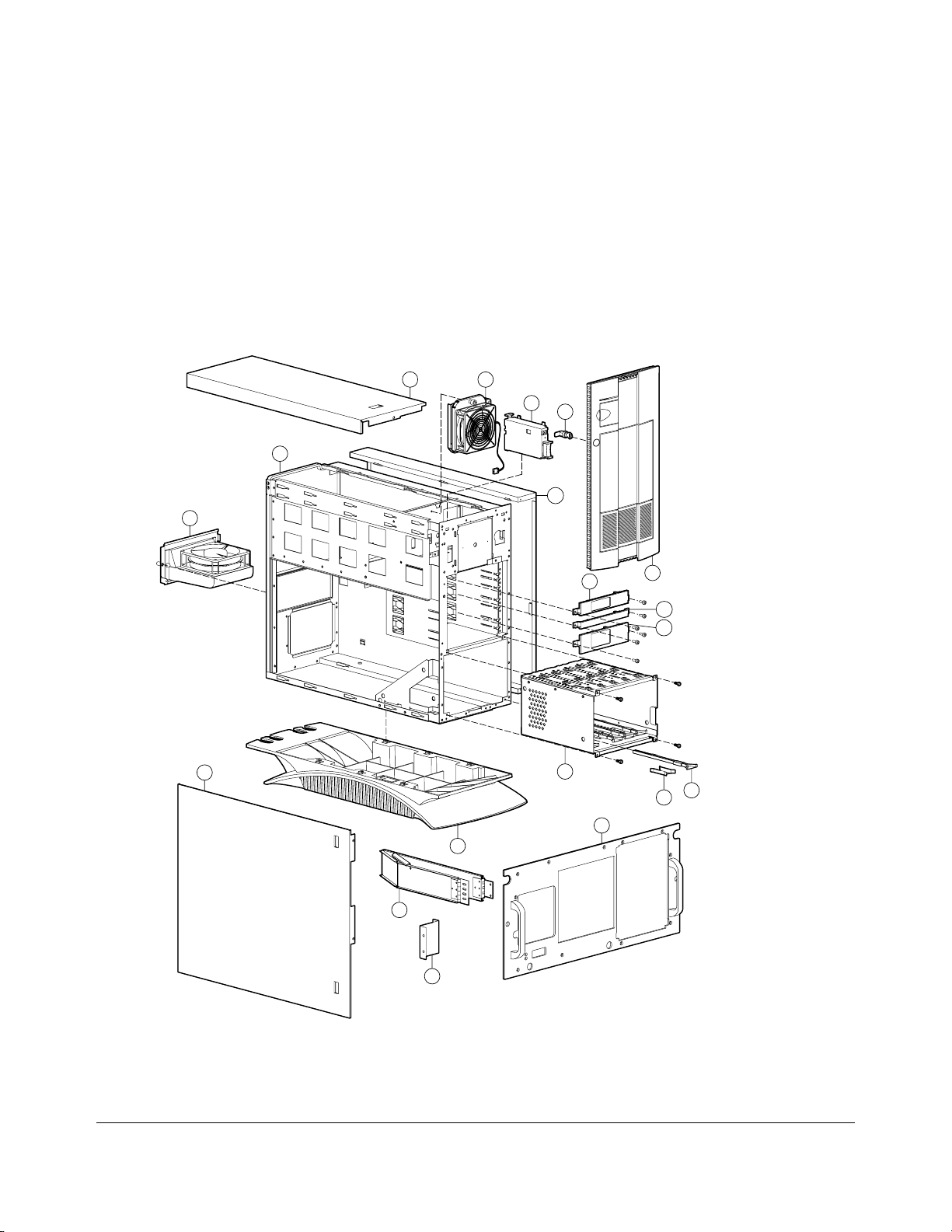
Mechanical Parts Exploded View
3
1
6
2
10
14
19
9
7
16
5
8
4
7
7
12
12
9
9
Figure 1-1.Exploded View of the Compaq ProLiant 2500 and 2500R Server Mechanical
Parts
Compaq ProLiant 2500 Family of Servers Maintenance and Service Guide
Page 9
. . . . . . . . . . . . . . . . . . . . . . . . . . . . . . . . . .
. . . . .
1-2
Illustrated Parts Catalo g
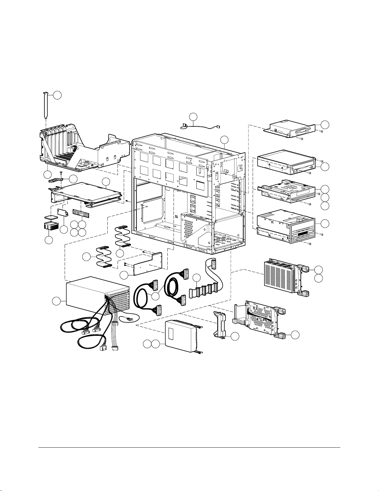
System Components Exploded View
13
52
30
1
33
20
11
24
40
42
43
25
21
22
26
28
27
29
48
53
23
50
47
7
3837
Figure 1-2.Exploded View of the Compaq ProLiant 2500 and 2500R Server System
Components
39
44
Open/Close
Drive
Cassette
Step
Write Protect
DC
35
36
Page 10

. . . . . . . . . . . . . . . . . . . . . . . . . . . . . . . . . .
. . . . .
1-3
Spares Parts List
The Compaq ProLiant 2500 is a tower server. The Compaq ProLiant 2500R is a rackmountable server. Spares that are unique to the tower or rack models are noted in Table 1-
1.
Table 1-1
Spares Parts List - Compaq ProLiant 2500 and 2500R Servers
Item Description Spares Part #
CHASSIS
1 Chassis 271917-001
2 Large Panel (Side panel in Compaq ProLiant 2500, top
panel in 2500R)
3 Small Panel (Top panel in Compaq ProLiant 2500, side
panel in 2500R)
4 Front Bezel Door (Compaq ProLiant 2500 only) 271923-001
5 Front Bezel (Compaq ProLiant 2500R only) 271924-001
6 Processor Fan and Cage 271919-001
7 Bezel Kit (1/6, 1/3, 1/2 Height - Qty 5 each) and Empty Hot-
Pluggable
Drive Cover
8 Base (Compaq ProLiant 2500 only) 271940-001
9 Base Pan/Rack Conversion Kit (Compaq ProLiant 2500R
only)
10 System I/O Fan 281844-001
11 Ejector for Processor Board Tray 271933-001
12 Drive Guide and Ground Spring (Qty 5 each) 146771-001
13 Slot Covers, Clips (Qty 6) 271918-001
14 Power Switch (Push Button) 271929-001
15 Logo Kit (Qty 2) 250907-001 *
ASSEMBLIES
16 Hot-Pluggable Drive Cage w/ Backplane Board (5 x 1-inch
drives)
17 Hot-Pluggable Drive Cage w/ Backplane Board (Duplexed)271932-001
18 Non-Hot-Pluggable Drive Cage (Compaq ProLiant 2500
only)
19 Key-Lock Assembly 148725-001
20 System I/O Board Tray Assembly 271953-001
281846-001
271926-001
189917-001
271927-001
250911-001
271922-001
Continued
Compaq ProLiant 2500 Family of Servers Maintenance and Service Guide
Page 11

. . . . . . . . . . . . . . . . . . . . . . . . . . . . . . . . . .
. . . . .
1-4
Illustrated Parts Catalo g
Spares Parts List - Compaq ProLiant 2500 an d 2500R Se r vers
Item Description Spares Part #
SYSTEM COMPONENTS
21 Power Supply 271916-001
BOARDS
22 Processor Power Module 271935-001
23 System I/O and Processor Backplane Board 250908-001
24 P6/200 MHz Board Tray 271914-001
25 P6/200 MHz Processor Chip with Heatsink 271942-001
MEMORY
26 32-MB DIMM EDO/B (60ns) 281857-001
27 64-MB DIMM EDO/B (60ns) 281858-001
28 128-MB DIMM EDO/B (60ns) 281859-001
29 256-MB DIMM EDO/B (60ns) 281860-001
MASS STORAGE
30 1.44 MB, 3.5-inch Diskette Drive (Standard) 144207-201
31 1.44 MB, 3.5-inch Diskette Drive (Option) 112565-001 *
32 Caddy Load CD-ROM Drive 133881-001 *
33 Tray Load Quad-Speed CD-ROM Drive 184783-001
34 2-GB, 1-inch Fast-Wide SCSI-2 Drive 199878-001 *
35 2.1-GB Pluggable Fast-Wide SCSI-2 Drive 199643-001
36 4.3-GB Pluggable Fast-Wide SCSI-2 Drive 199598-001
37 4.3-GB Non-Pluggable Fast-Wide SCSI-2 Drive 199599-001
38 2.1-GB Non-Pluggable Fast-Wide SCSI-2 199644-001
39 Hot-Pluggable Tray Adapter (Fast-Wide SCSI-2) 199656-001
40 525-MB ACA Tape Drive 142073-201
41 1.2-GB Tape Drive 199615-201 *
42 2/8-GB DAT Drive 142074-201
43 4/16-GB TurboDAT Drive 199464-201
44 4/16-GB TurboDAT Autoloader 199466-201
45 10/20-GB DLT Drive 199746-001 *
46 15/30-GB DLT Drive 242468-001 *
Continued
Continued
Page 12

. . . . . . . . . . . . . . . . . . . . . . . . . . . . . . . . . .
. . . . .
1-5
Spares Parts List - Compaq ProLiant 2500 an d 2500R Se r vers
Item Description Spares Part #
CABLE KITS
47 Wide SCSI Cable (18-inch and 36-inch) 271937-001
48 Diskette Cable 271928-001
49 Diskette/CD-ROM Power Cable 271939-001 *
50 SCSI Cable (non-Hot-Pluggable) 271954-001
51 Power Cable (non-Hot-Pluggable) 250906-001
52 Fan Cable 271920-001
53 IDE/CD-ROM Cable 271936-001
54 Parallel Cable 271938-001 *
Continued
KEYBOARDS
55 Keyboard, U.S. English 160648-101 *
56 Keyboard, U.K. English 160648-103 *
57 Keyboard, German 160648-104 *
58 Keyboard, French 160648-105 *
59 Keyboard, Italian 160648-106 *
60 Keyboard, Spanish 160648-107 *
61 Keyboard, Danish 160648-108 *
62 Keyboard, Norwegian 160648-109 *
63 Keyboard, Swedish/Finnish 160648-110 *
64 Keyboard, Swiss 160648-111 *
65 Keyboard, French Canadian 160648-112 *
66 Keyboard, Portuguese 160648-113 *
67 Keyboard, Turkish 160648-114 *
68 Keyboard, Greek 160648-115 *
69 Keyboard, Latin American 160648-116 *
70 Keyboard, Arabic 160648-117 *
71 Keyboard, Belgian 160648-118 *
72 Keyboard, BHCSY 160648-120 *
73 Keyboard, Hungary 160648-121 *
74 Keyboard, Polish 160648-122 *
75 Keyboard, Slovakia 160648-123 *
76 Keyboard, Russia 160648-124 *
77 Keyboard, Czech 160648-129 *
Continued
Compaq ProLiant 2500 Family of Servers Maintenance and Service Guide
Page 13

. . . . . . . . . . . . . . . . . . . . . . . . . . . . . . . . . .
. . . . .
1-6
Illustrated Parts Catalo g
Spares Parts List - Compaq ProLiant 2500 an d 2500R Se r vers
Item Description Spares Part #
MISCELLANEOUS
78 Miscellaneous Hardware Kit 281847-001 *
79 System ROMpaq 143198-001 *
80 Option ROMpaq 142207-001 *
81 System I/O Battery 160274-001 *
82 Compaq SmartStart CD 183969-001 *
83 Compaq Systems Reference Library CD 183163-001 *
OPTIONS
84 SMART Controller 142130-001 *
85 SMART-2 /E Controller 194752-001 *
86 SMART-2 /P Controller 194754-001 *
87 Fast-SCSI-2/E Controller 142040-001 *
88 32-Bit Fast-Wide SCSI-2/E Controller 199634-001 *
89 32-Bit Fast-Wide SCSI-2/P Controller 199633-001 *
90 NetFlex Controller 142041-001 *
91 NetFlex Controller Token Ring Module 142042-001 *
92 NetFlex-2 Ethernet/Token Ring Controller 142222-001 *
93 NetFlex-2 DualPort Ethernet Controller 142151-001 *
94 NetFlex-2 Token Ring Controller 199521-001 *
95 NetFlex-2 DualPort Token Ring Controller 142195-001 *
96 NetFlex-3/E Controller 169801-001 *
97 NetFlex-3/P Controller 169811-001 *
98 NetFlex-3 100 Base-TX Upgrade Module 169805-001 *
99 NetFlex-3 100 VG-AnyLAN Upgrade Module 169803-001 *
100 10/100 TX PCI UTP Controller 169849-001 *
101 10 T, PCI UTP Controller 242501-001 *
102 4/16 TR PCI IBM UTP/STP Controller 199764-001 *
103 50-Pin to 68-Pin Adapter (Standard to Wide) 189638-001 *
104 68-Pin to 50-Pin Adapter (Wide to Standard) 189631-001 *
105 NIC 10/100 Class B 219414-001 *
* Not Shown
Continued
181132-001 *
Page 14

. . . . . . . . . . . . . . . . . . . . . . . . . . . . . . . . . .
. . . . .
2-1
Chapter 2
Removal and Replacement
Procedures
This chapter provides subassembly/module-level removal and replacement procedures for
the Compaq ProLiant 2500 and Compaq ProLiant 2500R Servers. After completing all
necessary removal and replacement procedures, run the DIAGNOSTICS program to verify
that all components operate properly.
To service Compaq ProLiant 2500 and 2500R Servers, you might need:
■
Torx T-15 screwdriver
■
From the Compaq SmartStart and Support Software CD:
❏
System Configuration Utility software
❏
Drive Array Advanced Diagnostics software
❏
Diagnostics software
The Compaq ProLiant 2500 is a tower server. The Compaq ProLiant 2500R is a
rack-mountable server. The models are identical except for their orientation: on the tower
model, the chassis is upright; on the the rack-mountable model, the chassis is on its side.
Compaq ProLiant 2500 Family of Servers Maintenance and Service Guide
Page 15
. . . . . . . . . . . . . . . . . . . . . . . . . . . . . . . . . .
. . . . .
2-2
Removal and Replacement Procedures
Electrostatic Discharge Information
A discharge of static electricity can damage static-sensitive devices or microcircuitry.
Proper packaging and grounding techniques are necessary precautions to prevent damage.
To prevent electrostatic damage observe the following precautions:
■
Transport products in static-safe containers such as conductive tubes, bags,
or boxes.
■
Keep electrostatic-sensitive parts in their containers until they arrive at static-free
stations.
■
Cover work stations with approved static-dissipating material. Provide a wrist strap
connected to the work surface and properly grounded tools and equipment.
■
Keep work area free of non-conductive materials such as ordinary plastic assembly
aids and foam packing.
■
Always be properly grounded when touching a static-sensitive component
or assembly.
■
Avoid touching pins, leads or circuitry.
■
Always place drives PCB assembly side down on the foam.
■
Use conductive field service tools.
Symbols in Equipme nt
WARNING: Any surface or area of the equipment
marked with these symbols indicates the presence
of a hot surface or ho t co m po nent. I f this s ur f ace is
contacted, the potential for injury ex is ts . T o avo id
risk of injury fro m a ho t co m po nent, allo w the
surface to cool befo r e touching .
WARNING: Any surface or area of the equipment
marked with these symbols indicates the presence
of electrical shock hazards . Enclo s ed ar ea co ntains
no operator serviceable par ts . To avoid risk of injur y
from electrical shock hazar ds, do not open this
enclosure.
WARNING: Any RJ-45 receptacle marked with
these symbols indicates a Netw ork Interface
Connection. To avo id r is k o f electr ical s ho ck, fire, or
damage to the equipment, do not plug telepho ne
or telecommunications co nnecto r s into this
receptacle.
Page 16
. . . . . . . . . . . . . . . . . . . . . . . . . . . . . . . . . .
. . . . .
2-3
Preparation Procedures
Before beginning any of the removal and replacement procedures, complete the following
steps:
1. Turn OFF the server and any peripheral devices.
2. Disconnect the AC power cord from the AC outlet, then from the server.
3. Disconnect all external peripheral devices from the server.
Front Bezel
On the Compaq ProLiant 2500 Server, the front bezel is a door. On the Compaq ProLiant
2500R Server, the front bezel is a plate.
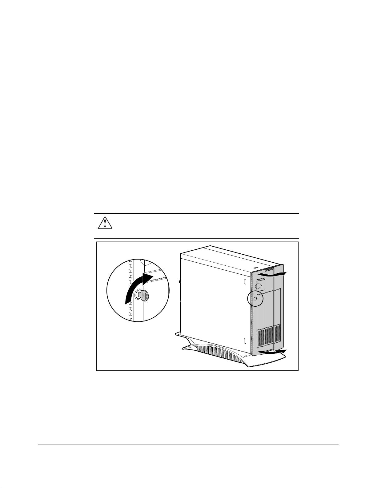
Compaq ProLiant 2500
WARNING: High voltage pres ent. Extreme care m us t be
taken when running the Compaq ProLiant 2500 Server
without the system unit cover on.
MSG005.EPS
Figure 2-1. Opening Front Bezel Door
1. Unlock the front bezel and swing open the door.
Compaq ProLiant 2500 Family of Servers Maintenance and Service Guide
Page 17
. . . . . . . . . . . . . . . . . . . . . . . . . . . . . . . . . .
. . . . .
2-4
Removal and Replacement Procedures
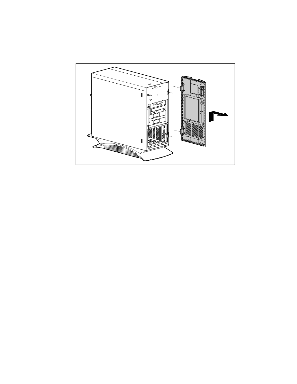
MSG036.EPS
Figure 2-2.Removing the Front Bezel Door
2. Lift and remove the door.
Reverse steps 1 to 2 to replace the front bezel door.
Page 18
. . . . . . . . . . . . . . . . . . . . . . . . . . . . . . . . . .
. . . . .
2-5
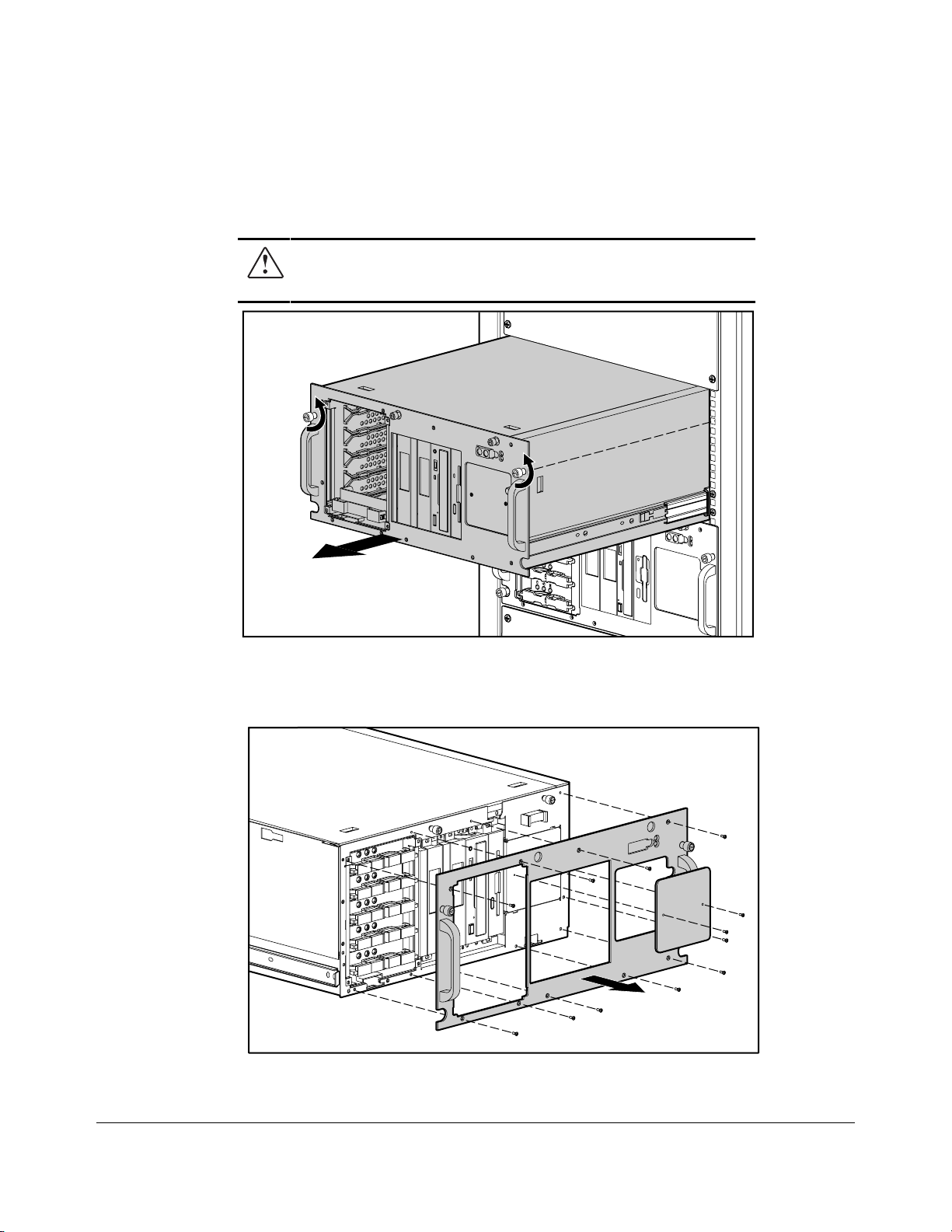
Compaq ProLiant 2500R
WARNING: High voltage pres ent. Extreme care m us t be
taken when running the Compaq ProLiant 2500R Server
without the system unit cover on.
MSG054.EPS
Figure 2-3. Extending the Server from the Rack
1. Unscrew the front panel thumb screws to release the server from the rack.
2. Using the handles, pull the server out from the rack to the locked position.
MSG053.EPS
Figure 2-4. Removing Front Bezel
Compaq ProLiant 2500 Family of Servers Maintenance and Service Guide
Page 19
. . . . . . . . . . . . . . . . . . . . . . . . . . . . . . . . . .
. . . . .
2-6
Removal and Replacement Procedures
3. Remove the screws from the front bezel panel and remove it.
Reverse steps 1 to 3 to replace the front bezel.
Large Access Panel
On the Compaq ProLiant 2500 Server, the large access panel is the side panel. On the
Compaq ProLiant 2500R Server, the large access panel is the top panel.
Compaq ProLiant 2500
MSG006.EPS
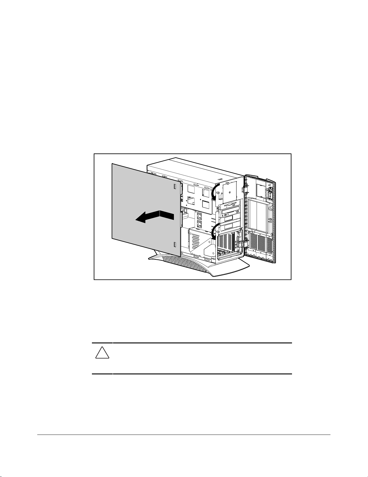
Figure 2-5.Removing the Large Access Panel from the Compaq ProLiant 2500
1. Unlock and open the front bezel door.
2. Loosen the thumb screws on the front panel.
3. Slide the large access panel toward the rear of the unit 0.5 inch (1.5 cm).
4. Lift and remove the large access panel.
CAUTION: Do not operate the server with the large acces s
panel removed. The large acces s panel is an integ r al par t o f
the cooling system and rem oving it while the system is
running may adversely affect data integrity.
Reverse steps 1 to 4 to replace the large access panel.
Page 20
. . . . . . . . . . . . . . . . . . . . . . . . . . . . . . . . . .
. . . . .
2-7
Compaq ProLiant 2500R
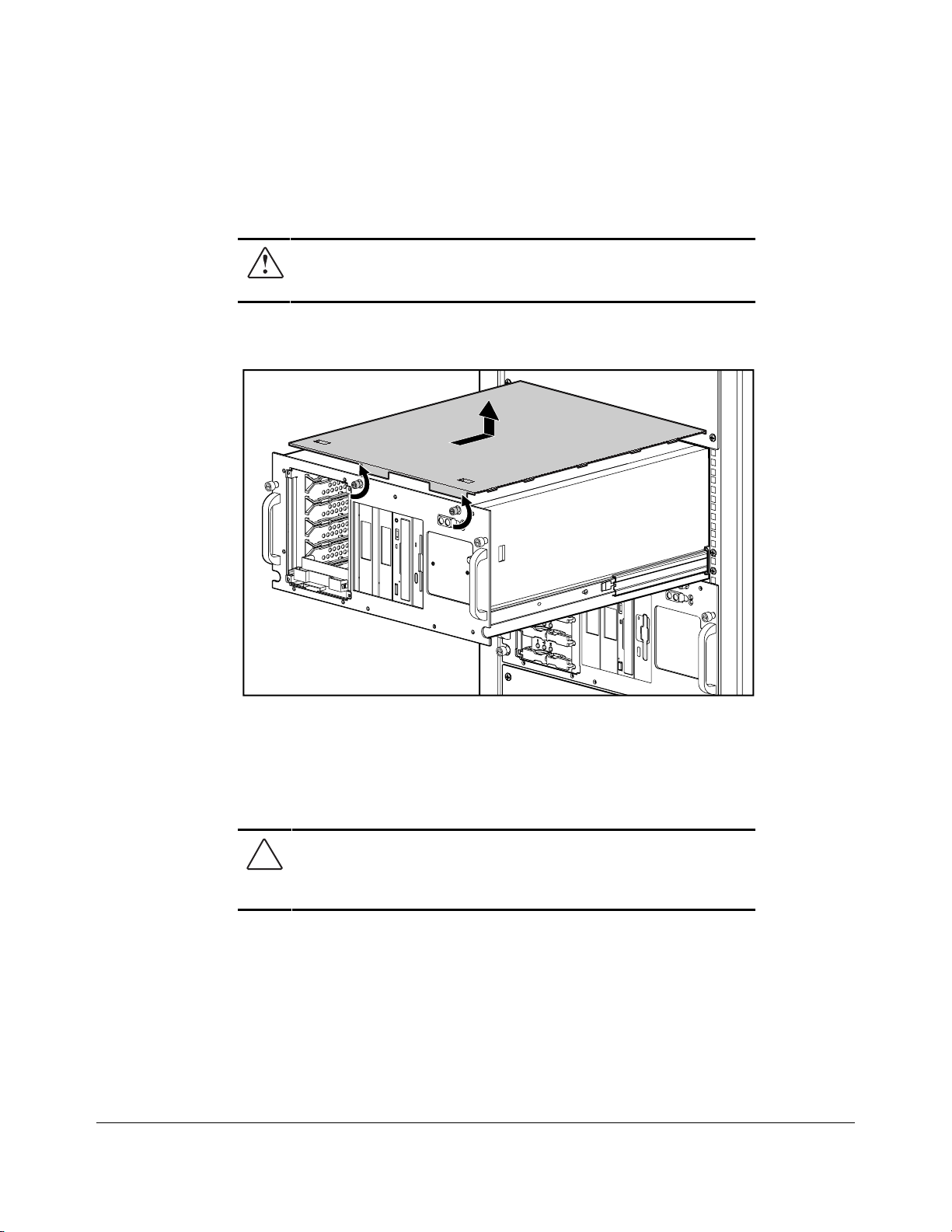
WARNING: High voltage pres ent. Extreme care m us t be
taken when running the Compaq ProLiant 2500R Server
without the system unit cover on.
1. Unscrew the front panel thumb screws to release the server from the rack.
2. Using the handles, pull the server out from the rack to the locked position.
MSG056.EPS
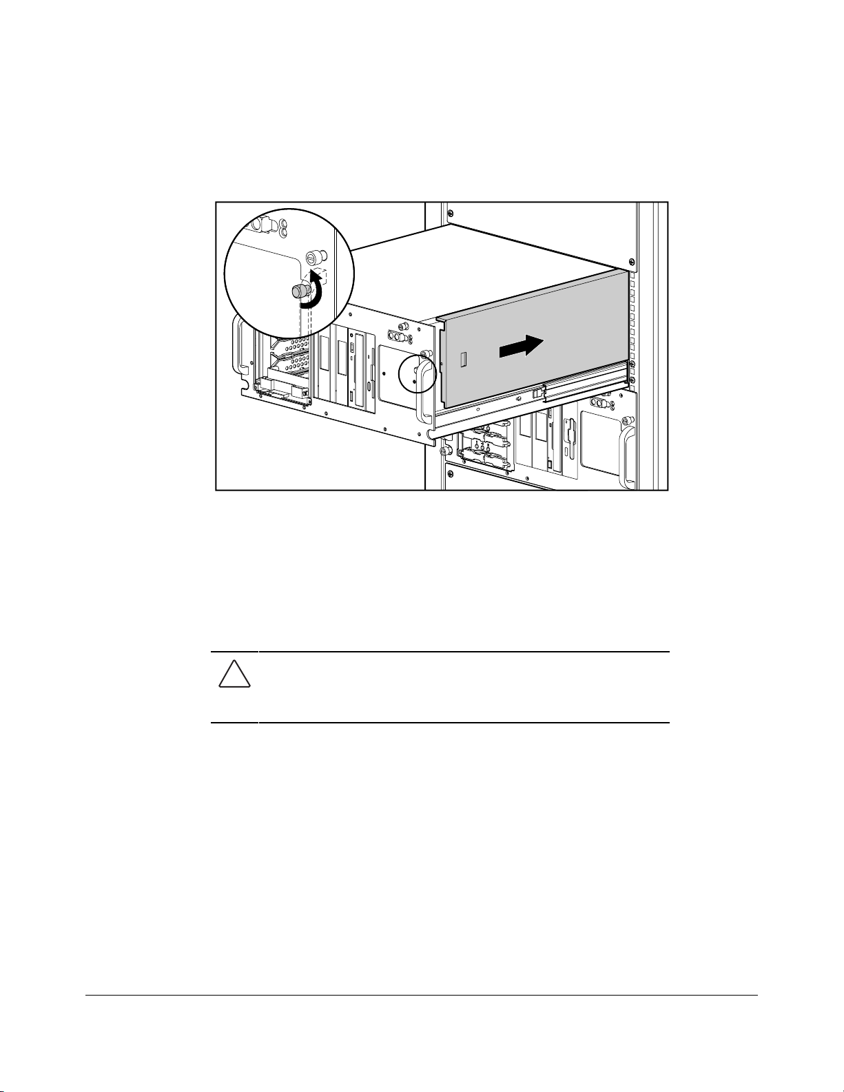
Figure 2-6.Removing the Large Access Panel from the Compaq ProLiant 2500R
3. Turn the two thumbscrews screws on the front bezel.
4. Slide the large access panel toward the rear of the unit 0.5 inch (1.5 cm).
5. Lift and remove the large access panel.
CAUTION: Do not operate the server with the large acces s
panel removed. The large acces s panel is an integ r al par t o f
the cooling system and rem oving it while the system is
running may adversely affect data integrity.
Reverse steps 1 to 5 to replace the large access panel.
Compaq ProLiant 2500 Family of Servers Maintenance and Service Guide
Page 21
. . . . . . . . . . . . . . . . . . . . . . . . . . . . . . . . . .
. . . . .
2-8
Removal and Replacement Procedures
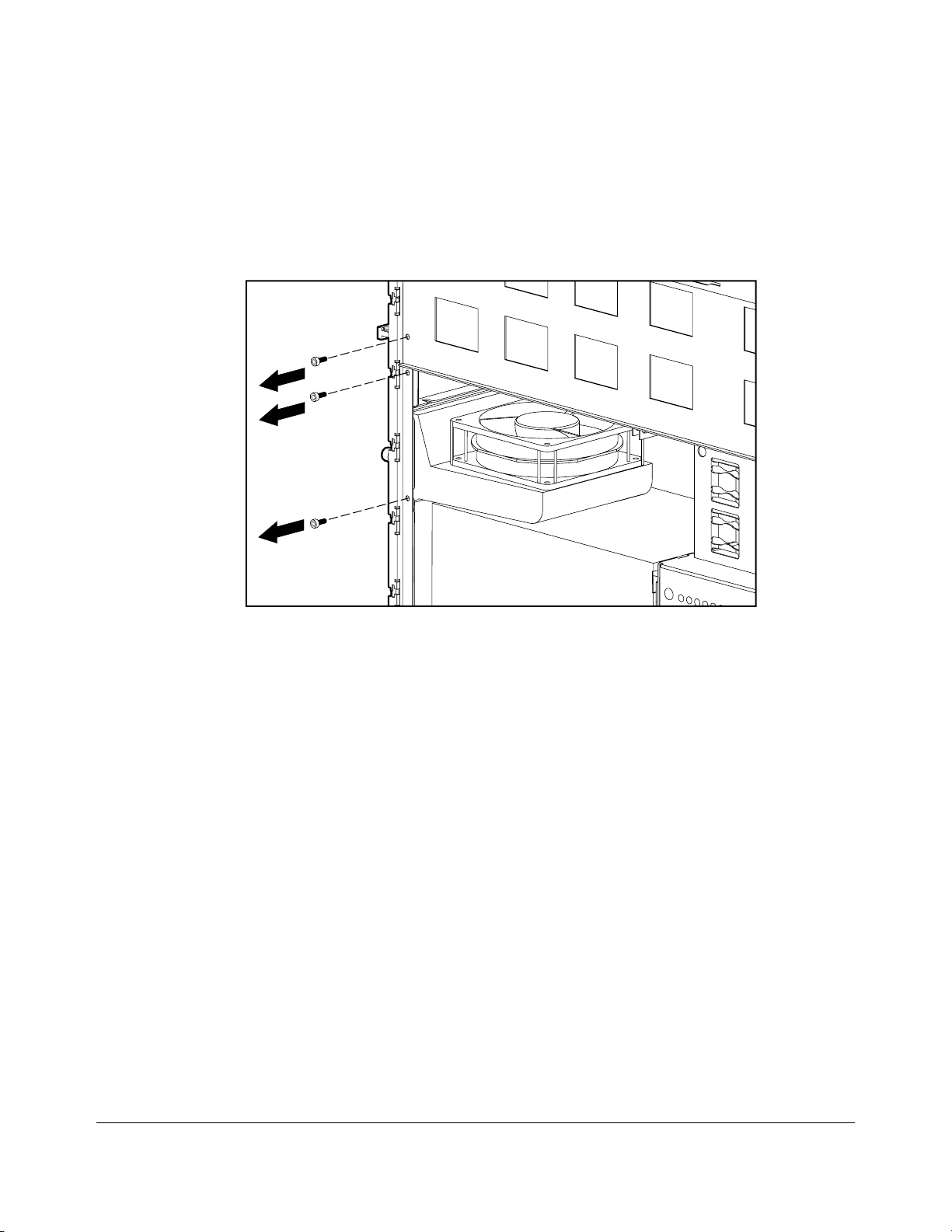
Security Screws
If security screws are in place, you must remove them before you can remove the system
I/O board tray assembly, the processor tray assembly, or the system I/O fan.
MSG039.eps
1
Figure 2-7.Removing Three Se curity Screws
1. If the computer is ON, turn it OFF and disconnect the power cord.
2. Disconnect any other external equipment connected to the computer.
3. Remove the large access panel.
4. Remove the security screws.
Page 22
. . . . . . . . . . . . . . . . . . . . . . . . . . . . . . . . . .
. . . . .
2-9
Small Access Panel
On the Compaq ProLiant 2500, the small access panel is the top panel. On the Compaq
ProLiant 2500R, it is the side panel.
Compaq ProLiant 2500
MSG007.EPS
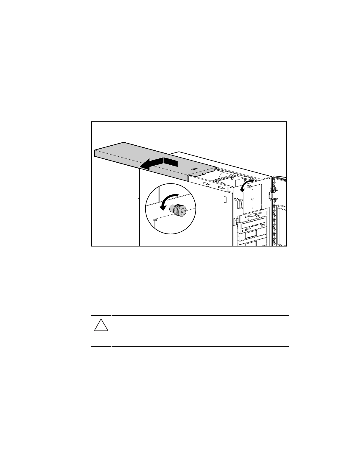
Figure 2-8.Removing the Small Access Panel from the Compaq ProLiant 2500
1. Open the front bezel door.
2. Loosen the side thumb screw on the front panel.
3. Slide the panel toward the rear of the unit about 0.5 inch (1.5 cm) and then slide the
panel to the side of the server.
4. Lift and remove the small access panel.
CAUTION: Do not operate the server with the sm all acces s
panel removed. The sm all acces s panel is an integ r al part o f
the cooling system and rem oving it while the system is
running may adversely affect data integrity.
Reverse steps 1 to 4 to replace the small access panel.
Compaq ProLiant 2500 Family of Servers Maintenance and Service Guide
Page 23
. . . . . . . . . . . . . . . . . . . . . . . . . . . . . . . . . .
. . . . .
2-10
Removal and Replacement Procedures
Compaq ProLiant 2500R
MSG055.EPS
Figure 2-9.Removing the Small Access Panel from the Compaq ProLiant 2500R
1. Pull the server out from the rack to the locked position.
2. Loosen the top thumb screw on the front panel.
3. Slide the panel toward the rear of the unit about 0.5 inch (1.5 cm) and then slide the
panel to the side of the server.
4. Lift and remove the small access panel.
CAUTION: Do not operate the server with the sm all acces s
panel removed. The sm all acces s panel is an integ r al part o f
the cooling system and rem oving it while the system is
running may adversely affect data integrity.
Reverse steps 1 to 4 to replace the small access panel.
Page 24
. . . . . . . . . . . . . . . . . . . . . . . . . . . . . . . . . .
. . . . .
2-11
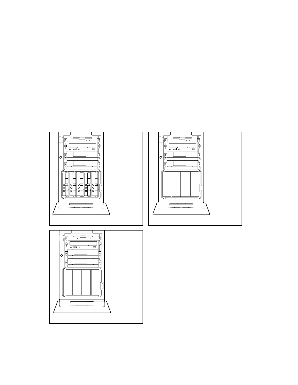
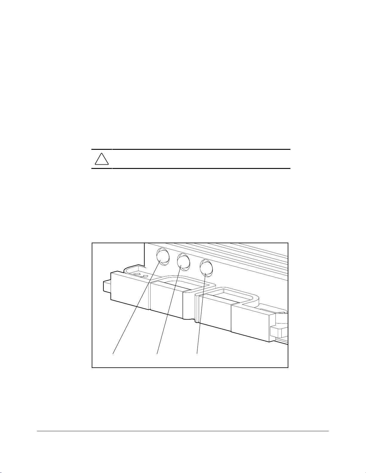
Mass Storage Devices
The Compaq ProLiant 2500 Server contains two areas for mass storage devices: the
removable media area and the hot-pluggable or non-hot-pluggable hard drive cage.
Hot-pluggable models contain a maximum of seven, eight, or nine drive bays depending on
the drive cage option: four in the removable media area, and three, four, or five in the hotpluggable hard drive bays.
Non-hot-pluggable models of the Compaq ProLiant 2500 contain a maximum of eight nonhot-pluggable drive bays: four in the removable media area, and four in the non-hotpluggable hard drive bays.
AA
BB
C
C
D
D
2345
Hot-Pluggable
AA
BB
C
DCD
AA
Removable
Media
Area
BB
C
Removable
Media
Area
DCD
112345
Hot-Pluggable
Hard Drive
Bays
Non-Pluggable
Removable
Media
Area
0101
Duplexed
Hot-Pluggable
Hard Drive
Bays
1234
Non-Hot-Pluggable
Hard Drive
Bays
MSG025.EPS
Duplexed Hot-Pluggable
Figure 2-10. Mass Storage Device Locations and Bay Num b ers
Compaq ProLiant 2500 Family of Servers Maintenance and Service Guide
Page 25
. . . . . . . . . . . . . . . . . . . . . . . . . . . . . . . . . .
. . . . .
2-12
Removal and Replacement Procedures
Removable Media Storage Devices
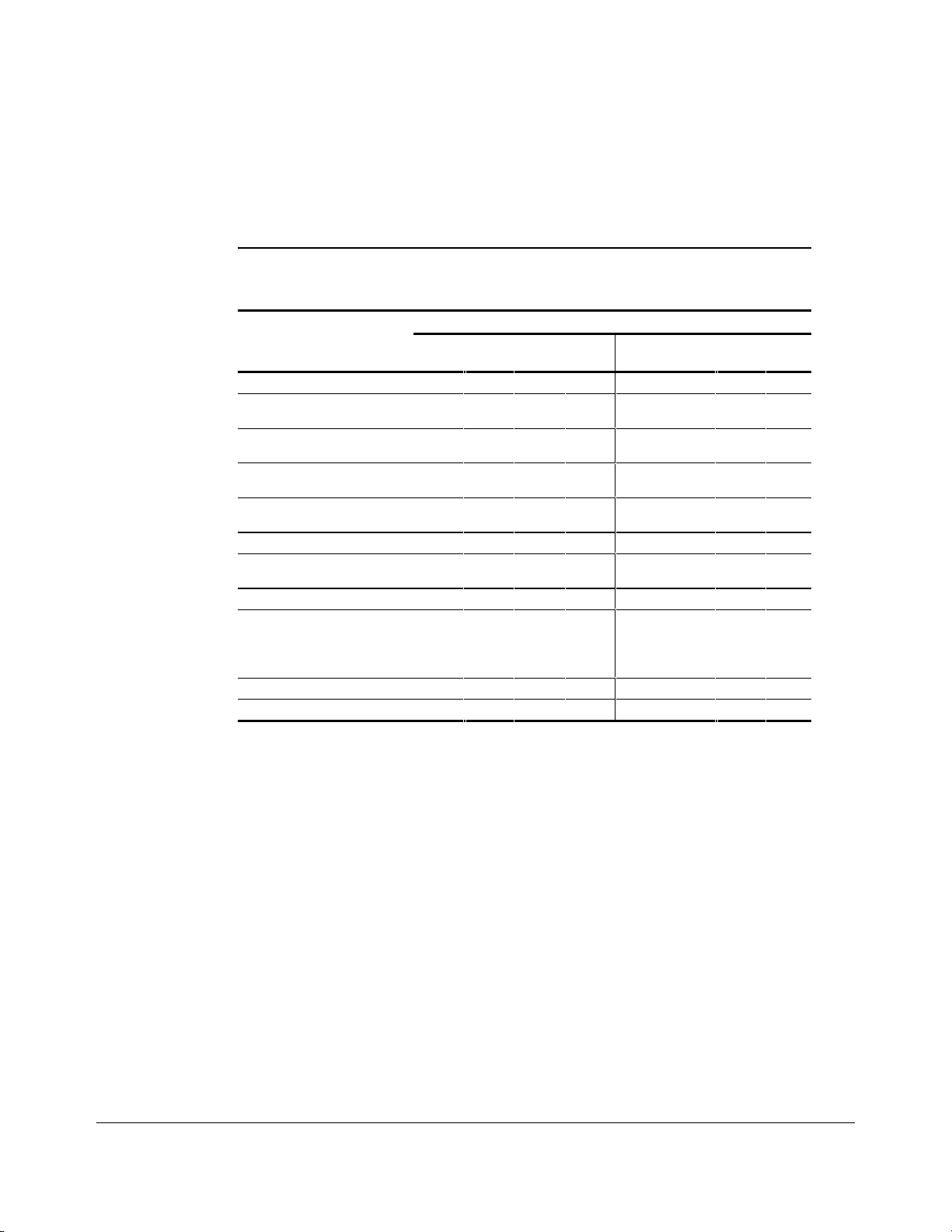
Table 2-1 shows the supported mass storage devices and their supported locations.
Removable Media Bay Configurations
Non-Hot-Pluggable or
Duplexed Models
Mass Storage Device 45675678
1.44-MB, 3.5" Diskette
Drive
1.2-MB, 5.25" Diskette
Drive
2/8-GB DAT (Digital
Audio Tape) Drive
525-MB ACA Tape
Drive
CD-ROM Drive
4/16-GB TurboDAT
Drive
1.2-GB Tape Drive
4/16-GB DAT
Autoloader (Requires
bays 4 and 5
or 5 and 6)
10/20-GB DLT Drive
15/30-GB DLT Drive
✓✓ ✓✓
✓✓ ✓✓
✓✓ ✓✓
✓✓ ✓✓
✓✓ ✓✓
✓✓ ✓✓
✓✓ ✓✓
Table 2-1
✓
Storage Bays
Hot-Pluggable Models
✓✓
✓✓
✓
Page 26
. . . . . . . . . . . . . . . . . . . . . . . . . . . . . . . . . .
. . . . .
2-13
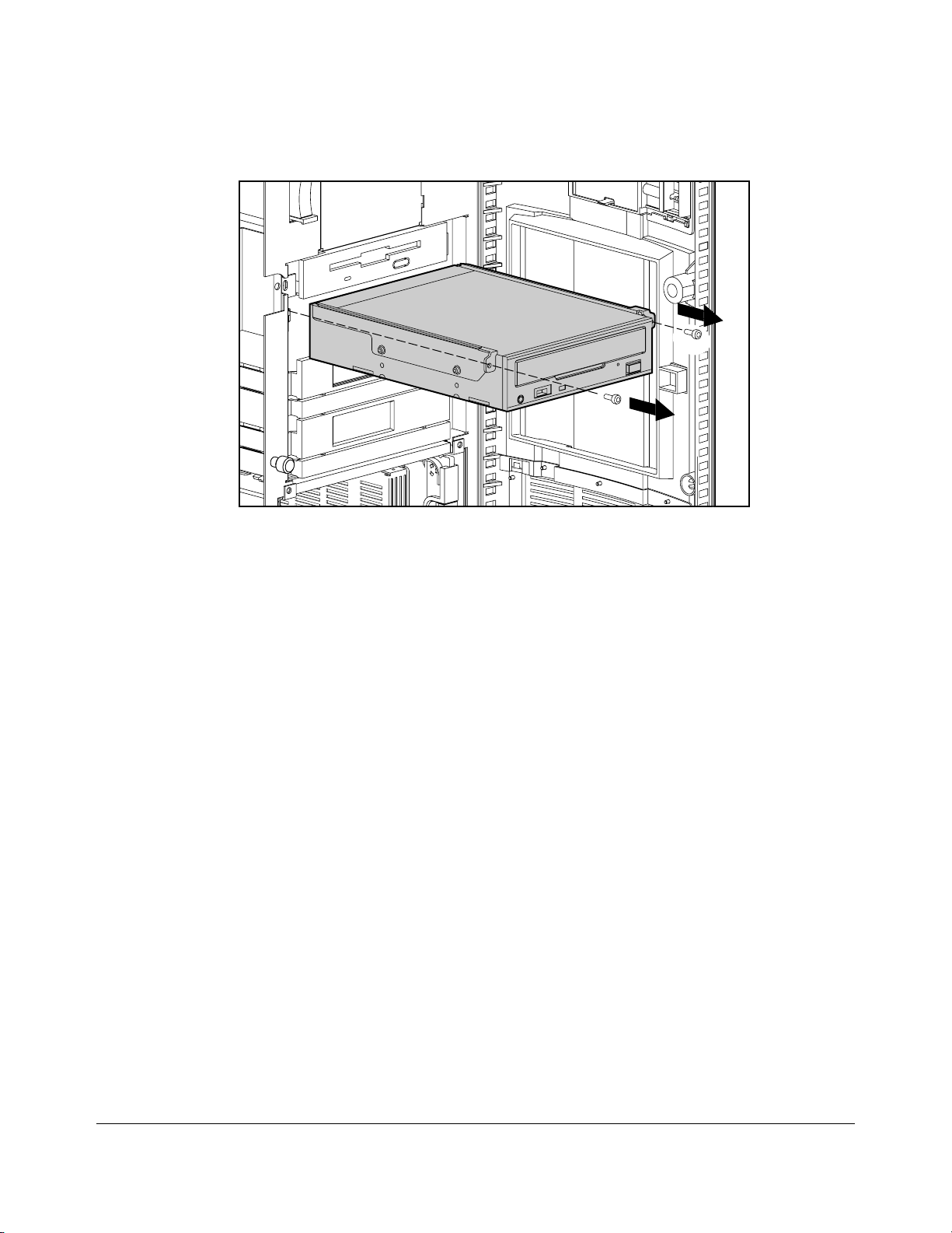
MSG019.EPS
Figure 2-11. Removing a Storage Device from the Removable Media Area
1. Remove the large access panel.
2. Disconnect the power and signal cables from the rear of the storage device.
3. Tower units - open the front bezel door
Rack units - remove the front bezel panel, see page 2-5
4. Remove the retaining screws.
5. Slide the mass storage device out.
Reverse steps 1 to 4 to replace a mass storage device.
Compaq ProLiant 2500 Family of Servers Maintenance and Service Guide
Page 27
. . . . . . . . . . . . . . . . . . . . . . . . . . . . . . . . . .
. . . . .
2-14
Removal and Replacement Procedures
Hot-Pluggable Hard Drives
Hot-pluggable hard drives used in combination with the integrated Wide-Ultra SCSI
Controller can be replaced while the power is on.
NOTE: It is not necessary to set the SCSI ID jumpers on a
Compaq replacement hot- plug g able har d drive. The SCSI
ID is set automatically by the backplane board and the ho tpluggable tray (to a SCSI I D m atching the bay number)
when the drive is installed.
CAUTION: Before removing any hot-pluggable hard drive,
read the guidelines listed in the following section.
Important Guidelines For Replacing
Hot-Pluggable Hard Drives
When you replace a drive configured for fault tolerance, the replacement drive will
automatically begin to be restored. When a drive is being restored, the Online LED will
flash green. The LED will continue to flash until the drive is completely restored.
MSG029.EPS
Online Drive Access Drive Failure
Figure 2-12.Hot-Pluggable Hard Drive LED Indicators
Page 28

. . . . . . . . . . . . . . . . . . . . . . . . . . . . . . . . . .
. . . . .
2-15
When replacing hot-pluggable hard drives, you must follow these guidelines:
■
Never remove more than one drive at a time. When a drive is replaced, the
controller uses data from the other drives in the array to reconstruct data on the
replacement drive. If more than one drive is removed, a complete data set is not
available to reconstruct data on the replacement drive(s).
■
Never remove a working drive when another drive has failed. Drives that have
been failed by the controller are indicated by the amber Drive Failure LED on the
drive tray. Permanent data loss will occur if you remove a working drive when
replacing a failed drive.
■
Never remove a drive while another drive is being rebuilt. A drives’ Online
LED flashes green when it is being rebuilt. A replaced drive is restored from data
stored on the other drives.
■
Never turn a ProLiant Storage System OFF while the server controlling it is
powered ON. Doing so will cause the server’s array controller to mark the drives as
"failed." This could result in permanent data loss.
■
If an online spare drive is installed, wait for it to complete rebuilding before
replacing the failed drive. When a drive fails, the online spare will become active
and begin to be rebuilt as a replacement drive. After the online spare has been
completely rebuilt (Online LED will be on solid), replace the failed drive with a new
drive. Do not replace the failed drive with the online spare.
■
A POST error message (1786) will occur when the system is turned on if a
drive(s) has been replaced while the system is OFF. When this occurs you will
be prompted to:
PRESS F1 TO BOOT THE SYSTEM A ND REBUILD THE REPL ACED DRIVE, OR
PRESS F2 TO BOOT THE SYSTEM A ND NOT REBUILD THE DRIVE(S).
CAUTION: Pressing F2 will cause permanent data loss to the
entire logical drive. Press F2 o nly if all o f the drives have been
replaced or if complete data lo s s is desired.
Compaq ProLiant 2500 Family of Servers Maintenance and Service Guide
Page 29
. . . . . . . . . . . . . . . . . . . . . . . . . . . . . . . . . .
. . . . .
2-16
Removal and Replacement Procedures
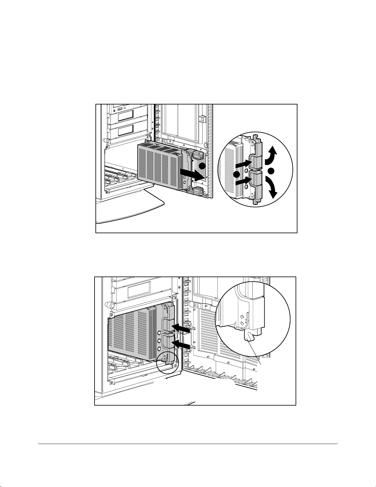
Replacing Hot-Pluggable Hard Drives
The front access drive bay area is behind the front bezel door and can hold up to four or
five third-height hot-pluggable hard drives, depending on the optional drive cage.
C
A
B
MSG030.EPS
Figure 2-13. Removing a Hot- Pluggable Hard Drive
1. Press the releases on the ejector levers [A] and swing levers out [B] as shown.
This will pull the drive out of the backplane connector.
2. Slide the hot-pluggable hard drive out [C].
Be sure ejector levers are in the full
open position to insure a correct latch
MSG-031.EPS
Figure 2-14. Replacing a Hot-Pluggable Hard Drive
while installing.
Ejector lever
must latch
behind the
front panel
of the unit.
Page 30
. . . . . . . . . . . . . . . . . . . . . . . . . . . . . . . . . .
. . . . .
2-17
To Install a Drive
1. Slide the hot-pluggable hard drive all the way into the drive cage.
2. Swing the ejector levers in to seat the drive tray into the backplane connector.
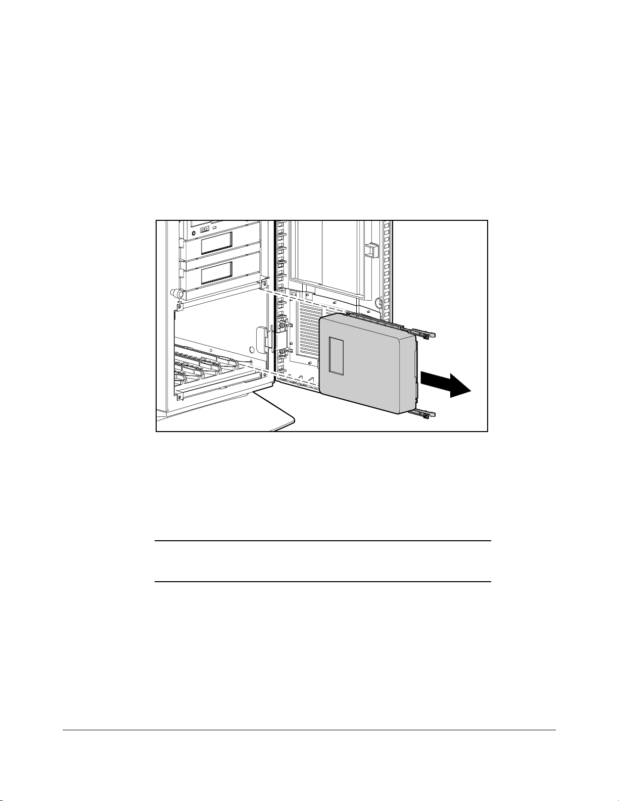
Replacing N on-Hot-Pluggable Hard Drives
MSG018.EPS
Figure 2-15. Removing a Non-Hot-Pluggable Hard Drive
1. Remove the large access panel.
2. Disconnect the power and signal cables from the rear of the hard drive.
3. Squeeze the two release tabs on each side of the drive and slide the drive out.
Reverse steps 1 to 3 to replace a non-hot-pluggable hard drive.
IMPORTANT: Ensure that the SCSI ID s etting o n the r eplaced nonhot-pluggable drive matches the SCSI ID setting on the removed
drive.
Compaq ProLiant 2500 Family of Servers Maintenance and Service Guide
Page 31

. . . . . . . . . . . . . . . . . . . . . . . . . . . . . . . . . .
. . . . .
2-18
Removal and Replacement Procedures
Cable Folding and Routing Diagrams
CAUTION: When routing cables, always make sure that the
cables are not in a position w her e they w ill be pinched o r
crimped.
IMPORTANT: All SCSI hard drives on the same SCSI bus must be
internal (within the server) o r in an ex ter nal s to r ag e s y s tem , but not
both. A configuratio n w ith bo th inter nal and ex ter nal S C S I hard
drives requires more than o ne s ing le-channel SCSI contro ller . A
multi-channel controller, s u ch as the C o m paq S MART - 2 Ar r ay
Controller, s uppo r ts bo th inter nal and ex ter nal S C S I hard dr ives o n
separate SCSI buses.
IMPORTANT: All integrated 32-Bit SCSI- 2 C o ntr o llers must be
terminated by connecting one of the f o llo wing to the Wide-Ultra
SCSI connector o n the s y s tem bo ar d:
■
Terminated SCSI cable
■
SCSI cable that is also attached to a ho t- plug g able
backplane
■
SCSI cable that is also attached to an inter nal SCSI ribbon cable
for non-hot-plug g able SC SI dr ives
Cable Diagram for Diskette Drive
271928-001
Page 32

. . . . . . . . . . . . . . . . . . . . . . . . . . . . . . . . . .
. . . . .
2-19
Figure 2-16. Diskette Drive Cable (Spares Part No. 271928-001)
Compaq ProLiant 2500 Family of Servers Maintenance and Service Guide
Page 33

. . . . . . . . . . . . . . . . . . . . . . . . . . . . . . . . . .
. . . . .
2-20
Removal and Replacement Procedures
Cable Di agram for IDE /CD-ROM
271936-001
COMPACT
Figure 2-17. IDE/CD-ROM Cable (Spares Part No. 271936-001)
Cable Di agram for Hot-P luggable Drive
Cages
271937-001
MSG037.EPS
Figure 2-18. Wide SCSI Cables (Hot-pluggable) (Spares Part No. 271937-001)
Page 34

. . . . . . . . . . . . . . . . . . . . . . . . . . . . . . . . . .
. . . . .
2-21
Cable Di agram for Non-Hot-Pluggable Drive
Cages
271954-001
271937-001
MSG050.EPS
Figure 2-19. SCSI Cable (Non-Hot-Pluggable) (Spares Part No. 271954-001)
Cable Di agram for Duplexed Hot-Pluggable
Hard Drives
271937-001
(36")
To SCSI
Controller Board
271937-001
(18")
MSG049.EPS
Figure 2-20. Cables for Duplexed Hot-Pluggable Hard Drives (Spares Part No.
271937-001)
Compaq ProLiant 2500 Family of Servers Maintenance and Service Guide
Page 35

. . . . . . . . . . . . . . . . . . . . . . . . . . . . . . . . . .
. . . . .
2-22
Removal and Replacement Procedures
Processor Tray Assembly
A
C
B
MSG008.EPS
Figure 2-21. Removing the Processor Tray Assembly
1. If installed, remove the security screw.
2. Lift the catch on the release lever [A] and swing the lever out [B] to unlock the
processor tray assembly.
3. Pull out the tray [C].
Reverse steps 1 to 3 to replace the processor tray assembly.
Page 36

. . . . . . . . . . . . . . . . . . . . . . . . . . . . . . . . . .
. . . . .
2-23
Boards
This section describes how to remove and replace the hot-pluggable hard drive backplane
board, the processor backplane board, memory modules, the system I/O board tray
assembly, processor power module, processor chip, processor board, and expansion boards.
Drive Cage with Hot-Pluggable Dr ive
Backplane Board
MSG035.EPS
Figure 2-22. Removing the Cables from the Hot-Pluggable Drive Backplane Board
1. Remove the large access panel.
2. Disconnect the signal and power cables from the backplane board.
Compaq ProLiant 2500 Family of Servers Maintenance and Service Guide
Page 37

. . . . . . . . . . . . . . . . . . . . . . . . . . . . . . . . . .
. . . . .
2-24
Removal and Replacement Procedures
MSG003EPS
Figure 2-23. Removing the Drive Cage
3. Label and remove all hard drives from the drive cage.
CAUTION: Be sure to label the drives before removing them
so that they can
be replaced in their original positio ns . Failur e to do s o w ill
result in permanent data loss.
4. Remove the four retaining screws from the drive cage.
5. Pull out the drive cage with backplane board.
Reverse steps 1 to 5 to replace the drive cage and backplane board.
Page 38

. . . . . . . . . . . . . . . . . . . . . . . . . . . . . . . . . .
. . . . .
2-25
System I/O and Processor Backplane Board
CD ROM Connector
Floppy Connector
SCSI LED
Connector
Power Supply
Connectors
Power Supply
Connector
Fan
Connectors
SCSI
Connector
MSG038.EPS
Figure 2-24. Removing the System I/O and Processor Backplane Board
1. Remove the large access panel.
2. Remove the processor tray assembly.
3. Remove the system I/O board tray assembly (refer to “System I/O Board Tray
Assembly” later in this document).
4. Disconnect the signal and power cables for the processor backplane board.
MSG034.EPS
Figure 2-25. Removing the System I/O and Processor Backplane Board
Compaq ProLiant 2500 Family of Servers Maintenance and Service Guide
Page 39

. . . . . . . . . . . . . . . . . . . . . . . . . . . . . . . . . .
. . . . .
2-26
Removal and Replacement Procedures
5. Remove the retaining screws.
6. Slide the processor backplane board over, and lift it off.
Reverse steps 1 to 6 to replace the system I/O and processor backplane board.
Memory
The Compaq ProLiant 2500 and 2500R Servers come standard with 32 megabytes of
memory. Memory can be expanded to a maximum of 1.024 gigabytes by installing 60-ns
or faster EDO- or FASTPAGE-buffered, 32-, 64-, 128-, or 256-MB, 4-K refreshed Dual
Inline Memory Modules (DIMMs) on the Pentium Pro processor board.
A
A
B
MSG011.EPS
Figure 2-26. Removing the DIMM Module
1. If installed, remove the security screw for the processor tray assembly.
2. Slide out the processor tray assembly from the rear of the unit.
3. Turn the assembly over.
4. Press both DIMM connector latches outward [A].
5. Lift the DIMM module out [B]
Reverse steps 1 to 5 to replace the DIMM module.
IMPORTANT: A memory module can be ins t alled o ne w ay only. Be
sure to match the two
memory socket. Push the module down into the socket, ensuring
that the module is fully inserted and pr o per ly s eated.
key slots
on the module with the tab on the
Page 40

. . . . . . . . . . . . . . . . . . . . . . . . . . . . . . . . . .
CAUTION:
NOTE:
JEDEC-compliant DI MMs that co nform to this parity schem e.
. . . . .
2-27
The following guidelines MUST be followed when installing or replacing memory:
■
Use only 32-, 64-, 128-, or 256-megabyte; EDO- or FASTPAGE-buffered; 4-K
refreshed DIMMs.
■
DIMMs must be 60-ns or faster.
Use only Fast-Page/EDO Mode 72-Bit Wide JEDEC
standard DIMMs
using 3.3 volts and ECC capability. U s e ED O - buf f ered D I MMs .
Non-compatible DIMMs may adversely affect data integrity.
The specific DIMM bit pattern required to support error
checking and correcting (EC C ) m em o r y is bas ed on the
parity scheme; one byte data, one bit parity. The data byte
and parity are constructed of D RAMs that ar e "n" lo catio ns
deep by 4-bits wide or 1-bit wide and "n" can be any
number. (That is, "n" locations deep x 4-bits wide or "n"
locations deep x 1-bit wide. ) U s e o nly Compaq DIMMs o r
The following table shows typical memory configurations for Compaq ProLiant 2500 and
2500R Servers with the Pentium Pro processor.
Table 2-2
Examples of DIMM Upgrade Combinations
Total Memory Slot 1 Slot 2 Slot 3 Slot 4
32 MB 32 MB
64 MB 32 MB 32 MB
64 MB 64 MB
96 MB 64 MB 32 MB
96 MB 32 MB 32 MB 32 MB
256 MB 128 MB 128 MB
256 MB 64 MB 64 MB 64 MB 64 MB
512 MB 128 MB 128 MB 128 MB 128 MB
512 MB 256 MB 256 MB
768 MB 256 MB 256 MB 128 MB 128 MB
1.024 GB 256 MB 256 MB 256 MB 256 MB
Compaq ProLiant 2500 Family of Servers Maintenance and Service Guide
Page 41

. . . . . . . . . . . . . . . . . . . . . . . . . . . . . . . . . .
. . . . .
2-28
Removal and Replacement Procedures
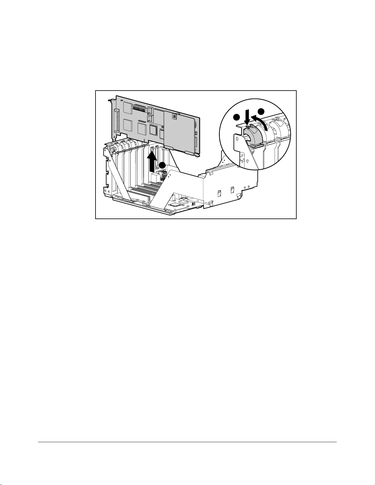
System I/O Board Tray Assembly
A
C
B
MSG009.EPS
Figure 2-27. Removing the System I/O Board Tray Assembly
1. Remove the small access panel.
2. If installed, remove the security screw.
3. Disconnect all cables from expansion boards.
4. Press down the catch on the release lever [A] and swing the lever out [B] to unlock
the system I/O board tray assembly.
5. Pull out the tray [C].
6. Remove all expansion boards from the assembly.
Reverse steps 1 to 6 to replace the system I/O board tray assembly.
Page 42

. . . . . . . . . . . . . . . . . . . . . . . . . . . . . . . . . .
. . . . .
2-29
Parallel Connector Interface
Auxiliary Battery Connector
LCD Module Option
Connector
Auxiliary Speaker
Connector
Integrated/Auxiliary
Battery Connector
MSG023.EPS
Figure 2-28. System I/O Board Connectors
Processor Power Module
The processor power modules are located on the processor board.
MSG040.EPS
Figure 2-29. Removing the Processor Power Module
1. If installed, remove the security screw for the processor tray assembly.
2. Slide out the processor tray assembly from the rear of the unit.
Compaq ProLiant 2500 Family of Servers Maintenance and Service Guide
Page 43

. . . . . . . . . . . . . . . . . . . . . . . . . . . . . . . . . .
. . . . .
2-30
Removal and Replacement Procedures
3. Turn over the tray assembly.
4. Lift out the module.
Reverse steps 1 to 4 to replace the processor power module.
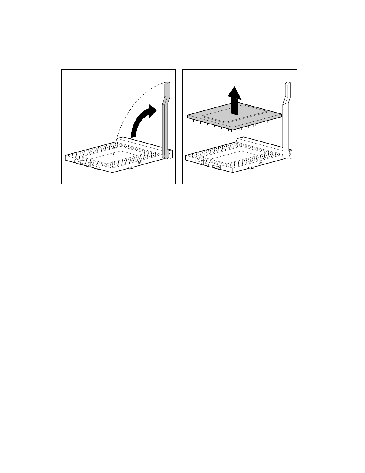
Processor Chip
MSG051.EPS
A
B
C
Figure 2-30. Removing the Heat Sink
1. If installed, remove the security screw for the processor tray assembly.
2. Slide out the processor tray assembly from the rear of the unit.
3. Turn over the tray assembly.
4. Press down and lift up [A] on the heat sink retaining clip. Pull it up [B] and off [C].
5. Remove the heat sink and thermal pad.
Page 44
. . . . . . . . . . . . . . . . . . . . . . . . . . . . . . . . . .
. . . . .
2-31
MSG052a.EPS
Figure 2-31. Removing a Processor Chip
Compaq ProLiant 2500 Family of Servers Maintenance and Service Guide
Page 45

. . . . . . . . . . . . . . . . . . . . . . . . . . . . . . . . . .
. . . . .
2-32
Removal and Replacement Procedures
6. Unlatch the lever and lift.
7. Remove processor chip.
Reverse steps 1 to 7 to replace the processor chip.
CAUTION: Align the pin pattern on the processor to that of
the processor socket.
Processor Board
The processor board can be replaced only by replacing the processor tray assembly.
1. If installed, remove the security screw for the processor tray assembly.
2. Slide out the processor tray assembly from the rear of the unit.
3. Remove memory modules and install them on the new processor tray assembly.
4. Remove the processor power module and install it on the new processor tray
assembly.
5. Remove the processor chip and install it on the new processor tray assembly.
6. Slide in the new processor tray assembly.
Page 46
. . . . . . . . . . . . . . . . . . . . . . . . . . . . . . . . . .
. . . . .
2-33
Expansion Boards
A
C
B
MSG016.EPS
Figure 2-32. Removing the Expansion Board
1. Remove the small access panel.
2. Press on the top of the expansion slot latch [A] and open the latch toward the rear of
the expansion slot cage [B].
3. Pull out expansion board [C].
Reverse steps 1 to 3 to replace the expansion board.
Compaq ProLiant 2500 Family of Servers Maintenance and Service Guide
Page 47

. . . . . . . . . . . . . . . . . . . . . . . . . . . . . . . . . .
. . . . .
2-34
Removal and Replacement Procedures
Power Supply
MSG024.EPS
C
Figure 2-33.Removing the Power Switch
1. Remove the large access panel.
2. Disconnect all power connectors from boards and/or peripheral devices.
3. Remove the retaining screw from the power switch bracket [A].
4. Press the release tab on the power switch bracket [B] and slide the bracket back [C]
and up [D].
B
D
A
5. Remove power switch and cable from bracket (refer to Figure 2-35).
MSG004.EPS
Page 48

. . . . . . . . . . . . . . . . . . . . . . . . . . . . . . . . . .
. . . . .
2-35
Figure 2-34.Removing the Power Supply
6. Remove the four screws at the rear of power supply.
7. Lift power supply out, pulling switch and cable through chassis.
Reverse steps 1 to 7 to replace the power supply.
IMPORTANT: When replacing the power supply, make sure
that the power switch cable is proper ly thr eaded thro ug h the
bracket’s strain relief as s ho w n in Fig ur e 2-35.
Figure 2-35. Power Supply Switch Cable Strain Relief Bracket
Compaq ProLiant 2500 Family of Servers Maintenance and Service Guide
Page 49

. . . . . . . . . . . . . . . . . . . . . . . . . . . . . . . . . .
. . . . .
2-36
Removal and Replacement Procedures
Miscellaneous Parts
System I/O Fan
MSG047.EPS
Figure 2-36. Removing the System I/O Fan
1. Remove the small access panel.
2. Turn the thumbscrew [A] to loosen the system I/O fan.
3. Tilt the system I/O fan [B] and pull it out.
A
B
C
4. Disconnect the fan cable [C].
Reverse steps 1 to 4 to replace the system I/O fan.
Page 50

. . . . . . . . . . . . . . . . . . . . . . . . . . . . . . . . . .
. . . . .
2-37
Processor Fan
MSG015.EPS
B
Figure 2-37. Opening the Processor Fan Door
1. Turn the thumb screw on the processor fan door [A].
2. Open the processor fan door and pull out the processor fan [B].
A
MSG015A.EPS
Figure 2-38. Removing the Processor Fan
3. Disconnect the fan cable.
Reverse steps 1 to 3 to replace the processor fan.
Compaq ProLiant 2500 Family of Servers Maintenance and Service Guide
Page 51

. . . . . . . . . . . . . . . . . . . . . . . . . . . . . . . . . .
. . . . .
2-38
Removal and Replacement Procedures
Page 52

. . . . . . . . . . . . . . . . . . . . . . . . . . . . . . . . . .
. . . . .
2-39
Battery
MSG042.EPS
Figure 2-39. Battery Module
1. Remove the small access panel.
2. Remove expansion boards if necessary.
3. Connect the battery cable to the b attery header on the system I/O board.
4. Move the jumper on connector E2 from pins 1 and 2 to pins 2 and 3.
5. Attach the battery to the tray assembly using the self-stick adhesive.
6. Run Compaq System Configuration Utility.
CAUTION: Do not remove the lithium battery from the
system I/O board. Permanent damage may occur to the
system I/O boar d if r em o ved. If the battery fails, us e the
battery module replacement.
WARNING: The battery/clock module contains a lithium
battery that may explode if mishandled. Do not abuse,
recharge, disassem ble, o r dis po s e o f in fire or heat above 90°
C, incinerate, or expose to water or fire. Use only
replacement battery/clock modules s u pplied by C o m p aq
Computer Corporation.
Compaq ProLiant 2500 Family of Servers Maintenance and Service Guide
Page 53

. . . . . . . . . . . . . . . . . . . . . . . . . . . . . . . . . .
. . . . .
3-1
Chapter 3
Diagnostic Tools
This chapter describes software and firmware diagnostic tools available for the Compaq
Server products. These include:
■
Power-On Self-Test (POST)
■
Diagnostics (DIAGS)
■
Drive Array Advanced Diagnostics (DAAD)
■
Automatic Server Recovery
■
ROMPaq utilities to upgrade flash ROMs
Utility Access
The Compaq SmartStart and Support Software CD contains the SmartStart program and
many of the Compaq utilities needed to maintain your system, including:
■
System Configuration Utility
■
Array Configuration Utility
■
Drive Array Advanced Diagnostics Utility
■
ROMPaq Firmware Upgrade Utilities
CAUTION: Do not select the Erase Utility when running the
SmartStart and Support So ftware CD. This w ill r esult in data
loss to the entire system.
There are several ways to access these utilities:
■
Run the Utilities on the System Partition.
If the system was installed using the SmartStart utility, the Compaq utilities will
automatically be available on the system partition. The system partition could also
have been created during a manual system installation.
To run the utilities on the system partition, boot the system and press F10 when the
cursor moves to the upper right corner of the screen. (If the cursor does not move
to the upper right corner of the screen, the system partition does not exist.) Then
select the utilities from the menu.
❏
The System Configuration Utility is available under System Configuration
menu.
❏
The Array Configuration Utility is available under the System Configuration
menu.
Compaq ProLiant 2500 Family of Servers Maintenance and Service Guide
Page 54

. . . . . . . . . . . . . . . . . . . . . . . . . . . . . . . . . .
. . . . .
3-2
Diagnostic Too ls
❏
The Drive Array Advanced Diagnostics Utility is available under the
Diagnostics and Utilities menu.
❏
The ROMPaq Firmware Upgrade Utility is available under the Diagnostics and
Utilities menu.
■
Run the Utilities from diskette.
You can also run the utilities from their individual diskettes. If you have a utility
diskette newer than the version on the SmartStart and Support Software CD, use that
diskette.
You can also create a diskette version of the utility from the SmartStart and Support
Software CD. To create diskette versions of the utilities from the CD:
1. Boot the computer from the Compaq SmartStart and Support Software CD.
2. From the Compaq System Utilities screen, select Create Support Software and
press the Next button.
3. Select the diskette you would like to create from the list and follow the
instructions on the screen.
■
Run the Utilities from the Compaq SmartStart and Support Software CD.
You can run some utilities directly from the Compaq SmartStart and Support
Software CD. To run these utilities:
1. Boot the Compaq SmartStart and Support Software CD.
2. From the Compaq System Utilities screen, select the utility you wish to run and
press the Next button.
❏
To execute the System Configuration Utility, select Run System
Configuration Utility.
❏
To execute the Array Configuration Utility, select Run Array
Configuration Utility.
IMPORTANT: Only the System Co nf ig ur atio n U t ility and the Arr ay
Configuration Utility can be ex ecuted f r o m the C o m paq S m ar tStar t
and Support Softw ar e C D . All other utilities can be executed only
from the system partition or from diskette.
Page 55

. . . . . . . . . . . . . . . . . . . . . . . . . . . . . . . . . .
. . . . .
3-3
Power-On Self-Test (POST)
POST is a series of diagnostic tests that run automatically on Compaq computers when the
system is turned on. POST checks the following assemblies to ensure that the computer
system is functioning properly:
■
Keyboard
■
Power supply
■
System board
■
Memory
■
Memory expansion boards
■
Controllers
■
Diskette drives
■
Hard drives
If POST finds an error in the system, an error condition is indicated by an audible and/or
visual message. If an error code is displayed on the screen during POST or after resetting
the system, follow the instructions in Table 3-1. The error messages and codes listed in
Table 3-1 include all codes generated by Compaq products.
Your system will generate only those codes that are applicable to your configuration and
options.
Table 3-1
POST Error Messages
Error Code Beeps Probable Source of
Problem
A Critical Error
occurred prior to
this power-up
101-ROM Error 1L,1S System ROM
101-I/O ROM Error None Options ROM
None A catastrophic system
error, which caused
the server to crash, has
been logged.
checksum.
checksum.
Action
Run Diagnostics.
Replace failed
assembly as indicated.
Run Diagnostics.
Replace failed
assembly as indicated
or contact your service
provider.
Run Diagnostics.
Replace failed
assembly as indicated
or contact your service
provider.
Compaq ProLiant 2500 Family of Servers Maintenance and Service Guide
Page 56

. . . . . . . . . . . . . . . . . . . . . . . . . . . . . . . . . .
. . . . .
3-4
Diagnostic Too ls
102-System Board
Failure
104-ASR Timer
Failure
162-System Options
Not Set
None DMA, timers, etc. Replace the system
board. Run the
Compaq System
Configuration Utility.
None System board failure. Run Diagnostics.
2S Configuration
incorrect.
Run the System
Configuration Utility
and correct.
Continued
Page 57

. . . . . . . . . . . . . . . . . . . . . . . . . . . . . . . . . .
. . . . .
3-5
POST Error Messages
Error Code Beeps Probable Source of
163-Time & Date
Not Set
164-Memory Size
Error
170- Expansion
Device Not
Responding
172- Configuration
Nonvolatile
Memory Invalid
172-1
Configuration
Nonvolatile
Memory Invalid
172-2 IRC
Configuration
Invalid
173- Slot ID
Mismatch
174Configuration/Slot
Mismatch Device
Not Found
175Configuration/Slot
Mismatch Device
Found
176-Slot with Not
Readable ID Yields
Valid ID
177-Configuration
Not Complete
Continued
2S Invalid time or date in
2S Configuration memory
None EISA or PCI Expansion
None Nonvolatile
None Nonvolatile
None IRC configuration not
None Board replaced, but
None EISA or PCI board not
None EISA or PCI board
None EISA or PCI board in slot
None Incomplete System
Problem
configuration memory.
incorrect.
board failure.
configuration corrupt
or jumper installed.
configuration corrupt.
set up properly.
- COM Port invalid
- PCI COM Port
- Incorrect IRQ
configuration not
updated.
found.
added, configuration
not updated.
that should contain an
ISA board.
Configuration.
Action
Run the System
Configuration Utility
and correct.
Run the System
Configuration Utility
and correct.
Check board for
secure installation.
Replace the failed
board if necessary.
Run the System
Configuration Utility
and correct.
Run the System
Configuration Utility
and correct.
Run the System
Configuration Utility
and correct.
Run the System
Configuration Utility
and correct.
Run the System
Configuration Utility
and correct.
Run the System
Configuration Utility
and correct.
Run the System
Configuration Utility
and correct.
Run the System
Configuration Utility
and correct.
Compaq ProLiant 2500 Family of Servers Maintenance and Service Guide
Page 58

. . . . . . . . . . . . . . . . . . . . . . . . . . . . . . . . . .
. . . . .
3-6
Diagnostic Too ls
178-Processor
Configuration
Invalid
179-System
Revision Mismatch
201-Memory Error None RAM failure. Run Diagnostics.
203-Memory
Address Error
None Processor type or step
does not match
configuration memory.
None A board was installed
that has a different
revision date.
None RAM failure. Run Diagnostics.
Run the System
Configuration Utility
and correct.
Run the System
Configuration Utility
and correct.
Continued
Page 59

. . . . . . . . . . . . . . . . . . . . . . . . . . . . . . . . . .
. . . . .
3-7
POST Error Messages
Error Code Beeps Probable Source of
205-Cache
Memory Error
Option-Cache
Memory Error
206-Cache
Controller Error
207-Invalid
Memory
Configuration Check SIMM
Installation
208-Invalid
Memory Speed Check SIMM
Installation
211-Cache Switch
Set Incorr ectly
212-System
Processor
Failed/Mapped
out
213-Cache size
Error
(ProSignia VS only)
213-System
Processor Not
Installed
301-Keyboard Error None Keyboard failure. Turn off the computer,
Continued
None Cache memory error.
None Cache controller
None Memory module
1L, 1S The speed of the
None Switch not set properly
1S Processor in slot x
None Invalid optional cache
1S System processor
Problem
Option Cache Memory
Error.
failure.
installed incorrectly.
memory is too slow,
where: xx00 =
expansion board
SIMMs are too slow, or
00yy = syste m board
SIMMs are too slow.
xx and yy have same
bit set.
during installation or
upgrade.
failed.
size.
configured for slot
indicated is missing.
Action
Replace the processor
board in the slot
indicated.
Replace the option
cache board.
Run Diagnostics.
Verify placement of
memory modules.
The speed of the
memory modules must
be 60 or 70 ns. Verify
the speed of the
memory modules
installed and replace.
Verify switch sett ings.
Run Diagnostics and
replace failed
processor.
Replace cache with
256K cache.
Install processor in the
slot indicated or run
the System
Configuration Utility to
remove the processor
from the
.
CFG
file.
then reconnect the
keyboard.
Compaq ProLiant 2500 Family of Servers Maintenance and Service Guide
Page 60

. . . . . . . . . . . . . . . . . . . . . . . . . . . . . . . . . .
. . . . .
3-8
Diagnostic Too ls
301-Keyboard Error
or Test Fixture
Installed
ZZ
-301-Keyboard
Error
303-Keyboard
Controller Error
None Keyboard failure. Replace the ke yboard.
None Keyboard failure. (
represents the
Keyboard Scan Code.)
None System board,
keyboard, or mouse
controller failure.
ZZ
1. A key is stuck. Try to
free it.
2. Replace the
keyboard.
Check with your
Authorized Compaq
Reseller.
Continued
Page 61

. . . . . . . . . . . . . . . . . . . . . . . . . . . . . . . . . .
. . . . .
3-9
POST Error Messages
Error Code Beeps Probable Source of
304-Keyboard or
System Unit Error
40X-Parallel Port X
Address
Assignment
Conflict
402-Monochrome
Adapter Failure
501-Display
Adapter Failure
601-Diskette
Controller Error
605-Diskette Drive
Type Error
702-A coprocessor
has been
detected that was
not reported by
CMOS.
703-CMOS reports
a coprocessor that
has not been
detected
Continued
None Keyboard, keyboard
2S Both external and
1L,2S Monochrome display
1L,2S Video display
None Diskette controller
2S Mismatch in drive type. Run the System
None Installed coprocessor
2S Coprocessor or
Problem
cable, or system board
failure.
internal ports are
assigned to parallel
port X.
controller.
controller.
circuitry failure.
not configured.
configuration error.
Action
1. Make sure the
keyboard is
attached.
2. Run Diagnostics to
determine which is
in error.
3. Replace the part
indicated.
Run the System
Configuration Utility.
Replace the
monochrome display
controller.
Replace the video
board.
1. Make sure the
diskette drive
cables are
attached.
2. Replace the
diskette drive
and/or cable.
3. Replace the
system board.
Configuration Utility to
set diskette type
correctly.
Run the System
Configuration Utility
and correct.
1. Run the System
Configuration
Utility and correct.
2. Replace the
coprocessor.
Compaq ProLiant 2500 Family of Servers Maintenance and Service Guide
Page 62

. . . . . . . . . . . . . . . . . . . . . . . . . . . . . . . . . .
. . . . .
3-10
Diagnostic Too ls
1151-Com Port 1
Address
Assignment
Conflict
1152-Com Port 2, 3,
or 4 Address
Assignment
Conflict
2S Both external and
internal serial ports are
assigned to COM1.
2S Both external and
internal serial ports are
assigned to COM2,
COM3 or COM4.
Run the System
Configuration Utility
and correct.
Run the System
Configuration Utility
and correct.
Continued
Page 63

. . . . . . . . . . . . . . . . . . . . . . . . . . . . . . . . . .
. . . . .
3-11
POST Error Messages
Error Code Beeps Probable Source of
1600-Server
Manager/R Failure
1610-Temperature
violation detected.
Waiting for system
to cool
1611-Fan failure
detected
1612-Primary
power supply
failure.
1703-SCSI Cable
Error Detected
1730-Fixed Disk 0
does not support
DMA Mode
1731-Fixed Disk 1
does not support
DMA Mode
1740-Fixed Disk 0
failed Set Block
Mode command
1741-Fixed Disk 1
failed Set Block
Mode command
1750-Fixed Disk 0
failed Identify
command
1751-Fixed Disk 1
failed Identify
command
1760-Fixed Disk 0
does not support
Block Mode
1761-Fixed Disk 1
does not support
Block Mode
Continued
None Server Manager/R
2S Ambient system
2S Required fan not
2S Primary power supply
None Internal SCSI cable not
None Fixed disk drive error. Run the System
None Fixed disk drive error. Run the System
None Fixed disk drive error. Run the System
None Fixed disk drive error. Run the System
None Fixed disk drive error. Run the System
None Fixed disk drive error. Run the System
None Fixed disk drive error. Run the System
None Fixed disk drive error. Run the System
Problem
board failure. Error
code displays after
error message.
temperature too hot.
installed or spinning.
has failed.
attached to system
connector.
Action
Run Diagnostics.
Replace failed
assembly as indicated
or contact your service
provider.
Check fan in system
environment.
Check fans.
Replace power supply
as soon as possible.
Attach terminated
cable or internal SCSI
cable.
Configuration Utility
and correct.
Configuration Utility
and correct.
Configuration Utility
and correct.
Configuration Utility
and correct.
Configuration Utility
and correct.
Configuration Utility
and correct.
Configuration Utility
and correct.
Configuration Utility
and correct.
Compaq ProLiant 2500 Family of Servers Maintenance and Service Guide
Page 64

. . . . . . . . . . . . . . . . . . . . . . . . . . . . . . . . . .
. . . . .
3-12
Diagnostic Too ls
1771-Primary Disk
Port Address
Assignment
Conflict
1772-Secondary
Disk Port Address
Assignment
Conflict
None Internal and external
hard drive controllers
are both assigned to
the primary address.
None Address Assi gnment
Conflict. Internal and
external hard drive
controllers are both
assigned to the
secondary address.
Run the System
Configuration Utility
and correct.
Run the System
Configuration Utility
and correct.
Continued
Page 65

. . . . . . . . . . . . . . . . . . . . . . . . . . . . . . . . . .
. . . . .
3-13
POST Error Messages
Error Code Beeps Probable Source of
1773-Primary Fixed
Disk Port
Assignment
Conflict
1776-Drive Array SCSI Port
Termination Error
1777-Drive Array
Error
1778-Drive Array
resuming
Automatic Data
Recovery process
1779-Drive Array
Controller detects
replacement drives
1780-Disk 0 Failure None Hard drive/format
1781-Disk 1 Failure None Hard drive/format error Run Diagnostics.
Continued
None Fixed disk drive error. Run the System
None External and internal
None Cooling fan failure,
None This message appears
None Intermittent drive
Problem
SCSI drives are both
configured to Port 1.
internal temperature
alert or open cover.
whenever a controller
reset or power cycle
occurs while Automatic
Data Recovery is in
progress.
failure and/or possible
loss of data.
error.
Action
Configuration Utility
and correct.
Re-configure drives.
Inspect for cooling fan
failure or open cover.
No action necessary.
If this message appears
and drive X has not
been replaced, this
indicates an
intermittent drive
failure. This message
also appears once
immediately following
drive replacement
whenever data must
be restored from
backup.
Run Diagnostics.
Replace failed
assembly as indicated
or contact your service
provider.
Replace failed
assembly as indicated
or contact your service
provider.
Compaq ProLiant 2500 Family of Servers Maintenance and Service Guide
Page 66

. . . . . . . . . . . . . . . . . . . . . . . . . . . . . . . . . .
. . . . .
3-14
Diagnostic Too ls
1782-Disk Controller
Failure
1784-Drive Array
Drive Failure,
Physical Drive
1785-Drive Array
not Configured
None Hard disk drive circuitry
error.
None Defective drive and/or
cables.
None Configuration error. Run the System
Run Diagnostics.
Replace failed
assembly as indicated
or contact your service
provider.
Check for loose cables.
Replace defe ctive
drive X and/or cable(s).
Configuration Utility
and correct.
Continued
Page 67

. . . . . . . . . . . . . . . . . . . . . . . . . . . . . . . . . .
. . . . .
3-15
POST Error Messages
Error Code Beeps Probable Source of
1786-Drive Array
Recovery Needed
The following
drive(s) need
Automatic Data
Recovery: Drive X.
Select "F1" to
continue with
recovery of data
to drive(s). Select
"F2" to conti nue
without recovery of
data to drive(s).
1787-Drive Array
Operating in
Interim Recovery
Mode.
Physical drive
replacement
needed: Drive
*1788-Incorrect
Drive Replaced:
Drive X Drive(s)
were incorrectly
replaced: Drive
Select "F1" to
continue - drive
array will remain
disabled. Select
"F2" to reset
configuration - all
data will be lost.
X
Y
Continued
None Interim Data Recovery
None Hard drive X failed or
None Drives are not installed
Problem
mode. Data has not
been recovered yet.
cable is loose or
defective. Following a
system rest art, this
message reminds you
that drive X is defective
and fault tolerance is
being use d.
in their original
positions, so the drives
have been disabled.
See
note below.
Action
Press F1 key to allow
Automatic Data
Recovery to begin.
Data will automatically
be restored to drive
now that the drive has
been replaced or now
seems to be working.
-Or-
Press the F2 key and
the system will
continue to operate in
the Interim Data
Recovery mode.
1. Replace drive X as
soon as possibl e.
2. Check loose
cables.
3. Replace defective
cables.
Reinstall the drives
correctly as indicated.
Press F1 to restart the
computer with the
drive array disabled.
-Or-
Press F2 to use the
drives as configured
and lose all the data
on them.
X
Compaq ProLiant 2500 Family of Servers Maintenance and Service Guide
Page 68

. . . . . . . . . . . . . . . . . . . . . . . . . . . . . . . . . .
. . . . .
3-16
Diagnostic Too ls
*NOTE: The 1788 error message might also be displayed inadvertently due to a
bad power cable connection to the drive or by noise on the data cable. If this
message was due to a bad power cable connection, but not due to an incorrect
drive replacement, repair the connection and press F2.
-OrIf this message was not due to a bad power cable connection, and no drive
replacement took place, this could indicate noise on the data cable. Check
cable for proper routing.
Continued
Page 69

. . . . . . . . . . . . . . . . . . . . . . . . . . . . . . . . . .
. . . . .
3-17
POST Error Messages
Error Code Beeps Probable Source of
1789-Drive Not
Responding,
Physical Drive
Check cables or
replace physical
drive X.
Select "F1" to
continue - drive
array will remain
disabled.
Select "F2" to fail
drive(s) that are
not responding Interim Recovery
Mode will be
enabled if
configured for fault
tolerance.
1790-Disk 0 Error None Hard drive error or
1791-Disk 1 Error None Hard drive error or
1792-Drive Array
Reports Valid Data
Found in Array
Accelerator.
Data will
automatically be
written to drive
array.
Continued
None Cable or hard drive
None This indicates that while
Problem
failure.
wrong drive type.
wrong drive type.
the system was in use,
power was interrupted
while data was in the
Array Accelerator
memory. Power was
then restored within
eight to ten days, and
the data in the Array
Accelerator was
flushed to the drive
array.
Action
1. Check the cable
connections.
2. If cables are
connected, replace
the drive.
3. If you do not want
to replace the drives
now, press F2.
Run the System
Configuration Utility
and Diagnostics and
correct.
Run the System
Configuration Utility
and Diagnostics and
correct.
No action necessary;
no data has been lost.
Perform orderly system
shutdowns to avoid
data remaining in the
Array Accelerator.
Compaq ProLiant 2500 Family of Servers Maintenance and Service Guide
Page 70

. . . . . . . . . . . . . . . . . . . . . . . . . . . . . . . . . .
. . . . .
3-18
Diagnostic Too ls
1793-Drive Array Array Accelerator
Battery Depleted Data Lost
(Error message
1794 also displays.)
None This indicates that while
the system was in use,
power was interrupted
while data was in the
Array Accelerator
memory.
Array Accelerator
batteries failed. Data in
Array Accelerator has
been lost.
Power was not restored
within eight to ten
days. Perform orderly
system shut downs to
avoid data remaining
in the Array
Accelerator.
Continued
Page 71

. . . . . . . . . . . . . . . . . . . . . . . . . . . . . . . . . .
. . . . .
3-19
POST Error Messages
Error Code Beeps Probable Source of
1794-Drive Array Array Accelerator
Battery Charge
Low.
Array Accelerator
is temporarily
disabled.
Array Accelerator
will be re-enabled
when battery
reaches full
charge.
1795-Drive Array Array Accelerator
Configuration Error.
Data does not
correspond to this
drive array. Array
Accelerator is
temporarily
disabled.
1796-Drive Array Array Accelerator
Not Responding.
Array Accelerator
is temporarily
disabled.
1797-Drive Array Array Accelerator
Read Error
Occurred.
Data in Array
Accelerator has
been lost.
Array Accelerator
is disabled.
Continued
None This is a warning that
None This indicates that while
None Array Accelerator is
None Hard parity error while
Problem
the battery charge is
below 75%. Posted
writes are disabled.
the system was in use,
power was interrupted
while data was in the
Array Accelerator
memory.
The data stored in the
Array Accelerator does
not correspond to this
drive array.
defective or has been
removed.
reading data from
posted writes memory.
Action
Replace the Array
Accelerator board if
batteries do not
recharge within 36
power- on hours.
1. Match the Array
Accelerator to the
correct drive array.
-Or-
2. Run the System
Configuration Utility
to clear the data in
the Array
Accelerator.
1. C heck that the
Array Accelerator is
properly seated.
2. Run the System
Configuration Utility
to re-configure the
array controller
without the Array
Accelerator.
Enable Array
Accelerator.
Compaq ProLiant 2500 Family of Servers Maintenance and Service Guide
Page 72

. . . . . . . . . . . . . . . . . . . . . . . . . . . . . . . . . .
. . . . .
3-20
Diagnostic Too ls
1798-Drive Array Array Accelerator
Write Error
Occurred.
Array Accelerator
is disabled.
None Hard parity error while
writing data to posted
writes memory.
Enable Array
Accelerator.
Continued
Page 73

. . . . . . . . . . . . . . . . . . . . . . . . . . . . . . . . . .
. . . . .
3-21
POST Error Messages
Error Code Beeps Probable Source of
1799-Drive Array - Drive(s)
Disabled due to Array
Accelerator Data Loss.
Select "F1" t o continue
with logical drives
disabled.
Select "F2" to accept
data loss and to reenable logical drives.
(Run System
Configuration Utility =
"F10" key)
No keyboard present None None.
Warning - Move bridge
card in slot x to available
slot 4, 5, 6
(x = 1, 2, or 3)
(RESUME = "F1" KEY) None As indicated to
Continued
Problem
None Volume failed due
to loss of data in
posted-writes
memory.
2L,2S Power is cycled.
Temperature too
hot. Processor fan
not installed or
spinning.
None A configuration
error occurred
during POST.
None Bridge card
detected in slot 1, 2,
or 3.
continue.
Action
Press F1 to continue
with logical drives
disabled or F2 to
accept data loss and
re-enable logical drive.
Check fans.
Press F10 to run System
Configuration Utility.
Move bridge card to
slot
4, 5, or 6.
Press the F1 key.
Compaq ProLiant 2500 Family of Servers Maintenance and Service Guide
Page 74

. . . . . . . . . . . . . . . . . . . . . . . . . . . . . . . . . .
. . . . .
3-22
Diagnostic Too ls
Diagnostics (DIAGS)
Diagnostic error codes occur if the system recognizes a problem while running the
Diagnostics program. These error codes help identify possible defective subassemblies.
Tables 3-2 through 3-17 list possible error codes, a description of the error condition, and
the action required to resolve the error condition.
In each case, the Recommended Action column lists the steps necessary to correct the
problem. After completing each step, run the Diagnostics program to verify whether the
error condition has been corrected. If the error code reappears, perform the next step, then
run the Diagnostics program again. Follow this procedure until the Diagnostics program no
longer detects an error condition.
If you encounter an error condition, complete the following steps before starting problem
isolation procedures:
1. Ensure that there is proper ventilation. The computer should have approximately 12
inches (30.5 cm) clearance at the front and back of the
system unit.
2. Turn off the computer and peripheral devices.
3. Disconnect any peripheral devices other than the monitor and keyboard. Do not
disconnect the printer if you want to test it or use it to log error messages.
4. Delete the power-on password, if set. You will know that the power-on password is
set when a key icon appears on the screen when POST completes. If this occurs, you
must enter the password to continue. To delete the password, type the current
password and press the Enter key.
5. If you do not have access to the password, you must disable the power-on password
by using the Password Disable switch on the system board.
6. When instructed by Diagnostics, install a loopback plug (Part Number
142054-001).
7. Run the latest version of Diagnostics.
Page 75

. . . . . . . . . . . . . . . . . . . . . . . . . . . . . . . . . .
. . . . .
3-23
Table 3-2
Primary Processor Test Error Codes
Error
Code Description Recommended Action
101-xx CPU test failed Replace the processor board
and retest.
103-xx
104-xx
105-xx
106-xx
107-xx
108-xx
109-xx
110-xx
111-xx
112-xx
113-xx
114-xx Speaker test failed 1. Verify the speaker connection
116-xx Cache test failed Replace the system board
DMA page registers test failed
Interrupt controller master test failed
Port 61 error
Keyboard controller self-test failed
CMOS RAM test failed
CMOS interrupt test failed
CMOS clock load data test failed
Programmable timer load data test
failed
Refresh detect test failed
Speed test slow mode out of range
Protected mode test failed
For error codes 103-xx through
106-xx, replace the processor
board and retest.
The following steps apply to error
codes 107-xx through 109-xx.
1. Replace the battery/clock
module and rete st.
2. Replace the system board
and retest.
For error codes 110-xx through
113-xx, replace the system board
and
retest.
and retest.
2. Replace the speaker and
retest.
3. Replace the system board
and retest.
and retest.
Continued
Compaq ProLiant 2500 Family of Servers Maintenance and Service Guide
Page 76

. . . . . . . . . . . . . . . . . . . . . . . . . . . . . . . . . .
. . . . .
3-24
Diagnostic Too ls
Table 3-2 Primary Processor Test Error Codes
Error
Code Description Recommended Action
199-xx Installed devices test failed 1. Check the system
Continued
configuration and retest.
2. Verify cable connections
and retest.
3. Check switch and/or jumper
settings and retest.
4. Run the Configuration utility
and retest.
5. Replace the processor board
and retest.
6. Replace the system board
and retest.
Table 3-3
Memory Test Error Codes
Error
Code Description Recommended Action
200-xx Invalid memory configuration Reinsert memory modules in
correct location and retest.
201-xx
202-xx
203-xx
204-xx
205-xx
206-xx
210-xx
Memory machine ID test failed
Memory system ROM checksum failed
Memory write/read test failed
Memory address test faile d
Walking I/O test failed
Increment pattern test failed
Random pattern test failed
The following steps apply to error
codes 201-xx and 202-xx:
1. Replace the system ROM
and retest.
2. Replace the processor board
and retest.
3. Replace the memory
expansion board and retest.
The following steps apply to error
codes 203-xx through 210-xx:
1. Replace the memory module
and retest.
2. Replace the processor board
and retest.
3. Replace the memory
expansion board and retest.
Page 77

. . . . . . . . . . . . . . . . . . . . . . . . . . . . . . . . . .
. . . . .
3-25
Table 3-4
Keyboard Test Error Codes
Error
Code Description Recommended Action
301-xx
302-xx
303-xx
304-xx
Keyboard short test, 8042 self-test failed
Keyboard long test failed
Keyboard LED test, 8042 self-test failed
Keyboard typematic test failed
The following steps apply to error
codes 301-xx through 304-xx:
1. Check the keyboard
connection. If disconnected,
turn off the computer and
connect the keyboard and
retest.
2. Replace the keyboard and
retest.
3. Replace the system board
and retest.
Table 3-5
Parallel Print er Test Error Codes
Error
Code Description Recommended Action
401-xx
402-xx
403-xx
498-xx
Printer failed or not connected
Printer data register failed
Printer pattern test failed
Printer failed or not connected
The following steps apply to error
codes 401-xx through 498-xx:
1. Connect the printer and retest.
2. Check the power to the printer
and retest.
3. Install the loopback connector
and retest.
4. Check the switch on the
Serial/Parallel Interface board
(if applicable) and retest.
5. Replace the Serial/Parallel
Interface board (if applicable)
and retest.
6. Replace the system board
and retest.
Compaq ProLiant 2500 Family of Servers Maintenance and Service Guide
Page 78

. . . . . . . . . . . . . . . . . . . . . . . . . . . . . . . . . .
. . . . .
3-26
Diagnostic Too ls
Error
Code Description Recommended Action
501-xx
502-xx
503-xx
504-xx
505-xx
506-xx
507-xx
508-xx
509-xx
510-xx
511-xx
512-xx
514-xx
516-xx
Table 3-6
Video Display Unit Test Error Codes
Video controller test failed
Video memory test failed
Video attribute test failed
Video character set test failed
Video 80 x 25 mode 9 x 14 character
cell test failed
Video 80 x 25 mode 8 x 8 character
cell test failed
Video 40 x 25 mode test failed
Video 320 x 200 mode color set 0
test failed
Video 320 x 200 mode color set 1
test failed
Video 640 x 200 mode test failed
Video screen memory page test failed
Video gray scale test failed
Video white screen test failed
Video noise pattern test failed
The following steps apply to error
codes 501-xx through 516-xx:
1. Replace the monitor and
retest.
2. Replace the Advanced VGA
board
and retest.
3. Replace the system board
and retest.
Page 79

. . . . . . . . . . . . . . . . . . . . . . . . . . . . . . . . . .
. . . . .
3-27
Table 3-7
Diskette Drive Error Test Codes
Error
Code Description Recommended Action
600-xx
601-xx
602-xx
603-xx
604-xx
605-xx
606-xx
607-xx
608-xx
609-xx
610-xx
694-xx
697-xx
698-xx
699-xx Diskette drive/media ID error The following steps apply to 699-
Diskette ID drive types test failed
Diskette format failed
Diskette read test failed
Diskette write/read/compute test failed
Diskette random seek test failed
Diskette ID media failed
Diskette speed test fa iled
Diskette wrap test failed
Diskette write protect test failed
Diskette reset controller test failed
Diskette change line test faile d
Pin 34 is not cut on 360 KB diskette drive
Diskette type error
Diskette drive speed not within limits
The following steps apply to error
codes 600-xx through 698-xx:
1. Replace the diskette and
retest.
2. Check and/or replace the
diskette power and signal
cables
and retest.
3. Replace the diskette drive
and retest.
4. Replace the system board
and retest.
xx error codes:
1. Replace the media and retest.
2. Run the Configuration utility
and retest.
Table 3-8
Monochrome Video Board Test Error Codes
Error
Code Description Recommended Action
802-xx
824-xx
Video memory test failed
Monochrome video text mode test
failed
Compaq ProLiant 2500 Family of Servers Maintenance and Service Guide
The following steps apply to error
codes 802-xx and 824-xx:
1. Replace monitor and retest.
2. Replace the Advanced VGA
board and retest.
3. Replace monochrome board
and retest.
4. Replace the system board
and retest.
Page 80

. . . . . . . . . . . . . . . . . . . . . . . . . . . . . . . . . .
. . . . .
3-28
Diagnostic Too ls
Error
Code Description Recommended Action
1101-xx
1109-xx
Serial Test Error Codes
Serial port test failed
Clock register test failed
Table 3-9
The following steps apply to error
codes 1101-xx and 1109-xx:
1. Check the switch settings on
the Serial/Parallel Interface
board (if applicable) and
retest.
2. Replace the Serial/Parallel
Interface board (if applicable)
and retest.
3. Replace the system board
and retest.
Table 3-10
Modem Communications Test Error Codes
Error
Code Description Recommended Action
1201-xx
1202-xx
1203-xx
1204-xx
1206-xx
1210-xx
Modem internal loopback test failed
Modem time-out test failed
Modem external termination test failed
Modem auto originate test failed
Dial multi-frequency tone test failed
Modem direct connect test failed
The following steps apply to error
codes 1201-xx through 1210-xx:
1. Refer to the modem
documentation for correct
setup procedures and retest.
2. Check the modem line
and retest.
3. Replace the modem and
retest.
Page 81

. . . . . . . . . . . . . . . . . . . . . . . . . . . . . . . . . .
. . . . .
3-29
Table 3-11
Fixed Disk Drive Test Error Codes
Error
Code Description Recommended Action
1700-xx
1701-xx
1702-xx
1703-xx
1704-xx
1705-xx
1708-xx
1709-xx
1710-xx
1715-xx
1716-xx
1717-xx
1719-xx
1736-xx
1799-xx
* Error Checking and Correcting
Fixed disk ID drive types test failed
Fixed disk format test failed
Fixed disk read test failed
Fixed disk write/read/compare test
failed
Fixed disk random seek test failed
Fixed disk controller test failed
Fixed disk format bad track test f ailed
Fixed disk reset controller test failed
Fixed disk park head test failed
Fixed disk head select test failed
Fixed disk conditional format test failed
Fixed disk ECC* test failed
Fixed disk drive power mode test failed
Drive Monitoring failed
Invalid fixed disk drive type failed
The following steps apply to error
codes 1700-xx through 1799-xx:
1. Run the Configuration Utility
and verify the drive type.
2. Replace the fixed disk drive
signal and power cables and
retest.
3. Replace the fixed disk drive
controller
and retest.
4. Replace the fixed disk drive
and retest.
5. Replace the system board
and retest.
Table 3-12
CD-ROM Drive Test Error Codes
Error
Code Description Recommended Action
Compaq ProLiant 2500 Family of Servers Maintenance and Service Guide
Page 82

. . . . . . . . . . . . . . . . . . . . . . . . . . . . . . . . . .
. . . . .
3-30
Diagnostic Too ls
1800-xx
1803-xx
1805-xx
1806-xx
1808-xx
1823-xx
CD-ROM ID failed
CD-ROM Power failed
CD-ROM Read failed
CD-ROM SA/Media failed
CD-ROM Controller failed
CD-ROM random read failed
The following steps apply to error
codes 1800-xx through 1823-xx:
1. Replace the CD-ROM and
retest.
2. Check and/or replace the
signal cable and rete st.
3. Check the switch settings on
the adapter board (if
applicable).
4. Replace the tape adapter
board (if applicable) and
retest.
5. Replace the CD-ROM drive
and retest.
6. Replace the system board
and retest.
Page 83

. . . . . . . . . . . . . . . . . . . . . . . . . . . . . . . . . .
. . . . .
3-31
Table 3-13
Tape Drive Test Error Codes
Error
Code Description Recommended Action
1900-xx
1901-xx
1902-xx
1903-xx
1904-xx
1905-xx
1906-xx
Tape ID failed
Tape servo write failed
Tape format failed
Tape drive sensor test failed
Tape BOT/EOT test fa i led
Tape read test failed
Tape write/read/compare test failed
The following steps apply to error
codes 1900-xx through 1906-xx:
1. Replace the tape cartridge
and retest.
2. Check and/or replace the
signal cable and rete st.
3. Check the switch settings on
the adapter board (if
applicable).
4. Replace the tape adapter
board (if applicable) and
retest.
5. Replace the tape drive
and retest.
6. Replace the system board
and retest.
Compaq ProLiant 2500 Family of Servers Maintenance and Service Guide
Page 84

. . . . . . . . . . . . . . . . . . . . . . . . . . . . . . . . . .
. . . . .
3-32
Diagnostic Too ls
Error
Code Description Recommended Action
2402-xx
2403-xx
2404-xx
2405-xx
2406-xx
2407-xx
2408-xx
2409-xx
2410-xx
2411-xx
2412-xx
2414-xx
2416-xx
2417-xx
2418-xx
2419-xx
2420-xx
2421-xx
2422-xx
2423-xx
2424-xx
2425-xx
2431-xx
2432-xx
2448-xx
2451-xx
2456-xx
Table 3-14
Advanced VGA Board Test Error Codes
Video memory test failed
Video attribute test failed
Video character set test failed
Video 80 x 25 mode 9 x 14 character
cell test
failed
Video 80 x 25 mode 8 x 8 character cell
test failed
Video 40 x 25 mode test failed
Video 320 x 320 mode color set 0 test
failed
Video 320 x 320 mode color set 1 test
failed
Video 640 x 200 mode test failed
Video screen memory page test failed
Video gray scale test failed
Video white screen test failed
Video noise pattern test failed
Lightpen text mode test failed, no
response
ECG/VGC memory test failed
ECG/VG C ROM checksum test failed
ECG/VGC attribute test failed
ECG/VGC 640 x 200 graphics mode
test failed
ECG/VGC 640 x 350 16-color set test
failed
ECG/VGC 640 x 350 64-color test failed
ECG/VGC monochrome text mode
test failed
ECG/VGC monochrome graphics
mode test failed
640 x 480 graphics test failure
320 x 200 graphics (256-color mode)
test failure
Advanced VGA Controller test failed
132-column Advanced VGA test failed
Advanced VGA 256-Color test failed
The following steps apply to error
codes 2402-xx through 2456-xx:
1. Run the Configuration utility.
2. Replace the monitor and
retest.
3. Replace the Advanced VGA
board or other video board
and retest.
4. Replace the system board
and retest.
Page 85

. . . . . . . . . . . . . . . . . . . . . . . . . . . . . . . . . .
. . . . .
3-33
2458-xx
2468-xx
2477-xx
2480-xx
Advanced VGA Bit BLT Test
Advanced VGA DAC Test
Advanced VGA Data Path Test
Advanced VGA DAC Test
The following steps apply to error
codes 2458-xx through 2480-xx:
1. Run Setup.
2. Replace the system board
and retest.
Compaq ProLiant 2500 Family of Servers Maintenance and Service Guide
Page 86

. . . . . . . . . . . . . . . . . . . . . . . . . . . . . . . . . .
. . . . .
3-34
Diagnostic Too ls
Error
Code Description Recommended Action
6000-xx
6001-xx
6002-xx
6014-xx
6016-xx
6028-xx
6029-xx
6089-xx
Table 3-15
NetFlex-2 ENET-TR Controller and
NetFlex-2 Token Ring Controller Test Error Codes
Network card ID failed
Network card setup failed
Network card transmit failed
Network card Configuration failed
Network card Reset failed
Network card Internal failed
Network card External failed
Network card Open failed
The following steps apply to error
codes 6000-xx through 6089-xx:
1. Check the controller
installation in the EISA slot.
2. Check the interrupt type and
number setting.
3. Check the media connection
at the controller and MAU*.
4. Check the media speed (4/16
) and type (UTP/STP**) settings.
5. Check the MAU, cabling, or
other network components.
6. Replace the controller.
* MAU = Multistation Access Unit
** UTP/STP = Unshielded Twisted
Pair/Shielded Twisted Pair.
Page 87

. . . . . . . . . . . . . . . . . . . . . . . . . . . . . . . . . .
. . . . .
3-35
Table 3-16
Server Manager/R Board Test Error Codes
Error
Code Description Recommended Action
7000-11
7000-12
7000-13
7000-14
7000-15
7000-21
7000-22
7000-23
7000-24
7000-25
7000-26
7000-27
7000-28
7000-33
7000-34
7000-35
7000-41
7000-42
7000-43
7000-44
7000-45
7000-46
7000-51
7000-52
7000-53
7000-54
7000-55
7000-56
7000-57
7000-61
7000-62
Processor (80186 Timer)
Processor (80186 Registers)
Processor (Watch Dog Timer)
Processor (8570 RAM)
Processor (8570 RTC)
Memory
Memory Write/Read
Memory Address
Memory Refresh Alert
Memory Increment
Memory Random Data
Memory Distur b Address
Memory HBM
HBM IO
HBM BMIC
HBM Video
ser_int
ser_int
ser_ext
ser_ext
ser_ext_int
ser_ext_int
mdm_int
mdm_int
mdm_ext
mdm_ext
mdm_ext_int
mdm_ext_int
mdm\c\analog
Voice/DTMF Internal Loopback
Voice/DTMF Internal Loopback
Replace the Server Manager/R
board and retest for error co des
7000-11 through 7000-27.
Replace the Server Manager/R
board and retest for error co des
7000-28 through 7000-46.
Replace the Server Manager/R
board Enhanced 2400-Baud
Integrated Modem and retest for
error codes 7000-51 through
7000-57.
Replace the Server Manager/R
board Voice ROM for 7000-61
and 7000-62 error codes.
7000-78
7000-79
Host ADC Measurements
Battery
Compaq ProLiant 2500 Family of Servers Maintenance and Service Guide
Replace the Server Manager/R
board battery for 7000-78 and
7000-79 error codes.
Page 88

. . . . . . . . . . . . . . . . . . . . . . . . . . . . . . . . . .
. . . . .
3-36
Diagnostic Too ls
Error
Code Description Recommended Action
8601-xx Pointing Device Interface test failed
Table 3-17
Pointing Device Interface Test Error Codes
The following steps apply for 8601xx error codes:
1. Replace with a working
pointing device and retest .
2. Replace the system board
and retest.
Drive Array Advanced Diagnostics
(DAAD)
Drive Array Advanced Diagnostics (DAAD) is a DOS-based tool designed to run on all
Compaq products that contain a Smart SCSI Array Controller using Fast-SCSI-2 Drives.
The error messages and codes listed include all codes generated by Compaq products. Your
system will generate only those codes that are applicable to your configuration and options.
The two main functions of DAAD are to collect all possible information about the array
controllers in the system and to offer a list of all detected problems.
NOTE: Refer to the
for complete details and pr o cedures about this
Guide
diagnostic tool.
DAAD works by issuing multiple commands to the array controllers to determine if a
problem exists. This data can then be saved to a file and, for severe situations, this file can
be sent to Compaq for analysis. In most cases, DAAD will provide enough information to
initiate problem resolution immediately.
NOTE: DAAD does not write to the drives or destroy data.
It does not change or rem o ve co nf ig ur atio n inf o r m atio n.
Drive Array Advanced Diagnos t ics U s er
Page 89

. . . . . . . . . . . . . . . . . . . . . . . . . . . . . . . . . .
. . . . .
3-37
Starting DAAD
To start DAAD:
1. Insert the DAAD diskette into drive A and reboot the system. If you are at the DOS
prompt, enter the following:
A:DAAD
2. A dialog box displays indicating the version of DAAD installed. Press the Enter
key to continue, or press the Esc key to exit without continuing.
3. If you continue, a Please Wait panel displays indicating that DAAD is identifying
the system parameters.
DAAD gathers all the information it can from all of the array controllers in the
system. The time it takes to gather this information depends on the size of your
system.
CAUTION: Do not cycle the power because the utility must
perform low - level o per atio ns that, if interrupted, could caus e
the controller to revert to a previo us level o f f ir m w ar e if the
firmware was soft-upgraded.
4. Another Please Wait panel displays to indicate that the utility is identifying the
ROM version. When this is complete, the main DAAD screen displays.
NOTE: To generate a DAAD report without starting the
interactive portion of the utility, at the D O S pro mpt enter the
following:
DAAD
where
filename
filename
is the name of the file or report.
DAAD Diagnostic Messages
The following is a description of the diagnostic messages that may be displayed in the
dialog box of the Diagnosis menu. Included with each message is a probable cause and a
probable solution or troubleshooting routine.
To view the problems detected by DAAD, select the Diagnosis button. If DAAD found no
problems, a message, "No Problems Detected," will display.
Accelerator board not detected
The array controller board did not detect the presence of a configured array
accelerator board.
Compaq ProLiant 2500 Family of Servers Maintenance and Service Guide
Page 90

. . . . . . . . . . . . . . . . . . . . . . . . . . . . . . . . . .
. . . . .
3-38
Diagnostic Too ls
Install an array accelerator board onto the array controller. If you have an array accelerator
board installed, check the seating to ensure that it has been properly installed onto the array
controller board. You may need to run the Compaq System Configuration Utility and
disable the array accelerator board to get this message off the screen.
Accelerator error log
This is a list of the last 32 parity errors on transfers between the array controller board
transfer buffer and memory on the array accelerator board. The starting memory address,
transfer count, and operation (read and write) displays.
If there are a number of these parity errors, you may need to replace the array
accelerator board.
Accelerator parity read errors: n
This message displays the number of times that read memory parity errors were detected
during transfers between the array controller board transfer buffer and memory on the array
accelerator board.
If there are a number of these parity errors, you may need to replace the array
accelerator board.
Accelerator parity write errors: n
This message displays the number of times that write memory parity errors were detected
during transfers between the array controller board transfer buffer and memory on the array
accelerator board.
If there are a number of these parity errors, you may need to replace the array
accelerator board.
Accelerator status: Permanently disabled
The array accelerator board has been permanently disabled. It will remain disabled until it
is reinitialized using the System Configuration Utility.
Check the Disable Code field. Run the System Configuration Utility to reinitialize the array
accelerator board.
Accelerator status: Possible data loss in cache
Possible data loss was detected during power-up due to all of the batteries being below the
sufficient voltage level and no presence of the identification signatures on the array
accelerator board.
There is no way to determine if dirty or bad data was in the cache and is now lost.
Page 91

. . . . . . . . . . . . . . . . . . . . . . . . . . . . . . . . . .
. . . . .
3-39
Accelerator status: Temporarily disabled
The array accelerator board has been temporarily disabled.
Check the Disable Code field.
Accelerator status: Unrecognized status
A status returned from the array accelerator board that DAAD does not recognize.
Call your Authorized Compaq Reseller for the latest copy of DAAD.
Accelerator status: Valid data found at reset
Valid data was found in the posted write memory at re-initialization. The data will be
flushed to disk.
This is not an error or data loss condition. No action needs to be taken.
Accelerator status: Warranty alert
A catastrophic problem has occurred with the array accelerator board. Refer to the other
messages on the Diagnostics screen for the exact meaning of this message.
Replace the array accelerator board.
Battery pack X below reference voltage
The indicated battery pack is below the required voltage levels.
Allow sufficient time for the batteries to recharge (36 hours). If the batteries have not
recharged after 36 hours, replace the battery pack.
Battery X not fully charged
The battery is not fully charged.
If 75% of the batteries present are fully charged, the array accelerator is fully operational.
If more than 75% of the batteries are not fully charged, allow 36 hours to recharge them.
Board not attached
The array controller board has been configured for use with an array accelerator board, but
one is currently not attached.
Locate the original array accelerator board and attach it to the array controller board.
Compaq ProLiant 2500 Family of Servers Maintenance and Service Guide
Page 92

. . . . . . . . . . . . . . . . . . . . . . . . . . . . . . . . . .
. . . . .
3-40
Diagnostic Too ls
CMOS present, controller not detected
EISA nonvolatile RAM has a configuration for an array controller but there is no board in
this slot. Either a board has been removed from the system or a board has been placed in
the wrong slot.
Place the array controller in the proper slot or run the System Configuration Utility to reconfigure nonvolatile RAM to reflect the removal or new position.
Compatibility port problem detected
You have the compatibility port configured for this array controller. When DAAD was
verifying this interface, a serious problem was detected.
A hardware problem has occurred and you should replace the array controller.
Configuration signature is zero
DAAD detected that nonvolatile RAM contains a configuration signature that is zero. Old
versions of the System Configuration Utility could cause this.
Run the latest version of System Configuration Utility to configure the controller and
nonvolatile RAM.
Configuration signature mismatch
The array accelerator board has been configured for a different array controller board. The
configuration signature on the array accelerator board does not match the one stored on the
array controller board.
To recognize the array accelerator board, run the System Configuration Utility.
Controller communication failure occurred
DAAD was unable to successfully issue commands to the controller in this slot.
Controller detected. CMOS not present
The EISA nonvolatile RAM is not configured.
Run the System Configuration Utility to configure the nonvolatile RAM.
Controller firmware needs upgrading
The controller firmware is below the latest recommended version.
Call your Authorized Compaq Reseller to obtain the latest upgraded firmware.
Page 93

. . . . . . . . . . . . . . . . . . . . . . . . . . . . . . . . . .
. . . . .
3-41
Controller firmware needs upgrading (DAAD Error 102)
You have the correct controller; however, the array controller firmware version should be
greater than 1.26.
Call your Authorized Compaq Reseller to obtain the latest firmware.
Controller is not configured
The controller is not configured. If the controller was previously configured and you
change drive locations, there may be a problem with the placement of the drives. DAAD
examines each physical drive and looks for drives that have been moved to a different drive
bay.
Look for the messages that indicate which drives have been moved. If none appear and
drive swapping did not occur, run the System Configuration Utility to configure the
controller and nonvolatile RAM. Do not run the System Configuration Utility if you believe
drive swapping has occurred.
Controller needs replacing (DAAD Error 102)
The array controller firmware is less than version 0.96.
Replace the controller as soon as possible.
Controller needs replacing (DAAD Error 104)
The Intelligent Array Expansion System firmware is less than version 1.14.
Replace the controller as soon as possible.
Controller reported POST error. Error Code: x
The controller returned an error from its internal Power-On Self-Tests.
Replace the controller.
Controller restarted with a signature of zero
DAAD did not find a valid configuration signature to use to get the data. Nonvolatile RAM
may not be present (unconfigured) or the signature present in nonvolatile RAM may not
match the signature on the controller.
Run the System Configuration Utility to configure the controller and nonvolatile RAM.
Compaq ProLiant 2500 Family of Servers Maintenance and Service Guide
Page 94

. . . . . . . . . . . . . . . . . . . . . . . . . . . . . . . . . .
. . . . .
3-42
Diagnostic Too ls
Disable command issued
Posted writes have been disabled by the issuing of the Accelerator Disable command. This
occurred because of an operating system device driver.
Restart the system. Run the System Configuration Utility to reinitialize the array
accelerator board.
Drive (bay) X needs replacing (DAAD Error 102)
The 210-megabyte hard drive installed in the computer has firmware version 2.30
or 2.31.
Replace the drive.
Drive Monitoring features are unattainable
DAAD was unable to get the monitor and performance data due to a fatal command
problem such as drive time-out, or was unable to get the data due to these features not
being supported on the controller.
Check for other errors (for example, time-outs). If no other errors occur, upgrade the
firmware to a version that supports monitor and performance, if desired.
Drive Monitoring is NOT enabled for drive bay X
The monitor and performance features have not been enabled.
Run the Compaq Diagnostics Utility 8.05 or higher to initialize the monitor and
performance features.
Drive time-out occurred on physical drive bay X
DAAD issued a command to a physical drive and the command was never acknowledged.
The drive or cable may be bad. Check the other error messages on the Diagnostics screen
to determine resolution.
Drive (bay) X firmware needs upgrading
The firmware on this physical drive is below the latest recommended version.
Call your Authorized Compaq Reseller to obtain the latest upgraded firmware.
Page 95

. . . . . . . . . . . . . . . . . . . . . . . . . . . . . . . . . .
. . . . .
3-43
Drive (bay) X has invalid M&P sta mp
The physical drive has invalid monitor and performance data present.
Run the latest Compaq Diagnostics Utility to properly initialize this drive.
Drive X indicates position Y
This message indicates a physical drive is not in the drive bay for which it was originally
configured (that is, the drive is not in the correct location).
Examine the graphical drive representation on DAAD to determine proper drive locations.
Remove drive X and place it in drive position Y. Rearrange the drives according to the
DAAD instructions.
Drive (bay) X RIS copy mismatch
The copies of the RIS on this drive do not match.
This drive may need to be replaced. Check for other errors.
Drive (bay) X upload code not readable
An error occurred while DAAD was trying to read the upload code information from this
drive.
If there were multiple errors, this drive may need to be replaced.
Duplicate write memory error
Data could not be written to the array accelerator board in duplicate due to the detection of
parity errors. This is not a data loss situation.
Replace the array accelerator board.
Error occurred reading RIS copy from drive (bay) X
An error occurred while DAAD was trying to read the RIS from this drive.
If there were multiple errors, this drive may need to be replaced.
FYI: Drive (bay) X is non-Compaq supplied
The installed drive was not supplied by Compaq.
If problems exist with this drive, replace it with a Compaq drive.
Compaq ProLiant 2500 Family of Servers Maintenance and Service Guide
Page 96

. . . . . . . . . . . . . . . . . . . . . . . . . . . . . . . . . .
. . . . .
3-44
Diagnostic Too ls
Identify controller data did not match with CMOS
The identify controller data from the array controller did not match with the information
stored in nonvolatile RAM. This could occur if new, previously configured drives have
been placed in a system that has also been previously configured. This situation could also
occur if the firmware on the controller has been upgraded and the System Configuration
Utility was not run.
Check the identify controller data under the Inspect Utility. If the firmware version field is
the only thing different between the controller and nonvolatile RAM data, this is not a
problem. Otherwise run the System Configuration Utility.
Identify logical drive data did not match with CMOS
The identify unit data from the array controller did not match with the information stored in
nonvolatile RAM. This could occur if new, previously configured drives have been placed
in a system that has also been previously configured.
Run the System Configuration Utility to configure the controller and
nonvolatile RAM.
Insufficient adapter resources
The adapter does not have sufficient resources to perform operations to the array
accelerator board. Drive rebuild may be occurring.
Operate the system without the array accelerator board until the drive rebuild completes.
Less than 75% batteries at sufficient voltage
The operation of the array accelerator board has been disabled due to less than 75% of the
battery packs being at the sufficient voltage level.
Allow sufficient time for the batteries to recharge (36 hours). If the batteries have not
recharged after 36 hours, replace the array accelerator board.
Logical drive X failed due to cache error
This logical drive failed due to a catastrophic cache error.
Replace the array accelerator board and re-configure using the System
Configuration Utility.
Page 97

. . . . . . . . . . . . . . . . . . . . . . . . . . . . . . . . . .
. . . . .
3-45
Logical Drive X status = FAILED
This status could be issued for several reasons. If this logical drive is configured for No
Fault Tolerance and one or more drives fail, this status will occur. If mirroring is enabled,
and any two mirrored drives fail, this status will occur. If Data Guarding is enabled, and
two or more drives fail in this unit, this status will occur. This status may also occur if
another configured logical drive is in the WRONG DRIVE REPLACED or LOOSE
CABLE DETECTED state.
Check for drive failures, wrong drive replaced, or loose cable messages. If there was a
drive failure, replace the failed drive(s) and then restore the data for this logical drive from
the tape backup. Otherwise, follow the wrong drive replaced or loose cable detected
procedures.
Logical Drive X status = INTERIM RECOVERY
A physical drive in this logical drive has failed. The logical drive is operating in interim
recovery mode and is vulnerable.
Replace the failed drive as soon as possible.
Logical Drive X status = LOOSE CABLE DETECTED
A physical drive has a cabling problem.
Turn the system off and attempt to reattach the cable onto the drive. If this does not work,
replace the cable.
Logical Drive X status = NEEDS RECOVER
A physical drive in this logical drive has failed and has now been replaced. This drive needs
to be rebuilt from the mirror drive or the parity data.
When booting up the system, select the F1 - rebuild drive option to rebuild the
replaced drive.
Logical Drive X status = OVERHEATED
The temperature of the Intelligent Array Expansion System drives is beyond safe operating
levels and it has shut down to avoid damage.
Check the fans and the operating environment.
Logical Drive X status = OVERHEATING
The temperature of the Intelligent Array Expansion System drives is beyond safe
operating levels.
Compaq ProLiant 2500 Family of Servers Maintenance and Service Guide
Page 98

. . . . . . . . . . . . . . . . . . . . . . . . . . . . . . . . . .
. . . . .
3-46
Diagnostic Too ls
Check the fans and the operating environment.
Page 99

. . . . . . . . . . . . . . . . . . . . . . . . . . . . . . . . . .
. . . . .
3-47
Logical Drive X status = RECOVERING
A physical drive in this logical drive has failed and has now been replaced. The replaced
drive is rebuilding from the mirror drive or the parity data.
Nothing needs to be done. Normal operations can occur.
Logical Drive X status = WRONG DRIVE REPLACED
A physical drive in this logical drive has failed. The incorrect drive was replaced.
Replace the drive that was incorrectly replaced. Then, replace the original drive that failed
with a new drive. Do not run the System Configuration Utility to reconfigure—you will
lose data on the drive.
Mirror data miscompare
Data was found at re-initialization in the posted write memory, however, the mirror data
compare test failed resulting in data being marked as invalid. Data loss is possible.
Replace the array accelerator board.
Mirrored me mory location errors
Soft errors occurred when attempting to read the same data from both sides of the mirrored
memory. Data loss will occur.
Replace the array accelerator board.
No configuration for Accelerator Board
The array accelerator board has not been configured.
If the array accelerator board is present, run the System Configuration Utility to configure
the board.
Physical Drive (bay) X error occurred
This message displays detailed information on any drive errors that were returned to
DAAD while issuing drive commands.
Check for other error conditions.
Compaq ProLiant 2500 Family of Servers Maintenance and Service Guide
Page 100

. . . . . . . . . . . . . . . . . . . . . . . . . . . . . . . . . .
. . . . .
3-48
Diagnostic Too ls
Physical drive (bay) X has loose cable
The array controller could not communicate with this drive at power-up. This drive has not
previously failed.
Check all cable connections first. The cables could be bad, loose, or disconnected. Turn on
the system and attempt to reconnect data/power cable to the drive. If this does not work,
replace the cable. If replacing the cable does not work, the drive may need to be replaced.
Physical drive (bay) X is a replacement drive
This drive has been replaced. This message displays if a drive is replaced in a fault tolerant
logical volume.
If the replacement was intentional, allow the drive to rebuild.
Physical drive (bay) X is a replacement drive marked OK
This drive has been replaced and marked OK by the firmware. This may occur if a drive
has an intermittent failure (for example, if a drive has previously failed, then when DAAD
is run, the drive starts working again).
Replace the drive.
Physical drive (bay) X has failed
The indicated physical drive has failed.
Replace this drive.
Physical drive (bay) X is undergoing drive recovery
This drive is being rebuilt from the corresponding mirror or parity data.
Normal operations should occur.
Physical drive (bay) X was inadvertently replaced
The physical drive was incorrectly replaced after another drive failed.
Replace the drive that was incorrectly replaced and replace the original drive that failed. Do
not run the System Configuration Utility and try to reconfigure – data will be lost.
 Loading...