

Page 1

Maintenance and Service
Guide
HP Compaq nc6220 and nc6230
Notebook PC
Document Part Number: 371035-001
February 2005
This guide is a troubleshooting reference used for maintaining
and servicing the notebook. It provides comprehensive
information on identifying notebook features, components, and
spare parts; troubleshooting notebook problems; and performing
notebook disassembly procedures.
Page 2

© Copyright 2005 Hewlett-Packard Development Company, L.P.
Microsoft and Windows are U.S. registered trademarks of Microsoft
Corporation. Intel, Celeron, and Pentium are trademarks or registered
trademarks of Intel Corporation or its subsidiaries in the United States and
other countries. Bluetooth is a trademark owned by its proprietor and used
by Hewlett-Packard Company under license. SD Logo is a trademark of its
proprietor.
The information contained herein is subject to change without notice. The
only warranties for HP products and services are set forth in the express
warranty statements accompanying such products and services. Nothing
herein should be construed as constituting an additional warranty. HP shall
not be liable for technical or editorial errors or omissions contained herein.
Maintenance and Service Guide
HP Compaq nc6220 and nc6230 Notebook PC
First Edition February 2005
Document Part Number: 371035-001
Page 3

Contents
1 Product Description
1.1 Features . . . . . . . . . . . . . . . . . . . . . . . . . . . . . . . . . . . 1–2
1.2 Resetting the Notebook . . . . . . . . . . . . . . . . . . . . . . . 1–4
1.3 Power Management. . . . . . . . . . . . . . . . . . . . . . . . . . 1–5
1.4 External Components . . . . . . . . . . . . . . . . . . . . . . . . 1–6
1.5 Design Overview. . . . . . . . . . . . . . . . . . . . . . . . . . . 1–22
2 Troubleshooting
2.1 Computer Setup. . . . . . . . . . . . . . . . . . . . . . . . . . . . . 2–1
2.2 Troubleshooting Flowcharts . . . . . . . . . . . . . . . . . . . 2–5
3 Illustrated Parts Catalog
3.1 Serial Number Location . . . . . . . . . . . . . . . . . . . . . . 3–1
3.2 Notebook Major Components . . . . . . . . . . . . . . . . . . 3–2
3.3 Miscellaneous Plastics Kit . . . . . . . . . . . . . . . . . . . 3–10
3.4 Miscellaneous Cables Kit . . . . . . . . . . . . . . . . . . . . 3–11
3.5 Mass Storage Devices . . . . . . . . . . . . . . . . . . . . . . . 3–12
3.6 Miscellaneous (Not Illustrated). . . . . . . . . . . . . . . . 3–13
3.7 Sequential Part Number Listing . . . . . . . . . . . . . . . 3–15
4 Removal and Replacement Preliminaries
4.1 Tools Required . . . . . . . . . . . . . . . . . . . . . . . . . . . . . 4–1
4.2 Service Considerations . . . . . . . . . . . . . . . . . . . . . . . 4–2
4.3 Preventing Damage to Removable Drives . . . . . . . . 4–3
4.4 Preventing Electrostatic Damage . . . . . . . . . . . . . . . 4–4
4.5 Packaging and Transporting Precautions . . . . . . . . . 4–5
4.6 Workstation Precautions . . . . . . . . . . . . . . . . . . . . . . 4–6
4.7 Grounding Equipment and Methods . . . . . . . . . . . . . 4–6
Maintenance and Service Guide iii
Page 4

Contents
5 Removal and Replacement Procedures
5.1 Serial Number . . . . . . . . . . . . . . . . . . . . . . . . . . . . . . 5–1
5.2 Disassembly Sequence Chart . . . . . . . . . . . . . . . . . . 5–2
5.3 Preparing the Notebook for Disassembly . . . . . . . . . 5–4
5.4 Hard Drive. . . . . . . . . . . . . . . . . . . . . . . . . . . . . . . . . 5–6
5.5 Notebook Feet . . . . . . . . . . . . . . . . . . . . . . . . . . . . . 5–10
5.6 Bluetooth Board . . . . . . . . . . . . . . . . . . . . . . . . . . . 5–11
5.7 MultiBay II Device . . . . . . . . . . . . . . . . . . . . . . . . . 5–12
5.8 External Memory Module. . . . . . . . . . . . . . . . . . . . 5–13
5.9 Keyboard . . . . . . . . . . . . . . . . . . . . . . . . . . . . . . . . . 5–15
5.10 Switch Cover. . . . . . . . . . . . . . . . . . . . . . . . . . . . . 5–19
5.11 LED Board . . . . . . . . . . . . . . . . . . . . . . . . . . . . . . 5–21
5.12 TPM Security Card . . . . . . . . . . . . . . . . . . . . . . . . 5–22
5.13 Fan. . . . . . . . . . . . . . . . . . . . . . . . . . . . . . . . . . . . . 5–23
5.14 Heat Sink. . . . . . . . . . . . . . . . . . . . . . . . . . . . . . . . 5–24
5.15 Processor . . . . . . . . . . . . . . . . . . . . . . . . . . . . . . . . 5–27
5.16 Modem Board . . . . . . . . . . . . . . . . . . . . . . . . . . . . 5–29
5.17 Internal Memory Module . . . . . . . . . . . . . . . . . . . 5–30
5.18 TouchPad. . . . . . . . . . . . . . . . . . . . . . . . . . . . . . . . 5–32
5.19 Mini PCI Communications Card. . . . . . . . . . . . . . 5–34
5.20 Display Assembly . . . . . . . . . . . . . . . . . . . . . . . . . 5–36
5.21 Top Cover . . . . . . . . . . . . . . . . . . . . . . . . . . . . . . . 5–39
5.22 Serial Connector Module . . . . . . . . . . . . . . . . . . . 5–43
5.23 Audio Board . . . . . . . . . . . . . . . . . . . . . . . . . . . . . 5–45
5.24 System Board . . . . . . . . . . . . . . . . . . . . . . . . . . . . 5–49
6 Specifications
A Connector Pin Assignments
B Power Cord Set Requirements
C Screw Listing
Index
iv Maintenance and Service Guide
Page 5
Product Description
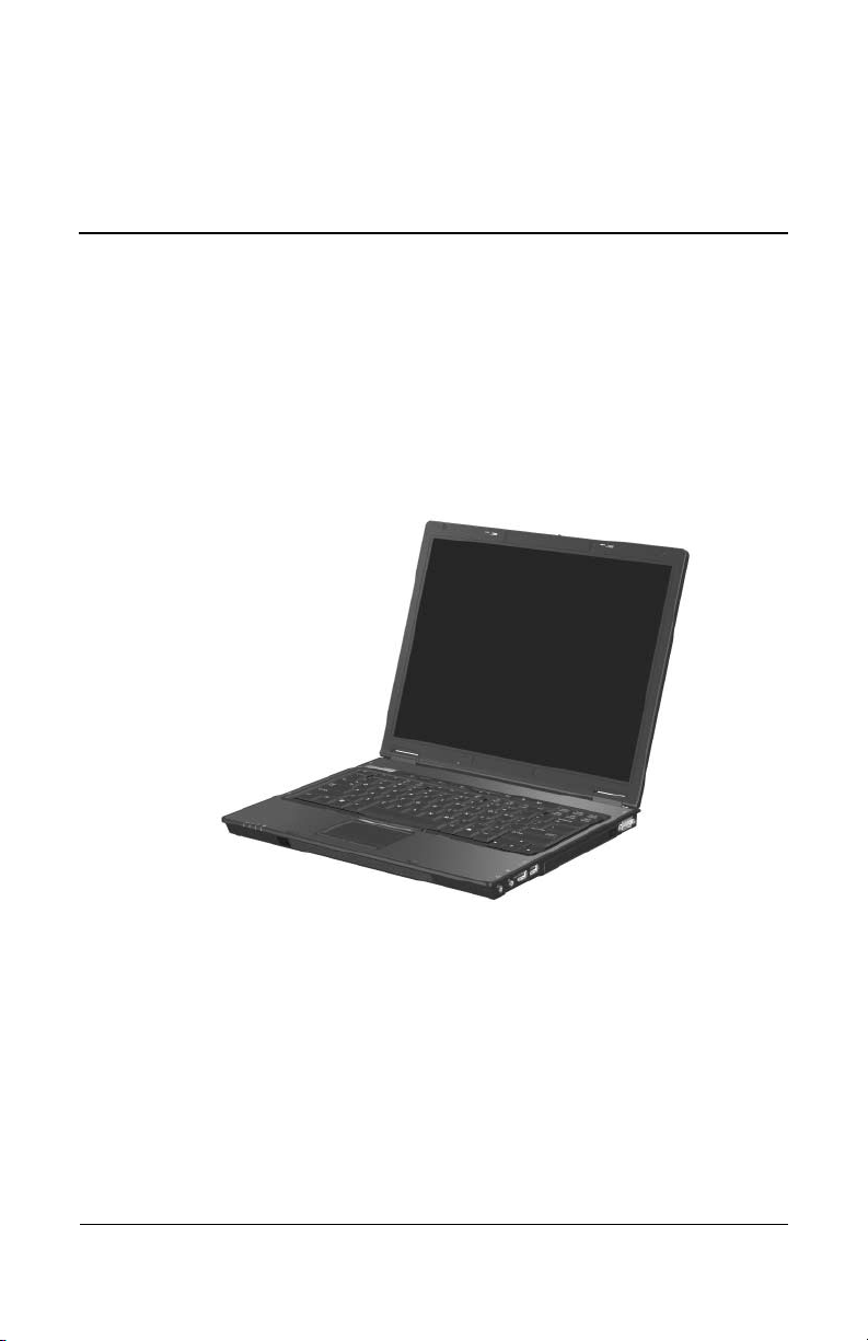
The HP Compaq nc6220 and nc6230 Notebook PCs offer
advanced modularity, Intel® Pentium® M and Celeron® M
processors, and extensive multimedia support.
1
HP Compaq nc6220 and nc6230 Notebook PCs
Maintenance and Service Guide 1–1
Page 6

Product Description
1.1 Features
■ The following processors are available, varying by
notebook
❏ Intel Pentium M 770 (2.13-GHz)
❏ Intel Pentium M 760 (2.00-GHz)
❏ Intel Pentium M 750 (1.86-GHz)
❏ Intel Pentium M 740 (1.73-GHz)
❏ Intel Pentium M 730 (1.60-GHz)
❏ Intel Celeron M 1.50-GHz)
■ The following displays are available, varying by
notebook
❏ 14.1-inch, SXGA, TFT (1400 × 1050) with over
❏ 14.1-inch, XGA, TFT (1280 × 800) with over 16.8 million
■ The following high-capacity hard drives are available,
varying by notebook model:
❏ 60-GB (7200-rpm)
❏ 80-GB, 60-GB, 40-GB (5400-rpm)
■ 256-MB DDR2 synchronous DRAM (SDRAM) at 400 and
533 MHz, expandable to 2.0 GB
■ Microsoft® Windows® XP Home Edition or Windows XP
Professional, varying by notebook model
■ Full-size Windows keyboard with embedded numeric keypad
■ TouchPad pointing device, including a dedicated vertical
scroll region
■ Integrated 10Base-T/100Base-TX Ethernet local area
network (LAN) network interface card (NIC) with RJ-45 jack
■ Integrated high-speed 56K modem with RJ-11 jack
■ Integrated wireless support for Mini PCI IEEE 802.11a/b/g or
802.11b/g WLAN device
model:
model:
million colors
16.8
colors
1–2 Maintenance and Service Guide
Page 7

Product Description
■ Support for one Type I or Type II PC Card slot, with support
both 32-bit (CardBus) and 16-bit PC Cards, varying by
for
notebook model
■ External 65-watt AC adapter with 3-wire power cord, varying
by notebook model
■ 6-cell Li-Ion battery pack
■ Stereo speakers
■ Volume up, volume mute, and volume down buttons
■ Support for the following optical drives:
❏ DVD-ROM Drive
❏ DVD+RW/R and CD-RW Combo Drive
❏ DVD/CD-RW Combo Drive
■ Connectors:
❏ Audio-out (headphone)
❏ Audio-in (microphone)
❏ Universal Serial Bus (USB) v. 2.0 (3 ports)
❏ Power
❏ External monitor
❏ RJ-11 (modem)
❏ RJ-45 (network)
❏ IEEE 1394
❏ Travel battery
❏ SD Card slot
❏ Smart card reader
❏ Infrared
❏ Parallel port
❏ S-Video-out
❏ Docking connector
Maintenance and Service Guide 1–3
Page 8

Product Description
1.2 Resetting the Notebook
If the notebook you are servicing has an unknown password,
follow these steps to clear the password. These steps also
CMOS:
clear
1. Prepare the notebook for disassembly (refer to Section 5.3,
“Preparing the Notebook for Disassembly,” for more
information).
2. Remove the real-time clock (RTC) battery (refer to
Section 5.24, “System Board,” for more information on
removing and replacing the RTC battery).
3. Wait approximately 5 minutes.
4. Replace the RTC battery and reassemble the notebook.
5. Connect AC power to the notebook. Do not reinsert any
battery packs at this time.
6. Turn on the notebook.
All passwords and all CMOS settings have been cleared.
1–4 Maintenance and Service Guide
Page 9

1.3 Power Management
The notebook comes with power management features that
extend battery operating time and conserve power. The
notebook
■ Standby
■ Hibernation
■ Setting customization by the user
■ Hotkeys for setting the level of performance
■ Battery calibration
■ Lid switch standby/resume
■ Power/standby button
■ Advanced Configuration and Power Management (ACPM)
supports the following power management features:
compliance
Product Description
Maintenance and Service Guide 1–5
Page 10
Product Description
1.4 External Components
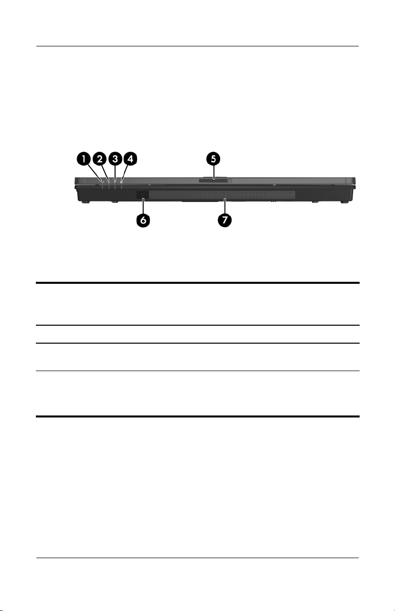
The external components on the front of the notebook are shown
below and described in
Front Components
Table 1-1.
Tabl e 1-1
Front Components
Item Component Function
1 Wireless light On: an integrated wireless device has been
turned on.
2 Power/standby light
1–6 Maintenance and Service Guide
■ On: Notebook is turned on.
■ Blinking: Notebook is in standby.
■ Off: Notebook is off.
Page 11

Tabl e 1-1
Product Description
Front Components
(Continued)
Item Component Function
3 Battery light Amber: A battery pack is charging.
Green: A battery pack is close to full charge
capacity.
Blinking amber: A battery pack that is the
only available power source has reached a
low-battery condition. When the battery
reaches a critical low-battery condition, the
battery light begins blinking more quickly.
Off: If the notebook is connected to an
external power source, the light is turned off
when all batteries in the notebook are fully
charged. If the notebook is not connected to
an external power source, the light is turned
off until the battery reaches a low-battery
condition.
4 Integrated Drive
Electronics (IDE) drive
light
5 Display release latch Opens the notebook.
6 Infrared port Provides wireless communication between
On: A drive in the hard drive bay or
MultiBay II is being accessed.
the notebook and an optional
IrDA-compliant device.
7 Speakers (2) Produce stereo sound.
Maintenance and Service Guide 1–7
Page 12
Product Description
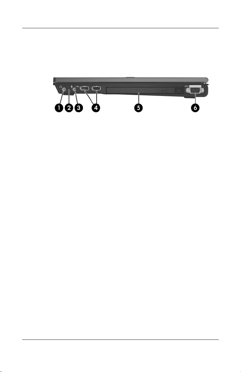
The external components on the right side of the notebook are
shown below and described in
Right-Side Components
Table 1-2.
1–8 Maintenance and Service Guide
Page 13

Tabl e 1-2
Product Description
Right-Side Components
Item Component Function
1 Audio-out
(headphone)
2 Internal microphone Records sound.
3 Audio-in
(microphone) jack
4 USB ports (2) Connects USB 1.1- and 2.0-compliant
5 MultiBay II Holds a MultiBay II device.
6 Serial port Connects an optional serial device.
jack
Produces system sound when connected to
optional powered stereo speakers,
headphones, headset, or television audio.
Connects an optional microphone.
devices to the notebook using a standard
USB cable.
Maintenance and Service Guide 1–9
Page 14

Product Description
The external components on the left side of the notebook are
shown below and described in
Left-Side Components
Table 1-3.
Tabl e 1-3
Left-Side Components
Item Component Function
1 Security cable slot Attaches an optional security cable to the
2 RJ-45 (network) jack Connects a network cable.
3 RJ-11 (modem) jack Connects the modem cable.
1–10 Maintenance and Service Guide
notebook.
The purpose of security solutions is
Ä
to act as a deterrent. These solutions
do not prevent the product from
being mishandled or stolen.
Page 15

Tabl e 1-3
Product Description
Left-Side Components
(Continued)
Item Component Function
4 Vent Enables airflow to cool internal
components.
To prevent overheating, do
Ä
5 USB port Connects USB 1.1- and 2.0-compliant
devices to the notebook using a standard
USB cable.
6 PC Card slot Supports optional Type I or Type II
PC Cards.
7 PC Card eject button Ejects an optional PC Card from the
PC Card slot.
8 Smart card reader Accepts smart cards.
9 SD Card slot Accepts Secure Digital (SD) Memory
Cards.
obstruct vents. Using the
not
notebook on a soft surface, such as a
pillow, blanket, rug, or thick clothing,
may block airflow.
Maintenance and Service Guide 1–11
Page 16
Product Description
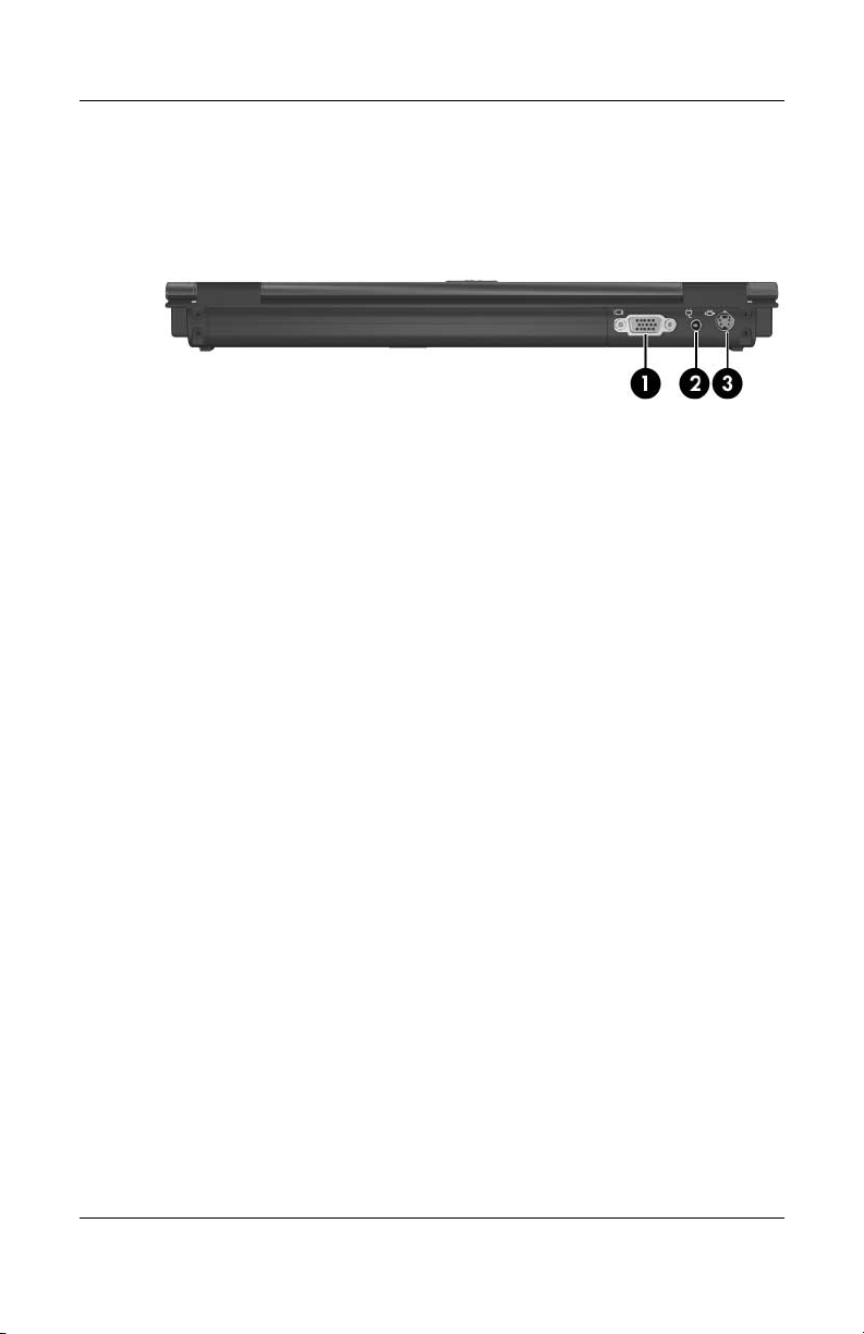
The external components on the rear panel of the notebook are
shown below and described in Table 1-4.
Rear Panel Components
1–12 Maintenance and Service Guide
Page 17

Product Description
Table 1-4
Rear Panel Components
Item Component Function
1 External monitor port Connects an optional external monitor or
overhead projector.
2 Power connector Connects an AC adapter or an optional
automobile or aircraft adapter.
3 S-Video-out jack Is a 7-pin, dual-purpose jack.
It connects an optional S-Video device
such as a television, VCR, camcorder,
overhead projector, or video capture card
by means of an optional, standard (4-pin)
S-Video cable.
The extra 3 pins also enable an optional
S-Video-to-composite adapter to be used
with the notebook.
Maintenance and Service Guide 1–13
Page 18
Product Description
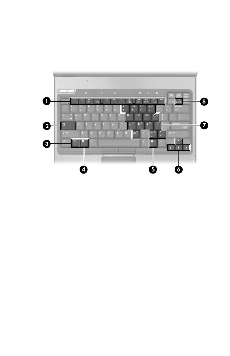
The standard keyboard components of the notebook are shown
below and described in Table 1-5.
Standard Keyboard Components
1–14 Maintenance and Service Guide
Page 19

Product Description
Table 1-5
Standard Keyboard Components
Item Component Function
1 f1 to f12 keys (12) Execute frequently used system functions
when pressed in combination with the fn
key.
2 caps lock key Enables caps lock and turns on the caps
3 fn key Executes frequently used system
4 Windows logo key Displays the Windows Start menu.
5 Windows
applications
6 Arrow keys Moves the cursor around the screen.
7 Embedded numeric
keypad
8 num lock key Enables numeric lock, turns on the
key
lock light.
functions when pressed in combination
with a function key or the
Displays a shortcut menu for items
beneath the pointer.
Can be used like the keys on an external
numeric keypad.
embedded numeric keypad, and turns
on
the num lock light.
esc key.
Maintenance and Service Guide 1–15
Page 20

Product Description
The notebook top components are shown below and described in
Table 1-6.
Top Components, Part 1
1–16 Maintenance and Service Guide
Page 21

Table 1-6
Top Components, Part 1
Item Component Function
1 Power/standby light On: The notebook is on.
2 Power/standby button When the notebook is:
■ Off, press and release to turn on the
notebook.
■ In standby, press and release to exit
standby.
■ In hibernation, press and release to
restore from hibernation.
If the system has stopped responding
Windows shutdown procedures
and
cannot be
for 5
used, press to the left and hold
seconds to turn off the notebook.
Product Description
3 Info Center button Enables you to view a list of commonly
4 Display switch Initiates standby if the display is closed
5 Wireless button
Wireless light
6 Presentation mode
button
7 Caps lock light On: caps lock is on.
8 Num lock light On: num lock is on or the embedded
9 Volume mute button Turns off the notebook sound.
Maintenance and Service Guide 1–17
used software solutions.
while the notebook is turned
Enables/disables the WLAN and
Bluetooth® devices.
On: An integrated wireless device is
hardware enabled.
Turns on Presentation mode.
numeric keypad is enabled.
on.
Page 22
Product Description
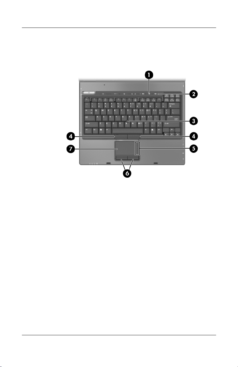
The notebook top components are continued below and described
in Table 1-7.
Top Components, Part 2
1–18 Maintenance and Service Guide
Page 23

Product Description
Table 1-7
Top Components, Part 2
Item Component Function
1 Volume down button Decreases notebook sound.
2 Volume up button Increases notebook sound.
3 Pointing stick Moves the pointer and selects or activates
4 Left/right pointing stick
buttons
5 TouchPad scroll zone Scrolls up or down.
6 Left/right TouchPad
buttons
7 TouchPad Moves the pointer and selects or activates
items on the screen.
Function like the left and right buttons on
an external mouse.
Function like the left and right buttons on
an external mouse.
items on the screen. Can be set to perform
other mouse functions, such as scrolling,
selecting, and double-clicking.
Maintenance and Service Guide 1–19
Page 24
Product Description
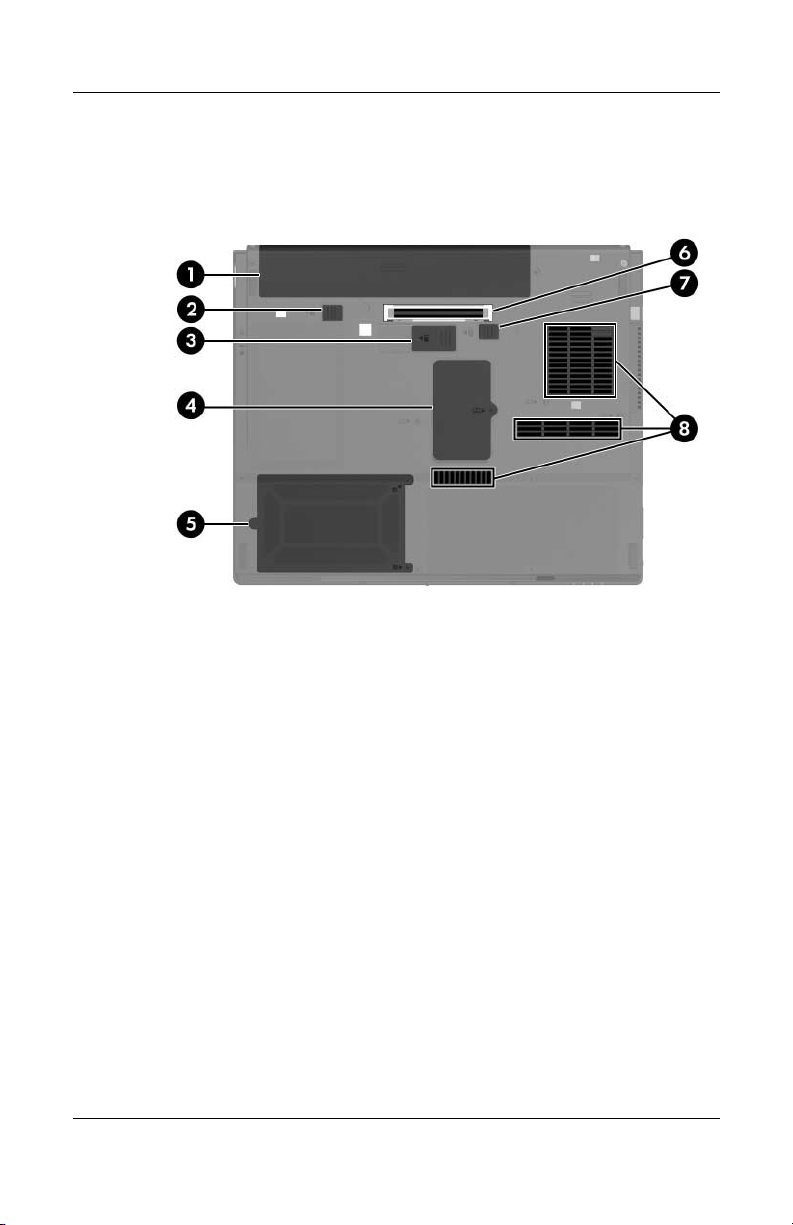
The external components on the bottom of the notebook are
shown below and described in
Bottom Components
Table 1-8.
1–20 Maintenance and Service Guide
Page 25

Table 1 -8
Product Description
Bottom Components
Item Component Function
1 Primary battery bay Holds the primary battery pack.
2 Primary battery locking
latch
3 Travel battery connector Connects an optional travel battery.
4 Expansion memory
module compartment
5 Hard drive bay Holds the primary hard drive.
6 Docking connector Connects the notebook to an optional
7 Primary battery release
latch
8 Vents (3) Enable airflow to cool internal
Secures the primary battery pack into
the battery bay.
Accepts one optional memory module.
docking device.
Releases the primary battery pack from
the battery bay.
components.
To prevent overheating, do
Ä
obstruct vents. Using the
not
notebook on a soft surface, such
as a pillow, blanket, rug, or thick
clothing, may block airflow.
Maintenance and Service Guide 1–21
Page 26

Product Description
1.5 Design Overview
This section presents a design overview of key parts and features
of the notebook. Refer to
to identify replacement parts, and Chapter 5, “Removal and
Replacement Procedures,” for disassembly steps.
The system board provides the following device connections:
■ Memory module
■ Mini PCI communications devices
■ Hard drive
■ Display
■ Keyboard and TouchPad
■ Audio
■ Intel Pentium M and Intel Celeron M processors
■ PC Card
CAUTION: To properly ventilate the notebook, allow at least a 7.6-cm
Ä
(3-inch) clearance on the left and right sides of the notebook.
Chapter 3, “Illustrated Parts Catalog,”
The notebook uses an electric fan for ventilation. The fan is
controlled by a temperature sensor and is designed to be turned
on automatically when high temperature conditions exist. These
conditions are affected by high external temperatures, system
power consumption, power management/battery conservation
configurations, battery fast charging, and software applications.
Exhaust air is displaced through the ventilation grill located on
the left side of the notebook.
1–22 Maintenance and Service Guide
Page 27

Troubleshooting
WARNING: Only authorized technicians trained by HP should repair
Å
this equipment. All troubleshooting and repair procedures are detailed
to allow only subassembly-/module-level repair. Because of the
complexity of the individual boards and subassemblies, do not attempt
to make repairs at the component level or modifications to any printed
wiring board. Improper repairs can create a safety hazard. Any
indication of component replacement or printed wiring board
modification may void any warranty or exchange allowances.
2.1 Computer Setup
Computer Setup is a system information and customization utility
that can be used even when the operating system is not working
or will not load. This utility includes settings that are not
available in Windows.
2
Using Computer Setup
Information and settings in Computer Setup are accessed from
the Main, Security, Advanced, or Tools menus:
1. Turn on or restart the notebook. Press f10 while the
= ROM-Based Setup message is displayed in
F10
lower-left corner of the screen.
the
❏ To change the language, use the cursor control keys
navigate to the Advanced menu.
to
❏ To view navigation information, press f1.
❏ To return to the Computer Setup menu, press esc.
Maintenance and Service Guide 2–1
Page 28

Troubleshooting
2. Select the Main, Security, Advanced, or Tools menu.
3. To close Computer Setup and restart the notebook:
❏ Select Exit > Exit Saving Changes, and then press enter.
- or -
❏ Select Exit > Exit Discarding Changes, and then
enter.
press
- or -
❏ Select Exit > Load Setup Defaults, and then press enter.
4. When you are prompted to confirm your action, press f10.
Selecting from the Main Menu
Table 2 -1
Main Menu
Select To Do This
System Information ■ Change the system time and system date.
■ View identification information about the
notebook.
■ View specification information about the
processor, memory and cache size, and
system ROM.
2–2 Maintenance and Service Guide
Page 29

Selecting from the Security Menu
Table 2 -2
Troubleshooting
Security Menu
Select To Do This
Administrator Password Enter, change, or delete an Administrator
password.
Power-on Password Enter, change, or delete a power-on password.
DriveLock Passwords Enable/disable DriveLock; change a DriveLock
user or master password.
DriveLock Settings are accessible only
✎
when you enter Computer Setup by turning
on (not restarting) the notebook.
Password Options
Password options
✎
Device Security Enable/disable:
selected only
can be
power-on
when a
password
been set.
has
Enable/disable:
■ QuickLock
■ QuickLock on Standby
■ QuickBlank
To enable QuickLock on Standby or
✎
QuickBlank, you must first enable
QuickLock.
■ Diskette drive startup*
■ CD-ROM or diskette startup
Settings for a DVD-ROM can be entered
✎
the CD-ROM field.
in
*Not applicable to SuperDisk LS-120 drives.
Maintenance and Service Guide 2–3
Page 30

Troubleshooting
Selecting from the Advanced Menu
Table 2 -3
Advanced Menu
Select To Do This
Language Change the Computer Setup language.
Boot Order Enable/disable MultiBoot, which sets a startup
sequence that can include most bootable devices
and media in the system.
Accessibility Options Allows electronic and information technology to
accessible to people with varying ranges of
be
abilities.
Video Memory Displays the amount of video memory available
on the notebook.
Selecting from the Tools Menu
Table 2 -4
Tools M enu
Select To Do This
Hard Drive Self Test Run a quick comprehensive self test on hard
drives in the system that support the test features.
2–4 Maintenance and Service Guide
Page 31

2.2 Troubleshooting Flowcharts
Tabl e 2-5
Troubleshooting
Troubleshooting Flowcharts Overview
Flowchart Description
2.1 “Flowchart 2.1—Initial Troubleshooting”
2.2 “Flowchart 2.2—No Power, Part 1”
2.3 “Flowchart 2.3—No Power, Part 2”
2.4 “Flowchart 2.4—No Power, Part 3”
2.5 “Flowchart 2.5—No Power, Part 4”
2.6 “Flowchart 2.6—No Video, Part 1”
2.7 “Flowchart 2.7—No Video, Part 2”
2.8 “Flowchart 2.8—Nonfunctioning Docking Device (if applicable)”
2.9 “Flowchart 2.9—No Operating System (OS) Loading”
2.10 “Flowchart 2.10—No OS Loading, Hard Drive, Part 1”
2.11 “Flowchart 2.11—No OS Loading, Hard Drive, Part 2”
2.12 “Flowchart 2.12—No OS Loading, Hard Drive, Part 3”
2.13 “Flowchart 2.13—No OS Loading, Diskette Drive”
Maintenance and Service Guide 2–5
Page 32

Troubleshooting
Tabl e 2-5
Troubleshooting Flowcharts Overview
Flowchart Description
2.14 “Flowchart 2.14—No OS Loading, Optical Drive”
2.15 “Flowchart 2.15—No Audio, Part 1”
2.16 “Flowchart 2.16—No Audio, Part 2”
2.17 “Flowchart 2.17—Nonfunctioning Device”
2.18 “Flowchart 2.18—Nonfunctioning Keyboard”
2.19 “Flowchart 2.19—Nonfunctioning Pointing Device”
2.20 “Flowchart 2.20—No Network/Modem Connection”
(Continued)
2–6 Maintenance and Service Guide
Page 33
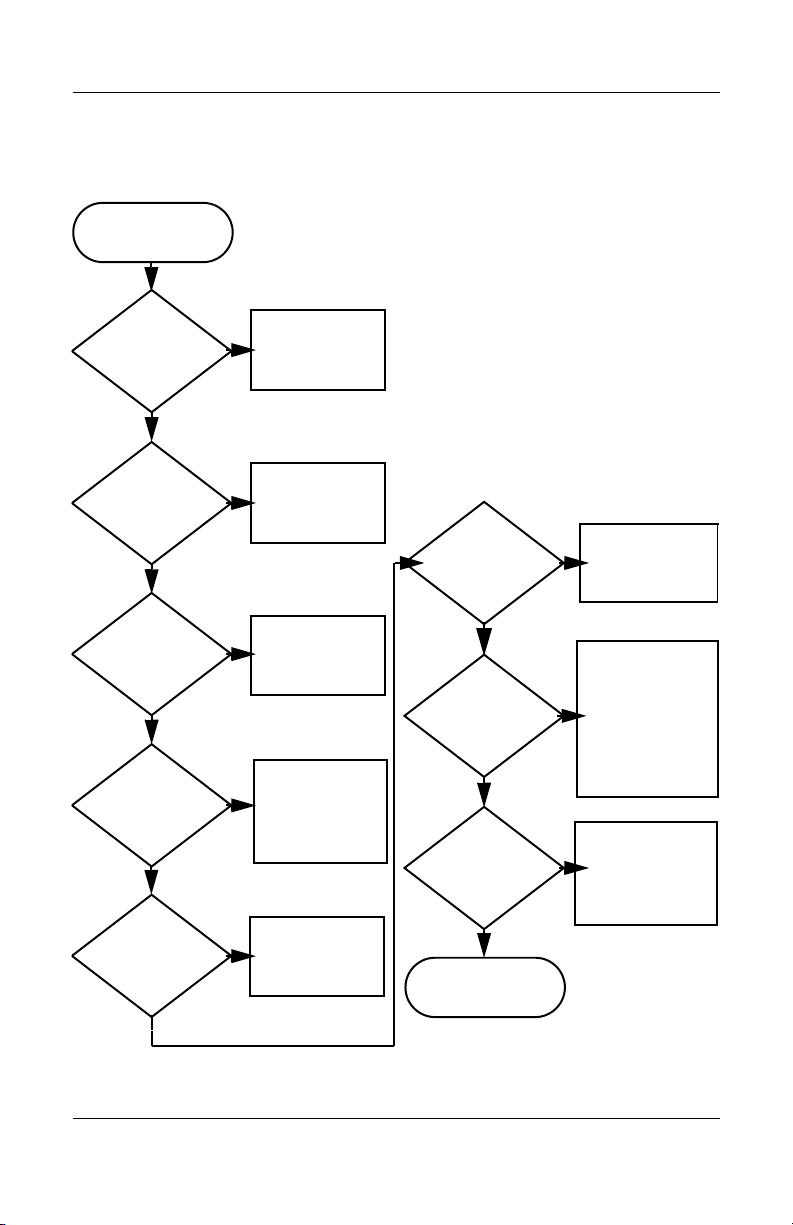
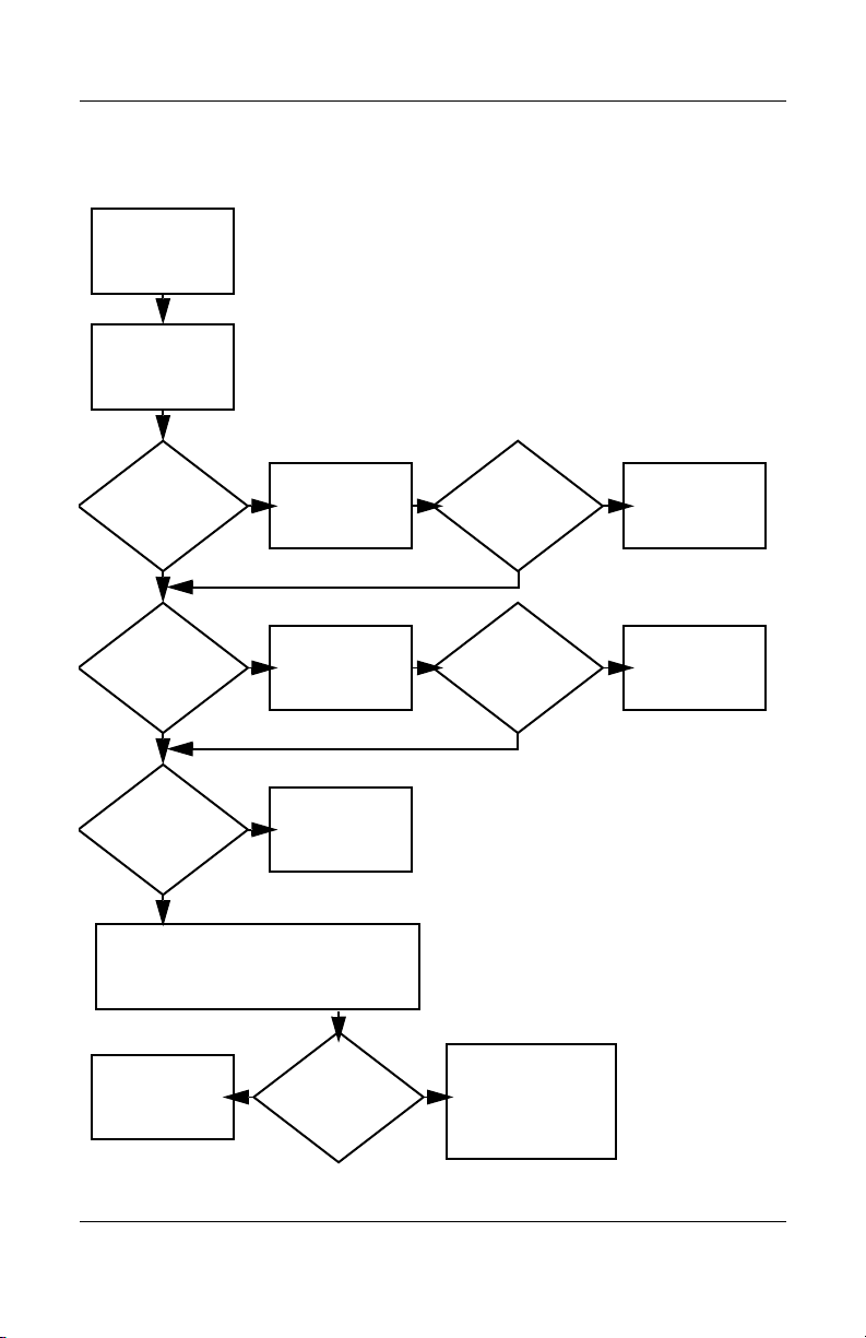
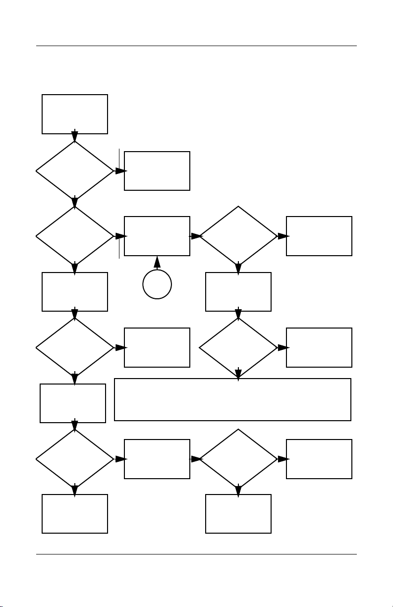
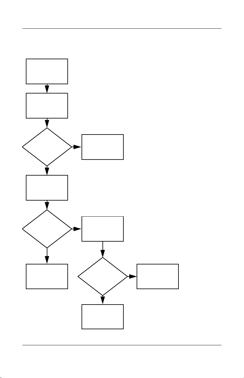
Flowchart 2.1—Initial Troubleshooting
Begin
troubleshooting.
N
Go to
Is there
power?
Y
N
Beeps,
LEDs, or error
messages?
Y
N
Is there video?
(no boot)
Y
N
Is the OS
loading?
Y
N
Is there
sound?
Y
“Flowchart
2.2—No Power,
Par t 1.”
Check
LED board,
speaker
connections.
Go to
“Flowchart
2.6—No Video,
Part 1.”
Go to
“Flowchart
2.9—No Operating
System (OS)
Loading.”
Go to
“Flowchart
2.15—No Audio,
Par t 1.”
N
All drives
working?
Y
N
Keyboard/
pointing
device
working?
Y
N
Connecting
to network
or modem?
Y
End
Troubleshooting
Go to
“Flowchart
2.17—Nonfunction
ing Device.”
Go to
“Flowchart
2.18—Nonfunction
ing Keyboard”
“Flowchart
2.19—Nonfunction
ing Pointing
Device.”
Go to
“Flowchart
2.20—No
Network/Modem
Connection.”
or
Maintenance and Service Guide 2–7
Page 34
Troubleshooting
N
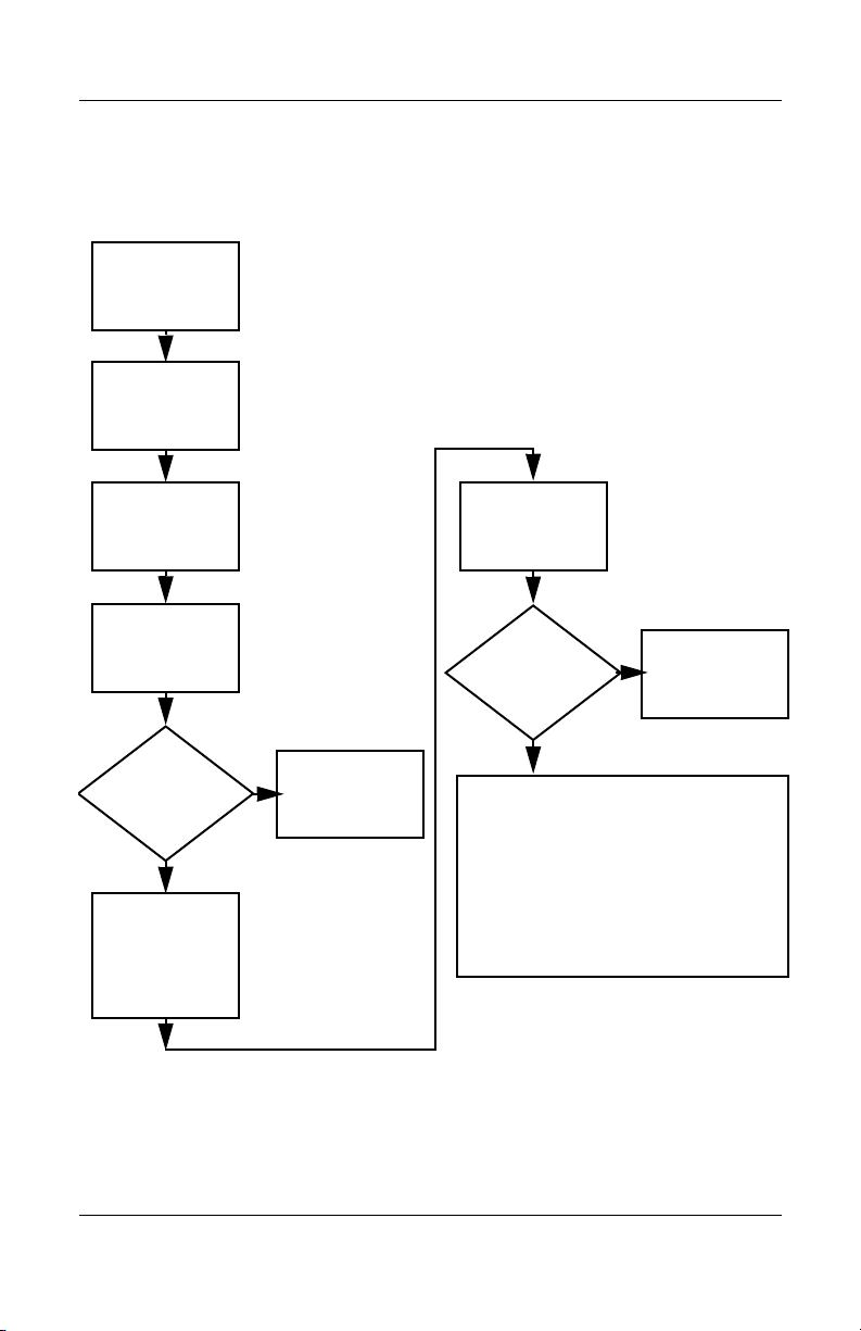
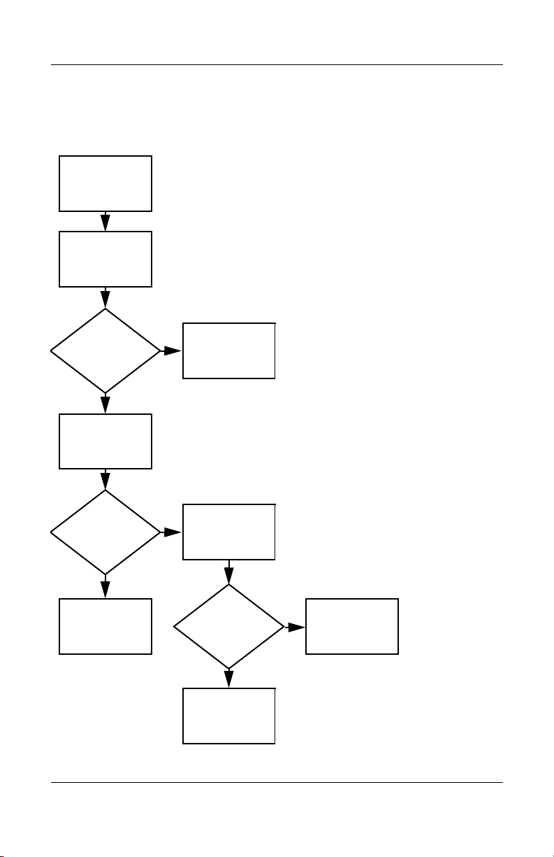
Flowchart 2.2—No Power, Part 1
No power
(power LED
is off).
Remove from
docking device
(if applicable).
Y
Y
Power up
on battery
power?
Power up
on AC
power?
N
Reset
power.*
Power up
on battery
power?
Y
N
Reset
power.*
Power up
on AC power?
Y
N
Go to
“Flowchart
2.3—No Power,
Par t 2.”
N
Go to
“Flowchart
2.4—No Power,
Part 3.”
Y
Power up in
docking
device?
1. Reseat the power cables in the docking
device and at the AC outlet.
2. Ensure the AC power source is active.
3. Ensure that the power strip is working.
Done
YN
Done
Power up
in docking
device?
*NOTES
1. On select models, there is a separate
reset button.
2. On select models, the notebook can be
reset using the standby switch and
either the lid switch or the main power
switch.
Go to
“Flowchart
2.8—Nonfunctioning
Docking Device (if
applicable).”
2–8 Maintenance and Service Guide
Page 35
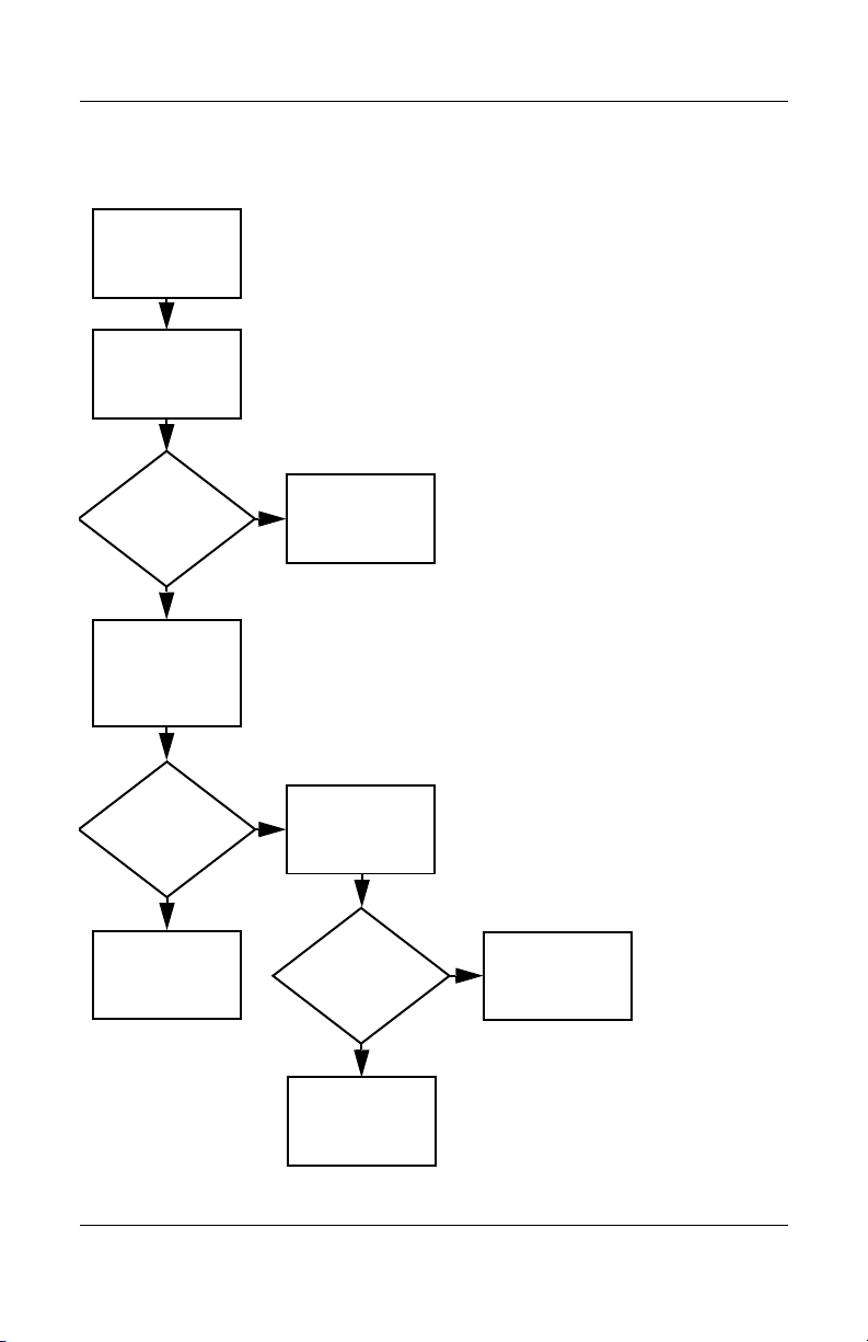
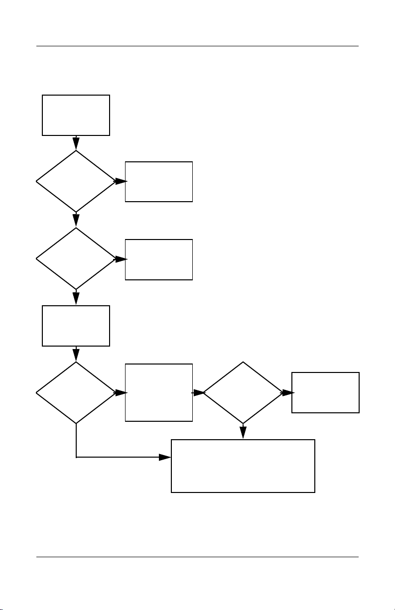
Flowchart 2.3—No Power, Part 2
N
Continued from
“Flowchart
2.2—No Power,
Par t 1.”
Visually check for
debris in battery
socket and clean
if necessary.
Y
Troubleshooting
Power on?
Check battery by
recharging it,
moving it to
another notebook,
or replacing it.
Done
N
Power on?
Replace
power supply
(if applicable).
Y
N
Go to
Done
Power on?
“Flowchart
2.4—No Power,
Part 3.”
Y
Done
Maintenance and Service Guide 2–9
Page 36
Troubleshooting
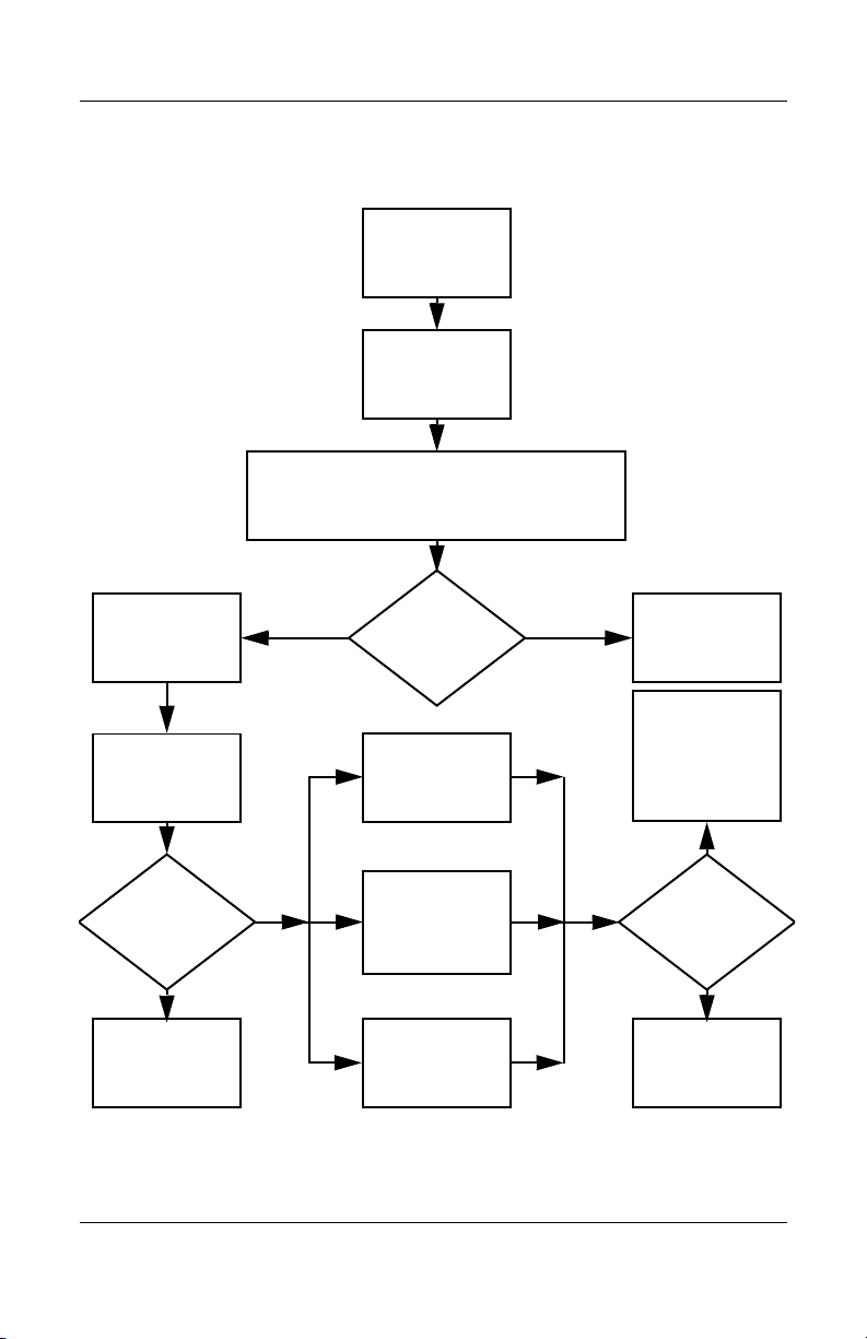
Flowchart 2.4—No Power, Part 3
Continued from
“Flowchart
2.3—No Power,
Part 2.”
Plug directly
into AC outlet.
Y
Power LED
on?
N
Reseat AC adapter
in notebook and
at power source.
Power on?
N
Power outlet
active?
Y
Replace
power cord.
Power on?
Done
Y
Done
External
N
Try different
outlet.
Internal or
external AC
adapter?
Internal
Go to
“Flowchart
2.5—No Power,
Part 4.”
Replace external
AC adapter.
N
Power on?
Y
Y
Done
Done
N
2–10 Maintenance and Service Guide
Page 37
Flowchart 2.5—No Power, Part 4
Continued from
“Flowchart
2.4—No Power,
Par t 3.”
Open
notebook.
Troubleshooting
N
Y
Loose or
damaged
parts?
Close
notebook and
retest.
Power on?
Done
Y
Reseat loose
components and
boards and
replace damaged
items.
N
Replace the following items (if applicable). Check
notebook operation after each replacement:
1. Internal DC-DC converter*
2. Internal AC adapter
3. Processor board*
4. System board*
*NOTE: Replace these items as a set to prevent
shorting out among components.
Maintenance and Service Guide 2–11
Page 38
Troubleshooting
Flowchart 2.6—No Video, Part 1
No video.
Docking Device
Stand-alone
or docking
device?
Go to
“Flowchart
2.7—No Video,
Part 2.”
*NOTE: To change from internal to
external display, use the hotkey
combination.
Stand-alone
Internal or
external
display*?
External
Adjust
brightness.
Internal
Y
Video OK? Done
N
Check for bent
pins on cable.
N
Video OK?
Adjust
brightness.
Video OK? Done
N
A
Press lid
switch to ensure
operation.
Video OK? Done
N
Replace the following one at a time. Test after each replacement.
1. Cable between notebook and notebook display (if applicable)
2. Display
3. System board
Try
another
display.
Internal and
external
video OK?
Y
Y
N
Replace
system
board.
YY
Done
Done
2–12 Maintenance and Service Guide
Page 39

Flowchart 2.7—No Video, Part 2
Continued from
“Flowchart
2.6—No Video,
Part 1.”
Remove
notebook from
docking device,
if connected.
Troubleshooting
Adjust
display
brightness.
N
Video OK?
Y
Check that notebook is properly
seated in docking device, for
bent pins on cable, and for
monitor connection.
Y
Video OK?
N
Adjust external
monitor display.
Go to “A” in
“Flowchart
2.6—No Video,
Part 1.”
Done
Check brightness
of external
monitor.
Video OK?
N
Try another
external
monitor.
Internal
and external
video OK?
N
Go to
“Flowchart
2.8—Nonfunctioning
Docking Device (if
applicable).”
Y
Done
Y
Done
Maintenance and Service Guide 2–13
Page 40
Troubleshooting
Flowchart 2.8—Nonfunctioning Docking Device
(if applicable)
Nonfunctioning
docking device.
Reseat power
cord in docking
device and
power outlet.
Check voltage
setting on docking
device.
Reset monitor
cable connector at
docking device.
Docking
device
operating?
N
Remove
notebook, reseat
all internal parts,
and replace any
damaged items in
docking device.
Reinstall
notebook into
docking device.
Y
Docking
device
operating?
Y
Done
N
Replace the following docking device
components one at a time. Check notebook
operation after each replacement.
1. Power supply
2. I/O board
3. Backplane board
4. Switch box
5. Docking device motor mechanism
Done
2–14 Maintenance and Service Guide
Page 41

Troubleshooting
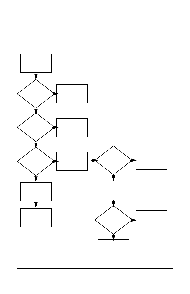
Flowchart 2.9—No Operating System (OS)
Loading
No OS
loading.*
Reseat power
cord in docking
device and
power outlet.
No OS loading from hard drive,
“Flowchart 2.10—No OS Loading,
go to
go to
Hard Drive, Part 1.”
No OS loading from diskette drive,
“Flowchart 2.13—No OS Loading,
Diskette Drive.”
No OS loading from optical drive,
“Flowchart 2.14—No OS Loading,
go to
“Flowchart 2.20—No Network/Modem
go to
*NOTE: Before beginning troubleshooting, always
check cable connections, cable ends, and drives
for bent or damaged pins.
Optical Drive.”
No OS loading from network,
Connection.”
Maintenance and Service Guide 2–15
Page 42

Troubleshooting
Flowchart 2.10—No OS Loading, Hard Drive,
Part 1
OS not
loading from
hard drive.
Nonsystem
disk message?
N
Reseat
external
hard drive.
OS loading?
N
Boot
from
CD?
Y
Check the Setup
utility for correct
booting order.
Boot
from
hard drive?
Y
Done
Y
Go to
“Flowchart
2.11—No OS
Loading,
Hard Drive, Part 2.”
Y
Done
N
N
Boot
from
diskette?
Y
N
Change boot
priority through
the Setup utility
and reboot.
Go to
“Flowchart
2.13—No OS
Loading,
Diskette Drive.”
N
Boot
from
hard drive?
2.17—Nonfunctioning
Go to
“Flowchart
Device.”
Y
2–16 Maintenance and Service Guide
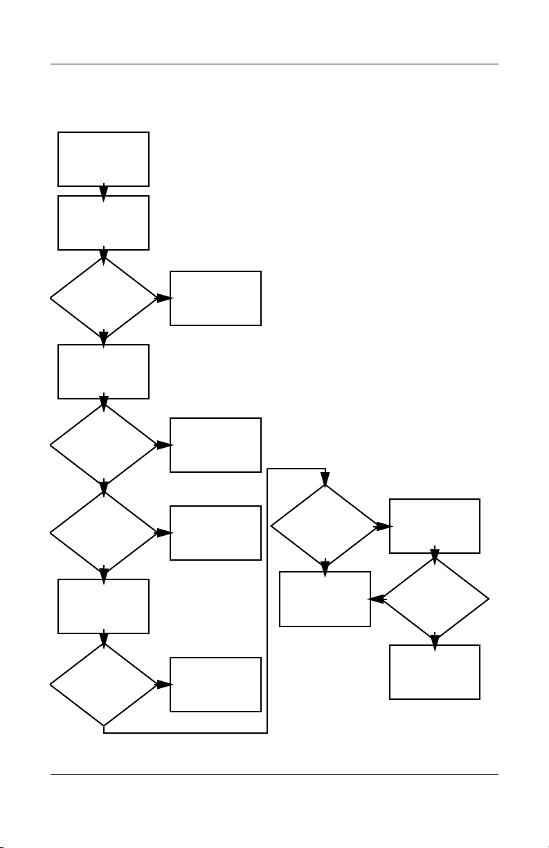
Page 43

Troubleshooting
Flowchart 2.11—No OS Loading, Hard Drive,
Part 2
Continued from
“Flowchart
2.10—No OS
Loading,
Hard Drive, Part 1.”
Disc or
diskette in
drive?
Y
Remove disc or
diskette and
reboot.
N
1. Replace
2. Replace system
hard drive.
board.
N
Reseat
hard drive.
Hard drive
accessible?
Run FDISK.
Y
Done
N
from diskette
Y
Boot
from
hard drive?
Boot
drive?
Y
N
Diskette Drive.”
Done
Go to
“Flowchart
2.13—No OS
Loading,
Hard drive
partitioned?
Y
Hard drive
formatted?
Y
N
Create partition,
and then format
hard drive to
bootable
C:\ prompt.
N
Format hard drive
and bring to
a bootable
C:\ prompt.
N
Y
Notebook
booted?
Load OS using
Operating System disc
(if applicable).
Y
Hard drive
accessible?
Done
N
Go to
“Flowchart
2.12—No OS
Loading,
Hard Drive, Part 3.”
Maintenance and Service Guide 2–17
Go to
“Flowchart
2.12—No OS
Loading,
Hard Drive, Part 3.”
Page 44

Troubleshooting
Flowchart 2.12—No OS Loading, Hard Drive,
Part 3
Continued from
“Flowchart
2.11—No OS
Loading,
Hard Drive, Part 2.”
N
System
files on hard
drive?
Y
Install OS
and reboot.
hard drive?
N
Run SCANDISK
and check for
bad sectors.
Can bad
sectors
be fixed?
Y
Fix bad
sectors.
Virus
on
Y
Clean virus.
loading from
hard drive?
Y
OS
Done
N
Y
Diagnostics on
disc or diskette?
Replace
hard drive.
N
N
Replace
hard drive.
Run diagnostics
and follow
recommendations.
N
Boot from
hard drive?
Replace
hard drive.
Y
Done
2–18 Maintenance and Service Guide
Page 45

Troubleshooting
N
N
Flowchart 2.13—No OS Loading, Diskette Drive
Y
OS not loading
from
diskette drive.
Reseat
diskette drive.
OS
loading?
Done
N
Nonsystem
disk message?
Y
Bootable
diskette
in drive?
N
Install bootable
diskette and
reboot notebook.
Y
N
Boot
from another
device?
Y
Go to
“Flowchart
2.17—Nonfunction
ing Device.”
N
Diskette
drive enabled
in the Setup
utility?
Enable drive
and cold boot
notebook.
Y
Y
Reset the notebook.
Is diskette
drive boot
order
correct?
Refer to
Section 1.2,
“Resetting the
Notebook,”
instructions.
for
Check diskette
for system files.
Try d iff er ent
diskette.
Nonsystem
disk error?
N
loading?
N
OS
Y
Replace the following
components
individually, retesting
after each
replacement:
■ Diskette drive
Y
Done
Change boot
priority using
the Setup utility.
2.17—Nonfunctioning
Go to
“Flowchart
Device.”
Maintenance and Service Guide 2–19
Page 46

Troubleshooting
Flowchart 2.14—No OS Loading, Optical Drive
loading from
CD-ROM or
DVD-ROM drive.
Boots from
CD or DVD?
N
Reseat
No OS
drive.
N
bootable disc.
Disc
in drive?
Install
Y
Bootable
disc in
drive?
Y
Try another
bootable disc.
N
Install bootable
disc and
reboot
notebook.
Y
Done
Y
Boots from
CD or DVD?
Done
N
Y
Booting
from another
device?
N
2.17—Nonfunctioning
Go to
“Flowchart
Device.”
Reset the notebook.
Booting
correct?
N
Correct boot
order using
the Setup utility.
order
Y
Refer to
Section 1.2,
“Resetting the
Notebook,”
instructions.
for
2.17—Nonfunctioning
Go to
“Flowchart
Device.”
2–20 Maintenance and Service Guide
Page 47

Flowchart 2.15—No Audio, Part 1
N
Turn up audio
No audio.
internally or
externally.
Audio? Done
N
Troubleshooting
Y
Notebook in
docking device
(if applicable)?
Y
Undock
Internal
audio?
N
Go to
“Flowchart
2.16—No Audio,
Par t 2.”
Y
Go to
“Flowchart
2.16—No Audio,
Par t 2.”
Replace the following docking device
components one at a time, as applicable.
Check audio status after each change.
1. Reseat docking device audio cable.
2. Replace audio cable.
3. Replace speaker.
4. Replace docking device audio board.
5. Replace backplane board.
6. Replace I/O board.
Y
Go to
“Flowchart
2.17—Nonfunctioning
Device.”
Audio? Done
N
Maintenance and Service Guide 2–21
Page 48
Troubleshooting
Flowchart 2.16—No Audio, Part 2
Continued from
“Flowchart
2.15—No Audio,
Part 1.”
N
Audio
driver in OS
configured?
Y
N
Correct
drivers for
application?
Y
Connect to
external
speaker.
Reload
audio drivers.
Load drivers and
set configuration
in OS.
Replace audio
board and
Audio?
YN
speaker
connections
in notebook
(if applicable).
Audio? Done
Replace the following components
individually, retesting after each
replacement:
YN
■ Internal speakers.
■ Audio board (if applicable).
2–22 Maintenance and Service Guide
Page 49
Flowchart 2.17—Nonfunctioning Device
Nonfunctioning
device.
Reseat
device.
Unplug the nonfunctioning device from the
notebook and inspect cables and plugs for bent
or broken pins or other damage.
Y
Clear
CMOS.
Reattach device.
Close notebook,
plug in power,
and reboot.
Any physical
device detected?
N
Replace hard drive.
Operating System
Troubleshooting
Fix or
replace
broken item.
Go to
“Flowchart
2.9—No
(OS) Loading.”
N
Device
boots
properly?
Y
Done
Replace NIC.
If integrated NIC,
replace system
board.
Y
Replace diskette
drive.
Maintenance and Service Guide 2–23
Device
boots
properly?
Done
N
Page 50
Troubleshooting
Flowchart 2.18—Nonfunctioning Keyboard
Keyboard
not operating
properly.
Connect notebook
to good external
keyboard.
N
Y
Reseat internal
connector
(if applicable).
Y
External
device
works?
keyboard
Replace
system
board.
N
Keyboard
operating
properly
Replace internal
keyboard or
cable.
Y
Keyboard
Done Done
operating
properly
N
Replace
system
board.
2–24 Maintenance and Service Guide
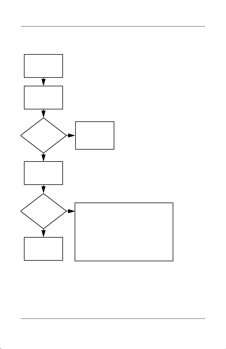
Page 51
Troubleshooting
Flowchart 2.19—Nonfunctioning Pointing
Device
Pointing device
not operating
properly.
Connect notebook
to good external
pointing device.
N
External
device
works?
Y
Reseat internal
pointing device
connector
(if applicable).
Replace
system
board.
N
Pointing device
operating
properly
Replace internal
pointing device
or cable.
Y
Y
Done Done
Pointing device
operating
properly
N
Replace
system
board.
Maintenance and Service Guide 2–25
Page 52
Troubleshooting
Flowchart 2.20—No Network/Modem
Connection
No network
or modem
connection.
N
Network
or modem jack
active?
Y
Y
Digital
line?
N
Replace jack
or have jack
activated.
Connect
to nondigital
line.
Y
Done
Y
Disconnect all
the notebook
NIC/modem
configured
in OS?
power from
and open.
N
Reload
drivers and
reconfigure.
Network
or modem
connection
working?
N
Replace NIC/modem
(if applicable).
Y
Reseat NIC/modem
(if applicable).
Network
or modem
connection
working?
Done
N
Replace
system
board.
2–26 Maintenance and Service Guide
Page 53
Illustrated Parts Catalog
This chapter provides an illustrated parts breakdown and a
reference for spare part numbers.
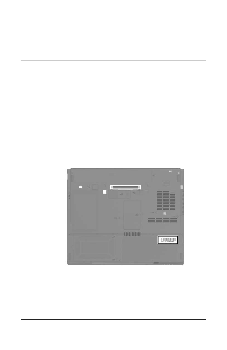
3.1 Serial Number Location
When ordering parts or requesting information, provide the
notebook serial number and model number located on the bottom
of the notebook.
3
Serial Number Location
Maintenance and Service Guide 3–1
Page 54
Illustrated Parts Catalog
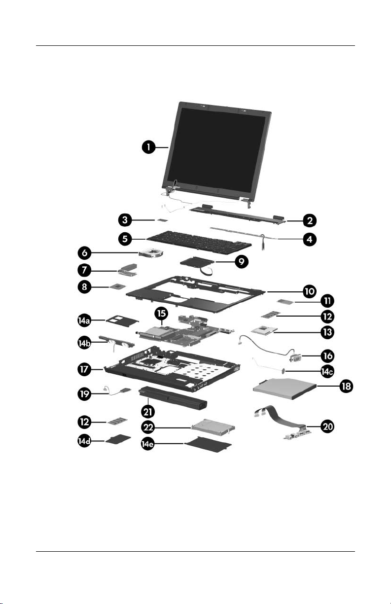
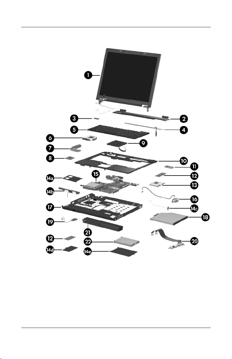
3.2 Notebook Major Components
Notebook Major Components
3–2 Maintenance and Service Guide
Page 55

Illustrated Parts Catalog
Table 3 -1
Spare Parts: Notebook Major Components
Spare Part
Item Description
1 Display assemblies (include wireless antenna boards and cables)
14.1-inch, SXGA, TFT
14.1-inch, XGA, TFT
2 Switch cover 379794-001
3 TPM security card 379807-001
4 LED board (includes LED board cable) 379795-001
5 Keyboards
Number
379793-001
379792-001
Belgium
Brazil
Czech Republic
Denmark
France
French Canada
Germany
Greece
Hungary
Iceland
International
Israel
Italy
Japan
Korea
378188-A41
378188-201
378188-221
378188-081
378188-051
378188-121
378188-041
378188-151
378188-211
378188-DD1
378188-021
378188-BB1
378188-061
378188-291
378188-AD1
Latin America
Norway
Portugal
Russia
Saudi Arabia
Slovakia
Slovenia
Spain
Sweden
Switzerland
Ta i wa n
Thailand
Tu r ke y
United Kingdom
United States
378188-161
378188-091
378188-131
378188-251
378188-171
378188-231
378188-BA1
378188-071
378188-101
378188-111
378188-AB1
378188-281
378188-141
378188-031
378188-001
Maintenance and Service Guide 3–3
Page 56
Illustrated Parts Catalog
Notebook Major Components
3–4 Maintenance and Service Guide
Page 57

Table 3 -1
Illustrated Parts Catalog
Spare Parts: Notebook Major Components
(Continued)
Spare Part
Item Description
6 Fan 378233-001
7 Heat sink (includes thermal paste) 379799-001
8 Processors (include thermal paste)
Intel Pentium M 770 (2.13-GHz)
Intel Pentium M 760 (2.00-GHz)
Intel Pentium M 750 (1.86-GHz)
Intel Pentium M 740 (1.73-GHz)
Intel Pentium M 730 (1.60-GHz)
Intel Celeron M 730 (1.5-GHz) 379801-001
9 TouchPad (includes TouchPad cable) 379798-001
10 Top cover 379796-001
11 Modem board 380774-001
12 Memory modules (PC2-3200, CL3)
1024 MB
512 MB
256 MB
Number
379806-001
379805-001
379804-001
379803-001
379802-001
373121-001
373120-001
373119-001
Maintenance and Service Guide 3–5
Page 58

Illustrated Parts Catalog
Notebook Major Components
3–6 Maintenance and Service Guide
Page 59

Table 3 -1
Illustrated Parts Catalog
Spare Parts: Notebook Major Components
Item Description
13 Mini PCI communications cards
802.11b/g combination WLAN card, for use
internationally
802.11b/g combination WLAN card, for use Japan
802.11b/g combination WLAN card, for use in
United States
the
802.11a/b/g combination WLAN card, for use in
Europe, Middle East, Africa
802.11a/b/g combination WLAN Mini PCI
communications card for use Japan
802.11a/b/g combination WLAN card, for use
internationally
802.11a/b/g combination WLAN card, for use Japan
802.11a/b/g combination WLAN card, for use in MOW
802.11a/b/g combination WLAN card, for use in
United States
the
802.11a/b/g High Band combination WLAN card
Miscellaneous Plastics Kit 379812-001
Includes:
14a
14b
14c
14d
14e
PC Card slot space saver
Speaker
RTC battery
Memory module compartment cover (includes 1 captive screw)
Hard drive cover (includes 2 captive screws)
Not illustrated:
Notebook feet
Base enclosure screw caps
Display bezel rubber caps
MultiBay II space saver
(Continued)
Spare Part
Number
373032-002
373032-291
373032-001
373900-021
373900-291
373033-002
373033-291
373900-001
373033-001
373901-001
Maintenance and Service Guide 3–7
Page 60

Illustrated Parts Catalog
Notebook Major Components
3–8 Maintenance and Service Guide
Page 61

Table 3 -1
Illustrated Parts Catalog
Spare Parts: Notebook Major Components
(Continued)
Spare Part
Item Description
15 System boards (include RJ-11 connector and cable)
Includes 64 MB of discrete video memory
Includes 32 MB of discrete video memory
Includes UMA video memory
16 Serial connector module (includes serial connector
module cable)
17 Base enclosure 379797-001
18 MultiBay II devices
8X Max DVD-ROM drive
DVD+RW/R and CD-RW Combo Drive
DVD/CD-RW Combo Drive
19 Broadcomm Bluetooth wireless board (includes
Bluetooth board cable)
20 Audio boards (include audio board cables)
For use with system boards with discrete video
memory
For use with system boards with UMA video memory
21 Battery packs
Number
382909-001
379790-001
379791-001
378227-001
373314-001
375557-001
373315-001
367871-001
385498-001
379811-001
6-cell, 4.8-AHr
6-cell, 4.8-AHr
8-cell, travel battery
22 Hard drives (include frame and connector)
7200-rpm
60-GB 380950-001
Maintenance and Service Guide 3–9
5400-rpm
80-GB
60-GB
40-GB
372772-001
367457-001
367456-001
379810-001
379809-001
379808-001
Page 62

Illustrated Parts Catalog
3.3 Miscellaneous Plastics Kit
Table 3-2
Spare Part Number 379812-001
Item Description
1 PC Card slot space saver
2 Speaker
3 RTC battery
4 Hard drive cover (includes 2 captive screws)
5 Memory module compartment cover (includes 1 captive screw)
6 Notebook feet (4)
7 Base enclosure rubber screw caps (2)
8 MultiBay II space saver
Not illustrated: Display bezel rubber caps
3–10 Maintenance and Service Guide
Page 63

Illustrated Parts Catalog
3.4 Miscellaneous Cables Kit
Tabl e 3-3
Spare Part Number 389013-001
Item
1 LED board cable
2 Bluetooth board cable
3 RJ-11 connector module with cable
4 Audio board cables (two, one for use on models with system boards
5 TouchPad cable
6 Serial connector board cable
Maintenance and Service Guide 3–11
Description
with discrete video memory, one for use on models with system
with UMA video memory)
boards
Not illustrated: Speaker cable (for use on models with system boards
with discrete video memory)
Page 64

Illustrated Parts Catalog
3.5 Mass Storage Devices
Tabl e 3-4
Spare Part Number Information
Spare Part
Item Description
1 Hard drives (include frame and connector)
7200-rpm
60-GB 380950-001
2 Optical drives (include bezel)
8X Max DVD-ROM drive
DVD+RW/R and CD-RW Combo Drive
DVD/CD-RW Combo Drive
3–12 Maintenance and Service Guide
5400-rpm
80-GB
60-GB
40-GB
Number
379810-001
379809-001
379808-001
373314-001
375557-001
373315-001
Page 65

Illustrated Parts Catalog
3.6 Miscellaneous (Not Illustrated)
Tabl e 3-5
Spare Part Information
Description
Adjustable notebook stand 372420-001
HP Advanced Docking Stand 374804-001
HP Docking Stand 374803-001
Docking Stand Miscellaneous Plastics Kit 380045-001
Carrying cases
Nylon top load
Nylon entry level
External MultiBay II 367621-001
External MultiBay II USB cable and stand 367622-001
External MultiBay II power cable 367870-001
USB 1.1 diskette drive 359118-001
Spare Part
Number
325815-001
and
325815-002
325814-001
Maintenance and Service Guide 3–13
Page 66

Illustrated Parts Catalog
Tabl e 3-5
Spare Part Information
Description
Power supplies
65 watt AC adapter
65 watt, slim profile AC adapter
Power cords
For use in:
Australia and New Zealand 246959-011
Belgium, Europe, Finland, France, Germany, Greece,
Netherlands, Norway, Portugal, Spain, and Sweden
the
Brazil 246959-201
Canada, French Canada, Latin America, Taiwan,
Thailand, and the United States
Denmark 246959-081
Hong Kong and the United Kingdom 246959-031
Israel 246959-BB1
Italy 246959-061
Japan 246959-291
(Continued)
Spare Part
Number
239704-001
381090-001
246959-021
246959-001
Korea 246959-AD1
Sweden 246959-AG1
3–14 Maintenance and Service Guide
Page 67

Tabl e 3-5
Illustrated Parts Catalog
Spare Part Information
Description
Screw Kit (includes the following screws; refer to
Appendix C, “Screw Listing,” for more information on
specifications and usage
■ Hex socket HM5.0×11.0 screw lock
■ Phillips PM2.5×13.0 spring-loaded
screw
■ Phillips PM2.5×4.0 screw
■ Phillips PM2.0x8.0 shoulder screw
■ Phillips PM2.0×8.0 screw
(Continued)
Spare Part
Number
379813-001
■ Phillips PM2.0×7.0 screw
■ Phillips PM2.0×4.0 screw
■ Phillips PM2.0x3.0 screw
■ Phillips PM1.5×8.0 screw
■ Phillips PM1.5×3.0 screw
■ Torx8 M2.0×8.0 screw
3.7 Sequential Part Number Listing
Table 3 -6
Spare Part
Number
Sequential Part Number Listing
Description
239704-001 65-watt AC adapter
246959-001 Power cord for use in Canada, French Canada, Latin America,
Taiwan, Thailand, and the United States
246959-011 Power cord for use in Australia and New Zealand
246959-021 Power cord for use in Belgium, Europe, Finland, France,
Germany, Greece, the
and Sweden
246959-031 Power cord for use in Hong Kong and the United Kingdom
246959-061 Power cord for use in Italy
Maintenance and Service Guide 3–15
Netherlands, Norway, Portugal, Spain,
Page 68

Illustrated Parts Catalog
Table 3 -6
Sequential Part Number Listing
(Continued)
Spare Part
Number Description
246959-081 Power cord for use in Denmark
246959-201 Power cord for use in Brazil
246959-291 Power cord for use in Japan
246959-AD1 Power cord for use in Korea
246959-AG1 Power cord for use in Sweden
246959-BB1 Power cord for use in Israel
325814-001 Nylon, entry-level top load carrying case
325815-001 Nylon top load carrying case
325815-002 Nylon top load carrying case
359118-001 USB 1.1 diskette drive
367456-001 8-cell, travel battery pack
367457-001 6-cell, 4.8-AHr battery pack
367871-001 Broadcomm Bluetooth wireless board (includes Bluetooth
board cable)
372420-001 Adjustable notebook stand
372772-001 6-cell, 4.8-AHr battery pack
373032-001 802.11b/g combination WLAN card, for use in
United States
the
373032-002 802.11b/g combination WLAN card, for use internationally
373032-291 802.11b/g combination WLAN card, for use Japan
373033-001 802.11a/b/g combination WLAN card, for use in
United States
the
373033-002 802.11a/b/g combination WLAN card, for use internationally
373033-291 802.11a/b/g combination WLAN card, for use Japan
3–16 Maintenance and Service Guide
Page 69

Table 3 -6
Illustrated Parts Catalog
Sequential Part Number Listing
(Continued)
Spare Part
Number Description
373119-001 256-MB memory module (PC2-3200, CL3)
373120-001 512-MB memory module (PC2-3200, CL3)
373121-001 1024-MB memory module (PC2-3200, CL3)
373314-001 8X Max DVD-ROM drive MultiBay II device
373315-001 DVD/CD-RW Combo Drive MultiBay II device
373900-001 802.11a/b/g combination WLAN card, for use in MOW
373900-021 802.11a/b/g combination WLAN card, for use in Europe,
Middle East, and Africa
373900-291 802.11a/b/g combination WLAN Mini PCI communications
card for use Japan
373901-001 802.11a/b/g High Band combination WLAN card
374803-001 HP Docking Station
374804-001 HP Advanced Docking Station
375557-001 DVD+RW/R and CD-RW Combo Drive MultiBay II device
378188-001 Keyboard for use in the United States
378188-021 Keyboard for use internationally
378188-031 Keyboard for use in the United Kingdom
378188-041 Keyboard for use in Germany
378188-051 Keyboard for use in France
378188-061 Keyboard for use in Italy
378188-071 Keyboard for use in Spain
378188-081 Keyboard for use in Denmark
378188-091 Keyboard for use in Norway
Maintenance and Service Guide 3–17
Page 70

Illustrated Parts Catalog
Table 3 -6
Sequential Part Number Listing
Spare Part
Number Description
378188-101 Keyboard for use in Sweden
378188-111 Keyboard for use in Switzerland
378188-121 Keyboard for use in French Canada
378188-131 Keyboard for use in Portugal
378188-141 Keyboard for use in Turkey
378188-151 Keyboard for use in Greece
378188-161 Keyboard for use in Latin America
378188-171 Keyboard for use in Saudi Arabia
378188-201 Keyboard for use in Brazil
378188-211 Keyboard for use in Hungary
378188-221 Keyboard for use in Czech Republic
378188-231 Keyboard for use in Slovakia
378188-251 Keyboard for use in Russia
378188-281 Keyboard for use in Thailand
378188-291 Keyboard for use in Japan
(Continued)
378188-A41 Keyboard for use in Belgium
378188-AB1 Keyboard for use in Taiwan
378188-AD1 Keyboard for use in Korea
378188-BA1 Keyboard for use in Slovenia
378188-BB1 Keyboard for use in Israel
378188-DD1 Keyboard for use in Iceland
378227-001 Serial connector module (includes cable)
3–18 Maintenance and Service Guide
Page 71

Table 3 -6
Illustrated Parts Catalog
Sequential Part Number Listing
(Continued)
Spare Part
Number Description
378233-001 Fan
379790-001 System board (includes 32 MB of discrete video memory and
RJ11 connector and cable)
379791-001 System board (includes UMA video memory and RJ11
connector and cable)
379792-001 14.1-inch, XGA, TFT display assembly (includes wireless
antenna boards and cables)
379793-001 14.1-inch, SXGA, TFT display assembly (includes wireless
antenna boards and cables)
379794-001 Switch cover
379795-001 LED board (includes LED board cable)
379796-001 Top cover
379797-001 Base enclosure
379798-001 TouchPad (includes TouchPad cable)
379799-001 Heat sink (includes thermal paste)
379801-001 Intel Celeron M 730 (1.5-GHz) processor (includes
thermal
paste)
379802-001 Intel Pentium M 730 (1.60-GHz) processor (includes
thermal
379803-001 Intel Pentium M 740 (1.73-GHz) processor (includes
thermal
379804-001 Intel Pentium M 750 (1.86-GHz) processor (includes
thermal
379805-001 Intel Pentium M 760 (2.00-GHz) processor (includes
thermal
Maintenance and Service Guide 3–19
paste)
paste)
paste)
paste)
Page 72

Illustrated Parts Catalog
Table 3 -6
Sequential Part Number Listing
(Continued)
Spare Part
Number Description
379806-001 Intel Pentium M 770 (2.13-GHz) processor (includes
thermal
379807-001 TPM security card
379808-001 5400-rpm 40-GB hard drive (includes frame and connector)
379809-001 5400-rpm 60-GB hard drive (includes frame and connector)
379810-001 5400-rpm 80-GB hard drive (includes frame and connector)
379811-001 Audio for use with system boards with UMA video memory
board (includes audio board cable)
379812-001 Miscellaneous Plastics Kit
379813-001 Screw Kit
380045-001 Docking Stand Miscellaneous Plastics Kit
380774-001 Modem board
380950-001 7200-rpm 60-GB hard drive (includes frame and connector)
381090-001 65 watt, slim profile AC adapter
382909-001 System board (includes 64 MB of discrete video memory and
RJ11 connector and cable)
paste)
385498-001 Audio board for use with system boards with discrete video
memory (includes audio board cable)
389013-001 Miscellaneous Cable Kit
3–20 Maintenance and Service Guide
Page 73

Removal and Replacement
This chapter provides essential information for proper and
removal and replacement service.
safe
4.1 Tools Required
You will need the following tools to complete the removal and
replacement procedures:
■ Magnetic screwdriver
■ Phillips P0 screwdriver
■ Torx T8 screwdriver
■ 5.0-mm socket for system board locks
■ Flat-bladed screwdriver
■ Tool kit—includes connector removal tool, loopback plugs,
and case utility tool
4
Preliminaries
Maintenance and Service Guide 4–1
Page 74

Removal and Replacement Preliminaries
4.2 Service Considerations
The following sections include some of the considerations
you should keep in mind during disassembly and assembly
that
procedures.
As you remove each subassembly from the notebook, place
✎
Plastic Parts
Cables and Connectors
Ä
subassembly (and all accompanying screws) away from
the
the work area to prevent damage.
Using excessive force during disassembly and reassembly can
damage plastic parts. Use care when handling the plastic parts.
Apply pressure only at the points designated in the maintenance
instructions.
CAUTION: When servicing the notebook, ensure that cables are
placed in their proper locations during the reassembly process.
Improper cable placement can damage the notebook.
Cables must be handled with extreme care to avoid damage.
Apply only the tension required to unseat or seat the cables
during removal and insertion. Handle cables by the connector
whenever possible. In all cases, avoid bending, twisting, or
tearing cables. Ensure that cables are routed in such a way that
they cannot be caught or snagged by parts being removed or
replaced. Handle flex cables with extreme care; these cables
easily.
tear
4–2 Maintenance and Service Guide
Page 75

Removal and Replacement Preliminaries
4.3 Preventing Damage to
Removable
Drives
Removable drives are fragile components that must be handled
with care. To prevent damage to the notebook, damage to a
removable drive, or loss of information, observe the following
precautions:
■ Before removing or inserting a hard drive, shut down the
notebook. If you are unsure whether the notebook is off or
hibernation, turn the notebook on, and then shut it down
in
through the operating system.
■ Before removing a diskette drive or optical drive, ensure that
diskette or disc is not in the drive and ensure that the optical
a
drive tray is closed.
■ Before handling a drive, ensure that you are discharged of
static electricity. While handling a drive, avoid touching the
connector.
■ Handle drives on surfaces covered with at least one inch of
shock-proof foam.
■ Avoid dropping drives from any height onto any surface.
■ After removing a hard drive, an optical drive, or a diskette
drive, place it in a static-proof bag.
■ Avoid exposing a hard drive to products that have magnetic
fields, such as monitors or speakers.
■ Avoid exposing a drive to temperature extremes or liquids.
■ If a drive must be mailed, place the drive in a bubble pack
mailer or other suitable form of protective packaging and label
the package “FRAGILE: Handle With Care.”
Maintenance and Service Guide 4–3
Page 76

Removal and Replacement Preliminaries
4.4 Preventing Electrostatic Damage
Many electronic components are sensitive to electrostatic
discharge (ESD). Circuitry design and structure determine the
degree of sensitivity. Networks built into many integrated circuits
provide some protection, but in many cases, the discharge
contains enough power to alter device parameters or melt
junctions.
silicon
A sudden discharge of static electricity from a finger or other
conductor can destroy static-sensitive devices or microcircuitry.
Often the spark is neither felt nor heard, but damage occurs.
An electronic device exposed to electrostatic discharge may not
be affected at all and can work perfectly throughout a normal
cycle. Or the device may function normally for a while, then
degrade in the internal layers, reducing its life expectancy.
4–4 Maintenance and Service Guide
Page 77

Removal and Replacement Preliminaries
4.5 Packaging and Transporting Precautions
Use the following grounding precautions when packaging and
transporting equipment:
■ To avoid hand contact, transport products in static-safe
containers, such as tubes, bags, or boxes.
■ Protect all electrostatic-sensitive parts and assemblies with
conductive or approved containers or packaging.
■ Keep electrostatic-sensitive parts in their containers until
parts arrive at static-free workstations.
the
■ Place items on a grounded surface before removing items
from their containers.
■ Always be properly grounded when touching a sensitive
component or assembly.
■ Store reusable electrostatic-sensitive parts from assemblies
protective packaging or nonconductive foam.
in
■ Use transporters and conveyors made of antistatic belts and
roller bushings. Ensure that mechanized equipment used for
moving materials is wired to ground and that proper materials
are selected to avoid static charging. When grounding is not
possible, use an ionizer to dissipate electric charges.
Maintenance and Service Guide 4–5
Page 78

Removal and Replacement Preliminaries
4.6 Workstation Precautions
Use the following grounding precautions at workstations:
■ Cover the workstation with approved static-shielding material
(refer to
■ Use a wrist strap connected to a properly grounded work
surface and use properly grounded tools and equipment.
■ Use conductive field service tools such as cutters, drivers, and
vacuums.
■ When fixtures must directly contact dissipative surfaces, use
fixtures made only of static-safe materials.
■ Keep the work area free of nonconductive materials such
as ordinary plastic assembly aids and Styrofoam.
■ Handle electrostatic-sensitive components, parts, and
assemblies by the case or PCM laminate. Handle these
items
■ Avoid contact with pins, leads, or circuitry.
■ Turn off power and input signals before inserting or removing
connectors or test equipment.
Table 4-2, “Static-Shielding Materials”).
only at static-free workstations.
4.7 Grounding Equipment and Methods
Grounding equipment must include either a wrist strap or a
strap at a grounded workstation.
foot
■ When seated, wear a wrist strap connected to a grounded
system. Wrist straps are flexible straps with a minimum of
megohm ±10% resistance in the ground cords. To provide
one
proper ground, wear a strap snugly against the skin at all times.
On grounded mats with banana-plug connectors, use alligator
clips to connect a wrist strap.
4–6 Maintenance and Service Guide
Page 79

Removal and Replacement Preliminaries
■ When standing, use foot straps and a grounded floor mat.
Foot straps (heel, toe, or boot straps) can be used at standing
workstations and are compatible with most types of shoes
boots. On conductive floors or dissipative floor mats, use
or
foot straps on both feet with a minimum of one megohm
resistance between the operator and ground. To be effective,
the conductive strips must be worn in contact with the skin.
Other grounding equipment recommended for use in preventing
electrostatic damage includes:
■ Antistatic tape
■ Antistatic smocks, aprons, and sleeve protectors
■ Conductive bins and other assembly or soldering aids
■ Nonconductive foam
■ Conductive tabletop workstations with ground cords of
one megohm resistance
■ Static-dissipative tables or floor mats with hard ties to
the ground
■ Field service kits
■ Static awareness labels
■ Material-handling packages
■ Nonconductive plastic bags, tubes, or boxes
■ Metal tote boxes
■ Electrostatic voltage levels and protective materials
Maintenance and Service Guide 4–7
Page 80

Removal and Replacement Preliminaries
Table 4-1 shows how humidity affects the electrostatic voltage
levels generated by different activities.
Tabl e 4-1
Typical Electrostatic Voltage Levels
Relative Humidity
Event 10% 40% 55%
Walking across carpet 35,000 V 15,000 V 7,500 V
Walking across vinyl floor 12,000 V 5,000 V 3,000 V
Motions of bench worker 6,000 V 800 V 400 V
Removing DIPS from plastic tube 2,000 V 700 V 400 V
Removing DIPS from vinyl tray 11,500 V 4,000 V 2,000 V
Removing DIPS from Styrofoam 14,500 V 5,000 V 3,500 V
Removing bubble pack from PCB 26,500 V 20,000 V 7,000 V
Packing PCBs in foam-lined box 21,000 V 11,000 V 5,000 V
A product can be degraded by as little as 700 V.
✎
Table 4-2 lists the shielding protection provided by antistatic
and floor mats.
bags
Table 4 -2
Static-Shielding Materials
Material Use Voltage Protection Level
Antistatic plastic Bags 1,500 V
Carbon-loaded plastic Floor mats 7,500 V
Metallized laminate Floor mats 5,000 V
4–8 Maintenance and Service Guide
Page 81

Removal and Replacement
This chapter provides removal and replacement procedures.
There are 56 screws and screw locks, in 12 different sizes, that
may need to be removed, replaced, or loosened when servicing
the notebook. Make special note of each screw and screw lock
size and location during removal and replacement.
Refer to Appendix C, “Screw Listing,” for detailed information
on screw and screw lock sizes, locations, and usage.
5.1 Serial Number
Report the notebook serial number to HP when requesting
information or ordering spare parts. The serial number is
located
on the bottom of the notebook.
5
Procedures
Serial Number Location
Maintenance and Service Guide 5–1
Page 82

Removal and Replacement Procedures
5.2 Disassembly Sequence Chart
Use the chart below to determine the section number to be
referenced when removing notebook components.
Disassembly Sequence Chart
Section Description
5.3 Preparing the notebook for
disassembly
Battery pack
5.4 Hard drive 2 loosened to remove the
5.5 Notebook feet 0
5.6 Bluetooth board 0
5.7 MultiBay II device 1
5.8 External memory module 1 loosened to remove the
5.9 Keyboard 3
5.10 Switch cover 3
5.11 LED board 5
5.12 TPM security card 1
5.13 Fan 2 loosened
# of Screws Removed
0
drive cover
hard
1 loosened to remove the
drive
hard
6 to disassemble hard drive
memory module
compartment cover
5.14 Heat sink 4 loosened
5–2 Maintenance and Service Guide
Page 83

Removal and Replacement Procedures
Disassembly Sequence Chart
Section Description
5.15 Processor 0
5.16 Modem board 2
5.17 Internal memory module 0
5.18 TouchPad 0
5.19 Mini PCI Communications Card 0
To prevent an unresponsive system and the display of a
Å
warning message, install only a Mini PCI device authorized
for use in your notebook by the governmental agency that
regulates wireless devices in your country. If you install a
device and then receive a warning message, remove the
device to restore notebook functionality. Then contact
Customer Care.
5.20 Display assembly 6
5.21 Top cover 11
5.22 Serial connector module 2 screw locks
5.23 Audio board 0
5.24 System board 2 screw locks
(Continued)
# of Screws Removed
4 screws
Maintenance and Service Guide 5–3
Page 84

Removal and Replacement Procedures
5.3 Preparing the Notebook for Disassembly
Before you begin any removal or installation procedures:
1. Shut down the notebook. If you are unsure whether the
notebook is off or in hibernation, turn the computer on,
then shut it down through the operating system.
and
2. Disconnect all external devices connected to the notebook.
3. Disconnect the power cord.
Battery Pack Spare Part Number Information
6-cell, 4.4-AHr
6-cell, 4.8-AHr
8-cell, travel battery
372772-001
367457-001
367456-001
5–4 Maintenance and Service Guide
Page 85
Removal and Replacement Procedures
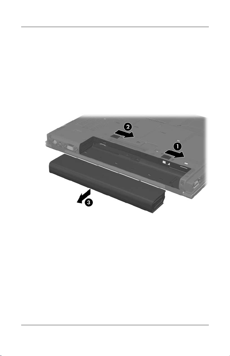
4. Remove the battery pack by following these steps:
a. Turn the notebook upside down with the rear panel
toward
you.
b. Slide and hold the battery pack lock latch 1 to the right.
c. Slide the battery pack release latch 2 to the right. (The
battery pack disengages from the notebook.)
d. Slide the battery pack straight back 3 and remove it.
Removing the Battery Pack
Reverse the above procedure to install the battery pack.
Maintenance and Service Guide 5–5
Page 86

Removal and Replacement Procedures
5.4 Hard Drive
Hard Drive Spare Part Number Information
7200-rpm
60-GB 380950-001
5400-rpm
80-GB
60-GB
40-GB
379810-001
379809-001
379808-001
1. Prepare the notebook for disassembly (refer to Section 5.3).
2. Position the notebook with the right side toward you.
5–6 Maintenance and Service Guide
Page 87
Removal and Replacement Procedures
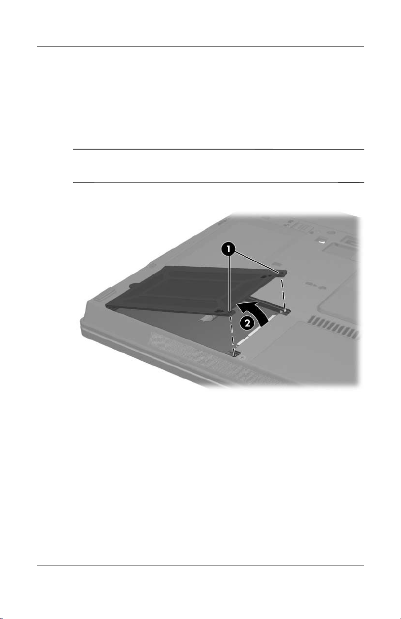
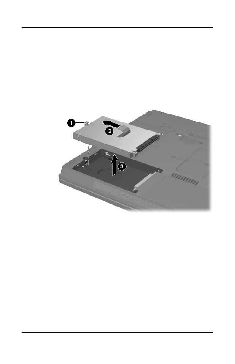
3. Loosen the 2 PM1.5×4.0 screws 1 that secure the hard drive
cover to the notebook.
4. Lift the right side of the hard drive cover and swing it to the
left 2.
5. Remove the hard drive cover.
The hard drive cover is included in the Miscellaneous
✎
Plastics Kit, spare part number 379812-001.
Removing the Hard Drive Cover
Maintenance and Service Guide 5–7
Page 88
Removal and Replacement Procedures
a. Loosen the PM2.5×13.0 spring-loaded hard drive
retention screw 1.
b. Grasp the mylar tab on the right side of the hard drive and
slide the hard drive to the left 2 to disconnect it from the
system board.
c. Remove the hard drive from the hard drive bay 3.
Removing the Hard Drive
5–8 Maintenance and Service Guide
Page 89
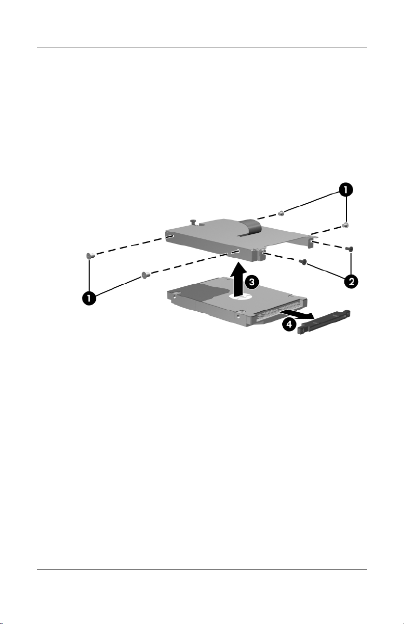
Removal and Replacement Procedures
d. Remove the 4 PM2.5×4.0 screws 1 and the 2 PM1.5×4.0
screws 2 that secure the hard drive frame to the hard
drive.
e. Lift the frame straight up 3 to remove if from the hard
drive.
f. Remove the hard drive connector 4 from the hard drive.
Removing the Hard Drive Frame and Connector
Reverse the above procedure to install and reassemble the
hard
drive.
Maintenance and Service Guide 5–9
Page 90

Removal and Replacement Procedures
5.5 Notebook Feet
The notebook feet are adhesive-backed rubber pads. The feet are
included in the Miscellaneous Plastics Kit, spare part number
379812-001.
Replacing the Notebook Feet
5–10 Maintenance and Service Guide
Page 91

5.6 Bluetooth Board
Bluetooth Board Spare Part Number Information
Removal and Replacement Procedures
Broadcomm Bluetooth wireless board (includes Bluetooth
cable)
board
1. Prepare the notebook for disassembly (refer to Section 5.3).
2. Position the notebook with the front panel toward you.
3. Slide the Bluetooth board out of the clip 1 in the hard drive
compartment.
4. Disconnect the Bluetooth board cable 2 from the board.
367871-001
Removing the Bluetooth Board
Reverse the above procedure to install a Bluetooth board.
Maintenance and Service Guide 5–11
Page 92

Removal and Replacement Procedures
5.7 MultiBay II Device
MultiBay II Device Spare Part Number Information
8X Max DVD-ROM drive
DVD+RW/R and CD-RW Combo Drive
DVD/CD-RW Combo Drive
1. Prepare the notebook for disassembly (Section 5.3).
2. Position the notebook with the right side toward you.
3. If it is installed, remove the PM2.0×5.0 security screw 1 that
secures the MultiBay II device to the notebook.
4. Gently press in on the left side of the device 2 to unlock it.
5. Slide the device 3 from the notebook.
373314-001
375557-001
373315-001
Removing the MultiBay II Device
Reverse the above procedure to install a MultiBay II device.
5–12 Maintenance and Service Guide
Page 93

Removal and Replacement Procedures
5.8 External Memory Module
Memory Module Spare Part Number Information
1024 MB
512 MB
256 MB
✎
373121-001
373120-001
373119-001
1. Prepare the notebook for disassembly (refer to Section 5.3).
2. Position the notebook with the front panel toward you.
3. Loosen the PM1.5×4.0 screw 1 that secures the memory
module compartment cover to the notebook.
4. Lift the right side of the cover up and swing it to the left 2.
5. Remove the memory module compartment cover.
The memory module compartment cover is included in the
Miscellaneous Plastics Kit, spare part number 379812-001.
Removing the Memory Module Compartment Cover
Maintenance and Service Guide 5–13
Page 94

Removal and Replacement Procedures
6. Spread the retaining tabs 1 on each side of the memory
module socket to release the memory module. (The side of
the memory module opposite the socket rises away from the
notebook.)
7. Slide the memory module away from the socket at an
2.
angle
8. Remove the memory module.
Note that memory modules are slotted 3 to prevent incorrect
✎
installation into the memory module socket.
Removing the Memory Module
Reverse the above procedure to install a memory module.
5–14 Maintenance and Service Guide
Page 95

5.9 Keyboard
Keyboard Spare Part Number Information
Removal and Replacement Procedures
Belgium
Brazil
Czech Republic
Denmark
France
French Canada
Germany
Greece
Hungary
Iceland
International
Israel
Italy
Japan
Korea
1. Prepare the notebook for disassembly (Section 5.3).
2. Turn the notebook upside down with the front panel
toward
378188-A41
378188-201
378188-221
378188-081
378188-051
378188-121
378188-041
378188-151
378188-211
378188-DD1
378188-021
378188-BB1
378188-061
378188-291
378188-AD1
you.
Latin America
Norway
Portugal
Russia
Saudi Arabia
Slovakia
Slovenia
Spain
Sweden
Switzerland
Ta i wa n
Thailand
Tu r ke y
United Kingdom
United States
378188-161
378188-091
378188-131
378188-251
378188-171
378188-231
378188-BA1
378188-071
378188-101
378188-111
378188-AB1
378188-281
378188-141
378188-031
378188-001
Maintenance and Service Guide 5–15
Page 96
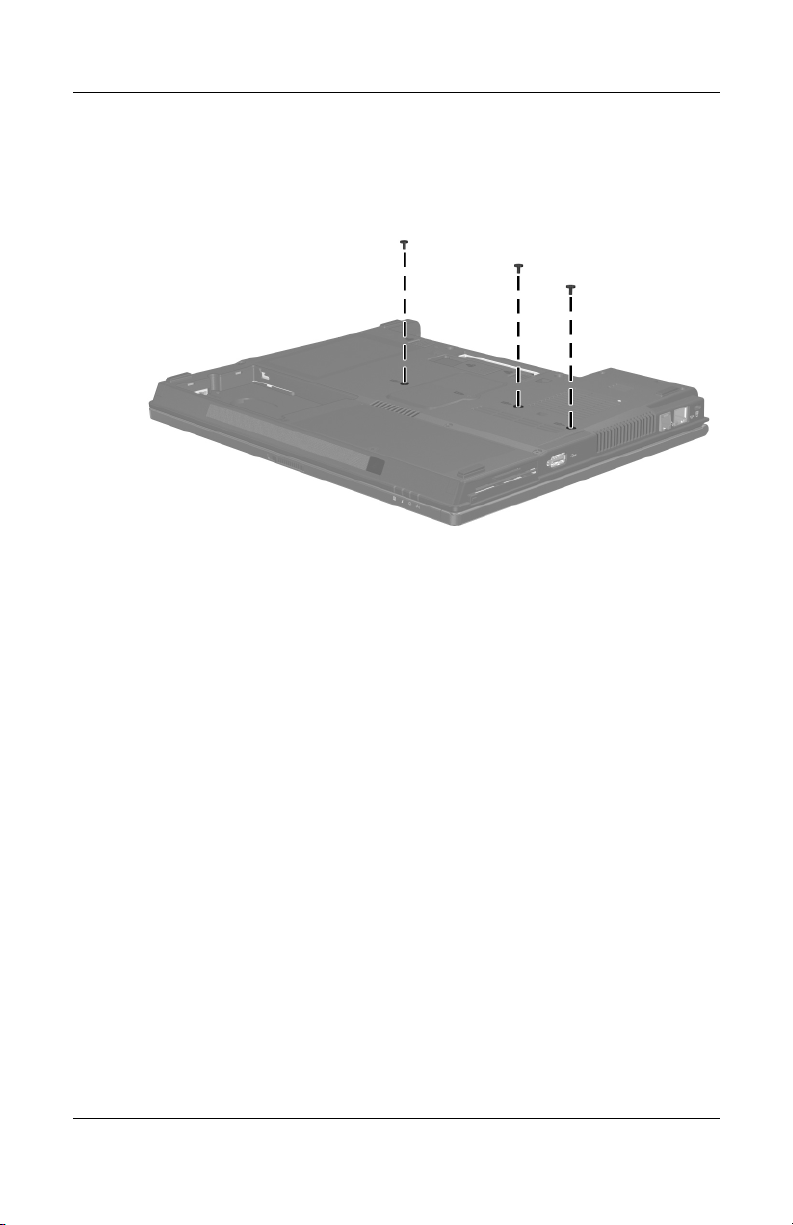
Removal and Replacement Procedures
3. Remove the 3 T8M2.0×8.0 screws that secure the keyboard to
the notebook.
Removing the Keyboard Screws
5–16 Maintenance and Service Guide
Page 97
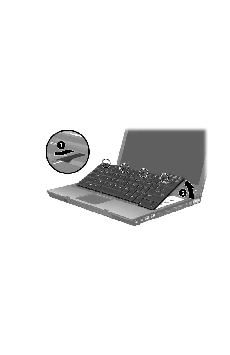
Removal and Replacement Procedures
4. Turn the notebook display-side up with the front panel toward
you.
5. Open the notebook as far as possible.
6. Slide the 4 keyboard retention tabs forward 1. The tabs are
located between the
keys, between the
delete keys.
esc and f1 keys, between the f4 and f5
f8 and f9 keys, and between the f12 and
7. Lift the rear edge of the keyboard and swing it forward until it
rests on the palm rest 2.
Releasing the Keyboard
Maintenance and Service Guide 5–17
Page 98
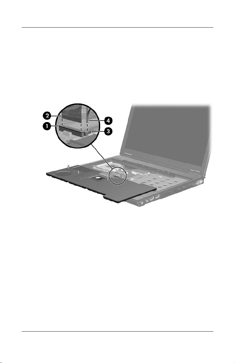
Removal and Replacement Procedures
8. Release the zero insertion force (ZIF) connector 1 to which
the keyboard cable is connected and disconnect the keyboard
cable 2 from the system board.
9. Release the ZIF connector 3 to which the pointing stick
cable is connected and disconnect the pointing stick cable 4
from the system board.
Disconnecting the Keyboard and Pointing Stick Cables
10. Remove the keyboard.
Reverse the above procedure to install the keyboard.
5–18 Maintenance and Service Guide
Page 99
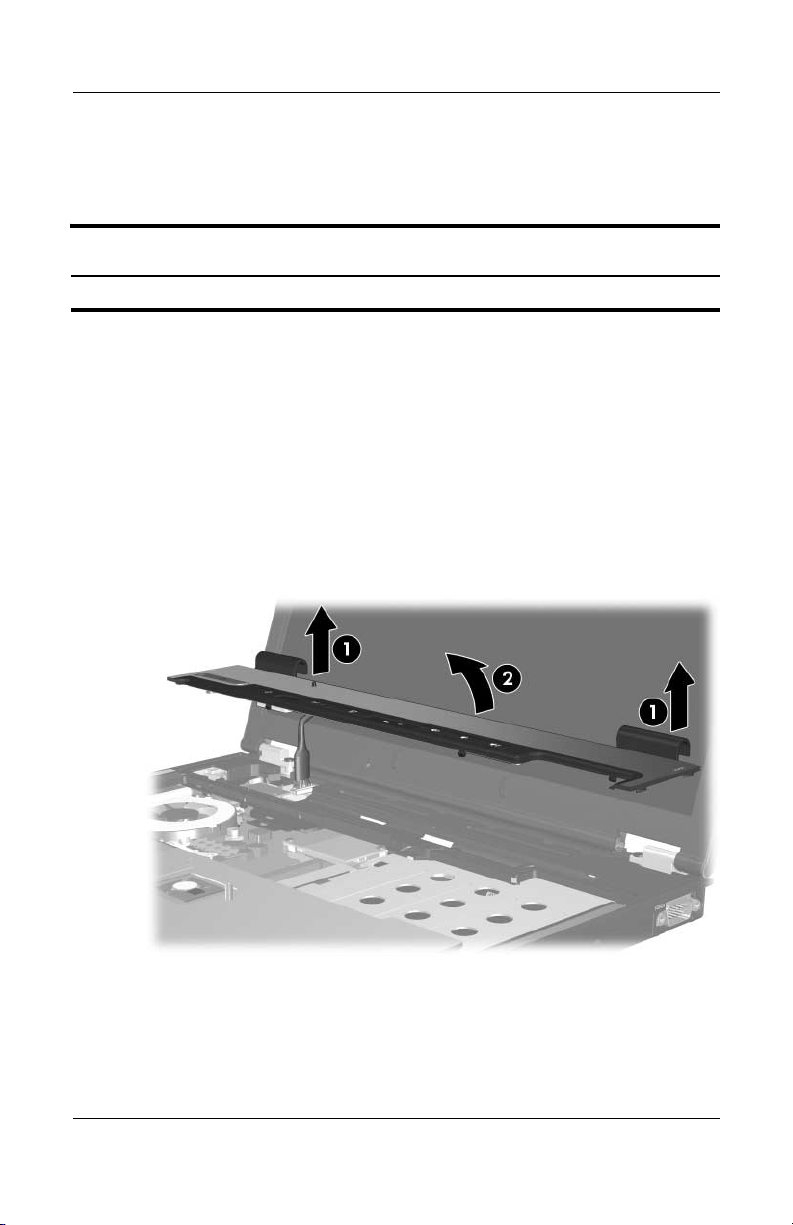
Removal and Replacement Procedures
5.10 Switch Cover
Switch Cover Spare Part Number Information
Switch cover 379794-001
1. Prepare the notebook for disassembly (Section 5.3).
2. Release the keyboard (Section 5.9).
3. Lift up the left and right hinge cover sections of the switch
cover 1 to detach the cover from the notebook.
4. Swing the rear edge of the hinge cover up and forward until
the cover rests on the notebook 2. (The LED board cable is
now visible at the upper-left edge of the notebook.)
Removing the Switch Cover
Maintenance and Service Guide 5–19
Page 100

Removal and Replacement Procedures
5. Disconnect the LED board cable from the system board.
Disconnecting the LED Board Cable
6. Remove the switch cover.
Reverse the above procedure to install the switch cover.
5–20 Maintenance and Service Guide
 Loading...