

Page 1

b
Hardware Guide
Compaq Evo™ Notebook N400c Series
Part Number: 231967-001
April 2001
This guide provides comprehensive information on setting up the
computer’s hardware and software, identifying computer
components, using the battery pack, connecting external devices,
and adding upgrades and accessories.
Page 2

© 2001 Compaq Computer Corporation.
Compaq, the Compaq logo, Armada, Deskpro Registered in U. S. Patent
and Trademark Office. Evo is a trademark of Compaq Information
Technologies Group, L.P. in the U.S. and other countries.
Microsoft, MS-DOS, Windows, W indows NT are trademarks of Microsoft
Corporation in the United States and other countries.
All other product names mentioned herein may be trademarks of their
respective companies.
Compaq shall not be liable for technical or editorial errors or omissions
contained herein. The information in this document is provided “as is”
without warranty of any kind and is subject to change without notice. the
warranties for Compaq products are set forth in the express limited
warranty statements accompanying such products. Nothing herein should
be construed as constituting an additional warranty.
Printed in the U.S.A.
Hardware Guide
First Edition (April 2001)
Part Number: 231967-001
Page 3

Contents
1 Hardware and Software Setup
Setting up the Hardware. . . . . . . . . . . . . . . . . . . . . . . . . . 1–1
Setting Up the Software. . . . . . . . . . . . . . . . . . . . . . . 1–6
After Software Setup . . . . . . . . . . . . . . . . . . . . . . . . . 1–7
2 A Look at the Computer
Front Panel Components . . . . . . . . . . . . . . . . . . . . . . . . . 2–1
Top Components . . . . . . . . . . . . . . . . . . . . . . . . . . . . . . . 2–2
Top Components (continued). . . . . . . . . . . . . . . . . . . . . . 2–4
Right Side Components . . . . . . . . . . . . . . . . . . . . . . . . . . 2–6
Left Side Components . . . . . . . . . . . . . . . . . . . . . . . . . . . 2–8
Bottom Components. . . . . . . . . . . . . . . . . . . . . . . . . . . . 2–10
Rear Panel Components. . . . . . . . . . . . . . . . . . . . . . . . . 2–12
Additional Standard Components . . . . . . . . . . . . . . . . . 2–13
3 Keyboard and Pointing Devices
Using the TouchPad (TouchPad Models) . . . . . . . . . . . . 3–1
Using the Pointing Stick (Pointing Stick Models). . . 3–2
Using Hotkeys and Shortcut Keys . . . . . . . . . . . . . . . . . . 3–3
Fn Key . . . . . . . . . . . . . . . . . . . . . . . . . . . . . . . . . . . . 3–3
Hotkeys . . . . . . . . . . . . . . . . . . . . . . . . . . . . . . . . . . . 3–4
Shortcut Keys . . . . . . . . . . . . . . . . . . . . . . . . . . . . . . 3–5
Hotkey and Shortcut Key Procedures . . . . . . . . . . . . 3–5
Using the Embedded Numeric Keypad . . . . . . . . . . . . . . 3–9
Enabling the Numeric Keypad . . . . . . . . . . . . . . . . . 3–9
Disabling the Numeric Keypad . . . . . . . . . . . . . . . . 3–10
Converting the Numeric Keypad Keys to
Hardware Guide iii
Page 4

Contents
Standard Keys . . . . . . . . . . . . . . . . . . . . . . . . . . . . . 3–10
Enabling the Numeric Keypad at Startup . . . . . . . . 3–10
Using the Easy Access Buttons . . . . . . . . . . . . . . . . . . . 3–11
4 Battery Packs
Charging Battery Packs . . . . . . . . . . . . . . . . . . . . . . . . . . 4–1
Using a New Battery Pack . . . . . . . . . . . . . . . . . . . . . . . . 4–2
Replacing a Battery Pack . . . . . . . . . . . . . . . . . . . . . . . . . 4–3
Replacing the Primary Battery Pack . . . . . . . . . . . . . 4–3
Replacing an Optional External Battery Pack. . . . . . 4–6
Storing a Battery Pack . . . . . . . . . . . . . . . . . . . . . . . . . . 4–10
Recycling a Used Battery Pack . . . . . . . . . . . . . . . . . . . 4–10
5 Drives
Caring for Drives . . . . . . . . . . . . . . . . . . . . . . . . . . . . . . . 5–1
Removing a Hard Drive. . . . . . . . . . . . . . . . . . . . . . . . . . 5–1
Inserting a Hard Drive . . . . . . . . . . . . . . . . . . . . . . . . . . . 5–6
Changing the Startup Sequence with MultiBoot . . . . . . . 5–6
Enabling Bootable Media and Devices for
MultiBoot. . . . . . . . . . . . . . . . . . . . . . . . . . . . . . . . . . 5–7
Using the Default Search Sequence. . . . . . . . . . . . . . 5–8
Planning Changes to the Startup Sequence . . . . . . . 5–10
Selecting a MultiBoot Utility . . . . . . . . . . . . . . . . . 5–10
Changing the Startup Sequence in
Computer Setup. . . . . . . . . . . . . . . . . . . . . . . . . . . . 5–11
Setting a Continuing Startup Sequence. . . . . . . . . . 5–11
Setting the MultiBoot Express Prompt . . . . . . . . . . 5 –12
Responding to the Express Boot Menu . . . . . . . . . . 5–12
Changing the Startup Sequence in
Compaq Computer Security . . . . . . . . . . . . . . . . . . 5–13
6 Audio and Video
Using Audio Features. . . . . . . . . . . . . . . . . . . . . . . . . . . . 6–1
Connecting a Stereo Speaker/Headphone . . . . . . . . . 6–2
Connecting a Microphone . . . . . . . . . . . . . . . . . . . . . 6–3
iv Hardware Guide
Page 5

Adjusting Volume . . . . . . . . . . . . . . . . . . . . . . . . . . . 6–3
Using Video Features. . . . . . . . . . . . . . . . . . . . . . . . . . . . 6–4
Connecting a Device to the Composite
Video-Out Jack . . . . . . . . . . . . . . . . . . . . . . . . . . . . . 6–5
Changing the Video Mode. . . . . . . . . . . . . . . . . . . . . 6–6
7 External Device Connections
Connecting an External Monitor . . . . . . . . . . . . . . . . . . . 7–1
Connecting a Video Device . . . . . . . . . . . . . . . . . . . . . . . 7–2
Connecting a Serial Printer . . . . . . . . . . . . . . . . . . . . . . . 7–2
Connecting a Parallel Printer . . . . . . . . . . . . . . . . . . . . . . 7–3
Connecting Infrared Equipment. . . . . . . . . . . . . . . . . . . . 7–3
Infrared Connection Guidelines. . . . . . . . . . . . . . . . . 7–4
Infrared Configuration Guidelines. . . . . . . . . . . . . . . 7–5
Enabling the Infrared Port . . . . . . . . . . . . . . . . . . . . . 7–5
Connecting USB Equipment . . . . . . . . . . . . . . . . . . . . . . 7–6
Attaching a Mobile Expansion Unit. . . . . . . . . . . . . . . . . 7–6
Connecting a Docking Base. . . . . . . . . . . . . . . . . . . . . . . 7–6
Connecting a Modem or NIC. . . . . . . . . . . . . . . . . . . . . . 7–7
Connecting to Wireless Devices . . . . . . . . . . . . . . . . . . . 7–7
Contents
8 Computer Upgrades and Add-ons
Before Removing or Installing Components . . . . . . . . . . 8–1
Upgrading Memory . . . . . . . . . . . . . . . . . . . . . . . . . . . . . 8–2
Removing and Inserting a Memory
Expansion Board . . . . . . . . . . . . . . . . . . . . . . . . . . . . 8–3
Removing A Memory Expansion Board . . . . . . . . . 8–10
Upgrading or Adding a Modem or NIC . . . . . . . . . 8–11
Adding and Using PC Cards . . . . . . . . . . . . . . . . . . . . . 8–16
Configuring a PC Card . . . . . . . . . . . . . . . . . . . . . . 8–16
Inserting a PC Card . . . . . . . . . . . . . . . . . . . . . . . . . 8–17
Removing a PC Card. . . . . . . . . . . . . . . . . . . . . . . . 8–18
Conserving Energy . . . . . . . . . . . . . . . . . . . . . . . . . 8–19
Installing Additional Device Drivers . . . . . . . . . . . . . . . 8–20
Attaching the Mobile Expansion Unit . . . . . . . . . . . . . . 8–20
Hardware Guide v
Page 6

Contents
Docking Bases . . . . . . . . . . . . . . . . . . . . . . . . . . . . . . . . 8–20
Using an External Diskette Drive . . . . . . . . . . . . . . . . . 8–21
Connecting the External Diskette Drive . . . . . . . . . 8–21
Disconnecting the External Diskette Drive . . . . . . . 8–22
Upgrading the Hard Drive . . . . . . . . . . . . . . . . . . . . . . . 8–22
Adding a Second Battery Pack. . . . . . . . . . . . . . . . . . . . 8–22
Adding Wireless Devices. . . . . . . . . . . . . . . . . . . . . . . . 8 –22
9 Specifications
Regulatory Agency Series Numbers . . . . . . . . . . . . . . . . 9 –1
Index
vi Hardware Guide
Page 7
Hardware and Software Setup
Setting up the Hardware
1. Record the Product Key for your operating system. It is
essential for the software setup. When you start the computer
for the first time, you may be prompted to enter the product
key. You also may need to enter it to update or troubleshoot
your operating system. The Product Key is located on the
Certificate of Authenticity label on the bottom of the
computer.
1
2. Place the computer on a flat surface near an electrical outlet.
Hardware Guide 1–1
Page 8

Hardware and Software Setup
WARNING: This is a Class B digital device, pursuant to Part 15 of the
FCC Rules. For more Class B information, refer to the Regulatory and
Å
Safety Notices Guide on the Notebook Products Reference Library CD,
included with the computer.
T o reduce the risk of perso nal injury, electric shock, fire, or damage to the
equipment:
■ Do not set up the computer while it is docked in an optional
docking base.
■ Do not disable the power cord grounding plug. It is an important
safety feature.
■ Plug the equipment into a g r ounded (earthed) electrical outlet
that is easily accessible at all times.
1–2 Hardware Guide
Page 9
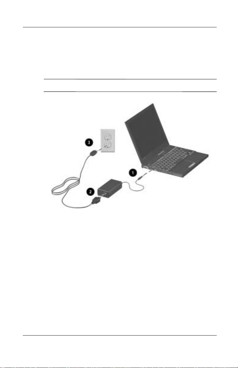
3. Connect the computer to an external outlet.
Plug the AC Adapter cable into the power connector 1. Plug
the power cord into the AC Adapter 2 and into an electrical
outlet 3.
Power cords and electrical outlets vary by country.
✎
Hardware and Software Setup
Hardware Guide 1–3
Page 10
Hardware and Software Setup
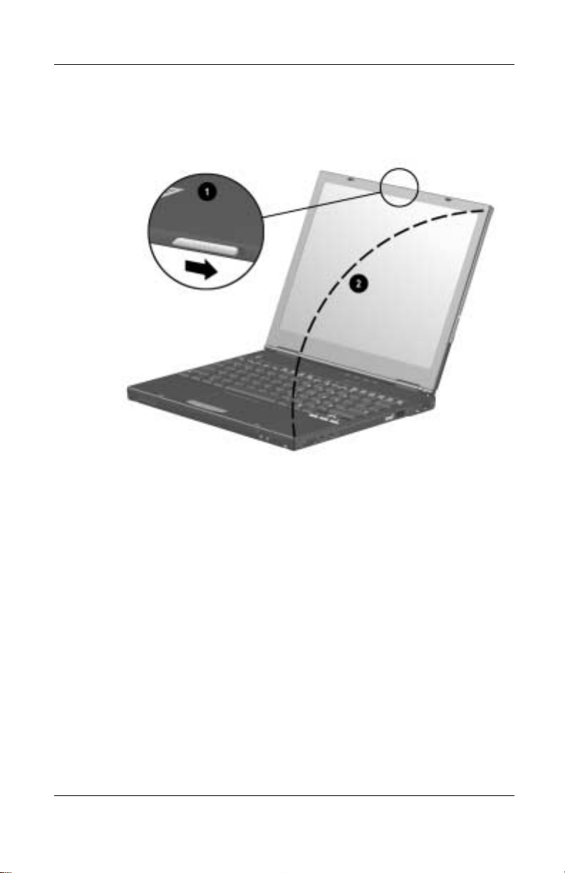
4. Open the computer by sliding the display latch to the right 1
and raising the display 2.
1–4 Hardware Guide
Page 11
Hardware and Software Setup
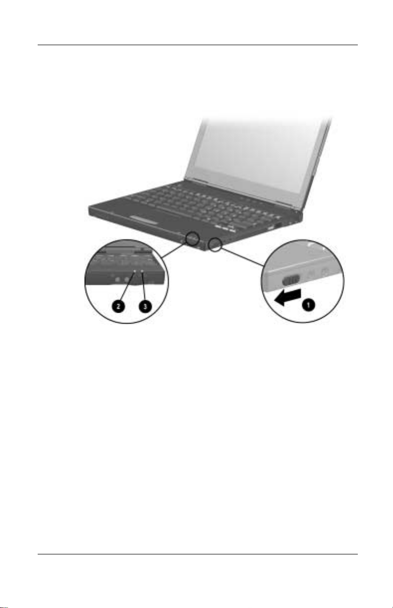
5. Turn on the computer by sliding and momentarily holding,
then releasing, the power switch 1.
When power is turned on:
■ The power/suspend light 2 turns on.
■ The battery pack in the primary battery bay and the external
battery pack (if attached) begin to charge and the battery
light 3 turns on. The battery light:
❏ Rema ins on while the battery packs are charging.
❏ Turns off when the battery packs are fully charged.
■ You are prompted to begin software setup.
Hardware Guide 1–5
Page 12

Hardware and Software Setup
Setting Up the Software
Read the following guidelines, then set up the software:
CAUTION: To prevent file corruption and ensure that the correct drivers
install during initial setup:
Ä
■ Do not unplug the computer f rom the electrical outl et
■ Do not shut down the computer.
■ Do not remove or insert a drive.
■ When you begin software setup, online instructions guide
you through the setup process.
■ After you have begun software setup, you must complete the
entire process. Setup time varies by computer configuration.
■ If you are prompted to select a language or operating system,
choose carefully.
The languages and operating systems that you do not choose will
be deleted from the system and cannot be restored during initial
setup. An operating system available during initial setup is
enhanced by Compaq. When an operating system is deleted, the
enhancements are also deleted.
■ You may be prompted to accept the Product Key.
1–6 Hardware Guide
Page 13

After Software Setup
After the initial setup is complete, you may want to:
■ Install any optional applications.
You can install third-party applications or preloaded Compaq
utilities at any time after initial setup is complete. To install a
third-party application, refer to the documentation included
with the application.
To install a preloaded Compaq utility, select the Setup
Compaq Software icon on the Desktop, then follow the
instructions on the screen.
If the icon does not display on the Desktop after initial setup
is complete, select Start > Run. On the command line, type:
C:\cpqapps\setup.exe preload /s
To view the descriptions and space requirements of preloaded
✎
Compaq utilities without installing the utilities, select the Setup
Compaq Software icon on the Desktop, then select Next. After
viewing the utility information, select Cancel.
Hardware and Software Setup
■ Calibrate the battery pack.
Although you can use a new battery pack that has been fully
charged to run the computer, the computer cannot accurately
report the amount of charge in the battery pack until the
battery pack has been calibrated. For calibration information
and instructions, refer to the “Power Management" section in
the Compaq Utilities guide on the Notebook Products
Reference Library CD included with the computer.
For information about choosing a workspace and creating a safe
and comfortable work environment, refer to the Safety & Comfort
Guide on the Notebook Products Reference Library CD included
with the computer.
Hardware Guide 1–7
Page 14

Hardware and Software Setup
WARNING: To reduce the risk of personal injury, electric shock, fire, or
damage to the equipment:
Å
■ Disconnect power from the equipment by unplugging the power
cord from the electrical outlet.
■ Do not place anything on power cords or cables. Arrange all
cords and cables so no one may accidentally step on or trip
over them.
■ Do not pull on a cord or cable. When unplugging a cord from an
electrical outlet, grasp the cord by the plug.
1–8 Hardware Guide
Page 15
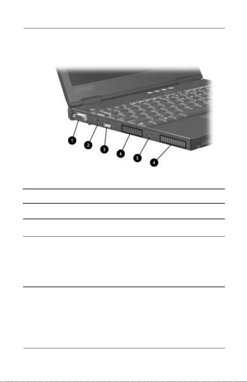
A Look at the Computer
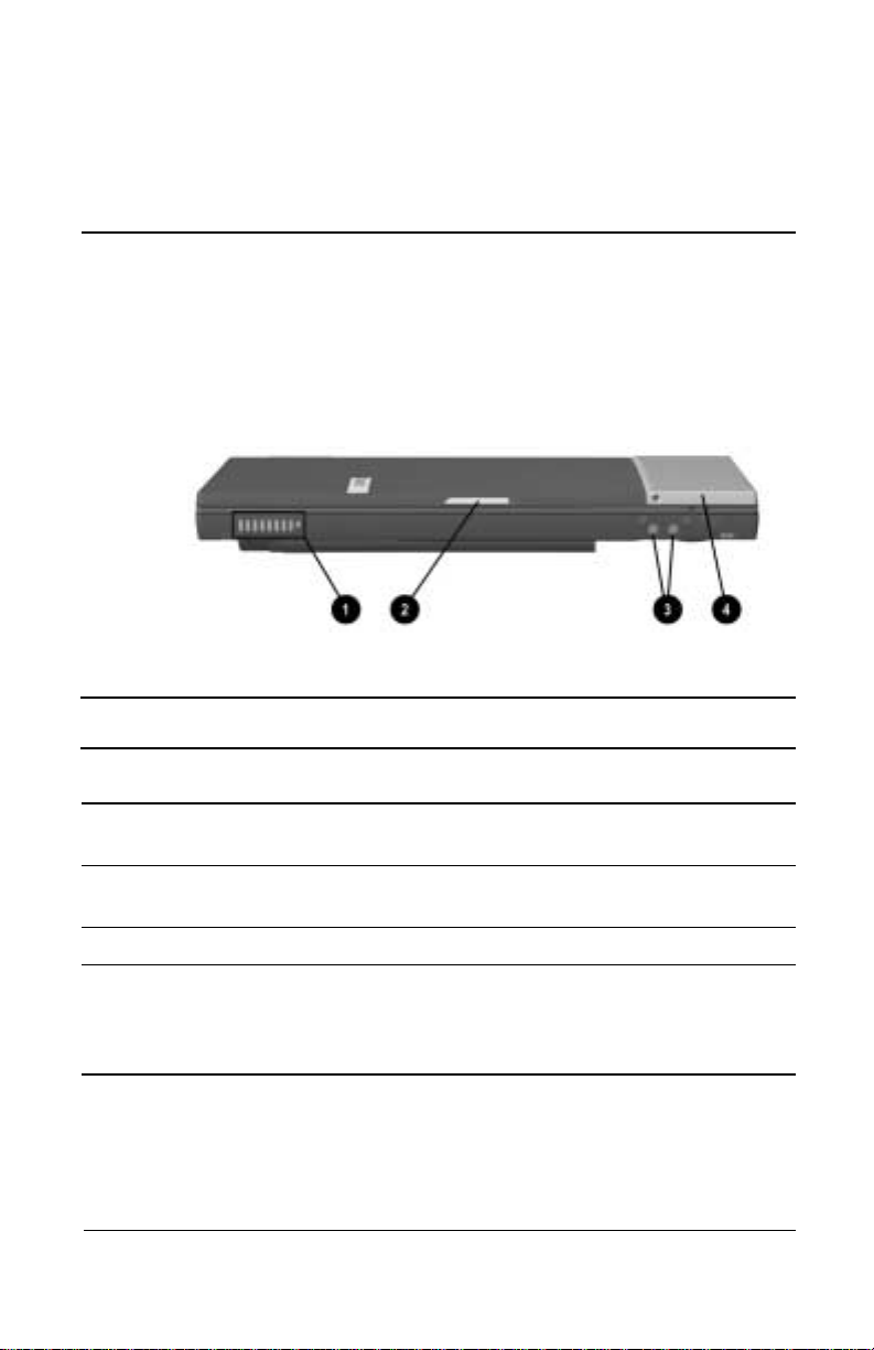
Front Panel Components
Front Panel Components
Display Function
1 Vent s Allow airflow to cool internal
components.
2 Display release latch Releases the display to open the
computer.
2
3 Volume buttons (2) Adjust or mute the system volume.
4 MultiPort Connects wireless communication
devices, such as a Bluetooth or
802.11b MultiPort Module, and
other options.
Hardware Guide 2–1
Page 16
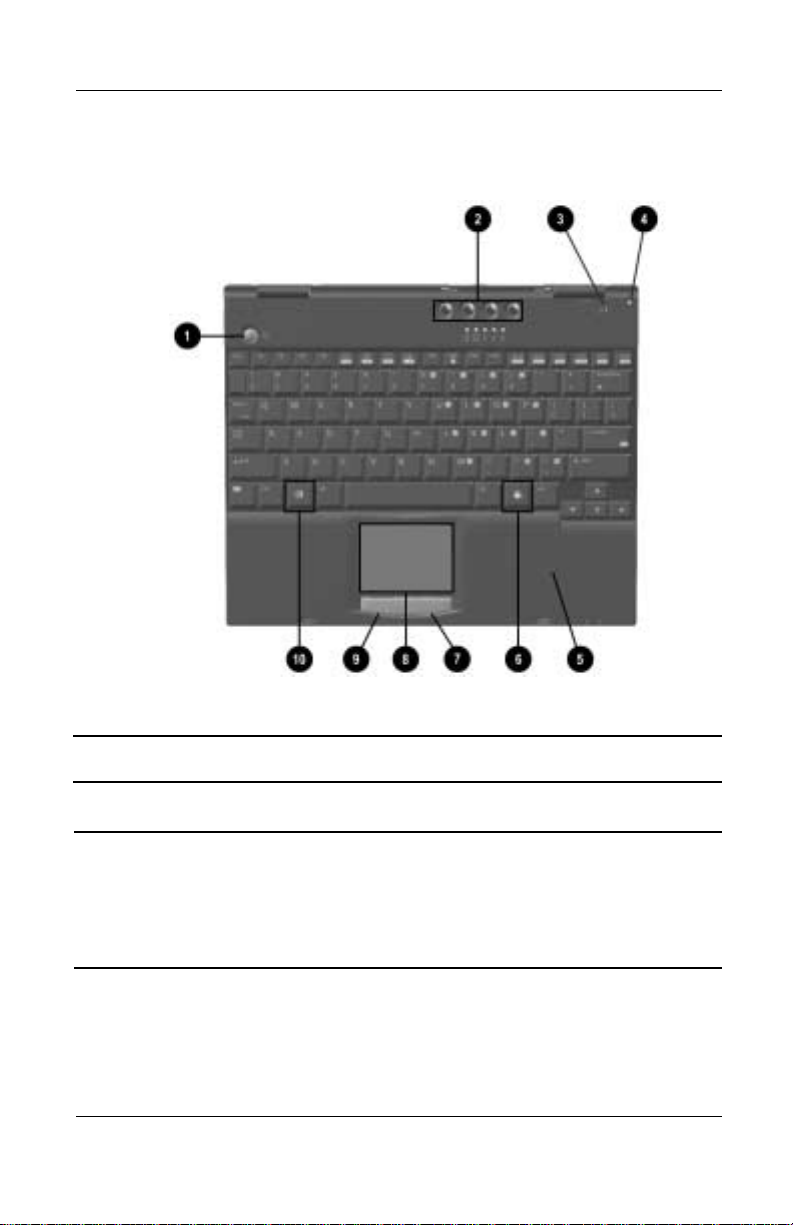
A Look at the Computer
Top Components
Top Components
Light, Button, or Component Function
1 Suspend button*
2–2 Hardware Guide
■ Turns on the computer if it is
off.
■ Initiates and exits Suspend.**
■ When pressed with the Fn
key, initiates Hibernation.
Page 17

A Look at the Computer
Top Components (Continued)
Light, Button, or Component Function
2 Easy Access buttons (4) Four buttons that provide quick
access to the Internet. Refer to
Chapter 3, “Keyboard and Po inting
Devices," for information about
these buttons.
3 Display switch Turns off the computer display if
the computer is closed while on.
4 Microphone Inputs single-channel sound to the
computer; can be used whether
the computer is open or closed.
5 Palm rest Provides To uchPad and T ouchPad
buttons or the pointing stick
buttons. Also protects the internal
hard drive, internal memory
expansion slot, and mode m/NIC
mini PCI slot connector.
6 Windows Application key Displays a menu when using a
Microsoft application. The menu is
the same that is displayed by
pressing the right mouse button.
7 Right TouchPad button
(TouchPad models only)
8 TouchPad
(TouchPad models only)
9 Left TouchPad button
(TouchPad models only)
: Microsoft logo key Displays the Windows St art menu.
* In Windows 98, the term sleep button replaces the term suspend button.
** In Windows 98, the term Standby replaces the term Suspend.
Hardware Guide 2–3
Functions like the right mouse
button on an external mouse.
Moves the mouse cursor, selects,
and activates .
Functions like the left mouse
button on an external mouse.
Page 18
A Look at the Computer
Top Components (continued)
Top Components
Light, Button, or Component Function
1 Pointing stick (pointing stick
models only)
2 Hard drive light On: The primary hard drive is
3 MultiBay light On: A drive in a MultiBay in the
2–4 Hardware Guide
Moves the mouse cursor, selects,
and activates .
being accessed.
optional Mobile Expansion Unit or
an external diskette drive
connected to the computer is
being accessed.
Page 19

A Look at the Computer
Top Components (Continued)
Light, Button, or Component Function
4 Num lock light On: Num lock is on and the
embedded numeric keypad is
enabled.
5 Caps lock light On: Caps lock is on.
6 Scroll lock light On: Scroll lock is on.
7 Left pointing-stick button
(pointing stick models only)
8 Scroll pointing-stick button
(pointing stick models only)
9 Right pointing-stick button
(pointing stick models only)
: Power/suspend light On: Power is turned on.
; Battery light On: A battery pack is charging.
* In Windows 98, the term sleep button replaces the term suspend button.
Functions like the left mouse
button on an external mouse.
Can be set to scroll, magnify, or
function like the third button on an
external mouse.
Functions like the right mouse
button on an external mouse.
Blinking: Computer is in Suspend.*
The power/suspend light
✎
also blinks if a battery
pack that is the only
available power source
reaches a critical
low-battery condition
while Hibernation i s
ydisabled.
Blinking: A battery pack that is the
only available power source has
reached a low-battery condition.
Hardware Guide 2–5
Page 20
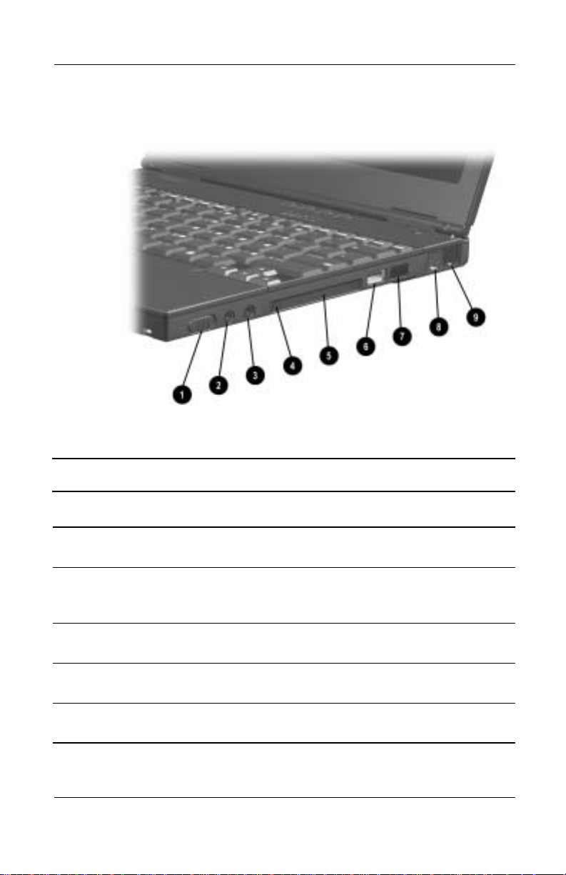
A Look at the Computer
Right Side Components
Right Side Components
Component Function
1 Power switch Turns the computer on or off or
exits Suspend.*
2 Stereo speaker/headphone
jack
3 Microphone jack Connects a single sound channel
4 PC Card eject button Ejects a PC Card from the PC
5 PC Card slot Supports 32-bit (CardBus) and
2–6 Hardware Guide
Connects stereo speakers,
headphones, headset, or
television audio.
microphone.
Card slot.
16-bit PC Cards.
Page 21

Right Side Components (Continued)
Component Function
A Look at the Computer
6 Universal Seria l Bu s (US B)
connector
7 Infrared port Links another IrDA-compliant
8 RJ-45 jack (network models
only)
9 RJ-11 jack (internal modem
models only)
* In Windows 98, the term sleep button replaces the term suspend button.
Connects USB devices.
device for wireless communication.
Connects the network cable.
A network cable is
✎
included with network
models.
Connects the modem cable to an
internal modem.
A modem cable is
✎
included with internal
modem models.
Hardware Guide 2–7
Page 22
A Look at the Computer
Left Side Components
Left Side Components
Component Function
1 External monitor connector Connects an external monitor or
overhead projector.
2 AC power connector Connects any one of the following:
■ AC Adapter
■ Optional Automobile Power
Adapter/Charger
■ Optional Aircraft Power
Adapter
2–8 Hardware Guide
Page 23

Left Side Components (Continued)
Component Function
A Look at the Computer
3 Universal Seria l Bu s (US B)
connector
4 Vent s Allow airflow to cool internal
5 Security cable slot Allows an optional security cable
Connects USB devices.
components.
to be attached to the computer.
Hardware Guide 2–9
Page 24
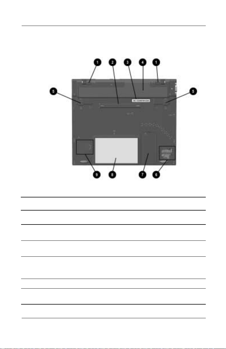
A Look at the Computer
Bottom Components
Bottom Components
Component Function
1 External battery release
latches (2)
2 Docking connector Connects the computer to an
3 Serial number Identifies the computer; needed
4 Battery bay Holds the primary battery pack.
5 Primary battery release
latches (2)
2–10 Hardware Guide
Release the optional external
battery pack.
optional Mobile Expansion Unit.
when you call Compaq customer
support.
Release the primary battery pack
from the primary battery bay.
Page 25

A Look at the Computer
Bottom Components (Continued)
Component Function
6 Fan Provides airflow to cool internal
components.
7 Memory expansion
compartment cover
8 Certificate of Authenticity label Contains the Product Key, which
9 Speaker Produces sound.
Covers the memory expansion
compartment that contains one
memory expansion slot for a
memory expansion board.
may need to be entered before
using some Windows operat ing
systems.
Hardware Guide 2–11
Page 26

A Look at the Computer
Rear Panel Components
Rear Panel Components
Component Function
1 Parallel connector Connects a parallel device.
2 Serial connector Connects a serial device.The
computer serial port is disabled
when the computer is connected
to an optional Mobile Expansion
Unit
3 Composite video-out jack Connects a television, VCR,
camcorder, overhead projector, or
video capture card.
The connection requires
✎
the purchase of a
video-out adapter and an
optional video cable.
2–12 Hardware Guide
Page 27

A Look at the Computer
Additional Standard Components
The components included with the computer vary by geographic
region and the computer hardware configuration ordered.
Hardware Guide 2–13
Page 28

A Look at the Computer
Some components, such as the hard drive and the primary battery
✎
pack, ship inside computer bays identified in previous sections
and are not included in this illustration.
Additional Standard Components
Component Function
1 Power cord Connects the AC Adapter to an AC
electrical outlet.
2 AC Adapter Converts AC power to DC power.
3 3-to-2-prong plug adapter
(Japan only)
Adapts the U.S. power cord to a
two-prong electrical outl et in
Japan.
4 Notebook Products Reference
Library CD
5 QuickRestore kit Contains the software preinstalled
6 Modem cable (internal modem
models only)*
7 Country-specific modem
adapter (included with internal
modem models by region as
required)
Contains the following guides:
■ Hardware Guide
■ Compaq Utilities
■ Modem and Networking
■ Modem Commands
■ Maintenance, Shipping, and
Travel
■ Troubleshooting
■ Regulatory and Safety
Notices
■ Safety & Comfort Guide
on the computer.
Connects the modem to an RJ -11
telephone jack or to a
country-specific adapter.
Adapts the modem cable to a
non–RJ-11 telephone jack.
2–14 Hardware Guide
Page 29

Additional Standard Components (Continued)
Component Function
A Look at the Computer
8 Network cable (network models
only)**
9 Bag containing spare pointing
stick caps (pointing stick
models only)
* The modem cable has a 6-pin RJ-11 connector at each end.
** The network cable ha s an 8-pin RJ-45 connector at each end.
Connects the computer to an
Ethernet network jack.
To replace a worn pointing stick
cap:
1. Turn off the computer.
2. Gently pull off the used rubber
pointing-stick cap.
3. Push the replacement cap into
place.
Hardware Guide 2–15
Page 30

A Look at the Computer
2–16 Hardware Guide
Page 31

Keyboard and Pointing Devices
Using the TouchPad (TouchPad Models)
The T ouchPad performs the same basic operations as a mouse. It
functions with any software that supports a Microsoft-compatible
mouse. The TouchPad
buttons for function or application selection. To operate the
T ouchPad, slide your finger across its surface in the direction you
want to move the cursor, and click t he left or right button to make
a selection or complete an activity.
1 includes left 2 and right 3 TouchPad
3
Hardware Guide 3–1
Page 32

Keyboard and Pointing Devices
Using the Pointing Stick (Pointing Stick Models)
The pointing stick performs the same basic operations as a
mouse. It functions with any software that supports a
Microsoft-compatible mouse.
The pointing stick keyboard includes the pointing stick 1, left
pointing-stick button 2, scroll pointing-stick button 3, and right
pointing-stick button 4. To operate the pointing stick, press on
the pointing stick with your index finger in the direction you want
to move the cursor and click the left or right button to make a
selection or complete an activity. You can also use the pointing
stick to scroll. While pressing on the pointing stick in the
direction you want to scroll, hold down the scroll button.
3–2 Hardware Guide
Page 33

Keyboard and Pointing Devices
Using Hotkeys and Shortcut Keys
Hotkey and Shortcut Key Quick Reference
Function Hotkey Return to Original State
Turn on or off the
wireless device
connected to the
MultiPort
Switch display and
image
Adjust system volume
Initiate Quick Controls
Set power conservation
level
View battery charge
Adjust screen
brightness
Display system
information
Stretch text
Fn Key
Many commands are entered by simultaneously pressing the Fn
key and a function key.
Fn+F2 Fn+F2
Fn+F4 Fn+F4
Fn+F5 Fn+F5
Fn+F6
Enter power-on password
Fn+F7 Fn+F7
Fn+F8 Fn+F8
Fn+F10 Fn+F10
Fn+esc Fn+esc
Fn+T Fn+T
If you enable sequential
entered by simultaneously pressing the
can also be entered by sequentially pressing
T o enable the sequential feature, press the
Fn commands, all commands that can be
Fn key and another key
Fn then the other key.
Fn key 5 times. A beep
following the fifth pressing confirms that the feature is enabled.
The feature remains enabled until you disable it.
Hardware Guide 3–3
Page 34

Keyboard and Pointing Devices
To disable this feature, press the Fn key five times. T o indicate
that the feature has been disabled, rather than enabled, no beep
sounds.
While this feature is enabled:
■ Whenever you press the Fn key, the computer beeps to
indicate that the next key you press will be interpreted as the
other key of an
■ Fn commands can still be entered by simultaneously pressing
Fn key and the other key of the Fn command.
the
Hotkeys
Hotkeys are preset combinations of the Fn key 1 and another key
that access or execute frequently used system functions. The
icons on the function keys
Hotkeys can be used at anytime and from within any application.
Fn command.
F2 to F10 2 represent these functions.
3–4 Hardware Guide
Page 35

Keyboard and Pointing Devices
To use hotkeys on an external keyboard, which does not have an
Fn key, press the scroll lock key twice, then the other key only of
the hotkey combination. For example, to use the
press scroll lock+scroll lock+
The Fn+F6 hotkeys cannot be used on an external keyboard
✎
connected through a USB connector.
F10.
Shortcut Keys
Shortcut keys are preset combinations of the Fn key and another
key other than a function key.
Hotkey and Shortcut Key Procedures
Turning Wireless Devices On or Off (Fn+F2)
When a wireless device is connect to the MultiPort, press Fn+F2 to
turn the device on or off. The status light on the wireless device
indicates whether power is on (light is on) or off (light is off).
Fn+F10 hotkeys,
Switch Display and Image (Fn+F4)
■ Windows 2000 Professional or Windows NT 4.0—Toggle
Fn+F4 to switch the image among:
❏ Computer display
❏ External display
❏ Simultaneous display (computer and external displays)
The external monitor can be connected through the external
monitor connector or the composite video-out jack.
Hardware Guide 3–5
Page 36

Keyboard and Pointing Devices
■ Windows 98 with MultiMonitor Disabled—Toggle Fn+F4
to switch the image among:
❏ Computer display
❏ External display
❏ Simultaneous display (computer and external displays)
The external monitor can be connected through the external
monitor connector or the composite video-out jack.
■ Windows 98 with MultiMonitor enabled—Press Fn+F4 to
turn off an external display connected to the external monitor
connector and disable MultiMonitor.
Adjust System Volume (Fn+F5)
Press Fn+F5 to display the system volume level slide bar. Click
and drag the slide bar upward to increase volume or downward to
decrease volume. Y ou also can adjust the volume with the left and
right arrow keys.
To mute volume, press
Fn+F5+M. To restore volume, press Fn+F5,
then clear the Mute checkbox.
Initiate Quick Controls (Fn+F6)
Quick Controls security features disable the keyboard and
pointing device and clear the display.
Before you can use the Quick Controls, you must set a power-on
password and enable the Quick Control preferences. For
instructions, refer to the Compaq Utilities guide, "Security
Management" section, on this CD.
To initiate Quick Controls manually, press
Controls, enter your power-on password.
The
Fn+F6 hotkeys cannot be used on an external keyboard
connected through a USB connector on the computer or an
optional docking base.
3–6 Hardware Guide
Fn+F6. To exit Quick
Page 37

Keyboard and Pointing Devices
Set Power Conservation Level (Fn+F7)
■ Windows 2000 Professional or Windows 98—Press Fn+F7
to open the Power Schemes window.
■ Windows NT 4.0—Press Fn+F7 to open the Battery
Conservation Settings window.
To select a preset battery conservation level, choose among
■ High—Maximizes running time from a single charge.
■ Medium—Balances system performance with running time.
■ No ne (Drain)—Runs the computer at full power.
For information about the custom level, refer to the Compaq
Utilities guide, "Security Management" section, on this CD.
View Battery Charge (Fn+F8)
Battery pack locations are indicated by number: (1) computer
primary battery bay, (2) computer external battery pack, (3)
Mobile Expansion Unit right MultiBay, and (4) Mobile
Expansion Unit left MultiBay.
Fn+F8 to display the status of all installed battery packs.
Press
Adjust Screen Brightness (Fn+10)
Press Fn+F10 to display the screen brightness control slide bar.
Click and drag upward on the slide bar to increase screen
brightness or downward to decrease screen brightness. You also
can adjust the brightness with the left and right arrow keys.
Display System Information (Fn+esc)
Press Fn+esc to display information about system hardware
components and software version numbers.
Press
Fn+esc a second time to remove the system information
from the screen.
Hardware Guide 3–7
Page 38

Keyboard and Pointing Devices
In some operating systems, the System BIOS date, which may
✎
display in a decimal format, is the version number of the system
ROM.
Stretch Text (Fn+T)
Text stretch expands the text to fill more of the screen. When
MS-DOS is running under Windows and the resolution of the
desktop is set lower than the display resolution, press
stretch the text. Press
normal.
Stretching the text may cause character distortion.
✎
Fn+T to
Fn+T a second time to return the text to
3–8 Hardware Guide
Page 39

Keyboard and Pointing Devices
Using the Embedded Num e ri c Ke y pa d
The embedded numeric keypad consists of a cluster of 16 keys 1.
The character in the upper right corner of each of the keys
indicates the keypad function of that key.
The standard keyboard functions of the keys in the keypad are
disabled when the keypad is enabled.
Enabling the Numeric Keypad
To enable the keypad, press Fn+num lk 2. The Num Lock light 3
turns on when the keypad is enabled.
The keypad cannot be enabled while an optional external
✎
keyboard or numeric keypad is connected to the computer.
Hardware Guide 3–9
Page 40

Keyboard and Pointing Devices
Disabling the Numeric Keypad
To disable the keypad and return the keys to their standard
keyboard functions, press
Fn+Num Lk.
Converting the Numeric Keypad Keys to Standard Keys
To use the keypad keys temporarily as standard keys while the
keypad is enabled:
■ Pre ss and hold Fn to type in lowercase.
■ Pre ss and hold Fn+shift to type in uppercase.
When the
Fn key is released, the keypad function returns.
Enabling the Numeric Keypad at Startup
To set the computer to start up with the keypad enabled:
1. Turn on or restart the computer, then press
F10 = ROM Based Setup message is displayed in the
lower-left corner of the screen.
2. To change the language, press
F2.
3. For navigation instructions, press F1.
4. Select Advanced > Device Options and press enter.
5. Toggle on the Num Lock State at Boot field, then press F10.
6. T o save your selections, select File > Save Changes and Exit,
then press
enter.
7. When prompted to confirm your action, press F10.
To disable the embedded numeric keypad at startup, repeat the
above procedure, toggling off the Num Lock State at Boot field.
F10 when the
3–10 Hardware Guide
Page 41

Keyboard and Pointing Devices
The embedded numeric keypad can be enabled or disabled with
✎
Fn+numlk in either startup state.
Using the Easy Access Buttons
The Easy Access buttons software, preinstalled on the computer,
lets you program the Easy Access buttons on the computer
keyboard to access any Internet addresses or to open any software
application or data file on your hard drive. Each of the four Easy
Access buttons is identified by an icon.
You can use the Easy Access buttons software to:
■ Create and assign button schemes, which are a collection of
button assignments that you define, and that are unique to
your Windows user profile.
■ Change a button name or assignment within a scheme.
■ Delete or add button schemes.
The default assignments for the Easy Access buttons are:
1 Information—Informational Web site
2 Home—Personal Web page
3 Search—Search engine
4 Email—Email application
Hardware Guide 3–11
Page 42

Keyboard and Pointing Devices
For procedures on programming the Easy Access buttons, refer to
the online help file. Select Start > Settings > Control Panel > Easy
Access Keyboard icon. From the Easy Access Buttons window,
select Help.
3–12 Hardware Guide
Page 43

Charging Battery Packs
The computer supports up to two battery packs: a primary battery
pack located in the battery bay, and an optional external battery
pack that can be attached to the computer.
When the computer is attached to an optional Mobile Expansion
Unit (MEU), the system supports up to four battery packs: the
primary and optional external battery packs on the computer and
one battery pack in each of the MultiBays on the MEU.
If the computer and MEU are docked in an optional docking base,
the system supports up to five battery packs: the primary and
optional external battery packs on the computer, one battery pack
in each of the MultiBays on the MEU, and one battery pack in the
MultiBay on the docking base.
Multiple battery packs in the system charge and discharge in a
preset sequence determined by location.
4
Battery Packs
■ Charge sequence:
1—Computer battery bay
2—Optional computer external battery pack
3—Battery pack in the MultiBay of the optional docking base
4—Battery pack in the left MultiBay of the optional Mobile
Expansion Unit
5—Battery pack in the right MultiBay of the optional Mobile
Expansion Unit
Hardware Guide 4–1
Page 44

Battery Packs
■ Discharge sequence:
1—Battery pack in the right MultiBay of the optional Mobile
Expansion Unit
2—Battery pack in the left MultiBay of the optional Mobile
Expansion Unit
3—Optional computer external battery pack
4—Computer battery bay
A battery pack inserted into the MultiBay of the optional docking
✎
base can be charged but cannot be used to provide battery power
to the system.
Using a New Battery Pack
Charge the battery pack in the computer’s battery bay while
connected to an external power source or while attached to the
Mobile Expansion Unit.
A new battery pack should be fully charged before it is used for
the first time. The battery pack will work without being fully
charged, but the battery gauge will not show an accurate charge
until the battery pack receives its first full charge.
4–2 Hardware Guide
Page 45

Replacing a Battery Pack
You can resolve a low battery condition by replacing a discharged
battery pack.
CAUTION: If you are removing a bat tery pack that is t he only power
Ä
source available to the system while the computer is on, initiate
Hibernation before removing the battery pack. Failure to do so will
result in loss of informati on. If th e co m pu ter i s on and connected to
more than one power source, you can remove a battery pack
without initiating Hibernation.
Replacing the Primary Battery Pack
1. If the battery pack in the battery bay is the only power source,
initiate Hibernation.
Drive activity may delay Hibernation.
✎
2. Close the display.
Battery Packs
3. Insert or remove the battery pack:
Hardware Guide 4–3
Page 46

Battery Packs
■ To remove the battery pack, turn the computer bottom side
up.
a. Slide the left primary battery release latch forward 1.
b. Slide the right primary battery release latch forward and
hold it in place 2.
c. Swing the front edge of the primary battery pack up and
back 3.
d. Lift the primary battery pack out of the battery bay 4.
4–4 Hardware Guide
Page 47

Battery Packs
■ To insert the battery pack, turn the computer bottom side up.
a. Slide the left primary battery release latch forward 1
b. Slide the right primary battery release latch forward and
hold it in place 2.
c. Insert the back edge of the battery pack into the battery
bay 3.
d. Swing the front edge of the battery pack forward and
down into the battery bay 4.
e. Rele ase the right primary battery release latch 5
f. Slide the left primary battery release latch toward the
back of the computer 6.
4. Open the display.
5. If the computer is in Hibernation, slide the power switch to
resume operation.
Hardware Guide 4–5
Page 48

Battery Packs
Replacing an Optional External Battery Pack
1. If the optional external battery pack is the only power source,
initiate Hibernation.
Drive activity may delay Hibernation.
✎
2. Close the display.
3. Insert or remove the external battery pack:
■ To remove the optional external battery pack, turn the
computer bottom side up.
4–6 Hardware Guide
Page 49

Battery Packs
a. Make sure the external battery pack is located behind the
computer rear panel, then slide the external battery
release latches toward the inside of the computer 1.
b. Rotate the external battery pack 90 degrees toward the
computer 2.
c. Lift up the battery pack from the computer 3.
Hardware Guide 4–7
Page 50

Battery Packs
■ If the optional external battery pack is being inserted for the
first time, make sure the external battery pack plugs are
removed. T o remove the plugs, turn the computer bottom side
up.
a. Slide the external battery release latches toward the
inside of the computer 1.
b. Remove the plugs from the computer 2.
4–8 Hardware Guide
Page 51

Battery Packs
■ To insert the external battery pack, turn the computer bottom
side up.
a. Slide the external battery release latches toward the
inside of the computer 1.
b. Insert the external battery pack onto the computer until
the contacts connect 2.
c. Rotate the battery pack 90 degrees toward the back of the
computer 3.
d. Slide the external battery release latches toward the
outside of the computer 4.
Hardware Guide 4–9
Page 52

Battery Packs
Storing a Battery Pack
If a computer will be unused and unplugged for more than two
weeks, remove and store the battery pack.
CAUTION: To prevent damage to a battery pack, do not expose it
Ä
to high temperatures for extended periods of time.
To prolong the charge of a stored battery pack, place it in a cool,
dry place. High temperatures cause a battery pack to lose its
charge more quickly, thus reducing battery life.
The recommended storage temperature range is from 32°F to
86°F (0°C to 30°C).
Recycling a Used Battery Pack
To determine if the battery pack program is available in your
geographical region, refer to the Regulatory and Safety Notices
guide on this CD. If your region is not covered, refer to the
Worldwide Telephone Numbers guide included with the computer
and contact your Compaq authorized dealer, reseller, or service
provider.
4–10 Hardware Guide
Page 53

The computer contains a hard drive compartment that supports
only the hard drive and allows you to store and access data.
Caring for Drives
Drives are fragile computer components that must be handled
with care.
CAUTION: To prevent damage to the computer and drive and loss
Ä
of information, ensure that you are discharged of static electricity
before handling a drive. Refer to the Maintenance, Travel and
Shipping guide on this CD for more cautions on handling drives.
Refer to the Regulatory and Safety Notices guide on this CD for
more information on preventing electrostatic discharge damage.
Removing a Hard Drive
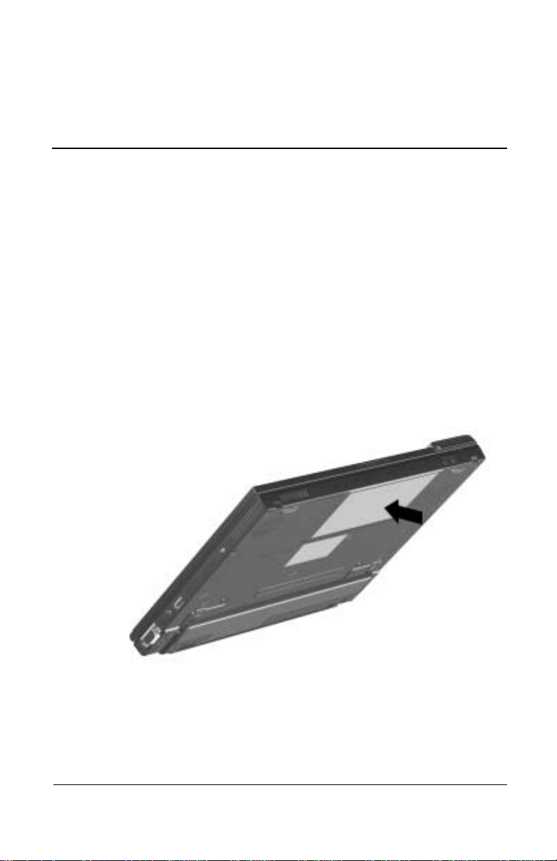
5
Drives
CAUTION: To prevent damage to the computer and hard driv e an d
Ä
loss of information, shut down the computer before removing the
hard drive from the hard drive compartment. Do not remove the
hard drive while the computer is on, in Suspend (Standby), or in
Hibernation. If you are not sure whether the computer is in
Hibernation, turn the computer on, then shut it down. If the
computer is running a retail version of a Windows operating
system, shut down the computer before removing any drive.
1. Save your work.
2. Shut down the computer and close the display.
Hardware Guide 5–1
Page 54

Drives
3. Turn the computer bottom side up.
4. Remove the T8 screws securing the palm rest.
5. Turn the computer top side up with the front facing forward.
6. Open the computer.
5–2 Hardware Guide
Page 55

Drives
7. Slowly lift up the back edge of the palm rest 1 until the RT C
battery 2 and pointing device cables 3 prevent it from lifting
any farther.
Hardware Guide 5–3
Page 56

Drives
8. While holding the palm rest at a 45-degree angle, slide the
front edge of the palm rest away from the base assembly 1.
9. After the front edge of the palm rest clears the base assembly,
swing the front edge of the palm rest up and back 2, and rest
the palm rest on the keyboard 3.
5–4 Hardware Guide
Page 57

Drives
10. Remove the hard drive spacer 1 from the base assembly.
11. Grasp the hard drive tab and slide the hard drive to the left 2.
12. Remove the hard drive 3.
13. Place the removed hard drive in an electrostatic-safe
container.
Hardware Guide 5–5
Page 58

Drives
Inserting a Hard Drive
CAUTION: To prevent damage to the computer and hard driv e an d
Ä
loss of information, shut down the computer before inserting the
hard drive into the hard drive compartment. Do not insert the hard
drive while the computer is on, in Suspend (Standby), or in
Hibernation. If you are not sure whether the computer is in
Hibernation, turn the computer on, then shut it down. If the
computer is running a retail Windows operating system version,
shut down the computer before inse rt in g an y driv e .
1. Shut down the computer and close the display.
2. Place the hard drive in the hard drive compartment, then slide
it into the connector until firmly seated.
3. Replace the hard drive spacer.
4. Replace the palm rest and reinstall the screws.
Changing the Startup Sequence with MultiBoot
The computer can start up from most bootable media or devices.
A bootable medium or device contains files needed by the
computer to start up and operate properly.
When more than one bootable medium or device is in the system,
the computer selects the medium or device to start from by
searching sequenced locations for, first, a bootable CD or DVD
medium; second, a bootable diskette; third, a bootable hard drive,
and fourth, an internal network interface card (NIC).
You can change the sequence in which the computer searches for
a startup medium or device by enabling MultiBoot and entering a
new startup sequence. You can also use MultiBoot Express to set
the computer to prompt you for a startup location each time the
computer is started or restarted.
5–6 Hardware Guide
Page 59

Some devices must be enabled in Computer Setup before they can
be included in a MultiBoot sequence.
Enabling Bootable Media and Devices for MultiBoot
The computer can start by default from the following media and
devices:
■ Any bootable hard drive
■ Any bootable diskette in the external diskette drive
■ Any bootable diskette (but not a SuperDisk LS-120 or ZIP
disk) in an optional docking base
■ Any bootable peripheral interconnect (PCI) NIC in an
optional docking base
The computer can start from the following media and devices
only if the devices are enabled for inclusion in MultiBoot:
■ Any bootable diskette or CD in an optional diskette drive or
CD drive connected by USB to the computer or to an optional
docking base
Drives
■ Any internal NIC
To enable bootable media in USB drives or an internal NIC for
inclusion in MultiBoot:
1. Turn on or restart the computer, then press
F10 while the
F10 = ROM Based Setup message is displayed in the
lower-left corner of the screen.
❏ To change the language, press F2.
❏
For navigation instructions, press F1.
Hardware Guide 5–7
Page 60

Drives
2. Select the Advanced menu > Device Options.
❏ To enable bootable media in USB drives, select Enable
USB legacy support.
❏ To enable an internal NIC, select Internal Network
adapter boot.
3. To save your preferences and exit Device Options, press
4. To close Computer Setup and restart the computer, select
File > Save Changes and Exit, then press
To connect a computer with an internal NIC to a PXE or RPL
✎
server during startup without using MultiBoot (whether or not
MultiBoot or USB legacy support are enabled), press
the Network Service Boot message appears briefly in the
lower-right corner of the screen.
Using the Default Search Sequence
By default, MultiBoot is disabled and the computer selects the
startup medium or device by searching enabled locations in the
following sequence.
The following list describes the order in which drive numbers are
assigned. The actual startup sequence will vary by configuration.
For example, the computer searches only once for a device
containing a medium that can boot as drive A. If the first device it
searches does not contain a medium that can boot as drive A, the
computer begins a single search for a device containing a medium
that can boot as drive C.
F10.
F10.
F12 when
5–8 Hardware Guide
Page 61

Drives
In addition, the availability and location of drive bays in the
system varies by model and configuration, and the availability,
location, and sequencing of PCI slots in a docking base also
varies by model and configuration.
1. CD drive connected by USB that contains a CD that boots as
drive A
2. CD drive in system MultiBay that contains a CD that boots as
drive A
3. Diskette drive connected by USB
4. External diskette drive
5. Diskette drive in system MultiBay
6. Diskette drive in docking base MultiBay
7. SuperDisk LS-120 drive or ZIP drive in system MultiBay
8. CD drive connected by USB that contains a CD that boots as
drive C
9. CD drive in system MultiBay that contains a CD that boots as
drive C
10. Hard drive in computer hard drive compartment
11. Hard drive in system MultiBay
12. Internal NIC in computer
13. Network board in docking base PCI slot
Hardware Guide 5–9
Page 62

Drives
Planning Changes to the Startup Sequence
Before changing the startup sequence, consider the following:
■ When the computer restarts after your changes and searches
for a startup drive, it will consider only the first drive of each
type. For example, in the default boot order, the computer
will not start from a bootable diskette in a docking base if a
non-bootable diskette is in a system MultiBay.
■ Changing the boot order also changes the logical drive
designations. For example, if you start up from a hard drive in
the system MultiBay, that hard drive becomes drive C, and a
hard drive in the hard drive compartment becomes drive D. If
you start up from a diskette drive in an external diskette drive,
that diskette drive becomes drive A. Starting up from a NIC
does not affect logical drive designations.
■ When an external diskette drive is connected to the computer,
the computer searches for a bootable diskette in the external
diskette drive after searching for a bootable diskette in a USB
diskette drive and before searching for a bootable diskette in
any other diskette drive.
Selecting a MultiBoot Utility
You can enable MultiBoot and change the sequence of the startup
media and devices that the computer searches during startup by
using Computer Setup or Compaq Computer Security.
■ Computer Setup can be used even when your operating
system is not working or will not load.
■ Computer Setup includes Express Boot, which can enable
you to choose a startup location each time you start the
computer.
5–10 Hardware Guide
Page 63

■ In Computer Setup, the list of bootable devices includes only
the bootable devices currently in the computer or an optional
docking base. It does not list USB drives or an external
diskette drive.
■ In Compaq Computer Security, the list of bootable devices
includes all bootable devices supported by the BIOS, except
USB drives and an external diskette drive. If you set a startup
sequence for a bootable device that is not currently in the
system, the device will be included in the startup sequence
when it is present and ignored when it not present.
Changing the Startup Sequence in Computer Setup
In Computer Setup, you can set a startup sequence that the
computer uses each time it starts up, or you can use MultiBoot
Express to set the computer to prompt you for a startup location
each time it is started or restarted.
If you set up the MultiBoot Express prompt and do not press a
key or select a startup medium within a time interval you specify,
the computer continues startup according to the current
MultiBoot sequence.
Drives
Setting a Continuing Startup Sequence
To set the computer to start up using the startup sequence you
specify each time it is started or restarted:
1. Restart the computer, then press
Based Setup message is displayed in the lower-left corner of
the screen.
❏ To change the language, press F2.
❏
For navigation instructions, press F1.
2. Select Advanced > Boot Options, then press enter.
3. Toggle the MultiBoot field to Enable.
Hardware Guide 5–11
F10 while the F10 = ROM
Page 64

Drives
4. Toggle the Boot Order fields to the boot sequence you prefer.
5. To save your preferences and exit Boot Options, press
6. To close Computer Setup and restart the computer, select
File > Save Changes and Exit, then press
F10.
Setting the MultiBoot Express Prompt
To set the computer to display the MultiBoot startup location
menu each time it is started or restarted:
1. Restart the computer, then press
Based Setup message is displayed in the lower-left corner of
the screen.
❏ To change the language, press F2.
❏
For navigation instructions, press F1.
2. Select Advanced > Boot Options, then press enter.
3. In the Express Boot Popup Delay (Sec) field, select the
amount of time in seconds that you want the computer to
display the startup location menu before it defaults to the
current MultiBoot setting. (When zero is selected, the
Express Boot startup location menu does not display.)
4. To save your preferences and exit Boot Options, press
F10 while the F10 = ROM
F10.
F10.
5. To close Computer Setup and restart the computer, select
File > Save Changes and Exit, then press
F10.
Responding to the Express Boot Menu
When the Express Boot Menu displays during startup, perform
one of the following steps during the time interval you set when
you enabled MultiBoot Express:
■ To specify a startup location from the Express Boot menu,
select your preference, then press
5–12 Hardware Guide
enter.
Page 65

■ To prevent the computer from defaulting to the current
MultiBoot setting, press any key. The computer will not start
up until you select a startup location, then press
■
To allow the computer to start up according to the current
MultiBoot setting, do not press any key.
Changing the Startup Sequence in Compaq Computer Security
1. Access the Compaq Computer Security window:
❏ Select Start > Settings > Control Panel. Select the
Compaq Computer Security icon.
or
❏ Right-click the Compaq Computer Security icon in the
Windows taskbar, then select Security Properties.
2. Select the Boot Security tab.
3. Select the Enable Multi-Boot checkbox.
Drives
enter.
4. Use the Move Up and Move Down buttons to display your
preference s in the Boot Orde r l ist.
Both buttons are inactive until the Enable MultiBoot box is
selected. The Move Up button is inactive if the selected item
is at the top of the Boot Order List. The Move Down button is
inactive if the selected item is at the bottom of the Boot Order
List.
5. Select the OK button.
Hardware Guide 5–13
Page 66

Drives
5–14 Hardware Guide
Page 67

Using Audio Features
The computer provides the following internal and external audio
features:
6
Audio and Video
Hardware Guide 6–1
Page 68

Audio and Video
Audio Components
Feature Function
1 Speaker Provides audio playback of
multimedia applications. When
using the computer in a Mobile
Expansion Unit (MEU), the speaker
may be disabled and system sou nds
played through the speakers on the
MEU. Consult the documen tation
included with the MEU for additional
information.
2 Volume buttons (2) Adjust or mute the system volume.
3 Stereo speaker/headphone
jack
4 Microphone jack Supports a single sound channel
5 Microphone Supports audio input when the
Connects stereo speakers,
headphones, or a headset to the
computer
(monaural) microphon e with a
3.5-mm plug
display is open and has a standard
sensitivity of -50dB
Connecting a Stereo Speaker/Headphone
When connecting a device to the stereo speaker/headphone jack:
■ Use only a 3.5-mm stereo plug.
■ Use 32-ohm headphones and at least 8-ohm external speakers
for best sound quality.
■ The stereo speaker/headphone jack disables the computer
speaker when an external audio device is plugged into the
jack.
6–2 Hardware Guide
Page 69

WARNING: To reduce the risk of personal injury, turn down the
Å
volume control before putting on headphones.
CAUTION: To prevent possible damage to an external device, do
Ä
not plug a single-sound channel (monaural) connector into the
stereo speaker/headphone jack.
Connecting a Microphone
When connecting a device to the microphone jack:
■ Use a single sound channel (monaural) microphone with a
3.5-mm plug.
■ A powered, single sound channel, electret condenser
microphone is recommended.
■ Only the left channel will be recorded if you use a stereo
microphone.
■ The recommended sensitivity will not be achieved if you use
a dynamic microphone.
Audio and Video
When an external microphone is connected to the computer, the
computer microphone is disabled.
Adjusting Volume
To increase, decrease, or mute the system volume, use the
following methods:
■ Computer volume buttons
❏ To decrease volume, press the left button.
❏ To increase volume, press the right button.
❏ To mute or restore volume, press both buttons
simultaneously.
Hardware Guide 6–3
Page 70

Audio and Video
■ Keyboard Fn+F5 hotkeys
❏ To raise or lower the volume, press Fn+F5, then move the
onscreen slide rule or press the keyboard arrow keys.
❏ To mute or restore volume, press Fn+F5+M or press Fn+F5,
then select or clear the Mute check box.
■ Windows Volume Control window
❏ Double-click the volume icon on the taskbar, then make
your adjustment.
❏ To activate the Windows Volume Control window while
it is open but inactive, press the
Volume can also be adjusted within some applications.
✎
Using Video Features
The composite video-out jack supports any device that accepts
video-in through a composite video connector, such as a
television, VCR, camcorder, overhead projector, or video capture
card.
Fn+F5 hotkeys.
It also supports video signals only. If you are setting up a
configuration that combines audio and video functions, such as
playing a DVD movie to a television, connect the device audio to
the computer’s stereo speaker/headphone jack.
When a composite video device is connected to the video-out
jack, the computer can simultaneously support an image on the
display and on any other supported external displays.
6–4 Hardware Guide
Page 71

Connecting a Device to the Composite Video-Out Jack
You will need:
■ An optional video-out adapter
and
■ A standard composite video cable available from most
television, VCR, or electronics retailers.
To connect a video device to the composite video-out jack:
1. Plug the video-out adapter into the composite video-out jack
on the computer.
2. Connect the composite video cable to the video-out adapter.
3. Connect the composite video cable to the video device as
instructed in the device documentation.
Audio and Video
Hardware Guide 6–5
Page 72

Audio and Video
Changing the Video Mode
Color television standard modes vary even within regions.
✎
However, NTSC is common in North America; PAL, in Europe,
Africa, and the Middle East; NTSC-J, in Japan; and PAL-M, in
Brazil. Other South and Central American regions may use
NTSC, PAL, or PAL-M.
To change the color television standard mode from NTSC
(default):
1. Turn on or restart the computer, then press
F10=ROM Based Setup message is displayed in the
lower-left corner of the screen.
❏ To change the language, press F2.
❏
For navigation instructions, press F1.
2. Select Advanced > Device Options, then press enter.
3. Enter your preference, then press F10.
4. To save your preference, close Computer Setup and restart
the computer, select File > Save Changes and Exit, then press
enter.
5. When prompted to confirm your action, press F10.
F10 while the
6–6 Hardware Guide
Page 73

External Device Connections
External devices can be physically connected to the computer or
to a docking base. In addition, some computer models can
provide connections between infrared-equipped devices or
wireless communication equipment. Refer to the "A Look at the
Computer" section in this guide to locate the connectors on your
computer or to the guide included with your docking base. This
chapter provides procedures for connecting external devices to
the computer.
Connecting an External Monitor
CAUTION: To prevent damage to the computer , turn off th e monitor
Ä
before connecting it to the computer or disconnecting it from the
computer . To prevent damage to the computer display, do not place
an external monitor or any other object on top of the computer
when the computer is close d.
7
To connect an external monitor:
1. Turn off the monitor.
2. Plug the monitor signal cable into the external monitor
connector on the rear panel of the computer.
3. Plug the monitor power cord into a properly grounded
electrical outlet.
4. Turn on the monitor.
Hardware Guide 7–1
Page 74

External Device Connections
5. To ensure that the computer recognizes your monitor type,
refer to the operating system documentation and select the
appropriate manufacturer and model.
If the external monitor does not immediately show an image, try
using the
Fn+F4 hotkeys. Refer to the documentation included
with the monitor for additional setup information.
Connecting a Video Device
Refer to the "Audio and Video" section in this guide for
instructions about connecting a device such as a television, VCR,
camcorder, overhead projector , or video capture card to the
video-out jack.
Connecting a Serial Printer
1. Turn off the printer.
2. Plug the printer end of the printer signal cable into the printer.
3. Connect the serial printer signal cable to the serial connector
on the rear panel of the computer.
4. Plug the printer power cord into a properly grounded
electrical outlet.
5. Turn on the printer.
The Microsoft Windows operating system should prompt you to
set up the printer before printing for the first time. If setup fails,
consult the printer documentation for device driver configuration
information and instructions.
7–2 Hardware Guide
Page 75

External Device Connections
Connecting a Parallel Printer
1. Turn off the printer.
2. Plug the printer end of the printer signal cable into the printer.
3. Connect the signal cable to the parallel connector on the rear
panel of the computer.
4. Plug the printer power cord into a properly grounded
electrical outlet.
5. Turn on the printer.
The Microsoft Windows operating system should prompt you to
set up the printer before printing for the first time. If setup fails,
consult the printer documentation for device driver configuration
information and instructions.
Connecting Infrared Equipment
The infrared port allows communication between the computer
and another infrared-equipped device by producing an invisible
beam of infrared light between the devices. Infrared performance
varies depending on equipment, distance between infrared
devices, and applications being used. The infrared port is
IrDA-compliant and supports both low-speed connections up to
115 kilobits per second (Kbps) and high-speed connections up to
4 megabits per second (Mbps).
Operating system support for infrared communication is currently
available with Windows 98, Windows Me, and Windows 2000
Professional, but not for Windows NT 4.0. To use the infrared
feature on computers running Windows NT 4.0, you need to
purchase optional software.
Hardware Guide 7–3
Page 76

External Device Connections
Infrared Connection Guidelines
■ Be sure the infrared ports on both devices are turned on and
facing each other at a distance no greater than 1.5 feet (about
0.5 meter).
■ Avoid moving the infrared ports away from each other during
data transmission.
■ Avoid interference from remote control units, such as
wireless headphones or audio devices, pointed at the infrared
ports.
■ Avoid direct sunlight, fluorescent light, or flashing
incandescent light close to the infrared ports.
■ Keep the path between the infrared ports free of any objects
that might interfere with data transmission.
7–4 Hardware Guide
Page 77

External Device Connections
■ Do not point one of the ports more than 30 degrees (plus or
minus 15 degrees off the center line) away from the infrared
port of the device you are connecting with.
Infrared Configuration Guidelines
■ The infrared port default settings are as follows:
❏ Port–COM3
❏ Address–3
❏ Interrupt request (IRQ)–3
■ If you use Direct Cable Connection, and the utility prompts
you to choose a port for the infrared connection, you can
select Serial Cable on COM5 or, if the computer is running a
preinstalled Windows 98, Windows Me, or Windows 2000
Professional operating system, select Parallel Cable on LPT3.
Enabling the Infrared Port
The infrared port is enabled by default each time the computer
starts up.
■ When the infrared port is enabled, the infrared icon appears
on the taskbar and Infrared Monitor Search is enabled by
default.
■ While the Infrared Monitor Search is enabled:
❏ You can establish an infrared link.
❏ The system cannot initiate Suspend (Standby).
User-initiated Suspend is not affected.
■ When the Infrared Monitor Search is disabled:
❏ Power is conserved.
❏ You cannot establish an infrared link.
❏ The system can initiate Suspend.
Hardware Guide 7–5
Page 78

External Device Connections
Connecting USB Equi pment
The computer comes equipped with a port that connects
Universal Serial Bus (USB) devices to the computer.
The computer supports certain USB devices without special
drivers. These devices include hubs and keyboards. To connect
USB devices for which the device manufacturer does not provide
special drivers, you need an operating system with USB support,
such as Windows 98 or Windows 2000, preinstalled by Compaq.
A USB keyboard and mouse, optionally connected through a hub,
offer the same functionality as a standard keyboard and mouse
connected through the keyboard, mouse, or single
keyboard/mouse connector.
Attaching a Mobile Expansion Unit
To attach the computer to an optional Mobile Expansion Unit,
refer to the documentation included with the Mobile Expansion
Unit.
Connecting a Docking Base
The computer must be attached to the optional Mobile Expansion
Unit before it can be connected to a docking base. The docking
connector connects the system (computer and Mobile Expansion
Unit) to one of several compatible Compaq docking bases. When
the system is docked, most external devices can be connected to
the docking base, eliminating the need to disconnect external
devices when the system is removed from the workstation. To
connect the computer to a port replicator, Mobile Expansion Unit,
or docking base, refer to the documentation included with the
docking device.
7–6 Hardware Guide
Page 79

Connecting a Modem or NIC
The RJ-11 jack and the RJ-45 jack allow computer models with
an internal modem, internal NIC (network interface card), or both
to connect to a networked interface. You will need to purchase the
modem and network cables if they are not provided with the
computer.
Modem models will need an RJ-11 cable. T o connect the cable:
1. Plug one end of the RJ-11 cable into the RJ-11 jack on the
computer. If the RJ-11 cable contains a noise suppression
circuit, which prevents interference with TV and radio
reception, orient the cable so that the noise suppression
circuitry is closest to the computer.
2. Plug the opposite end of the cable into a standard telephone
wall jack. Or, if applicable, plug the opposite end of the cable
into the phone plug adapter, which then plugs into the wall
jack. Some countries may require an adapter to connect the
modem to the telephone wall jack.
The NIC models will need an RJ-45 cable. To connect the cable:
External Device Connections
1. Plug one end of the RJ-45 cable into the RJ-45 jack on the
computer.
2. Connect the other end of the cable into the network jack.
For information about configuring communication software or
drivers, refer to the Modem and Networking guide.
Connecting to Wireless Devices
The MultiPort allows connection of a wireless device to the
computer. The wireless device provides connection between the
computer and a networked access point. Refer to the
documentation included with the wireless device for hardware
and software installation procedures.
Hardware Guide 7–7
Page 80

External Device Connections
7–8 Hardware Guide
Page 81

8
Computer Upgrades and Add-ons
The computer supports several notebook accessories for you to
upgrade and add on to your system.
To order accessories, visit the Compaq Web site at
http://www.compaq.com, or refer to the Worldwide Telephone
Numbers guide included with your computer to contact a Compaq
authorized dealer, reseller, or service provider.
Before Removing or Installing Components
CAUTION: Electrostatic discharge (ESD) can damage electronic
Ä
components. Before beginni ng any p roced ur e , ensu r e th at yo u are
discharged of static electricity by touching a grounded metal object.
For more information, refer to the Regulatory and Safety Notices
guide.
WARNING: The procedures provided in this section are only for
Å
user-accessible internal compartments on the computer. All other
areas that require a tool to access should only be opened by a
Compaq authorized service provider.
1. Shut down the computer.
To ensure that the computer is not in Hibernation, turn the
✎
computer on, then shut it down.
2. Disconnect all external devices connected to the computer.
Hardware Guide 8–1
Page 82

Computer Upgrades and Add-ons
3. Disconnect the AC Adapter and remove all battery packs
from the computer.
4. Use a T8 screwdriver to remove screws. As you remove
screws from the computer, place them away from the work
area to prevent loss.
Upgrading Memory
Your computer comes with rando m access memory (RAM)
preinstalled in a memory expansion slot under the palm rest. You
can increase the RAM in your computer with optional memory
expansion boards or PC Cards. Memory expansion boards can be
installed in the memory expansion slots on the bottom of your
computer or under the palm rest.
To view the amount of RAM in the system:
■ Windows 98 and Windows Me—Select Start > Settings >
Control Panel > Compaq Diagnostics.
■ Windows NT 4.0 and Windows 2000—Select Start >
Programs > Administrative Tools > Compaq Diagnostics.
When RAM increases, the hard drive space reserved for the
hibernation file also increases. Windows 98 manages this
increase. If the computer is running Windows NT 4.0 or W indows
2000 and you experience problems with Hibernation after
increasing RAM, verify that your hard drive has enough free
space for the larger hibernation file.
8–2 Hardware Guide
Page 83

Computer Upgrades and Add-ons
■ To view the amount of space required by the hibernation file:
❏ Windows 98 and Windows Me—Select Start >
Settings > Control Panel > Power > Hibernation tab.
❏ Windows NT 4.0 and Windows 2000—Select Start >
Settings > Control Panel > Compaq Power > Hibernation
tab.
■ To view the amount of free space on your hard drive, select
My Computer. Right-click your hard drive, then select
Properties.
Removing and Inserting a Memory Expansion Board
WARNING: Failure to unplug the power cord and remove all battery
Å
packs before installing a memory expansion board can damage the
equipment and expo se you to the risk of electrical shock.
Installing a Memory Expansion Board in the
Memory Expansion Compartment
1. Shut down the computer.
2. Close the display.
Hardware Guide 8–3
Page 84

Computer Upgrades and Add-ons
3. Turn the computer bottom side up and remove the screw 1
securing the memory expansion compartment cover to the
base assembly.
4. Lift the back edge of the memory expansion compartment
cover and swing it up and forward 2.
8–4 Hardware Guide
Page 85

Computer Upgrades and Add-ons
5. To add a memory board, insert the memory expansion board
into the empty memory expansion slot at a 45-degree
angle 1, then slide it gently into place until it is seated while
tilted. If a memory board is already installed, remove it. Refer
to “Removing a Memory Board” in this chapter.
All memory expansion boards supported by the computer are
✎
keyed (notched) to ensure correct positioning.
6. Push the memory expansion board down until the plastic
retention clips 2 snap into place.
7. Replace the memory expansion compartment cover and
install the screw.
Hardware Guide 8–5
Page 86

Computer Upgrades and Add-ons
Installing a Memory Expansion Board on the
System Board
1. Shut down the computer.
2. Close the display.
3. Turn the computer bottom side up and remove the four
screws securing the palm rest to the base assembly.
4. Turn the computer top side up.
5. Open the computer.
8–6 Hardware Guide
Page 87

Computer Upgrades and Add-ons
6. Slowly lift up the back edge of the palm rest 1 until the RT C
battery 2 and pointing device cables 3 prevent it from lifting
any farther.
Hardware Guide 8–7
Page 88

Computer Upgrades and Add-ons
7. While holding the palm rest at a 45-degree angle, slide the
front edge of the palm rest away from the base assembly 1.
8. After the front edge of the palm rest clears the base assembly,
swing the front edge of the palm rest up and back 2, and rest
the palm rest on the keyboard 3.
8–8 Hardware Guide
Page 89

Computer Upgrades and Add-ons
9. To add a memory board, insert the memory expansion board
into the empty memory expansion slot at a 45-degree
angle 1, then slide it gently into place until it is seated while
tilted. If a memory board is already installed, remove it. Refer
to “Removing a Memory Board” in this chapter.
All memory expansion boards supported by the computer are
✎
keyed (notched) to ensure correct positioning.
10. Push the memory expansion board down until the plastic
retention clips 2 snap into place.
11. Replace the palm rest reinstall all screws.
Hardware Guide 8–9
Page 90

Computer Upgrades and Add-ons
Removing A Memory Expansion Board
To remove a memory expansion board from the memory slot in
the memory compartment or system board, follow the
instructions to access the memory slot, then:
1. Pull away the plastic retention clips on each side of the
memory expansion board 1. The memory expansion board
tilts upward.
2. Lift the edge of the memory expansion board and slide it
gently out of the memory expansion slot at a 45-degree
angle 2.
3. Place the removed memory expansion board in an
electrostatic-safe container.
8–10 Hardware Guide
Page 91

Computer Upgrades and Add-ons
CAUTION: If memory is not working correctly, try the following:
Ä
■ Reseat the memory module.
■ Memory module may be faulty. Contact the ma nu factur er o f the
memory module.
Upgrading or Adding a Modem or NIC
To remove or install a modem or network interface card (NIC):
1. Turn the computer bottom side up and remove the screws
securing the palm rest.
2. Turn the computer top side up.
3. Open the computer.
Hardware Guide 8–11
Page 92

Computer Upgrades and Add-ons
4. Slowly lift up the back edge of the palm rest 1 until the RT C
battery 2 and pointing device cables 3 prevent it from lifting
any farther.
8–12 Hardware Guide
Page 93

Computer Upgrades and Add-ons
5. While holding the palm rest at a 45-degree angle, slide the
front edge of the palm rest away from the base assembly 1.
6. After the front edge of the palm rest clears the base assembly,
swing the front edge of the palm rest up and back 2, and rest
the palm rest on the keyboard 3.
Hardware Guide 8–13
Page 94

Computer Upgrades and Add-ons
7. If a modem/NIC board is already installed, disconnect the
modem/NIC cable from the board 1.
8. Remove the board by pulling away the plastic retention clips
on each side of the board 2. The board tilts upward.
9. Lift the edge of the board and gently slide it out of the
connector at a 45-degree angle 3.
10. Place the removed board in an electrostatic-safe container.
8–14 Hardware Guide
Page 95

Computer Upgrades and Add-ons
11. To add a new modem/NIC board, align the keyed end of the
board with the keyed area of the modem slot. Carefully insert
the board into the modem slot 1 at a 45-degree angle and
press down on the board 2. When properly seated, the
retainer latches snap into place.
The board connectors are keyed (notched) to ensure correct
✎
positioning.
12. Plug the internal modem-to-RJ11 cable 3 (located inside the
computer) into the connector on the modem/NIC board.
13. Replace the palm rest and reinstall the screws.
14. Connect the modem or network cable to the appropriate jack
on the computer and to the wall. Refer to “Connecting a
Modem or NIC” in Chapter 7.
Hardware Guide 8–15
Page 96

Computer Upgrades and Add-ons
To find additional modem and NIC information, refer to the
following documents:
■ The installation and operation guide included with your new
modem or NIC accessory kit.
■ Mode m and Networking guide, for configuring the modem
and installing software.
■ Modem Commands, for AT Commands, including dial
modifiers and instructions.
Adding and Using PC Cards
A PC Card is a credit card-sized accessory designed to conform
to the standard specifications of the Personal Computer Memory
Card International Association (PCMCIA). The computer
supports both 32-bit CardBus cards and 16-bit PC Cards.
PC Cards are classified as Type I, Type II, or T ype III. The three
types are about the same length and width, but vary in thickness.
Configuring a PC Card
CAUTION: If you install software or enablers provided by a PC Card
manufacturer, you may not be able to use other PC Cards. If you are
Ä
instructed by the documentation that comes with your PC Card to install
device drivers:
■ Install only the device drives for your operating system.
■ Do not install card services, socket services, or enablers.
In Windows 98, Windows Me, and Windows 2000 Professional,
the operating system configures plug-and-play PC Cards.
In Windows NT 4.0 with CardWare provided by Compaq, you
can configure a PC Card in the CardWa re window:
1. Insert the PC Card.
2. Open the CardWare window by selecting Start > Programs >
CardW are.
8–16 Hardware Guide
Page 97

For additional instructions, refer to the Help contents within
CardW are.
Inserting a PC Card
CAUTION: To prevent damage to the connectors, use minimal
Ä
pressure as you insert a PC Card into a PC Card slot.
1. Hold the PC Card label side up with the connector facing the
computer.
2. Gently push the card into the slot until the card is seated.
Computer Upgrades and Add-ons
3. In Windows NT 4.0 with CardWare provided by Compaq,
restart the computer if you are instructed to do so by the PC
Card documentation or an on-screen prompt.
■ If you are inserting a LAN, SCSI, or multifunction PC Card,
you must restart the computer.
■ If you are inserting a modem, ATA, flash, or SRAM PC Card,
it is usually not necessary to restart the computer.
Hardware Guide 8–17
Page 98

Computer Upgrades and Add-ons
Removing a PC Card
CAUTION: Failure to remove a PC Card that extends beyond the
Ä
computer before transporting the computer may cause permanent
damage to the PC Card connectors.
1. Prepare the system for the PC Card removal by completing
one of the following steps:
CAUTION: If the compute r is on and runn ing Windows 98, fa ilure to
Ä
click the command to stop a PC Card before removing it may result
in loss of work or a system lockup.
❏ In Windows 98, Windows Me, and Windows 2000
Professional—If the computer is on, click the command
to stop the PC Card before you remove it. To stop a PC
Card, select the PC Card icon in the taskbar, then select
the PC Card you want to stop, then select Stop Card. A
message displays when the PC Card can be safely
removed.
❏ In Windows NT 4.0 with CardWare provided by
Compaq—If the computer is on, you must shut it down
before removing some PC Cards. Refer to the PC Card
documentation for removal requirements.
Y ou must shut down the computer before removing a LAN, SCSI,
✎
or multifunction PC Card. It is usually not necessary to shut down
the computer before removing a modem, ATA, flash, or SRAM
PC Card.
8–18 Hardware Guide
Page 99

Computer Upgrades and Add-ons
2. Remove the PC Card by following these steps:
a. To release the PC Card eject button, press the button
once 1. To eject the PC Card, press the button a second
time.
b. Gently grasp the card and pull it out 2.
Conserving Energy
When PC Cards are installed in your computer, they draw power
from the system even when they are not in use. To conserve
power:
■ Windows 98 or Windows Me—Select the command to stop
PC Cards or remove PC Cards when they are not in use.
■ Windows NT 4.0 or Windows 2000—Remove PC Cards
when they are not being used.
Hardware Guide 8–19
Page 100

Computer Upgrades and Add-ons
Installing Additional Device Drivers
Device drivers are programs or data files containing information
needed to run a particular PC Card. Most of the device drivers
you need are preinstalled by Compaq.
To save available memory, some device drivers are not turned on.
✎
Some types of PC Cards, such as network cards, Global
Positioning System (GPS) cards, SCSI cards, audio cards, and
multifunction cards, require an additional software device driver
to function properly. The device driver is provided by the PC
Card manufacturer and should be installed according to the
manufacturer’s instructions. Do not install other PC Card
software that is provided by the manufacturer, even if prompted to
do so. The other software may prevent the computer from
working properly with all of your PC Cards.
Attaching the Mobile Expansion Unit
The Mobile Expansion Unit provides storage expansion and
multimedia capabilities with two MultiBays and connectors for
external devices.
T o attach the Mobile Expansion Unit to the computer, refer to the
documentation included with the expansion unit accessory kit.
Docking Bases
When docked in the Mobile Expansion Unit, the computer
supports several Compaq docking bases. Consult an authorized
Compaq dealer for information on bases that will accommodate
your specific expansion needs and work environment. Refer to
the documentation included with the docking base for
information on installing and operating a base with your
computer.
8–20 Hardware Guide
 Loading...