

Page 1
HP Compaq dx6120
Business PC Series - EMEA only
Illustrated Parts Map
Microtower
© 2006 Hewlett-Packard Development Company, L.P.
HP and the HP logo are trademarks of Hewlett-Packard
All other product names mentioned herein may be trademarks of
Development Company, L.P.
their respective companies.
HP shall not be liable for technical or editorial errors or
omissions contained herein. The information in this document is
provided “as is” without warranty of any kind and is subject to
change without notice. The warranties for HP products are set
forth in the express limited warranty statements accompanying
such products. Nothing herein should be construed as
constituting an additional warranty.
3rd Edition, June 2006
1st Edition, January 2005
Document Number
376217-003
Standard and Optional Boards
1
System board with alcohol pad and thermal grease 419303-001
Memory Modules
* 256 MB/533 MHz FSB, DDR2, PC2-4200
* 512 MB/533 MHz FSB, DDR2, PC2-4200
Intel Celeron D Processors with thermal grease and alcohol pad
* 2.8 GHz/533 MHz FSB, 256 KB cache 391941-001
* 3.06 GHz/533 MHz FSB, 256 KB cache 405693-001
* 3.2 GHz/533 MHz FSB, 256 KB cache 382503-001
Intel Pentium 4 Processors with thermal grease and alcohol pad
* 2.8 GHz/800 MHz FSB, 1 MB cache 394643-001
* 3.0 GHz/800 MHz FSB, 2 MB cache 419651-001
* 3.06 GHz/533 MHz FSB, 1 MB cache 412985-001
* 3.2 GHz/800 MHz FSB, 2 MB cache 384786-005
* 3.4 GHz/800 MHz FSB, 2 MB cache 384787-005
Other Cards
* PCI Modem, ATX 398661-001
* Intel Gigabit NIC
Graphics Solution
* ATI RV515 VGA graphics, 256M, ATX bracket 413023-001
FH = Full Height mounting bracket
* Not shown
393392-001
393393-001
398332-001
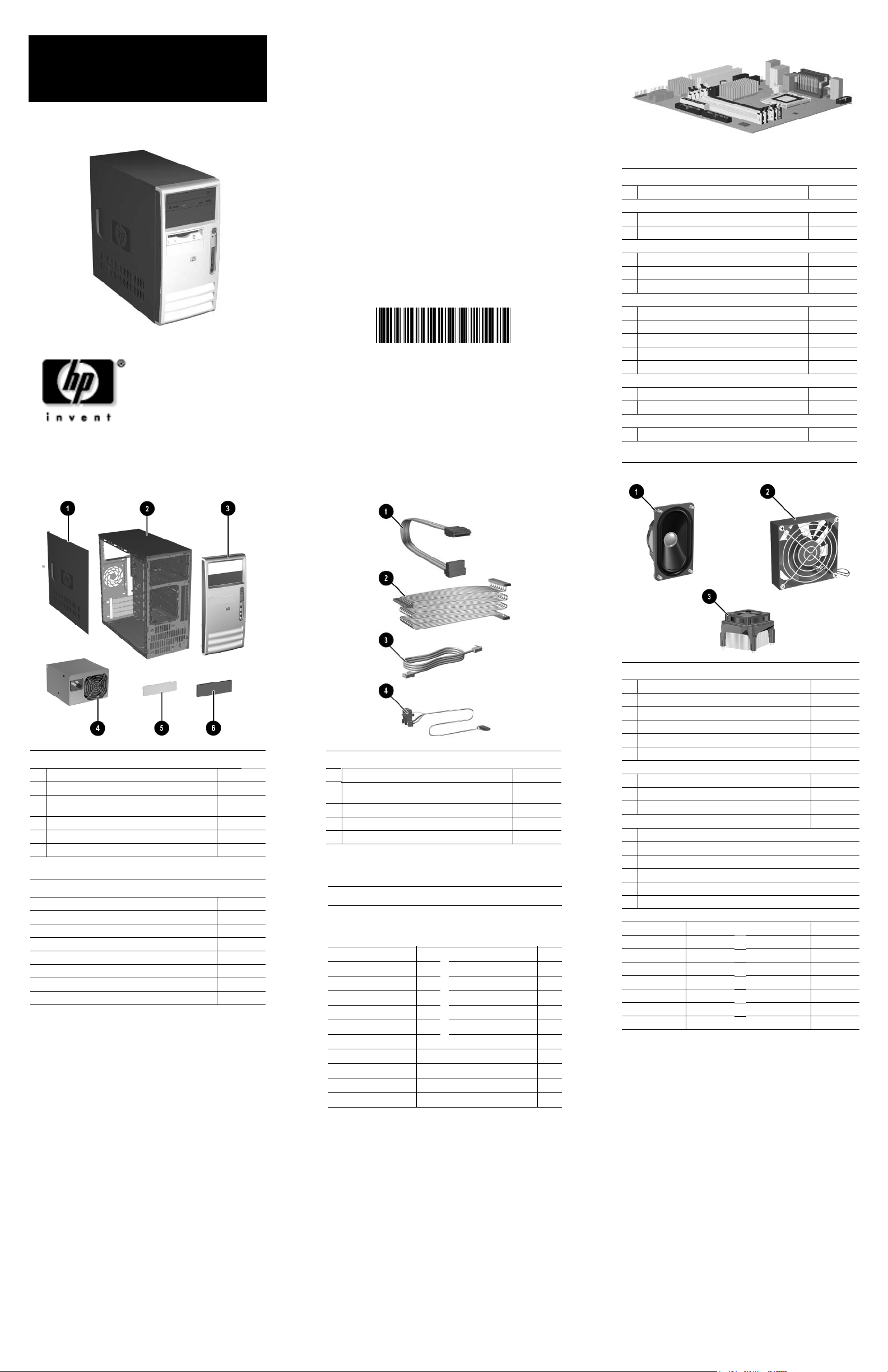
System Unit
1 Access panel 395969-001
2 Chassis not spared
3 Front bezel with 5.25” ODD bezel blank and lower
3.5” bezel blank, painted
4 Power supply, PFC, 300W, ATX 405872-001
5 3.5” bezel blank, top bay, painted 335938-005
6 5.25” bezel blank, carbonite 335937-005
Mass Storage Devices (not illustrated)
40 GB\7200 RPM SATA hard drive 365555-001
80 GB\7200 RPM SATA hard drive 345713-005
160 GB\7200 RPM SATA hard drive 345712-005
250GB\7200 RPM SATA hard drive 393303-001
48X CD-ROM drive with mounting screws 397130-001
48X/32X/48X +16X DVD/CD-RW drive 405425-001
16X DVD+R/RW drive 405760-001
16/48X DVD ROM drive 405761-001
368085-001
Cables
1 SATA hard drive cable, 13-inch 391738-001
2 IDE UATA dual device, Optical Disk Drive data
cable, 14-inch
3 RJ-11 telephone cable 198220-005
4 Power/LED cable with switch and switch holder 395965-001
* USB+audio front I/O panel cable 395966-001
*Not shown
Keyboard (not illustrated)
PS/2, Basic
USB, Basic
PS/2, Basic[1]
USB, Basic[1]
Belgian -181
BHCSY -B41 Italian -061
Czech -221 Norwegian -091
Danish -081
Finnish -351 Romanian -271
French -051
French Arabic -DE1 Spanish -071
German -041 Swedish -101
Greek[1] -151 Swiss -111
Hebrew -BB1
Hungarian -211 U.K. -031
[1] 396215, 396217 - Greek (-151) only
382925-xxx
382926-xxx
396215-xxx
396217-xxx
International -B31
Portuguese -131
Slovakian -231
Turkish -141
395964-001
Miscellaneous Parts
1 Speaker 399871-001
2 Chassis fan 392412-001
3 Heatsink with fan, alcohol pad, and thermal grease 418841-001
* Real-time clock battery 153099-001
* Rubber foot (4 ea) 370708-001
* Media card reader, 3.5-inch 407187-001
Mouse
* 2-Button, PS/2, with scroll wheel 390937-001
* 2-Button, USB, optical with scroll wheel 390938-001
* 2-Button, PS/2, optical with scroll wheel 417966-001
Miscellaneous screw kit, includes: 414180-001
* M3 x 5mm hi top, taptite, (4 ea) (247348-001)
* #6-32 x 1/4 Hi top, taptite, T15 (4 ea) (192308-001)
* #6-32 x 5/16 Hi top, taptite, T15 (2 ea) (192308-002)
* #6-32 x 3/16 Hi top, taptite, T15 (4 ea) (192308-003)
* Countersunk, flat head plastite (4 ea) (247481-001)
* Thumbscrew (1 ea) (368224-002)
Modem Cable Adapters (not illustrated) (use with 198220-005)
Belgium 316904-181 Italy 316904-065
Cameroon 316904-AR1 Macedonia 419652-001
Czech 234963-225 Netherlands 316920-335
Germany 316904-045 Poland/Russia 316904-241
Greece 316904-151 Scandinavia 382848-DH1
France 316904-051 Switzerland 304398-115
Hungary 234963-215 Turkey 316904-141
Israel 316904-BB1 U.K. 158593-035
*Not shown
Page 2
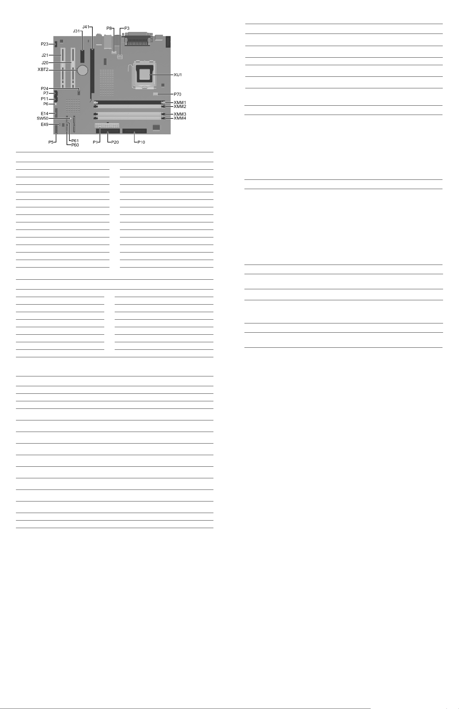
System Board Connectors and Jumpers (position of some untitled components may vary in location)
E49 Password jumper P20 Primary IDE
J20 PCI slot 1 P23 Front audio/USB
J21 PCI slot 2 P24 Front USB header
J31 PCI Express x1 P60 Primary Serial ATA (SATA) connector
J41 PCI Express x16 P61 Second Serial ATA (SATA) connector
P1 Main power (20 pin) P70 CPU fan
P3 VCCP 12 volt header SW50 CMOS button
P5 Front power button, LED header XBT2 Battery
P6 Internal chassis speaker XMM1 Memory socket
P7 CD audio in XMM2 Memory socket
P8 Chassis fan XMM3 Memory socket
P10 Diskette drive XMM4 Memory socket
P11 Aux audio in XU1 Processor socket
E14 Boot Block
System Hardware Interrupts
IRQ System Function IRQ System Function
0 Timer Interrupt 8 Real-Time Clock
1 Keyboard 9 Unused
2 Interrupt Controller Cascade 10 Unused, available for PCI
3 Serial Port (COM B) 11 Unused, available for PCI
4 Serial Port (COM A) 12 Mouse
5 Unused, available for PCI 13 Coprocessor
6 Diskette Drive 14 Primary ATA (IDE) Controller
7 Parallel Port (LPT 1)
Keyboard Light Combinations Used by Boot Block ROM
Failsafe Boot
Block ROM
Num, Caps,
Scroll Lock
Caps Lock Green On Enter password.
Num, Caps,
Scroll Lock
Num, Caps,
Scroll Lock
* Diagnostic lights do not flash on USB keyboards
Clearing CMOS
The computer's configuration (CMOS) may occasionally be corrupted. If it is, it is necessary to clear the CMOS
memory using switch SW50.
To clear and reset the configuration, perform the following procedure:
1. Prepare the computer for disassembly.
Ä
2. Remove the access panel.
3. Press the CMOS button located on the system board and keep it depressed for 5 seconds.
4. Replace the access panel.
5. Turn the computer on and run F10 Computer Setup (Setup utility) to reconfigure the system. You will receive POST
error messages after clearing CMOS and rebooting advising you that configuration changes have occurred.
Disabling or Clearing the Power-On and Setup Passwords
1. Turn off the computer and any external devices, and disconnect the power cord from the power outlet.
2. With the power cord disconnected, press the power button again to drain the system of any residual power.
3. Remove the access panel.
4. Locate the header and jumper labeled E49.
5. Remove the jumper from pins 1 and 2. Place the jumper over pin 2 only to avoid losing it.
6. Replace the access panel.
7. Plug in the computer and turn on power. Allow the operating system to start.
NOTE: Placing the jumper on pin 2 clears the current passwords and disables the password features.
8. To re-enable the password features, repeat steps 1-4, then replace the jumper on pins 1 and 2.
9. Repeat steps 6-7, then establish new passwords.
Refer to the Computer Setup (F10 Setup) instructions to establish new passwords.
Computer Setup (F10) Utility Features (features may vary)
File
Storage
Security
Power
Advanced
Keyboard LED
Color
Green On ROMPaq diskette not present, is bad, or drive
Green Blink On in sequence, one at a
Green On Boot Block ROM Flash successful. Turn power
CAUTION: The power cord must be disconnected from the power source before pushing the Clear CMOS
Button (NOTE: All LEDs on the board should be OFF). Failure to do so may damage the system board.
System Information
About
Set Time and Date
Device Configuration
Storage Options
Setup Password
Power-On Password
Password Options
Smart Cover
Embedded Security
OS Power Management Hardware Power Management Thermal
Power-On Options
BIOS Power On
Onboard Devices
LED Activity State/Message
not ready.*
time - N, C, SL
Replicated Setup
Default Setup
Apply Defaults and Exit
DPS Self-Test
Boot Order
Drivelock Security
Data Execution Prevention
Master Boot Record Security
Save Master Boot Record
Restore Master Boot Record
PCI Devices
Bus Options
Keyboard locked in network mode.
off, then on to reboot.
Ignore Changes and Exit
Save Changes and Exit
Device Security
Network Service Boot
System IDs
Device Options
PCI VGA Configuration
Computer Diagnostic LEDs (on front of computer)
LED Color LED/Beep Activity State/Message
Power Green On (S0) Computer on
Power Green 1 blink every 2 seconds (S1) Suspend Mode
Power Red* 2 blinks and beeps 1 second
Power Red* 3 blinks and beeps 1 second
Power Red* 4 blinks and beeps 1 second
Power Red* 5 blinks and beeps 1 second
Power Red* 6 blinks and beeps 1 second
Power Red* 7 blinks and beeps 1 second
Power Red* 8 blinks and beeps 1 second
Power Red* 9 blinks and beeps 1 second
Power Red* 10 blinks and beeps 1 second
Power None None System unable to power on.
Hard Drive Green Blinking Hard drive activity
*Beeps will occur only for 5 iterations and then stop. LEDs will continue to blink until corrective action is taken.
apart
apart
apart
apart
apart
apart
apart
apart
apart
CPU thermal shutdown
CPU not installed
Power supply failure
Pre-video memory error
Pre-video graphics adapter error
System board failure
Invalid ROM checksum
Wrong power supply input voltage
Bad option card
 Loading...