


HP Cluster Platform
Part Number: 614066-002
ProLiant G6 and G7 Server Overview
Abstract
This document provides an overview of the core infrastructure components for all HP Cluster Platform models and associated platforms for
experienced hardware administrators of large-scale computer systems and for HP Global Service representatives. This guide refers to the original
component documentation, which should be available during installation, configuration, and maintenance operations.
February 2011
Edition: 2

© Copyright 2010, 2011 Hewlett-Packard Development Company, L.P.
The information contained herein is subject to change without notice. The only warranties for HP products and services are set forth in the express
warranty statements accompanying such products and services. Nothing herein should be construed as constituting an additional warranty. HP shall
not be liable for technical or editorial errors or omissions contained herein.
Intel and Xeon are trademarks or registered trademarks of Intel Corporation or its subsidiaries in the United States and other countries.
AMD is a trademark of Advanced Micro Devices, Inc.

Contents
Introduction .................................................................................................................................. 5
Overview ................................................................................................................................................. 5
HP ProLiant servers (rack) ............................................................................................................... 6
HP ProLiant Rack Servers (Intel® Xeon®) ...................................................................................................... 6
HP ProLiant DL160 G6 Server ........................................................................................................... 6
HP ProLiant DL1000 Multi Node Servers ............................................................................................. 9
HP ProLiant DL2000 Multi Node Servers ........................................................................................... 12
HP ProLiant DL380 G6 Server ......................................................................................................... 18
HP ProLiant DL380 G7 Server ......................................................................................................... 23
HP ProLiant Rack Servers (AMD Opteron) ................................................................................................... 27
HP ProLiant DL165 G6 Server ......................................................................................................... 27
HP ProLiant DL165 G7 Server ......................................................................................................... 31
HP ProLiant DL385 G6 Server ......................................................................................................... 35
HP ProLiant DL385 G7 Server ......................................................................................................... 39
HP ProLiant DL585 G6 Server ......................................................................................................... 42
HP ProLiant servers (scalable) ....................................................................................................... 47
HP ProLiant SL6000 G6 Servers ................................................................................................................ 47
HP ProLiant SL6500 G6 Servers ................................................................................................................ 47
HP ProLiant Scalable Servers (Intel® Xeon®) ............................................................................................... 47
HP ProLiant SL170s G6 Server ........................................................................................................ 47
HP ProLiant SL2x170z G6 Server .................................................................................................... 52
HP ProLiant SL390s G7 Server ........................................................................................................ 54
HP ProLiant Scalable Servers (AMD Opteron) .............................................................................................. 60
HP ProLiant SL165z G7 Server ........................................................................................................ 60
HP ProLiant BL c-Class Server Blades ............................................................................................. 63
HP BladeSystem c7000 Enclosure ............................................................................................................. 63
HP BladeSystem c7000 Enclosure documentation .............................................................................. 63
Enclosure front components ............................................................................................................. 64
Enclosure rear components ............................................................................................................. 65
Device bay numbering ................................................................................................................... 65
Interconnect module bay numbering ................................................................................................. 67
Port mapping: HP BladeSystem c7000 Enclosure interconnect module bay to server blade ..................... 67
Server blade type to gigabit Ethernet blade switch bandwidth ratios .................................................... 68
HP BladeSystem c-Class Switch Modules........................................................................................... 68
Mezzanine HCA cards ................................................................................................................... 70
HP ProLiant BL c-Class Server Blades (Intel® Xeon®) .................................................................................... 70
HP ProLiant BL280c G6 Server Blade ............................................................................................... 70
HP ProLiant BL2x220c G6 Server Blade ........................................................................................... 73
HP ProLiant BL2x220c G7 Server Blade ........................................................................................... 75
HP ProLiant BL460c G6 Server Blade ............................................................................................... 76
HP ProLiant BL460c G7 Server Blade ............................................................................................... 79
HP ProLiant BL c-Class Server Blades (AMD Opteron) ................................................................................... 81
HP ProLiant BL465c G6 Server Blade ............................................................................................... 81
HP ProLiant BL465c G7 Server Blade ............................................................................................... 83
Contents 3

Support and other resources ........................................................................................................ 85
Technical support .................................................................................................................................... 85
Contacting HP ............................................................................................................................... 85
Documentation feedback .......................................................................................................................... 85
Related documentation ............................................................................................................................. 86
Cluster component documentation ................................................................................................... 86
HP Cluster Platform documentation ................................................................................................... 86
Bracket installation guides .............................................................................................................. 87
Important safety information ...................................................................................................................... 87
Typographic conventions .......................................................................................................................... 87
Acronyms and abbreviations ........................................................................................................ 89
Index ......................................................................................................................................... 91
Contents 4
Introduction
Overview
This document provides an overview of the HP ProLiant G6 and G7 servers used in HP Cluster Platform
solutions. This document refers to the original component documentation for detailed information, except
where information or procedures for the cluster differ from the standalone components. In such cases, this
document supersedes information supplied in existing component documentation.
Some server options are not supported in HP Cluster Platform configurations. For more information, contact
an HP representative.
Processor Supported server
Intel® Xeon®
AMD Opteron
HP ProLiant DL160 G6 Server
HP ProLiant DL170e G6 Server
HP ProLiant DL170h G6 Server
HP ProLiant DL380 G6 Server
HP ProLiant DL380 G7 Server
HP ProLiant SL170s G6 Server
HP ProLiant SL2x170z G6 Server
HP ProLiant SL390s G7 Server
HP ProLiant BL280c G6 Server Blade
HP ProLiant BL2x220c G6 Server Blade
HP ProLiant BL2x220c G7 Server Blade
HP ProLiant BL460c G6 Server Blade
HP ProLiant BL460c G7 Server Blade
HP ProLiant DL165 G6 Server
HP ProLiant DL165 G7 Server
HP ProLiant DL385 G6 Server
HP ProLiant DL385 G7 Server
HP ProLiant DL585 G6 Server
HP ProLiant SL165z G7 Server
HP ProLiant BL465c G6 Server Blade
HP ProLiant BL465c G7 Server Blade
This document does not include the procedures or tools required to install and configure the system hardware
or software. It includes references for cluster components and pointers to the server documentation on the HP
website.
Introduction 5
HP ProLiant servers (rack)
HP ProLiant Rack Servers (Intel® Xeon®)
Several Intel® Xeon® servers are supported in HP Cluster Platform solutions. This section presents information
for the HP ProLiant servers that are used in HP Cluster Platform solutions only. The content in this section
includes the following additional information for the ProLiant Intel® Xeon® servers:
• Front and rear views
• InfiniBand HCA PCI slot assignment
• Specific cable management instructions, if necessary
• HP Cluster Platform specific maintenance instructions, if applicable
HP ProLiant DL160 G6 Server
The HP ProLiant DL160 G6 Server is used as a control node, a utility node, and a compute node in HP Cluster
HP ProLiant DL160 G6 Server documentation
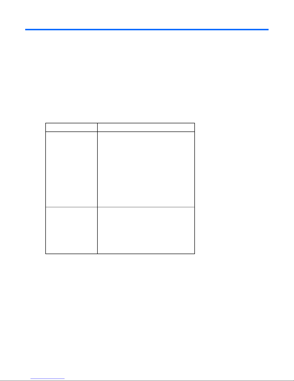
Front panel components (DL160 G6)
Platform configurations.
For server-specific information, see the server documentation:
• For a complete list of features and specifications, see the HP ProLiant DL160 Generation 6 (G6)
QuickSpecs on the HP website
(http://h18004.www1.hp.com/products/quickspecs/13247_na/13247_na.html).
• For installation and service information, see the HP ProLiant DL100 Series Server User Guide and the HP
ProLiant DL160 G6 Server Maintenance and Service Guide on the HP website
(http://www.hp.com/support/manuals).
Under servers, select ProLiant ML/DL and TC series servers, and then select HP ProLiant DL160 G6
Server series.
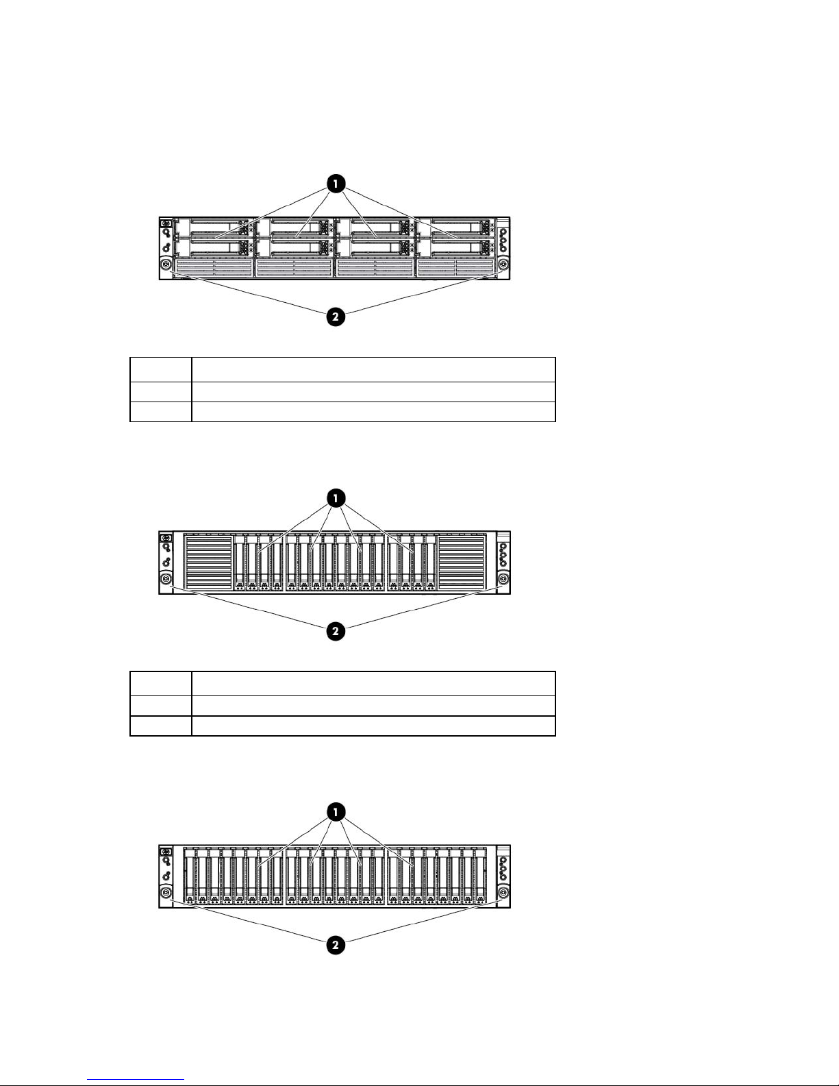
This figure shows the LFF hard drive model. The server is also available in a two-drive LFF model, a four-drive
non-hot plug LFF model, and an 8-drive SFF model. Each model contains the same components in the same
or similar orientations.
HP ProLiant servers (rack) 6
Item Description
1
2
3
4
5
Optical drive (optional)
Serial label pull tab
USB connectors (2)
Rack mounting thumbscrews (2)
Hard drive bays (4)
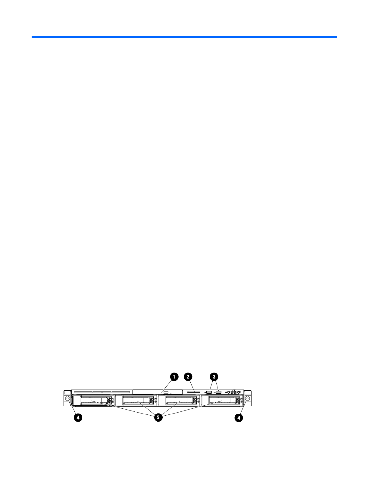
Front panel LEDs and buttons (DL160 G6)
This figure shows the LFF hard drive model. The server is also available in a two-drive LFF model, a four-drive
non-hot-plug LFF model, and an 8-drive SFF model. Each model contains the same components in the same
or similar orientations.
Item Description Status
1
2
3
4
5
6
7
Optical drive LED Flashing green = Drive is in use.
Off = Drive is not active.
Health LED Green = System health is normal.
Amber = System health is degraded (non-critical).
Red = System health is critical.
Off = System health is normal (when in standby mode).
NIC 1 activity LED Green = Network link exists.
Flashing green = Network link and activity exist.
Off = No network link exists.
NIC 2 activity LED Green = Network link exists.
Flashing green = Network link and activity exist.
Off = No network link exists.
Hard drive activity LED Flashing green = Drive activity exists.
Off = No drive activity exists.
Power button/LED Green = Normal (system on)
Amber = System is in standby, but power is still applied.
Off = Power cord is not attached, or the power supply has failed.
There is no power to the system.
UID button/LED Blue = Identification is activated.
Flashing blue = System is being managed remotely.
Off = Identification is deactivated.
HP ProLiant servers (rack) 7
Item Description Status
Power supply cable connector
NIC 2 connector
T-10/T-15 Torx screwdriver
8
Drive online/error LED Blue = Drive identified
Amber = Drive failure
Off = No fault-process activity
9
Drive activity LED Flashing green = Drive activity
Off = No drive activity
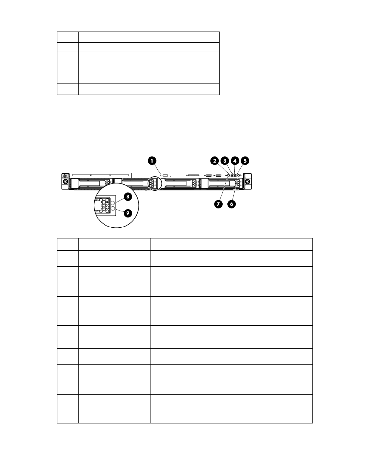
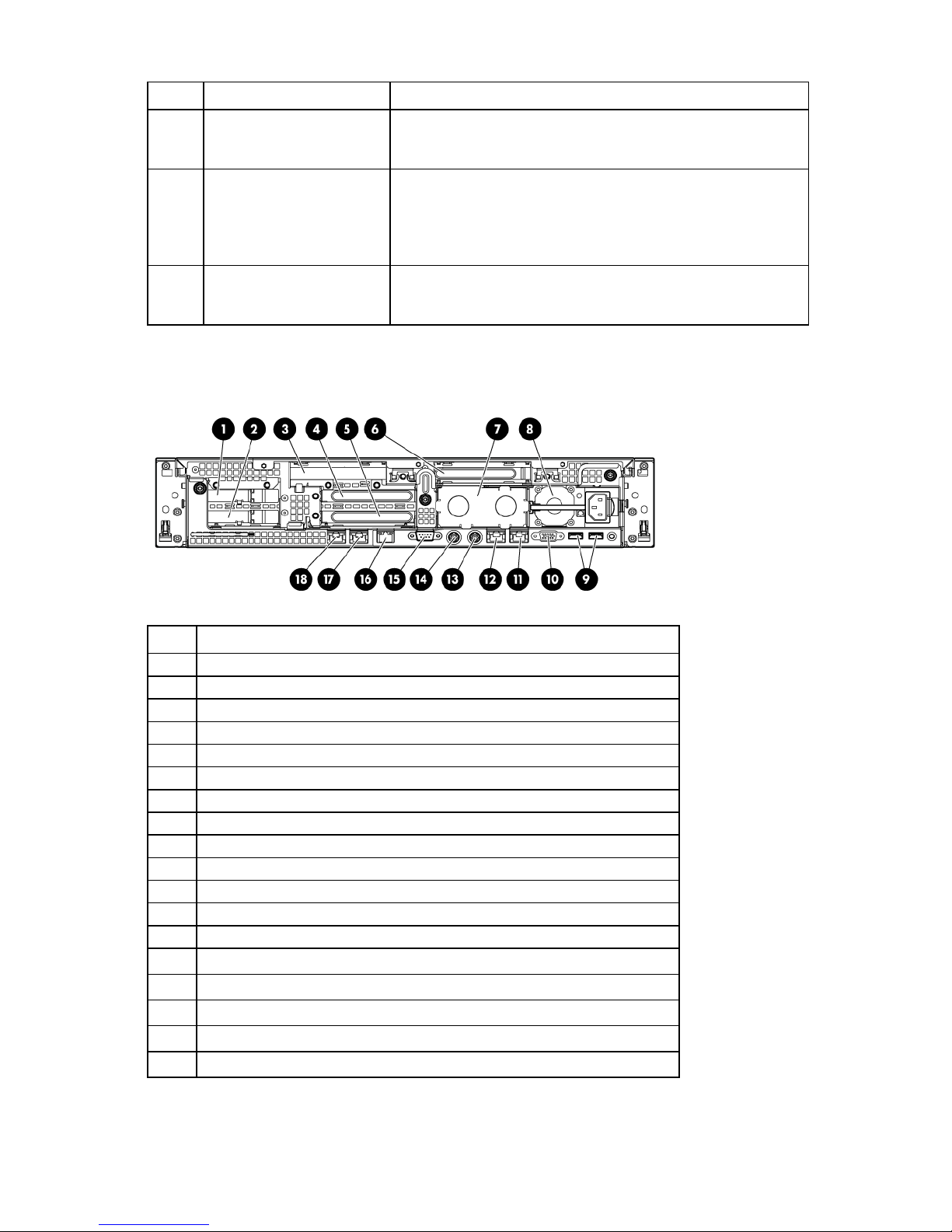
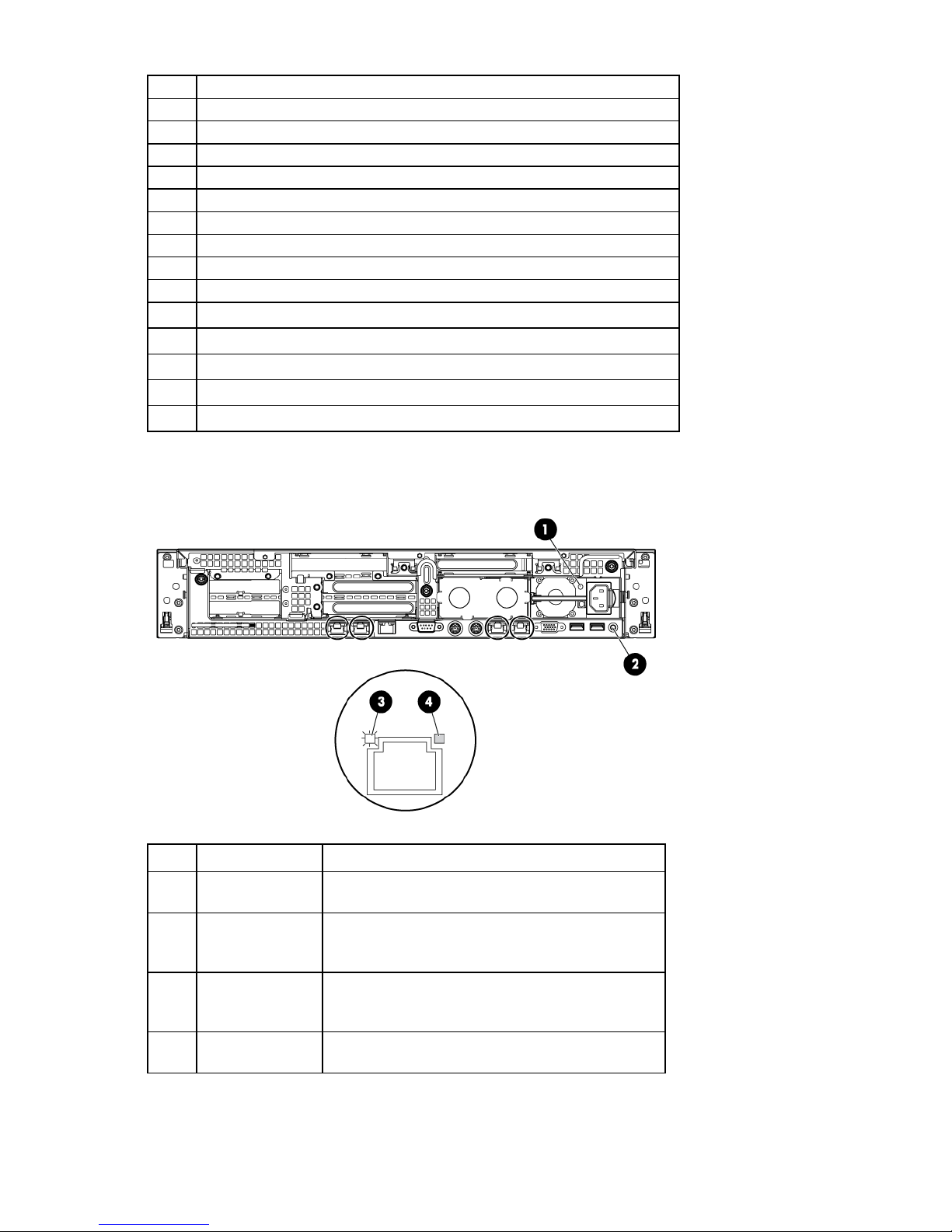
Rear panel components (DL160 G6)
The figure shown in this section is a non-hot-plug power supply model. The HP ProLiant DL160 G6 Server is
also available in a hot-plug power supply model.
Item Description
1
2
3
4
Serial connector
Video connector
USB connectors (2)
5
6
7
8
Dedicated management connector (optional)
Low-profile PCI expansion card slot
Full-height/full-length PCI expansion card slot
9
10
11
PCI cage thumbscrews (2)
NIC 1 connector
HP ProLiant servers (rack) 8
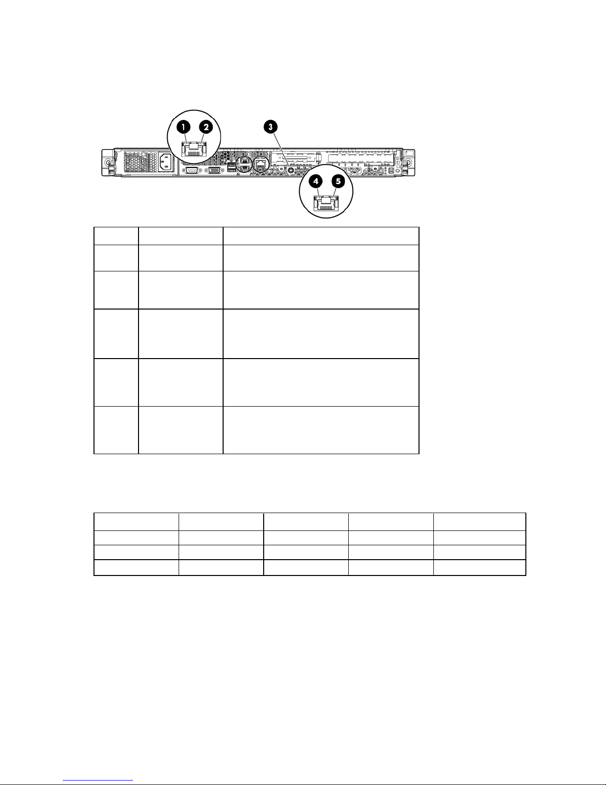
Rear panel LEDs and buttons (DL160 G6)
The figure shown in this section is a non-hot-plug power supply model. The HP ProLiant DL160 G6 Server is
also available in a hot-plug power supply model.
Item Description Status
1
2
3
4
5
NIC link LED Green = Linking at 100 Mbps speed
Off = No connection or linking at 10 Mbps speed
NIC activity LED Green = LAN is linking.
Flashing green = LAN is active.
Off = No connection
UID button/LED Blue = Identification
Flashing blue = System is being managed
remotely.
Off = Off
Dedicated
management
connector activity
Green = LAN is linking.
Flashing green = LAN is active.
Off = No connection
LED (optional)
Dedicated
management
Green = Linking at 100 Mbps speed
Off = No connection or linking at 10 Mbps speed
connector link LED
(optional)
PCI expansion slot definitions (DL160 G6)
Always install an InfiniBand PCIe HCA in slot 1 of this server.
Slot Type Length Connector Interconnect
1
1
2
PCIe2 Full x16 x16
Optional PCI-X Full 133 MHz/3.3 V 64 bit
PCIe Half x16 x4
HP ProLiant DL1000 Multi Node Servers
The DL1000 consists of up to four independent DL170h G6 servers in the 2U HP ProLiant h1000 G6 Chassis
and is available in 2-node and 4-node models. Only the 4-node model (HP ProLiant DL4x170h G6 Server)
of the HP ProLiant DL170h G6 Server is supported in the HP Cluster Platform.
HP ProLiant servers (rack) 9
HP ProLiant DL170h G6 Server
The HP ProLiant DL4x170h G6 Server is used as a compute node in HP Cluster Platform configurations.
HP ProLiant DL170h G6 Server documentation
For server-specific information, see the server documentation:
• For a complete list of features and specifications, see the HP ProLiant DL1000 Multi Node Server
QuickSpecs on the HP website
(http://h18004.www1.hp.com/products/quickspecs/13309_na/13309_na.html).
• For service information, see the HP ProLiant DL170h G6 Server Maintenance and Service Guide on the
HP website
(http://h20000.www2.hp.com/bc/docs/support/SupportManual/c01806355/c01806355.pdf).
Front panel components (DL170h G6)
Item Description
1
2
Hard drive bay (populated)
Rack-mounting thumbscrews (2)
Front panel LEDs and buttons (DL170h G6)
Item Description
1
2
3
4
5
Power button (node 3)
Health LED (node 3)
Health LED (node 4)
Power button (node 4)
Chassis UID LED button
HP ProLiant servers (rack) 10
Item Description
6
7
8
9
10
11
Health LED (node 1)
Power button (node 1)
Power button (node 2)
Health LED (node 2)
Hard drive activity LED
Hard drive fault/UID LED
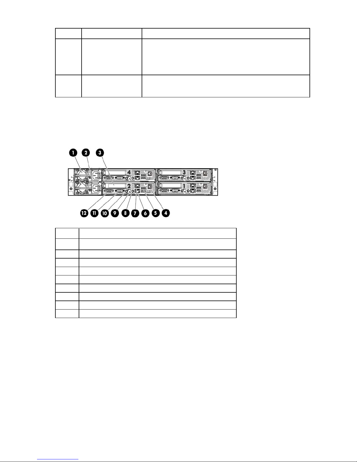
Rear panel components (DL170h G6)
The table below describes components for node 1 only. Each node contains the same components in the
same orientation, except for the power supply. The four nodes have only two power supplies.
Item Description
1
2
3
4
5
6
7
8
Video connector
PCIe2, low-profile expansion slot
Serial connector
1-Gb NIC 1 connector
1-Gb NIC 2/management connector (shared)
USB connectors (2)
Dedicated management port (IPMI) (optional)
Power supply cable connector
HP ProLiant servers (rack) 11
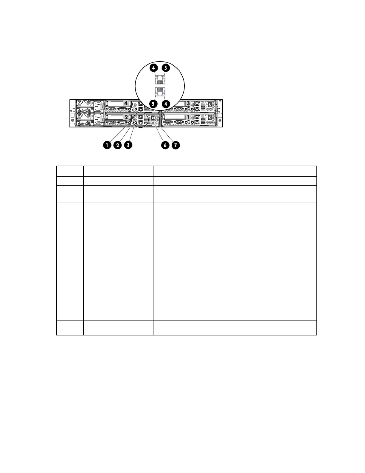
Rear panel LEDs and buttons (DL170h G6)
The table below describes LEDs for node 1 only. Each node contains the same LEDs in the same orientation.
Item Description
1
2
3
4
5
UID LED/button
Health LED
Power button
NIC activity LED
NIC link LED
PCI expansion slot definitions (DL170h G6)
The HP ProLiant DL170h G6 Server has one available low-profile PCIe2 x16 slot per node.
HP ProLiant DL2000 Multi Node Servers
The HP ProLiant DL2000 Multi Node Servers are supported in the HP Cluster Platform. The DL2000 Multi
HP ProLiant DL170e G6 Server
Node Servers consist of up to four independent DL170e G6 servers in the 2U HP ProLiant e2000 G6 Chassis.
The HP ProLiant DL170e G6 Server is used as a compute node in HP Cluster Platform configurations.
HP ProLiant DL170e G6 Server documentation
For server-specific information, see the server documentation:
• For a complete list of features and specifications, see the HP ProLiant DL2000 Multi Node Server
QuickSpecs on the HP website
(http://h18004.www1.hp.com/products/quickspecs/13847_na/13847_na.html).
• For installation and service information, see the HP ProLiant DL170e G6 Server Installation Sheet and
the HP ProLiant DL170e G6 Server Maintenance and Service Guide on the HP website
(http://www.hp.com/support/manuals).
Under servers, select ProLiant ML/DL and TC series servers, and then select HP ProLiant DL170e G6
Server series.
HP ProLiant servers (rack) 12
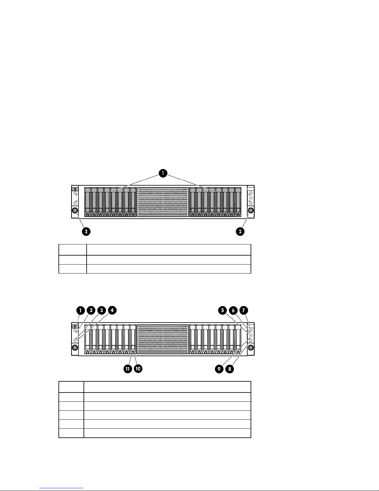
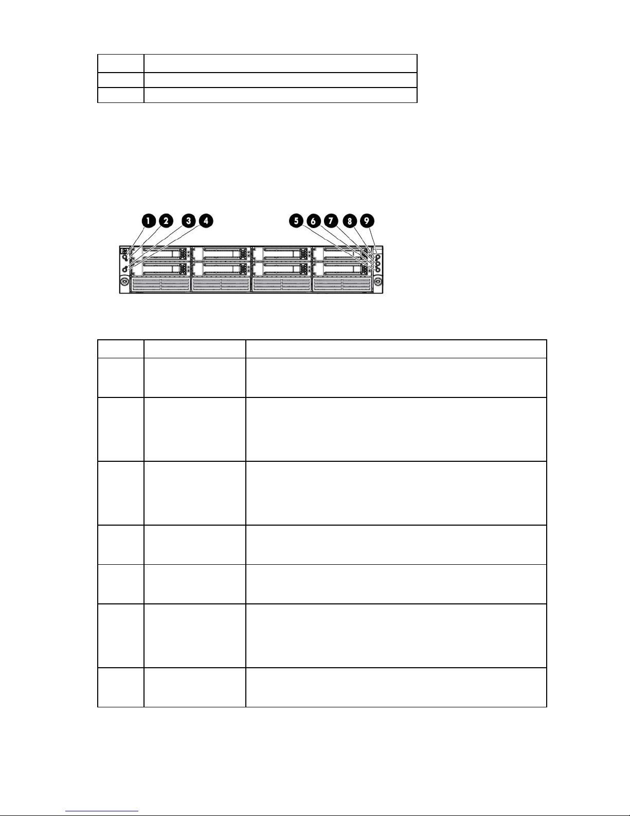
Front panel components (DL170e G6)
The HP Cluster Platform supports the following three models of the HP ProLiant DL170e G6 Server:
• Four-node server with 8-bay LFF hard drive cage
Item Description
1
2
LFF hard drive bays, populated (8)
Rack-mounting thumbscrews (2)
• Four-node server with 16-bay SFF hard drive cage
Item Description
1
2
SFF hard drive bays, populated (16)
Rack-mounting thumbscrews (2)
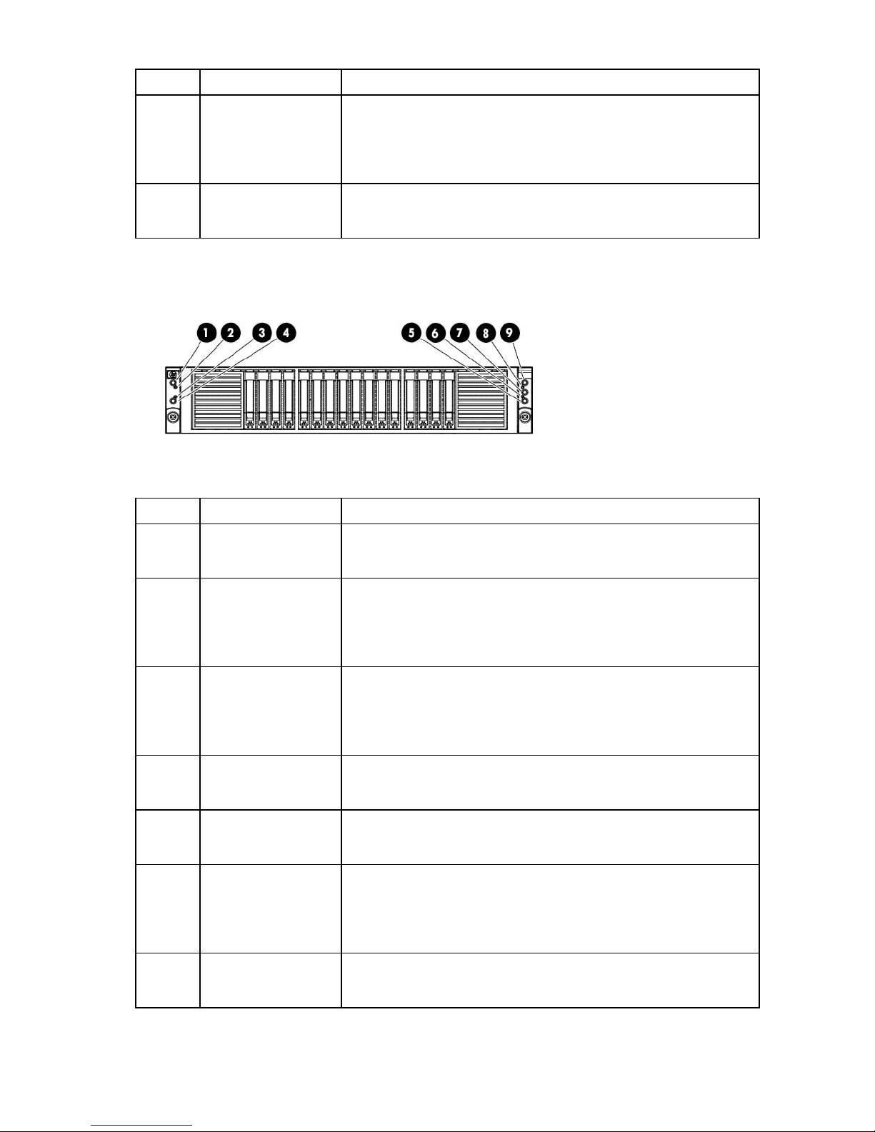
• Four-node server with 24-bay SFF hard drive cage
HP ProLiant servers (rack) 13
Item Description
1
2
SFF hard drive bays, populated (24)
Rack-mounting thumbscrews (2)
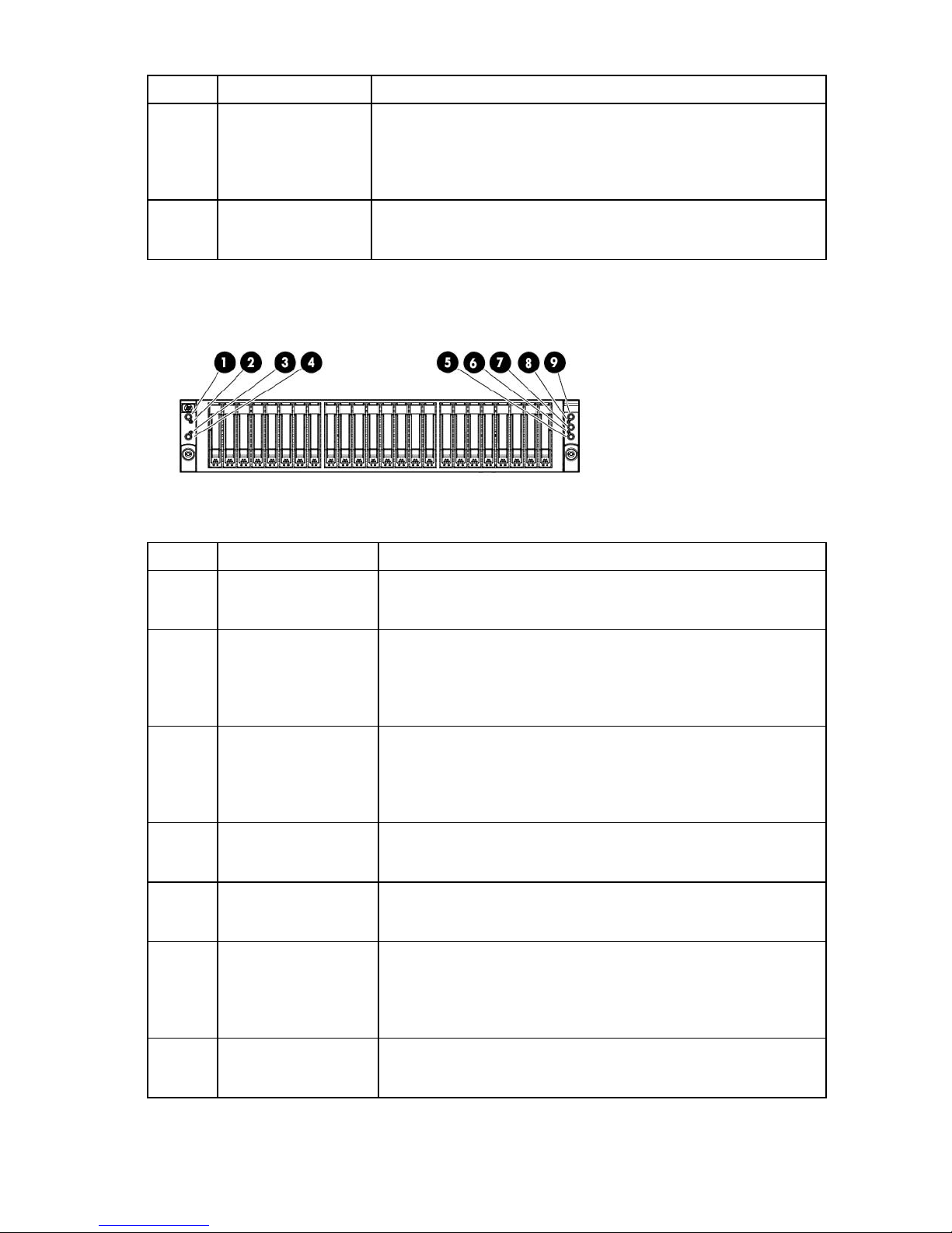
Front panel LEDs and buttons (DL170e G6)
The HP Cluster Platform supports the following three models of the HP ProLiant DL170e G6 Server:
• Four-node server with 8-bay LFF hard drive cage
Item Description Status
1
2
3
4
5
6
7
Power button (node 2) Green—Normal (system on)
Amber—The node is off or in hibernation with AC power.
Off—Off without AC power
Health LED (node 2) Green = System health is normal.
Flashing amber = System health is degraded (non-critical). For more
information, see SEL.
Flashing red = System health is critical. For more information, see SEL.
Off = System is off and health is normal.
Health LED (node 1) Green = System health is normal.
Flashing amber = System health is degraded (non-critical). For more
information, see SEL.
Flashing red = System health is critical. For more information, see SEL.
Off = System is off and health is normal.
Power button (node 1) Green—Normal (system on)
Amber—The node is off or in hibernation with AC power.
Off—Off without AC power
Power button (node 3) Green—Normal (system on)
Amber—The node is off or in hibernation with AC power.
Off—Off without AC power
Health LED (node 3) Green = System health is normal.
Flashing amber = System health is degraded (non-critical). For more
information, see SEL.
Flashing red = System health is critical. For more information, see SEL.
Off = System is off and health is normal.
Chassis UID LED button Blue = Identification is activated.
Flashing blue = System is being managed remotely.
Off = Off
HP ProLiant servers (rack) 14
Item Description Status
Power button (node 2)
Green—Normal (system on)
8
9
Health LED (node 4) Green = System health is normal.
Flashing amber = System health is degraded (non-critical). For more
information, see SEL.
Flashing red = System health is critical. For more information, see SEL.
Off = System is off and health is normal.
Power button (node 4) Green—Normal (system on)
Amber—The node is off or in hibernation with AC power.
Off—Off without AC power
• Four-node server with 16-bay SFF hard drive cage
Item Description Status
1
2
3
4
5
6
7
Health LED (node 2) Green = System health is normal.
Health LED (node 1) Green = System health is normal.
Power button (node 1) Green—Normal (system on)
Power button (node 3) Green—Normal (system on)
Health LED (node 3) Green = System health is normal.
Chassis UID LED button Blue = Identification is activated.
Amber—The node is off or in hibernation with AC power.
Off—Off without AC power
Flashing amber = System health is degraded (non-critical). For more
information, see SEL.
Flashing red = System health is critical. For more information, see SEL.
Off = System is off and health is normal.
Flashing amber = System health is degraded (non-critical). For more
information, see SEL.
Flashing red = System health is critical. For more information, see SEL.
Off = System is off and health is normal.
Amber—The node is off or in hibernation with AC power.
Off—Off without AC power
Amber—The node is off or in hibernation with AC power.
Off—Off without AC power
Flashing amber = System health is degraded (non-critical). For more
information, see SEL.
Flashing red = System health is critical. For more information, see SEL.
Off = System is off and health is normal.
Flashing blue = System is being managed remotely.
Off = Off
HP ProLiant servers (rack) 15
Item Description Status
Power button (node 2)
Green—Normal (system on)
8
9
Health LED (node 4) Green = System health is normal.
Flashing amber = System health is degraded (non-critical). For more
information, see SEL.
Flashing red = System health is critical. For more information, see SEL.
Off = System is off and health is normal.
Power button (node 4) Green—Normal (system on)
Amber—The node is off or in hibernation with AC power.
Off—Off without AC power
• Four-node server with 16-bay SFF hard drive cage
Item Description Status
1
2
3
4
5
6
7
Health LED (node 2) Green = System health is normal.
Health LED (node 1) Green = System health is normal.
Power button (node 1) Green—Normal (system on)
Power button (node 3) Green—Normal (system on)
Health LED (node 3) Green = System health is normal.
Chassis UID LED button Blue = Identification is activated.
Amber—The node is off or in hibernation with AC power.
Off—Off without AC power
Flashing amber = System health is degraded (non-critical). For more
information, see SEL.
Flashing red = System health is critical. For more information, see SEL.
Off = System is off and health is normal.
Flashing amber = System health is degraded (non-critical). For more
information, see SEL.
Flashing red = System health is critical. For more information, see SEL.
Off = System is off and health is normal.
Amber—The node is off or in hibernation with AC power.
Off—Off without AC power
Amber—The node is off or in hibernation with AC power.
Off—Off without AC power
Flashing amber = System health is degraded (non-critical). For more
information, see SEL.
Flashing red = System health is critical. For more information, see SEL.
Off = System is off and health is normal.
Flashing blue = System is being managed remotely.
Off = Off
HP ProLiant servers (rack) 16
Item Description Status
8
9
Health LED (node 4) Green = System health is normal.
Flashing amber = System health is degraded (non-critical). For more
information, see SEL.
Flashing red = System health is critical. For more information, see SEL.
Off = System is off and health is normal.
Power button (node 4) Green—Normal (system on)
Amber—The node is off or in hibernation with AC power.
Off—Off without AC power
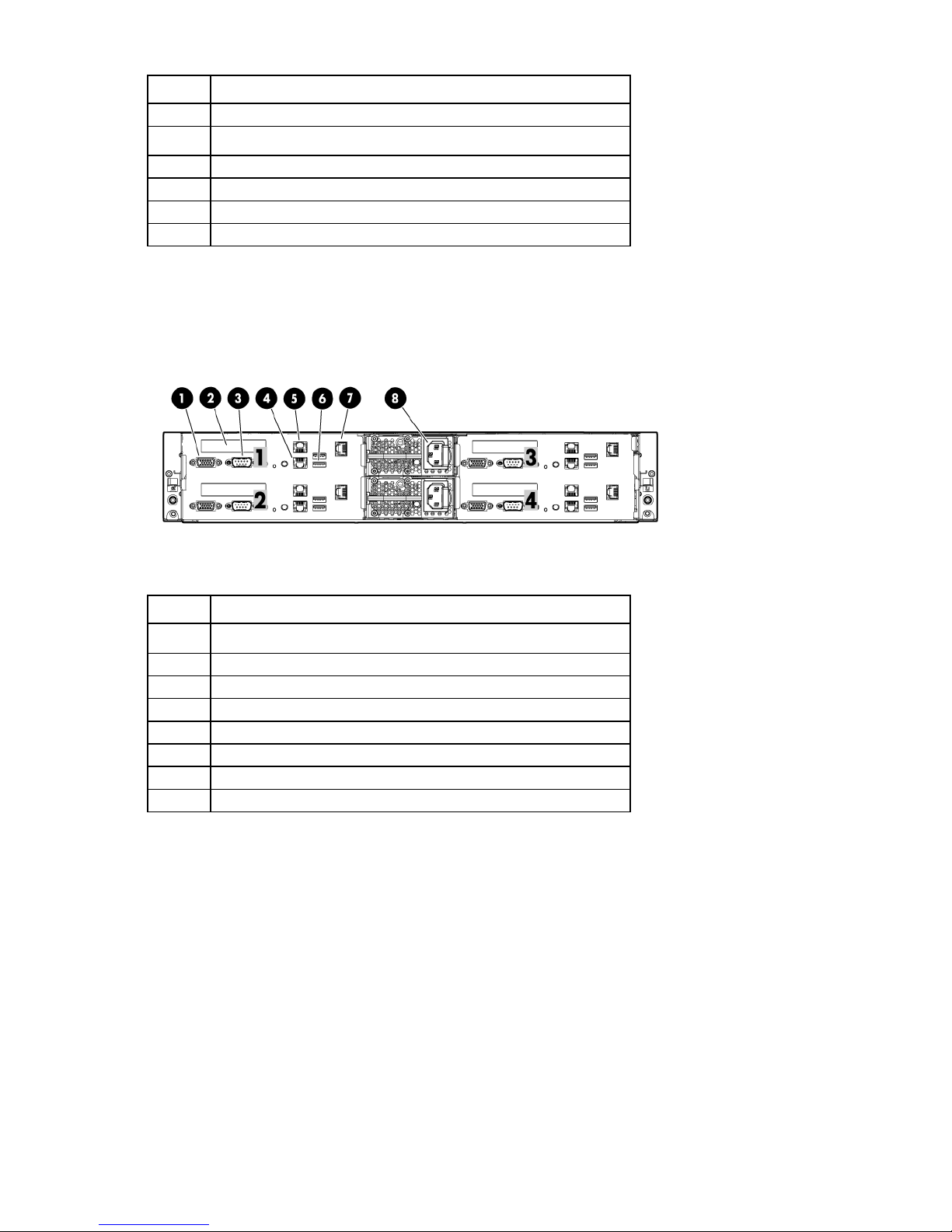
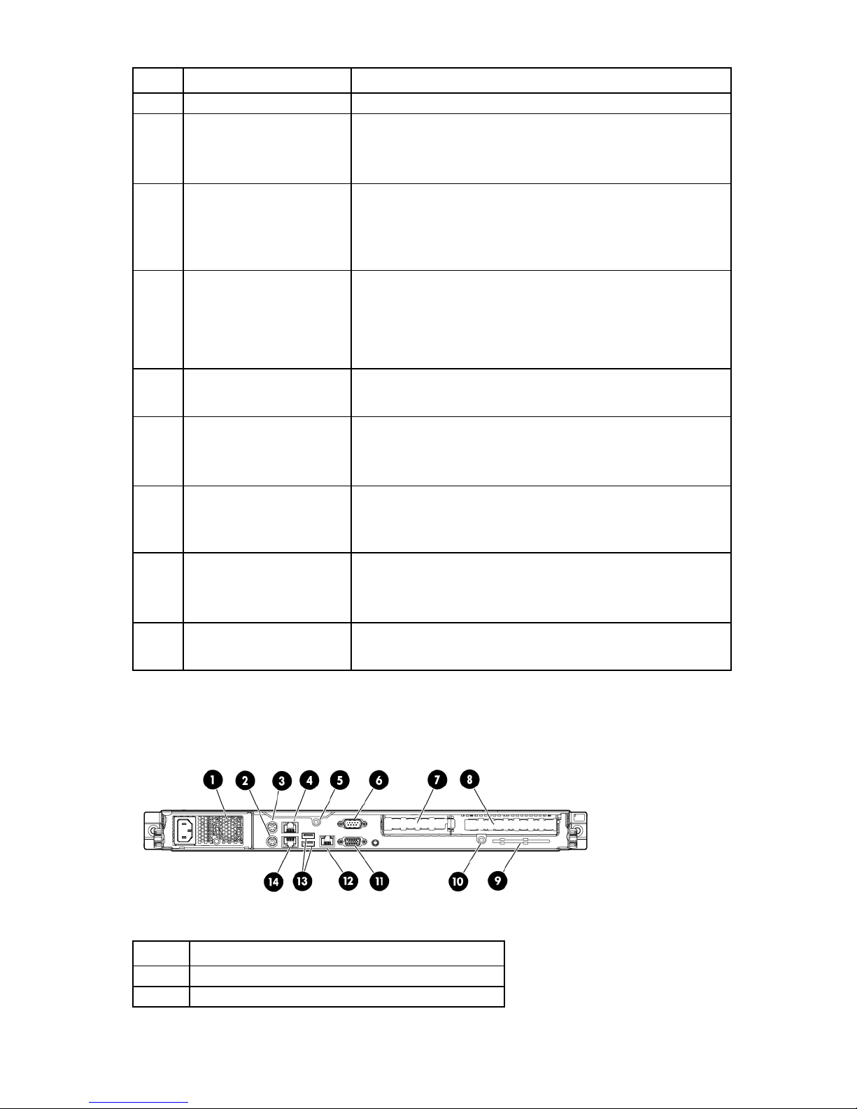
Rear panel components (DL170e G6)
The table below describes components for node 1 only. Each node contains the same components in the
same orientation, except for the power supply. The four nodes have only two power supplies.
Item Description
1
2
3
4
5
6
7
8
9
Power supply 2
Power supply 1
PCIe2, low-profile expansion slot
Dedicated management port (optional)
USB connectors (2)
1-Gb NIC 1 connector
1-Gb NIC 2/management connector (shared)
Serial connector
Video connector
HP ProLiant servers (rack) 17
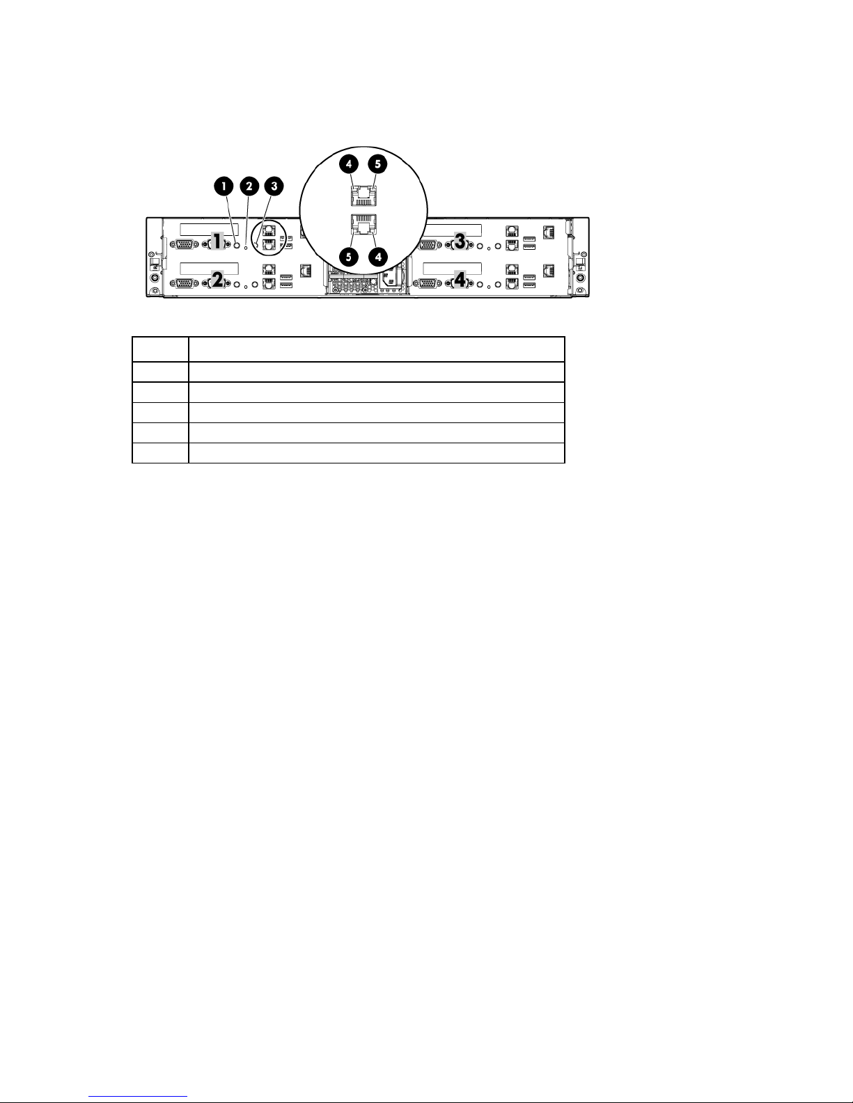
Rear panel LEDs and buttons (DL170e G6)
The table below describes LEDs for node 1 only. Each node contains the same LEDs in the same orientation.
Item Description Status
1
2
3
4
5
6
7
UID LED/button —
Health LED —
Power button —
LAN network speed LED 10/100 speed
Green—The LAN connection is using a 100 Mbps link.
Off—The LAN connection is using a 10 Mbps link.
GbE speed
Green—The LAN connection is using a 100 Mbps link.
Flashing green—The LAN connection is using a 10 Mbps/100 Mbps
link for port identification.
Amber—The LAN connection is using a 1 Gbps link.
Flashing amber—The LAN connection is using a 1 Gbps link for port
identification.
Off—The LAN connection is using a 10 Mbps link.
LAN activity status LED Green—Normal LAN connection. No activity.
Flashing green—Ongoing network data activity
Off—No network data activity or no connection
Management port activity
LED (optional)
Management port link LED
Green—Linking at 100 Mbps speed
Off—No connection or linking at 10 Mbps speed
Flashing amber—LAN is active.
(optional)
PCI expansion slot definitions (DL170e G6)
The HP ProLiant DL170e G6 Server has one available low-profile PCIe2 x16 slot per node.
HP ProLiant DL380 G6 Server
The HP ProLiant DL380 G6 Server is used as a control node in HP Cluster Platform configurations.
HP ProLiant servers (rack) 18
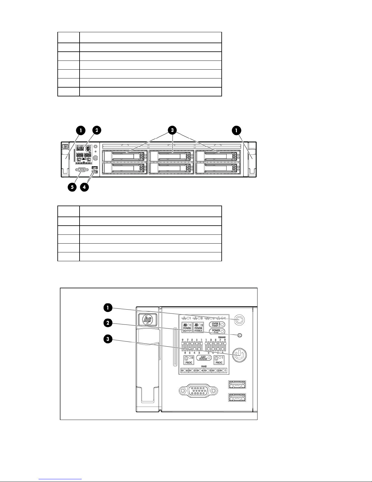
HP ProLiant DL380 G6 Server documentation
Systems Insight Display
For server-specific information, see the server documentation:
• For a complete list of features and specifications, see the HP ProLiant DL380 Generation 6 (G6)
QuickSpecs on the HP website
(http://h18004.www1.hp.com/products/quickspecs/13234_na/13234_na.pdf).
• For installation and service information, see the HP ProLiant DL380 G6 Server User Guide and the HP
ProLiant DL380 G6 Server Maintenance and Service Guide on the HP website
(http://www.hp.com/support/manuals).
Under servers, select ProLiant ML/DL and TC series servers, and then select HP ProLiant DL380 G6
Server series.
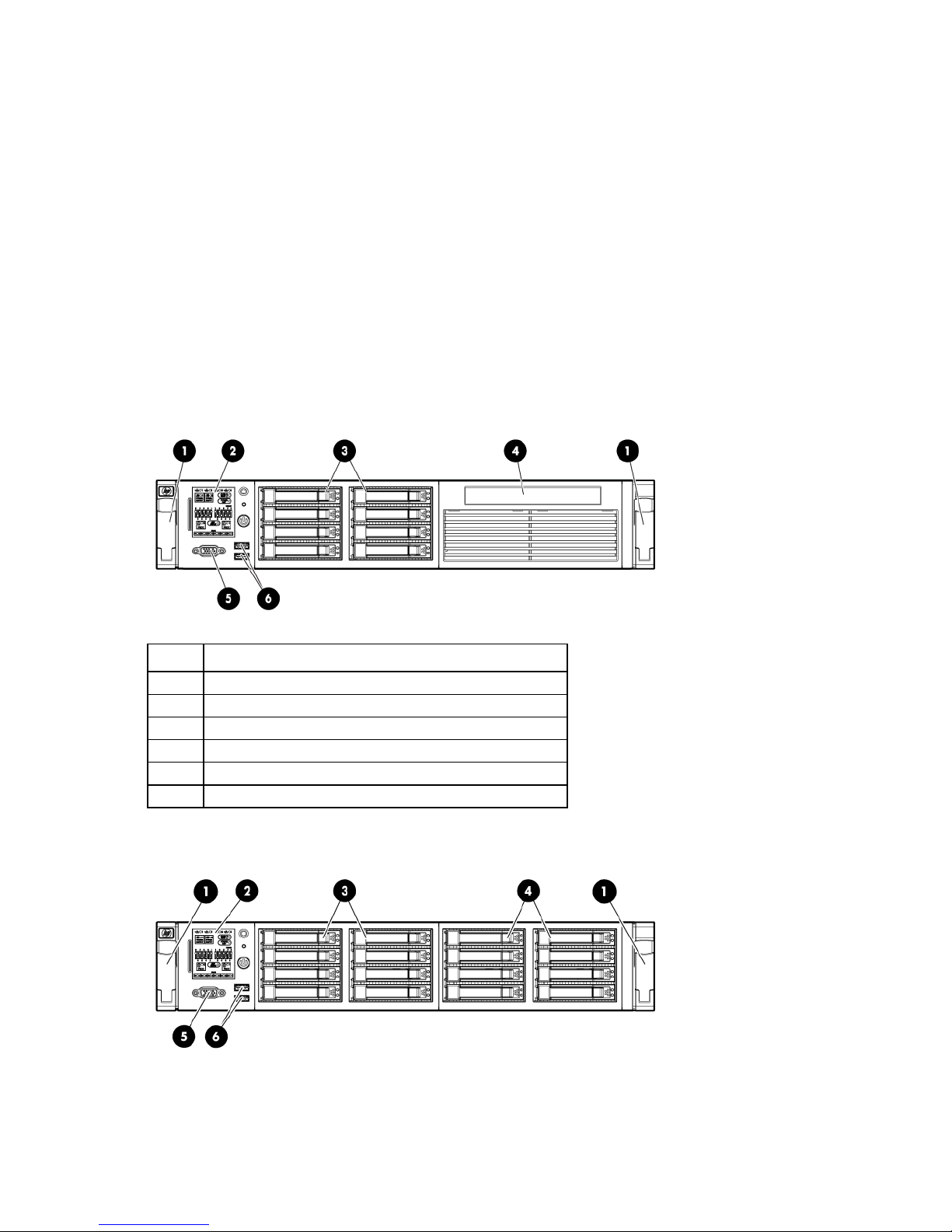
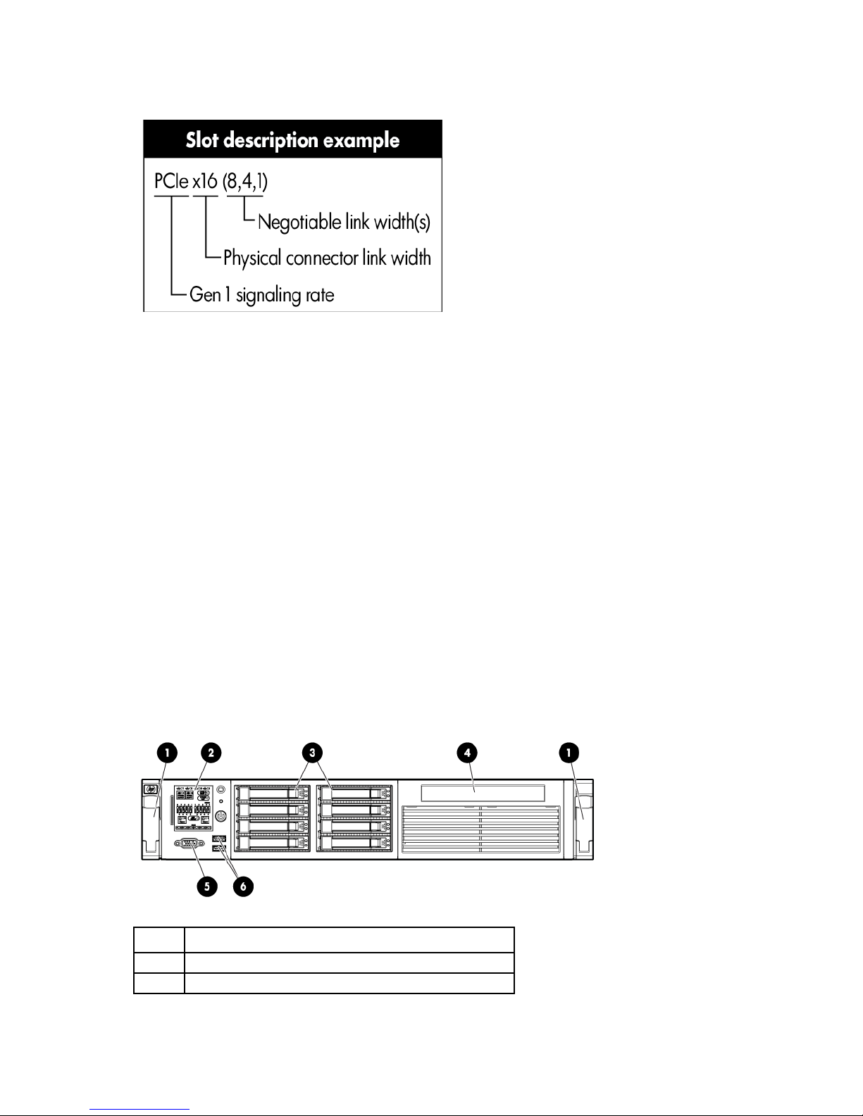
Front panel components (DL380 G6)
• SFF hard drive model
Item Description
1
2
3
4
5
6
Quick release levers (2)
Hard drive bays (8)
SATA optical drive bay
Video connector
USB connectors (2)
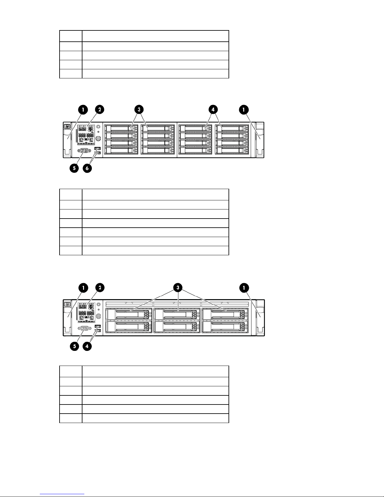
• SFF hard drive model with optional hard drive cage
HP ProLiant servers (rack) 19
Hard drive bays (6)
Item Description
1
2
3
4
5
6
Quick release levers (2)
Systems Insight Display
Hard drive bays (8)
Optional hard drive bays (8)
Video connector
USB connectors (2)
• LFF hard drive model
Item Description
1
2
3
4
5
Quick release levers (2)
Systems Insight Display
USB connectors (2)
Video connector
Front panel LEDs and buttons (DL380 G6)
HP ProLiant servers (rack) 20
Serial connector
Item Description Status
1
2
3
UID LED and button Blue = Activated
Flashing blue = System being remotely managed
Off = Deactivated
System health LED Green = Normal
Amber = System degraded
Red = System critical
To identify components in degraded or critical state, see "Systems
Insight Display LEDs" in the server user guide.
Power On/Standby button
and system power LED
Green = System on
Amber = System is in standby, but power is still applied.
Off = Power cord not attached or power supply failure
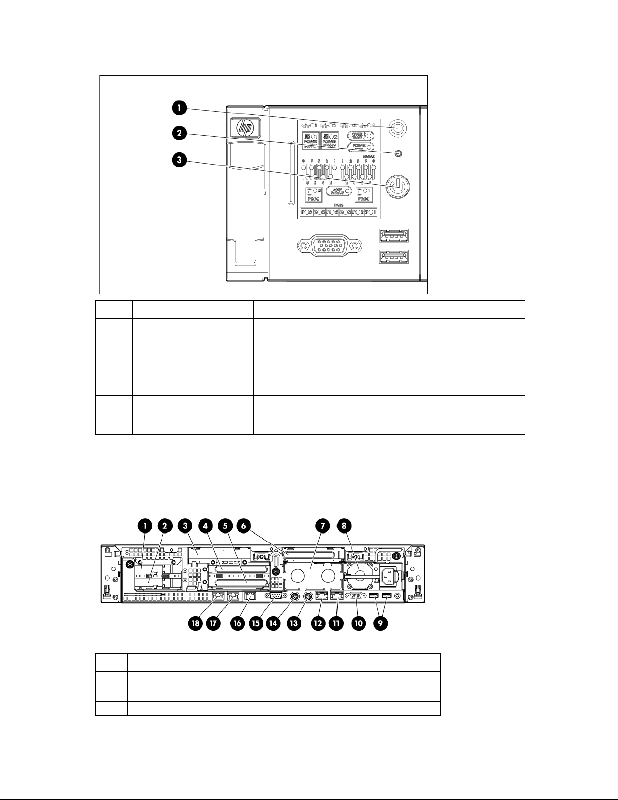
Rear panel components (DL380 G6)
Item Description
1
2
3
4
5
6
7
8
9
10
11
12
13
14
15
16
17
18
PCI slot 5
PCI slot 6
PCI slot 4
PCI slot 2
PCI slot 3
PCI slot 1
Power supply bay 2
Power supply bay 1 (populated)
USB connectors (2)
Video connector
NIC 1 connector
NIC 2 connector
Mouse connector
Keyboard connector
iLO 2 connector
NIC 3 connector
NIC 4 connector
HP ProLiant servers (rack) 21

Rear panel LEDs and buttons (DL380 G6)
NIC/iLO 2 activity
Green = Network activity
Item Description Status
1
2
3
4
Power supply LED Green = Normal
Off = System is off or power supply has failed
UID LED/button Blue = Activated
Flashing blue = System being managed remotely
Off = Deactivated
LED
NIC/iLO 2 link LED Green = Network link
Flashing green = Network activity
Off = No network activity
Off = No network link
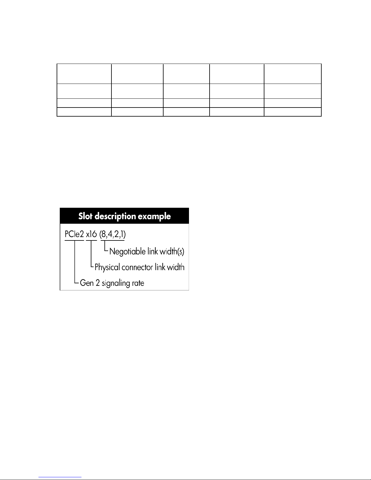
PCI expansion slot definitions (DL380 G6)
Always install an InfiniBand PCIe HCA in slot 4 of this server.
Primary
(slot - form factor)
1 - FL/FH
2 - HL/FH
3 - HL/FH
Secondary
(slot - form factor)
4 - FL/FH PCIe x16 (8,4,1) PCIe x16 (16,8,4,1) PCI-X 64-bit/133-MHz
5 - LP PCIe x8 (4,1) — PCIe x16 (8,4,1)
6 - LP PCIe x8 (4,1) — PCIe x8 (4,1)
PCIe riser
slot description
PCIe x16 riser
slot description
PCIe/PCI-X riser
slot description
Notes:
• "Primary" denotes the risers are installed in the primary riser connector.
• "Secondary" denotes the risers are installed in the secondary riser connector.
• FL/FH denotes full-length, full-height. HL/FH denotes half-length, full-height. LP denotes low profile.
HP ProLiant servers (rack) 22
• The PCIe x16 riser supports a maximum power of 150W with an HP power cable. The cable supplied
with the riser must be used for PCIe card wattages greater than 75W.
HP ProLiant DL380 G7 Server
HP ProLiant DL380 G7 Server documentation
Front panel components (DL380 G7)
The HP ProLiant DL380 G7 Server is used as a control node in HP Cluster Platform configurations.
For server-specific information, see the server documentation:
• For a complete list of features and specifications, see the HP ProLiant DL380 Generation 7 (G7)
QuickSpecs on the HP website
(http://h18004.www1.hp.com/products/quickspecs/13595_na/13595_na.html).
• For installation and service information, see the HP ProLiant DL380 G7 Server User Guide and the HP
ProLiant DL380 G7 Server Maintenance and Service Guide on the HP website
(http://www.hp.com/support/manuals).
Under servers, select ProLiant ML/DL and TC series servers, and then select HP ProLiant DL380 G7
Server series.
• SFF hard drive model
Item Description
1
2
Quick release levers (2)
Systems Insight Display
HP ProLiant servers (rack) 23
Item Description
Video connector
3
4
5
6
Hard drive bays
SATA optical drive bay
Video connector
USB connectors (2)
• SFF hard drive model with optional hard drive cage
Item Description
1
2
3
4
5
6
Quick release levers (2)
Systems Insight Display
Hard drive bays
Hard drive bays (optional)
USB connectors (2)
• LFF hard drive model
Item Description
1
2
3
4
5
Quick release levers (2)
Systems Insight Display
Hard drive bays
USB connectors (2)
Video connector
HP ProLiant servers (rack) 24
Front panel LEDs and buttons (DL380 G7)
Item Description Status
1
2
3
*To identify components in degraded or critical state, see "Systems Insight Display LEDs" in the HP ProLiant DL380 G7
Server User Guide. For more information, see "HP ProLiant DL380 G7 Server documentation (on page 23)."
UID LED and button Blue = Activated
Flashing blue = System being remotely managed
Off = Deactivated
System health LED Green = Normal
Amber = System degraded*
Red = System critical*
Power On/Standby button
and system power LED
Green = System on
Amber = System is in standby, but power is still applied.
Off = Power cord not attached or power supply failure
Rear panel components (DL380 G7)
Item Description
1
2
3
PCI slot 5
PCI slot 6
PCI slot 4
HP ProLiant servers (rack) 25
4
PCI slot 2
5
6
7
8
9
10
11
12
13
14
15
16
17
18
PCI slot 3
PCI slot 1
Power supply bay 2
Power supply bay 1 (populated)
USB connectors (2)
Video connector
NIC 1 connector
NIC 2 connector
Mouse connector
Keyboard connector
Serial connector
iLO connector
NIC 3 connector
NIC 4 connector
Rear panel LEDs and buttons (DL380 G7)
Item Description Status
1
2
3
4
Power supply LED Green = Normal
UID LED/button Blue = Activated
NIC/iLO activity
LED
NIC/iLO link LED Green = Network link
Off = System is off or power supply has failed.
Flashing blue = System being managed remotely
Off = Deactivated
Green = Network activity
Flashing green = Network activity
Off = No network activity
Off = No network link
HP ProLiant servers (rack) 26
PCI expansion slot definitions (DL380 G7)
Always install an InfiniBand PCIe HCA in slot 4 of this server.
Secondary
(slot - form factor)
4 - FL/FH
5 - LP
6 - LP
Notes:
• "Primary" denotes the risers are installed in the primary riser connector.
• "Secondary" denotes the risers are installed in the secondary riser connector.
• Installing the risers listed in the table above in either the primary or secondary riser connectors
determines the form factor of the PCI cards supported by those risers.
• FL/FH denotes full-length, full-height. HL/FH denotes half-length, full-height. LP denotes low profile.
• The PCIe2 x16 riser supports a maximum power of 150 W with an HP power cable. This cable must be
used for PCIe card wattages greater than 75 W.
Primary
(slot - form factor)
1 - FL/FH PCIe2 x16 (8,4,1) PCIe2 x16
2 - HL/FH PCIe2 x8 (4,1) — PCIe2 x16 (8,4,1)
3 - HL/FH PCIe2 x8 (4,1) — PCIe2 x8 (4,1)
PCIe2 riser
slot description
PCIe2 x16 riser
slot description
(16,8,4,1)
PCIe2/PCI-X riser
slot description
PCI-X 64 bit/133 MHz
HP ProLiant Rack Servers (AMD Opteron)
Several HP ProLiant AMD Opteron servers are supported in HP Cluster Platform solutions. This section
presents information for the HP ProLiant servers that are used in HP Cluster Platform solutions only. The
content in this section includes the following additional information for the HP ProLiant AMD Opteron servers:
• Front and rear views
• InfiniBand HCA PCI slot assignment
• Specific cable management instructions, if necessary
HP ProLiant DL165 G6 Server
• HP Cluster Platform specific maintenance instructions, if applicable
The HP ProLiant DL165 G6 Server is used as a control node and a compute node in HP Cluster Platform
configurations.
HP ProLiant servers (rack) 27

HP ProLiant DL165 G6 Server documentation
For server-specific information, see the server documentation:
• For a complete list of features and specifications, see the HP ProLiant DL165 Generation 6 (G6)
QuickSpecs on the HP website
(http://h18004.www1.hp.com/products/quickspecs/13367_na/13367_na.pdf).
• For installation and service information, see the HP ProLiant DL100 Series Server User Guide and the HP
ProLiant DL165 G6 Server Maintenance and Service Guide on the HP website
(http://www.hp.com/support/manuals).
Under servers, select ProLiant ML/DL and TC series servers, and then select HP ProLiant DL165 G6
Server series.
Front panel components (DL165 G6)
Item Description
1
2
3
4
5
Optical drive
Serial label pull tab
Front USB connector (2)
Rack mounting thumbscrews (2)
Hard drive bays (4)
Front panel LEDs and buttons (DL165 G6)
Item Description Status
1
Optical drive activity LED Flashing green = Ongoing drive activity
HP ProLiant servers (rack) 28
Item Description Status
Power button/LED
Green = Normal (system on)
Off = No drive activity exists.
2
3
4
Health LED Green = System health is normal.
Amber = System health is degraded.
Red = System health is critical.
Off = System health is normal (when in standby mode).
NIC 1 link/activity LED Green = Network link exists.
Flashing green = Network link and activity exist.
Off = No network link exists.
If power is off, view the LEDs on the RJ-45 connector on the rear of the
server.
NIC 2 link/activity LED Green = Network link exists.
Flashing green = Network link and activity exist.
Off = No network link exists.
If power is off, view the LEDs on the RJ-45 connector on the rear of the
server.
5
Drive activity LED Green = Drive activity is normal.
Off = No drive activity exists.
6
Amber = System is in standby, but power is still applied.
Off = Power cord is not attached, or the power supply has failed.
7
UID LED/button Blue = Identification is activated.
Flashing blue = System is being managed remotely.
Off = Identification is deactivated.
8
Drive fault/identification LED Blue = Drive identified
Amber = Drive failure
Flashing amber = Fault-process activity
Off = No fault-process activity
9
Drive activity LED Flashing green = Drive activity
Off = No drive activity
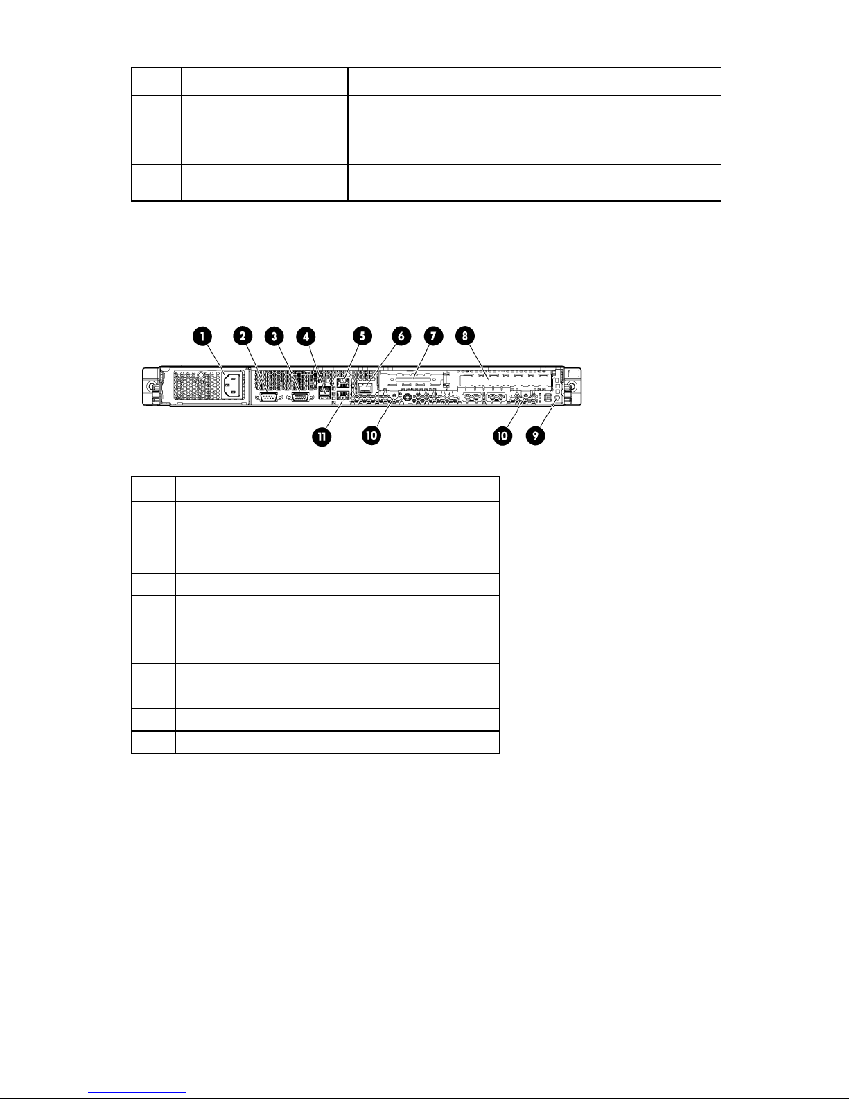
Rear panel components (DL165 G6)
Item Description
1
2
Power supply cable connector
Keyboard connector (purple)
HP ProLiant servers (rack) 29
 Loading...