

Page 1

HP CloudSystem 8.0 Administrator Guide
Abstract
This information is for use by administrators using HP CloudSystem Foundation and Enterprise Software 8.0, who are assigned
to configure and provision compute resources for deployment and use in virtual data centers. This guide provides instructions
on using the CloudSystem Foundation Console and Portal user interfaces, as well as introducing the CloudSystem command
line interface. Built on OpenStack technology, CloudSystem supports most OpenStack Havana functionality available in Nova,
Keystone, Neutron, Cinder, Glance, and Horizon components. This guide describes limitations on this OpenStack functionality
in this software release. Additionally, this guide provides information necessary to configure the full use of CloudSystem
Enterprise.
HP Part Number: 5900-3376
Published: March 2014
Edition: 1
Page 2

© Copyright 2014 Hewlett-Packard Development Company, L.P.
Microsoft® and Windows® are U.S. registered trademarks of the Microsoft group of companies.
Red Hat® is a registered trademark of Red Hat, Inc. in the United States and other countries.
Confidential computer software. Valid license from HP required for possession, use or copying. Consistent with FAR 12.211 and 12.212, Commercial
Computer Software, Computer Software Documentation, and Technical Data for Commercial Items are licensed to the U.S. Government under
vendor's standard commercial license.
The information contained herein is subject to change without notice. The only warranties for HP products and services are set forth in the express
warranty statements accompanying such products and services. Nothing herein should be construed as constituting an additional warranty. HP shall
not be liable for technical or editorial errors or omissions contained herein.
The open source code used by HP CloudSystem is available on the HP web at http://www.hp.com/software/opensource.
Page 3

Contents
I Understanding HP CloudSystem...................................................................11
1 Welcome to HP CloudSystem Administrator Guide....................................12
Features............................................................................................................................13
2 Concepts and architecture.....................................................................15
How it works.....................................................................................................................15
Associated appliances...................................................................................................16
Storage........................................................................................................................17
Physical servers.............................................................................................................17
User authentication........................................................................................................17
OpenStack technology...................................................................................................18
CloudSystem Foundation at a glance....................................................................................18
CloudSystem Foundation components..............................................................................18
Networks in CloudSystem Foundation..............................................................................19
Network tasks and user roles.....................................................................................20
CloudSystem Enterprise at a glance......................................................................................20
CloudSystem Enterprise components................................................................................20
3 Security in CloudSystem.........................................................................22
Best practices for maintaining a secure appliance..................................................................22
Enabling or disabling authorized services access...................................................................24
Restricting console access...................................................................................................24
Best practices for browser use..............................................................................................24
Managing certificates from a browser...................................................................................25
Self-signed certificate.....................................................................................................25
Protecting credentials..........................................................................................................25
4 Installation...........................................................................................27
5 Navigating the CloudSystem Console GUI...............................................28
About the graphical user interface........................................................................................28
Use the banner and main menu to navigate..........................................................................29
About Activity....................................................................................................................29
About alerts.................................................................................................................30
About tasks..................................................................................................................31
About the Activity sidebar..............................................................................................31
Activity states................................................................................................................31
Activity statuses.............................................................................................................32
Icon descriptions................................................................................................................32
Status and severity icons................................................................................................32
User control icons..........................................................................................................33
Informational icons........................................................................................................34
Browser requirements.........................................................................................................34
Required browser plug-ins and settings.............................................................................34
Supported browser features and settings..........................................................................34
Search resources................................................................................................................35
6 Support and other resources...................................................................37
Information to collect before contacting HP............................................................................37
Understanding the audit log...........................................................................................37
Download audit logs.....................................................................................................38
Create a support dump file.............................................................................................39
Enable or disable services access....................................................................................40
Contents 3
Page 4

How to contact HP.............................................................................................................41
Registering for software technical support and update service..................................................41
HP authorized resellers.......................................................................................................41
Documentation feedback....................................................................................................41
Related information............................................................................................................41
HP CloudSystem documents............................................................................................42
HP Software documents.................................................................................................42
Finding documents on the HP Software Product Manuals web site...................................42
HP Insight Management documents.................................................................................43
Third-party documents....................................................................................................43
HP 3PAR StoreServ Storage documents............................................................................43
Finding documents on the HP Support Center web site..................................................43
HP ProLiant servers documents........................................................................................44
II CloudSystem Foundation appliances management........................................45
7 Manage the Foundation appliances........................................................46
About managing the appliance...........................................................................................46
About Foundation appliance settings....................................................................................46
Viewing Foundation appliance settings............................................................................46
Change the appliance host name, IP address, subnet mask, or gateway address...................46
Change the DNS server.................................................................................................47
About backup and restore operations for CloudSystem Foundation...........................................47
Shut down the appliance....................................................................................................47
Restart the appliance..........................................................................................................47
Reboot Foundation appliances.............................................................................................48
Update Foundation appliances............................................................................................48
Disassemble a CloudSystem installation................................................................................50
8 Manage users and groups.....................................................................52
About user roles.................................................................................................................52
Add a fully authorized local user (Infrastructure administrator)..................................................53
About directory service authentication..................................................................................53
Configuring CloudSystem to use Active Directory or OpenLDAP directory authentication..............55
Add a directory service..................................................................................................55
Determining search context when editing a directory.........................................................56
Editing Active Directory search context........................................................................56
Editing OpenLDAP search context...............................................................................57
Limitations: Directory tree...........................................................................................58
Limitations: Directory schema.....................................................................................58
Add a directory server...................................................................................................58
Add a directory group...................................................................................................59
Set an authentication directory service as the default directory............................................60
Allow local logins..............................................................................................................61
Disable local logins............................................................................................................61
Reset the administrator password.........................................................................................61
9 Manage licenses..................................................................................63
About licenses...................................................................................................................63
License keys..................................................................................................................64
Managing license compliance........................................................................................65
Add a license key to the appliance......................................................................................65
License key format..............................................................................................................65
View license details............................................................................................................66
10 Manage security.................................................................................67
Access to the appliance console..........................................................................................67
4 Contents
Page 5

Downloading and importing a self-signed certificate...............................................................67
Verifying a certificate.........................................................................................................68
III Resource configuration in CloudSystem Foundation.......................................69
11 Overview: Configuring compute resources..............................................70
Configuring cloud resources................................................................................................70
Maximum supported configuration values for each CloudSystem .............................................71
12 Network configuration.........................................................................73
About Cloud Networking....................................................................................................73
Cloud Management Network.........................................................................................73
Can I edit cloud networking after compute nodes are activated?.........................................73
Edit Cloud Networking..................................................................................................73
About Provider Networks....................................................................................................74
Provider networks in the cloud.........................................................................................74
Managing provider networks..........................................................................................74
Add Provider Network...................................................................................................74
Delete Provider Network................................................................................................75
About Private Networks......................................................................................................76
Private Networks in the cloud..........................................................................................76
Managing private networks............................................................................................76
Understanding private networks data..........................................................................76
Add VLAN IDs ........................................................................................................76
Delete Private Network VLAN....................................................................................77
About the External Network................................................................................................77
Configuring the External Network....................................................................................77
Creating the External Network subnet.........................................................................77
Creating an External Network router...........................................................................79
Assigning floating IP addresses to instances.................................................................79
13 Integrated tool connectivity and configuration.........................................81
Managing integrated tools..................................................................................................81
HP Operations Orchestration Central....................................................................................81
Using OO Central workflows..........................................................................................81
VMware vCenter Server......................................................................................................82
Register VMware vCenter Server.....................................................................................82
14 Image management.............................................................................84
About Images....................................................................................................................84
Images in the cloud.......................................................................................................84
Managing images.........................................................................................................84
Image metadata.......................................................................................................85
Can I delete images after they are provisioned?...........................................................85
Creating and obtaining images...........................................................................................85
Setting custom attributes on Microsoft Windows images.....................................................85
Create image from a snapshot of a virtual machine...........................................................86
Add Image.......................................................................................................................86
Edit Image........................................................................................................................87
Delete Image.....................................................................................................................88
15 Storage configuration..........................................................................89
Managing Storage.............................................................................................................89
Managing block storage drivers......................................................................................89
Understanding block storage drivers data....................................................................89
Add Block Storage Drivers..................................................................................................89
Edit Block Storage Drivers...................................................................................................90
Delete Block Storage Drivers................................................................................................91
Contents 5
Page 6

About volume types............................................................................................................91
How are volume types used?..........................................................................................91
Managing volume types.................................................................................................91
Understanding volume types data...............................................................................91
What is the benefit of thin provisioning?......................................................................92
Add Volume Types........................................................................................................92
Edit Volume Types.........................................................................................................93
Delete Volume Types......................................................................................................93
About Volumes..................................................................................................................93
Managing Volumes.......................................................................................................93
Understanding Volumes data.....................................................................................94
Create volumes in the CloudSystem Portal.........................................................................94
Attach a volume to a VM instance in the CloudSystem Portal...............................................94
Delete Volumes.............................................................................................................95
16 Compute node creation........................................................................96
Preparing compute nodes...................................................................................................96
Creating ESX compute hypervisors.......................................................................................96
Configuring networks.........................................................................................................97
Configuring security groups for instances in an ESX cluster......................................................98
Configuring iSCSI on ESX compute hosts..........................................................................98
Configuring networking for the VMkernel.....................................................................98
Setting the discovery address and target name of the storage system...............................98
Creating KVM compute nodes.............................................................................................99
Applying CloudSystem requirements to the KVM compute node...........................................99
Creating a local YUM repository and validating dependencies......................................99
Configuring CloudSystem compute node network settings............................................101
17 Compute node management...............................................................103
About Compute Nodes.....................................................................................................103
Compute nodes in the cloud.........................................................................................103
Managing compute nodes...........................................................................................103
Can I delete compute nodes from the cloud?..............................................................103
Understanding compute node data...........................................................................104
Adding compute nodes to the cloud..............................................................................104
Calculating the number of instances that can be provisioned to a compute node.................105
Import a cluster................................................................................................................105
Activate a compute node..................................................................................................105
Deactivate a compute node...............................................................................................106
Delete a compute node.....................................................................................................107
18 Virtual machine configuration for compute services................................108
About virtual machine instances.........................................................................................108
Managing virtual machine instances..............................................................................108
Start instance..............................................................................................................108
Reboot instance..........................................................................................................109
Delete instance...........................................................................................................109
About Flavors..................................................................................................................109
Flavors in the cloud.....................................................................................................110
Manage flavors..........................................................................................................110
Add Flavor.................................................................................................................110
Can I delete a flavor that was used to create an instance?................................................110
Delete Flavor..........................................................................................................111
19 Monitor resource use and allocation in CloudSystem Console.................112
About the Console Dashboard...........................................................................................112
Dashboard status indicators..........................................................................................113
6 Contents
Page 7

Interpreting the Dashboard data........................................................................................114
Compute....................................................................................................................114
Network....................................................................................................................114
Storage......................................................................................................................115
IV Cloud service provisioning, deployment, and service management in
CloudSystem Portal....................................................................................116
20 Provision a cloud in Foundation..........................................................117
Launching a virtual machine instance in the CloudSystem Portal.............................................117
Create a security group................................................................................................118
Create a key pair........................................................................................................119
Create a Private network..............................................................................................119
Launching an instance using CloudSystem Portal.............................................................119
Create a volume to attach to an instance........................................................................120
21 Monitor and manage infrastructure services in CloudSystem Portal...........122
Monitoring allocation and usage in CloudSystem Console.....................................................122
V Understanding CloudSystem Enterprise......................................................123
22 About CloudSystem Enterprise............................................................124
About the Enterprise appliance..........................................................................................124
Enterprise in the cloud.................................................................................................124
Multitenancy in Enterprise............................................................................................125
23 Install Enterprise................................................................................126
Before installing Enterprise................................................................................................126
Install the Enterprise appliance..........................................................................................126
24 Enterprise appliance management......................................................128
Managing the Enterprise appliance....................................................................................128
Logging in and changing the default HP CSA and Marketplace Portal password......................128
Update the Enterprise appliance........................................................................................130
Uninstall the Enterprise appliance......................................................................................132
Enterprise appliance settings.............................................................................................132
Viewing Enterprise appliance settings............................................................................132
25 Cloud service provisioning and deployment in Enterprise.......................134
Using HP CSA to deploy virtual machine instances to the cloud..............................................134
Using HP CSA to create a design and deploy an offering......................................................134
Set up a template........................................................................................................135
Create a server group..................................................................................................135
Connect a network to the server group...........................................................................136
Create an offering.......................................................................................................136
Deploy an offering......................................................................................................137
VI Troubleshooting reference.......................................................................138
26 Use activities and alerts to troubleshoot errors.......................................139
Basic troubleshooting techniques........................................................................................139
Alerts do not behave as expected......................................................................................140
27 Troubleshoot the CloudSystem appliances............................................141
Troubleshooting the Foundation base appliance...................................................................141
You cannot log in........................................................................................................141
First-time setup............................................................................................................141
Appliance cannot access the network............................................................................142
Time differences among CloudSystem appliances and management hosts cause unpredictable
behavior....................................................................................................................142
Contents 7
Page 8

Reboot appliance after serious error..............................................................................143
Cannot restart or shut down appliance...........................................................................143
Generated host name of the base appliance is sometimes visible......................................143
Audit log...................................................................................................................144
Cannot create a support dump file ...............................................................................144
Licensing....................................................................................................................144
Troubleshooting appliance update.....................................................................................145
Version error prevents appliance update.........................................................................145
Error occurs during update process................................................................................145
Troubleshooting users and groups......................................................................................146
Cannot log in to the CloudSystem Portal.........................................................................146
Cannot perform actions in the CloudSystem Console that affect resources in the CloudSystem
Portal ........................................................................................................................147
Cannot add, delete, or modify users in the CloudSystem Portal .........................................148
Users with names containing special characters cannot be assigned to projects ..................148
Changing the default directory from two sessions of the CloudSystem Console at the same time
does not update keystone.conf correctly.........................................................................148
Troubleshooting security settings.........................................................................................149
Directory service not available......................................................................................149
Cannot add directory service........................................................................................149
Cannot add server for a directory service.......................................................................150
Cannot add directory group.........................................................................................150
No error message is displayed after adding an invalid public key.....................................151
Unable to create a security group in CloudSystem Portal...................................................151
Unauthorized CloudSystem Portal users can see project resources......................................151
Troubleshooting the CloudSystem Portal appliance................................................................152
You cannot log in to the CloudSystem Portal....................................................................152
You are logged out of the CloudSystem Console while using the CloudSystem Portal............152
Resource information in the CloudSystem Portal does not always match the CloudSystem
Console.....................................................................................................................153
Virtual machine console cannot be accessed..................................................................153
Volumes search filter always returns the last created volume..............................................154
Volumes with duplicate names can be created................................................................154
28 Troubleshoot resource configuration.....................................................155
Troubleshooting networks..................................................................................................155
Cloud Management Network configuration fails due to a timeout occurring while creating
associated virtual machines..........................................................................................155
Software Defined Networking (SDN) issues....................................................................155
Cannot create a private network...................................................................................156
Cannot delete a private network in the CloudSystem Portal...............................................156
Cannot add a router with a port using the CloudSystem Portal or the OpenStack Neutron
CLI............................................................................................................................157
External Network information is not listed on the CloudSystem Portal..................................157
OpenStack Nova command errors................................................................................158
Floating IPs are not working..........................................................................................158
Changing the External Network address allocation pools fails...........................................159
Networks not recreated after management cluster or hypervisor reboot...............................160
Troubleshooting integrated tools.........................................................................................161
VMware vCenter Server must be configured with English as the default language ...............161
VMware vCenter Server registration does not succeed.....................................................161
You cannot log in to HP Operations Orchestration...........................................................161
HP Operations Orchestration Studio help link displays a blank screen................................162
Troubleshooting images....................................................................................................162
Add image action is unsuccessful..................................................................................162
8 Contents
Page 9

Create image action is unsuccessful...............................................................................164
Edit image action is unsuccessful...................................................................................165
Image server storage configuration is unsuccessful...........................................................165
Base folder of the ESX cluster shared datastore may contain files related to unused images....165
Using the OpenStack Glance API to upload an image may not succeed when CloudSystem
Foundation is first installed...........................................................................................165
Troubleshooting storage....................................................................................................166
Increase 3PAR storage systems connection limit...............................................................166
Cinder block storage volume does not attach to virtual machine instance............................167
Cinder block storage volume does not establish an SSH connection with the 3PAR storage
system.......................................................................................................................168
Specifying a device already in use causes an error when attaching a volume......................168
Volume not associated with a volume type cannot be modified or deleted when the storage
driver is removed........................................................................................................169
Volume is in Error state when it is created without a block storage driver............................169
Unable to associate block storage driver with 3PAR storage system....................................169
Unable to delete block storage driver.............................................................................170
Unable to delete a volume type.....................................................................................170
Unable to edit a volume type........................................................................................170
Volume created with a failed block storage driver cannot be deleted .................................170
Volume status is mismatched between CloudSystem Console and CloudSystem Portal...........171
Renaming or changing the comment section in volumes with an “osv-” prefix in the 3PAR
storage system causes the volumes to become inoperable.................................................171
Block storage volumes may indefinitely remain in undesired state......................................171
Last iSCSI initiator configured for an ESX host is used for attaching a volume.......................171
Attaching an iSCSI volume to an ESX instance slows if degraded LUNs exist in vCenter
Server........................................................................................................................172
Volume state is not immediately updated when deleting a volume does not succeed............172
Block storage drivers Host CPG summary is not automatically updated...............................172
Troubleshooting compute nodes.........................................................................................173
Compute nodes do not appear on overview screen..........................................................173
Import cluster action does not complete..........................................................................174
Activate compute node action is unsuccessful..................................................................174
Deactivate compute node action is unsuccessful..............................................................176
Delete compute node action is unsuccessful....................................................................176
Red Hat netcf bug fix update corrects libvirt issues...........................................................176
Troubleshooting virtual machine instances...........................................................................177
Deployed instance does not boot..................................................................................178
Launch of first instance provisioned from ESX does not complete........................................179
Booted instances cannot get IP address in ESX environment with vCNS..............................179
Moving a virtual machine with an additional attached volume using vMotion in vCenter Server
does not succeed........................................................................................................180
Delete instance action only partially completes when compute node is unresponsive............180
Deleting an instance and removing it from the database may cause the instance to remain in
the Building state........................................................................................................181
Create instance runs indefinitely when the Foundation base appliance is rebooted..............181
Soft rebooting a “Shutoff” instance or instance in the CloudSystem Portal causes instance
error..........................................................................................................................181
Instance running on ESX compute node cannot be paused................................................181
Resizing an instance does not succeed when a volume is attached to the instance ..............182
Launching an instance results in error state ....................................................................182
29 Troubleshoot CLI errors......................................................................183
Troubleshoot csadmin.......................................................................................................183
Certificate verification errors.........................................................................................183
Contents 9
Page 10

Host or proxy connection errors.....................................................................................184
csadmin --version does not display the correct version number...........................................184
Some options returned by csadmin –help are not supported..............................................184
30 Troubleshoot Enterprise......................................................................185
Troubleshooting the Enterprise appliance............................................................................185
Enterprise cannot communicate with Foundation after the Foundation network configuration is
changed....................................................................................................................185
Cannot see Enterprise installation progress.....................................................................185
Cannot create a design in HP CSA................................................................................186
Cannot provision a design with server groups connected to more than one volume group on
ESX compute nodes.....................................................................................................186
Cannot create a subscription with a volume group attached to a server group ....................186
Volumes are not presented when attaching a volume to a design.......................................186
Adding a server to a server group does not delete partially provisioned servers...................186
HP CSA does not clean up resources when a subscription does not succeed.......................187
Cannot create a subscription configured to create a new router.........................................187
Cannot create a template without a keypair ...................................................................187
Removing a volume group from a subscription does not succeed.......................................187
Some Cloud OS endpoints are visible but are not supported APIs for use by external clients...187
VII Appendices.........................................................................................188
A Enabling strong certificate validation in the CloudSystem Portal................189
Using OpenLDAP.............................................................................................................189
Using Active Directory......................................................................................................190
B Working with the csadmin CLI..............................................................192
Configure a CLI shell to ease secure access when using csadmin............................................192
Getting help for csadmin..................................................................................................192
Order of syntax for commands and arguments.....................................................................192
Optional arguments.....................................................................................................192
Required common arguments........................................................................................193
Optional common arguments........................................................................................193
Command syntax and examples........................................................................................193
C Supported console operations on the CloudSystem appliances.................199
Enable console access and set the password.......................................................................199
Using the CloudSystem appliances console.....................................................................199
Logging in to the appliance consoles........................................................................199
CloudSystem appliance console tasks.................................................................................200
D Limitations on support for OpenStack CLI commands...............................204
E Limitations on support for OpenStack functionality in the CloudSystem
Portal...................................................................................................210
10 Contents
Page 11

Part I Understanding HP CloudSystem
Page 12
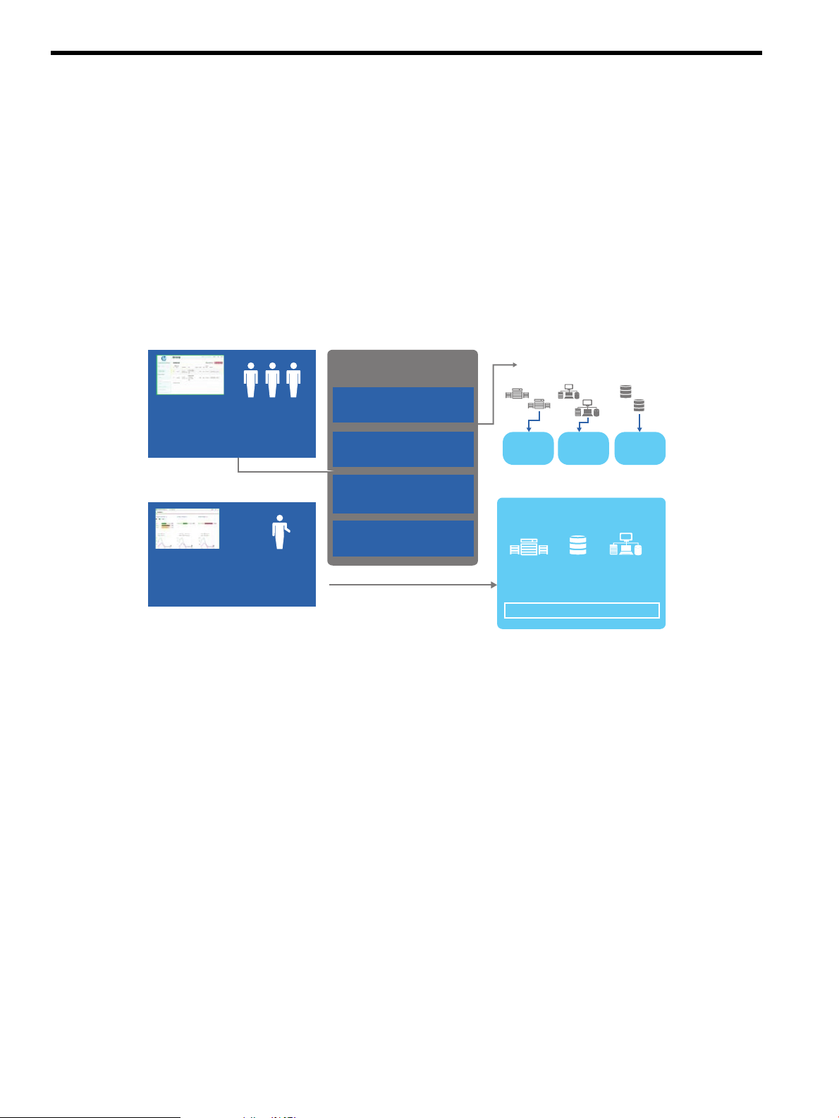
1 Welcome to HP CloudSystem Administrator Guide
Virtual
machines
Networks
and
endpoints
Ephemeral
volumes
Compute
services
Network
services
Storage
services
Servers
HP Converged Infrastructure
Consumers
• Browse, request & manage
virtualized services
• Simple self-service portal
Administrator
• Manage resources and access
• Provision VM Hosts
Identity (Keystone)
users, projects, regions,...
Compute (Nova)
images, instances,
security groups, ...
Network (Neutron)
provider and private tenant
networks, endpoints, routing
Volumes (Cinder)
block storage for VMs
Resources
OpenStack
service offerings
Storage Networking
HP CloudSystem works in converged infrastructure environments and provides a software-defined
approach to managing the cloud. CloudSystem consists of two offerings:
• HP CloudSystem Foundation is based on the HP Cloud OS distribution of OpenStack Cloud
Software. It integrates hardware and software to deliver core Infrastructure as a Service (IaaS)
provisioning and lifecycle management of compute, network and storage resources. You can
manage CloudSystem Foundation from an administrative console, self-service portal, CLIs,
and OpenStack APIs. It provides an appliance-based deployment console to simplify installation
and maintenance, and an embedded version of HP Operations Orchestration (OO) for
automating administrative processes. See CloudSystem Foundation components (page 18) for
more information.
Figure 1 CloudSystem Foundation
• HP CloudSystem Enterprise expands on CloudSystem Foundation to integrate servers, storage,
networking, security, and management to automate the lifecycle for hybrid service delivery.
Template architects can use Enterprise to create infrastructure templates and offer them as
services in a Marketplace Portal. Users select services from a catalog and manage their
subscriptions. When a service is requested, Enterprise automatically provisions the servers,
12 Welcome to HP CloudSystem Administrator Guide
Page 13
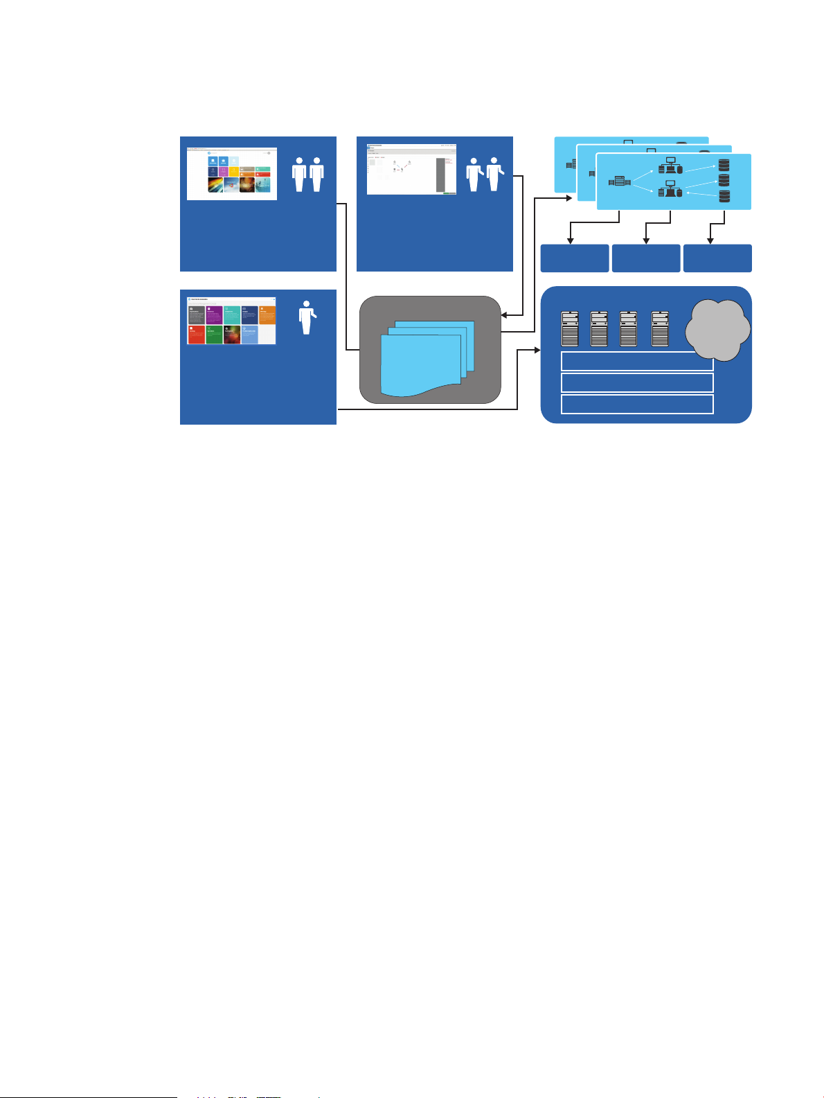
storage, and networking. Enterprise also includes an enhanced set of Operations Orchestration
Consumers
• Browse request & manage
virtualized services
Complex service
template
HP Servers
HP Storage
HP Networking
Resources
Compute
services
Network
services
Storage
services
Figure 2 CloudSystem Enterprise
Design, provision, and manage complex services with HP CloudSystem Enterprise
Administrator
• Manage catalog, subscriptions
and providers
Service Catalog
Public
cloud
services
Architects
• Design and publish
infrastructure and
applications services
• Topology and service
design tools
workflows. See CloudSystem Enterprise components (page 20) for more information.
Figure 2 CloudSystem Enterprise
Features
Features in CloudSystem allow you to:
• Easily install and upgrade CloudSystem, which is a set of virtual machine appliances connected
by multiple networks.
See CloudSystem Foundation components (page 18) and Monitor resource use and allocation
in CloudSystem Console (page 112).
• Manage the lifecycle of your infrastructure, including monitoring its health, using an
administrator user interface that simplifies adding and managing cloud services.
See Monitor resource use and allocation in CloudSystem Console (page 112) and About the
Console Dashboard (page 112).
• Create and activate compute nodes, which have software installed and configured that enables
the compute node to be added to the cloud.
See Compute node creation (page 96) and Compute node management (page 103).
• Configure provider networks, which allow you to connect pre-existing physical networks to
the cloud, and private networks, which allow groups of users to share private resources
exclusively inside their virtual data center or cloud.
See Network configuration (page 73).
• Configure virtual server storage to connect 3PAR storage systems to compute nodes.
See Storage configuration (page 89).
• Create, upload, and manage operating system images. A created image is a snapshot of an
active instance. You can also track which images are in use and on which virtual machines.
See Image management (page 84).
Features 13
Page 14

• Define and configure virtual machines. The number of CPUs and amount of memory to assign
to a virtual machine is designated by selecting the flavor (instance type) to associate with a
virtual machine.
See Virtual machine configuration for compute services (page 108).
• Deploy virtual machine instances with VLAN networks and HP 3PAR virtual machine block
storage using the CloudSystem Portal.
See Provision a cloud in Foundation (page 117).
• Use HP Operations Orchestration workflows to automate operational tasks and processes.
See CloudSystem Foundation components (page 18).
• Install CloudSystem Enterprise. CloudSystem Foundation uses OpenStack technology to provision
and manage cloud services. CloudSystem Enterprise uses CloudSystem Foundation for appliance
management and provides added value through the user interface, capacity planning/analytics,
high availability, disaster recovery, and more.
See About CloudSystem Enterprise (page 124).
• For high availability, use the features of VMware vCenter Server when the cloud is deployed
on ESX clusters. For KVM, a CloudSystem white paper describes setting up an HA environment
on the management cluster in which CloudSystem runs.
• Use OpenStack API technology for portability and developer community access.
• Issue OpenStack commands for supported operations using a Windows or Linux client.
14 Welcome to HP CloudSystem Administrator Guide
Page 15

2 Concepts and architecture
CloudSystem provides you with the flexibility of virtualized compute resources, networks, and
storage. With CloudSystem, you configure, manage, and deploy infrastructure services into a
cloud environment for access by your end users.
How it works
Figure 3 illustrates the relationship between CloudSystem Foundation, the Foundation virtual
appliances, CloudSystem Enterprise, and the underlying network infrastructure.
The CloudSystem Foundation base appliance includes a management console GUI and a web-based,
end-user portal that is built on OpenStack Horizon functionality. The base appliance includes the
data store for Glance images that can be used to build the compute virtual machines. The installation
of CloudSystem Foundation also includes the SDN appliance, the network node appliances, and
a vCenter Server proxy appliance.
From within the CloudSystem Console, you can install the Enterprise piece of CloudSystem. Enterprise
provides significant manageability and design tool extensions and cloud-bursting to multiple
providers through the HP CSA Cloud Service Management Console. Access to these services is
provided to end users through the Marketplace Portal. Once you install the Enterprise software,
you can move between Foundation and Enterprise user interfaces to manage, provision, and deploy
cloud services.
How it works 15
Page 16
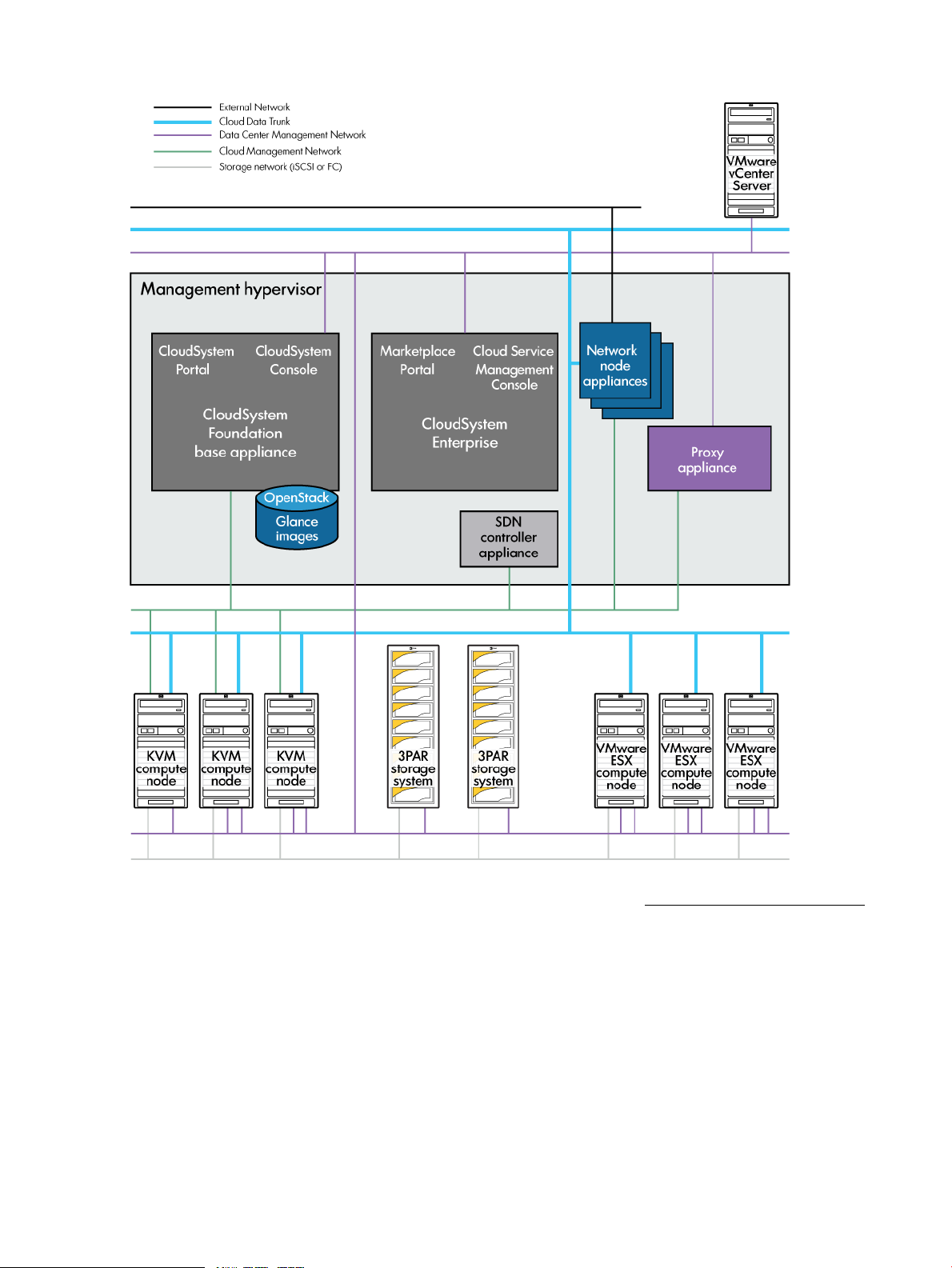
Figure 3 CloudSystem appliances and network infrastructure
See the HP CloudSystem Installation and Configuration Guide at the Enterprise Information Library
for an expanded discussion of network architecture and initial network configuration.
Associated appliances
The following appliances are automatically created after the Cloud Networking settings are saved.
For more information, see Networks in CloudSystem Foundation (page 19).
Software Defined Networking (SDN)
appliance
Network node appliances Manage network services, such as DHCP and L3 (routing)
16 Concepts and architecture
Manages the network infrastructure for the CloudSystem.
services, for provisioned virtual machines and provisioned
virtual networks. Three network node appliances are created
when the Cloud Networking settings are saved.
Page 17

Storage
The following appliance is automatically created after an ESX cluster is imported. (No proxy
appliances are started in a KVM-only environment.)
Proxy appliance Acts as a communication mechanism between OpenStack technology
and VMware vCenter Server, and runs the OpenStack agents for up to
twelve clusters for each vCenter Server. Additional appliances are
automatically created when the number of new clusters added to the cloud
are reached. New proxy appliances are created with the first, 13th, and
25th cluster additions.
CloudSystem works with HP 3PAR StoreServ Storage, a cluster-based storage architecture that
incorporates data management and fault tolerance technologies that can meet the storage needs
of smaller sites and can be scaled for global organizations.
3PAR storage is required to create block storage for VM guests.
Storage for manually provisioned hypervisor hosts is more flexible, and can include local disks.
Virtual server storage
Virtual server storage connects the 3PAR storage system to virtual machine instances. Options
include:
• Fibre Channel Storage Area Network (FC SAN), which provides block-level storage that can
be accessed by the applications running on any networked servers
• Direct-Attach Fibre Channel Storage, a single-layer Fibre Channel storage network that
eliminates SAN switches and HBAs (host bus adapters)
• iSCSI, which is block-level storage that uses traditional Ethernet network components for
connectivity
Physical servers
Servers running an ESX cluster or a KVM hypervisor can be used as a management cluster, a
management hypervisor, or as compute clusters or nodes.
Management cluster or hypervisor Clustered or standalone hypervisors that host the virtual
machine appliances that comprise the CloudSystem solution.
There are three possible configurations:
• An ESX management cluster that hosts the virtual
machines running CloudSystem and its integrated tools.
• A standalone ESX management hypervisor that hosts
the virtual machines running CloudSystem and its
integrated tools.
See also Integrated tool connectivity and configuration
(page 81).
• A KVM management hypervisor that hosts the virtual
machines running CloudSystem software.
Compute nodes ESX clusters and KVM hosts that provide the pool of
User authentication
You can choose one of two methods of user authentication. If you use local logins, CloudSystem
provides local authentication for users authorized to access CloudSystem. The Infrastructure
administrator enters user data, which is saved in the appliance database. When anyone tries to
hypervisor resources used to provision virtual machine
instances.
How it works 17
Page 18

access the CloudSystem Console or Portal, the login information entered is checked against the
user attributes stored in the database.
Alternatively, you can use an external authentication directory service (also called an enterprise
directory) to provide a single sign-on for groups of users instead of maintaining individual local
login accounts. Examples of an authentication directory service include Microsoft Windows Active
Directory or OpenLDAP (LDAP - Lightweight Directory Access Protocol).
For more information, see Security in CloudSystem (page 22) and Manage users and groups
(page 52).
OpenStack technology
CloudSystem software leverages the capabilities of multiple OpenStack technologies. Because of
this underlying functionality, you can use OpenStack CLI and API to configure compute resources,
and provision and deploy these resources to a cloud.
Table 1 OpenStack clients used in CloudSystem
CapabilityServiceClient
Block storage managementCinder
Compute resource managementNova
For additional information on installing and using the OpenStack CLI with CloudSystem software,
see the “Command line interfaces” appendix in the HP CloudSystem 8.0 Installation and
Configuration Guide at Enterprise Information Library.
The CloudSystem Portal is based on the Openstack Horizon client. Not all OpenStack features are
supported in this version of CloudSystem. For information on limitations, see Limitations on support
for OpenStack CLI commands (page 204) and Limitations on support for OpenStack functionality
in the CloudSystem Portal (page 210).
CloudSystem Foundation at a glance
HP CloudSystem allows you to prepare private cloud resources and deploy virtual machine instances
into this cloud. In CloudSystem Foundation, you use CloudSystem Console to configure cloud
resources for deployment. This includes creating images, establishing shared and private networks,
and configuring block storage. End users use the CloudSystem Portal to provision and manage
VMs, storage, and networks. This work includes managing virtual machine security, attaching
volumes, and launching virtual machine instances.
When you provision new subscriptions from CloudSystem Enterprise, new virtual machines, block
storage volumes, and networks are provisioned in CloudSystem Foundation. These resources are
visible in the CloudSystem Portal. If you modify them from the CloudSystem Portal, the changes
will not be reflected in the Enterprise Marketplace Portal.
Create, configure, and assign storage volumes and
volume types
Create, configure and store imagesImage managementGlance
Create users and manage user roles and credentialsIdentity managementKeystone
Configure Private (and External) networksNetwork managementNeutron
Manage virtual machine instances, flavors, and
images and deploy instances to a cloud
CloudSystem Foundation components
CloudSystem Foundation is the platform that you use to manage both Foundation and Enterprise
appliances. Foundation includes the following components, which run on virtual machine appliances
on the management cluster or hypervisor.
CloudSystem Console Web-based user interface for administrative tasks, including
18 Concepts and architecture
managing and monitoring the cloud and releasing resources
Page 19

back to the cloud. From the console, you can activate
compute nodes, configure networks and storage, and
perform maintenance tasks on the Foundation and Enterprise
appliances.
CloudSystem Portal Web-based interface for creating, launching, and managing
virtual machine instances. The portal can be accessed by
appending /portal to the Foundation appliance URL (for
example, https://192.0.2.2/portal).
HP Operations Orchestration Operations Orchestration Central automates operational
tasks and processes using a set of predefined workflows.
OO Central is packaged with the Foundation appliance
and is launched from the Integrated Tools screen in the
CloudSystem Console. Enterprise integrates with OO Central
to support pre- and post-server group provisioning.
Operations Orchestration Studio is an optional tool for
customizing workflows, which is installed separately. The
OO Studio installation files are included with the
CloudSystem installation tar files. See the HP CloudSystem
Installation and Configuration Guide on the Enterprise
Information Library for more information.
Command line interface csadmin provides command line access for storage system
administrative tasks, private network VLAN management
tasks, appliance management tasks and console user
management tasks.
csstart deploys and configures the Foundation base
appliance on the management cluster or hypervisor. For a
more friendly user experience, launch the csstart GUI; or
you can run csstart from the command line.
Networks in CloudSystem Foundation
CloudSystem Foundation is built on OpenStack Networking technology. The underlying network
infrastructure is managed by a Software Defined Networking (SDN) appliance. Multiple network
node appliances manage network services, such as DHCP and routing. A vCenter proxy appliance
runs the OpenStack agents for use. All of these virtual appliances to support networking are
automatically created when CloudSystem Foundation is configured. You can use the CLI to access
and manage these appliances.
CloudSystem Foundation uses three types of networks:
• Private networks are restricted and can be accessed only by virtual machine instances assigned
to the network. See About Private Networks (page 76).
• Provider networksisc.prov.ntwks.name; are shared networks in the data center on which users
can provision any number of virtual machine instances. See About Provider Networks
(page 74).
• The External Network allows you to route virtual machine instances on Private networks out
from the CloudSystem private cloud to the data center, the corporate intranet, or the Internet..
See About the External Network (page 77).
See also How it works (page 15).
CloudSystem Foundation at a glance 19
Page 20

Network tasks and user roles
The following table lists CloudSystem network tasks according to user roles and the interfaces used
to perform them.
Additional informationInterfaceUser RoleTask
and VLAN ranges that can
be assigned to Private
Networks
Network configuration
using supported APIs
instances
networks
either dedicated static IPs or
DHCP
Private networks from
outside of the cloud using
floating IP addresses
CloudSystem ConsoleInfrastructure administratorCreate pools of VLAN IDs
CloudSystem ConsoleInfrastructure administratorCreate Provider networks
CloudSystem PortalInfrastructure administratorComplete the External
Infrastructure administratorCustomize network offerings
Foundation base appliance
command line
CloudSystem PortalCloud userCreate routers to connect
CloudSystem PortalCloud userAccess instances that are on
About Private Networks
(page 76)
About Provider Networks
(page 74)
About the External Network
(page 77)
OpenStack Networking API
v2.0 Reference
OpenStack End User GuideCloudSystem PortalCloud userAttach Private networks to
OpenStack End User Guide
and Creating an External
Network router (page 79)
OpenStack End User GuideCloudSystem PortalCloud administratorManage IP addresses using
OpenStack End User Guide
and Assigning floating IP
addresses to instances
(page 79)
CloudSystem Enterprise at a glance
To install CloudSystem Enterprise, select the Enterprise screen on the main menu in the CloudSystem
Console and click Install CloudSystem Enterprise. After installation, the Enterprise screen in the
CloudSystem Console provides links to HP Cloud Service Automation and the Marketplace Portal.
You will continue to use the Foundation platform to perform appliance management tasks after
Enterprise is installed.
CloudSystem Enterprise components
Enterprise includes the following components:
HP CSA Cloud Service Management
Console
Marketplace Portal The Marketplace Portal provides a customer interface for
HP Cloud Service Automation orchestrates the deployment
of compute and infrastructure resources and complex
multi-tier application architectures. HP CSA and its user
interface, the Cloud Service Management Console,
integrates and leverages the strengths of several HP data
center management and automation products, adding
resource management, service offering design, and a
customer portal to create a comprehensive service
automation solution.
requesting new cloud services and for monitoring and
managing existing services, with subscription pricing to meet
your business requirements.
20 Concepts and architecture
Page 21

Topology Designer and Sequential
Designer
The HP CSA graphical service design and content portability
tools simplify developing, leveraging, and sharing an array
of service offerings that can be tailored to your end users’
needs.
You can use two different designers to design new cloud
services with reusable service design templates.
• Use Topology Designer to create infrastructure service
designs.
• Use Sequential Designer to create more complex
application service designs.
The designs created through both designers appear as
service offerings that Marketplace Portal users can select
and provision.
CloudSystem Enterprise at a glance 21
Page 22

3 Security in CloudSystem
CloudSystem security depends in part on the security level that you chose when you installed
CloudSystem Foundation and on your work practices. This chapter describes security concepts to
consider when working with browsers, certificates, and networks for secure communication and
transfer of data among the appliances, networks, and computes nodes in a CloudSystem virtualized
data center.
For additional information, see Manage security (page 67) and the HP CloudSystem Installation
and Configuration Guide on the Enterprise Information Library.
Best practices for maintaining a secure appliance
Most security policies and practices used in a traditional environment apply in a virtualized
environment. However, in a virtualized environment, these policies might require modifications
and additions.
22 Security in CloudSystem
Page 23

The following table comprises a partial list of security best practices that HP recommends in both
physical and virtual environments. Differing security policies and implementation practices make
it difficult to provide a complete and definitive list.
Best PracticeTopic
Accounts
Certificates
• Limit the number of local accounts. Integrate the appliance with an enterprise directory solution
such as Microsoft Active Directory or OpenLDAP.
• Use certificates signed by a trusted certificate authority (CA), if possible.
CloudSystem uses certificates to authenticate and establish trust relationships. One of the most
common uses of certificates is when a connection from a web browser to a web server is
established. The machine level authentication is carried out as part of the HTTPS protocol, using
SSL. Certificates can also be used to authenticate devices when setting up a communication
channel.
The appliance supports self-signed certificates and certificates issued by a CA.
The appliance is initially configured with self-signed certificates for the web server, database,
and message broker software. The browser will display a warning when browsing to the
appliance using self-signed certificates.
HP advises customers to examine their security needs (that is, to perform a risk assessment) and
consider the use of certificates signed by a trusted CA. For the highest level of security, HP
recommends that you use certificates signed by a trusted certificate authority:
◦ Ideally, you should use your company's existing CA and import their trusted certificates. The
trusted root CA certificate should be deployed to user’s browsers that will contact systems
and devices that will need to perform certificate validation
◦ If your company does not have its own certificate authority, then consider using an external
CA. There are numerous third-party companies that provide trusted certificates. You will need
to work with the external CA to have certificates generated for specific devices and systems
and then import these trusted certificates into the components that use them.
As the Infrastructure administrator, you can generate a CSR (certificate signing request) and,
upon receipt, upload the certificate to the appliance web server. This ensures the integrity and
authenticity of your HTTPS connection to the appliance. Certificates can also be uploaded for
the database and message broker.
Network
Nonessential
services
Passwords
Roles
Service
Management
• Do not connect management systems (for example, the appliance, the iLO card, and Onboard
Administrator) directly to the Internet.
If you require access to the Internet, use a corporate VPN (virtual private network) that provides
firewall protection.
• The appliance is preconfigured so that nonessential services are removed or disabled in its
management environment. Ensure that you continue to minimize services when you configure
host systems, management systems, network devices (including network ports not in use) to
significantly reduce the number of ways your environment could be attacked.
• For local accounts on the appliance, change the passwords periodically according to your
password policies.
• Password contains between 8 and 40 characters
• The following special characters are not allowed:
< > ; , " ' & / \ | + =
• Clearly define and use administrative roles and responsibilities; for example, the Infrastructure
administrator performs most administrative tasks.
• Consider using the practices and procedures, such as those defined by the Information Technology
Infrastructure Library (ITIL). For more information, see the following website:
http://www.itil-officialsite.com/home/home.aspx
Best practices for maintaining a secure appliance 23
Page 24

Best PracticeTopic
Updates
Virtual
Environment
• Ensure that a process is in place to determine if software and firmware updates are available,
and to install updates for all components in your environment on a regular basis.
• Most security policies and practices used in a traditional environment apply in a virtualized
environment. However, in a virtualized environment, these policies might require modifications
and additions.
• Educate administrators about changes to their roles and responsibilities in a virtual environment.
• Restrict access to the appliance console to authorized users. For more information, see Restricting
console access (page 24).
• If you use an Intrusion Detection System (IDS) solution in your environment, ensure that the solution
has visibility into network traffic in the virtual switch.
• Maintain a zone of trust, for example, a DMZ (demilitarized zone) that is separate from production
machines.
• Ensure proper access controls on Fibre Channel devices.
• Use LUN masking on both storage and compute hosts.
• Ensure that LUNs are defined in the host configuration, instead of being discovered.
• Use hard zoning (which restricts communication across a fabric) based on port WWNs
(Worldwide Names), if possible.
• Ensure that communication with the WWNs is enforced at the switch-port level.
Enabling or disabling authorized services access
When you first start up the appliance, you can choose to enable or disable access by on-site
authorized support representatives. By default, on-site authorized support representatives are
allowed to access your system through the appliance console and diagnose issues that you have
reported.
Support access is a root-level shell, which enables the on-site authorized support representative to
debug any problems on the appliance and obtain a one-time password using a challenge/response
mechanism similar to the one for a password reset.
Any time after the initial configuration of the appliance, you can enable or disable services access
through the UI by selecting Actions→Edit services access on the Settings window.
You can also use an appliance/settings REST API to enable or disable services access.
NOTE: HP recommends that you enable access. Otherwise, the authorized support representative
might be unable to access the appliance to correct a problem.
Restricting console access
For the virtual appliance, you can restrict console access through secure management practices
of the hypervisor itself.
For VMware vSphere, this information is available from the VMware website:
http://www.vmware.com
In particular, search for topics related to vSphere's Console Interaction privilege and best practices
for managing VMware's roles and permissions.
Best practices for browser use
• Enable SSL v3 and TLS.
SSL v2 is considered insecure and should not be enabled in the browser unless there is a
specific need for it.
• Enable cookies to store the authenticated user’s session ID.
24 Security in CloudSystem
Page 25

• Always log out before closing the browser.
In the browser, a memory-based cookie stores the authenticated user’s session ID.
Memory-based cookies are deleted when you close the browser. When you log out, the session
on the appliance is invalidated.
• Avoid clicking links outside the appliance UI.
While logged in to the appliance, avoid clicking links in email or instant messages. The links
might be malicious and take advantage of your login session.
• Use separate browsers for appliance and non-appliance use.
Do not use the same browser instance (for example, separate tabs in the same browser) to
browse to other websites.
Managing certificates from a browser
A certificate authenticates the appliance over SSL. The certificate contains a public key, and the
appliance maintains the corresponding private key, which is uniquely tied to the public key.
NOTE: This section discusses certificate management from the perspective of the browser. For
information on how a non-browser client (such as cURL) uses the certificate, see the documentation
for that client.
The certificate also contains the name of the appliance, which the SSL client uses to identify the
appliance.
The certificate has the following boxes:
• Common Name (CN)
This name is required. By default it contains the fully qualified host name of the appliance.
• Alternative Name
The name is optional, but HP recommends supplying it because it supports multiple names
(including IP addresses) to minimize name-mismatch warnings from the browser.
By default, this name is populated with the fully qualified host name (if DNS is in use), a short
host name, and the appliance IP address.
NOTE: If you enter Alternative Names, one of them must be your entry for the Common
Name.
Self-signed certificate
The default certificate generated by the appliance is self-signed; it is not issued by a trusted certificate
authority.
By default, browsers do not trust self-signed certificates because they lack prior knowledge of them.
The browser displays a warning dialog box; you can use it to examine the content of the self-signed
certificate before accepting it.
Protecting credentials
Local user account passwords are stored using a salted hash; that is, they are combined with a
random string, and then the combined value is stored as a hash. A hash is a one-way algorithm
that maps a string to a unique value so that the original string cannot be retrieved from the hash.
Passwords are masked in the browser. When transmitted between appliance and the browser over
the network, passwords are protected by SSL.
Local user account passwords must be a minimum of eight characters, with at least one uppercase
character. The appliance does not enforce additional password complexity rules. Password strength
Managing certificates from a browser 25
Page 26

and expiration are dictated by the site security policy. If you integrate an external authentication
directory service (also known as an enterprise directory) with the appliance, the directory service
enforces password strength and expiration.
26 Security in CloudSystem
Page 27

4 Installation
A successful install and configuration of CloudSystem software depends on the preparation done
beforehand. See the HP CloudSystem Installation and Configuration Guide on the Enterprise
Information Library for the following information.
• Supported hardware and software configurations
• Preparations necessary prior to installing CloudSystem
• Network configuration details
• HP Operations Orchestration configuration
• Installing CloudSystem Enterprise
• Troubleshooting installation
• csstart command reference
• Configuring additional virtualization providers to work with CloudSystem Enterprise
27
Page 28
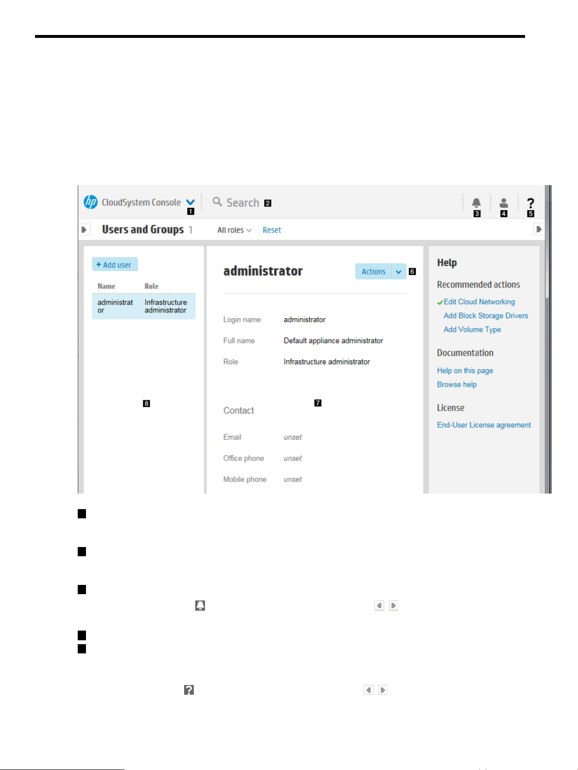
5 Navigating the CloudSystem Console GUI
This chapter provides you with an overview of the GUI functions in the CloudSystem Console. More
information about using these features is located in the CloudSystem Console Help.
About the graphical user interface
The image shown below illustrates important areas in the CloudSystem Console graphical user
interface.
Figure 4 Screen components
1
Main menu: Access the primary resource management areas of the appliance for compute,
networking, and storage resources, and for appliance administration. (To see the main menu,
click in the gray area labeled CloudSystem Console.)
2
Search: Enter a search term. The Scope option allows you to restrict your search to the resource
you are on, or widen the search to all resources managed by the CloudSystem Console. (To
see the Scope selector, click on or near the word “Search”.)
3
Activity sidebar: View alerts and notifications generated by the appliance.
Click the Activity icon , then click the left or right pin icons to expand or collapse this
sidebar.
4
Session control: View the status of your login, or log out of the appliance.
5
Help sidebar: View links to online help and to recommended actions. Recommended actions
include tasks needed to configure the appliance or to prepare resources for provisioning to
a cloud.
Click the Help icon , then click the left or right pin icons to expand or collapse this
sidebar.
28 Navigating the CloudSystem Console GUI
Page 29
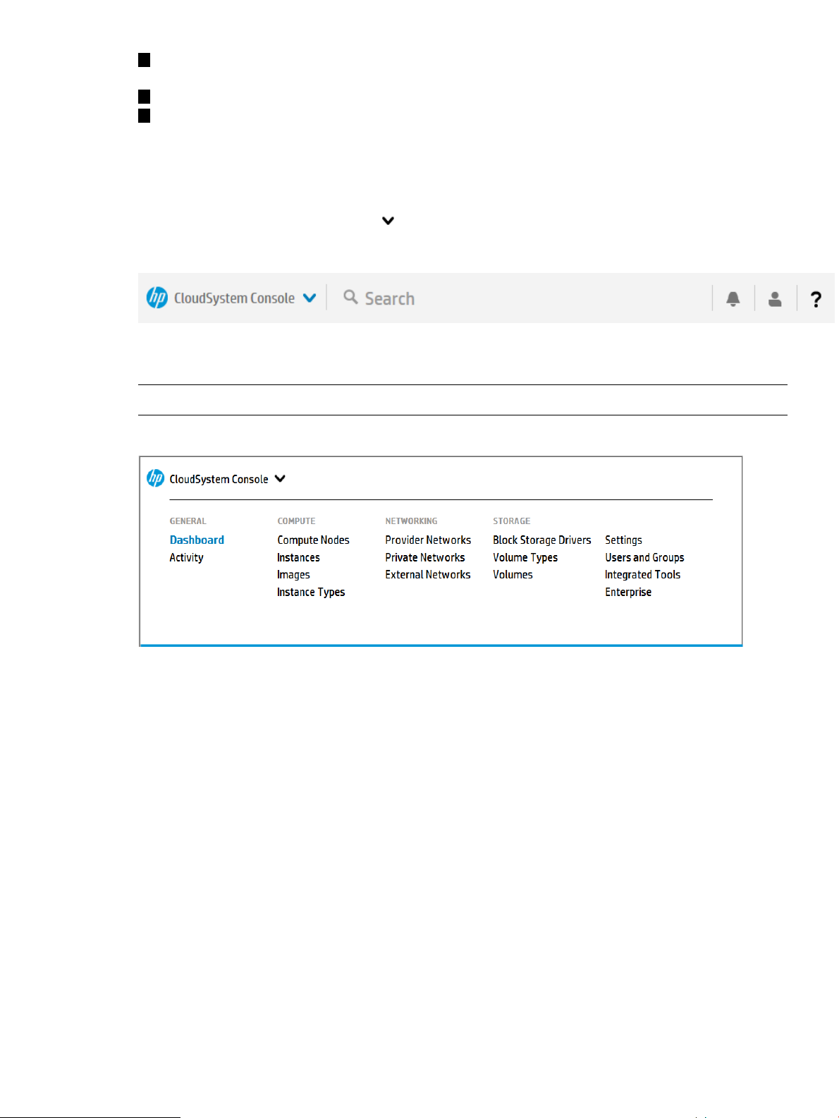
6
Actions menu: Access the available actions that you can perform on a resource. Actions menus
contain only tasks that can be performed on a specific resource.
7
Details pane: View the details for the resource area you have open.
8
Master pane: Manage the display of information in the Details pane for each specific resource.
You can use filters and sorting to control the display of information.
Use the banner and main menu to navigate
Use the main menu to navigate through the resources and actions that the appliance provides.
To expand the main menu, click the in the banner at the top of the screen.
Figure 5 Main menu and top of page banner
The main menu provides access to resources and actions. The following figure shows the expanded
menu.
NOTE: Your ability to view a resource or perform an action depends on your role.
Figure 6 Main menu
About Activity
The Activity overview screen lists alerts and other notifications about activities occurring in your
cloud environment. You can filter, sort, and expand areas of the screen to refine how information
is displayed. Links within activity details enable you to view additional information about specific
resources listed.
Activity Screen components
You can use the screen areas shown below to monitor and interpret Activity data.
Use the banner and main menu to navigate 29
Page 30
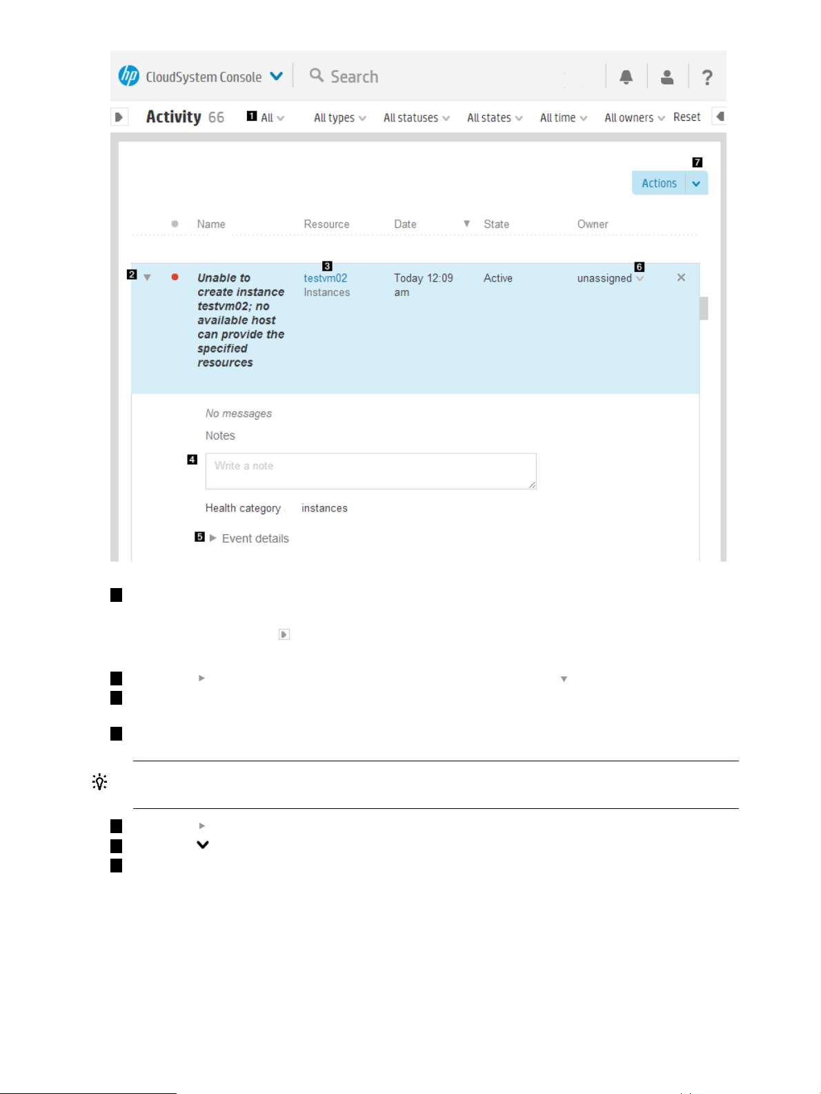
1
The default Activity view shows all active notifications. Use the filters and date range selectors
on the Filters menu bar to filter all stored notifications.
You can also click the icon to expand (or collapse) the filter banner, which contains the
same selection choices in a vertical presentation.
2
Click the icon to expand the view of a notification, or click the icon to collapse the view.
3
Click the link to view details about the resource associated with this notification. If multiple
events have sent the same notification, a count is given.
4
Type in the note box to add instructions or other information to this notification.
TIP: You can click and drag the lower right corner of the note box to expand the box for
better viewing or easier editing.
5
Click the icon to view more details about this notification.
6
Click the icon and select from the list to assign (or reassign) an Owner for this notification.
7
Use the Actions menu to assign, clear, or restore selected notifications.
About alerts
The appliance uses alert messages to report issues with the resources it manages. The resources
generate alerts to notify you that some meaningful event occurred and that an action might be
required.
An event is a single, low-level problem or change that occurred on a resource. Usually, events are
detected by an agent running either on the resource or on the appliance.
30 Navigating the CloudSystem Console GUI
Page 31

Each alert includes the following information about the event it reports: severity, state, description,
and urgency. You can clear alerts, assign owners to alerts, and add notes to alerts.
While alerts have an active or locked state, they contribute to a resource’s overall displayed status.
After you change their state to Cleared, they no longer affect the displayed status.
IMPORTANT:
The appliance keeps a running count of incoming alerts. At intervals of 500 alert messages, the
appliance determines if the number of alerts has reached 75,000. When it does, an auto-cleanup
occurs, which deletes alert messages until the total number is fewer than 74,200. When the
auto-cleanup runs, it first removes the oldest cleared alerts. Then it deletes the oldest alerts by
severity.
About tasks
All user-initiated tasks are reported as activities. User-initiated tasks are created when a user adds,
creates, removes, updates, or deletes resources.
The Activity screen provides a valuable source of monitoring and troubleshooting information that
you can use to resolve an issue. You can determine the type of task performed, whether the task
was completed, when the task was completed, and who initiated the task.
IMPORTANT: The appliance maintains a task database that holds information for approximately
six months or 50,000 tasks. If the task database exceeds 50,000 tasks within the six-month period,
the oldest blocks of 500 tasks are deleted until the count is fewer than 50,000. Tasks older than
six months are removed from the database.
The task database and the database that stores alerts are separate.
About the Activity sidebar
The Activity sidebar shows tasks initiated during the current session. The most recent task is displayed
first.
Task notifications provide information (including in-progress, error, and completion messages)
about tasks that were launched.
The Activity sidebar differs from the Activity screen because it displays only recent activity. The
Activity screen, in contrast, displays all activities and allows you to list, sort, and filter them. For
more information, see About Activity (page 29).
Click an activity to show more details.
Activity states
DescriptionStateActivity
The alert has not been cleared or resolved.ActiveAlert
A resource’s active alerts are considered in the resource’s overall health status.
Active alerts contribute to the alert count summary.
An Active alert that was set (locked) by an internal resource manager.Locked
You cannot manually clear a Locked alert. Examine the corrective action
associated with an alert to determine how to fix the problem. After the problem
is fixed, the resource manager moves the alert to the Active state. At that
time, you can clear the alert.
A resource’s locked alerts contribute to its overall status.
Cleared
The alert was addressed, noted, or resolved. You clear an activity when it no
longer needs to be tracked.
The appliance clears certain activities automatically.
About Activity 31
Page 32

DescriptionStateActivity
Cleared activities do not affect the resource’s health status and they are not
counted in the displayed summaries.
The task started and ran to completion.CompletedTask
The task has started and is running, but has not yet completed.Running
The task has not yet run.Pending
Activity statuses
Warning
Interrupted
Warning
DescriptionStatus
A critical alert message was received, or a task failed or was interrupted.Critical
Investigate Critical status activities immediately.
An event occurred that might require your attention. A warning can mean that something is
not correct within the appliance and it needs your attention.
Investigate Warning status activities immediately.
For an alert, OK indicates normal behavior or information from a resource.OK
For a task, OK indicates that it completed successfully.
The task ran, but was interrupted. For example, it could be waiting for a
resource
A task failed or generated a Critical alert.Error
Investigate Error states immediately.
A task was gracefully shut down or cancelled.Terminated
An event occurred that might require your attention. A warning can mean that
something is not correct within the appliance.
Investigate Warning states immediately.
Icon descriptions
HP CloudSystem uses icons as user controls and to show the current status of resources and activities.
Status and severity icons
The status of the alert or task is unknown.Unknown
The status of a task that is set to run at a later time is Unknown.
A task was prevented from continuing or completing.Disabled
CriticalError
WarningWarning
ExplanationActivity NotificationResourceSmall iconLarge icon
Failed/Interrupted. Investigate
immediately.
See also Troubleshooting
reference (page 138).
Component is active but
issues exist that can impact
performance. Investigate and
determine what action to
take.
32 Navigating the CloudSystem Console GUI
Page 33

ExplanationActivity NotificationResourceSmall iconLarge icon
User control icons
menu
View details
InformationalOK
InformationalUnknown
An In progress rotating icon indicates that a change is being applied or a task is running.
This icon can appear in combination with any of the resource states; for example:
ActionNameIcon
Expands a menu to show all optionsExpand
Identifies a title that has additional information. Clicking the title changes the view to
display details.
Expands a collapsed list itemExpand
Component is active. No
action needed.
Component is not known to
the cloud and is not in an
active state within the cloud.
Determine if intervention is
needed.
remove
Search
Collapses an expanded list itemCollapse
Enables editingEdit
Deletes the current entryDelete or
Searches for the text you enter in the Search box. This is especially useful for finding types
of resources or specific resources by name
The left pin collapses or expands the Filters pane.Pin
The right pin docks the Activity and Help sidebars.
Determines whether items are displayed in ascending or descending orderSort
Icon descriptions 33
Page 34

Informational icons
control
DescriptionNameIcon
Provides information about recent task activities for operations, user actions, and resourcesActivity
Session
control
Help control
Browser requirements
The appliance has specific browser requirements that can affect its use. The following browsers
are supported:
• Microsoft Internet Explorer: Version 9 and Version 10
• Mozilla Firefox: ESR Version 24, Personal edition (latest version)
• Google Chrome Version 31
Displays your login name and the duration of your current session. Also provides a link
you can use to log out of the appliance.
• When this icon is at the top of a dialog box, you can click it to open context-sensitive
help for that topic in another window or tab.
• In the banner, this icon expands or collapses the Help sidebar, where you can browse
the help documentation or find help on the screen currently displayed. The help sidebar
provides the following:
◦ A Help on this page hyperlink to access context-sensitive help for the current screen
◦ A Browse help hyperlink to access the entire help system
◦ Links that you can use to display the EULA and the Written Offer.
Required browser plug-ins and settings
The following browser settings must be enabled for the software to work correctly:
• JavaScript
• Image loading
• SSL 3.0 or TLS 1.0 security options
• Session cookies
• Adobe Flash plugin version 10 or later
Supported browser features and settings
Screen resolution For optimum performance, the screen size should be at least
1280×1024 pixels for desktop monitors, or 1280×800 for laptop
displays. The minimum supported screen size is 1024×768 pixels.
Close window Browser windows can be closed at any time. Closing the window while
you are logged in automatically ends your session so that another user
cannot connect to it.
NOTE: Closing the browser tab does not end your session.
Copy and paste Almost any text can be selected and copied. However, text that is part
of an image cannot be selected and copied. You can paste into text
entry fields.
34 Navigating the CloudSystem Console GUI
Page 35

Language This version is available in US English, Japanese, and Simplified
Search
Search
Scope Server Profiles Everything
..................................................................................
Search resources
The banner of every screen includes the Smart Search feature, which enables you to find
resource-specific information such as specific instances of resource names, serial numbers, WWNs
(World Wide Names), and IP and MAC addresses.
In general, anything that appears in a resource master pane is searchable.
Smart Search makes locating resources easy, enabling you to inventory or take action on a desired
set of resources.
The default search behavior is to focus on the resource you are currently viewing. But, to broaden
the scope of your search across all resources, you have the option to search Everything, which
searches all resources.
Chinese.
Set your browser language preference to one of these languages. To
ensure that server-generated messages are displayed in the same
language as the browser displays, set the Locale in the Time and
Language section of the Settings: Appliance screen to match the browser
language.
Search all resourcesSearch the current resource
1. Click in the Smart Search box.
2. 2.Enter your search text and press Enter.
The search results are focused in your current location
in the UI.
1. Click in the Smart Search box.
Select Everything.
3. Enter your search text and press Enter.
Some resources might not include the option to choose between the current resource or everything,
in which case the default search is for everything.
When you start typing, search suggestions are provided based on pattern matching and
previously-entered search criteria.
• You can either select a suggestion (the screen displays data containing that selection) or click
Enter.
• If your search term is a resource, then the list of resources in a master pane is filtered to match
your search input.
TIP:
• Enter complete words or names as your search criteria. Partial words or names might not
return the expected results.
• If you enter a multi-word search term, results show matches for all words you enter.
• Enclose a search term in double quotes (”) if the search term contains spaces.
Search resources 35
Page 36

When you find what you are looking for in the search results, which are organized by type, select
the item to navigate to it.
Table 2 Advanced searching and filtering with properties
Search resultsExample of advanced filtering syntax
All hardware that match the model number and name.By model name:
model: "BladeSystem c7000 Enclosure G2"
model: "ProLiant BL460c Gen8"
model: "HP VC 8Gb 20-Port FC Module"
By name or address:
An enclosure with the name enclosure10.name: enclosure10
name: "192.0.2"
name: "mysystem"
A list of virtual machines whose IP addresses begin with
192.0.2.
A list of virtual machines for which the host name is
mysystem.
All resources that are in a critical state.By health status:
For other health status values, see Activity statuses (page 32).status: Critical
36 Navigating the CloudSystem Console GUI
Page 37

6 Support and other resources
IMPORTANT: This product contains a technical feature that will allow an on-site authorized
support representative to access your system, through the system console, to assess problems that
you have reported. This access will be controlled by a password generated by HP that will only
be provided to the authorized support representative. You can disable access at any time while
the system is running.
HP technical support personnel are not granted remote access to the appliance.
Information to collect before contacting HP
Be sure to have the following information available before you contact HP:
• Software product name
• Hardware product model number
• Operating system type and version
• Applicable error message
• Third-party hardware or software
• Technical support registration number (if applicable)
Understanding the audit log
The audit log contains a record of actions performed on the appliance, which you can use for
individual accountability.
You must have Infrastructure administrator privileges to download the audit log.
To download the audit log from the UI, select Settings→Actions→Download audit log. You must
have Infrastructure administrator privileges.
Monitor the audit logs because they are rolled over periodically to prevent them from getting too
large. Download the audit logs periodically to maintain a long-term audit history.
Each user has a unique logging ID per session, enabling you to follow a user’s trail in the audit
log. Some actions are performed by the appliance and might not have a logging ID.
A breakdown of an audit entry follows:
DescriptionToken
The date and time of the eventDate/time
The unique identifier of an internal componentInternal component
ID
The organization ID. Reserved for internal useReserved
The login domain name of the userUser domain
The user nameUser name/ID
The user session ID associated with the messageSession ID
The URI of the task resource associated with the messageTask ID
The client (browser) IP address identifies the client machine that initiated the requestClient host/IP
Information to collect before contacting HP 37
Page 38

DescriptionToken
Result The result of the action, which can be one of the following values:
• SUCCESS
• FAILURE
• SOME_FAILURES
• CANCELED
• KILLED
A description of the action, which can be one of the following values:Action
• •••MODIFY LOGINDEPLOYENABLE
•• ••DISABLEDELETE LOGOUTSTART
••• •DONESAVEACCESS DOWNLOAD_START
••• KILLEDSETUPRUN
• CANCELED• UNSETUP• LIST• ADD
Severity
A description of the severity of the event, which can be one of the following values, listed in
descending order of importance:
• INFO
• NOTICE
• WARNING
• ERROR
• ALERT
• CRITICAL
The resource URI/name associated with the taskResource URI/name
The output message that appears in the audit logMessage
Example 1 Sample audit entries: user login and logout
2013-09-16 14:55:20.706 CST,Authentication,,,administrator,jrWI9ych,,,
SUCCESS,LOGIN,INFO,CREDENTIAL,,Authentication SUCCESS
.
.
.
2013-09-16 14:58:15.201 CST,Authentication,,,MISSING_UID,jrWI9ych,,,
SUCCESS,LOGOUT,INFO,CREDENTIAL,,TERMINATING SESSION
Download audit logs
The audit log shows the security administrator what security-related actions took place on the base
appliance.
You can download log files and other information for your authorized support representative to
use to diagnose and troubleshoot an appliance.
Prerequisites
• Minimum required privileges: Infrastructure administrator
Procedure 1 Downloading audit logs
1. From the Settings screen, select Actions→Download audit logs.
38 Support and other resources
Page 39

2. The appliance generates a compressed file of the audit logs and downloads it to your local
computer.
The compressed file is named following this format:
audit-logs-yyyy_mm_dd-hh_mm_ss
yyyy_mm_dd indicates the date, and hh_mm_ss indicates the time the file was created. The
name of the audit log file is displayed on the screen.
The audit log file is downloaded to the default download folder. If no default download folder
is configured in your browser, you are prompted to specify a destination file.
Create a support dump file
NOTE: This procedure creates a support dump for the base appliance only.
Some error messages recommend that you create a support dump of the appliance and send it to
an authorized support representative for analysis. The support dump process performs the following
functions:
• Deletes any existing support dump file
• Gathers logs and other information required for debugging
• Creates a compressed file with a name in the following format:
hostname-CI-timestamp.sdmp
Unless you specify otherwise, all data in the support dump file is encrypted so that only an
authorized support representative can access it.
You can choose not to encrypt the support dump file if you have an onsite, authorized support
representative or if your environment prohibits outside connections. You can also validate the
contents of the support dump file and verify that it does not contain sensitive data such as passwords.
The support dump file is a gzip of a tar file. Renaming your support dump to have a .tar.gz
or .tgz extension can make it easier to examine the contents.
IMPORTANT: If the appliance is in an error state, you can still create an encrypted support dump
file without logging in or other authentication.
The support dump file contains the following:
• Operating system logs
• Product logs
• The results of certain operating system and product-related commands
For issues regarding virtual machine instance creation and deployment, gather the following files
created on the compute nodes:
• /var/log/nova/*
• /var/log/isc/*
• /var/log/libvirt/*
• /etc/libvirt/*
Items logged in the support dump file are recorded according to UTC time.
Prerequisites
• Minimum required privileges: Infrastructure administrator
Procedure 2 Creating a support dump file
1. From the main menu, select Settings→Actions→Create support dump.
Information to collect before contacting HP 39
Page 40

2. Choose whether or not to encrypt the support dump file:
a. To encrypt the support dump file, confirm that the Enable support dump encryption check
box is selected.
b. To turn off encryption, clear the Enable support dump encryption check box.
3. Click Yes, create.
You can continue doing other tasks while the support dump file is created.
4. The support dump file is downloaded when this task is completed. If your browser settings
specify a default download folder, the support dump file is placed in that folder. Otherwise,
you are prompted to indicate where to download the file.
5. Contact your authorized support representative for instructions on how to transfer the support
dump file to HP.
For information on contacting HP, see How to contact HP (page 41).
IMPORTANT: Unless you specify otherwise, the support dump file is encrypted so that only an
authorized support representative can view its contents.
Support dump files sent to HP are deleted after use, as the HP data retention policy requires.
Enable or disable services access
With this procedure, you can allow or deny access to the base appliance by an on-site authorized
support representative.
IMPORTANT: This product contains a technical feature that will allow an on-site authorized
support representative to access your system, through the system console, to assess problems that
you have reported. This access will be controlled by a password generated by HP that will only
be provided to the authorized support representative. You can disable access at any time while
the system is running.
Prerequisites
• Minimum required privileges: Infrastructure administrator
Procedure 3 Enabling or disabling services access
1. From the Settings screen, select Actions→Edit services access.
2. Read the Warning statement on this screen carefully.
3. Select the appropriate option:
• Select Enabled if you want to allow an authorized support representative to access your
appliance.
• Select Disabled if you want to deny an authorized support representative access to your
appliance.
4. Click OK.
A screen displays the setting you chose. Use the main menu to return to the Settings screen.
40 Support and other resources
Page 41

How to contact HP
Use the following methods to contact HP:
• To obtain HP contact information for any country, see the Contact HP worldwide website:
http://www.hp.com/go/assistance
• Use the Get help from HP link on the HP Support Center:
http://www.hp.com/go/hpsc
• To contact HP by telephone in the United States, use the Contact HP – Phone Assist website
to determine the telephone number that precisely fits your needs. For continuous quality
improvement, conversations might be recorded or monitored.
http://www8.hp.com/us/en/contact-hp/phone-assist.html#section1
Registering for software technical support and update service
HP CloudSystem includes one year of 24 x 7 HP Software Technical Support and Update Service.
This service provides access to HP technical resources for assistance in resolving software
implementation or operations problems.
The service also provides access to software updates and reference manuals, either in electronic
form or on physical media as they are made available from HP. Customers who purchase an
electronic license are eligible for electronic updates only.
With this service, HP CloudSystem customers benefit from expedited problem resolution as well as
proactive notification and delivery of software updates. For more information about this service,
see the following website:
http://www.hp.com/services/insight
Registration for this service takes place following online redemption of the license certificate.
HP authorized resellers
For the name of the nearest HP authorized reseller, see the following sources:
• In the United States, see the U.S. HP partner and store locator website:
http://www.hp.com/service_locator
• In other locations, see the Contact HP worldwide website:
http://www.hp.com/go/assistance
Documentation feedback
HP is committed to providing documentation that meets your needs.
To help us improve the documentation, send your suggestions and comments to:
docsfeedback@hp.com
In your mail message, include the following information. They are located on the front cover.
• Document title
• Published date
• Edition number
Help us pinpoint your concern by posting the document title in the Subject line of your mail message.
Related information
Use this section to learn about available documentation for HP CloudSystem components and
related products
How to contact HP 41
Page 42

HP CloudSystem documents
The latest versions of HP CloudSystem manuals and white papers can be downloaded from the
Enterprise Information Library at http://www.hp.com/go/CloudSystem/docs, including the following
documents:
• HP CloudSystem 8.0 Release Notes
• HP CloudSystem 8.0 Installation and Configuration Guide
• HP CloudSystem 8.0 Administrator Guide
• HP CloudSystem Help
• HP CSA Concepts Guide
• HP CSA Release Notes
• HP CSA API Quick Start Guide
• HP CSA Troubleshooting
• HP CSA API Reference
• HP CSA Documentation List
• HP Operations Orchestration Concepts
• HP Operations Orchestration Central User Guide
• HP Operations Orchestration Application Program Interface (API) Guide
• HP CloudSystem Foundation and Enterprise Software 8.0: Recommended Backup and Restore
Procedures
Online help for the CloudSystem Console is available by clicking the help control button in the
Console GUI:
The help control button expands the help sidebar. Links in the sidebar open UI screens for
Recommended Tasks, help for the current screen (Help on this page), and help for all tasks and
procedures (Browse help).
HP Software documents
The latest versions of HP Software product manuals and white papers can be downloaded from
the HP Software Product Manuals web site at http://support.openview.hp.com/selfsolve/manuals.
Finding documents on the HP Software Product Manuals web site
Follow these instructions to access all technical manuals for HP Cloud Service Automation and HP
Operations Orchestration.
1. Go to the HP Software Product Manuals web site (http://support.openview.hp.com/selfsolve/
manuals).
2. Log in with your HP Passport user name and password.
OR
If you do not have an HP Passport, click New users — please register to create an HP Passport,
then return to this page and log in.
3. In the Product list box, scroll down and select a product name.
4. In the Product Version list, select the version of the manuals that you are interested in.
5. In the Operating System list, select the relevant operating system.
6. Click the Search button to see a list of linked titles.
42 Support and other resources
Page 43

HP Insight Management documents
The latest versions of HP Matrix Operating Environment manuals, white papers, and the HP Insight
Management Support Matrix can be downloaded from the HP Enterprise Information Library at
http://www.hp.com/go/matrixoe/docs, including the following documents:
• HP Matrix Operating Environment Release Notes
• HP Insight Management Support Matrix
• HP Matrix Operating Environment Infrastructure Orchestration User Guide
• Cloud bursting with HP CloudSystem Matrix infrastructure orchestration
Third-party documents
CloudSystem incorporates OpenStack technology (listed below), and interoperates with other
third-party virtualization software.
OpenStack Havana
• OpenStack Documentation for Havana releases
◦ Cloud Administrator Guide
◦ Virtual Machine Image Guide
◦ API Quick Start
◦ Admin User Guide
◦ End User Guide
– Command reference
– Keystone commands
– Glance commands
– Neutron commands
– Nova commands
– Cinder commands
Red Hat
• Red Hat Enterprise Linux 6 documents
VMware
• VMware vSphere documents
HP 3PAR StoreServ Storage documents
The latest versions of HP 3PAR StoreServ Storage manuals can be downloaded from the HP Support
Center, including the following documents:
• HP 3PAR StoreServ Storage Concepts Guide
• HP 3PAR StoreServ Storage Troubleshooting Guide
Finding documents on the HP Support Center web site
Follow these instructions to access all technical manuals hosted on the HP Support Center.
1. Go to the HP Support Center web site (http://www.hp.com/go/support).
2. Select the Drivers & Software tab.
3. Type a product name in the Find by product box and click Go.
Related information 43
Page 44

4. Select a specific product from the resulting list.
5. On the specific product support page, locate the search fields at the top right of the web page.
The top search field will contain the product name that you selected earlier in your search.
6. In the second search field below the first, type “manuals” and press Enter.
If the list of documents is long, it might take a few seconds to load the page with the search
results.
7. You can refine the search results using the sorting options in the document table headers or
by further refining your search criteria in the search feature that is located immediately above
the document list.
HP ProLiant servers documents
• The HP Integrated Lights-Out QuickSpecs contain support information and are available from
the iLO product website:
http://www.hp.com/go/ilo
• HP ProLiant servers:
◦ ProLiant BL BladeSystem servers:
http://www.hp.com/go/blades
◦ ProLiant DL series rack mount servers:
http://www.hp.com/servers/dl
◦ ProLiant ML series tower servers:
http://www.hp.com/servers/ml
◦ ProLiant SL series scalable system servers:
http://h10010.www1.hp.com/wwpc/us/en/sm/WF02a/15351-15351-3896136.html
44 Support and other resources
Page 45

Part II CloudSystem Foundation appliances management
Page 46

7 Manage the Foundation appliances
This part of the Administrator Guide will help you with tasks necessary to configuring aspects of
the appliances themselves. Specifically, you can learn how to set up and manage enterprise
directory users and groups, secure appliance data transfer, and manage licenses. See also
Troubleshoot the CloudSystem appliances (page 141).
About managing the appliance
The Settings screen Actions menu contains an Update Foundation appliances link that allows you
to download the latest software versions for the Foundation appliances. See Update Foundation
appliances (page 48).
From the Actions menu, you can also perform support tasks such as creating audit logs, or creating
a support dump file to send to HP Support for analysis. See Create a support dump file (page 39).
You can enable and disable HP support access to the base appliance. When this feature is enabled,
an HP Support representative can request a one-time-use password from HP Support to log into
your appliance to troubleshoot critical issues.
About Foundation appliance settings
IMPORTANT: Do not change the network configuration of the Foundation base appliance after
you have installed Enterprise.
Viewing Foundation appliance settings
The Appliance pane on the Settings screen displays information about the CloudSystem Foundation
appliance:
• Appliance resources, including LAN speed, number of vCPUs, and amount of memory
• Host name
• Network interfaces. Hover over the box to see the Foundation appliance IP address and the
cloud network IP address.
• Model of the appliance
• Current date and time
• Version and date of the appliance software
To edit appliance settings, click the Edit icon to the right of the Appliance pane.
To view CloudSystem Enterprise appliance settings after Enterprise is installed, click Enterprise on
the main menu.
Change the appliance host name, IP address, subnet mask, or gateway address
Prerequisites
• Minimum required privileges: Infrastructure administrator
• CloudSystem Enterprise is not installed
Procedure 4 Changing Appliance Networking settings
1. From the main menu, navigate to the Settings screen.
2. Click the Edit icon in the Appliance panel.
If the appliance is configured with multiple network interfaces, select the specific network to
edit.
46 Manage the Foundation appliances
Page 47

3. Edit any of the appliance network characteristics. For information, click Help on this page in
the CloudSystem Console.
4. Click OK to reconfigure the appliance network.
Change the DNS server
Prerequisites
• Minimum required privileges: Infrastructure administrator
• You have the IP address of the new DNS server.
Procedure 5 Changing the DNS server
1. From the main menu, navigate to the Settings screen.
2. Click the Edit icon in the Appliance panel.
3. Enter the IP address for the new DNS server into the Preferred DNS server field.
For information on this field, click Help on this page in the CloudSystem Console.
4. Optionally, enter the IP address for the alternate DNS server into the Alternate DNS server
field.
5. Ensure that Address assignment (for IPv4) is set to your preference.
6. Click OK to reconfigure the appliance network.
About backup and restore operations for CloudSystem Foundation
The entirety of CloudSystem Foundation cannot be backed up or restored from the Console. To
learn how to back up and restore CloudSystem Foundation, see the white paper available at
Enterprise Information Library.
Shut down the appliance
Use this procedure to perform a graceful shutdown of the base appliance.
Prerequisites
• Minimum required privileges: Infrastructure administrator.
• Ensure that all tasks have been completed or stopped, and that all other users are logged off.
Procedure 6 Shutting down the appliance
1. From the Settings screen, select Actions→Shut down.
A dialog box opens to inform you that all users will be logged out and ongoing tasks will be
canceled.
2. Select Yes, shut down in the dialog box.
Restart the appliance
Use this procedure to perform a graceful shutdown and restart of the base appliance. You are
returned to the login screen.
Prerequisites
• Minimum required privileges: Infrastructure administrator.
• Ensure that all tasks have been completed or stopped, and that all other users are logged off.
Procedure 7 Restarting the appliance
1. From the Settings screen, select Actions→Restart.
A dialog box opens to inform you that all users will be logged out and ongoing tasks will be
canceled.
About backup and restore operations for CloudSystem Foundation 47
Page 48

2. Select Yes, restart in the dialog box.
3. Log in when the login screen reappears.
Reboot Foundation appliances
If you encounter a serious error, you can reboot the Foundation base appliance by following
instructions for rebooting virtual machines running on an ESX cluster (See VMware vSphere
documentation) or by entering a command on the KVM management hypervisor. The Foundation
base appliance cannot be rebooted from the CloudSystem Console.
Rebooting management appliances does not require rebooting compute nodes.
Reboot order
Reboot the associated Foundation and Enterprise appliances in the following order, if necessary.
1. SDN appliance
2. Network node appliances
3. vServer proxy appliance(s)
4. Enterprise appliance
Prerequisites
• Minimum required privileges: Infrastructure administrator
Procedure 8 Rebooting the Foundation base appliance on a KVM hypervisor
1. Log in to the management hypervisor on which the Foundation base appliance is running and
enter the command:
virsh reboot name_of_management_hypervisor
2. Open the CloudSystem Console in your browser, then log in.
3. If a login screen does not appear, enter the following commands on the management
hypervisor:
virsh shutdown name_of_management_hypervisor
virsh start name_of_management_hypervisor
4. Optional. Create a support dump and send it to HP, which will help in diagnosing the problem
and improving the product.
Update Foundation appliances
Use these procedures to install updates for Foundation appliances. To install updates on the
Enterprise appliance, see Update the Enterprise appliance (page 130).
One large update image file (*.bin) updates one or more of these appliances:
• Foundation base appliance
• SDN controller
• Network nodes
• Proxy appliance
• Compute nodes
NOTE: When compute node updates are included in an image, CloudSystem components
installed on KVM compute nodes are automatically updated. You need to install updates to
RHEL distributions on KVM compute nodes separately. You must also install updates to vSphere
or ESX on VMware compute nodes separately.
The time required for the download depends on the content delivered in the image file and the
speed of your network connection.
48 Manage the Foundation appliances
Page 49

IMPORTANT: When the update begins, non-critical services on all appliances (not just those
being updated) are stopped, including HP Operations Orchestration. (Operations Orchestration
work flows are not accessible during the update.) Critical services, such as the database and
update services, are not stopped. If the update installation fails, the appliances revert back to their
previous states and are restarted. Although CloudSystem services stop and restart, the physical
systems hosting the compute nodes are not affected.
Prerequisites
• Minimum required privileges: Infrastructure administrator.
• HP recommends that you create and download a backup file before updating the appliances.
Information about backing up and restoring HP CloudSystem is provided in a white paper
available at Enterprise Information Library.
Procedure 9 Updating the Foundation appliances: Downloading the update file to your local computer
1. From the main menu, select Settings.
2. Select Actions→Update Foundation appliances.
The Update Foundation Appliances screen is displayed.
3. Determine if other users are listed on the Update Foundation Appliances screen as currently
logged in to the base appliance and, if necessary, inform them of the pending update.
4. Click “updates” in the line that reads “Go to hp.com for latest updates”.
5. Locate the CloudSystem images for the appliance. Update images are encrypted files with a
.bin extension.
6. Download the new image file to your local computer.
IMPORTANT: Once you have downloaded the file to your local computer, ensure there are no
validation errors showing on the Update Foundation Appliances screen.
You are now ready to do one of the following.
• Upload the update file and install it at a later time.
• Upload the update file and install it immediately.
Procedure 10 Updating the Foundation appliances: Uploading an update file and installing it at a
later time
You must have at least 2 GB of space available on the base appliance before proceeding.
1. To move the image file to the base appliance, do one of the following:
• Drag the image file from a folder on your local computer and drop it in the box on the
Update Foundation Appliances screen.
NOTE: Some versions of Microsoft Internet Explorer do not support this method.
• Click Browse, browse to the image file, and select it.
2. Click Upload only.
The base appliance validates the image, and details of the pending update are displayed on
the Update Foundation Appliances screen.
If the image file is invalid, or if there is insufficient disk space, the appliance deletes the image
file and displays the errors. Errors are also saved in /updatelogs/update.log. To
download a new image file, see Downloading the update file to your local computer.
Update Foundation appliances 49
Page 50

3. Once you are ready to install an uploaded image file:
a. Return to the Update Foundation Appliances screen. (Settings→Actions→Update Foundation
appliances).
b. Examine the “File” name line.
If the image you previously uploaded is not listed, then browse to select it.
c. Proceed with step 2 in Uploading and installing an update file immediately.
Procedure 11 Updating the Foundation appliances: Uploading and installing an update file
immediately
1. To move the image file to the base appliance, do one of the following:
• Drag the image file from a folder on your local computer and drop it in the box on the
Update Foundation Appliances screen.
NOTE: Some versions of Microsoft Internet Explorer do not support this method.
Click Browse, browse to the image file, and select it.
2. Click Upload and install.
If this is the first time the image is being uploaded, the base appliance validates the image
and details of the pending update are displayed on the Update Foundation Appliances screen.
If the image file is invalid, or if there is insufficient disk space, the appliance deletes the image
file and displays the errors. Errors are also saved in /updatelogs/update.log. To
download a new image file, see Downloading the update file to your local computer.
3. Follow the “Release notes” link and read them to ensure that you understand the requirements
of the update.
NOTE: Save the Release Notes for future reference because when the download starts you
will not be able to access the Release Notes.
4. Click Continue.
The CloudSystem Console License screen appears.
5. To accept the license, click Agree.
The Update Foundation Appliances screen is displayed.
6. Click OK.
CloudSystem services are stopped, the console is locked, and progress of the upgrade is
displayed on a status screen. When the update process completes, the Foundation base
appliance restarts, and services on all appliances restart.
Depending on the components in the update, the appliances might automatically reboot when
the update is complete.
7. When the update completes and the console displays the login screen, log in and verify the
new CloudSystem version information on the Settings screen. You can also navigate to the
Activity screen from the main menu to check appliance statuses after the update.
Disassemble a CloudSystem installation
You can disassemble a CloudSystem installation when it is no longer needed.
50 Manage the Foundation appliances
Page 51

IMPORTANT: The tasks you complete to disassemble a CloudSystem installation depend upon
your business requirements for reusing the CloudSystem components. It is important that you select
the correct procedure and complete the steps that are appropriate for your requirements.
• Disassembling a CloudSystem installation to reuse the underlying physical infrastructure
(page 51).
• Disassembling a CloudSystem installation without removing the management cluster or
hypervisor (page 51).
Procedure 12 Disassembling a CloudSystem installation to reuse the underlying physical infrastructure
Complete the following tasks if you do not want to use the management cluster or hypervisor.
1. Delete the virtual machine instances in the cloud. See Delete instance (page 109).
2. Power down and re-image the physical server.
Procedure 13 Disassembling a CloudSystem installation without removing the management cluster
or hypervisor
Complete the following tasks if you want to continue using the management cluster or hypervisor.
1. Delete the virtual machine instances in the cloud. See Delete instance (page 109).
2. Detach the volumes attached to the virtual machine instances in the cloud. See Managing
Volumes (page 93).
3. Deactivate the compute nodes in the cloud. See Deactivate a compute node (page 106).
NOTE: You do not need to delete the private networks.
4. Select and delete the appliance virtual machines that comprise CloudSystem.
NOTE: Delete the base appliance last in case you need to list the VMs again.
a. Use the csadmin appliances list command to list all VMs that are managing the
CloudSystem cloud. For example:
csadmin appliance list --os-username adminuser --os-password adminpassword --os-auth-url 10.x.x.x
–insecure
b. Delete each appliance virtual machine in the list.
• For a CloudSystem installation running in an ESX cluster, use VMware vCenter Server
to select and delete the VMs.
• For a CloudSystem installation running in a KVM hypervisor:
a. If you are using an HA configuration, locate the name of the hypervisor where
the appliance virtual machine is currently running.
b. Enter the following OpenStack commands for each VM. Specify the <vm_name>
for each appliance VM instance to remove from the management hypervisor:
i. virsh destroy <vm_name>
ii. virsh undefined <vm_name>
iii. rm /CloudSystem/images/<vm_name>.xml
iv. rm /CloudSystem/images/<vm_name>.qcow2
v. After you delete the base appliance VM, enter rm
/CloudSystem/images/<vm_name>-glance.qcow2. Specify the
<vm_name> of the base appliance.
Disassemble a CloudSystem installation 51
Page 52

8 Manage users and groups
Use the information in this chapter to learn how to configure user authentication, either locally or
using an enterprise directory, and to define user privileges based on job responsibilities, or role,
in using this software. See also Troubleshooting users and groups (page 146).
About user roles
User roles enable you to assign permissions and privileges to users based on their job
responsibilities. You can assign full privileges to a user, or you can assign a subset of permissions
to view, create, edit, or remove resources managed by the appliance.
NOTE: If you are using an external authentication directory service such as LDAP in the
CloudSystem Console, the role assignment is made to the group, rather than to individual users.
However, in the CloudSystem Portal, roles are assigned to users per project, and groups are not
recognized.
See the HP CloudSystem 8.0 Release Notes for information and limitations when mapping roles
in the CloudSystem Console to the CloudSystem Portal. This document is available at the Enterprise
Information Library.
Table 3 Appliance and resource management roles
NotesAssociated permissions or privilegesType of userRole
Full
only
Specialized
Infrastructure
administrator
Read onlyRead
Backup
administrator
View, create, edit, or remove resources
managed by the appliance, including
management of the appliance itself through
the UI or command line.
An Infrastructure administrator can also
manage information provided by the
appliance in the form of activities,
notifications, and logs.
CloudSystem Foundation license keys.
View only access, with the exception of
license keys. Users with this role see a
message that they are not authorized to view
license information.
NOTE: Users with this role cannot log into
the CloudSystem Console or CloudSystem
Portal user interface.
An Infrastructure administrator (Full role)
created in the CloudSystem Console can view
and manage all resources in the CloudSystem
Console.
Using the same username and password, the
Infrastructure administrator can log into the
CloudSystem Portal in the Admin role, with full
access to the Administrator project.
See also Table 4 (page 53).An Infrastructure administrator can add
A Read only user created in the CloudSystem
Console can view all resources in the
CloudSystem Console but cannot create, edit,
or delete resources.
A Read only user can log into the CloudSystem
Portal if the user is a member or admin of a
non-Administrator project.
A Read only user is not restricted to Read only
privileges in the CloudSystem Portal. This user
has either full member or full administrator
privileges depending on their user
configuration in the CloudSystem Portal .
No backup functions are provided in the
CloudSystem Console. Information about
backing up and restoring CloudSystem
Foundation is provided in a white paper
available at Enterprise Information Library.
52 Manage users and groups
Page 53

Table 4 CloudSystem Portal roles
NotesAssociated permissions or privilegesType of userRole
Admin
Cloud
administrator
Cloud userMember
View the Admin tab in the CloudSystem
Portal.
Administrative users can view usage and
manage instances, volumes, flavors, images,
projects, users, services, and quotas.
For more information, see the OpenStack
Admin User Guide at OpenStack Cloud
Software.
View the Project tab in the CloudSystem
Portal.
Users can view and manage resources in the
project to which they are assigned.
For more information, see the HP
CloudSystem 8.0 Administrator Guide at the
Enterprise Information Library and the
OpenStack End User Guide at OpenStack
Cloud Software.
A Cloud administrator created in the
CloudSystem Portal can view and manage all
resources in the CloudSystem Portal.
The Cloud administrator can log into the
CloudSystem Console only if he or she has a
user account in the CloudSystem Console.
A member created in the CloudSystem Portal
can view all services available to them in the
CloudSystem Portal and can create, edit, and
delete resources provided by those services.
The actions a member can perform on their
cloud are a subset of the actions an
administrator can perform.
A member user can log into the CloudSystem
Console only if the user also has a user account
in the CloudSystem Console.
Add a fully authorized local user (Infrastructure administrator)
Use this procedure to add a user with access to all resources, when your appliance authentication
configuration is set to LOCAL.
Prerequisites
• Minimum required privileges: Infrastructure administrator
• You must have the following information:
User's unique identifier name (user_name)◦
◦ Initial password
◦ User's full name
◦ Optional: Contact information for the user
Procedure 14 Adding a fully authorized local user (Infrastructure administrator)
1. From the main menu, select Users and Groups→Actions→Add, or click + Add user from the
Users and Groups screen.
2. Enter the data requested on the screen. For information, click Help on this page in the
CloudSystem Console.
3. Select Infrastructure administrator to assign the role with full access privileges to this user.
4. Click Add to create the user account, or click Add + to add another user.
5. Click Close.
The user you added appears in the master list of users. Select the new user to view the account
information.
About directory service authentication
You can use an external authentication directory service (also called an enterprise directory or
authentication login domain) to provide a single sign-on for groups of users instead of maintaining
individual local login accounts. An example of an authentication directory service is a corporate
directory that uses LDAP (Lightweight Directory Access Protocol).
Add a fully authorized local user (Infrastructure administrator) 53
Page 54

After the directory service is configured, any user in the group can log in to the appliance. On the
login window, the user:
• Enters their user name (typically, the Common-Name attribute, CN).
• Enters their password.
• Selects the authentication directory service. This box appears only if you have added an
authentication directory service to the appliance.
NOTE: If you are using an external authentication directory service:
• In the CloudSystem Console, the role assignment (for example, Infrastructure administrator) is
made to the group, rather than to individual users.
• In the CloudSystem Portal, roles are assigned to users per project, and groups are not
recognized.
IMPORTANT: The CloudSystem Portal is configured automatically based on the default directory
set in the CloudSystem Console. You must set a default directory. See Set an authentication directory
service as the default directory (page 60)
In the Session control, ( ) the user is identified by their name preceded by the authentication
directory service. For example:
CorpDir\pat
Authenticating users
When you add an authentication directory service to the appliance, you provide search criteria
so that the appliance can find the group by its DN (Distinguished Name). For example, the following
attribute values identify a group of administrators in a Microsoft Active Directory:
distinguishedName CN=Administrator,CN=Users,DC=example,DC=com
To authenticate a user, CloudSystem appends the user name to the search criteria and sends the
authentication request to the configured LDAP or Active Directory service.
In the CloudSystem Portal, authorization data, including the members and administrators of a
project, is associated with the user name. Authorization data does not include the search criteria
or directory service. This means that changing the search criteria or default directory in the
CloudSystem Console can allow CloudSystem Portal users to view and change resources in projects
for which they are not authorized.
IMPORTANT: When changing the default directory or search context in the CloudSystem Console,
ensure that the original and new directories or search criteria do not use the same user name to
identify different individuals. For example, smith.lab.users.example1.com,
smith.marketing.users.example1.com, and smith.marketing.users.example2.com
are all authenticated as the user name smith.
Adding a directory server
After configuring and adding a directory server, you can designate it as the default directory
service.
54 Manage users and groups
Page 55

After you add an authentication directory service and server
You can:
• Allow local logins only, which is the default.
• Allow both local logins and logins for user accounts authenticated by the directory service.
• Disable local logins so that only users whose accounts are authenticated by the directory
service can log in. Local accounts are prevented from logging in.
HP does not recommend disabling local logins. If you disable local logins, Infrastructure
administrator users that are not part of a directory group cannot log into the CloudSystem
Portal.
Configuring CloudSystem to use Active Directory or OpenLDAP directory authentication
If you want to use directory service authentication instead of the default local login to authenticate
users, you must first configure OpenLDAP or Microsoft Active Directory in the CloudSystem Console.
User authentication directories based on Lightweight Directory Access Protocol (LDAP) are used
by CloudSystem to:
• Authenticate a user's login to the CloudSystem Console and CloudSystem Portal
• Authenticate a user's access to information
When a user logs in to the CloudSystem Console or CloudSystem Portal, LDAP authenticates the
login credentials by verifying that the user name and password match an existing user in the LDAP
directory. The LDAP server that hosts the directory should already be configured.
To configure OpenLDAP or Active Directory in the CloudSystem Console, perform the following
configuration steps.
Add a directory service
A directory service contains a set of entries representing users. Each entry has a unique identifier:
its Distinguished Name (DN). The DN is constructed internally using the data you entered in the
search context fields on the Add Directory screen and the user name.
The distinguished name is defined by the following:
• CN (common name) or UID (user identifier)
Usually, the CN attribute identifies the user or group.
• OU (organizational unit) or CN (common name)
• DC (domain component)
The search context is the starting location that the authentication directory service uses to find users
in its database.
Prerequisites
• Minimum required privileges: Infrastructure administrator
• The authentication directory service must be configured, and must accept SSL connections.
• You have obtained an X509 certificate from the directory service provider. This certificate
ensures the integrity of communication between the appliance and the directory service.
Procedure 15 Adding an authentication directory service
1. From the main menu, select Settings.
2. Click the Edit icon in the Security area.
3. On the Edit Security screen, under Directories, click Add Directory.
Configuring CloudSystem to use Active Directory or OpenLDAP directory authentication 55
Page 56

4. Enter the data requested on the screen. See Editing Active Directory search context (page 56)
or Editing OpenLDAP search context (page 57) for more information.
5. Click Add to add the authentication directory service or click Add+ to add more directory
services.
Determining search context when editing a directory
To specify the search context on the Edit Security screen, it it helpful to know some details about
the internal structure of the LDAP server.
Browsing the LDAP server using an open source client can help you determine the search context,
as shown in the following figures.
Editing Active Directory search context
What should I specify for the
Typically, CN (common name) is the user identifier in Active Directory. Specify CN.
What should I specify for the
The following figure shows the “Users” branch of an Active Directory server. “Users” is a container,
so in this example, you specify CN=Users.
Figure 7 User search base: CN=Users
The following figure shows the “Users3” branch of an Active Directory server. “Users3” is an OU
(organizational unit). In this example, you specify OU=Users3.
user identifier
(first text box) in the search context?
user search base
(second text box) in the search context?
Figure 8 User search base: OU=Users3
56 Manage users and groups
Page 57

What should I specify for the
Specify the domain label and domain in which the user is authenticated. For example, for
smith.lab.users.example.com, specify DC=example, DC=com.
Complete Active Directory search context
For a single search context where the users and a group reside in CN=Users and the DN is:
CN=Administrator, CN=Users, DC=example, DC=com, enter it as follows:
identifier)
Editing OpenLDAP search context
Base DN
(third text box) in the search context?
Third text box (Base DN)Second text box (User search base)First text box (User
DC=example, DC=comCN=UsersCN
What should I specify for the
user identifier
(first text box) in the search context?
Typically, CN (common name) is the user identifier in OpenLDAP. Specify CN.
What should I specify for the
user search base
(second text box) in the search context?
The following figure shows the “Users” branch of an OpenLDAP server. “Users” is an OU
(organizational unit). In this example, you specify OU=users.
Figure 9 User search base: OU=Users
What should I specify for the
Base DN
(third text box) in the search context?
Specify the Base DN (also known as the domain suffix). This is the domain in which the user is
authenticated. For example, for smith.lab.users.example.com, specify DC=example,
DC=com.
Complete OpenLDAP search context
For a single search context where the users reside in the container OU=Users, a group resides in
the container OU=Groups, and the DN is: CN=Administrator, OU=Groups, DC=example,
DC=com, enter it as follows:
Third text box (Base DN)Second text box (User search base)First text box (User
identifier)
DC=example, DC=comOU=UsersCN
Configuring CloudSystem to use Active Directory or OpenLDAP directory authentication 57
Page 58

Limitations: Directory tree
• Active Directory: Groups must be located under the user search base. Following are two
examples:
CN=Users
OU=US,OU=Users,OU=Accounts
• OpenLDAP: Groups must be located under OU=Groups from the Base DN.
Limitations: Directory schema
An LDAP schema is a set of definitions and constraints about the structure of the directory information
tree.
Table 5 Limitations on user and group object classes in LDAP
Add a directory server
After you have added a directory service, you add the directory server. The directory server is the
physical or virtual machine that hosts the authentication directory service.
Prerequisites
Supported LDAP
schema object classes
for usersTo log in, user enters:User can log in to:Directory service
CloudSystem ConsoleActive Directory
and directory
CloudSystem PortalActive Directory
password
NOTE: Users in
authorized groups of
the default directory
can log in to the
CloudSystem Portal.
CloudSystem ConsoleOpenLDAP
and directory
CloudSystem PortalOpenLDAP
password
Supported LDAP
schema object classes
for groups
One of the following:N/AUser name, password,
group
groupOfNames
One of the following:userUser name and
group
groupOfNames
groupOfNamesN/AUser name, password,
groupOfNamesinetOrgPersonUser name and
• Minimum required privileges: Infrastructure administrator
• The authentication directory service must be configured, and must accept SSL connections.
• You have obtained an X509 certificate from the directory service provider. This certificate
ensures the integrity of communication between the appliance and the directory service.
IMPORTANT: By default, the CloudSystem Console and CloudSystem Portal do not perform strong
LDAP server certificate validation. See Enabling strong certificate validation in the CloudSystem
Portal (page 189) for the steps you can perform to require a valid client CA certificate chain when
an OpenLDAP or Microsoft Active Directory service is used for authentication.
You can enable strong LDAP server certificate validation in the CloudSystem Portal only.
Procedure 16 Adding an authentication directory server
1. From the main menu, select Settings.
2. Click the Edit icon in the Security area.
3. On the Edit Security screen, under Directories, click Add Directory.
58 Manage users and groups
Page 59

4. Click Add a directory server.
5. Enter the data requested on the screen. Click “Help on this page” in the CloudSystem Console
for more information.
a. Specify the host name (not the IP address) of the directory server, and the server port
number.
The port is used to communicate with the LDAP server using the LDAPS protocol. The
default port for LDAP over SSL is 636.
b. Obtain the directory server certificate. Enter the following command:
openssl s_client –host <directory-server-FQDN> -port 636
NOTE: If you are using a load-balanced (round robin) solution for your directory server,
obtain the FQDN of one node in the server by entering the following commands.
nslookup <directory-server-FQDN>
A list of IP addresses is returned. Select one IP address and enter:
nslookup <directory-server-IP address>
Enter the FQDN returned for this IP address as the <directory-server-FQDN> in the
openssl command above.
c. Copy the X509 certificate for the server and paste it into the box on the screen.
6. Click Add to add the server and return to the Add Directory screen.
Add a directory group
You add a directory group that exists in the authentication directory service by which users will be
authenticated through the directory service. You assign the group full access to resources or a
subset of resources based on job responsibilities.
Prerequisites
• Minimum required privileges: Infrastructure administrator
• The group exists in the authentication directory service.
• You know the credentials of a directory service user.
The appliance uses these credentials to confirm the user’s permission to access it. The credentials
are not saved on the appliance.
• The directory service must be added to the appliance. For more information, see Add a
directory service (page 55).
Procedure 17 Adding a group with directory-based authentication
1. From the main menu, select Users and Groups→Actions→Add Directory Group.
2. Enter the data requested on the screen. Click “Help on this page” in the CloudSystem Console
for more information.
a. Select the authentication directory service.
b. Enter the credentials to log in to the directory service.
c. Click Connect.
You can use the same credentials that you specified on the Add Directory screen. You
can also use different credentials, if desired.
d. Select the group from the menu.
Configuring CloudSystem to use Active Directory or OpenLDAP directory authentication 59
Page 60

e. Select the role.
The role assignment specifies the permission level for all users in the group. See About
user roles (page 52) for more information.
NOTE: If you are using an external authentication directory service, in the CloudSystem
Console, the role assignment is made to the group rather than to individual users.
Therefore, all users in a group who log in to the CloudSystem Console have the same
role assignment (for example, Full or Read only). However, in the CloudSystem Portal,
roles are assigned to users per project, and groups are not recognized. Users who log
in to the CloudSystem Portal can have different roles (for example, Admin or Member).
3. Click Add to add the group and return to the Users and Groups screen, or click Add+ to add
another group.
Set an authentication directory service as the default directory
Initially, the default directory is the local directory of user accounts.
• You can designate an authentication directory service as the default directory.
IMPORTANT: You must set a default directory. Only users in authorized groups of the default
directory can log in to the CloudSystem Portal.
Setting a default directory enables directory service authentication. See Setting an authentication
directory service as the default directory (page 60).
• If you added more than one authentication directory service, you can select a directory as the
default directory.
On the CloudSystem Console login screen, you see the names of all configured directories under
the user name and password boxes. When you log in, you select the directory. The default directory
is at the top of the list and is selected by default.
On the CloudSystem Portal login screen, the user name and password boxes are displayed.
CloudSystem automatically authenticates the user against the default directory.
IMPORTANT: If you configure more than one directory service, ensure that the directories do not
use the same user name to identify different individuals. For example,
smith.lab.users.example1.com, smith.marketing.users.example1.com, and
smith.marketing.users.example2.com are all authenticated as the user name smith.
If you have more than one directory that contains the same user name, changing the default
directory in the CloudSystem Console can allow CloudSystem Portal users to view and change
resources in projects for which they are not authorized. See About directory service authentication
(page 53).
Prerequisites
• Minimum required privileges: Infrastructure administrator
• At least one authentication directory service must be available on the appliance. See Add a
directory service (page 55).
Procedure 18 Setting an authentication directory service as the default directory
1. From the main menu, select Settings.
2. Click the Edit icon in the Security area.
3. Select an authentication directory service under Directories on the Edit Security screen.
4. Click OK.
60 Manage users and groups
Page 61

Allow local logins
The appliance is configured to allow local logins by default.
If you disabled local logins so that you could use an authentication directory service exclusively,
use this procedure to allow local logins.
Prerequisites
• Minimum required privileges: Infrastructure administrator
Procedure 19 Allowing local logins
1. From the main menu, select Settings.
2. Click the Edit icon in the Security area.
3. Select the Allow local login check box on the Edit Security screen.
4. Click OK.
Disable local logins
If you want to authenticate all logins to the appliance through an authentication directory service,
you must disable local logins.
The authentication directory service administrator must use the directory service to disable remote
logins.
NOTE: Local logins cannot be disabled until you log in using an authentication directory service.
HP recommends that you verify that you can log in to the appliance as an Infrastructure administrator
from the authentication directory service before continuing.
HP does not recommend disabling local logins. If you disable local logins, Infrastructure administrator
users that are not part of a directory group cannot log into the CloudSystem Portal.
Prerequisites
• Minimum required privileges: Infrastructure administrator.
• You must be logged in to the appliance from the authentication directory service.
Procedure 20 Disabling local logins
1. From the main menu, select Settings.
2. Click the Edit icon in the Security area.
3. Clear the Allow local login check box.
4. Click OK.
Reset the administrator password
If you lose or forget the administrator password to the Foundation base appliance, you can reset
it from the base appliance with telephone assistance from your authorized support representative.
Prerequisites
• You have access to the appliance console.
• The appliance software is running.
Allow local logins 61
Page 62

Procedure 21 Resetting the administrator password
1. From the console appliance login screen, switch to the pwreset login screen by pressing
Ctrl+Alt+F1. To return to the console’s login screen, press Ctrl+Alt+F2.
NOTE: For VMware vSphere users, Ctrl+Alt is used for another function. To send the command
to the console, you must press Ctrl+Alt+Spacebar then press Ctrl+Alt+F1.
For KVM users, to send the command to the console, you must select Send Key→Ctrl+Alt+F1
menu item from the Virtual Machine Manager.
2. Log in with the user name pwreset.
The appliance displays a challenge key. For example:
<hostname> login: pwreset
Challenge = xyaay42a3a
Password:
3. Telephone your authorized support representative and read the challenge key to them. They
will provide you with a short-lived, one-time password based on the challenge key.
For information on how to contact HP by telephone, see How to contact HP (page 41).
The authorized support representative uses the challenge code to generate a short-lived,
one-time password based on the challenge key. It will be an easy-to-type, space-separated
set of strings. For example:
VET ROME DUE HESS FAR GAS
4. Enter the password that you receive from your authorized support representative.
The appliance generates a new password.
5. Note the new password for the administrator account, and then press Enter to log out.
6. Log in as administrator using the new password.
The generated password expires immediately after use; you must create a new password.
62 Manage users and groups
Page 63

9 Manage licenses
You can manage licenses from the CloudSystem Console. Use the information in this chapter to
manage and track your license compliance.
About licenses
CloudSystem software licensing is based on one of the following options, as recorded in the license
terms in your purchase agreement.
• The number of active operating system instances (OSIs), or
• The number of servers in your cloud
Server-based licenses allow you to use Matrix OE software to manage cloud services that are
deployed across a specified set of licensed physical servers.
NOTE: The software license type you purchase enables you to manage your environment in
different ways.
• OSI licenses allow a fixed number of virtual machine instances to be deployed on any server
in a private, hybrid, or public cloud infrastructure.
• Server licenses allow an unlimited number of virtual machine instances to be deployed only
on the licensed server.
You can add more licenses at any time to increase your OSI or server capacity.
Each CloudSystem software license includes rights to use the CloudSystem software to manage up
to the licensed number of operating system instances or servers concurrently.
Refer to your license entitlement for the number of instances included in your standalone or solution
license.
Before adding license keys, you can configure resources in CloudSystem Foundation and install
CloudSystem Enterprise. Deploying and managing instances requires a license.
Rights to use HP OneView are not granted by the CloudSystem Foundation or Enterprise software
license. While both CloudSystem and HP OneView are delivered as part of some CloudSystem
solution offerings, HP OneView and CloudSystem are separate products, and are licensed
independently under their respective license agreements.
CloudSystem Foundation Software
The CloudSystem Foundation software license also includes HP Operations Orchestration and HP
Cloud OS.
To view CloudSystem Foundation license usage, on the CloudSystem Console Settings screen,
select Overview, then Licenses. See View license details (page 66).
If you are logged in as an Infrastructure administrator, you can add CloudSystem Foundation
license keys from the Actions menu on the Settings screen. See Add a license key to the appliance
(page 65). For information about other user roles and licensing privileges, see About user roles
(page 52).
About licenses 63
Page 64

CloudSystem Enterprise Software
NOTE: Use the Cloud Service Management Console in the Enterprise appliance to view, add,
and remove HP CSA license keys. In the free trial period (the first 90 days), if you have not yet
added a license key, HP CSA limits the number of new instances you can create.
To add HP CSA license keys, first install CloudSystem Enterprise from the CloudSystem Console
Enterprise screen. Then click the link for HP CSA to launch the management console. From the
Options menu, select Licensing.
CloudSystem Enterprise software is offered under a single license entitlement. All embedded
technologies are licensed, sold, and supported together as a single, non-decomposable product.
The Enterprise software license also includes rights to use the embedded Matrix Operating
Environment (Matrix OE) software to manage an unlimited number of operating system instances
on the specified number of servers.
The CloudSystem Enterprise software license includes:
• CloudSystem Foundation (including Operations Orchestration and Cloud OS)
• HP Cloud Service Automation
• HP Matrix Operating Environment
• HP Insight Control
Your per-OSI licensed environment must account for instances provisioned by all technologies.
Instances provisioned or managed by both CloudSystem Foundation and CloudSystem Enterprise
are counted only once.
Migrating your license to a new server
When you purchase a CloudSystem Enterprise per-OSI software license, you can transfer your
rights to manage a server with Matrix OE (including Insight Control) to a replacement server. To
migrate your license to a new server:
• Add the existing Matrix OE license key to the new server.
• Add the replacement Insight Control license key to the new server. (The replacement license
For license support, see http://www.hp.com/software/licensing-support.
To read the license documents, see http://www8.hp.com/us/en/campaigns/prodserv/
software-licensing.html.
License keys
License keys are required to enable the components of the purchased CloudSystem software product.
1. Activate your license(s) on http://www.hp.com/software/licensing to obtain license keys.
2. For CloudSystem Foundation licenses, add the license key to the Foundation appliance using
3. For CloudSystem Enterprise licenses, add each license key to the corresponding management
key is included with the original license key when you purchase a CloudSystem Enterprise
software license.)
the Settings screen. See Add a license key to the appliance (page 65).
console that you plan to use. For example, add the Foundation license key to the Foundation
64 Manage licenses
Page 65

console, the Enterprise license key to the Cloud Service Management Console in the Enterprise
appliance, and the Matrix OE license to the CMS.
• CloudSystem Foundation licenses include one key. This key enables the use of the CloudSystem
Foundation appliance.
• CloudSystem Enterprise licenses include four or more keys. These keys enable the use of the
following:
◦ CloudSystem Foundation appliance
◦ CloudSystem Enterprise appliance
◦ Matrix Operating Environment CMS (Central Management Server)
When you receive Matrix OE as part of CloudSystem Enterprise under a per-OSI license,
you also receive rights to transfer your Matrix OE server license from one licensed physical
server to a replacement server using your current server license key.
◦ HP Insight Control
When you receive Insight Control as part of CloudSystem Enterprise under a per-OSI
license, your Insight Control server license key cannot be transferred to a replacement
server. Use the server replacement license key to activate a replacement server.
Managing license compliance
You are accountable for sizing your license requirements and purchasing the number of licenses
necessary to meet your needs. Because exceeding the number of licensed instances is possible,
you should track your compliance and purchase additional licenses if you exceed your license
limits. License compliance is subject to HP audit at any time.
Add a license key to the appliance
You can purchase and activate CloudSystem Foundation and CloudSystem Enterprise licenses and
add license keys to the appliance. See About licenses (page 63).
Prerequisites
• Minimum required privileges: Infrastructure administrator
• You have at least one license key
• You activated and registered your new standalone licenses at the HP licensing portal:
https://hp.com/software/licensing
Procedure 22 Adding a license key to the appliance
1. From the main menu, select Settings.
2. Select Actions→Add license.
The Add License dialog box is displayed.
3. Enter or paste your license key in the License Key box and then either click Add to complete
the action or click Add + to add another key.
If the key is valid, it will be added to the appliance. If the key is not valid, you will be prompted
to add a valid key.
License key format
The supported key format is:
<encrypted_key_string> "<annotation>"_<optional_encrypted key_string>
Add a license key to the appliance 65
Page 66

The encrypted key string is expected to be a series of character/number blocks separated by
spaces. The annotation includes space separated fields representing an HP sales order number,
a product number, a product description, and an EON (entitlement order number).
Example CloudSystem Foundation key:
ABKE C9MA T9PY 8HX2 V7B5 HWWB Y9JL KMPL K6ND 7D5U UVQW JH2E ADU6 H78V
ENXG TXBA KFVS D5GM ELX7 DK2K HKK9 DXLD QRUF YQUE BMUF AQF2 M756 9GVQ QZWD
LY9B V9ZF BG2B JKTG 2VCB LK4U R4UR V886 3C9X MQT3 G3AD LVKK 5LRG E2U7
GHA3"Order1 Number2 CloudSystem_Foundation_Example_License EON3"
View license details
From the Settings screen, select Licenses from the View menu.
The information on the Licenses screen applies to cloud environments enabled with CloudSystem
per-OSI licenses. The information on this screen does not reflect per-server license compliance.
Table 6 License graph colors
DescriptionColor
Percentage of operating system instances without a licenseYellow
Percentage of operating system instances that are licensedBlue
Licenses that are available but have not been assignedLight Gray
DescriptionScreen component
Identifies the product license and indicates:Graph
• The percentage of active instances that are licensed in CloudSystem Foundation under a
per-OSI license.
Hover your mouse over the graph to see the percentage of unlicensed instances, if any.
• The number of currently licensed instances.
• The highest number of instances in use at one time.
If this number is higher than the number of licenses available, see Managing license
compliance (page 65) for information about tracking your compliance.
• The number of licenses available.
If no product licenses are applied, No licenses is displayed with the Add button so that
you can add a license.
66 Manage licenses
Page 67

10 Manage security
Primarily, securing CloudSystem appliances require attention to properly managing certificates.
This chapter and Security in CloudSystem (page 22) provide guidance on using certificates in
CloudSystem. See also Troubleshooting security settings (page 149).
Note that this software provides the ability to enable or disable service access. To learn more
about this feature, see Enabling or disabling authorized services access (page 24)
Access to the appliance console
Use the hypervisor management software to restrict access to the appliance, which prevents
unauthorized users from accessing the password reset and service access features. See Restricting
console access (page 24).
Typical legitimate uses for access to the console are:
• Troubleshooting network configuration issues.
• Resetting an appliance administrator password.
For information on how to reset the administrator password, see the online help.
• Enabling service access by an on-site authorized support representative.
The virtual appliance console is displayed in a graphical console; password reset and HP Services
access use a non-graphical console.
Procedure 23 Switching from one console to another (VMware vSphere)
1. Open the virtual appliance console.
2. Press and hold Ctrl+Alt.
3. Press and release the space bar.
4. Press and release F1 to select the non-graphical console or F2 to select the graphical console.
Procedure 24 Switching from one console to another (KVM)
1. Open the Virtual Machine Manager.
2. In the Menu bar, select Send Key→Ctrl+Alt+F1 for the non-graphical console or select Send
Key→Ctrl+Alt+F2 for the graphical console.
Downloading and importing a self-signed certificate
The advantage of downloading and importing a self-signed certificate is to circumvent the browser
warning.
In a secure environment, it is never appropriate to download and import a self-signed certificate,
unless you have validated the certificate and know and trust the specific appliance.
In a lower security environment, it might be acceptable to download and import the appliance
certificate if you know and trust the certificate originator. However, HP does not recommend this
practice.
Microsoft Internet Explorer and Google Chrome share a common certificate store. A certificate
downloaded with Internet Explorer can be imported with Google Chrome as well as Internet
Explorer. Likewise, a certificate downloaded with Google Chrome can also be imported by both
browsers. Mozilla Firefox has its own certificate store, and must be downloaded and imported
with that browser only.
The procedures for downloading and importing a self-signed certificate differ with each browser.
Procedure 25 Downloading a self-signed certificate with Microsoft Internet Explorer 9
1. Click in the Certificate error area.
2. Click View certificate.
Access to the appliance console 67
Page 68

3. Click the Details tab.
4. Verify the certificate.
5. Select Copy to File...
6. Use the Certificate Export Wizard to save the certificate as Base-64 encoded X.509 file.
Procedure 26 Importing a self-signed certificate with Microsoft Internet Explorer 9
1. Select Tools→Internet Options.
2. Click the Content tab.
3. Click Certificates.
4. Click Import.
5. Use the Certificate Import Wizard.
a. When it prompts you for the certificate store, select Place….
b. Select the Trusted Root Certification Authorities store.
Verifying a certificate
You can verify the authenticity of the certificate by viewing it with your browser.
After logging in to the appliance, choose Settings→Security to view the certificate. Make note of
these attributes for comparison:
• Fingerprints (especially)
• Names
• Serial number
• Validity dates
Compare this information to the certificate displayed by the browser, that is, when browsing from
outside the appliance.
68 Manage security
Page 69

Part III Resource configuration in CloudSystem Foundation
Page 70

11 Overview: Configuring compute resources
Use this part of the Administrator Guide to learn when and how to use the CloudSystem Foundation
Console to configure, monitor and manage virtual compute resources. This chapter outlines a
suggested order in which you can proceed and provides a table of maximum supported
configuration values that you can use to plan your cloud size. The remaining chapters are organized
primarily by compute resource category.
Configuring cloud resources
The virtualized resources that you can configure and manage in CloudSystem Foundation are
shown in the following table.
Prerequisites
• Minimum required privileges: Infrastructure administrator
• The Data Center Management Network connects the 3PAR storage system, the vCenter Server,
and/or the enclosure that contains the compute nodes with the CloudSystem management
hypervisor.
• For ESX clusters, one or more vCenter Server s are registered in the CloudSystem Console on
the Integrated Tools screen.
70 Overview: Configuring compute resources
Page 71

Configuring cloud resources in CloudSystem Console
CloudSystem Foundation Task
1. Add a Provider Network
A Provider Network is part of the Cloud Data Trunk, which is the physical network hosting the VLANs that
OpenStack networking makes available to users. The Cloud Data Trunk provides communication for compute
nodes and virtual machine instances.
2. Add one or more images
An image is a template for a virtual machine file system. It contains information about the operating system to
provision to a virtual machine instance.
3. Add a block storage driver
A block storage driver defines the characteristics of the volume type that is created for storage systems. Drivers
deliver technology or vendor-specific implementations for the OpenStack Block Storage functionality. CloudSystem
supports the 3PAR FC, Direct-Attach and iSCSI drivers. These drivers require connectivity to the management
console of a supported HP 3PAR storage system.
4. Add volume types
A volume type describes the characteristics of a class of volumes that can be selectable by a cloud user. For the
HP 3PAR drivers, each volume type is associated to a block storage driver and a Common Provisioning Group
(CPG). The hypervisor type (KVM or ESX) is also defined in the volume type.
5. Verify or add flavors
Flavors define the size of compute resources (number of virtual CPUs, memory and ephemeral storage capacity)
that can be assigned automatically to virtual machines.
6. Create compute nodes
You create and manage ESX compute hosts in vCenter Server. All compute hosts are configured as clusters. You
impot these clusters into CloudSystem.
You create KVM compute nodes on KVM hosts. After a KVM compute node is created, it appears on the Compute
Node screen in the CloudSystem Console with an Unknown status, meaning it is not yet activated.
7. Import ESX clusters
CloudSystem retrieves information about an ESX cluster when you import it. The cluster is added to the Compute
Nodes overview screen in an Unknown state, meaning it is not yet activated.
8. Activate a compute node
Your ESX cluster or KVM compute nodes must already be visible in the CloudSystem Console. Activating a KVM
compute node installs OpenStack agents on the compute node. (Activating an ESX cluster does not install any
software.) After activation, the ESX clusters or KVM compute nodes are ready to serve as targets for resource
provisioning.
Maximum supported configuration values for each CloudSystem
Each instantiation of CloudSystem Foundation software supports a maximum of configured resources
as shown in the following table.
Maximum number supportedConfigured resource
5,000Managed virtual machine instances
machine instances
100Managed hypervisor hosts
32CloudSystem Portal users
5CloudSystem Portal users simultaneously creating virtual
Maximum supported configuration values for each CloudSystem 71
Page 72

OpenStack non-storage operations (Nova, Neutron,
Glance, and Keystone)
Maximum number supportedConfigured resource
25CloudSystem Portal users simultaneously configuring
256Projects
500Virtual machine instances per project
512Images
32Flavors
1External networks
32Provider networks
5,000Private IP addresses
1,000Floating IP addresses
256Private (tenant) networks
2Disk arrays
3,000Block storage volumes created
250Block storage volumes attached
256Block storage volumes per ESX cluster
group
500Virtual machine instances belonging to a single security
16Clusters per vCenter Server
16Nodes per ESX cluster
3vCenter Servers
72 Overview: Configuring compute resources
Page 73

12 Network configuration
This chapter provides instructions for configuring the networks necessary to support the
interoperability of the CloudSystem appliances and the virtualized resources in the cloud. You will
need to use both the CloudSystem Console and the CloudSystem Portal to configure the networks.
See also How it works (page 15).
About Cloud Networking
You complete the setup of the Foundation appliance by configuring the Cloud Management Network
on the Cloud Networking pane of the Settings screen. When the settings are saved, the Foundation
appliance automatically creates the Software Defined Network (SDN) controller and three network
node appliances. Using three network nodes provides increased reliability and scalability. Each
of these appliances runs in its own virtual machine. Creating these appliances can take 5 to 15
minutes to complete.
The Cloud Networking settings control the configuration of the private network that connects the
CloudSystem Foundation base appliance to compute nodes and virtual appliances. See CloudSystem
appliances and network infrastructure (page 16).
Cloud Management Network
After you configure Cloud Networking, the SDN controller runs in the background to manage
CloudSystem Console network connections. The base appliance provides a DHCP service on the
Cloud Management Network, and the network node appliances provide DHCP IP addresses for
virtual machine deployment. The network nodes use only the Cloud Management Network you
specify. They do not have public IP addresses.
NOTE: Verify that the management hypervisor can support the additional appliances that are
created during cloud network setup.
Can I edit cloud networking after compute nodes are activated?
Cloud networking can be edited when there are no activated compute nodes. After compute nodes
are activated, changing the cloud networking configuration requires resetting your environment.
If you must change the cloud networking configuration after compute nodes are activated, first
perform the following tasks to reset your environment.
1. Back up any user data on virtual machine instances.
2. Delete virtual machine instances. See Delete instance (page 109).
3. Deactivate compute nodes. See Deactivate a compute node (page 106).
4. Then, edit the Cloud Management Network. See Edit Cloud Networking (page 73).
Edit Cloud Networking
Use this procedure to edit the Cloud Management Network.
IMPORTANT: Cloud networking is intended to be configured only once. Ensure that the cloud
networking information you specify is accurate. After compute nodes are activated, changing the
cloud networking configuration requires resetting your environment. See Can I edit cloud networking
after compute nodes are activated? (page 73)
Prerequisites
• Minimum required privileges: Infrastructure Administrator
• No compute nodes are activated on the network.
About Cloud Networking 73
Page 74

Procedure 27 Editing a cloud network
1. From the main menu, select Settings.
2. Select Edit Cloud Networking, or click the Edit icon on the Cloud Networking pane.
3. Enter data. Click "Help on this page" in the CloudSystem Console for more information.
4. To save your edits, click OK.
To exit the action with no change made to the network, click Cancel.
5. Verify that the updated setting information is displayed in the Settings→Cloud Networking
pane.
About Provider Networks
A Provider Network is a shared network in the data center on which users can provision virtual
machine instances. Adding a Provider Network enables you to add an existing data center network
to virtual machine instances in the cloud.
Provider networks in the cloud
A Provider Network is part of the Cloud Data Trunk, which is the physical network hosting the
VLANs that OpenStack Networking makes available to users. The Cloud Data Trunk connects
compute nodes and allows virtual machine instances to communicate with each other. Private
Networks are also part of the Cloud Data Trunk.
Once created, provider networks are shared by all projects in the CloudSystem.
Managing provider networks
Once you add a Provider Network, you can use the CloudSystem Console to manage the network.
You can also use the OpenStack Networking API or CLI to manage the network.
You can use the Dashboard to track the number of Provider Network IP addresses that are assigned
to instances. See the Network section in Interpreting the Dashboard data.
NOTE: The OpenStack Networking service assigns a unique identifier (ID) to each Provider
Network. The service uses the ID to differentiate each network. Because you can create more than
one network with the same name, but with different IDs, you might want to specify a unique name
for each Provider Network so that you can easily differentiate between networks.
Add Provider Network
Adding a Provider Network enables you to provision an existing data center network to the cloud.
Prerequisites
• Minimum required privileges: Infrastructure Administrator
• Cloud Networking is configured.
Procedure 28 Adding a Provider Network
1. From the main menu, select Provider Networks.
2. Click + Add Network.
3. On the Add Provider Network screen, enter a Name and VLAN ID for this network.
4. If you do not want this network to be shared by other components, such as virtual machines
and hypervisors, clear the Shared check box.
5. If you do not want this network to forward packets, clear the Admin State Up check box.
6. Optional: To add a subnet to this network, do one of the following.
• To add a subnet to a new network:
1. Click Add subnet.
74 Network configuration
Page 75

2. On the Add Subnet screen, enter an IPv4 address in CIDR format to specify the IP
address range available to this network.
3. If the IP addresses listed for Allocation Pools or Gateway IP are not correct, change
the default values.
4. If the network already has a DHCP server, clear the Enable DHCP check box.
5. Click OK.
6. Verify that the new subnet is displayed on the Add Provider Network screen. To sort
by CIDR, select the CIDR column heading.
• To add a subnet to an existing network:
1. On the Provider Networks overview screen, select the row of the network to which
you want to add a subnet.
2. Select Actions→Edit.
Alternatively, hover over the details of the selected network to display the Edit
icon, and then click the Edit icon.
3. On the Add Subnet screen, enter an IPv4 address in CIDR format to specify the IP
address range available to this network.
4. If the IP addresses listed for Allocation Pools or Gateway IP are not correct, change
the default values.
5. If the network already has a DHCP server, clear the Enable DHCP check box.
6. Click OK.
7. Verify that the network update was successful by reviewing the fields on the Edit
Provider Networks screen. To sort by CIDR, select the CIDR column heading.
7. Finish adding the network.
• To add only this network, click Add.
The new network displays on the overview screen.
• To add more than one network:
1. Click Add+ to complete the addition process for the first network and reset the form.
The Name and VLAN ID fields are cleared, but the other options remain checked for
future use.
2. Enter a unique Name and VLAN ID for the network.
3. Update other options if needed.
4. Repeat steps 1, 2, and 3 until you are finished adding additional networks, then
click Cancel to dismiss the Add Provider Network screen.
8. Verify that each new network is displayed on the Provider Networks screen. To sort by network
name, select the Name column heading.
Delete Provider Network
Use this procedure to delete a Provider Network and its associated subnets. Upon deletion, the
network and its associated subnets are no longer available in the cloud.
Prerequisites
• Minimum required privileges: Infrastructure Administrator
• A VM instance or router is not assigned an IP address on the network to be deleted.
Procedure 29 Deleting a Provider Network
1. From the main menu, select Provider Networks.
2. Select the row of the network to be deleted.
3. Select Actions→Delete.
About Provider Networks 75
Page 76

4. On the Delete Provider Network screen, click Yes, delete.
5. Verify the network deletion by reviewing the fields on the Provider Networks screen.
About Private Networks
Private Networks are created from a pool of VLANs, which you configure using the CloudSystem
Console. The OpenStack Networking service assigns VLANs from this pool to Private Networks
when they are created by end users using the CloudSystem Portal.
End users create Private Networks to associate with their provisioned virtual machine instances.
End users can assign Private Networks to virtual machine instances during virtual machine
provisioning.
Private Networks in the cloud
Private Networks are part of the Cloud Data Trunk. End users create individual Private Networks
using VLANs that you identify for that purpose. Therefore, each Private Network is shared exclusively
among members of a given project. See also How it works (page 15).
Managing private networks
Using the CloudSystem Console, you can select which VLANs are available for provisioning to
private networks. Once you add a private network VLAN, you can also use the console to delete
VLAN IDs, removing them from the pool of VLANs available for private network assignment.
End users use the CloudSystem Portal to create new private networks mapped to available VLANs,
and to manage their private network topologies. When a user configures a private network in the
CloudSystem Portal, the OpenStack Networking service assigns a VLAN ID from the VLAN IDs
configured for that project. The user does not explicitly specify the VLAN ID for a private network.
You can also use the Dashboard to track the number of private network IP addresses that are
assigned to instances. See the Network section in Interpreting the Dashboard data.
Understanding private networks data
Select at least one VLAN to display data on the overview screen. When you select more than one
VLAN, your selections are highlighted in the list, the total number of networks selected is displayed
at the top of the overview screen, and detailed data for each network is displayed underneath.
The Dashboard also displays data about private networks. See the Network section in Interpreting
the Dashboard data.
Add VLAN IDs
Use this procedure to add VLAN IDs to the pool of VLANs available for Private Network assignments.
End users can then use the CloudSystem Portal to create Private Networks from these assignable
VLAN IDs.
Prerequisites
• Minimum required privileges: Infrastructure Administrator
• A pool of VLANs is created in the cloud and the VLANs are not yet allocated.
Procedure 30 Adding VLAN IDs for use in Private Networks
1. From the main menu, select Private Networks.
2. Click +Add VLAN.
3. List the VLAN IDs or VLAN ID ranges separated by commas in the box provided.
4. Click Add.
5. Verify that the new VLAN IDs are listed on the Private Networks overview screen.
76 Network configuration
Page 77

Delete Private Network VLAN
Use this procedure to delete unassigned Private Network VLANs. After you delete a VLAN, it cannot
be assigned to a Private Network.
Prerequisites
• Minimum required privileges: Infrastructure Administrator
• The VLAN status must be unassigned.
Procedure 31 Deleting a Private Network VLAN
1. From the main menu, select Private Networks.
2. Select one or more unassigned VLANs to be deleted.
3. Select Actions→Delete.
4. On the Delete VLANs screen, click Yes, delete.
5. With the filter set to All assignments, verify that the private network VLAN no longer appears
on the Private Network overview screen.
About the External Network
The External Network allows you to route virtual machine instances on Private networks out from
the CloudSystem private cloud to the data center, the corporate intranet, and the internet.
One External Network is automatically created during CloudSystem Foundation installation. Virtual
machines are not directly attached to the External Network. Internal Provider and Private networks
connect directly to virtual machine instances. The External Network connects to network nodes.
After installation, you can use the features in the CloudSystem Portal to enable use of the External
Network for accessing VM instances on cloud networks. You create a subnet for the External
Network. Cloud users can then create routers to connect the External Network to Private networks
for their projects. Traffic from the External Network is routed to selected virtual machines inside
the cloud using floating IP addresses.
Because a single subnet is allowed for the External Network, you should configure one that is large
enough to accommodate future expansion.
Configuring the External Network
To configure the External Network for use in routing traffic to selected virtual machines inside the
cloud, complete the following procedures:
1. Creating the External Network subnet (page 78)
2. Creating a router to connect Private Network instances to the External Network subnet (page 79)
3. Assigning floating IP addresses to instances (page 79)
Creating the External Network subnet
Creating an External Network subnet enables the network nodes to route traffic from the subnet
so that cloud users can access virtual machine instances on Private networks. Use this procedure
to create a subnet.
About the External Network 77
Page 78

IMPORTANT:
• Cloud users should never select the External Network when creating virtual machine instances.
• Do not edit the name, ID, or administrative state of the External Network that is automatically
set during CloudSystem Foundation installation.
• Do not delete the External Network that is automatically created during CloudSystem Foundation
installation. (See External Network information is not listed on the CloudSystem Portal
(page 157).)
• Because you create a single subnet for the External Network, you should configure one that
is large enough to accommodate future expansion.
Prerequisite
• Minimum required privileges: Infrastructure administrator
Procedure 32 Creating the External Network subnet
1. Log on to the CloudSystem Portal.
a. Append/portal to the Foundation appliance URL in your browser (for example,
https://192.0.2.0/portal).
b. Enter your user name and password, and then click Sign In.
2. From the Admin tab, in the “System Panel” section, select Networks.
The Network screen opens and displays a list of configured networks.
3. Click the External Network link.
External Network details appear on the Network Overview screen.
4. On the right side of the “Subnets” section, click + Create Subnet.
The Create Subnets screen opens with the Subnet tab selected.
5. Complete the Subnet tab settings.
• Subnet Name—Enter a unique name for the subnet. A maximum of 255 alphanumeric
characters is allowed.
• Network Address—Enter an IPv4 address in CIDR format specifying the IP address range
to use for the subnet.
• IP Version—Leave the default setting at IPv4.
• Gateway IP—Enter the IPv4 address of the router providing access to this subnet.
• Disable Gateway—Leave this check box cleared to allow the router to access networks
inside the cloud.
6. Select the Subnet Detail tab and complete these settings:
• Enable DHCP—Click the check box to clear this option, allowing the use of floating IPs
for routing traffic.
• Allocation Pools—Enter the IP address ranges to make available for floating IP address
assignment on the subnet.
7. Click Create.
Details about the External Network subnet are displayed on the Network Overview screen.
Cloud users should now be able to create routers to connect the External Network subnet to Private
networks for their projects. You can verify that a router can be connected. See Creating a router
to connect Private Network instances to the External Network subnet (page 79).
78 Network configuration
Page 79

Creating an External Network router
Cloud users can create routers to connect Private networks for their projects to the External Network
subnet. Use this procedure to verify that a router can be connected.
Prerequisites
• Minimum required privileges: Cloud user
• An External Network subnet is created. See Creating the External Network subnet (page 78).
• The Private Network that you want to connect to the External Network subnet is configured
and available for use.
Procedure 33 Creating a router to connect Private Network instances to the External Network subnet
1. If you are not already logged on to the CloudSystem Portal, log on.
2. From the Project menu, in the “Manage Network” section, select Routers.
The Routers overview screen opens and displays a list of configured routers.
3. Select + Create Router.
The Create router screen opens.
4. Enter a name for the router, and then click Create router.
Details about the new router are listed on the Routers overview screen.
5. Click Set Gateway next to the new router listing.
6. On the Set Gateway screen, select External Network, and then click Set Gateway.
The Routers overview screen reopens.
7. Click the link for the new router to display its details screen.
8. Click + Add Interface.
9. On the Add Interface screen, click the Subnet arrow and select the cloud network you want
to connect to the External Network.
10. Click Add interface.
The router details screen reopens and displays details about the new interface.
You can now use floating IP addresses to route traffic over the External Network subnet to specific
virtual machine instances associated with a CloudSystem project. See Assigning floating IP addresses
to instances (page 79).
Assigning floating IP addresses to instances
You can use floating IP addresses to route traffic over the External Network subnet to specific virtual
machine instances associated with a CloudSystem project. Use this procedure to allocate and
assign floating IP addresses.
Prerequisites
• Minimum required privileges: Cloud user
• An External Network subnet is created. See Creating the External Network subnet (page 78).
• A router is connected to the External Network subnet. See Creating a router to connect Private
Network instances to the External Network subnet (page 79).
• The Private Network that you want to connect to the External Network subnet is configured
and available for use.
Procedure 34 Assigning floating IP addresses to instances
1. If you are not already logged on to the CloudSystem Portal, log on.
2. Allocate IP addresses to a CloudSystem project.
About the External Network 79
Page 80

a. From the Project menu, in the “Manage Network” section, select Access & Security.
The Security Groups screen opens and displays configured security groups.
b. Select the Floating IPs tab.
c. Click Allocate IP To Project.
The Allocate Floating IP screen opens and displays floating IP information for the project.
d. From the Pool list, select External Network, and then click Allocate IP.
The Allocate Floating IPs screen reopens and displays the newly allocated floating IP
addresses.
3. Associate a floating IP with an instance.
a. From the Project menu, in the “Manage Network” section, select Instances.
b. Next to the instance to which you want to assign a floating IP, click More, and then select
Associate Floating IP.
The Manage Floating IP Associations screen opens and displays floating IP information
for the project.
c. Click the + button under the IP Address field.
The Allocate Floating IP screen opens.
d. From the Pool list, select External Network, and then click Allocate IP.
The Manage Floating IP Associations screen reappears with External Network listed in
the IP Address field.
e. Click Associate.
The Instances screen reopens and displays the External Network floating IP address
information associated with the instance.
4. Configure security group rules to enable SSH, ICMP, and other IP protocols on instances
accessed using the External Network.
a. From the Project menu, in the “Manage Compute” section, select Access & Security.
The Security Groups screen opens and displays security groups configured for instances.
b. Next to the security group associated with the instance, click + Edit Rules.
The Security Group Rules screen opens and displays all rules configured for the instance.
c. Click + Add Rule.
The Add Rule screen opens.
d. Select rules to define which traffic is allowed over the External Network to instances in
the security group.
e. Click Add.
The Security Group Rules screen reappears and displays information about the added
rule.
Users should now be able to access the instance using the associated floating IP from the External
Network. To verify, use SSH on the External Network to reach the instance.
80 Network configuration
Page 81

13 Integrated tool connectivity and configuration
CloudSystem Foundation enables the configuration of tools that expand its management capabilities.
In this release, you can configure connectivity with a VMware vServer and a vServer proxy
appliance, and with the HP Operations Orchestration Central software included with CloudSystem.
Managing integrated tools
CloudSystem Foundation Integrated Tools (page 81) lists each integrated tool, along with information
about how to register and launch them.
Table 7 CloudSystem Foundation Integrated Tools
Used in CloudSystem
to...Integrated Tool
URLHow to launchHow to register
HP Operations
Orchestration Central
(page 81) Integrated UIs pane ofor schedule flows for
Server (page 82)
Attach workflows to
server lifecycle actions
regular execution. the Integrated Tools
Import ESX clusters.VMware vCenter
Registration is not
needed.
Register VMware
vCenter Server
(page 82)
HP Operations Orchestration Central
OO Central contains a set of default workflows that allow you to manage administrative tasks
associated with the private cloud.
OO Central is automatically installed as part of the CloudSystem Foundation appliance. CloudSystem
Foundation supports full OO functionality, but only the workflows in the pre-defined bundle are
available for use.
Installing OO Studio allows you to create new workflows to perform administrative tasks such as:
• Monitor provisioned virtual machines and send email notifications in the event of a failure.
• Check the status of memory, storage, and CPU usage.
• Run a health check on virtual machines.
• Apply patches to specific virtual machines.
https://Foundation_IP/OOClick the “HP OO
Central” link on the
screen.
https://vCenter_Server_IPEnter the URL of the
vCenter Server in a
separate browser
window.
• Schedule snapshot creation for specific virtual machines.
For information about installing OO Studio, see the HP CloudSystem 8.0 Installation and
Configuration Guide at Enterprise Information Library.
For more information about HP Operations Orchestration, see http://www.hp.com/go/oo.
Using OO Central workflows
OO Central is automatically installed as part of CloudSystem Foundation. You can invoke general
use workflows at any time. The workflows delivered with OO include:
• base-cp
• systems-cp
• virtualization-cp
• hp-solutions-cp
• cloud-cp
Managing integrated tools 81
Page 82

An executable file is also included in the tar file to support an installation of OO Studio. Installing
OO Studio allows you to customize flows for general use cases. Customized flows can be saved
as content packs and exported to a local directory. You can then pull those customized flows into
OO Central. Workflows can be used to perform administrative tasks such as:
• monitor provisioned virtual machines and send email notifications in the event of a failure
• check the status of memory, storage and CPU usage
• run a health check on virtual machines
• apply patches to specific virtual machines
• schedule snapshot creation for specific virtual machines
Procedure 35 Working with OO workflows
Refer to the OO Studio documentation for more information on how to use OO Studio features.
You can find documentation in the program folder you placed on your Windows system. Example:
C:/Program Files/Hewlett-Packard/HP Operations Orchestration/docs
1. From the Windows system, log in to OO Studio
2. Load and test one of the flows imported into OO Studio.
3. Customize the flow and save it as a content pack.
4. Export the content pack to your local directory.
5. From the CloudSystem Console, select Integrated Tools→OO Central.
6. Log in with the OO Central user name and password. This is the same user name and password
used to log in to the CloudSystem Console.
7. Import the saved flow from your local directory.
8. Select the Library tab.
9. Navigate to the imported flow and select it.
10. Click the Run button.
VMware vCenter Server
VMware vCenter Server is an appliance that is used to manage multiple ESX hosts through a single
console application. VMware ESX is a virtualization platform on which you create and run virtual
machines. vCenter Server acts as a central administrator for ESX hosts that are connected on a
network. You can pool and manage the resources of multiple ESX hosts while monitoring and
managing your physical and virtual infrastructure.
In CloudSystem, register vCenter Server as an integrated tool to establish a connection between
the two appliances. Once vCenter Server is registered, ESX clusters can be imported from vCenter
Server to the CloudSystem Console. The imported ESX clusters can then be activated and included
in the cloud.
For more information, see VMware vSphere Documentation at VMware.
Register VMware vCenter Server
Use this procedure to register a connection to VMware vCenter Server in the CloudSystem Console.
After the connection is made, you can import ESX clusters to be used as compute nodes.
Completing the configuration of the vCenter Server requires entering data on multiple screens and
dialogs.
Prerequisites
• Minimum required privileges: Infrastructure Administrator
• A vCenter Server is installed and configured and connected to the network
• You have configured Cloud Networking settings. See Edit Cloud Networking (page 73).
82 Integrated tool connectivity and configuration
Page 83

Procedure 36 Registering vCenter Server
1. From the main menu, select Integrated Tools, then click Register in the VMware vCenter pane.
2. Enter data. Click "Help on this page" in the CloudSystem Console for more information.
3. Click Register.
To exit the action without registering vCenter Server, click Cancel.
4. Verify that the updated number of registered vCenter Servers is displayed on the Integrated
Tools screen.
5. Select Edit vCenter Server IP list from the Actions menu, or click the “not set” link next to IPs
for vCenter proxy appliance.
Each vCenter proxy appliance requires an IP address on the Data Center Management
Network. This address can be obtained from DHCP or statically. If static IP addresses are
preferred, plan to provide 1 static IP address for each vCenter proxy appliance, for every 12
clusters.
6. Enter data.
If static IP addresses are used, enter unused addresses from the Data Center Management
Network so that they can be assigned to the proxies as they are deployed.
Click "Help on this page" in the CloudSystem Console for more information.
7. Click Save.
To exit the action without saving the IP address type, click Cancel.
8. Verify that the vCenter proxy appliance link displays the IP address type, instead of the “not
set” link.
9. Find the line for Datacenter switch definitions and click the “not set” link.
10. Enter data. Click "Help on this page" in the CloudSystem Console for more information.
11. Click Save.
To exit the action without saving the switch definition, click Cancel.
12. Verify that the Datacenter switch definition link displays the configured link.
VMware vCenter Server 83
Page 84

14 Image management
Use the information in this chapter to learn how to bring existing images into CloudSystem
Foundation for use in provisioning virtual machines. From CloudSystem Console, you can create
new images from virtual machines running in the cloud.
This chapter does not cover creating an image from scratch. To learn how, see documentation
available on the Enterprise Information Library or at OpenStack Software.
About Images
An image contains the operating system for a virtual machine. It defines the file system layout, the
OS version, and other related information about the operating system to provision. An image can
be provisioned to one or more virtual machines in the cloud.
Images in the cloud
Images that you add (upload) are used to boot virtual machine instances in the cloud.
Before virtual machine instances can be provisioned in the cloud, you must create at least one
provider or private network, and upload at least one image. Using the CloudSystem Console, you
upload images by doing one of the following:
• Entering a file server URL
• Selecting a local file
• Creating an image from a snapshot of a currently running instance. See Create image from
a snapshot of a virtual machine (page 86).
Managing images
From the Images overview screen on the CloudSystem Console, you can view data about existing
images, including how many virtual machine instances are running a particular image. You can
also access the Add Image screen to upload one or more images.
After you upload an image using the console, cloud users can then use the CloudSystem Portal to
choose from available images, or create their own from existing servers. Users can also create
images using OpenStack API or CLI.
As Infrastructure administrator, you can use either the console or the service portal to edit and
delete images.
Image format support
• ESX: Flat and Sparse Virtual Machine Disk format (VMDK) image files with SCSI adapters are
supported for VM guest provisioning on VMware ESX hypervisors. Other formats including
compressed VMDK images, and IDE adapters, are not supported.
If your image uses the Sparse VMDK format, you must set the required properties on the image
using the OpenStack Glance CLI.
See the OpenStack Configuration Reference at OpenStack Cloud Software for information
about configuring VMware-based images for launching as virtual machines.
• KVM: Quick EMUlator (QEMU) copy-on-write format (QCOW2) formatted image files are
supported for virtual machine provisioning on KVM hypervisors. Other formats are not
supported.
84 Image management
Page 85

Image naming and single datastore support in VMware vCenter Server
• Each set of CloudSystem images must be in the same datastore in the vCenter Server.
• Folders cannot be used to separate an additional set of CloudSystem images that are uploaded
to the vCenter Server.
• For example, if the Enterprise appliance image is added after the Foundation image, the
Enterprise image must be uploaded to the same datastore as the running Foundation appliance,
and it must have a unique name from other Enterprise appliances running in the same vCenter
Server.
Image metadata
Openstack Compute (Nova) uses a special metadata service to allow instances to retrieve specific
instance data. CloudSystem supports the OpenStack metadata API. The Amazon Elastic Compute
Cloud (EC2)–compatible API is not supported.
Can I delete images after they are provisioned?
Yes. Since images are downloaded to the virtual machine instances running the images, you can
delete images after they are provisioned without affecting the instances. Deleting an image removes
it from the console and user portal, making it unavailable for use when deploying virtual machine
instances.
Before you delete an image, you must check the Read-only setting for the image and, if necessary,
set it to Disabled. You can change this field on the Edit Image screen.
Deleting an image changes its screen components.
• In the CloudSystem Console, the Image value for each previously associated instance changes
to Missing. To check this value, select Instances from the main menu.
• In the CloudSystem Portal, the Status value for the image changes to Deleted.
To make a deleted image available for use again, use the Add Image screen in the console. See
Add Image (page 86).
Creating and obtaining images
For information about creating and obtaining images that you can add to the CloudSystem Console,
see the OpenStack Virtual Machine Image Guide at OpenStack Cloud Software.
Setting custom attributes on Microsoft Windows images
Before you can use a Windows image (.VMDK file) to boot ESX virtual machines, you must set
custom attributes on the image using the OpenStack Glance CLI or API. (Setting attributes is not
required for Linux images on ESX or KVM.)
The custom attributes required for Windows images on ESX are (for example):
• vmware_ostype=windows8Server64Guest This line shows one possible example of a
Windows operating system type
• vmware_adaptertype=lsiLogicsas
Set the custom attributes in one of the following ways.
After uploading a Windows image using the Add image screen
After you upload a Windows image using the Add Image screen, use the Glance CLI to set the
attributes on the file.
On a Windows or Linux system where the OpenStack CLI package for CloudSystem is installed,
enter the following command, where Windows-image.vmdk is the name of your Windows image
to update:
Creating and obtaining images 85
Page 86

glance --insecure image-update --name <Windows-image.vmdk> --property vmware_ostype=windows8Server64Guest
--property vmware_adaptertype=lsiLogicsas
While uploading a Windows image using the Glance CLI
When you use the OpenStack Glance CLI to upload the image, you can set the attributes and
upload the image at the same time.
On a Windows or Linux system where you installed the OpenStack CLI package for CloudSystem
and which contains the image to upload, enter the following command, where Windows-image.vmdk
is the name of the Windows image, and new-Windows-image.vmdk is the name of the modified
image that is uploaded to CloudSystem:
glance --insecure image-create --name <Windows-image.vmdk> --disk-format=vmdk --container-format=bare --file
<new-Windows-image>.vmdk --property vmware_ostype=windows8Server64Guest --property vmware_adaptertype=lsiLogicsas
For information about installing the OpenStack CLI packages for CloudSystem on a Windows or
Linux system see the HP CloudSystem Installation and Configuration Guide at Enterprise Information
Library. These packages allow you to run the supported OpenStack Nova, Glance, Keystone,
Neutron, and Cinder commands.
For more information, see OpenStack glance commands at OpenStack Cloud Software.
Create image from a snapshot of a virtual machine
Use this procedure to create an image from a snapshot of a currently defined virtual machine
instance. You can also accomplish this action in the CloudSystem Portal. By creating an image
from a known instance, you can copy the attributes of the instance into the format of an image,
so that you can use it to create other instances.
You can create an image of an instance from a running instance or from an instance that is
paused. If the instance is running at the time of the snapshot, the instance is paused before the
snapshot is taken. The instance is automatically restarted after the snapshot is captured.
Prerequisites
• Minimum required privileges: Infrastructure administrator
• The state of the instance is Active or Paused.
Procedure 37 Creating an image from a snapshot of an instance
1. From the main menu, select Instances.
The Instances overview screen is displayed.
2. Select the instance from which you want to create the new image.
3. Select Actions→Create image.
The Create image from a snapshot server instance screen is displayed.
4. Enter the following information:
• The name of the image to be created.
• A description (optional).
5. To complete the action, click Create.
6. Verify that the image is displayed on the Images overview screen.
Add Image
Use this procedure to add an image that can be used to create an instance.
For information about creating an image from a server instance, see Create image from a snapshot
of a virtual machine (page 86).
86 Image management
Page 87

Prerequisites
• Minimum required privileges: Infrastructure administrator
• The image to upload is contained in a single file. You cannot upload a multipart disk image
(for example, a kernel image and a RAM disk image).
• If you use the Select local file option, the size of image file to upload is not more than:
4 GB if your browser is Microsoft Internet Explorer or Mozilla Firefox◦
◦ 20 GB if your browser is Google Chrome
Procedure 38 Adding Images
1. From the main menu, select Images.
2. Click Actions→Add.
3. Select one of the following:
• Enter file URL. Enter the URL (beginning with http:) of the image to upload from a file
server accessible to the host management subnet. For example,
http://fileserver.com:port/dir1/imagename.
• Select local file to display a file selection dialog. Select a single file that contains the
image.
4. Enter data for this image. Select “Help on this page” in the CloudSystem Console for more
information.
A search field is provided for locating a previously defined description for use in the Description
field. Begin typing to start the search. If no matching entries are found, click the magnifying
glass to the right of the field. A Search for another link will appear in the drop-down list.
Clicking this link displays all saved descriptions.
5. To finish adding the image, click Add.
6. Verify that the image was added on the Images overview screen.
7. Set custom attributes on Windows images using the OpenStack Glance CLI.
Procedure 39 Adding multiple images in one action
1. From the main menu, select Images.
2. Click Actions→Add.
3. Enter data for this image.
4. Click Add + to complete this image and reset the form for entering another new image.
5. Repeat steps 3 and 4 until you are finished adding multiple new images, then click Cancel to
6. Verify that the images were added on the Images overview screen.
Edit Image
NOTE: From the Edit image screen, you can change only the metadata of images.
Use the Edit Image screen to edit the image name and description, change the OS type, disk
format, and container format, and change the value of the Shared and Read-only settings.
To exit without uploading an image, click Cancel.
See also Troubleshooting images (page 162).
See Setting custom attributes on Microsoft Windows images (page 85).
dismiss the Add screen.
Edit Image 87
Page 88

Prerequisites
• Minimum required privileges: Infrastructure administrator
Procedure 40 Editing Images
1. From the main menu, select Images.
2. Select the row of the image to be edited.
3. Click Actions→Edit.
4. Update the image information. Select “Help on this page” in the CloudSystem Console for
more information.
A search field is provided for locating a previously defined description for use in the Description
field. Begin typing to start the search. If no matching entries are found, click the magnifying
glass to the right of the field. A Search for another link will appear in the drop-down list.
Clicking this link displays all saved descriptions.
5. To apply the changes to the image metadata, click OK.
To exit without making changes, click Cancel.
6. Verify that the image metadata is correct on the Images overview screen.
Delete Image
Use this procedure to remove an image from the CloudSystem Console and the CloudSystem Portal,
making it unavailable for use when deploying virtual machine instances.
Prerequisites
• Minimum required privileges: Infrastructure administrator
• The Read-only option is set to Disabled for the image.
Procedure 41 Deleting Images
1. From the main menu, select Images.
2. Select the row of the image to be removed.
3. Click Actions→Delete.
4. Click Yes, delete to complete the deletion.
To exit without making changes, click Cancel.
5. With the filter set to All OS types, verify that the image was deleted from the Images overview
screen.
88 Image management
Page 89

15 Storage configuration
CloudSystem Console provides the capability to manage and track the use of block storage drivers,
volumes and volume types.
Managing Storage
Block storage drivers deliver the technology or vendor-specific implementations for the OpenStack
Block Storage (Cinder) functionality. CloudSystem Foundation supports direct attached storage for
3PAR Fibre Channel and iSCSI drivers. These drivers are connected to the management console
of supported HP 3PAR storage systems.
Volume types are associated with block storage drivers. When creating volume types, the type of
driver along with other specified storage parameters help define the provisioning characteristics
of the storage volumes. This provides a template that the cloud users can use to create volumes.
A block storage driver and a volume type must be defined before creating a volumes in the
CloudSystem Portal. The CloudSystem Console provides the ability to view the statuses of the
volumes and to delete volumes that are detached from VM instances.
Managing block storage drivers
Authorized infrastructure administrators use the CloudSystem Console to manage block storage
drivers. Adding these drivers is the first step in configuring your storage solution. Before you can
add a volume type or a volume, you first must have a driver to associate with the volume type.
You can add multiple driver types (Fibre Channel or iSCSI) to a storage system. When adding one
FC driver type and one iSCSI driver type to the same storage system, both must reside in the same
domain. Also, when adding an iSCSI driver you must have connectivity from the targeted compute
node to the 3PAR storage system iSCSI port. If you do not configure the connection, block storage
volumes will not attach to virtual machine instances.
After you have added the block storage drivers, you can use the CloudSystem Console to edit them
or delete them from the storage system. You only can delete block storage drivers that are not
associated with a volume type. If a block storage driver is associated with a volume type, you must
first delete the volume type before you can delete the driver.
Understanding block storage drivers data
The driver name and type (Fibre Channel or iSCSI) are shown in the General section.
The number of volume types and volumes to which each driver is associated, and the storage area
network (SAN) data transfer standard (Fibre Channel or iSCSI) used by the volume type are
displayed in the Details section.
The capacity (in terabytes) of each driver is displayed in the Utilization section. The capacity is
displayed as the amount being used in relationship to the total available capacity. For example,
23.2 of 25 TB.
Block storage driver data is displayed on the Block Storage Driver overview screen. The displayed
data providess details for each of the drivers you added, including the driver name and type,
volume type and volume association, and the capacity of each driver.
Add Block Storage Drivers
Use this procedure to add a block storage driver for management in the CloudSystem
Managing Storage 89
Page 90

Prerequisites
• Minimum required privileges: Infrastructure administrator
• You must have connectivity from the targeted compute node to the 3PAR storage system iSCSI
port when adding an iSCSI driver. If you do not configure the connection, block storage
volumes will not attach to virtual machine instances.
Procedure 42 Adding a block storage driver
1. From the main menu, select Block Storage Drivers.
The Block Storage Drivers overview screen is displayed.
2. Click + Add Block Storage Driver.
The Add Block Storage Driver screen is displayed.
3. Enter the required information . Click “Help on this page” in the CloudSystem Console for
details.
4. Do one of the following:
• To add only this block storage driver, click Add. The block storage driver is displayed
on the overview screen.
• To add more than one block storage driver:
a. Click Add+ to complete the first addition and reset the form. The fields are cleared for
reuse.
b. Enter a unique name for the block storage driver.
c. Update additional field values, if needed.
d. Repeat steps a, b, and c until you are finished adding additional block storage drivers,
then click Cancel to dismiss the Add screen. Clicking Cancel displays the overview screen
with the new block storage drivers.
5. Verify that each new block storage driver is displayed on the Block Storage Driver overview
screen. Click the Name column heading to sort the block storage drivers by name.
Edit Block Storage Drivers
Use this procedure to edit block storage driver attributes.
Prerequisites
• Minimum required privileges: Infrastructure administrator
• You must have connectivity from the targeted compute node to the 3PAR storage system iSCSI
port when editing an iSCSI driver. If you do not configure the connection, block storage
volumes will not attach to virtual machine instances.
Procedure 43 Editing a block storage driver
1. From the main menu, select Block Storage Drivers.
The Block Storage Drivers overview screen is displayed.
2. Select Actions→Edit.
The Edit Block Storage Driver screen is displayed.
3. Enter the required information . Click “Help on this page” in the CloudSystem Console for
details.
4. To save the changes, click OK.
5. Verify that the changes are displayed on the Block Storage Driver overview screen. Click the
Name column heading to sort the block storage drivers by name.
90 Storage configuration
Page 91

Delete Block Storage Drivers
Use this procedure to delete block storage drivers.
Prerequisites
• Minimum required privileges: Infrastructure administrator
• The block storage driver is not assigned to a volume type. See Delete Volume Types (page 93).
Procedure 44 Deleting Block Storage Drivers
1. From the main menu, select Block Storage Drivers.
2. Select the block storage driver you want to delete.
NOTE: If the block storage driver is assigned to a volume type it cannot be deleted. You
must delete the associated volume type before deleting the driver. See Delete Volume Types
(page 93).
3. Select Actions →Delete.
4. To confirm and delete the driver, click Yes, delete.
To exit the action without deleting the driver, click Cancel.
5. With the filter set to All statuses, verify that the driver no longer appears on the Block Storage
Drivers overview screen.
About volume types
Authorized infrastructure administrators use the CloudSystem Console to configure and manage
volume types. When configuring storage systems, the volume types define specific storage
characteristics.
How are volume types used?
When you configure your storage systems, you must attach a block storage driver to each volume
type. The volume types, in turn, help define the characteristics of the volumes that are created by
the cloud users.
Managing volume types
Before adding a volume type, the following storage conditions must exist:
• 3PAR F-Class, P7000 or P10000 storage system is installed in the environment.
• Sufficient space is available on the 3PAR storage system.
• HP 3PAR OS 3.1.2 MU2 is installed.
• IMC V4.4.0 is installed.
• Fibre Channel fabric support.
• REST API interface must be enabled on the 3PAR.
• One domain with one CPG is required.
• At least one block storage driver has been added.
Volume types added using the CloudSystem Console can be edited in the CloudSystem Console.
If you created a volume type outside of the console; for example, using the OpenStack Nova or
Cinder CLI, you cannot edit the volume type in the console.
Understanding volume types data
Volume types data provides details for each of the volume types you add.
Delete Block Storage Drivers 91
Page 92

The maximum input/output per second is the number of 4K or 8K blocks of data per second that
can be sent to a disk when accessing databases or other online access. The maximum blocks in
megabytes (MB) per second is the throughput determined for each volume type. For example, 300
MB/s can sustain large I/O blocks (64K or greater) of data at that rate when performing sequential
access during backups or video streaming. The number of Fibre Channel (FC) ports, and the number
of iSCSI ports that are available for use are also displayed.
See the Volume Types overview screen for other useful information .
What is the benefit of thin provisioning?
When configuring virtual capacity, thinly-provisioned volume types better maximize the use of your
storage than those that are fully-provisioned. Thinly-provisioned volume types reserve the storage
space you specify, and use only what is needed. Any unused storage capacity is then allocated
to satisfy requirements in other areas. Fully provisioned volume types reserve the full allocated
amount of storage space whether used or not, and are not able to take advantage of reallocating
any available unused capacity.
Thin provisioning provides the benefit of not having to allocate more storage and being able to
scale your system without needing to purchase additional hardware.
Add Volume Types
Use this procedure to add volume types. After a volume type is added, you can manage it from
the overview screen.
Prerequisites
• Minimum required privileges: Infrastructure administrator
• At least one block storage driver has been added
Procedure 45 Adding volume types
1. From the main menu, navigate to Volume Types.
2. Click + Add Volume Type.
3. Enter the data. Select “Help on this page” in the CloudSystem Console for more information.
NOTE: When you add a volume type to be used for volumes that will be attached to ESX
virtual machine instances, you must select the correct host mode.
Select VMware for ESX compute volume types and Generic for KVM compute volume types.
4. Do one of the following:
• To add only this volume type click Add. The volume type is displayed on the overview
screen.
• To add more than one volume type:
a. Click Add+ to complete the first volume type addition and reset the form. The Name field
is cleared, but all other field values will display for reuse.
b. Enter a unique name for the volume type.
c. Update other field values, if needed.
d. Repeat steps a, b, and c until you are finished adding additional volume types, then click
Cancel to dismiss the Add screen. Clicking Cancel displays the new volume types on the
overview screen.
5. Verify that each new volume type is displayed on the Volume Types overview screen. Click
the Name column heading to sort the volume types by name.
92 Storage configuration
Page 93

Edit Volume Types
Use this procedure to edit volume types. After the volume type is edited, you can manage it from
the overview screen.
Prerequisites
• Minimum required privileges: Infrastructure administrator
Procedure 46 Editing volume types
1. From the main menu, click Volume Types.
2. Click Actions→ Edit.
3. Edit the data. Select “Help on this page” in the CloudSystem Console for more information.
4. To save the changes, click Save.
To exit the action without making changes, click Cancel.
5. Verify that each new volume type is displayed on the Volume Types overview screen.
Delete Volume Types
Use this procedure to delete Volume Types. After a volume type is deleted, it is removed from the
overview screen.
Prerequisites
• Minimum required privileges: Infrastructure administrator
Procedure 47 Deleting volume types
1. From the main menu, click Volume Types.
2. Select the volume type you want to delete.
3. Click Actions →Delete.
4. To confirm and delete volume type, click Yes, delete.
To exit the action without deleting the volume type, click Cancel.
5. With the filters set to All statuses and All driver types, verify that the volume type no longer
appears on the Volume Types overview screen.
About Volumes
Volumes provide persistent block storage for virtual machine instances. OpenStack technology
provides two classes of block storage: ephemeral storage and persistent volumes. Ephemeral
storage is assigned to a VM instance when the instance is created and then released when the
instance is deleted. All instances have some ephemeral storage.
When you create a VM instance, you select a predefined flavor. The definition of a flavor includes
the number of virtual CPUs, the amount of random access memory (RAM), and the amount of disk
space allocated for storage. Storage defined as part of the flavor definition is ephemeral.
Block storage volumes (also known as OpenStack Cinder volumes) persist as independent entities.
A block storage volume can exist outside the scope of a VM instance. Once created, a block
storage volume can be attached to one VM instance and later can be detached. The detached
block storage volume can then be attached to a different VM instance.
Managing Volumes
You perform most volume management tasks through the CloudSystem Portal or OpenStack API
and CLI (see Provision a cloud in Foundation (page 117) for more information). From the CloudSystem
Portal, you can create and delete volumes, and attach volumes to or detach volumes from VM
instances.
In addition to the details displayed on the Volumes overview screen, you can find other data in
the Volumes area of the CloudSystem Portal.
About Volumes 93
Page 94

Before you can create a volume in the CloudSystem Portal, you must use the CloudSystem Console
to create a block storage driver and associate it with a volume type.
From the CloudSystem Console, you can monitor the status of the volumes and delete volumes not
attached to a VM instance. See Delete Volumes (page 95) for more information.
Understanding Volumes data
Volumes data is displayed on the Volumes overview screen. The displayed data provides details
for each storage volume that is created in the CloudSystem Portal.
The displayed data includes the volume name, size (in gigabytes), status (such as Creating, Deleting,
Available, In-use, and Error), associated volume type, and if attached to a VM instance, the name
VM instance to which it is attached.
NOTE: Volumes created in the CloudSystem Portal have prefixes of OSV (OpenStack Volume)
or OSS (OpenStack Snapshot).
Create volumes in the CloudSystem Portal
The Volumes overview screen in the CloudSystem Console displays data after you create block
storage volumes in the CloudSystem Portal. Block storage drivers and volume types are used to
define the characteristics of the block storage volumes to which they are associated.
Use the following procedure to create a volume.
Prerequisites
• Minimum required privileges: Cloud user
• You must have added a volume type and associated it with a block storage driver using the
CloudSystem Console. See Add Volume Types (page 92).
• You must be logged on to the CloudSystem Portal.
NOTE: The portal is accessed by appending /portal to the Foundation appliance URL (for example,
https://192.0.2.2/portal).
Procedure 48 Creating volumes in the CloudSystem Portal
NOTE: Be sure to select a volume type when creating a volume. The volume type is necessary
to ensure that the volume attaches correctly to a VM. Also ensure that you use a unique name for
each volume. Volume names must be unique, since they are used with different targets.
1. From the Project tab, select Manage Compute→ Volumes.
The Volumes screen is displayed.
2. Click the +Create Volume button.
The Create Volume screen is displayed.
3. Complete the required fields, and click the Create Volume button to complete the action.
Clicking Cancel returns to the Volumes screen without completing the action.
4. Verify that the volume you created is displayed on the Volumes screens in the CloudSystem
Portal and the CloudSystem Console.
Attach a volume to a VM instance in the CloudSystem Portal
Volume attachments are managed in the CloudSystem Portal.
Use the following procedure to attach a volume to a VM instance.
94 Storage configuration
Page 95

Prerequisites
• Minimum required privileges: Cloud user
• You must have created at least one volume with an associated volume type. See Create volumes
in the CloudSystem Portal (page 94).
• You must be logged on to the CloudSystem Portal.
NOTE: The portal is accessed by appending /portal to the Foundation appliance URL (for example,
https://192.0.2.2/portal).
Procedure 49 Attaching volumes in the CloudSystem Portal
1. From the Project tab, select Manage Compute→Volumes.
The Volumes screen is displayed.
2. Click the check box next to the name of the volume you want to attach.
3. In the Action column, click Edit Attachments
The Manage Volume Attachments screen is displayed.
4. In the Attach To Instance drop-down, select the VM instance to which you want to attach the
volume.
5. Edit the Device Name if necessary.
6. Click Attach Volume to complete the action. Clicking Cancel returns to the Volumes screen
without completing the action.
7. Verify that the volume you attached is displayed in the Attached To columns on the Volumes
screens in the CloudSystem Portal and the CloudSystem Console.
NOTE: If the volume cannot be attached to the device you specified (for example /dev/vdc
is specified), the device is ignored and the guest operating system automatically attaches the
volume to the next available device (for example /dev/sdc is where the volume attached).
Delete Volumes
Prerequisites
• Minimum required privileges: Infrastructure administrator
• Volumes must be detached from their associated VMs.
Procedure 50 Deleting Volumes
1. From the main menu, click Volumes.
2. Select the volume to delete.
3. Select Actions →Delete.
4. To confirm and delete the volume, click Yes, delete.
To exit without deleting the volume, click Cancel.
5. With the filters set to All statuses, verify that the volume does not appear on the Volumes
overview screen.
About Volumes 95
Page 96

16 Compute node creation
Compute nodes manage the resources required to run instances in the cloud. In CloudSystem, two
types of compute nodes are supported: ESX and KVM.
• You create and manage ESX compute hosts in vCenter Server. All compute hosts are configured
as clusters and must be imported into CloudSystem. After import, you can activate clusters
and create instances that consume the resources.
• You create KVM compute nodes on KVM hosts. After a compute node is created, the Data
Center Management Network allows CloudSystem to see the compute node. The compute
node displays on the Compute Nodes overview screen in an Unknown status, meaning it is
not yet activated. After activating the compute node, you can create instances that consume
the resources.
Preparing compute nodes
To determine the size of your compute node, answer the following questions.
• What flavor settings will the provisioned instances use? See About Flavors (page 109).
• What oversubscription rate is supported for each compute resource? See Calculating the
number of instances that can be provisioned to a compute node (page 105).
• How many instances will each compute node support?
After answering the questions above, determine the amount of CPU cores, memory and storage
to allocate to each compute node. You might want to consider Maximum supported configuration
values for each CloudSystem (page 71).
Creating ESX compute hypervisors
ESX compute hosts are created inside clusters in vCenter Server. Consult VMware documentation
for instructions on creating and configuring compute hosts in vCenter Server.
See VMware vSphere Documentation at VMware for all details on using and configuring vSphere
software.
Preparing or completing each of the following requirements can help to ensure success in creating
a correctly configured ESX cluster for import into CloudSystem.
Table 8 ESX compute host checklist
Server
A management hypervisor is fully configured in a cluster in
vCenter Server and the base appliance, SDN appliance, and
network node appliances are created. You can create some
compute hosts in the management vCenter Server, but HP
recommends creating them in a separate compute vCenter
Server.
compute hosts. DRS is enabled.
Additional ResourcesRequirement
VMware vSphere DocumentationYou have administrator privileges to log in to VMware vCenter
HP CloudSystem 8.0 Installation and
Configuration Guide at Enterprise
Information Library.
VMware vSphere DocumentationA compute Datacenter is set up and contains a cluster and
(Custom HP image)
matching host name in any connected 3PAR storage system.
96 Compute node creation
VMware vSphere DocumentationSupported software for the host is ESXi 5.0.3, 5.1.2 and 5.5
--The host name for each compute host in the cluster has a
Page 97

Table 8 ESX compute host checklist (continued)
The host name must be specified as a FQDN and not an IP
address.
Trunk for each cluster.
See Configuring networks (page 97)
must be in the same Datacenter where the vSwitch is configured.
Additional ResourcesRequirement
VMware vSphere DocumentationYou have a standard or distributed vSwitch on the Cloud Data
VMware vSphere DocumentationA large datastore supports all hosts in the cluster. The datastore
To use the security groups feature, VMware vShield Manager
in vCNS must be installed and configured for the managed
vCenter Server. vShield App must be installed from vShield
Manager on each host in the management vCenter Server
cluster.
Configuring security groups for instances in an ESX cluster
(page 98)
Optional: For console access in the CloudSystem Portal, the
port range 5900 to 6105 is open for each compute host.
Optional: If you plan to connect to 3PAR using iSCSI, then you
have connectivity to the iSCSI network that is connected to the
3PAR.
Configuring iSCSI on ESX compute hosts (page 98)
Configuring networks
A virtual switch (distributed or standard) is configured on the Cloud Data Trunk to support all
compute hosts in the compute cluster. The number of VLAN IDs assigned to the Cloud Data Trunk
is the number of Provider and Private networks you can create in CloudSystem.
Distributed virtual switches
A distributed vSwitch supports all hosts in a compute cluster, and all hosts in the compute clusters
within the same data center must be connected to the same distributed vSwitch. The distributed
vSwitch also should be attached to the virtual machine NICs of all the compute hosts. For ESX
clusters, you can use the default vSphere Distributed Switch (vDS) when creating the vSwitch. If
you have more than one host in the cluster, ensure that vmotion is configured on the Data Center
Management Network.
Standard virtual switches
When standard vSwitches are used, one vSwitch is configured for each compute host. The vSwitch
name must be the same for each host. The vSwitch name is defined when you register the vCenter
Server on the Integrated Tools screen of the CloudSystem Console.
vSphere Virtual Machine Administration
Guide
OpenStack Documention for Havana
releases
HP CloudSystem 8.0 Installation and
Configuration Guide at Enterprise
Information Library
Configuring networks 97
Page 98

Configuring security groups for instances in an ESX cluster
Security group functionality is provided by VMware vCNS, and not by the security group rules
configurable from the CloudSystem Portal. To enable the security groups feature in an ESX
environment, the following must be true.
• VMware vShield Manager virtual appliance must be installed and configured for each managed
vCenter Server, as a single vShield Manager can serve only a single vCenter Server
environment.
• vShield App virtual appliance must be intalled from vShield Manager on each ESX host in the
cluster that is managed from the managed vCenter Server.
• CloudSystem Foundation requires that all vShield Manager certificate names match compute
host names.
To learn how to configure security groups using vShield Manager and vShield App, refer to the
vShield Administration Guide at VMware.
Configuring iSCSI on ESX compute hosts
If you plan to attach iSCSI volumes created in the HP 3PAR storage system to instances hosted on
VMware ESX servers, then you must configure an iSCSI adapter on the ESX compute hosts.
Configuring networking for the VMkernel
A single VMkernel adapter is required to support iSCSI. The VMkernel runs services for iSCSI
storage and must be connected to a physical network adapter.
Prerequisites
• SAN storage hardware is using HP 3PAR firmware version 3.1.2
Procedure 51 Configuring networking for the VMkernel
1. Log in to the vSphere Client hosting your vCenter Server and select a compute host from the
Inventory panel.
2. Select the Configuration→Networking tab.
3. From the vSphere Standard Switch view, select Add Networking.
4. Select VMkernel and click Next.
5. To create a new standard switch, select Create a vSphere standard switch.
6. Select the NIC to use for iSCSI traffic and click Next.
7. Enter a network label and click Next.
The label helps you easily identify the VMkernel adapter.
8. Specify the IP settings and click Next.
9. Review the information and click Finish.
After configuring the VMkernel networking, you need to bind the iSCSI adapter with the VMkernel
adapter. You can find a list of available storage adapters in the Hardware tab under Storage
Adapters. When the VMkernel adapter is bound with the iSCSI adapter, you see a network
connection on the list of VMkernel port bindings for the iSCSI adapter.
Setting the discovery address and target name of the storage system
The iSCSI adapter uses the target discovery address to determine which storage resources on the
network are available for access.
Dynamic discovery
When using dynamic discovery, a SendTagets request is sent to the iSCSI server every time the
initiator contacts the server. To use this type of discovery, you must associate your storage adapter
with an iSCSI initiator, and set that initiator to use dynamic discovery. Each time the host sends
out the request for targets, the Static Discovery list is populated with newly discovered targets.
98 Compute node creation
Page 99

Static discovery
With static discovery, iSCSI target information is added manually. To use this type of discovery,
you must associate your storage adapter with an iSCSI initiator and set that initiator to use static
discovery.
Next steps:
• Register VMware vCenter Server (page 82)
• Import a cluster (page 105)
• Activate a compute node (page 105)
Creating KVM compute nodes
KVM compute nodes are created on hypervisor hosts. Consult Red Hat Enterprise Linux 6 documents
for instructions on creating and configuring KVM compute nodes.
Preparing or completing each of the following requirements can help to ensure success in creating
a correctly configured KVM compute node.
Table 9 KVM compute node checklist
Additional ResourcesRequirement
Red Hat Enterprise Linux 6 documentsRHEL 6.4 is installed on the compute hypervisor.
HP Support CenterIf you are using the RHEL default driver, Broadcom TG3 NIC,
then you must update the driver.
Citrix supportIf you are using the Emulex driver, be2net, then you must
upgrade to version 4.4.245.0 or later.
--You have allocated adequate disk space for a
/var/lib/nova/instances directory that can support all
anticipated provisioned instances.
--The host name for each compute host in the cluster has a
matching host name in any connected 3PAR storage system.
The host name must be specified as a FQDN and not an IP
address.
OpenStack Documention for Havana releasesOptional: For console access in the CloudSystem Enterprise,
the port range 5900 to 6105 is open for each ESX compute
node.
Optional: If you plan to connect to 3PAR using iSCSI, then you
have connectivity to the iSCSI network that is connected to the
3PAR.
HP CloudSystem 8.0 Installation and
Configuration Guide at Enterprise Information
Library
Applying CloudSystem requirements to the KVM compute node
After the compute node is created and the operating system is installed, you can complete the
specific CloudSystem requirements. The procedures in this section explain how to prepare your
KVM compute node for use in the cloud.
Creating a local YUM repository and validating dependencies
An RHEL KVM dependencies package is included in the CloudSystem Tools .zip file that you
download from HP Software Depot. This package is an empty RPM that lists required RHEL
dependencies.
Once a YUM repository is created, you can run the dependencies package. The repository must
point to the RHEL ISO or YUM repository where the RPMs are stored, to allow the package to scan
the list. After the package is run on the compute node, a list of missing dependencies is displayed
for troubleshooting.
Creating KVM compute nodes 99
Page 100

If you are missing dependencies, download them and then place them in your local YUM repository.
Table 10 Required RHEL dependencies
python-paramikoMySQL-pythonavahi
python-pastenetcf >= 0.1.9-3bridge-utils
python-qpidnet-toolsbind-utils
python-tempitantpcompat-openldap
python-twisted-coreopenssh-clientsfuse
python-twisted-webopenssl098egawk
rsyncPyPAMgrep
scsi-target-utilspython-cheetahGConf2
sedpython-decoratorgstreamer-plugins-base
sgml-commonpython-ldapkpartx
tunctlpython-libguestfslibguestfs-mount
unixODBCpython-lxmllibguestfs-tools
vconfigpython-makolibtool-ltdl
xorg-x11-drv-cirruspython-memcachedlibvirt
xorg-x11-drv-fbdevpython-netaddrlibvirt-python >=0.9.10
Prerequisites
• rhel-kvm-deps-8.0.0.xx rpm is extracted from the CloudSystem-Tools-8.0.0.xx.zip file and
moved to a Linux system.
Procedure 52 Creating a local YUM repository and validating dependencies
You can use a utility such as WinSCP (http://winscp.org/), to create the YUM repository and
validate dependencies.
1. Make a new directory and copy RHEL 6.4 to a directory location such as /home/kits:
# mkdir /home/kits
2. Make a new directory for the DVD mount point:
# mkdir /dvd
3. Mount the DVD:
# mount —o loop /home/kits/rhel-server-6.4–x86_64–dvd.iso /dvd
4. Create the repository:
a. # cd /etc/yum.repos.d/
b. # vi LocalDCRhel.repo
[RHELDVD]
name=Locally Mounted RHEL 6.4 ISO
baseurl=file:///dvd/
enabled=0
5. Import the GPG-Key (GNU Privacy Guard):
a. # rpm --import /etc/pki/rpm-gpg/RPM-GPG-KEY-redhat-release
b. # yum clean all
c. # yum update
6. Install the dependency packages:
yum install —y rhel-kvm-deps-8.0.0.xx.rpm --enablerepo=RHELDVD
Missing dependencies are identified and installed.
100 Compute node creation
 Loading...