

Page 1

HP Cloud Network Manager
User Guide
Page 2

Document 5998-5742, edition 1 (July 2014)
© Copyright 2014 Hewlett-Packard Development Company, L.P.
The information contained herein is subject to change without notice. The only warranties for HP products and
services are set forth in the express warranty statements accompanying such products and services. Nothing
herein should be construed as constituting an additional warranty. HP shall not be liable for technical or editorial
errors or omissions contained herein.
Acknowledgments
Apple®, Bonjour®, AirPrint™, AirPlay®, iPad®, iPod Touch®, iTunes®, iChat®, iPhone®, OS X®, and Apple TV®
are trademarks of Apple Inc. Java® is a registered trademark of Oracle and/or its affiliates. Microsoft®,
Windows®, Windows® 7, Windows® XP, and Windows® Vista are U.S. registered trademarks of the Microsoft
group of companies. Google™ and Google Chrome™ browsers are trademarks of Google Inc.
July2014 HP Cloud Network Manager | User Guide
Page 3

Contents
Contents 3
About this guide 9
Intended audience 9
Related documents 9
Conventions 9
HP websites 9
About Cloud Network Manager 10
Cloud Network Manager overview 10
Supported APs 10
Cloud Network Manager UI 10
Cloud Network Manager user interface 11
Activating your Cloud Network Manager subscriptions 11
Activating your HP Cloud Network Manager account 12
User interface 13
Search 14
Tabs 14
Monitoring 14
Wireless configuration 14
Reports 14
Maintenance 14
Notifications 15
Help 15
Data pane 15
Support 16
Feedback 16
Monitoring 17
Overview 17
HP Cloud Network Manager | User Guide Contents | 3
Page 4

Access points 18
AP details 18
Clients 19
WIDS 20
Event log 20
Notifications 21
Setting notification alerts 21
Wireless configuration 22
Initial AP configuration 22
Importing existing configuration from AP 22
Wireless network profiles 22
Understanding wireless network profiles 23
Network types 23
Configuring WLAN settings 23
Configuring VLAN settings for a WLAN SSID profile 26
Configuring security settings for a WLAN SSID profile 27
Configuring security settings for an employee or voice network 27
Configuring access rules for a WLAN SSID profile 29
Editing a WLAN SSID profile 30
Deleting a WLAN SSID profile 30
General configuration tasks 30
Basic configuration tasks 31
Modifying the AP name 31
Configuring VC IP address 32
Configuring time zone 32
Configuring a preferred band 32
Configuring an NTP server 32
Additional configuration tasks 33
Configuring VC VLAN 33
Configuring auto join mode 33
Configuring LED display 33
Disabling inter-user bridging 34
4 | Contents HP Cloud Network Manager | User Guide
Page 5

Preventing local routing between clients 34
Enabling dynamic CPU management 34
Advanced configuration tasks 34
Customizing AP parameters 35
Configuring radio profiles for an AP 35
Configuring ARRMassigned radio profiles for an AP 35
Configuring radio profiles manually for AP 35
Configuring uplink VLANfor an AP 36
Obtaining IP address 36
Advanced radio resource management 37
ARRM overview 37
Channel or power assignment 37
Voice aware scanning 37
Load aware scanning 37
Band steering mode 37
HP MotionAware 38
Airtime fairness mode 38
Monitoring the network with ARRM 39
ARRM metrics 39
Configuring ARRM on an AP 39
Configuring radio settings for an AP 42
Intrusion detection system 42
Detecting and classifying rogue APs 43
OS fingerprinting 43
Configuring wireless intrusion protection and detection levels 43
Containment methods 46
Authentication 46
Understanding authentication methods 46
Supported authentication servers 48
External RADIUS server 48
Internal RADIUS server 48
Authentication termination on AP 49
HP Cloud Network Manager | User Guide Contents | 5
Page 6

Configuring authentication servers 49
Configuring an external server for authentication 49
Configuring dynamic RADIUSproxy parameters 51
Configuring 802.1X authentication for a network profile 52
Configuring 802.1X authentication for a wireless network profile 53
Configuring MAC authentication for a network profile 53
Configuring MAC authentication for wireless network profiles 53
Configuring MAC authentication with 802.1X authentication 53
Configuring MAC authentication with captive portal authentication 54
Configuring WISPr authentication 54
Blacklisting clients 55
Blacklisting clients manually 55
Blacklisting users dynamically 55
Captive portal for guest access 56
Understanding captive portal 56
Types of captive portal 57
Walled garden 57
Configuring a WLANSSID for guest access 57
Configuring internal captive portal for guest network 60
Configuring external captive portal for a guest network 61
External captive portal profiles 61
Creating a captive portal profile 61
Configuring guest logon role and access rules for guest users 62
Configuring captive portal roles for an SSID 63
Configuring walled garden access 64
Disabling captive portal authentication 65
DHCP configuration 65
Configuring DHCP scopes 65
Configuring local and local, L3 DHCP scopes 65
Configuring DHCP server for client IP assignment 67
Services 67
Configuring an AP for RTLSsupport 67
6 | Contents HP Cloud Network Manager | User Guide
Page 7

Configuring OpenDNS credentials 68
Bonjour support configuration 68
Bonjour support overview 68
Bonjour support with Cloud Network Manager 69
Configuring Bonjour support and Bonjour support services on an AP 70
Integrating an AP with Palo Alto Networks firewall 71
Integration with Cloud Network Manager 71
Configuring an AP for PAN integration 71
Uplink configuration 72
Uplink interfaces 72
Wi-Fi uplink 72
Ethernet uplink 73
Uplink preferences and switching 74
Enforcing uplinks 74
Setting an uplink priority 74
Enabling uplink pre-emption 75
Switching uplinks based on internet availability 75
Mobility and client management 75
Layer-3 mobility overview 75
Configuring L3-mobility 76
Home agent load balancing 77
Configuring L3 mobility domain 77
Enterprise domain 77
Configuring enterprise domains 77
SNMP and logging 77
Configuring SNMP 78
SNMP parameters for AP 78
Configuring community string for SNMP 78
Configuring SNMP traps 79
Configuring a syslog server 79
Configuring TFTP dump server 80
Reports 81
HP Cloud Network Manager | User Guide Contents | 7
Page 8

Overview 81
Creating a report 81
Deleting a report 82
Maintenance 83
Firmware 83
Subscription keys 83
Device management 84
User management 84
Terminology 85
Acronyms and abbreviations 85
Glossary 86
8 | Contents HP Cloud Network Manager | User Guide
Page 9
About this guide
!
This user guide describes the features supported by HP Cloud Network Manager and provides detailed
instructions to setup and configure the Access Point (AP).
Intended audience
This guide is intended for customers who configure and use Cloud Network Manager.
Related documents
In addition to this document, the Cloud Network Manager product documentation includes the following:
l
HP Cloud Network Manager Quick Start Guide
l Online help
Conventions
The following conventions are used throughout this guide to emphasize important concepts:
Table 1: Typographical conventions
Type style Description
Italics
System items
Bold
This style is used to emphasize important terms and to mark the titles of books.
This fixed-width font depicts the following:
l Sample screen output
l System prompts
l Keys that are pressed
l Text typed into a GUI element
l GUI elements that are clicked or selected
The following informational icons are used throughout this guide:
Indicates a risk of damage to your hardware or loss of data.
Indicates helpful suggestions, pertinent information, and important things to remember.
HP websites
l www.hp.com/networking/support
l www.hp.com/networking
l www.hp.com/support/manuals
l www.hp.com
HP Cloud Network Manager | User Guide About thisguide | 9
Page 10

About Cloud Network Manager
Cloud Network Manager overview
HP Cloud Network Manager is a cloud-based platform that enables you to manage your HP wireless network.
Designed as a software-as-a-service (SAAS) subscription, Cloud Network Manager provides a standard webbased interface that allows you to configure and monitor multiple HP wireless networks from anywhere, provided
you have an internet connection. Cloud Network Manager supports APs running HP 6.4.0.2-4.1.0.0 or later
versions.
The key features of Cloud Network Manager are:
l Monitoring dashboard
l Device configuration
l Reporting
l Firmware maintenance
l Troubleshooting
l Location tracking
l Intrusion detection
Supported APs
l HP 350
l HP 355
l HP 365
Cloud Network Manager UI
Cloud Network Manager is accessible through a standard web browser from a remote management console or
workstation and can be launched using any of the following browsers:
l Internet Explorer 9 or later
l Safari 6.0 or later
l Google Chrome 23.0.1271.95 or later
l Mozilla Firefox 17.0 or later
l Opera
To view the Cloud Network Manager UI, ensure that JavaScript is enabled on the web browser.
HP Cloud Network Manager | User Guide About Cloud Network Manager | 10
Page 11

Cloud Network Manager user interface
The Cloud Network Manager User Interface (UI) provides a standard web-based interface that allows you to
configure and monitor a Wi-Fi network.
This chapter provides the following information:
l Activating your Cloud Network Manager subscriptions on page 11
l User interface on page 13
l Notifications on page 15
l Help on page 15
l Search on page 14
l Tabs on page 14
l Support on page 16
l Feedback on page 16
Activating your Cloud Network Manager subscriptions
You must purchase and activate a subscription for each HP Cloud-Managed AP before the AP can be configured
and managed by HP Cloud Network Manager.
Upon subscription purchase, your subscription licenses is delivered via email. You can activate the subscription
and associate APs with it, using the HP My Networking portal.
Before proceeding, ensure that you have:
l The HP Sales Order confirmation email that contains the Sales Order Number and email addresses associated
with the order.
l The serial numbers and MAC addresses of the APs to be covered by the subscription(s).
To activate a subscription for the AP(s):
1. Log in to the My Networking portal at hp.com/networking/mynetworking/.
l If you do not have an HP Passport, you can register by selecting Create an account.
l If you are associated with more than one company, select the company where the APs are installed.
To ensure your HP Cloud Network Manager account is set up properly, confirm that your company name and address
are correct. From My Profile, select Edit prof ile > Change company information.
2. Return to the My Networking home page, and under Licenses, select Register license.
3. Enter the Sales Order Number in the Order number or Registration ID box, and then click Next.
4. In the Email box, enter your email address from the Sales Order confirmation, and then click Next.
5. Select the subscription license you want to use, for example JL020AAE HP Cloud Network Manager One
Year Subscription, and then in the Redeem box enter the number of subscriptions (at least 1, a maximum of
5) you want to activate at this time. Click Next.
6. Enter the MAC address and serial number of each AP, and then click Next.
7. On the Reminders page, accept the five suggested dates for expiration notices, and then click Next.
HP Cloud Network Manager | User Guide Cloud Network Manager user interface | 11
Page 12
You can add, delete, or edit the reminders by clicking a date in the calendar. You can create up to ten reminders
including the initial five.
8. Read and accept the End User License agreement, and then click Finish.
a. Your subscription(s) is activated in the HP Cloud Network Manager.
b. You will receive a welcome email with instructions on how to create an HP Cloud Network Manager user
account.
If you are not a HP account administrator, forward the welcome email to the appropriate person.
Activating your HP Cloud Network Manager account
123
Do not proceed with this section until, as just described; you have activated a subscription for each of your HP Cloud-
Managed APs.
If you already have an HP Cloud Network Manager account, proceed to Wireless configuration on page 22.
To activate your HP Cloud Network Manager account:
1. Open the welcome email and click the HP Cloud Network Manager account activation link.
2. On the Registration page, enter your name and complete company address information, and then click
Register. You will receive another email from HP with a temporary password, a password change link, and an
HP Cloud Network Manager dashboard link.
3. Use the temporary password to log into the Cloud Network Manager.
4. Change your password.
12 | Cloud Network Manager user interface HP Cloud Network Manager | User Guide
Page 13
User interface
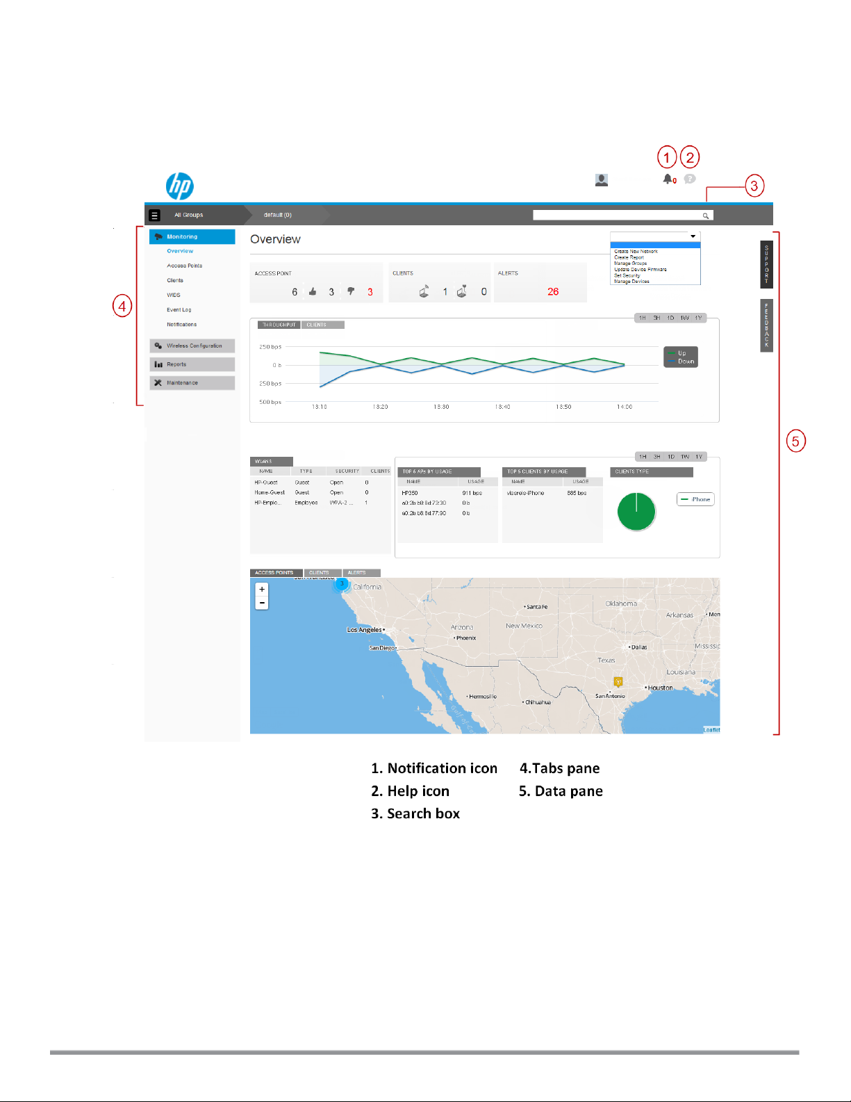
The Monitoring > Overview data pane is displayed on logging into Cloud Network Manager, See Figure 1.
Figure 1: Cloud Network Manager main pane
The main pane consists of:
l Search
l Tabs
l Notifications
l Help
l Data pane
HP Cloud Network Manager | User Guide Cloud Network Manager user interface | 13
Page 14

In addition, there are links to Support and Feedback on the right edge of the screen.
Search
The Search box allows administrators to search for an AP, client, or a network. When you enter text in the search
box, the search function suggests matching keywords and allows you to automatically complete the search text
entry.
Tabs
The left pane lists the Cloud Network Manager function tabs.
n Monitoring
n Wireless configuration
n Reports
n Maintenance
Each tab appears in a compressed view by default. The individual tabs can be expanded or collapsed by clicking
on them.
For more information, see:
l Monitoring
l Wireless configuration
l Reports
l Maintenance
Monitoring
You can monitor the APs and their associated clients using the Overview, Access Points, Clients, WIDS, and
Event Log panes in the Cloud Network Manager.
Wireless configuration
The Wireless Configuration tab allows you to configure the wireless or wired network, APs, intrusion, Radio
Frequency (RF), security settings, Dynamic Host Control Protocol (DHCP), services, and system parameters.
Reports
The Reports tab provides network reports, security reports, and Peripheral Component Interconnect (PCI)
compliance reports. You can export the report and send it to an email account.
Maintenance
The Maintenance tab allows you to maintain the network and provides details on the firmware version, license and
so on.
Labels, variables, groups, and overrides
Labels are tags on APs that filter APs for monitoring and reporting purposes. An AP can have multiple labels. For
example, consider an AP labeled as "Building 25" and "Lobby". These tags identify if the location of the AP is
within the enterprise campus and the building. The APs in other buildings can also be tagged with “Lobby” to enable
all the APs in the lobby of all these buildings in the campus. To filter and monitor APs in the lobbies of all the
campus buildings, tag all the APs in the lobby with the label “Lobby”. Labels can also be used to determine the
ownership, departments, and functions of APs.
14 | Cloud Network Manager user interface HP Cloud Network Manager | User Guide
Page 15
Variables are AP parameters that can be configured, but cannot inherit values from the default group. These userdefined parameters are specific to an AP, for example, Virtual Controller (VC) name, IP address, and VLAN.
Therefore, ensure that you set all parameters on all the APs in a cluster.
If one or more VCs are grouped together within a cluster of APs, you can configure the APs associated with each
VC as a single unit from the Cloud Network Manager. These configuration parameters are assigned with the same
default value. You can quickly configure a number of APs using a group.
The group configuration is shared across all the VCs and APs. Sometimes a specific VC may require configuration
that is different from the rest of the configuration shared by the group. The configuration that is different from the
rest of the group is known as Override. Override can be configured when the user clicks on the individual VCs on
the left pane of the UI. Resolve Override refers to removing these configuration specific for a VC and making the
configuration same for all the VCs in a group.
The following example displays how Wireless Intrusion Detection System (WIDS) parameters are resolved for
overrides:
1. Click a Virtual Controller from a group level and change the WIDS parameters. The Override icon for the VC
is displayed.
2. Using Resolve Override allows you to remove the existing configurations for a specific VC and ensuring the
configurations are the same for all VCs in a group.
Notifications
The Notifications icon displays the unacknowledged notifications count at the top right edge of the main pane.
Help
Click the Help icon to view a short description of selected terms and fields in a pane or dialog box.
To activate online help:
1. Click (?) at the top right edge of the Cloud Network Manager main pane.
2. Place your cursor on any text or term displayed.
To disable help mode, click (?) again.
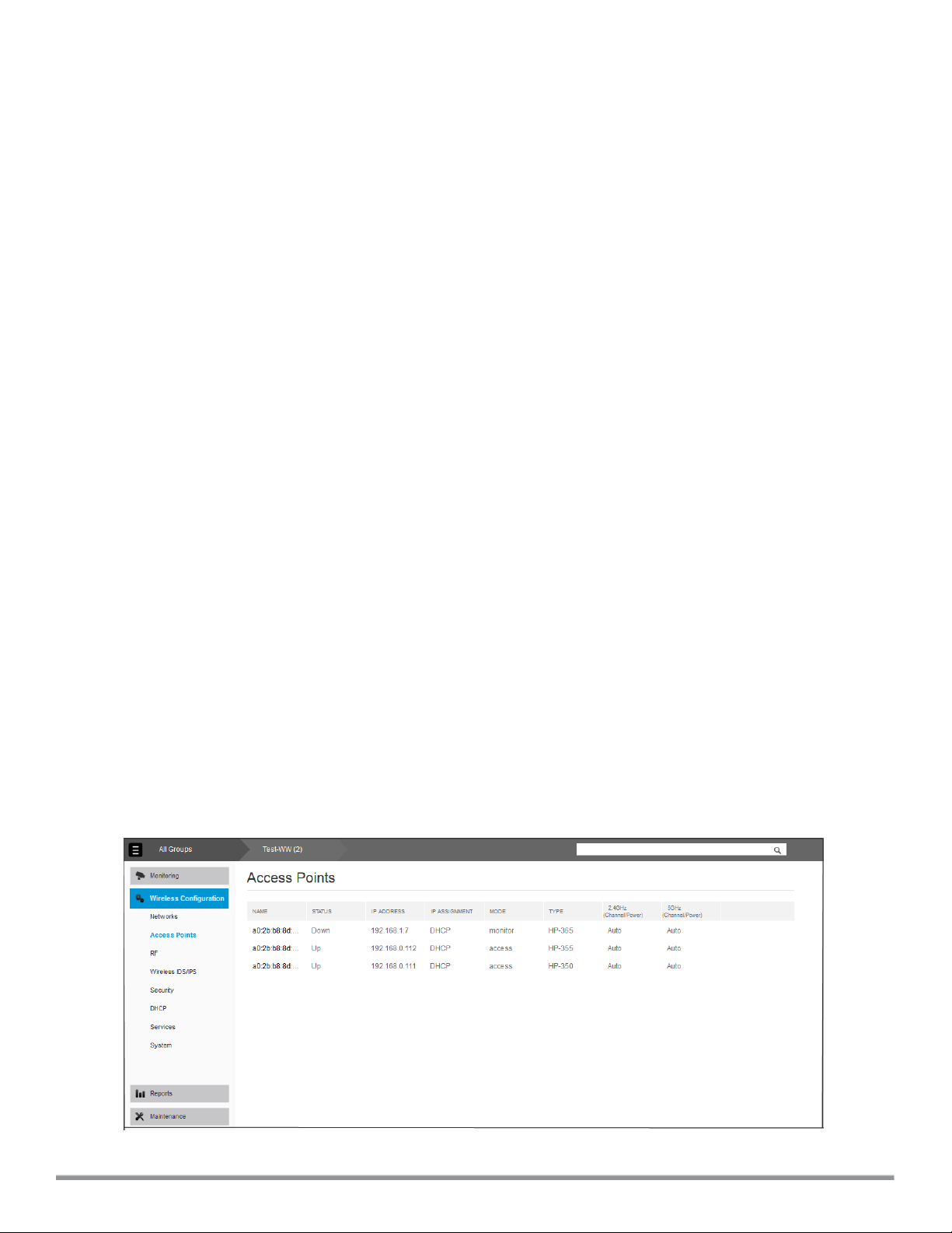
Data pane
Displays detailed information of the tabs and the selected features. The following figure displays the data pane for
Wireless Configuration > Access Points pane.
Figure 2: Sample data pane
HP Cloud Network Manager | User Guide Cloud Network Manager user interface | 15
Page 16

Support
You can contact HP support for troubleshooting Cloud Network Manager by clicking Support at the right edge of
Cloud Network Manager.
Feedback
To help HPimprove the Cloud Network Manager UI, click Feedback and enter your comments.
16 | Cloud Network Manager user interface HP Cloud Network Manager | User Guide
Page 17

Monitoring
The Monitoring tab displays the monitoring pane for Cloud Network Manager.
The monitoring tab consists of:
l Overview
l Access points
l Clients
l WIDS
l Event log
l Notifications
Overview
The Overview pane displays a summary of the networks, clients, and the geographical location of the AP.
Table 2: Contents of the monitoring overview pane
Data pane item Description
ACCESSPOINTS count Displays the total number of APs.
CLIENTS count Displays the total number of clients connected to an AP over a
specified period.
ALERTS count Displays the total number of APs or clients that have alerts.
QUICKLINKS Displays the links to the most frequently used pages in Cloud
Network Manager.
THROUGHPUT graph Displays the aggregate incoming and outgoing data traffic of all APs
over a specified period.
CLIENTS graph Displays the number of clients connected to an AP over a specified
period.
WLANS Displays the list of SSIDs configured.
TOP 5 APs BY USAGE Displays the list of top five APs that are most used on the network.
TOP 5 CLIENTS BY USAGE Displays the list of top five clients utilizing the maximum bandwidth
over the network.
CLIENTSTYPE Displays the different types of clients connected to the network.
Map Displays the geographic location of the APs, clients, and alerts.
You can view the THROUGHPUT graph and CLIENTS graph for a specific timeframe (1 Hour, 3 Hours, 1 Day, 1 Week,
1 Year) by clicking 1H, 3H, 1D, 1W, or 1Y.
HP Cloud Network Manager | User Guide Monitoring | 17
Page 18

Access points
The Access Points pane displays information about the status and location of the APs.
Table 3: Contents of the APs pane
Data pane item Description
FLAGGED AP Displays the APs that are experiencing potential issues with
utilization, noise, and so on. It consists of:
l ACCESS POINTS
l UTIL(%)
l NOISE(dBm)
l ERRORS
l CLIENTS
l MEMORY
l CPU
ACCESSPOINTS Displays the geographic location of the APs. It consists of:
l NAME
l LOCATION
l STATUS
l CLIENTS
l IP ADDRESS
l MODE
l TYPE
l 2.4 GHz
l 5.0 GHz
l VIRTUAL CONTROLLER
l UPTIME
l LABELS
Utilization icon Displays the radio utilization rate of the APs. Depending on the
percentage of utilization, the color of the lines on the Utilization icon
changes from Green > Orange > Red.
l Green— Utilization is less than 50 percent.
l Orange— Utilization is between 50-75 percent.
l Red— Utilization is more than 75 percent.
THROUGHPUT graph Displays the aggregate incoming and outgoing data traffic of all APs
over a specified period.
CLIENTS graph Displays the number of clients connected to an AP over a specified
period.
Map
Displays the geographic location of the APs.
You can view the THROUGHPUT graph and CLIENTS graph for a specific timeframe (1 Hour, 3 Hours, 1 Day, 1 Week,
1 Year) by clicking 1H, 3H, 1D, 1W, or 1Y.
AP details
To view the details of the AP:
Navigate to Monitoring > Access Points pane and click the AP for which you want to view the details under
ACCESS POINTS or FLAGGED AP. The ACCESSPOINT details page is displayed.
18 | Monitoring HP Cloud Network Manager | User Guide
Page 19

Table 4: Contents of the AP details pane
Section Description
DEVICESTATUS Displays the current status of the AP.
CONNECTEDCLIENTS Displays the number of clients that are connected to this AP.
UPLINKTYPE Displays the type of uplink used.
ALERTS Displays the number of alerts generated for this AP.
MAP Displays the geographical location of the AP.
General
GRAPH
l APNAME
l SERIALNUMBER
l MACADDRESS
l IP ADDRESS
l MODE
l MESH ROLE
l UPTIME
l VC NAME
l APMODELTYPE
l FIRMWAREVERSION
l CPUUTILIZATION
l DEVICEMEMORYUSED
l DEVICEMEMORY TYPE
Select a parameter from the drop-down to view their respective
graphs:
l Number of Connected Clients
l Throughput
l RF Channel Utilization
l Number of Neighboring Clients
l Noise Floor
l Errors/Retires/Drops Statistics
Remote Console System pane
On the Access Point details page, click Console Access to view the remote console for the VC.
Clients
The Clients tab displays a list of clients that are connected to the network. The client names are displayed as
links.
Table 5: Contents of the clients pane
Data pane item Description
FLAGGED CLIENTS Displays the clients that are experiencing issues like utilization,
noise, and so on. It consists of the following fields:
l MAC ADDRESS
l IP ADDRESS
l SIGNAL
l SPEED
CLIENTS Displays the geographic location of the APs. It consists of:
HP Cloud Network Manager | User Guide Monitoring | 19
Page 20

Data pane item Description
l MAC ADDRESS
l IP ADDRESS
l USERNAME
l HOSTNAME
l DEVICE TYPE
l ASSOCAP
l SSID
l CONNECTION
l LABELS
THROUGHPUT graph Displays the aggregate incoming and outgoing data traffic of all
clients over a specified period.
DEVICETYPE Displays the type of the device connected to the AP.
Map Displays the geographic location of the clients.
WIDS
The WIDS pane provides an overview of the rogue APs, interfering APs, and the total number of wireless attacks on a
client for a specified period.
Table 6: Contents of the WIDS pane
Data pane item Description
AP TYPE Displays the distribution of foreign AP types detected by the system.
CONFIGURATION Displays the configuration settings for wireless intrusion protection
and detection policies.
IDS ATTACK DETECTED Displays the distribution of IDS attacks detected by the system.
Event log
The Event Log pane displays the event details that occur in the network.
Table 7: Contents of the event log pane
Data pane item Description
DATE/TIME Displays the system date and time at which the event occurred.
AP Displays the MAC address of the AP.
VIRTUALCONTROLLER Displays the name of the AP.
CLIENT Displays the number of clients connected to the AP.
SSID Displays the name of the network.
LEVEL Displays the severity level of the event occurred.
TYPE Displays the type of event log. Example, Security
DESCRIPTION Displays the description of the event that occurred.
Search icon Use this icon to search for a particular event.
20 | Monitoring HP Cloud Network Manager | User Guide
Page 21

Notifications
The Notifications pane displays all types of notification alerts that are detected and unacknowledged by the Cloud
Network Manager.
Table 8: Contents of the notifications pane
Data pane item Description
Notifications
Acknowledge All Acknowledges all the notifications in one click.
Displays all types of notification alerts.
Setting notification alerts
To configure a notification alert:
1. At the top right edge of the main pane, click Notifications icon > Settings icon. The Notification Settings pane
is displayed.
2. Select the notification type from TYPE.
3. Select the event type from EVENT.
4. Select the group type from GROUP.
5. To receive email notifications, select Email and enter the email address.
6. Click Save.
HP Cloud Network Manager | User Guide Monitoring | 21
Page 22

Wireless configuration
The Wireless Configuration tab displays the configuration pane for Cloud Network Manager.
This chapter provides the following information:
l Initial AP configuration on page 22
l Wireless network profiles on page 22
Initial AP configuration
Before connecting to Cloud Network Manager:
l If an AP is shipped with factory default settings, the Cloud Network Manager applies the default configuration
parameters on the AP when it connects to the Cloud Network Manager. The user can change the values in the
default group and the AP inherits this automatically.
l If the AP is operational in subscriber networks, the configuration parameters of an AP were already changed
from factory default settings. When the AP connects to Cloud Network Manager, no configuration is required.
Importing existing configuration from AP
When a preconfigured AP is included in Cloud Network Manager, it is initially listed under unprovisioned group.
To import a configuration to AP:
1. Go to https://portal.hpcloudnetworkmanager.com and log in with your user credentials.
2. Ensure that the AP is connected to the wired network.
3. Click an AP. The Import New Group and Overwrite Existing Config options are displayed.
4. To create a new group, click Import to New Group tab and then click Save.
To overwrite an existing configuration, click Overwrite Existing Config.
5. Click Save.
Cloud Network Manager deletes the existing configuration and applied the group configuration.
The Wireless Configuration tab provides an overall view of your AP configuration. This section provides
configuration information on the following major tabs of the Cloud Network Manager UI:
l Networks
l Access points
l RF
l Wireless IDS/IPS
l Security
l DHCP
l Services
l System
Wireless network profiles
This section provides the following information:
l Understanding wireless network profiles on page 23
HP Cloud Network Manager | User Guide Wirelessconfiguration | 22
Page 23
l Configuring WLAN settings on page 23
l Configuring VLAN settings for a WLAN SSID profile on page 26
l Configuring security settings for a WLAN SSID profile on page 27
l Configuring access rules for a WLAN SSID profile
l Editing a WLAN SSID profile on page 30
l Deleting a WLAN SSID profile on page 30
Understanding wireless network profiles
During start up, a wireless client searches for radio signals or beacon frames that originate from the nearest AP.
After locating the AP, the following transactions occur between the client and the AP:
1. Authentication — The AP communicates with a RADIUS server to validate or authenticate the client.
2. Connection — After successful authentication, the client establishes a connection with the AP.
Network types
Cloud Network Manager wireless networks are categorized as:
l Employee network — An Employee network is a classic Wi-Fi network. This network type is used by the
employees in an organization and it supports passphrase-based or 802.1X based authentication methods.
Employees can access the protected data of an enterprise through the employee network after successful
authentication. The employee network is selected by default during a network profile configuration.
l Voice network —This Voice network type allows you to configure a network profile for devices that provide only
voice services such as handsets or applications that require voice traffic prioritization.
l Guest network —The Guest wireless network is created for guests, visitors, contractors, and any non-
employee users who use the enterprise Wi-Fi network. The VC assigns the IP address for the guest clients.
Captive portal or passphrase based authentication methods can be set for this wireless network. Typically, a
guest network is an un-encrypted network. However, you can specify the encryption settings when configuring
a guest network.
When a client is associated to the voice network, all data traffic is marked and placed into the high priority queue in QoS
(Quality of Service).
To configure a new wireless network profile, complete the following procedures:
1. Configuring WLAN Settings
2. Configuring VLAN Settings
3. Configuring Security Settings
4. Configuring Access Rules for a Network
Configuring WLAN settings
To configure WLAN settings:
1. Select Wireless Configuration > Networks and then click Create New. The CREATE A NEW NETWORK
pane is displayed.
23 | Wireless configuration HP Cloud Network Manager | User Guide
Page 24
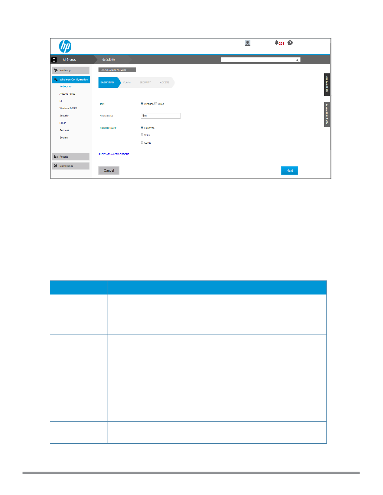
Figure 3: WLAN settings pane
2. For TYPE, select Wireless.
3. Enter a name that is used to identify the network in the Name (SSID) box.
4. Based on the type of network profile, select any of the following options under PRIMARY USAGE:
l Employee
l Voice
l Guest
5. Click SHOW ADVANCED OPTIONS. The advanced options for configuration are displayed. Specify the
following parameters as required.
Table 9: WLAN configuration parameters
Data pane item Description
BROADCAST
FILTERING
Select any of the following values:
l All — The AP drops all broadcast and multicast frames except DHCP and ARP.
l ARP — The AP converts ARP requests to unicast and sends frames directly to
the associated client.
l Disabled — The AP forwards all broadcast and multicast traffic.
DTIM INTERVAL
DTIM INTERVAL
The
period in beacons, which can be configured for every WLAN SSIDprofile. The
DTIMinterval determines how often the AP delivers the buffered broadcast and multicast frames to associated clients in the powersave mode. The default value is 1,
which means the client checks for buffered data on the AP at every beacon. You
can also configure a higher DTIM value for power saving.
MULTICAST
TRANSMISSION
OPTIMIZATION
Enabled
Select
and multicast frames based on the lowest of unicast rates across all associated clients. When this option is enabled, multicast traffic can be sent up to 24 Mbps. The
default rate for sending frames for 2.4 GHz is 1 Mbps and 5.0 GHz is 6 Mbps. This
option is disabled by default.
DYNAMIC
MULTICAST
Select Enabled to allow AP to convert multicast streams into unicast streams over
the wireless link. Enabling Dynamic Multicast Optimization (DMO) enhances the
indicates the Delivery Traffic Indication Message (DTIM)
if you want the AP to select the optimal rate for sending broadcast
HP Cloud Network Manager | User Guide Wirelessconfiguration | 24
Page 25

Data pane item Description
OPTIMIZATION quality and reliability of streaming video, while preserving the bandwidth available
to the non-video clients.
NOTE: When you enable DMO on multicast SSID profiles, ensure that the DMO
feature is enabled on all SSIDs configured in the same VLAN.
DMO CHANNEL
UTILIZATION
THRESHOLD
TRANSMIT
RATES
BANDWIDTH
LIMITS
Wi-Fi
MULTIMEDIA
(WMM)
TRAFFIC
MANAGEMENT
Specify a value to set a threshold for DMO channel utilization. With DMO, the AP
converts multicast streams into unicast streams as long as the channel utilization
does not exceed this threshold. The default value is 90% and the maximum
threshold value is 100%. When the threshold is reached or exceeds the maximum
value, the AP sends multicast traffic over the wireless link.
Specify the following parameters:
l 2.4 GHz — If the 2.4 GHz band is configured on the AP, specify the minimum
and maximum transmission rate. The default value for minimum transmission
rate is 1 Mbps and maximum transmission rate is 54 Mbps.
l 5 GHz — If the 5 GHz band is configured on the AP, specify the minimum and
maximum transmission rate. The default value for minimum transmission rate is
6 Mbps and maximum transmission rate is 54 Mbps.
Under BANDWI DTH LIMITS:
l AIRTIME — Select this to specify an aggregate amount of airtime that all clients
in this network can use for sending and receiving data. Specify the airtime
percentage.
l EACH RADIO — Select this to specify an aggregate amount of throughput that
each radio is allowed to provide for the connected clients.
Configure the following options for WMM traffic management. WMM supports voice,
video, best effort, and background access categories. You can allocate a higher
bandwidth for voice and video traffic than other types of traffic based on the
network profile. Specify a percentage value for the following parameters:
l BACKGROUND WMM SHARE — Allocates bandwidth for background traffic
such as file downloads or print jobs.
l BEST EFFORT WMM SHARE — Allocates bandwidth or best effort traffic such
as traffic from legacy devices or traffic from applications or devices that do not
support QoS.
l VIDEO WMM SHARE — Allocates bandwidth for video traffic generated from
video streaming.
l VOICE WMM SHARE — Allocates bandwidth for voice traffic generated from the
incoming and outgoing voice communication.
In a non-WMM or hybrid environment, where some clients are not WMM-capable,
you can allocate higher values for BEST EFF ORT WMMshare and VOICE WMM
SHARE to allocate a higher bandwidth to clients transmitting best effort and voice
traffic.
CONTENTFI LTERING
Select Enabled to route all DNS requests for the non-corporate domains to
OpenDNS on this network.
BAND Select a value to specify the band at which the network transmits radio signals. You
can set the band to 2. 4 GHz, 5 GHz, or All. The All option is selected by default.
INACTIVITYTIMEOUT
Specify an interval for session timeout. If a client session is inactive for the
specified duration, the session expires and the users are required to log in again.
The minimum value is set to 60 seconds and the default value is 1000 seconds.
HIDE SSI D Select this if you do not want the SSID (network name) to be visible to users.
DISABLE SSI D Select this if you want to disable the SSID. On selecting this, the SSID will be
disabled, but will not be removed from the network. By default, all SSIDs are
enabled.
25 | Wireless configuration HP Cloud Network Manager | User Guide
Page 26

Data pane item Description
CAN BE USED
WITHOUT
UPLINK
MAXCLIENTS
THRESHOLD
LOCALPROBE
REQUEST
THRESHOLD
Select this if you do not want SSID profile to use uplink.
Specify the maximum number of clients that can be configured for each BSSID on a
WLAN. You can specify a value within the range of 0 to 255. The default value is
64.
Specify a threshold value to limit the number of incoming probe requests. When a
client sends a broadcast probe request frame to search for all available SSIDs, this
option controls system response for this network profile and ignores probe
requests if required. You can specify a Received Signal Strength Indication (RSSI)
value within range of 0 to 100 dB.
6. Click Next to configure VLAN settings. For more information, see Configuring VLAN settings for a WLAN SSID
profile on page 26.
Configuring VLAN settings for a WLAN SSID profile
If you are creating a new SSID profile, complete the WLANsettings procedure before configuring VLAN. For
information, see Configuring WLAN settings on page 23.
To configure VLAN settings for an SSID:
1. In VLAN, select any of the following options for CLIENT IP ASSIGNMENT:
l Virtual Controller Assigned — On selecting this option, the client obtains the IP address from the VC. The
VC creates a private subnet and VLAN on the AP for the wireless clients. The network address translation
for all client traffic that goes out of this interface is carried out at the source. This setup eliminates the need
for complex VLAN and IP address management for a multi-site wireless network. For more information on
DHCP scopes and server configuration, see DHCP configuration on page 65.
l Network Assigned — Select this option to obtain the IP address from the network.
2. If Network Assigned is selected, specify any of the following options for the CLIENT VLAN ASSIGNMENT.
l Default — On selecting this option, the client obtains the IP address in the same subnet as the APs. By
default, the client VLAN is assigned to the native VLAN on the wired network.
l Static — On selecting this option, you need to specify a single VLAN, a comma separated list of VLANS, or
a range of VLANs for all clients on this network. Select this option for configuring VLAN pooling.
l Dynamic — On selecting this option, you can assign the VLANs dynamically from a DHCP server. To create
VLAN assignment rules:
a. Click New to assign the user to a VLAN. The NEW VLAN ASSIGNMENT RULE pane is
displayed.
b. Enter the following information:
l ATTRIBUTE — Select an attribute returned by the RADIUS server during authentication.
l OPERATOR — Select an operator for matching the string.
l STRING — Enter the string to match.
l VLAN — Enter the VLAN to be assigned.
3. Click Next to configure security settings for the employee network. For more information, see Configuring
security settings for a WLAN SSID profile on page 27.
HP Cloud Network Manager | User Guide Wirelessconfiguration | 26
Page 27
Configuring security settings for a WLAN SSID profile
This section describes the procedure for configuring security settings for employee and voice network only. For
information on guest network configuration, see Captive portal for guest access on page 56 .
If you are creating a new SSID profile, configure the WLANand VLAN settings before defining security settings. For
more information, see Configuring WLAN settings on page 23 and Configuring VLAN settings for a WLAN SSID profile
on page 26.
Configuring security settings for an employee or voice network
To configure security settings for an employee or voice network:
1. In Security, specify any of the following for SECURITY LEVEL:
l Enterprise —On selecting enterprise security level, the authentication options applicable to the enterprise
network is displayed.
l Personal — On selecting personal security level, the authentication options applicable to the personalized
network is displayed.
l Open — On selecting Open security level, the authentication options applicable to an open network is
displayed:
The default security setting for a network profile is Personal.
2. Based on the security level specified, specify the following parameters:
Table 10: Configuration parameters for WLAN security settings
Data pane item Description
KEY
MANAGEMENT
For Enterprise security level, select any of the following options from
KEYMANAGEMENT:
l WPA-2 Enterprise
l Both (WPA-2 & WPA)
l WPA Enterprise
l Dynamic WEP with 802.1X — If you do not want to use a session key from the
RADIUS Server to derive pairwise unicast keys, set SESSION KEY FOR
LEAP to Enabled. This is required for old printers that use dynamic WEP
through Lightweight Extensible Authentication Protocol (LEAP)
authentication. The SESSION KEY FOR LEAP feature is Disabled by default.
NOTE: When W PA-2 Enterprise and Both (W PA2-WPA) encryption types are
selected and if 802.1x authentication method is configured, the
OPPURTUNISTIC KEY CACHING (OKC) is enabled by default. If OKC is
enabled, a cached Pairwise Master Key (PMK) is used when the client roams to
a new AP. This allows faster roaming of clients without the need for a complete
802.1x authentication. OKC roaming can be configured only for the Enterprise
security level.
For Personal security level, select an encryption key from KEY MANAGEMENT.
l For WPA-2 Personal, WPA Personal, and Both (WPA-2&WPA) keys, specify
the following parameters:
l PASSPHRASE FORMAT : Select a passphrase.format. The
options are available are 8-63 alphanumeric characters and
64 hexadecimal characters.
l Enter a passphrase in PASSPHRASE and reconfirm.
l For ST ATI C WEP, specify the following parameters:
l Select an appropriate value for WEP KEY SIZE from the WEP
key size. You can specify 64-bit or 128-bit .
27 | Wireless configuration HP Cloud Network Manager | User Guide
Page 28

Data pane item Description
l Select an appropriate value for Tx key from Tx KEY.
l Enter an appropriate WEP KEY and reconfirm.
802.11r
ROAMING
To enable 802.11r roaming, select Enabled from 802.11r ROAMING. Selecting
this enables fast BSS transition.
The fast BSS transition mechanism minimizes the delay when a client transitions
from one BSS to another within the same cluster.
TERMINATION To terminate the EAP portion of 802.1X authentication on the AP instead of the
RADIUS Server, set TERMI NATION to Enabled.
Enabling TERMINATION can reduce network traffic to the external RADIUS
Server by terminating the authorization protocol on the AP. By default, for 802.1X
authorization, the client conducts an EAP exchange with the RADIUS Server,
and the AP acts as a relay for this exchange.
When TERMINATIONTermination is enabled, the AP acts as an authentication
server and terminates the outer layers of the EAP and relays only the innermost
layer to the external RADIUS Server.
NOTE: If you are using LDAP for authentication, ensure that AP termination is
configured to support EAP.
AUTHENTICATIO
Select any of the following options from AUTHENTI CATION SERVER 1:
N SERVER 1 and
AUTHENTICATIO
N
SERVER 2
l Select an authentication server from the list if an external server is already
configured.
l Select New to configure any of the following servers as an external server:
l RADIUSServer
l LDAP Server
For information on configuring external servers, see Configuring an external
server for authentication on page 49.
l To use an internal server, select Internal server and add the clients that are
required to authenticate with the internal RADIUS Server. Click Users to add
the users.
If an external server is selected, you can also configure another authentication
server.
LOAD
BALANCING
REAUTH
INTERVAL
BLACKLISTING
Set this to Enabled if you are using two RADIUS authentication servers, to
balance the load across these servers.
Specify a value for REAUTH INTERVAL. When set to a value greater than zero,
APs periodically reauthenticate all associated and authenticated clients.
To enable blacklisting of the clients with a specific number of authentication failures, select
Enabled
AUTHENTICATION FAI LURES
of times specified in
BLACKLISTING
from
and specify a value for
. The users who fail to authenticate the number
MAX AUTHENTICATI ON F AILURES
MAX
field are dynamically
blacklisted.
ACCOUNTING To enable accounting, select Enabled from ACCOUNTING. On setting this
option to Enabled, APs post accounting information to the RADIUS server at the
specified ACCOUNTING INTERVAL.
AUTHENTICATIO
N
SURVIVABILITY
To enable authentication survivability, set AUTHENTICAT ION SURVIVABILITY
to Enabled. Specify a value in hours for CACHE T IMEOUT to set the duration
after which the authenticated credentials in the cache expires. When the cache
expires, the clients are required to authenticate again. You can specify a value
HP Cloud Network Manager | User Guide Wirelessconfiguration | 28
Page 29

Data pane item Description
within range of 1 to 99 hours and the default value is 24 hours.
MAC
AUTHENTICATIO
N
DELIMITER
CHARACTER
UPPERCASE
SUPPORT
To enable MAC address based authentication for Personal and Open security
levels, set MAC AUTHENTICATION to Enabled.
For Enterprise security level, the following options are available:
l PERFORM MAC AUT HENT ICATION BEFORE 802.1X — Select this to use
802.1X authentication only when the MAC authentication is successful.
l MAC AUTHENTICATION FAI L-THRU — On selecting this, the 802.1X
authentication is attempted when the MAC authentication fails.
Specify a character (for example, colon or dash) as a delimiter for the MAC
address string. When configured, the AP uses the delimiter in the MAC authentication request. For example, if you specify the colon as a delimiter, MAC
addresses in the xx:xx:xx:xx:xx:xx format are used. If the delimiter is not specified,
the MAC address in the xxxxxxxxxxxx format is used.
This option is available only when MAC authentication is enabled.
Set to Enabled to allow the AP to use uppercase letters in MAC address string for
MAC authentication.
This option is available only if MAC authentication is enabled.
3. Click Next to configure access rules. For more information, see Configuring access rules for a WLAN SSID
profile on page 29.
Configuring access rules for a WLAN SSID profile
This section describes the procedure for configuring security settings for employee and voice network only. For
information on guest network configuration, see Captive portal for guest access on page 56.
If you are creating a new SSID profile, complete the WLANSettings and configure VLAN and security parameters, before
defining access rules. For more information, see Configuring WLAN settings on page 23, Configuring VLAN settings for
a WLAN SSID profile on page 26, and Configuring security settings for a WLAN SSID profile on page 27.
You can configure up to 64 access rules for an employee, voice, or guest network. To configure access rules for a
guest network, see Configuring a WLANSSID for guest access on page 57
To configure access rules for an employee or voice network:
1. In Access Rules, select any of the following types of access control:
l Unrestricted — Select this to set unrestricted access to the network.
l Network-based — Select Network-based to set common rules for all users in a network. The Allow any to
all destinations access rule is enabled by default. This rule allows traffic to all destinations. To define an
access rule:
a. Click (+) icon.
b. Select appropriate options in the New Rule pane.
c. Click OK.
l Role based — Select Role based to enable access based on user roles. For role-based access control:
n Create a user role if required.
29 | Wireless configuration HP Cloud Network Manager | User Guide
Page 30

n Create access rules for a specific user role. You can also configure an access rule to enforce Captive
portal authentication for an SSIDthat is configured to use 802.1X authentication method. For more
information, see Configuring captive portal roles for an SSID on page 63.
n Create a role assignment rule.
2. Click Finish.
Editing a WLAN SSID profile
To edit a WLAN SSID profile:
1. In the Wireless Configuration > Networks tab, select the network that you want to edit.
2. Click Edit. The Edit network pane is displayed.
3. Modify the required settings.
4. Click Save Settings to save the modifications.
Deleting a WLAN SSID profile
To delete a WLAN SSID profile:
1. In the Wireless Configuration > Networks tab, click the network that you want to delete.
2. Click Delete. A delete confirmation pane is displayed.
3. Click OK.
General configuration tasks
This section describes the general configuration tasks to perform when an AP is set up.
l Basic configuration tasks on page 31
l Additional configuration tasks on page 33
HP Cloud Network Manager | User Guide Wirelessconfiguration | 30
Page 31

Figure 4: Configuration system tab
Basic configuration tasks
This section describes the following basic configuration tasks that can be performed in the System > GENERAL
tab after an AP is set up:
l Modifying the AP name on page 31
l Configuring VC IP address on page 32
l Configuring time zone on page 32
l Configuring a preferred band on page 32
l Configuring an NTP server on page 32
Modifying the AP name
To change the name of an AP:
1. Select Wireless Configuration > System. The System details are displayed.
2. In GENERAL, click Edit Values next to NAME. The Edit VC Name pane is displayed.
31 | Wireless configuration HP Cloud Network Manager | User Guide
Page 32

3. Enter the name of the AP in NAME.
4. Click Save.
Configuring VC IP address
You can specify a single static IP address that is used to manage a multi-AP Cloud Network Manager network.
This IP address is automatically provisioned on a shadow interface on the AP that takes the role of a VC. The AP
sends three Address Resolution Protocol (ARP) messages with the static IP address and its MAC address to
update the network ARP cache.
To configure the VC name and IP address:
1. Select Wireless Configuration > System. The System details are displayed.
2. In GENERAL, click Edit Values next to VIRTUAL CONTROLLER IP. The Edit IP Address pane is
displayed.
3. Enter the IPaddress in IP ADDRESSES.
4. Click Save.
Configuring time zone
1. Select Wireless Configuration > System. The System details are displayed.
2. In GENERAL, select a time zone from TIMEZONE.
3. Click Save Settings.
Configuring a preferred band
To configure a preferred band for an AP:
1. Select Wireless Configuration > System. The System details are displayed.
2. In GENERAL, set the frequency using PREFERRED BAND for single-radio APs.
3. Click Save Settings.
Reboot the AP after configuring the radio profile for the changes to take effect.
Configuring an NTP server
To facilitate communication between various elements in a network, time synchronization between the elements
and across the network is critical. Time synchronization allows you to:
l Trace and track security gaps, network usage, and troubleshoot network issues.
l Map an event on one network element to a corresponding event on another.
l Maintain accurate time for billing services and similar.
The Network Time Protocol (NTP) helps obtain the precise time from a server and regulate the local time in each
network element. If NTP server is not configured in the Cloud Network Manager network, an AP reboot may lead to
variation in time data.
The NTP server is set to pool.nt p.org by default.
To configure an NTP server:
1. Select Wireless Configuration > System. The System details are displayed.
2. In GENERAL, enter the IP address or the URL (domain name) of the NTP server in NTP SERVER.
HP Cloud Network Manager | User Guide Wirelessconfiguration | 32
Page 33

3. Click Save Settings.
Additional configuration tasks
This section describes the following additional tasks that can be performed after an AP is set up:
l Configuring VC VLAN on page 33
l Configuring auto join mode on page 33
l Configuring LED display on page 33
l Disabling inter-user bridging on page 34
l Preventing local routing between clients on page 34
l Enabling dynamic CPU management on page 34
Configuring VC VLAN
123
The IP configured for the VC can be in the same subnet as AP or can be in a different subnet. Ensure that
you configure the VC VLAN, gateway, and subnet mask details only if the VC IP is in a different subnet.
To configure the VC VLAN:
1. Select Wireless Configuration > System. The System details are displayed.
2. In GENERAL, enter subnet mask details in VIRTUAL CONTROLLER NETMASK.
3. Enter a gateway address in VIRTUAL CONTROLLER GATEWAY.
4. Enter VC VLAN in VIRTUAL CONTROLLERVLAN.
Ensure that VC VLAN is not the same as native VLAN of the AP.
5. Click Save Settings.
Configuring auto join mode
The auto join mode feature allows APs to automatically discover the VC and join the network.
The Auto Join Mode feature is enabled by default. If the auto join mode feature is disabled, a New link is displayed
in the Access Points tab. Click this link to add APs to the network. If this feature is disabled, the inactive APs are
displayed in red.
Enabling or disabling auto join mode
To enable or disable auto join mode:
1. Select Wireless Configuration > System. The System details are displayed.
2. In GENERAL, set the auto join mode to deny or allow from AUTO JOIN MODE by selecting Enabled or
Disabled.
3. Click Save Settings.
Configuring LED display
To enable or disable LEDdisplay for all APs in a cluster:
1. Select Wireless Configuration > System. The System details are displayed.
2. In GENERAL, set the LED display to Enabled or Disabled.
3. Click Save Settings.
33 | Wireless configuration HP Cloud Network Manager | User Guide
Page 34

The LED display is always in the Enabled mode during the anAP reboot.
Disabling inter-user bridging
If you have security and traffic management policies defined in upstream devices, you can disable bridging traffic
between two clients connected to the same AP on the same VLAN. When inter-user bridging is denied, the clients
can connect to the internet but cannot communicate with each other, and the bridging traffic between the clients is
sent to the upstream device to make the forwarding decision.
To disable inter-user bridging:
1. Select Wireless Configuration > System. The Configuration-System details are displayed.
2. In GENERAL, set the DENY INTER USER BRIDGING to Enabled.
3. Click Save Settings.
Preventing local routing between clients
If you have security and traffic management policies defined in upstream devices, you can disable routing traffic
between two clients connected to the same AP on different VLANs. When local routing is disabled, the clients can
connect to the internet but cannot communicate with each other, and the routing traffic between the clients is sent
to the upstream device to make the forwarding decision.
You can disable local routing through:
1. Select Wireless Configuration > System. The System details are displayed.
2. In GENERAL, set DENY LOCAL ROUTING to Enabled.
3. Click Save Settings.
Enabling dynamic CPU management
APs perform various functions such as wired and wireless client connectivity and traffic flows, wireless security,
network management, and location tracking.If an AP is overloaded, prioritize the platform resources across
different functions. Typically, the APs manage resources automatically in real time. However, under special
circumstances, if dynamic resource management needs to be enforced or disabled altogether, the dynamic CPU
management feature settings can be modified.
To configure dynamic CPU management:
1. Select Wireless Configuration > System. The System details are displayed.
2. In GENERAL, select any of the following options from DYNAMIC CPU UTILIZATION.
n Automatic — When selected, the CPU management is enabled or disabled automatically during run-time.
This decision is based on real time load calculations taking into account all different functions that the CPU
needs to perform. This is the default and recommended option.
n Always Disabled in all APs — When selected, this setting disables CPU management on all APs, typically
for small networks. This setting protects user experience.
n Always Enabled in all APs — When selected, the client and network management functions are protected.
This setting helps in large networks with high client density.
3. Click Save Settings.
Advanced configuration tasks
This section describes the procedures for configuring settings that are specific to an AP in the cluster.
l Customizing AP parameters on page 35
HP Cloud Network Manager | User Guide Wirelessconfiguration | 34
Page 35

l Configuring radio profiles for an AP on page 35
l Configuring uplink VLANfor an AP on page 36
l Obtaining IP address on page 36
Customizing AP parameters
To customize the parameters of an AP:
1. Select Wireless Configuration > Access Points and click the AP you want to customize.
2. Click Edit. The edit pane for modifying AP details is displayed.
3. Under BASIC INFO, you can modify the name of the AP by entering the name in NAME. You can specify a
name of up to 32 ASCII characters.
4. Select GET IP ADDRESS FROM DHCP SERVER option to receive an IP address from the DHCP server.
5. If you select Static option to specify a static IP address, the following fields are displayed:
a. Enter the new IP address for the AP in IP ADDRESS.
b. Enter the subnet mask of the network in NETMASK.
c. Enter the IP address of the default gateway in DEFAULT GATEWAY.
d. Enter the IP address of the DNS server in DNS SERVER.
e. Enter the domain name in DOMIANNAME.
6. Click Save Settings and reboot the AP.
Configuring radio profiles for an AP
You can configure a radio profile on an AP either manually or by using the Advanced Radio Resource Management
(ARRM) feature.
ARRM is enabled on Cloud Network Manager by default. It automatically assigns appropriate channel and power
settings for the APs. For more information on ARRM, see Advanced radio resource management on page 37.
Configuring ARRMassigned radio profiles for an AP
To enable ARRM assigned radio profiles:
1. Select Wireless Configuration > Access Points and click the AP to modify.
2. Click Edit. The edit pane for modifying AP details is displayed.
3. Select RADIO. The RADIO details are displayed.
4. Ensure that an appropriate mode is selected.
5. Select the Advanced radio management assigned option under the bands that are applicable to the AP
configuration.
6. Click Save Settings.
Configuring radio profiles manually for AP
To manually configure radio settings:
1. Select Wireless Configuration > Access Points and click the AP for which you want to enable ARRM.
2. Click Edit and select RADIO.
3. Ensure that an appropriate mode is selected.
By default the channel and power for an AP are optimized dynamically using ARRM. You can override ARRM
on the 2.4 GHz and 5 GHz bands and set the channel and power if desired.
35 | Wireless configuration HP Cloud Network Manager | User Guide
Page 36

When radio settings are assigned manually by the administrator, the ARRMis disabled.
The following table describes various configuration modes for an AP.
Table 11: AP radio modes
Mode Description
ACCESS In Access mode, an AP serves clients, while also monitoring for rogue APs in the back-
ground.
MONITOR In Monitor mode, an AP acts as a dedicated monitor, scanning all channels for rogue
APs and clients.
SPECTRUMMONITOR In Spectrum Monitor mode, an AP functions as a dedicated full-spectrum RF monitor,
scanning all channels. It detects interference from neighboring APs or from such as
microwaves and cordless phones.
In the Monitor and Spectrum Monitor modes, the APs do not provide access services to clients.
4. If the ACCESS mode is selected, perform the following actions:
a. Select Administrator assigned in 2.4 GHz and 5 GHz BAND.
b. From CHANNEL, select the appropriate channel number for both 2.4 GHz and 5 GHz BAND.
c. Enter appropriate transmit power value in TRANSMITPOWER in 2.4 GHz and 5 GHz BAND.
5. Click Save Settings.
Configuring uplink VLANfor an AP
Cloud Network Manager supports a management VLAN for the uplink traffic on an AP. You can configure an uplink
VLANwhen an AP needs to be managed from a non-native VLAN. After an AP is provisioned with the uplink
management VLAN, all management traffic sent from the AP is tagged with the management VLAN.
Ensure that the native VLAN of the AP and uplink are not the same.
To configure the uplink management VLAN on an AP:
1. Select Wireless Configuration > Access Points and click the AP to modify.
2. Click Edit. The Edit pane for modifying AP details is displayed.
3. Click UPLINK and specify the VLAN in UPLINK MANAGEMENT VLAN.
4. Click Save Settings.
5. Reboot the AP.
Obtaining IP address
You can either specify a static IP address or allow the AP to obtain an IP address from a DHCP server. By default,
the APs obtain IP address from a DHCP server.
To specify a static IP address for the AP.
HP Cloud Network Manager | User Guide Wirelessconfiguration | 36
Page 37

1. Select Wireless Configuration > Access Points and click the AP to modify.
2. Click Edit. The edit pane for modifying the AP details is displayed.
3. Under BASIC INFO, select Static to specify a static IP address. The following fields are displayed:
a. Enter the new IP address for the AP in IP ADDRESS.
b. Enter the subnet mask of the network in NETMASK.
c. Enter the IP address of the default gateway in DEFAULT GATEWAY.
d. Enter the IP address of the Domain Name System (DNS) server in DNS SERVER.
e. Enter the domain name in DOMAIN NAME.
4. Click Save Settings and reboot the AP.
Advanced radio resource management
This section provides the following information:
l ARRM overview on page 37
l Configuring ARRM on an AP on page 39
l Configuring radio settings for an AP on page 42
ARRM overview
ARRM is a radio frequency management technology that optimizes WLAN performance even in the networks with
highest traffic by dynamically and intelligently choosing the best 802.11 channel and transmitting power for each
AP in its current RF environment. ARRM works with all standard clients, across all operating systems, while
remaining in compliance with the IEEE 802.11 standards. It does not require any proprietary client software to
achieve its performance goals. ARRM ensures low-latency roaming, consistently high performance, and maximum
client compatibility in a multi-channel environment. By ensuring the fair distribution of available Wi-Fi bandwidth to
mobile devices, ARRM ensures that data, voice, and video applications have sufficient network resources at all
times. ARRM allows mixed 802.11a, b, g, n, and ac client types to inter operate at the highest performance levels.
Channel or power assignment
The channel or power assignment feature automatically assigns channel and power settings for all the APs in the
network according to changes in the RF environment. This feature automates many setup tasks during network
installation and the ongoing operations when RF conditions change.
Voice aware scanning
The Voice Aware scanning feature prevents an AP supporting an active voice call from scanning for other channels
in the RF spectrum and allows an AP to resume scanning when there are no active voice calls. This significantly
improves the voice quality when a call is in progress and simultaneously delivers the automated RF management
functions. By default, this feature is enabled.
Load aware scanning
The Load Aware Scanning feature dynamically adjusts scanning behavior to maintain uninterrupted data transfer
on resource intensive systems when the network traffic exceeds a predefined threshold. The APs resume
complete monitoring scans when the traffic drops to the normal levels. By default, this feature is enabled.
Band steering mode
The Band Steering feature assigns the dual-band capable clients to the 5 GHz band on dual-band APs. This feature
reduces co-channel interference and increases available bandwidth for dual-band clients, because there are more
37 | Wireless configuration HP Cloud Network Manager | User Guide
Page 38

channels on the 5 GHz band than on the 2.4 GHz band. For more information, see Configuring ARRM on an AP on
page 39.
HP MotionAware
The HP MotionAware feature continually monitors a RF neighborhood of the client to provide ongoing client
bandsteering and load balancing, and enhanced AP reassignment for roaming mobile clients. This feature
supersedes the legacy bandsteering and spectrum load balancing features, which, unlike HP MotionAware, do not
trigger AP changes for clients already associated to an AP.
When HP MotionAware is enabled on 802.11n capable APs, the HP MotionAware feature overrides any settings
configured for the legacy bandsteering, station handoff assist or load balancing features. 802.11ac-capable APs do not
support the legacy bandsteering, station hand off or load balancing settings, so these APs must be managed using HP
MotionAware.
When the HP MotionAware feature is enabled on an AP, the AP measures the RF health of its associated clients.
If one of the three mismatch conditions described below are met, clients are moved from one AP to another for
better performance and client experience. The HP MotionAware feature is supported only within an AP cluster.
The following client or AP mismatch conditions are managed by the HP MotionAware feature:
l Dynamic Load Balancing: HP MotionAware balances clients across APs on different channels, based upon the
client load on the APs and the SNR levels the client detects from an underutilized AP. If an AP radio can
support additional clients, the AP participates in HP MotionAware load balancing and clients can be directed to
that AP radio, subject to predefined SNR thresholds.
l Sticky Clients: The HP MotionAware feature also helps mobile clients that tend to stay associated to an AP
despite low signal levels. APs using HP MotionAware continually monitor the client's RSSI as it roams
between APs, and move the client to an AP when a better radio match can be found. This prevents mobile
clients from remaining associated to an APs with less than ideal RSSI, which can cause poor connectivity and
reduce performance for other clients associated with that AP.
l Band Steering: APs using the HP MotionAware feature monitor the RSSI for clients that advertise a dual-band
capability. If a client is currently associated to a 2.4 GHz radio and the AP detects that the client has a good
RSSI from the 5 GHz radio, the controller attempts to steer the client to the 5 GHz radio, as long as the 5 GHz
RSSI is not significantly worse than the 2.4 GHz RSSI, and the AP retains a suitable distribution of clients on
each of its radios.
By default, the HP MotionAware feature is disabled. For information on HP MotionAware configuration on an AP,
see Configuring ARRM on an AP on page 39.
Spectrum load balancing is integrated with the HP MotionAware feature. HP MotionAware allows the APs in a cluster to
be divided into several logical AP RF neighborhood called domains, which share the same clients. The VC determines
the distribution of clients and balances client load across channels, regardless of whether the AP is responding to the
wireless probe requests of the client.
Airtime fairness mode
The Airtime Fairness feature provides equal access to all clients on the wireless medium, regardless of client type,
capability, or operating system, thus delivering uniform performance to all clients. This feature prevents the clients
from monopolizing resources.
AP control
The following AP control features are supported:
HP Cloud Network Manager | User Guide Wirelessconfiguration | 38
Page 39

l Customize Valid Channels — You can customize Valid 5 GHz channels and Valid 2.4 GHz channels for 20
MHz and 40 MHz channels in the AP. The administrators can configure the ARRM channels in the channel
width window. The valid channels automatically show in the static channel assignment data pane.
l Minimum Transmit Power — This indicates the minimum EIRP from 3 to 33 dBm in 3 dBm increments. You
may also specify a special value of 127 dBm for regulatory maximum to disable power adjustments for
environments such as outdoor mesh links. A higher power level setting may be constrained by the local
regulatory requirements and AP capabilities. If the minimum transmission EIRP setting configured on an AP is
not supported by the AP model, this value is reduced to the highest supported power setting. The default value
is for minimum transmit power is 18 dBm.
l Maximum Transmit Power — This indicates the maximum Effective Isotropic Radiated Power (EIRP) from 3 to
33 dBm in 3 dBm increments. Higher power level settings may be constrained by local regulatory requirements
and AP capabilities. If the maximum transmission EIRP configured on an AP is not supported by the AP model,
the value is reduced to the highest supported power setting. The default value for maximum transmit power is
127 dBm.
l HP MotionAware — When Enabled, ARRM does not change channels for the APs with active clients, except
for high priority events such as radar or excessive noise. This feature must be enabled in most deployments for
a stable WLAN. If the HP MotionAware mode is Disabled, the AP may change to a more optimal channel,
which change may disrupt current client traffic for a while. The HP MotionAware option is Enabled by default.
When the HP MotionAware ARRM is disabled, channels can be changed even when the clients are active on a BSSID.
l Scanning — When ARRM is enabled, the AP dynamically scans all 802.11 channels within its 802.11
regulatory domain at regular intervals and reports to the AP. This scanning report includes WLAN coverage,
interference, and intrusion detection data.
l Wide Channel Bands — This feature allows administrators to configure 40 MHz channels in the 2.4 GHz and
5.0 GHz bands. 40 MHz channels are essentially two 20 MHz adjacent channels that are bonded together. 40
MHz channel effectively doubles the frequency bandwidth available for data transmission.
Monitoring the network with ARRM
When ARRM is enabled, anAP dynamically scans all 802.11 channels within its 802.11 regulatory domain at
regular intervals and sends reports on network (WLAN) coverage, interference, and intrusion detection to a VC.
ARRM metrics
ARRM computes coverage and interference metrics for each valid channel, chooses the best performing channel,
and transmit power settings for each AP RF environment. Each AP gathers other metrics on its ARRM-assigned
channel to provide a snapshot of the current RF health state.
Configuring ARRM on an AP
To configure ARRM features such as band steering, spectrum load balancing, and airtime fairness mode:
1. Select Wireless Configuration > RF > ARRM. The ARRM details are displayed.
2. Configure the following parameters for BAND STEERING MODE:
Table 12: Band steering mode configuration parameters
Data pane item Description
Prefer 5 G Hz Selectthis option to use band steering in the 5 GHz mode. On selecting this, the AP
39 | Wireless configuration HP Cloud Network Manager | User Guide
Page 40

Data pane item Description
steers the client to the 5 GHz band (if the client is 5 GHz capable), but allows the
client connection on the 2.4 GHz band if the client persistently attempts for 2.4 GHz
association.
Force 5 G Hz Select this option to enforce 5 GHz band steering mode on the APs.
Balance Bands Select this option to allow the AP to balance the clients across the two radios to
best utilize the available 2.4 GHz bandwidth. This feature takes into account the
fact that the 5 GHz band has more channels than the 2.4 GHz band, and that the 5
GHz channels operate in 40 MHz, while the 2.5 GHz band operates in 20MHz.
Disable Select this option to allow the clients to select the band to use.
3. For AIRTIME FAIRNESS MODE specify any of the following values:
Table 13: Airtime fairness mode configuration parameters
Data pane item Description
Default Access Select this option to provide access based on client requests. When AIR
TIME F AIRNESS is set to default access, per user and per SSID bandwidth
limits are not enforced.
Fair Access Select this option to allocate Airtime evenly across all the clients.
PreferredAccess
Select this option to set a preference where 11n clients are assigned more airtime than 11a/11g. The 11a/11g clients get more airtime than 11b. The ratio is
16:4:1.
4. For additional options, specify the following parameters:
Table 14: Additional ARRM configuration parameters
Data pane item Description
MOTION AWARE
(MA)
MA
CALCULATING
INTERVAL
MA NEIGHBOR
MATCHING %
MA T HRESHOLD
Select Enabled to enable the MotionAware feature on APs. When enabled,
client count is
balanced among all the channels in the same band.
When HP MotionAware is enabled, ensure that scanning is enabled.
Specify a value for the calculating interval of HP MotionAware. The value specified
for MA CALCULAT ING INTERVAL determines the interval at which HP
MotionAware is calculated. The interval is specified in seconds and the default
value is 30 seconds. You can specify a value within the range of 10-600.
Specify a value for MA NEIGHBO R MATCHING %. This number takes into
account the least similarity percentage to be considered as in the same virtual RF
neighborhood of HP MotionAware. You can specify a percentage value within the
range of 20-100. The default value is 75%.
Specify a value for
MATHRESHOLD
difference among all the channels of HP MotionAware into account. When the client load on an AP reaches or exceeds the threshold in comparison, HP
MotionAware is enabled on that AP.
You can specify a value within range of 1-20. The default value is 2.
. This number takes acceptance client count
SLB MODE Select a mode from SLB MODE. The SLB mode determines the balancing strategy
HP Cloud Network Manager | User Guide Wirelessconfiguration | 40
Page 41

Data pane item Description
for HP MotionAware. The following options are available:
l Channel
l Radio
l Channel + Radio
5. For ACCESS POINT CONTROL, specify the following parameters:
Table 15: AP control configuration parameters
Data pane item Description
CUSTOMIZE
VALID
CHANNELS
Select this to customize valid channels for 2.4 GHz and 5 GHz. By default, the AP
uses valid channels as defined by the Country Code (regulatory domain). On
selecting CUSTOMIZE VALID CHANNELS , a list of valid channels for both 2.4.GHz
and 5 GHz are displayed. The valid channel customization feature is disabled by
default.
MINIMUM
TRANSMIT
POWER
Specify the minimum transmission power. The value specified for MINIMUM
TRANSMIT POWER indicates the minimum EIRP from 3 to 33 dBm in 3 dBm
increments. If the minimum transmission EIRP setting configured on an AP is not
supported by the AP model, this value is reduced to the highest supported power
setting. The default value is for minimum transmit power is 18 dBm.
MAXIMUM
TRANSMIT
POWER
Specify the maximum transmission power. The value specified for MAXIMUM
TRANSMIT POWER indicates the maximum EIRP from 3 to 33 dBm in 3 dBm
increments. If the maximum transmission EIRP configured on an AP is not supported
by the AP model, the value is reduced to the highest supported power setting. The
default value for maximum transmit power is 127 dBm.
CLIENTAWARE Select Enabled to allow ARRM to control channel assignments for the APs with
active clients. When the CLIENT AWARE mode is set to Disabled, an AP may
change to a more optimal channel, which disrupts current client traffic. The CLIENT
AWARE option is Enabled by default.
SCANNING Select Enabled so that the AP dynamically scans all 802.11 channels within its
802.11 regulatory domain at regular intervals and reports to the AP. This scanning
report includes WLAN coverage, interference, and intrusion detection data.
NOTE: For HP MotionAware configuration, ensure that scanning is enabled.
WIDE CHANNEL
BANDS
Select a band to allow the APs to be placed in 40 MHz (wide band) channels. The
WIDE CHANNEL BAND allows administrators to configure 40 MHz channels in the
2.4 GHz and 5.0 GHz bands. 40 MHz channels are two 20 MHz adjacent channels
that are bonded together. 40 MHz channel effectively doubles the frequency bandwidth available for data transmission.
For high performance, you can select 5 GHz. If the AP density is low, enable in the
2.4 GHz band.
80 MHz
SUPPORT
Enables or disables the use of 80 MHz channels on APs. This feature allows ARRM
to assign 80 MHz channels on APs with 5 GHz radios, which support a very high
throughput. This setting is enabled by default.
NOTE: Only the APs that support 802.11ac can be configured with 80 MHz
channels.
6. Click Save and reboot the AP.
7. Click Save Settings.
41 | Wireless configuration HP Cloud Network Manager | User Guide
Page 42

Configuring radio settings for an AP
To configure 2.4 GHz and 5 GHz radio settings for an AP:
1. Select Wireless Configuration > RF > Radio. The Radio details are displayed.
2. Under 2.4.GHz, 5 GHz, or both, configure the following parameters.
Table 16: Radio configuration parameters
Data pane item Description
LEGACY O NLY Select Enabled to run the radio in non-802.11n mode. This option is set to
Disabled by default.
802.11d / 802.11h Select Enabled to allow the radio to advertise its 802.11d (Country Information)
and 802.11h (Transmit Power Control) capabilities. This option is set to Disabled
by default.
BEACON
INTERVAL
INTERFERENCE
IMMUNITY LEVEL
CHANNEL
SWITCH
ANNOUNCEMENT
COUNT
Enter the beacon period for the AP in milliseconds. This indicates how often the
802.11 beacon management frames are transmitted by the AP. You can specify a
value within the range of 60-500. The default value is 100 milliseconds.
Select to increase the immunity level to improve performance in high-interference
environments.
The default immunity level is 2.
l Level 0 — no ANI adaptation.
l Level 1 — Noise immunity only. This level enables power-based packet
detection by controlling the amount of power increase that makes a radio
aware that it has received a packet.
l Level 2 — Noise and spur immunity. This level also controls the detection of
OFDM packets, and is the default setting for the Noise Immunity feature.
l Level 3 — Level 2 settings and weak OFDM immunity. This level minimizes false
detects on the radio due to interference, but may also reduce radio sensitivity.
This level is recommended for environments with a high-level of interference
related to 2.4 GHz appliances such as cordless phones.
l Level 4 — Level 3 settings, and FIR immunity. At this level, the AP adjusts its
sensitivity to in-band power, which can improve performance in environments
with high and constant levels of noise interference.
l Level 5 — The AP completely disables PHY error reporting, improving
performance by eliminating the time the AP spends on PHY processing.
NOTE: Increasing the immunity level makes the AP lose a small amount of range.
Specify the count to indicate the number of channel switching announcements that
are sent before switching to a new channel. This allows associated clients to
recover gracefully from a channel change.
BACKGROUND
SPECTRUM
MONITORING
Select Enabled to allow the APs in access mode to continue with normal access
service to clients, while performing additional function of monitoring RF
interference (from both neighboring APs and non Wi-Fi sources such as,
microwaves and cordless phones) on the channel they are currently serving
clients.
3. Reboot the AP after configuring the radio profile settings.
Intrusion detection system
The Intrusion Detection System (IDS) is a feature that monitors the network for the presence of unauthorized APs
and clients. It also logs information about the unauthorized APs and clients, and generates reports based on the
HP Cloud Network Manager | User Guide Wirelessconfiguration | 42
Page 43

logged information.
The IDS feature in the Cloud Network Manager network enables you to detect rogue APs, interfering APs, and
other devices that can potentially disrupt network operations.
This chapter describes the following procedures:
l Detecting and classifying rogue APs on page 43
l OS fingerprinting on page 43
l Configuring wireless intrusion protection and detection levels on page 43
Detecting and classifying rogue APs
A rogue AP is an unauthorized AP plugged into the wired side of the network.
An interfering AP is an AP seen in the RF environment but it is not connected to the wired network. While the
interfering AP can potentially cause RF interference, it is not considered a direct security threat, because it is not
connected to the wired network. However, an interfering AP may be reclassified as a rogue AP.
The built-in IDS scans for APs that are not controlled by the VC. These are listed and classified as either Interfering
or Rogue, depending on whether they are on a foreign network or your network.
OS fingerprinting
The OS fingerprinting feature finds the operating system of the client. The following is a list of advantages of this
feature:
l Identifying rogue clients — Helps to identify clients that are running on forbidden operating systems.
l Identifying outdated operating systems — Helps to locate outdated and unexpected OS in the company
network.
l Locating and patching vulnerable operating systems — Assists in locating and patching specific operating
system versions on the network that have known vulnerabilities, thereby securing the company network.
OS fingerprinting is enabled in the Cloud Network Manager network by default. The following operating systems
are identified by Cloud Network Manager:
l Windows 7
l Windows Vista
l Windows Server
l Windows XP
l Windows ME
l OS X
l iPhone
l iOS
l Android
l Blackberry
l Linux
Configuring wireless intrusion protection and detection levels
WIP offers a wide selection of intrusion detection and protection features to protect the network against wireless
threats.
Like most other security-related features of the Cloud Network Manager network, the WIP can be configured on the
AP.
43 | Wireless configuration HP Cloud Network Manager | User Guide
Page 44

You can configure the following options:
l Infrastructure Detection Policies — Specifies the policy for detecting wireless attacks on APs.
l Client Detection Policies — Specifies the policy for detecting wireless attacks on clients.
l Infrastructure Protection Policies — Specifies the policy for protecting APs from wireless attacks.
l Client Protection Policies — Specifies the policy for protecting clients from wireless attacks.
l Containment Methods — Prevents unauthorized stations from connecting to your Cloud Network Manager
network.
Each of these options contains several default levels that enable different sets of policies. An administrator can
customize enable or disable these options accordingly.
The detection levels can be configured using the IDS pane. The following levels of detection can be configured in
the WIP Detection page:
l Off
l Low
l Medium
l High
The following table describes the detection policies enabled in the Infrastructure Detection Custom settings field.
Table 17: Infrastructure detection policies
Detection level Detection policy
Off Rogue Classification
Low
Medium
l Detect AP Spoofing
l Detect Windows Bridge
l IDS Signature — Deauthentication Broadcast
l IDS Signature — Deassociation Broadcast
l Detect Adhoc networks using VALID SSID — Valid
SSID list is auto-configured based on AP
configuration
l Detect Malformed Frame — Large Duration
High
l Detect AP Impersonation
l Detect Adhoc Networks
l Detect Valid SSID Misuse
l Detect Wireless Bridge
l Detect 802.11 40MHz intolerance settings
l Detect Active 802.11n Greenfield Mode
l Detect AP Flood Attack
l Detect Client Flood Attack
l Detect Bad WEP
l Detect CTS Rate Anomaly
l Detect RTS Rate Anomaly
l Detect Invalid Address Combination
l Detect Malformed Frame — HT IE
l Detect Malformed Frame — Association Request
l Detect Malformed Frame — Auth
l Detect Overflow IE
l Detect Overflow EAPOL Key
l Detect Beacon Wrong Channel
l Detect devices with invalid MAC OUI
The following table describes the detection policies enabled in the Client Detection Custom settings field.
HP Cloud Network Manager | User Guide Wirelessconfiguration | 44
Page 45

Table 18: Client detection policies
Detection level Detection policy
Off All detection policies are disabled.
Low
Medium
High
l Detect Valid Station Misassociation
l Detect Disconnect Station Attack
l Detect Omerta Attack
l Detect FATA-Jack Attack
l Detect Block ACK DOS
l Detect Hotspotter Attack
l Detect unencrypted Valid Client
l Detect Power Save DOS Attack
l Detect EAP Rate Anomaly
l Detect Rate Anomaly
l Detect Chop Chop Attack
l Detect TKIP Replay Attack
l IDS Signature — Air Jack
l IDS Signature — ASLEAP
The following levels of detection can be configured in the WIP Protection page:
l Off
l Low
l High
The following table describes the protection policies that are enabled in the Infrastructure Protection Custom
settings field.
Table 19: Infrastructure protection policies
Protection level Protect ion policy
Off All protection policies are disabled
Low
l Protect SSID — Valid SSID list is auto derived from
AP configuration
l Rogue Containment
High
l Protect from Adhoc Networks
l Protect AP Impersonation
The following table describes the detection policies that are enabled in the Client Protection Custom settings field.
Table 20: Client protection policies
Protection level Protect ion policy
Off All protection policies are disabled
Low Protect Valid Station
High Protect Windows Bridge
45 | Wireless configuration HP Cloud Network Manager | User Guide
Page 46

Containment methods
You can enable wired and wireless containments to prevent unauthorized stations from connecting to your Cloud
Network Manager network.
Cloud Network Manager supports the following types of containment mechanisms:
l Wired containment — When enabled, APs generate ARP packets on the wired network to contain wireless
attacks.
l Wireless containment — When enabled, the system attempts to disconnect all clients that are connected or
attempting to connect to the identified AP.
n None — Disables all the containment mechanisms.
n Deauthenticate only — With deauthentication containment, the AP or client is contained by disrupting the
client association on the wireless interface.
n Tarpit containment — With tarpit containment, the AP is contained by luring clients that are attempting to
associate with it to a tarpit. The tarpit can be on the same channel or a different channel as the AP being
contained.
Authentication
This section provides the following information:
l Understanding authentication methods on page 46
l Supported authentication servers on page 48
l Configuring authentication servers on page 49
l Configuring 802.1X authentication for a network profile on page 52
l Configuring MAC authentication for a network profile on page 53
l Configuring MAC authentication with 802.1X authentication on page 53
l Configuring MAC authentication with captive portal authentication on page 54
l Configuring WISPr authentication on page 54
l Blacklisting clients on page 55
Understanding authentication methods
Authentication is a process of identifying a user through a valid username and password. Clients can also be
authenticated based on their MAC addresses.
The following authentication methods are supported inCloud Network Manager:
l 802.1X authentication — 802.1X is a method for authenticating the identity of a user before providing network
access to the user. Remote Authentication Dial In User Service (RADIUS) is a protocol that provides
centralized authentication, authorization, and accounting management. For authentication purpose, the
wireless client can associate to a network access server (NAS) or RADIUS client such as a wireless AP. The
wireless client can pass data traffic only after successful 802.1X authentication. For more information on
configuring an AP to use 802.1X authentication, see Configuring 802.1X authentication for a network profile on
page 52.
l MAC authentication — Media Access Control (MAC) authentication is used for authenticating devices based
on their physical MAC addresses. MAC authentication requires that the MAC address of a machine matches a
manually defined list of addresses. This authentication method is not recommended for scalable networks and
the networks that require stringent security settings. For more information on configuring an AP to use MAC
authentication, see Configuring MAC authentication for a network profile on page 53.
l MAC authentication with 802.1X authentication —This authentication method has the following features:
HP Cloud Network Manager | User Guide Wirelessconfiguration | 46
Page 47

n MAC authentication precedes 802.1X authentication - The administrators can enable MAC authentication
for 802.1X authentication. MAC authentication shares all authentication server configurations with 802.1X
authentication. If a wireless or wired client connects to the network, MAC authentication is performed first. If
MAC authentication fails, 802.1X authentication is not triggered. If MAC authentication is successful,
802.1X authentication is attempted. If 802.1X authentication is successful, the client is assigned an 802.1X
authentication role. If 802.1X authentication fails, the client is assigned a deny-all role or mac-auth-only
role.
n MAC authentication only role - Allows you to create a mac-auth-only role to allow role-based access rules
when MAC authentication is enabled for 802.1X authentication. The mac-auth-only role is assigned to a
client when the MAC authentication is successful and 802.1X authentication fails. If 802.1X authentication
is successful, the mac-auth-only role is overwritten by the final role. The mac-auth-only role is primarily
used for wired clients.
n L2 authentication fall-through - Allows you to enable the l2-authentication-fallthrough mode. When this
option is enabled, the 802.1X authentication is allowed even if the MAC authentication fails. If this option is
disabled, 802.1X authentication is not allowed. The l2-authentication-fallthrough mode is disabled by
default.
For more information on configuring an AP to use MAC + 802.1X Authentication, see Configuring MAC
authentication with 802.1X authentication on page 53.
l Captive Portal — Captive portal authentication is used for authenticating guest users. For more information on
captive portal authentication, see Captive portal for guest access on page 56.
l MAC authentication with Captive Portal authentication—This authentication method has the following
features:
n If the captive portal splash page type is Internal-Authenticated or External-RADIUS Server, MAC
authentication reuses the server configurations.
n If the captive portal splash page type is Internal-Acknowledged or External-Authentication Text and
MAC authentication is enabled, a server configuration page is displayed.
n If the captive portal splash page type is none, MAC authentication is disabled.
n You can configure the mac-auth-only role when MAC authentication is enabled with captive portal
authentication.
For more information configuring an AP to use MAC and captive portal authentication, see Configuring MAC
authentication with captive portal authentication on page 54.
l 802.1X authentication with Captive Portal authentication — This authentication mechanism allows you to
configure different captive portal settings for clients on the same SSID. For example, you can configure an
802.1x SSID and create a role for captive portal access, so that some of the clients using the SSID derive the
captive portal role. You can configure rules to indicate access to external or internal captive portal, or none. For
more information on configuring captive portal roles for an SSID with 802.1x authentication, see Configuring
captive portal roles for an SSID on page 63.
l WISPr authentication—Wireless Internet Service Provider roaming (WISPr) authentication allows a smart
client to authenticate on the network when they roam between wireless Internet Service Providers (ISPs), even
if the wireless hotspot uses an ISP with whom the client may not have an account.
If a hotspot is configured to use WISPr authentication in a specific ISP and a client attempts to access the
internet at that hotspot, the WISPr AAA server configured for the ISP authenticates the client directly and
allows the client to access the network. If the client only has an account with a
partner
ISP, the WISPr AAA
server forwards the credentials of the client to the WISPr AAA server of the partner ISP for authentication.
When the client is authenticated on the partner ISP, it is also authenticated on hotspot of your ISP as per their
service agreements. The AP assigns the default WISPr user role to the client when your ISP sends an
47 | Wireless configuration HP Cloud Network Manager | User Guide
Page 48

authentication message to the AP. For more information on WISPr authentication, see Configuring WISPr
authentication on page 54.
Supported authentication servers
Based on the security requirements, you can configure internal or external RADIUSservers. This section
describes the following types of authentication servers and authentication termination, which can be configured for
a network profile:
External RADIUS server
In the external RADIUS server, the IP address of the VC is configured as the NAS IP address. Cloud Network
Manager RADIUS is implemented on the VC, and this eliminates the need to configure multiple NAS clients for
every AP on the RADIUS server for client authentication. Cloud Network Manager RADIUS dynamically forwards
all the authentication requests from a NAS to a remote RADIUS server. The RADIUS server responds to the
authentication request with an Access-Accept or Access-Reject message, and users are allowed or denied
access to the network depending on the response from the RADIUS server.
When you enable an external RADIUS server for the network, the client on the AP sends a RADIUS packet to the
local IP address. The external RADIUS server then responds to the RADIUS packet.
Cloud Network Manager supports the following external authentication servers:
l RADIUS
l LDAP
To use an LDAP server for user authentication, configure the LDAP server on the VC, and configure user IDs and
passwords.
To use a RADIUS server for user authentication, configure the RADIUS server on the VC.
RADIUS server authentication with VSA
An external RADIUS server authenticates network users and returns to the AP the Vendor-Specific Attribute
(VSA) that contains the name of the network role for the user. The authenticated user is placed into the
management role specified by the VSA.
Internal RADIUS server
Each AP has an instance of free RADIUS server operating locally. When you enable the internal RADIUS server
option for the network, the client on the AP sends a RADIUS packet to the local IP address. The internal RADIUS
server listens and replies to the RADIUS packet.
The following authentication methods are supported in the Cloud Network Manager network:
l EAP-TLS — The Extensible Authentication Protocol-Transport Layer Security (EAP-TLS) method supports the
termination of EAP-TLS security using the internal RADIUS server. The EAP-TLS requires both server and
Certification Authority (CA) certificates installed on the AP. The client certificate is verified on the VC (the client
certificate must be signed by a known CA), before the username is verified on the authentication server.
l EAP-TTLS (MSCHAPv2) — The Extensible Authentication Protocol-Tunneled Transport Layer Security (EAP-
TTLS) method uses server-side certificates to set up authentication between clients and servers. However, the
actual authentication is performed using passwords.
l EAP-PEAP (MSCHAPv2) — The Extensible Authentication Protocol-Protected Extensible Authentication
Protocol (EAP-PEAP) is an 802.1X authentication method that uses server-side public key certificates to
authenticate clients with server. The PEAP authentication creates an encrypted SSL / TLS tunnel between the
client and the authentication server. Exchange of information is encrypted and stored in the tunnel ensuring the
user credentials are kept secure.
HP Cloud Network Manager | User Guide Wirelessconfiguration | 48
Page 49

l LEAP— Lightweight Extensible Authentication Protocol (LEAP) uses dynamic Wired Equivalent Privacy (WEP)
keys for authentication between the client and authentication server.
To use the internal database of an AP for user authentication, add the names and passwords of the users to be
authenticated.
HP does not recommend the use of LEAP authentication because it does not provide any resistance to network attacks.
Authentication termination on AP
Cloud Network Manager allows EAP termination for PEAP-Generic Token Card (PEAP-GTC) and Protected
Extensible Authentication Protocol-Microsoft Challenge Authentication Protocol version 2 (PEAP-MSCHAPv2).
PEAP-GTC termination allows authorization against an LDAP server and external RADIUS server while PEAPMSCHAPv2 allows authorization against an external RADIUS server.
This allows the users to run PEAP-GTC termination with their username and password to a local Microsoft Active
Directory server with LDAP authentication.
l EAP-GTC— This EAP method permits the transfer of unencrypted usernames and passwords from client to
server. The EAP-GTC is mainly used for one-time token cards such as SecureID and the use of LDAP or
RADIUS as the user authentication server. You can also enable caching of user credentials on the AP to an
external authentication server for user data backup.
l EAP-MSCHAPv2— This EAP method is widely supported by Microsoft clients. A RADIUS server must be used
as the back-end authentication server.
Configuring authentication servers
This section describes the following procedures:
l Configuring an external server for authentication on page 49
l Configuring dynamic RADIUSproxy parameters on page 51
Configuring an external server for authentication
To add an external RADIUS server or LDAP server.
1. Select Wireless Configuration > Security > AUTHENTICATION SERVERS.
2. To create a new server, click New. A pane for specifying details for the new server is displayed.
3. Configure any of the following types of server:
n RADIUS Server — To configure a RADIUSserver, specify the attributes described in the following table:
Table 21: RADIUSserver configuration parameters
Data pane item Description
NAME Enter the name of the new external RADIUS server.
IP ADDRESS Enter the IP address of the external RADIUS server.
AUTH PO RT Enter the authorization port number of the external RADIUS server. The default port
number is 1812.
ACCOUNTING
PORT
49 | Wireless configuration HP Cloud Network Manager | User Guide
Enter the accounting port number. This port is used for sending accounting records
to the RADIUS server. The default port number is 1813.
Page 50

Data pane item Description
SHAREDKEY Enter a shared key for communicating with the external RADIUS server.
RETYPE
Re-enter the shared key.
SHAREDKEY
TIMEOUT Specify a timeout value in seconds. The value determines the timeout for one
RADIUS request. The AP retries to send the request several times (as configured in
the Retry count), before the user is disconnected. For example, if the Timeout is 5
seconds, Retry counter is 3, user is disconnected after 20 seconds. The default
value is 5 seconds.
RETRY COUNT Specify a number between 1 and 5. Indicates the maximum number of
authentication requests that are sent to the server group. The default value is 3
requests.
RFC 3576 Select Enabled to allow the APs to process RFC 3576-compliant CoA and
disconnect messages from the RADIUS server. Disconnect messages terminate
the user session immediately, whereas the CoA messages modify session
authorization attributes such as data filters.
NAS IP ADDRESS Enter the VC IP address. The NAS IP address is the VC IP address that is sent in
data packets.
NOTE: If you do not enter the IP address, the VC IP address is used by default
when Dynamic RADIUS Proxy (DRP) is enabled.
NAS IDENTIFIER Use this to configure strings for RADIUS attribute 32, NAS Identifier, to be sent with
RADIUS requests to the RADIUS server.
DEAD TIME Specify a dead time for authentication server in minutes.
When two or more authentication servers are configured on the AP and a server is
unavailable, the dead time configuration determines the duration for which the
authentication server is available if the server is marked as unavailable.
DYNAMIC RADIUS
Specify the following dynamic RADIUS proxy parameters:
PROXY
PARAMETERS
l DRP IP — IP address to be used as source IP for RADIUS packets.
l DRP MASK — Subnet mask of the DRP IP address.
l DRP VLAN — VLAN in which the RADIUS packets are sent.
l DRP GATEWAY — Gateway IP address of the DRP VLAN.
For more information on dynamic RADIUS proxy parameters and configuration
procedure, see Configuring dynamic RADIUSproxy parameters on page 51.
n LDAP Server —To configure an LDAP server, specify the attributes described in the following table:
Table 22: LDAPserver configuration parameters
Data pane item Description
NAME Enter the name of the LDAP server.
IP ADDRESS Enter the IP address of the LDAP server.
AUTH PO RT Enter the authorization port number of the LDAPserver. The default port number is
389.
HP Cloud Network Manager | User Guide Wirelessconfiguration | 50
Page 51

Data pane item Description
ADMIN-DN Enter a distinguished name for the admin user with read/search privileges across
all the entries in the LDAP database (the admin user need not have write
privileges, but the admin user must be able to search the database, and read
attributes of other users in the database).
ADMIN
PASSWORD
RETYPE ADMI N
PASSWORD
BASE-DN Enter a distinguished name for the node that contains the entire user database.
FILTER Specify the filter to apply when searching for a user in the LDAP database. The
KEYATTRIBUTE Specify the attribute to use as a key while searching for the LDAP server. For Active
TIMEOUT Enter a value between 1 and 30 seconds. The default value is 5.
RETRY COUNT Enter a value between 1 and 5. The default value is 3.
n CoA — To configure a CoA, select CoA only. The RADIUSserver is automatically selected.
Table 23: Parameters for CoA
Data pane item Description
NAME Enter the name of the server.
Enter a password for the admin.
Retype the password for the admin.
default filter string is (objectclass=*).
Directory, the value is sAMAccountName.
IP ADDRESS Enter the IP address of the server.
BONJOUR
SUPPORT CoA
PORT
SHAREDKEY Enter a shared key for communicating with the external RADIUS server.
RETYPEKEY Re-enter the shared key.
Enter a port number for sending Bonjour support CoA on a different port than on
the standard CoA port. The default value is 5999.
4. Click Save Server.
To assign the RADIUSauthentication server to a network profile, select the newly added server when configuring
security settings for a wireless or wired network profile.
You can also add an external RADIUSserver by selecting New for Authentication Server when configuring a
WLAN or wired profile. For more information, see Configuring security settings for a WLAN SSID profile on
page 27.
Configuring dynamic RADIUSproxy parameters
The RADIUS server can be deployed at different locations and VLANs. In most cases, a centralized RADIUSor
local server is used to authenticate users. However, some user networks can use a local RADIUS server for
employee authentication and a centralized RADIUS based captive portal server for guest authentication. To
51 | Wireless configuration HP Cloud Network Manager | User Guide
Page 52

ensure that the RADIUS traffic is routed to the required RADIUS server, enable the dynamic RADIUS proxy
feature.
For the AP clients to authenticate to the RADIUS servers through a different IP address and VLAN, ensure that the
following steps are completed:
1. Enable dynamic RADIUSproxy.
2. Configure dynamic RADIUSproxy IP, VLAN. netmask, gateway for each authentication server.
3. Associate the authentication servers to SSID or a wired profile to which the clients connect.
After completing the above steps, you can authenticate the SSID users against the configured dynamic
RADIUSproxy parameters.
Enabling dynamic RADIUS proxy
To enable RADIUS RADIUS proxy:
1. Select Wireless Configuration > System. The System data pane is displayed.
2. In GENERAL, select Enabled from DYNAMIC RADIUS PROXY.
3. Click Save Settings.
When dynamic RADIUS proxy is enabled, ensure that a static VC IP is configured. For more information on configuring
VC IP address, see Configuring VC IP address on page 32.
When dynamic RADIUS proxy is enabled, the VC network uses the IP Address of the VC for communication with
external RADIUS servers. Ensure that the VC IP Address is set as a NAS IP when configuring RADIUS server attributes
with dynamic RADIUS proxy enabled. For more information on configuring RADIUS server attributes, see Configuring
an external server for authentication on page 49.
Configuring dynamic RADIUS proxy parameters for authentication servers
To configure DRP parameters for the authentication server:
1. Select Wireless Configuration > Security > AUTHENTICATION SERVERS.
2. To create a new server, click New and configure the required RADIUSserver parameters as described in Table
21.
3. Ensure that the following dynamic RADIUS proxy parameters are configured:
l DRP IP— IP address to be used as source IP for RADIUS packets
l DRP MASK—Subnet mask of the DRP IP address.
l DRP VLAN—VLAN in which the RADIUS packets are sent.
l DRP GATEWAY—Gateway IP address of the DRP VLAN.
4. Click Save Server.
Configuring 802.1X authentication for a network profile
The Cloud Network Manager network supports internal RADIUS server and external RADIUS server for 802.1X
authentication.
The steps involved in 802.1X authentication are as follows:
1. The NAS requests authentication credentials from a wireless client.
2. The wireless client sends authentication credentials to the NAS.
3. The NAS sends these credentials to a RADIUS server.
HP Cloud Network Manager | User Guide Wirelessconfiguration | 52
Page 53

4. The RADIUS server checks the user identity and authenticates the client if the user details are available in its
database. The RADIUS server sends an
identify the user, it stops the authentication process and sends an
NAS forwards this message to the client and the client must re-authenticate with appropriate credentials.
5. After the client is authenticated, the RADIUS server forwards the encryption key to the NAS. The encryption
key is used for encrypting or decrypting traffic sent to and from the client.
The NAS acts as a gateway to guard access to a protected resource. A client connecting to the wireless network first
connects to the NAS.
Access-Accept
message to the NAS. If the RADIUS server cannot
Access-Reject
message to the NAS. The
Configuring 802.1X authentication for a wireless network profile
To configure 802.1X authentication for a wireless network profile:
1. Select Wireless Configuration > Networks, select an existing profile for which you want to enable 802.1X
authentication, and click Edit.
2. In Edit <profile-name>, ensure that all required WLAN and VLAN attributes are defined, and then click the
SECURITY tab.
3. In SECURITY, for the Enterprise security level, select the preferred option from KEY MANAGEMENT.
4. To terminate the EAP portion of 802.1X authentication on the AP instead of the RADIUS server, set
TERMINATION to Enabled.
For 802.1X authorization, by default, the client conducts an EAP exchange with the RADIUS server, and the
AP acts as a relay for this exchange. When Termination is enabled, the AP itself acts as an authentication
server, terminates the outer layers of the EAP protocol, and only relays the innermost layer to the external
RADIUS server.
5. Specify the type of authentication server to use and configure other required parameters. For more information
on configuration parameters, see Configuring security settings for a WLAN SSID profile on page 27.
6. Click the ACCESS tab to define access rules.
7. Click Save Settings.
Configuring MAC authentication for a network profile
MAC authentication can be used alone or it can be combined with other forms of authentication such as WEP
authentication. However, it is recommended that you do not use the MAC-based authentication.
Configuring MAC authentication for wireless network profiles
To configure MAC authentication for a wireless profile:
1. Select Wireless Configuration > Network, select an existing profile for which you want to enable MAC
authentication and click Edit.
2. In the Edit <profile-name>, ensure that all required WLAN and VLAN attributes are defined, and then click the
SECURITY tab.
3. In SECURITY, for MAC AUTHENTICATION, select Enabled for Personal or Open security level.
4. Specify the type of authentication server to use and configure other required parameters. For more information
on configuration parameters, see Configuring security settings for a WLAN SSID profile on page 27.
5. Click ACCESS tab to define access rules.
6. Click Save Settings.
Configuring MAC authentication with 802.1X authentication
To configure MAC authentication with 802.1X authentication for wireless network profile.
53 | Wireless configuration HP Cloud Network Manager | User Guide
Page 54

1. Select Wireless Configuration > Network, select an existing profile for which you want to enable MAC and
802.1X authentication and click Edit.
2. In Edit <profile-name>, ensure that all required WLAN and VLAN attributes are defined, and then click
SECURITY tab.
3. Select SECURITY and ensure that the required parameters for MAC AUTHENTICATION and 802.1X
authentication are configured.
4. Select Perform MAC authentication before 802.1X to use 802.1X authentication only when the MAC
authentication is successful.
5. Select MAC authentication fail-thru to use 802.1X authentication even when the MAC authentication fails.
6. Click ACCESS tab to define access rules.
7. Click Save Settings.
Configuring MAC authentication with captive portal authentication
This authentication method has the following features:
l If the captive portal splash page type is Internal-Authenticated or External-RADIUS Server, MAC
authentication reuses the server configurations.
l If the captive portal splash page type is Internal-Acknowledged or External-Authentication Text and MAC
authentication is enabled, a server configuration page is displayed.
l If the captive portal splash page type is none, MAC authentication is disabled.
l MAC authentication only role — You can use the WLAN wizard to configure the mac-auth-only role in the role-
based access rule configuration section when MAC authentication is enabled with captive portal authentication.
To configure the MAC authentication with captive portal authentication for a network profile:
1. Select an existing wireless profile for which you want to enable MAC with captive portal authentication.
Depending on the network profile selected, the Edit <WLAN-Profile> data pane is displayed.
2. In ACCESS, specify the following parameters for a network with Role Based rules:
a. Select ENFORCE MACHINE AUTHENTICATION when MAC authentication is enabled for captive portal.
If the MAC authentication fails, the captive portal authentication role is assigned to the client.
b. For wireless network profile, select ENFORCE MAC AUTH ONLY ROLE when MAC authentication is
enabled for captive portal. After successful MAC authentication, MAC auth only role is assigned to the
client.
3. Click Next and then click Save Settings.
Configuring WISPr authentication
Cloud Network Manager supports the following smart clients:
n iPass
n Boingo
These smart clients enable client authentication and roaming between hotspots by embedding iPass Generic
Interface Specification (GIS)
the AP.
WISPr authentication is supported only for the Internal - Authenticated and External - RADIUS Server captive portal
authentication. Select the Internal – Authenticated or the External - RADIUS Server option from Splash page type list to
configure WISPr authentication for a WLAN profile.
redirect,authentication
, and
logoff
messages within HTML messages that are sent to
To configure WISPr authentication:
HP Cloud Network Manager | User Guide Wirelessconfiguration | 54
Page 55
1. Select Wireless Configuration > System.
2. Select WISPr. The WISPr details are displayed.
3. Enter the ISO Country Code for the WISPr Location ID in the ISO COUNTRY CODE box.
4. Enter the E.164 Area Code for the WISPr Location ID in the E.164 AREA CODE box.
5. Enter the operator name of the Hotspot in the OPERATOR NAME box.
6. Enter the E.164 Country Code for the WISPr Location ID in the E.164 COUNTRY CODE box.
7. Enter the SSID/Zone section for the WISPr Location ID in the SSID/ZONE box.
8. Enter the name of the Hotspot location in the LOCATION NAME box. If no name is defined, the name of the
AP to which the user is associated is used.
9. Click Save Settings to apply the changes.
The WISPr RADIUS attributes and configuration parameters are specific to the RADIUS server used by your ISP
for the WISPr authentication. Contact your ISP to determine these values. You can find a list of ISO and ITU
country and area codes at the ISO and ITU websites (www.iso.org and http://www.itu.int).
A Boingo smart client uses a NAS identifier in the format <CarrierID>_<VenueID> for location identification. To support
Boingo clients, ensure that you configure the NAS identifier parameter in the RADIUS server profile for the WISPr server.
Blacklisting clients
The client blacklisting denies connection to the blacklisted clients. When a client is blacklisted, it is not allowed to
associate with an AP in the network. If a client is connected to the network when it is blacklisted, a
deauthentication message is sent to force client disconnection.
This section describes the following procedures:
l Blacklisting clients manually on page 55
l Blacklisting users dynamically on page 55
Blacklisting clients manually
Manual blacklisting adds the MAC address of a client to the blacklist. These clients are added into a permanent
blacklist. These clients are not allowed to connect to the network unless they are removed from the blacklist.
Adding a client to the blacklist
To add a client to the blacklist manually:
1. Navigate to Wireless Configuration > Security > BLACKLISTING.
2. Click New and enter the MAC address of the client to be blacklisted in ENTERANEWMACADDRESS.
3. Click Ok. The BLACKLISTED SINCE field displays the time at which the current blacklisting has started for
the client.
To delete a client from the manual blacklist, select the MAC Address of the client under the MANUAL
BLACKLISTING, and then click Delete.
Blacklisting users dynamically
The clients can be blacklisted dynamically when they exceed the authentication failure threshold or when a
blacklisting rule is triggered as part of the authentication process.
Authentication failure blacklisting
When a client takes time to authenticate and exceeds the configured failure threshold, it is automatically
blacklisted by anAP.
55 | Wireless configuration HP Cloud Network Manager | User Guide
Page 56

Session firewall based blacklisting
In session firewall based blacklisting, an Access Control List (ACL) rule automates blacklisting. When the ACL
rule is triggered, it sends out blacklist information and the client is blacklisted.
Configuring blacklist duration
To set the blacklist duration:
1. Select Wireless Configuration > Security > BLACKLISTING.
2. Under DYNAMIC BLACKLISTING:
a. For AUTH FAILURE BLACKLIST TIME, enter the duration after which the clients that exceed the
authentication failure threshold must be blacklisted.
b. For PEF RULE BLACKLISTED TIME, enter the duration after which the clients can be blacklisted due to an
ACL rule trigger.
You can configure a maximum number of authentication failures by the clients, after which a client must be
blacklisted. For more information on configuring maximum authentication failure attempts, see Configuring
security settings for a WLAN SSID profile on page 27.
Captive portal for guest access
This section provides the following information:
l Understanding captive portal on page 56
l Configuring a WLANSSID for guest access on page 57
l Configuring internal captive portal for guest network on page 60
l Configuring external captive portal for a guest network on page 61
l Configuring guest logon role and access rules for guest users on page 62
l Configuring captive portal roles for an SSID on page 63
l Configuring walled garden access on page 64
l Disabling captive portal authentication on page 65
Understanding captive portal
Cloud Network Manager supports the Captive portal authentication method. A web page is presented to guest
users when they try to access the internet in hotels, conference centers or Wi-Fi hotspots. The web page also
prompts the guest users to authenticate or accept the usage policy and terms. Captive portals are used at Wi-Fi
hotspots and can be used to control wired access as well.
The Cloud Network Manager Captive portal solution consists of:
l The captive portal web login page hosted by an internal or external server.
l The RADIUS authentication or user authentication against internal database of the AP.
l The SSID broadcast by the AP.
With Cloud Network Manager, administrators can create a wired or WLAN guest network based on Captive portal
authentication for guests, visitors, contractors, and any non-employee users who can use the enterprise Wi-Fi
network. Administrators can also create guest accounts and customize the Captive portal page with organizationspecific logo, terms, and usage policy. With Captive portal authentication and guest profiles, the devices
associating with the guest SSID are assigned an initial role and are assigned IP addresses. When a guest user
tries to access a URL through HTTP or HTTPS, the Captive portal web page prompts the user to authenticate with
a user name and password.
HP Cloud Network Manager | User Guide Wirelessconfiguration | 56
Page 57

Types of captive portal
Cloud Network Manager supports the following types of Captive portal authentication:
l Internal Captive portal — An internal server is used for hosting the captive portal service. It supports the
following types of authentication:
n Internal Authenticated — When Internal Authenticated is enabled, a guest user who is pre-provisioned in
the user database has to provide authentication details.
n Internal Acknowledged —When Internal Acknowledged is enabled, a guest user has to accept the terms
and conditions to access the internet.
l External Captive portal— For external Captive portal authentication, an external portal on the cloud or on a
server outside the enterprise network is used.
Walled garden
Administrators can also control the resources that the guest users can access and the amount of bandwidth or air
time they can use at any given time. When an external Captive portal is used, administrators can configure a
walled garden, which determines access to the URLs requested by the guest users. In a hotel environment, the
unauthenticated users are allowed to navigate to a designated login page (for example, a hotel website) and all its
contents. Users who do not sign up for the internet service can view only the “allowed” websites (typically hotel
property websites).
Administrators can allow or block access to specific URLs by creating a whitelist and blacklist. When users
attempt to navigate to other Websites, which are not in the whitelist of the walled garden profile, users are
redirected to the login page. If the requested URL is on the blacklist, it is blocked. If it appears on neither list, the
request is redirected to the external Captive portal.
Configuring a WLANSSID for guest access
To create an SSID for guest access:
1. Select Wireless Configuration > Networks and then click Create New. The CREATEANEWNETWORK
data pane is displayed.
2. Enter a name that uniquely identifies a wireless network in NAME (SSID).
3. Select the PRIMARY USAGE as Guest.
4. Click the SHOWADVANCEDOPTIONS link. The advanced options for configuration are displayed.
5. Enter the required values for the following configuration parameters:
Table 24: WLAN SSID configuration parameters for guest network
Data pane item Description
BROADCAST/MULTICAST Select any of the following values under Broadcast filtering:
l All — When set to All, the AP drops all broadcast and multicast frames
except DHCP and ARP.
l ARP — When set to ARP, the AP converts ARP requests to unicast and
sends frames directly to the associated client.
l Disabled — When set to Disabled, all broadcast and multicast traffic is
forwarded.
DTIM INTERVAL The DTIM INTERVAL indicates the DTIM period in beacons, which can be
configured for every WLAN SSIDprofile. The DTIMinterval determines how
often the AP should deliver the buffered broadcast and multicast frames to
associated clients in the powersave mode. The default value is 1, which
means the client checks for buffered data on the AP at every beacon. You can
also configure a higher DTIM value for power saving.
57 | Wireless configuration HP Cloud Network Manager | User Guide
Page 58

Data pane item Description
MULTICAST TRANSMISSI ON
OPTIMIZATION
Select Enabled if you want the AP to select the optimal rate for sending
broadcast and multicast frames based on the lowest of unicast rates across all
associated clients. When this option is enabled, multicast traffic can be sent at
up to 24 Mbps. The default rate for sending frames for 2.4 GHz is 1 Mbps and
5.0 GHz is 6 Mbps. This option is disabled by default.
DYNAMIC MULTICAST
OPTIMIZATION
Select Enabled to allow AP to convert multicast streams into unicast streams
over the wireless link. Enabling Dynamic Multicast Optimization (DMO)
enhances the quality and reliability of streaming video, while preserving the
bandwidth available to the non-video clients.
DMO CHANNEL UTILIZATION
THRESHOLD
Specify a value to set a threshold for DMO channel utilization. With DMO, the
AP converts multicast streams into unicast streams as long as the channel
utilization does not exceed this threshold. The default value is 90% and the
maximum threshold value is 100%. When the threshold is reached or exceeds
the maximum value, the AP sends multicast traffic over the wireless link.
NOTE: When you enable DMO on multicast SSID profiles, enable the DMO
feature on all SSIDs configured in the same VLAN.
TRANSMIT RATES Specify the following parameters:
l 2.4 GHz—If the 2.4 GHz band is configured on the AP, specify the minimum
and maximum transmission rate. The default value for minimum
transmission rate is 1 Mbps and maximum transmission rate is 54 Mbps.
l 5 GHz—If the 5 GHz band is configured on the AP, specify the minimum and
maximum transmission rate. The default value for minimum transmission
rate is 6 Mbps and maximum transmission rate is 54 Mbps.
BANDWIDTH LIMITS Select any of the following to specify the bandwidth limit:
l AIRTIME—An aggregate amount of airtime that all clients in this network
can use for sending and receiving data. Specify the airtime percentage.
l EACH RADIO— An aggregate amount of throughput that each radio is
allowed to provide for the connected clients.
Wi-Fi MULTIMEDIA (WMM)
TRAFFIC MANAGEMENT
Configure the following options for Wi-Fi Multimedia (WMM) traffic
management. WMM supports voice, video, best effort, and background access
categories. You can allocate a higher bandwidth for voice and video traffic
than other types of traffic based on the network profile. Specify a percentage
value for the following parameters:
l BACKGROUND WMM SHARE — Allocates bandwidth for background
traffic such as file downloads or print jobs.
l BEST EFFORT WMM SHARE —Allocates bandwidth for best effort traffic
such as traffic from legacy devices, applications or devices that do not
support QoS.
l VIDEO WMM SHARE — Allocates bandwidth for video traffic generated
from video streaming.
l VOICE WMM SHARE — Allocates bandwidth for voice traffic generated
from the incoming and outgoing voice communication.
NOTE: In a non-WMM or hybrid environment, where some clients are not
WMM-capable, you can allocate higher values for BEST EFFORT WMMshare
and VOICE WMM SHARE.
CONTENT FILTERING Set to Enabled to route all DNS requests for the non-corporate domains to
OpenDNS on this network.
BAND
INACTIVITY T IMEO UT
Select a value to specify the band at which the network transmits radio signals.
The default value is
All
.
Specify a timeout interval. If a client session is inactive for the specified duration, the session expires and the users are required to log in again. The min-
HP Cloud Network Manager | User Guide Wirelessconfiguration | 58
Page 59

Data pane item Description
imum value is set to 60 seconds and the default value is 1000 seconds.
HIDE SSI D
Select the if you do not want the SSID (network name) to be visible to users
DISABLE SSI D Select this to disable the SSID. On selecting this, the SSID is disabled, but not
removed from the network. By default, all SSIDs are enabled.
CAN BE USED WITHOUT
Select this if you do not want the SSID users to use uplink.
UPLINK
MAX CLIENTS THRESHOLD Specify the maximum number of clients that can be configured for each BSSID
on a WLAN. You can specify a value within the range of 0 to 255. The default
value is 64.
LOCAL PROBE REQ UEST
THRESHOLD
Specify a threshold value in LOCAL PROBE REQUEST THRESHOLD to limit
the number of incoming probe requests. When a client sends a broadcast
probe request frame to search for all available SSIDs, this option controls
system response for this network profile and ignores probe requests if
required. You can specify a RSSI value within range of 0 to 100 dB.
6. Click Next to configure VLAN settings. The VLAN details are displayed.
7. Select any of the following options for CLIENT IP ASSIGNMENT:
l Virtual Controller Assigned—On selecting this option, the client obtains the IP address from the VC. The
VC creates a private subnet and VLAN on the AP for the wireless clients. The NAT for all client traffic that
goes out of this interface is carried out at the source. This setup eliminates the need for complex VLAN and
IP address management for a multi-site wireless network. For more information on DHCP scopes and
server configuration, see DHCP configuration on page 65.
l Network Assigned—Select this option to obtain the IP address from the network.
8. If the Network Assigned is selected, specify any of the following options for the CLIENT VLAN
ASSIGNMENT.
l Default— On selecting this option, the client obtains the IP address in the same subnet as the APs. By
default, the client VLAN is assigned to the native VLAN on the wired network.
l Static— On selecting this option, you need to specify a single VLAN, a comma separated list of VLANS, or a
range of VLANs for all clients on this network. Select this option for configuring VLAN pooling.
l Dynamic— On selecting this option, you can assign the VLANs dynamically from a DHCP server. To create
VLAN assignment rules:
a. Click New to assign the user to a VLAN. The NEW VLAN ASSIGNMENT RULE data pane
is displayed.
b. Enter the following information:
l ATTRIBUTE— Select an attribute returned by the RADIUS server during authentication.
l OPERATOR— Select an operator for matching the string.
l STRING— Enter the string to match.
l VLAN— Enter the VLAN to be assigned.
9. Click Next to configure internal or external Captive portal authentication, for the guest users.
59 | Wireless configuration HP Cloud Network Manager | User Guide
Page 60

Configuring internal captive portal for guest network
To configure internal captive portal authentication when adding a guest network created for wireless or wired
profile:
1. In the SECURITY tab, assign values for the configuration parameters:
Table 25: Internal captive portal configuration parameters
Parameter Description
SPLASH PAGE TYPE Select any of the following:
l Internal - Authenticated—When Internal Authent icated is enabled, the guest
users are required to authenticate in the captive portal page to access the
internet. The guest users who are required to authenticate must already be
added to the user database.
l Internal - Acknowledged— When Internal Acknowledged is enabled, the guest
users are required to accept the terms and conditions to access the internet.
MAC AUTHENTICATION
Select
Enabled
to enable the MAC authentication.
WISPr Select Enabled if you want to enable WISPr authentication. For more information
on WISPr authentication, see Configuring WISPr authentication on page 54.
NOTE: The WISPr authentication is applicable only for Internal-Authenticated
splash pages and is not applicable for wired profiles. This is applicable for WLAN
SSIDs only.
AUTH SERVER 1
AUTH SERVER 2
LOAD BALANCING
REAUTH INTERVAL
Select any one of the following:
l A server from the list of servers if the server is already configured.
l Internal Server to authenticate user credentials at run time.
l Select New for configuring a new external RADIUSserver for authentication.
Enabled
Select
to enable load balancing if two authentication servers are used.
Select a value to allow the APs to periodically reauthenticate all associated and
authenticated clients.
BLACKLISTING
If you are configuring a wireless network profile, select
Enabled
to enable blacklisting of the clients with a specific number of authentication failures. This is applicable for WLAN SSIDs only.
ACCOUNTING MODE Select an accounting mode for posting accounting information at the specified
Accounting interval. When the accounting mode is set to Authentication, the
accounting starts only after client authentication is successful and stops when the
client logs out of the network. If the accounting mode is set to Association, the
accounting starts when the client associates to the network successfully and stops
when the clientdisconnects. This is applicable for WLAN SSIDs only.
DISABLE I F UPLINK TYPE IS
To exclude uplink, select an uplink type.
ENCRYPTION Select Enabled to configure encryption parameters. This is applicable for WLAN
SSIDs only.
SPLASH PAGE DESI GN Under SPLASH PAG E VISUALS, use the editor to specify text and colors for the
initial page that is displayed to the users connecting to the network. The initial
page asks for user credentials or email, depending on the splash page type
(Internal - Authenticated or Internal -Acknowledged) for which you are customizing
the splash page design. Perform the following steps to customize the splash page
design.
HP Cloud Network Manager | User Guide Wirelessconfiguration | 60
Page 61

Parameter Description
l To change the color of the splash page, click the Splash page rectangle and
select the required color from the BACKGROUND COLOR palette.
l To change the welcome text, click the first square box in the splash page, enter
the required text in the WELCOME T EXT box, and click OK. Ensure that the
welcome text does not exceed 127 characters.
l To change the policy text, click the second square in the splash page, enter the
required text in the POLICY T EXT box, and click OK. Ensure that the policy text
does not exceed 255 characters.
l To upload a custom logo, click Upload, browse the image file, and click upload
image. Ensure that the image file size does not exceed 16 KB.
l To redirect users to another URL, specify a URL in REDIRECT URL.
l To preview the captive portal page, click Preview splash page.
NOTE: You can customize the captive portal page using double-byte characters.
Traditional Chinese, Simplified Chinese, and Korean are a few languages that use
double-byte characters. Click on the banner, term, or policy in the Splash Page
Visuals to modify the text in the red box. These fields accept double-byte
characters or a combination of English and double-byte characters.
2. Click Next to configure access rules.
Configuring external captive portal for a guest network
This section provides the following information:
l External captive portal profiles on page 61
l Creating a captive portal profile on page 61
External captive portal profiles
You can configure external captive portal profiles and associate these profiles to a user role or SSID. You can
create a set of captive portal profiles in the Security > External Captive Portal data pane and associate these
profiles with an SSID or a wired profile. You can also create a new captive portal profile under the Security tab of
the WLAN wizard or a Wired Network pane. You can configure up to eight external Captive portal profiles.
When the captive portal profile is associated to an SSID, it is used before user authentication. If the profile is
associated to a role, it is used only after the user authentication. When a captive portal profile is applied to an SSID
or wired profile, the users connecting to the SSID or wired network are assigned a role with the captive portal rule.
The guest user role allows only DNS and DHCP traffic between the client and network, and directs all HTTP or
HTTPS requests to the captive portal unless explicitly permitted.
Creating a captive portal profile
To create a captive portal profile:
1. Select Wireless Configuration > Security > EXTERNAL CAPTIVE PORTAL.
2. Click New. The New pop-up pane is displayed.
3. Specify values for the following parameters:
Table 26: Captive portal profile configuration parameters
Parameter Description
NAME
TYPE Select any one of the following types of authentication:
61 | Wireless configuration HP Cloud Network Manager | User Guide
Enter a name for the profile.
Page 62

Parameter Description
l Radius Authentication - Select this option to enable user authentication against a
RADIUS server.
l Authentication Text - Select this option to specify an authentication text. The specified
text will be returned by the external server after a successful user authentication.
IP or HOSTNAME
URL
PORT
USE HTTPS
CAPTIVE PORTAL
FAILURE
AUTOMATIC URL
WHITELISTING
AUTH T EXT
REDIRECT URL
Enter the IP address or the hostname of the external splash page server.
Enter the URL of the external captive portal server.
Enter the port number that is used for communicating with the external Captive portal server.
Select this to enforce clients to use HTTPS to communicate with the captive portal server.
This option is available only if RADIUS Authentication is selected.
This field allows you to configure internet access for the guest users when the external
captive portal server is not available. Select Deny I nternet to prevent guest users from using
the network, or Allow Internet to access the network.
On enabling this for the external captive portal authentication, the URLs that are allowed for
the unauthenticated users to access are automatically whitelisted.
External Authenticat ion splash
If the
returned by the external server after successful authentication. This option is available only if
Authentication Text is selected.
Specify a redirect URL if you want to redirect the users to another URL.
page is selected, specify the authentication text that is
4. Click Save.
Configuring guest logon role and access rules for guest users
You can configure up to 64 access rules for a guest network.
To configure access rules for a guest network:
1. Select Wireless Configuration > Networks and then click Create New. The CREATEANEWNETWORK
pane is displayed.
2. For TYPE, select Wireless.
3. Enter a name that is used to identify the network in the Name (SSID) box.
4. Select Guest under PRIMARY USAGE and click Next.
5. In the VLANS tab, set the configuration if required, and then click Next. For more information, see Configuring
VLAN settings for a WLAN SSID profile on page 26
6. In the SECURITY tab, set the configuration if required, and then click Next. For more information, see
Configuring security settings for a WLAN SSID profile on page 27
7. In the Access tab, select any of the following types of access control:
l Unrestricted — Select this to set unrestricted access to the network.
l Network Based — Select Network Based to set common rules for all users in a network. By default, Allow
any to all destinations access rule is enabled. This rule allows traffic to all destinations. To define an
access rule:
a. Click (+) icon and select appropriate options for RULE TYPE, SERVICE, ACTION,
DESTINATION, and OPTIONS fields.
b. Click Save.
HP Cloud Network Manager | User Guide Wirelessconfiguration | 62
Page 63

l Role Based — Select Role Based to enable access based on user roles. For role-based access control:
1. Create a user role:
a. Click New in ROLE pane.
b. Enter a name for the new role and click Ok.
2. Create access rules for a specific user role:
a. Click (+) icon and select appropriate options for RULE TYPE, SERVICE, ACTION,
DESTINATION, and OPTIONS fields.
b. Click Save.
3. Create a role assignment rule.
a. Under ROLE ASSIGNMENT RULE, click New. The New Role ASSIGNMENT Rule pane
is displayed.
b. Select appropriate options in Attribute, Operator, String, and Role fields.
c. Click Save.
8. Click Finish.
Configuring captive portal roles for an SSID
You can configure an access rule to enforce captive portal authentication for SSIDs with 802.1X authentication
enabled. You can configure rules to provide access to an external captive portal, internal captive portal, so that
some of the clients using this SSID can derive the captive portal role.
The following conditions apply to the 802.1X and captive portal authentication configuration:
l If captive portal settings are not configured for a user role, the captive portal settings configured for an SSID are
applied to the client's profile.
l If captive portal settings are not configured for a SSID, the captive portal settings configured for a user role are
applied to the client's profile.
l If captive portal settings are configured for both SSID and user role, the captive portal settings configured for a
user role are applied to the profile of the client.
To create a captive portal role for both Internal-acknowledged and External Authentication Text splash page
types:
1. Select an SSID profile from Wireless Configuration > Networks, and click Edit.
2. Click ACCESS, select Role based, and select an existing role or create a new one.
3. Click (+). The ACCESS RULES FORSELECTED ROLES data pane is displayed.
4. In ACCESS RULES FORSELECTED ROLES, specify the following parameters.
Table 27: New access rule configuration parameters
Data pane item Description
RULE TYPE Select Captive Portal from the drop down.
SPLASH PAGE
TYPE
Select any of following attributes:
l Select Internal to configure a rule for internal captive portal authentication.
l Select External to configure a rule for external captive portal authentication.
63 | Wireless configuration HP Cloud Network Manager | User Guide
Page 64

Data pane item Description
INTERNAL If INTERNAL is selected as splash page type:
l Under SPLASH PAG E VISUALS, use the editor to specify text and colors for the
initial page that will be displayed to users connecting to the network. The initial
page asks for user credentials or email, depending on the splash page type
configured
l To change the welcome text, enter the required text in W ELCO ME TEXT, and
click Save. Ensure that the welcome text does not exceed 127 characters.
l To change the policy text, enter the required text in POLICY TEXT, and click
Save. Ensure that the policy text does not exceed 255 characters.
l To change the color of the splash page, click the box corresponding to BODY
BACKGROUND COLOR and select the required color from the palette.
l To redirect the guest users, specify the URL in REDIRECT URL.
l To preview the captive portal page, click PREVIEW SPLASHPAGE .
EXTERNAL If EXTERNAL is selected, perform the following steps:
l Select a profile from Captive Portal Profile.
l If you want to edit the profile, click Edit and update the following parameters:
l TYPE — Select either RADIUS AUT HENT ICATION (to enable
user authentication against a RADIUS server) or
AUTHENTICATION TEXT (to specify the authentication text to
returned by the external server after a successful user
authentication).
l IP OR HOSTNAME— Enter the IP address or the hostname of the
external splash page server.
l URL— Enter the URL for the external splash page server.
l PORT — Enter the port number for communicating with the
external splash page server
l CAPTIVE PORTAL FAILURE —This field allows you to configure
internet access for the guest clients when the external captive
portal server is not available. Select Deny Internet to prevent
clients from using the network, or Allow Internet to allow the
guest clients to access internet when the external captive portal
server is not available.
l AUTOMATIC URL W HITELI STI NG — Select Enabled or
Disabled to enable or disable automatic whitelisting of URLs. On
selecting this for the external captive portal authentication, the
URLs allowed for the unauthenticated users to access are
automatically whitelisted. The automatic URL whitelisting is
disabled by default.
l AUTH T EXT— Indicates the authentication text returned by the
external server after a successful user authentication.
l REDIRECT URL— Specify a redirect URL to redirect the users to
another URL.
5. Click Save. The enforce captive portal rule is created and listed as an access rule.
6. Click Save Settings.
The client can connect to this SSID after authenticating with username and password. After the user logs in
successfully, the captive portal role is assigned to the client.
Configuring walled garden access
On the internet, a walled garden typically controls access to web content and services. The walled garden access
is required when an external captive portal is used. For example, a hotel environment where unauthenticated users
are allowed to navigate to a designated login page (for example, a hotel website) and access all its contents.
HP Cloud Network Manager | User Guide Wirelessconfiguration | 64
Page 65

The users who do not sign up for the internet service can view the “allowed” websites (typically hotel property
websites). The website names must be DNS-based and support the option to define wildcards. This works for
client devices with or without HTTP proxy settings.
When a user attempts to navigate to other websites, which are not in the whitelist of the walled garden profile, the
user is redirected to the login page. In addition, a blacklisted walled garden profile can also be configured to
explicitly block the unauthenticated users from accessing some websites.
To create a walled garden access.
1. Select Wireless Configuration > Security > WALLED GARDEN. The Walled Garden details are displayed.
2. Click Blacklist:n Whitelist:n. The Walled Garden data pane is displayed.
3. To allow users to access a specific domain, click New and enter the domain name or URL in the WHITELIST
data pane. This allows access to a domain while the user remains unauthenticated. Specify a POSIX regular
expression (regex(7)). For example:
l yahoo.com matches various domains such as news.yahoo.com, travel.yahoo.com and finance.yahoo.com
l www.apple.com/library/test is a subset of www.apple.com site corresponding to path /library/test/*
l favicon.ico allows access to /favicon.ico from all domains.
4. To deny users access to a domain, click New and enter the domain name or URL in the BLACKLIST data
pane. This prevents the unauthenticated users from viewing specific websites. When a URL specified in the
blacklist is accessed by an unauthenticated user, AP sends an HTTP 403 response to the client with a simple
error message.
If the requested URL does not appear on the blacklist or whitelist list, the request is redirected to the external
captive portal.
5. Select the domain name/URL and click Edit to modify or click Delete to remove the entry from the list.
6. Click OK to apply the changes.
Disabling captive portal authentication
To disable captive portal authentication, perform the following steps:
1. Select Wireless Configuration > Network.
2. Select the network profile for which captive portal needs to be disabled and then click Edit. The
Networks/Configuration <profile-name> pane is displayed.
3. Select Security and select NONE from SPLASH PAGE TYPE.
4. Click Save Settings.
DHCP configuration
This section provides the following information:
l Configuring DHCP scopes on page 65
l Configuring DHCP server for client IP assignment on page 67
Configuring DHCP scopes
The VC supports different modes of DHCP address assignment. With each DHCP address assignment mode,
various client traffic forwarding modes are associated.
Configuring local and local, L3 DHCP scopes
You can configure Local and Local, L3 DHCP scopes.
65 | Wireless configuration HP Cloud Network Manager | User Guide
Page 66

l Local — In this mode, the Virtual Controller acts as both the DHCP Server and default gateway. The configured
subnet and the corresponding DHCP scope are independent of subnets configured in other AP clusters. The
Virtual Controller assigns an IP address from a local subnet and forwards traffic to both corporate and noncorporate destinations. The network address is translated appropriately and the packet is forwarded through
the IPSec tunnel or through the uplink. This DHCP assignment mode is used for the NAT forwarding mode.
l Local, L3 — In this mode, the Virtual Controller acts as a DHCP server and default gateway, and assigns an IP
address from the local subnet. The AP routes the packets sent by clients on its uplink. This DHCP assignment
mode is used with the L3 forwarding mode.
To configure a new DHCP scope:
1. Select Wireless Configuration > DHCP. The DHCP Server data pane is displayed.
2. To configure a Local or Local, L3 DHCP scope, click New at Local DHCP Scopes. The New DHCP Scope
pane is displayed.
3. Based on type of DHCP scope, configure the following parameters:
Table 28: DHCP mode configuration parameters
Data pane item Description
NAME Enter a name for the DHCP scope.
TYPE Select any of the following options:
l Local— On selecting Local, the DHCP server for local branch network is used for
keeping the scope of the subnet local to the AP. In the NAT mode, the traffic is
forwarded through the uplink.
l Local, L3—On selecting Local, L3, the Virtual Controller acts as a DHCP server
and gateway.
VLAN
NETWORK
NETMASK
EXCLUDED ADDRESS
DNS SERVER
DOMAINNAME
LEASETI ME
OPTION
4. Click Ok.
Specifies a VLANID. To use this subnet, ensure that the VLANID specified here is
assigned to an SSID profile. For more information on SSID profile configuration, see
Configuring VLAN settings for a WLAN SSID profile on page 26
Specifies the network to use.
Specifies the subnet mask. The subnet mask and the network determine the size of
subnet.
Local,L3
If
field determines the exclusion range of the subnet. Based on the size of the subnet,
the IP addresses that come before or after the IP address value specified in this field
are excluded.
Specifies the IP address of a DNS server for the
Specifies the domain name for the
Specifies a lease time for the client in minutes.
Specifies the type and a value for the DHCP option. You can configure the organization-specific DHCP options supported by the DHCP server. To add multiple DHCP
options, click the (+) icon.
is selected, specify the IP address to exclude. The value entered in the
Local
and
Local
Local,L3
Local,L3
and
scopes.
scopes.
HP Cloud Network Manager | User Guide Wirelessconfiguration | 66
Page 67

Configuring DHCP server for client IP assignment
The DHCP server is a built-in server, used for networks in which clients are assigned IP address by the VC. You
can customize the DHCP pool subnet and address range to provide simultaneous access to more number of
clients. The largest address pool supported is 2048. The default size of the IP address pool is 512.
When the DHCP server is configured and if the Client IP assignment parameter for an SSID profile is set to Virtual
Controller Assigned, the Virtual Controller assigns the IP addresses to the WLANor wired clients. By default, the AP
automatically determines a suitable DHCP pool for Virtual Controller Assigned networks.
The AP typically selects the 172.31.98.0/23 subnet. If the IP address of the AP is within the 172.31.98.0/23 subnet, the
AP selects the 10.254.98.0/23 subnet. However, this mechanism does not avoid all possible conflicts with the wired
network. If your wired network uses either 172.31.98.0/23 or 10.254.98.0/23, and you experience problems with the
Virtual Controller Assigned networks after upgrading to HP Cloud Network Manager, manually configure the DHCP
pool by following the steps described in this section.
To configure a domain name, DNS server, and DHCP server for client IP assignment.
1. Select Wireless Configuration > System > DHCP. The DHCP details are displayed.
2. Enter the domain name of the client in DOMAIN NAME.
3. Enter the IP addresses of the DNS servers separated by a comma(,) in DNS SERVER.
4. Enter the duration of the DHCP lease in LEASETIME.
5. Select Minutes, Hours, or Days for the lease time from the list next to LEASE TIME. The default lease time is
0.
6. Enter the network in the NETWORK box.
7. Enter the mask in the MASK box.
To provide simultaneous access to more than 512 clients, use the Network and Mask fields to specify a larger range.
While the network (or prefix) is the common part of the address range, the mask (suffix) specifies how long the variable
part of the address range is.
8. Click Save Settings to apply the changes.
Services
This section provides the following:
l Configuring an AP for RTLSsupport on page 67
l Configuring OpenDNS credentials on page 68
l Bonjour support configuration on page 68
l Integrating an AP with Palo Alto Networks firewall on page 71
Configuring an AP for RTLSsupport
Cloud Network Manager supports the real time tracking of devices when integrated with a third-party RTLS such
as Aeroscout. With the help of the RTLS, the devices can be monitored in real time or through history.
To configure third-party RTLS such as Aeroscout:
1. Select Wireless Configuration > Services > RTLS.
2. Select AEROSCOUT to send the RFID tag information to an Aeroscout RTLS.
3. Specify the IP address and port number of the Aeroscout server, to which location reports must be sent.
4. Select INCLUDE UNASSOCIATED STATIONS to send reports on the stations that are not associated to any
AP to the Aeroscout RTLSserver.
67 | Wireless configuration HP Cloud Network Manager | User Guide
Page 68

5. Click Save Settings.
Configuring OpenDNS credentials
Cloud Network Manager uses the OpenDNS credentials to provide enterprise-level content filtering.
To configure OpenDNS credentials:
1. Select Wireless Configuration > Services > OpenDNS. The OpenDNS details are displayed.
2. Enter the USERNAME and PASSWORD.
3. Click Save Settings.
Bonjour support configuration
This section provides the following information:
l Bonjour support overview on page 68
l Bonjour support with Cloud Network Manager on page 69
l Configuring Bonjour support and Bonjour support services on an AP on page 70
Bonjour support overview
Bonjour is a zero configuration networking protocol that enables service discovery, address assignment, and name
resolution for desktop computers, mobile devices, and network services. It is designed for flat, single-subnet IP
networks such as wireless networking at home.
Bonjour can be installed on computers running Microsoft Windows and is supported by the new network-capable
printers. Bonjour uses multicast DNS (mDNS) to locate devices and the services offered by these devices. The
Bonjour support solution supports both wired and wireless devices. Wired devices that support Bonjour services
are part of Bonjour support when connected to a VLAN that is terminated on the VC.
The distributed Bonjour support architecture allows each AP to handle Bonjour queries and responses without
overloading a VC. This results in a scalable Bonjour support solution.
Figure 5 shows a sample Bonjour support architecture. In this scenario, AP1 discovers the Air Print printer (P1) and
AP3 discovers the Apple TV (TV1). AP1 advertises information about P1 to the other APs on the LAN. Similarly,
AP3 advertises information about TV1 to AP1 and AP2. This type of distributed architecture allows any AP to
respond to its connected devices locally. In this example, the iPad obtains a direct response from AP2 about the
other Bonjour-enabled services in the network.
HP Cloud Network Manager | User Guide Wirelessconfiguration | 68
Page 69
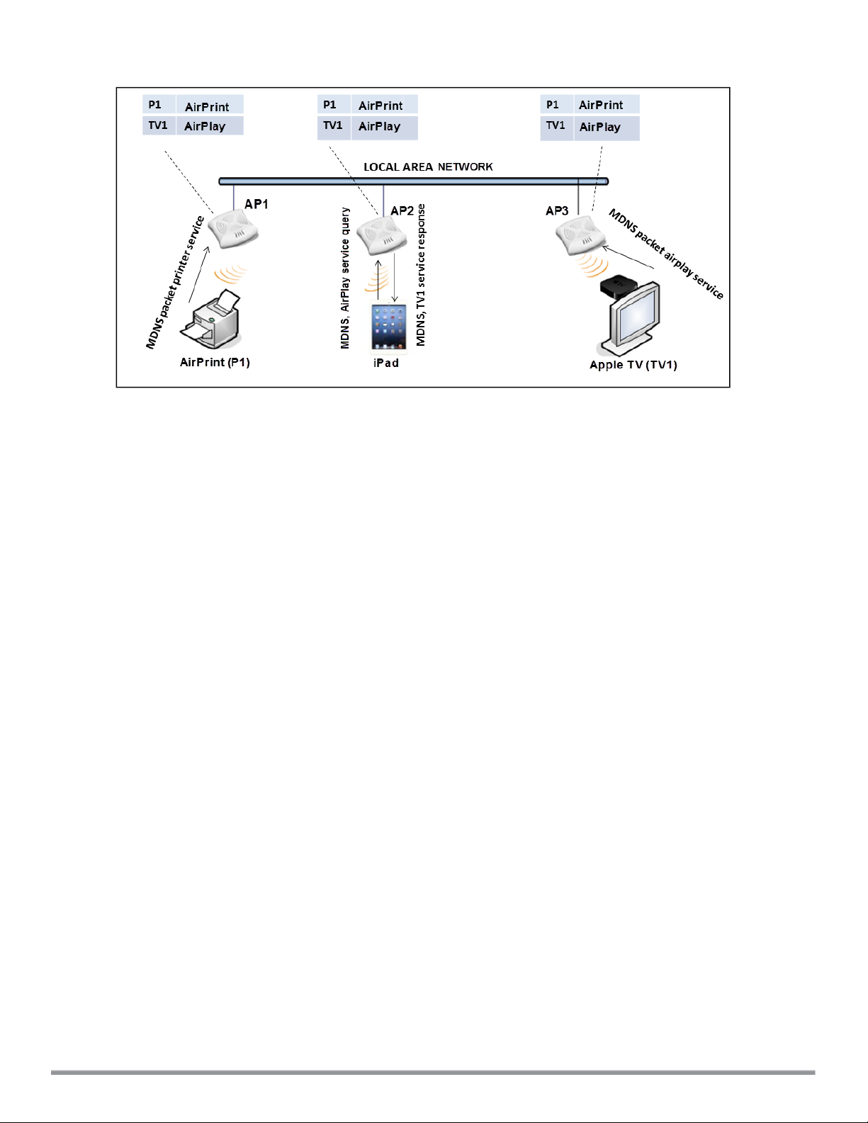
Figure 5: Bonjour support architecture
Bonjour support with Cloud Network Manager
Bonjour support capabilities are available in HP WLANs where Wi-Fi data is transmitted via APs. Bonjour support
is available on an HP WLAN that is managed by Cloud Network Manager.
l The Bonjour support administrator assigns the Bonjour support operator role to an end user, which authorizes
the user to register their device—such as an Apple TV.
l Cloud Network Manager maintains information for all mDNS services.
l Cloud Network Manager responds to device queries based on contextual data such as user role, username, and
location.
Bonjour support solution
In large universities and enterprise networks, it is common for Bonjour-capable devices to connect to the network
across VLANs. As a result, user devices such as an iPad on a specific VLAN cannot discover an Apple TV that
resides on another VLAN. As the addresses used by the protocol are link-scope multicast addresses, each query
or advertisement can only be forwarded on its respective VLAN.
Broadcast and multicast traffic are usually filtered out from a wireless LAN network to preserve airtime and battery
life. This inhibits the performance of Bonjour services as they rely on multicast traffic. HP addresses this mDNS
challenge with Bonjour support technology.
Bonjour support leverages key elements from portfolio of HP including operating system software for Cloud
Network Manager. Bonjour support maintains seamless connectivity between clients and services across VLANs
and SSIDs. The mDNS packet traffic is minimized, thereby preserving valuable wired network bandwidth and
WLAN airtime.
The following list summarizes the filtering options that are integrated with Cloud Network Manager deployment
models:
l Allow mDNS to propagate across subnets/VLANs
l Limit multicast mDNS traffic on the network
l VLAN based mDNS service policy enforcement
l User-role based mDNS service policy enforcement
Bonjour support also enables context awareness for services across the network:
69 | Wireless configuration HP Cloud Network Manager | User Guide
Page 70

l Bonjour support is aware of personal devices. For example, an Apple TV in a dorm room can be associated with
the student who owns it.
l Bonjour support is aware of shared resources.For example, an Apple TV in a meeting room or a printer in a
supply room that is available to certain users, such as the marketing department. Or, in a classroom, teachers
can use AirPlay to wirelessly project a laptop screen onto an HDTV monitor using an Apple TV.
l When configured with Cloud Network Manager, Bonjour support enables a client to perform a location-based
discovery. For example, when a client roams from one Cloud Network Manager cluster to another, it can
discover devices available in the new cluster to which the client is currently connected.
Bonjour support features
Bonjour support provides the following features:
l Send unicast responses to mDNS queries and reduces mDNS traffic footprint.
l Ensure cross-VLAN visibility and availability of mDNS devices and services.
l Allow or block mDNS services for all users.
l Allow or block mDNS services based on user roles.
l Allow or block mDNS services based on VLANs.
Bonjour support services
Bonjour supports zero-configuration services. The services are preconfigured and are available as part of the
factory default configuration. The administrator can also enable or disable any or all services.
The following services are available for AP clients:
l AirPlay — Apple AirPlay allows wireless streaming of music, video, and slideshows from your iOS device to
Apple TV and other devices that support the AirPlay feature.
l AirPrint — Apple AirPrint allows you to print from an iPad, iPhone, or iPod Touch directly to any AirPrint
compatible printer.
l iTunes— The iTunes service is used by iTunes Wi-Fi sync and iTunes home-sharing applications across all
Apple devices.
l RemoteMgmt— Use this service for remote login, remote management, and FTP utilities on Apple devices.
l Sharing— Applications such as disk sharing and file sharing, use the service ID that are part of this service on
one or more Apple devices.
l Chat— The iChat (Instant Messenger) application on Apple devices uses this service.
Configuring Bonjour support and Bonjour support services on an AP
To enable Bonjour support and its services:
1. Select Wireless Configuration > Services > BONJOUR SUPPORT.
2. Select ENABLEBONJOUR SUPPORT. The Bonjour support configuration parameters are displayed.
3. Select ENABLE GUEST BONJOUR MULTICAST to allow the users to use Bonjour support services enabled
in a guest VLAN. However, the Bonjour support devices are visible in the guest VLAN and Bonjour support
does not discover or enforce policies in the guest VLAN.
4. Select ENABLE BONJOUR SUPPORT ACROSS MOBILITY DOMAINS to enable Inter cluster mobility.
Cloud Network Manager supports two types of assignment modes:
l Intra Cluster (checkbox cleared) - The AP does not share the mDNS database information with the other
clusters.
l Inter Cluster (checkbox selected) - The AP shares the mDNS database information with the other clusters.
The DNS records in the VC can be shared with the all the VCs configured for L3 Mobility.
HP Cloud Network Manager | User Guide Wirelessconfiguration | 70
Page 71

5. Select required Bonjour support services. To allow all services, select ALLOWALL.
6. Based on the services configured, you can block any user roles and VLAN from accessing a Bonjour support
service. The user roles and VLANs marked as disallowed are prevented from accessing the
correspondingBonjour support service. You can create a list of disallowed user roles and VLANs for all Bonjour
support services configured on the AP. For example, If the AirPlay service is selected, the Edit links for the
AIRPLAY DISALLOWED ROLES and AIRPLAY DISALLOWED VLANS are displayed. Similarly, if sharing
service is selected, the Edit links for the SHARING DISALLOWED ROLES and SHARING DISALLOWED
VLANS are displayed.
l To block user roles from accessing a Bonjour support service, click the corresponding Edit link and select
the user roles for which you want to restrict access. By default, an Bonjour support service is accessible by
all user roles configured in your AP cluster.
l To select VLANs from allowing access to Bonjour support service, click the corresponding Edit link and
select the VLANs to exclude. By default, the Bonjour support services are accessible by users or devices in
all VLANs configured in your AP cluster.
Integrating an AP with Palo Alto Networks firewall
Palo Alto Networks (PAN) next-generation firewall offers contextual security for all users for safe enabling of
applications. A simple firewall beyond basic IP address or TCP port numbers only provides a subset of the
enhanced security required for enterprises to secure their networks. In the context of businesses using social
networking sites, legacy firewalls are not able to differentiate valid authorized users from casual social networking
users.
The Palo Alto next-generation firewall is based on user ID, which provides many methods for connecting to
sources of identity information and associating them with firewall policy rules. For example, it provides an option to
gather user information from Active Directory or LDAP server.
Integration with Cloud Network Manager
The functionality provided by the PAN firewall based on user ID requires the collection of information from the
network. AP maintains the network (such as mapping IP address) and user information for its clients in the network
and can provide the required information for the user ID feature on PAN firewall. Before sending the user-ID
mapping information to the PAN firewall, the AP must retrieve an API key that is used for authentication for all
APIs.
AP and PAN firewall integration can be seamless with the XML-API that available with PAN-OS 5.0 or later.
To integrate an AP with PAN user ID, a global profile is added. This profile can be configured on an AP with PAN
firewall information such as IP address, port, user name, password, firewall enabled or disabled status.
The AP sends messages to PAN based on the type of authentication and client status:
l After a client completes the authentication and is assigned an IP address, AP sends the login message.
l After a client is disconnected or dissociated from the AP, the AP sends a logout message.
Configuring an AP for PAN integration
To configure an AP for PAN firewall integration:
1. Select Wireless Configuration > Services. The Services pane is displayed.
2. Click NETWORK INTEGRATION. The PAN firewall configuration options are displayed.
3. Select ENABLE to enable PAN firewall.
4. Specify the USERNAME and PASSWORD. Ensure that you provide user credentials of the PAN firewall
administrator.
5. Enter the PAN firewall IP ADDRESS.
71 | Wireless configuration HP Cloud Network Manager | User Guide
Page 72

6. Enter the port number within the range of 1—65535. The default port is 443.
7. Click SaveSettings.
Uplink configuration
This section provides the following information:
l Uplink interfaces on page 72
l Uplink preferences and switching on page 74
Uplink interfaces
Cloud Network Manager supports Wi-Fi uplink to provide access to the corporate network.
The following figure illustrates a scenario in which the APs join the VC as slave APs through a wired or mesh Wi-Fi
uplink.
Figure 6: Uplink types
Cloud Network Manager supports the following types of uplinks:
l Wi-Fi uplink
l Ethernet uplink
Wi-Fi uplink
The Wi-Fi uplink is supported for all AP models, but only the master AP uses this uplink. The Wi-Fi allows uplink to
open, PSK-CCMP, and PSK-TKIP SSIDs.
l For single radio APs, the radio serves wireless clients and Wi-Fi uplink.
l For dual radio APs, both radios can be used to serve clients but only one of them can be used for Wi-Fi uplink.
When Wi-Fi uplink is in use, the client IP is assigned by the internal DHCP server.
Configuring a Wi-Fi uplink profile
The following configuration conditions apply to the Wi-Fi uplink:
l To bind or unbind the Wi-Fi uplink on the 5 GHz band, reboot the AP.
l If Wi-Fi uplink is used on the 5 GHz band, mesh is disabled. The two links are mutually exclusive.
To provision an AP with Wi-Fi Uplink, complete the following steps:
HP Cloud Network Manager | User Guide Wirelessconfiguration | 72
Page 73

1. If you are configuring a Wi-Fi uplink after restoring factory settings on an AP, connect the AP to an Ethernet
cable to allow the AP to get the IP address. Otherwise, go to step 2.
2. Select Wireless Configuration > System. The System details are displayed.
3. Select UPLINK and under WiFi, enter the name of the wireless network that is used for Wi-Fi uplink in the
NAME (SSID) box.
4. From MANAGEMENT, select the type of key for uplink encryption and authentication. If the uplink wireless
router uses mixed encryption, WPA-2 is recommended for Wi-Fi uplink.
5. From BAND, select the band in which the VC currently operates. The following options are available:
l 2.4 GHz (default)
l 5 GHz
6. From PASSPHRASE FORMAT, select a Passphrase format. The following options are available:
l 8 - 63 alphanumeric characters
l 64 hexadecimal characters
Ensure that the hexadecimal password string is exactly 64 digits in length.
7. Enter a pre-shared key (PSK) passphrase in PASSPHRASE and click OK.
Ethernet uplink
The Ethernet 0 port on anAP is enabled as an uplink port by default.
Ethernet uplink supports the following:
n PPPoE
n DHCP
n Static IP
You can use PPPoE for your uplink connectivity in a single AP deployment.
Uplink redundancy with the PPPoE link is not supported.
When the Ethernet link is up, it is used as a PPPoE or DHCP uplink. After the PPPoE settings are configured,
PPPoE has the highest priority for the uplink connections. The AP can establish a PPPoE session with a PPPoE
server at the ISP and get authenticated using PAP or the CHAP. Depending upon the request from the PPPoE
server, either the PAP or the CHAP credentials are used for authentication. After configuring PPPoE, reboot the
AP for the configuration to take effect. The PPPoE connection is dialed after the AP comes up. The PPPoE
configuration is checked during AP boot and if the configuration is correct, Ethernet is used for the uplink
connection.
When PPPoE is used, do not configure Dynamic RADIUS Proxy and IP address of the VC. An SSID created with default
VLAN is not supported with PPPoE uplink.
You can also configure an alternate Ethernet uplink to enable uplink failover when an Ethernet port fails.
Configuring PPPoE uplink profile
To configure PPPOE settings:
1. Select Wireless Configuration > System. The System details are displayed.
73 | Wireless configuration HP Cloud Network Manager | User Guide
Page 74

2. Select UPLINK, perform the following steps in the PPPoE pane:
a. Enter the PPPoE service name provided by your service provider in SERVICENAME.
b. In the CHAP SECRET and RETYPE CHAPSECRET fields, enter the secret key used for CHAP
authentication. You can use a maximum of 34 characters for the CHAP secret key.
c. Enter the user name for the PPPoE connection in the USER field.
d. In the PASSWORD and RETYPE PASSWORD fields, enter a password for the PPPoE connection and
confirm it.
3. To set a local interface for the PPPoE uplink connections, select a value from LOCAL INTERFACE. The
selected DHCP scope is used as a local interface on the PPPoE interface and the Local, L3 DHCP gateway IP
address as its local IP address. When configured, the local interface acts as an unnumbered PPPoE interface
and and allocated the entire Local, L3 DHCP subnet to the clients.
The options in LOCAL INTERFACE are displayed only if a Local, L3 DHCP scope is configured on the AP.
4. Click Save Settings.
5. Reboot the AP.
Uplink preferences and switching
This topic describes the following procedures:
l Enforcing uplinks on page 74
l Setting an uplink priority on page 74
l Enabling uplink pre-emption on page 75
Enforcing uplinks
The following configuration conditions apply to the uplink enforcement:
l When an uplink is enforced, the AP uses the specified uplink regardless of uplink pre-emption configuration and
the current uplink status.
l When an uplink is enforced and multiple Ethernet ports are configured and uplink is enabled on the wired
profiles, the AP tries to find an alternate Ethernet link based on the priority configured.
l When no uplink is enforced and pre-emption is not enabled, and if the current uplink fails, the AP tries to find an
available uplink based on the priority configured.
l When no uplink is enforced and pre-emption is enabled, and if the current uplink fails, the AP tries to find an
available uplink based on the priority configured. If current uplink is active, the AP periodically tries to use a
higher priority uplink and switches to the higher priority uplink even if the current uplink is active.
To enforce a specific uplink on an AP:
1. Select Wireless Configuration > System > UPLINK. The Uplink details are displayed.
2. Under Management, select the type of uplink from ENFORCE UPLINK. If Ethernet uplink is selected, the
Port field is displayed.
3. Specify the Ethernet interface port number.
4. Click OK. The selected uplink is enforced on the AP.
Setting an uplink priority
To set an uplink priority:
1. Select Wireless Configuration > System > UPLINK. The Uplink details are displayed.
HP Cloud Network Manager | User Guide Wirelessconfiguration | 74
Page 75

2. Under UPLINK PRIORITY LIST, select the uplink, and increase or decrease the priority. By default, the Eth0
uplink is set as a high priority uplink.
3. Click OK. The selected uplink is prioritized over other uplinks.
Enabling uplink pre-emption
The following configuration conditions apply to uplink pre-emption:
l Pre-emption can be enabled only when no uplink is enforced.
l When pre-emption is disabled and the current uplink fails, the AP tries to find an available uplink based on the
uplink priority configuration.
l When pre-emption is enabled and if the current uplink is active, the AP periodically tries to use a higher priority
uplink, and switches to a higher priority uplink even if the current uplink is active.
To enable uplink pre-emption:
1. Select Wireless Configuration > System > Uplink. The Uplink details are displayed.
2. Under MANAGEMENT, ensure that the ENFORCEUPLINK is set to None.
3. From PRE-EMPTION, select Enabled.
4. Click OK.
Switching uplinks based on internet availability
You can configure Cloud Network Manager to switch uplinks based on internet availability.
When the uplink switchover based on internet availability is enabled, the AP continuously sends ICMP packets to
some well-known internet servers. If the request is timed out due to a bad uplink connection or uplink interface
failure, and the internet is not reachable from the current uplink, the AP switches to a different connection.
To configure uplink switching:
1. Select Wireless Configuration > System > UPLINK. The Uplink details are displayed.
2. Under Management, configure:
l INTERNETFAILOVER — To configure uplink switching based on Internet availability, perform the following
steps:
a. Select Enabled from INTERNETFAILOVER.
b. Specify values for FAILOVER INTERNET PACKET SEND FREQUENCY, FAILOVER
INTERNET PACKET LOST COUNT, and INTERNET CHECK COUNT,
c. Click OK.
Mobility and client management
This section provides the following information:
l Layer-3 mobility overview on page 75
l Configuring L3-mobility on page 76
Layer-3 mobility overview
APs form a single Cloud Network Manager network when they are in the same Layer-2 (L2) domain. As the number
of clients increase, multiple subnets are required to avoid broadcast overhead. In such a scenario, a client must be
allowed to roam away from the Cloud Network Manager network to which it first connected (home network) to
another network supporting the same WLAN access parameters (foreign network) and continue its existing
sessions.
75 | Wireless configuration HP Cloud Network Manager | User Guide
Page 76

Layer-3 (L3) mobility allows a client to roam without losing its IP address and sessions. If WLAN access
parameters are the same across these networks, clients connected to APs in a given Cloud Network Manager
network can roam to APs in a foreign Cloud Network Manager network and continue their existing sessions using
their IP addresses. You can configure a list of Virtual Controller IP addresses across which L3 mobility is
supported.
The HP Cloud Network Manager Layer-3 mobility solution defines a Mobility Domain as a set networks, with the
same WLAN access parameters, across which client roaming is supported. The Cloud Network Manager network
to which the client first connects is called its home network. When the client roams to a foreign network, an AP in
the home network (home AP) anchors all traffic to or from this client. The AP to which the client is connected in the
foreign network (foreign AP) tunnels all client traffic to or from the home AP through a GRE tunnel.
Figure 7: Routing of traffic when the client is away from its home network
When a client first connects to Cloud Network Manager network, a message is sent to all configured Virtual
Controller IP addresses to see if this is an L3 roamed client. On receiving an acknowledgment from any of the
configured Virtual Controller IP addresses, the client is identified as an L3 roamed client. If the AP has no GRE
tunnel to this home network, a new tunnel is formed to an AP (home AP) from the home network of the client.
Each foreign AP has only one home AP per Cloud Network Manager network to avoid duplication of broadcast
traffic. Separate GRE tunnels are created for each foreign AP / home AP pair. If a peer AP is a foreign AP for one
client and a home AP for another, two separate GRE tunnels are used to handle L3 roaming traffic between these
APs.
If client subnet discovery fails on association due to some reason, the foreign AP identifies its subnet when it
sends out the first L3 packet. If the subnet is not a local subnet and belongs to another network, the client is treated
as an L3 roamed client and all its traffic is forwarded to the home network through a GRE tunnel.
Configuring L3-mobility
To configure a mobility domain, you have to specify the list of all Cloud Network Manager networks that form the
mobility domain. To allow clients to roam seamlessly among all the APs, specify the VC IP for each foreign
subnet. You may include the local Cloud Network Manager or VC IP address, so that the same configuration can
be used across all Cloud Network Manager networks in the mobility domain.
HP Cloud Network Manager | User Guide Wirelessconfiguration | 76
Page 77

It is recommended that you configure all client subnets in the mobility domain. When client subnets are configured:
l If a client is from a local subnet, it is identified as a local client. When a local client starts using the IP address,
the L3 roaming is terminated.
l If the client is from a foreign subnet, it is identified as a foreign client. When a foreign client starts using the IP
address, the L3 roaming is set up.
Home agent load balancing
Home Agent Load Balancing is required in large networks where multiple tunnels might terminate on a single border
or lobby AP and overload it. When load balancing is enabled, the VC assigns the home AP for roamed clients by
using a round robin policy. With this policy, the load for the APs acting as Home Agents for roamed clients is
uniformly distributed across the AP cluster.
Configuring L3 mobility domain
To configure L3 mobility domain:
1. Select Wireless Configuration > System. The System details are displayed.
2. Select L3 MOBILITY. The L3 Mobility details are displayed.
3. From HOME AGENT LOAD BALANCING, select Enabled. By default, home agent load balancing is
disabled.
4. Click New in VIRTUAL CONTROLLER IP ADDRESSES, add the IP address of a VC that is part of the
mobility domain, and click Ok.
5. Repeat Step 2 to add the IP addresses of all VCs that form the L3 mobility domain.
6. Click New in SUBNETS and specify the following:
a. Enter the client subnet in the IP ADDRESS box.
b. Enter the mask in the SUBNET MASK box.
c. Enter the VLAN ID in the home network in the VLAN ID box.
d. Enter the home VC IP address for this subnet in the VIRTUAL CONTROLLER IP box.
7. Click Ok.
Enterprise domain
The enterprise domain names list displays the DNS domain names that are valid on the enterprise network. This
list is used to determine how client DNS requests are routed. When Content Filtering is enabled, the DNS request
of the clients is verified and the domain names that do not match the names in the list are sent to the openDNS
server.
Configuring enterprise domains
To configure an enterprise domain:
1. Select Wireless Configuration > System, click ENTERPRISE DOMAINS. The ENTERPRISE DOMAINS
details are displayed.
2. Click New and enter a name in the NEW DOMAIN NAME.
3. Click Ok.
To remove a domain, select the domain and click Delete.
SNMP and logging
This section provides the following information:
77 | Wireless configuration HP Cloud Network Manager | User Guide
Page 78

l Configuring SNMP on page 78
l Configuring a syslog server on page 79
l Configuring TFTP dump server on page 80
Configuring SNMP
This section provides the following information:
l SNMP parameters for AP on page 78
l Configuring community string for SNMP on page 78
l Configuring SNMP traps on page 79
SNMP parameters for AP
Cloud Network Manager supports SNMPv1, SNMPv2c, and SNMPv3 for reporting purposes only. An AP cannot
use SNMP to set values in HP system.
You can configure the following parameters for an AP:
Table 29: SNMP parameters for AP
Data pane item Description
Community Strings for SNMPV1
and SNMPV2
An SNMP community string is a text string that acts as a password,
and is used to authenticate messages sent between the VC and the
SNMP agent.
If you are using SNMPv3 to obtain values fromthe AP, you can configure the following parameters:
Name A string representing the name of the user.
Authentication Protocol An indication of messages sent on behalf of this user can be
authenticated, and if so, the type of authentication protocol used.
Specify one of the following values:
l MD5— HMAC-MD5-96 Digest Authentication Protocol
l SHA: HMAC-SHA-96 Digest Authentication Protocol
Authentication protocol
password
If messages sent on behalf of this user can be authenticated, the
(private) authentication key is used with the authentication protocol.
This is a string password for MD5 or SHA depending on the choice
above.
Privacy protocol An indication of messages sent on behalf of this user can be
protected from disclosure, and if yes, the type of privacy protocol
which is used. This takes the value DES (CBC-DES Symmetric
Encryption).
Privacy protocol password If messages sent on behalf of this user can be encrypted/decrypted
with DES, the (private) privacy key is used with the privacy protocol.
Configuring community string for SNMP
This section describes the procedure for configuring SNMPv1, SNMPv2, and SNMPv3 community strings using
the Cloud Network Manager.
Creating community strings for SNMPv1 and SNMPv2
To create community strings for SNMPv1 and SNMPv2:
HP Cloud Network Manager | User Guide Wirelessconfiguration | 78
Page 79

1. Select Wireless Configuration > System. The System details are displayed.
2. Click the SNMP tab, and then click New under COMMUNITY STRINGS.
3. Enter the string in SNMP.
4. Click Ok.
5. To delete a community string, select the string, and click Delete.
Creating community strings for SNMPv3
To create community strings for SNMPv3:
1. Select Wireless Configuration > System. The System details are displayed.
2. Click the SNMP tab. The SNMP configuration parameters are displayed.
3. Click New in the Users for SNMPV3 box. A pane for specifying SNMPv3 user information is displayed.
4. Enter the name of the user in the NAME box.
5. From AUTH PROTOCOL, select the type of authentication protocol.
6. Enter the authentication password in the PASSWORD box and retype the password in the RETYPE
PASSWORD box.
7. From PRIVACY PROTOCOL, select the type of privacy protocol.
8. Enter the privacy protocol password in the Password box and retype the password in the RETYPE
PASSWORD box.
9. Click Ok.
10.To edit the details for a user, select the user and click Edit.
11.To delete a user, select the user and click Delete.
Configuring SNMP traps
Cloud Network Manager supports the configuration of external trap receivers. Only the AP acting as the VC
generates traps. The Object Identifier (OID) of the traps is 1.3.6.1.4.1.14823.2.3.3.1.200.2.X.
To configure SNMP traps:
1. Select Wireless Configuration > System > SNMP. The SNMP details are displayed.
2. Under SNMP TRAPS, click New and update the following fields:
l IP ADDRESS — Enter the IP Address of the new SNMP Trap receiver.
l VERSION — Select the SNMP version. The version specifies the format of traps generated by the AP.
l COMMUNITY/USERNAME — Specify the community string for SNMPv1 and SNMPv2c traps and a
username for SNMPv3 traps.
l PORT— Enter the port number to which the traps are sent. The default value is 162.
l INFORM — When enabled, SNMPv3 traps are sent as SNMP INFORM messages. It is applicable to
SNMPv3 only. The default value is Yes.
3. Click Ok.
Configuring a syslog server
To specify a syslog server for sending syslog messages to the external servers:
1. Select Wireless Configuration > System. The System details are displayed.
2. Select the LOGGING tab.
3. In the SYSLOG SERVER box, enter the IP address of the server to which you want to send system logs.
79 | Wireless configuration HP Cloud Network Manager | User Guide
Page 80

4. Select the required values to configure Syslog Facility Levels. Syslog facility is an information field associated
with a syslog message. It is an application or operating system component that generates a log message. The
following facilities are supported by syslog:
l AP-DEBUG— Detailed log about the AP device.
l NETWORK— Log about change of network, for example, when a new AP is added to a network.
l SECURITY— Log about network security, for example, when a client connects using wrong password.
l SYSTEM— Log about configuration and system status.
l USER— Important logs about client.
l USER-DEBUG— Detailed log about client.
l WIRELESS— Log about radio.
The following table describes the logging levels in order of severity, from the most to the least severe.
Table 30: Logging levels
Logging level Description
Emergency Panic conditions that occur when the system becomes unusable.
Alert Any condition requiring immediate attention and correction.
Critical Any critical condition such as a hard drive error.
Error Error conditions.
Warning Warning messages.
Notice Significant events of a non-critical nature. The default value for all syslog
facilities.
Information Messages of general interest to system users.
Debug Messages containing information useful for debugging.
5. Click Save Settings.
Configuring TFTP dump server
To configure a TFTP server for storing core dump files:
1. Select Wireless Configuration > System > LOGGING.
2. Enter the IP address of the TFTP server in the TFTP DUMP SERVER box.
3. Click Save Settings.
HP Cloud Network Manager | User Guide Wirelessconfiguration | 80
Page 81

Reports
The Reports tab displays the summary of the reports generated for networks, security, and PCI Compliance.
Figure 8: Reports pane
Overview
The following table displays the parameters that are used to generate a report.
Table 31: Contents of the reporting pane
Data pane item Description
TITLE Displays the title name of the report generated.
DATERUN Displays the date on which report was generated.
SAVEDBY Indicates the user login name using which the report was
generated.
STATUS Displays the current status of the report generated.
ACTIONS
SCHEDULEDTYPE
Allows to either export the report locally or send to an email
address.
Indicates when the report is triggered.
Creating a report
To create a report:
1. Select Reports > Network or Security or PCI Compliance and then click Create New Report. The
CREATENEWREPORT page is displayed.
2. Select the period for which you want to view the report from TIME SPAN.
3. Select Now from RUN REPORT to generate report for the current period.
4. Select how often you want to generate the report by choosing One Time, Daily Interval, Weekly Interval,
Monthly Interval, or Yearly Interval from REPEAT.
5. To send the report through email, select EMAIL REPORT, enter email address, and then click Create.
HP Cloud Network Manager | User Guide Reports | 81
Page 82

Deleting a report
To delete a report:
1. Select Reports > Network or Security or PCI Compliance and then select the report that you want to delete.
2. Click Delete.
82 | Reports HP Cloud Networ k Manager | User Guide
Page 83

Maintenance
The Maintenance tab displays the maintenance pane for the Cloud Network Manager.
Figure 9: Maintenance pane
The maintenance pane consists of:
l Firmware
l Subscription keys
l Device management
l User management
Firmware
The Firmware tab provides an overview of the latest supported version of AP, details of the AP, and the option to
upgrade an AP .
Table 32: Contents of the firmware pane
Data pane item Description
LATESTSUPPORTEDVERSION Displays the latest firmware version available on the public
firmware server.
VIRTUALCONTROLLERS Displays the following information:
l VC Name
l APs
l LOCATION
l FIRMWARE VERSION
l STATUS
UPGRADEFIRMWARE Allows you to upgrade the firmware of the selected VC to the
latest supported version.
Subscription keys
The Subscription Keys tab provides details of the licenses assigned to an AP.
HP Cloud Network Manager | User Guide Maintenance | 83
Page 84

Table 33: Contents of the licenses pane
Data pane item Description
NAME Displays the name of the license.
STARTDATE Displays when the license is assigned to your AP.
ENDDATE Displays the license expiry date.
CAPACITY Displays the maximum capacity of the license.
APs USED Displays the number of APs that use a license.
Device management
The Device Management tab provides details of an AP.
Table 34: Contents of the device management pane
Data pane item Description
SERIAL NUMBER Displays the serial number of the AP.
MAC ADDRESS Displays the MAC address of the AP.
SUBSCRIPTION KEY
STARTDATE
ENDDATE
Displays the license of the AP.
Displays the start date of the license.
Displays the expiry date of the license.
User management
The User Management tab provides details of the user such as username, user scope, access level, and actions
such as edit or delete. It also allows you to configure user credentials that enable access to the Cloud Network
Manager UI.
The user can perform following actions:
l Add User: Add additional users to the Network Management System (NMS).
l SupportAccess On: Allows HP support to access your Cloud Network Manager account remotely.
84 | Maintenance HP Cloud Network Manager | User Guide
Page 85

Terminology
Acronyms and abbreviations
The following table lists the abbreviations in this user guide.
Table 35: List of abbreviations
Abbreviation Expansion
AP Access Point
ARRM Advanced Radio Resource Management
ARP Address Resolution Protocol
BSS Basic Server Set
BSSID Basic Server Set Identifier
CA Certification Authority
CLI Command Line Interface
DHCP Dynamic Host Configuration Protocol
DMZ Demilitarized Zone
DNS Domain Name System
EAP-TLS Extensible Authentication Protocol-Transport Layer Security
EAP-TTLS Extensible Authentication Protocol-Tunneled Transport
Layer Security
IDS Intrusion Detection System
IEEE Institute of Electrical and Electronics Engineers
ISP Internet Service Provider
LEAP Lightweight Extensible Authentication Protocol
MAC Media Access Control
MX Mail Exchanger
NAS Network Access Server
NAT Network Address Translation
NS Name Server
HP Cloud Network Manager | User Guide Terminology | 85
Page 86

Table 35: List of abbreviations
Abbreviation Expansion
NTP Network Time Protocol
PEAP Protected Extensible Authentication Protocol
PEM Privacy Enhanced Mail
PoE Power over Ethernet
RADIUS Remote Authentication Dial In User Service
VC Virtual Controller
VSA Vendor-Specific Attributes
WLAN Wireless Local Area Network
Glossary
The following table lists the terms and their definitions in this guide.
Table 36: List of terms
Term Definit ion
802.11 An evolving family of specifications for wireless LANs developed by a
working group of the Institute of Electrical and Electronics Engineers
(IEEE). 802.11 standards use the Ethernet protocol and CSMA/CA (carrier
sense multiple access with collision avoidance) for path sharing.
802.11a Provides specifications for wireless systems. Networks using 802.11a
operate at radio frequencies in the 5GHz band. The specification uses a
modulation scheme known as orthogonal frequency-division multiplexing
(OFDM) that is especially well suited to use in office settings. The
maximum data transfer rate is 54 Mbps.
802.11b WLAN standard often called Wi-Fi; backward compatible with 802.11.
Instead of the phase-shift keying (PSK) modulation method historically
used in 802.11 standards, 802.11b uses complementary code keying
(CCK), which allows higher data speeds and is less susceptible to
multipath-propagation interference. 802.11b operates in the 2.4 GHz band
and the maximum data transfer rate is 11 Mbps.
802.11g Offers transmission over relatively short distances at up to 54 Mbps,
compared with the 11 Mbps theoretical maximum of 802.11b. 802.11g
operates in the 2.4 GHz band and employs orthogonal frequency division
multiplexing (OFDM), the modulation scheme used in 802.11a, to obtain
higher data speed. Computers or terminals set up for 802.11g can fall
back to speeds of 11 Mbps, so that 802.11b and 802.11g devices can be
compatible within a single network.
802.11n Wireless networking standard to improve network throughput over the two
previous standards 802.11a and 802.11g with a significant increase in the
maximum raw data rate from 54 Mbps to 600 Mbps with the use of four
spatial streams at a channel width of 40 MHz. 802.11n operates in the 2.4
and 5.0 bands.
86 | Terminology HP Cloud Network Manager | User Guide
Page 87

Table 36: List of terms
Term Definit ion
access point An access point (AP) connects users to other users within the network and
also can serve as the point of interconnection between the WLAN and a
fixed wire network. The number of APs a WLAN needs is determined by
the number of users and the size of the network.
access point mapping The act of locating and possibly exploiting connections to WLANs while
driving around a city or elsewhere. To do war driving, you need a vehicle,
a computer (which can be a laptop), a wireless Ethernet card set to work in
promiscuous mode, and some kind of an antenna which can be mounted
on top of or positioned inside the car. Because a WLAN may have a range
that extends beyond an office building, an outside user may be able to
intrude into the network, obtain a free internet connection, and possibly
gain access to company records and other resources.
ad-hoc network A LAN or other small network, especially one with wireless or temporary
plug-in connections, in which some of the network devices are part of the
network only for the duration of a communications session or, in the case
of mobile or portable devices, while in some close proximity to the rest of
the network.
band A specified range of frequencies of electromagnetic radiation.
DHCP The Dynamic Host Configuration Protocol (DHCP) is an auto-configuration
protocol used on IP networks. Computers or any network peripherals that
are connected to IP networks must be configured, before they can
communicate with other computers on the network. DHCP allows a
computer to be configured automatically, eliminating the need for a
network administrator. DHCP also provides a central database to
keep track of computers connected to the network. This database helps in
preventing any two computers from being configured with the same IP
address.
DNS Server A Domain Name System (DNS) server functions as a phonebook for the
internet and internet users. It converts human readable computer
hostnames into IP addresses and vice-versa.
A DNS server stores several records for a domain name such as an
address 'A' record, name server (NS), and mail exchanger (MX) records.
The Address 'A' record is the most important record that is stored in a DNS
server, because it provides the required IP address for a network
peripheral or element.
DST Daylight saving time (DST), also known as summer time, is the practice of
advancing clocks, so that evenings have more daylight and mornings
have less. Typically clocks are adjusted forward one hour near the start of
spring and are adjusted backward in autumn.
EAP Extensible authentication protocol (EAP) refers to the authentication
protocol in wireless networks that expands on methods used by the pointto-point protocol (PPP), a protocol often used when connecting a
computer to the internet. EAP can support multiple authentication
mechanisms, such as token cards, smart cards, certificates, one-time
passwords, and public key encryption authentication.
fixed wireless Wireless devices or systems in fixed locations such as homes and offices.
Fixed wireless devices usually derive their electrical power from the utility
mains, unlike mobile wireless or portable wireless which tend to be
HP Cloud Network Manager | User Guide Terminology | 87
Page 88

Table 36: List of terms
Term Definit ion
battery-powered. Although mobile and portable systems can be used in
fixed locations, efficiency and bandwidth are compromised compared with
fixed systems.
frequency allocation Use of radio frequency spectrum regulated by governments.
frequency spectrum Part of the electromagnetic spectrum.
hotspot A WLAN node that provides internet connection from a given location. A
business traveler, for example, with a laptop equipped for Wi-Fi can look
up a local hot spot, contact it, and get connected through its network to
reach the internet and their own company remotely with a secure
connection. Increasingly, public places, such as airports, hotels, and
coffee shops are providing free wireless access for customers.
IEEE 802.11 standards The IEEE 802.11 is a set of standards that are categorized based on the
radio wave frequency and the data transfer rate.
POE Power over Ethernet (PoE) is a method of delivering power on the same
physical Ethernet wire used for data communication. Power for devices is
provided in one of the following two ways:
l Endspan— The switch that an AP is connected for power supply.
l Midspan— A device can sit between the switch and APs
The choice of endspan or midspan depends on the capabilities of the
switch to which the AP is connected. Typically if a switch is in place and
does not support PoE, midspan power injectors are used.
PPPoE Point-to-Point Protocol over Ethernet (PPPoE) is a method of connecting
to the internet typically used with DSL services where the client connects
to the DSL modem.
QoS Quality of Service (QoS) refers to the capability of a network to provide
better service to a specific network traffic over various technologies.
RF Radio Frequency (RF) refers to the portion of electromagnetic spectrum in
which electromagnetic waves are generated by feeding alternating current
to an antenna.
Wi-Fi A term for certain types of WLANs. Wi-Fi can apply to products that use
any 802.11 standard. Wi-Fi has gained acceptance in many businesses,
agencies, schools, and homes as an alternative to a wired LAN. Many
airports, hotels, and fast-food facilities offer public access to Wi-Fi
networks.
wired equivalent privacy (WEP) Wired equivalent privacy (WEP) is a security protocol specified in 802.11b,
designed to provide a WLAN with a level of security and privacy
comparable to what is usually expected of a wired LAN. Data encryption
protects the vulnerable wireless link between clients and APs; once this
measure has been taken, other typical LAN security mechanisms such as
password protection, end-to-end encryption, and authentication can be
put in place to ensure privacy.
wireless Describes telecommunications in which electromagnetic waves (rather
than some form of wire) carry the signal over part or all of the
communication path.
88 | Terminology HP Cloud Network Manager | User Guide
Page 89

Table 36: List of terms
Term Definit ion
wireless network In a Wireless LAN (WLAN), laptops, desktops, PDAs, and other computer
peripherals are connected to each other without any network cables.
These network elements or clients use radio signals to communicate with
each other. Wireless networks are set up based on the IEEE 802.11
standards.
wireless ISP (WISP) Wireless ISP (WISP) refers to an internet service provider (ISP) that allows
subscribers to connect to a server at designated hot spots (APs) using a
wireless connection such as Wi-Fi. This type of ISP offers broadband
service and allows subscriber computers, called stations, to access the
internet and the web from anywhere within the zone of coverage provided
by the server antenna, usually a region with a radius of several kilometers.
wireless service provider A company that offers transmission services to users of wireless devices
through radio frequency (RF) signals rather than through end-to-end wire
communication.
WLAN Wireless LAN (WLAN) is a local area network (LAN) that the users access
through a wireless connection.
HP Cloud Network Manager | User Guide Terminology | 89
 Loading...