


HPE Cloudline CL2100 / CL2200 Gen10
Abstract
This document is for the person who installs, administers, services, and troubleshoots servers. This guide describes identification and
maintenance procedures, and specifications and requirements for hardware components and software. Hewlett Packard Enterprise
assumes you are qualified in the servicing of computer equipment, trained in recognizing hazards in products, and are familiar with weight
and stability precautions.
Server
Troubleshooting Guide
Part Number: P04906-001a
December 2017
Edition: 1

© Copyright 2017 Hewlett Packard Enterprise Development LP
The information contained herein is subject to change without notice. The only warranties for Hewlett Packard Enterprise products and services
are set forth in the express warranty statements accompanying such products and services. Nothing herein should be construed as constituting
an additional warranty. Hewlett Packard Enterprise shall not be liable for technical or editorial errors or omissions contained herein.
Links to third-party websites take you outside the Hewlett Packard Enterprise website. Hewlett Packard Enterprise has no control over and is not
responsible for information outside the Hewlett Packard Enterprise website.
Microsoft®, Windows®, and Windows Server® are either registered trademarks or trademarks of Microsoft Corporation in the United States
and/or other countries. Intel® and Xeon® are trademarks of Intel Corporation in the U.S. and other countries.

Chapter 1 BIOS POST / Beep Code
1-1 BIOS POST Code
PEI_CORE_STARTED
0x10
PEI_CAR_CPU_INIT
0x11
// reserved for CPU 0x12 - 0x14
PEI_CAR_NB_INIT
0x15
// reserved for NB 0x16 - 0x18
PEI_CAR_SB_INIT
0x19
// reserved for SB 0x1A - 0x1C
PEI_MEMORY_SPD_READ
0x1D
PEI_MEMORY_PRESENCE_DETECT
0x1E
PEI_MEMORY_TIMING
0x1F
PEI_MEMORY_CONFIGURING
0x20
PEI_MEMORY_INIT
0x21
// reserved for OEM use: 0x22 - 0x2F
// reserved for AML use: 0x30
PEI_MEMORY_INSTALLED
0x31
PEI_CPU_INIT
0x32
PEI_CPU_CACHE_INIT
0x33
PEI_CPU_BSP_SELECT
0x34
PEI_CPU_AP_INIT
0x35
PEI_CPU_SMM_INIT
0x36
PEI_MEM_NB_INIT
0x37
// reserved for NB 0x38 - 0x3A
PEI_MEM_SB_INIT
0x3B
// reserved for SB 0x3C - 0x3E
// reserved for OEM use: 0x3F - 0x4E
PEI_DXE_IPL_STARTED
0x4F
//Recovery
PEI_RECOVERY_AUTO
0xF0
PEI_RECOVERY_USER
0xF1
PEI_RECOVERY_STARTED
0xF2
PEI_RECOVERY_CAPSULE_FOUND
0xF3
PEI_RECOVERY_CAPSULE_LOADED
0xF4
//S3
PEI_S3_STARTED
0xE0

PEI_S3_BOOT_SCRIPT
0xE1
PEI_S3_VIDEO_REPOST
0xE2
PEI_S3_OS_WAKE
0xE3
//DXE_STATUS_CODE
DXE_CORE_STARTED
0x60
DXE_NVRAM_INIT
0x61
DXE_SBRUN_INIT
0x62
DXE_CPU_INIT
0x63
//reserved for CPU 0x64 - 0x67
DXE_NB_HB_INIT
0x68
DXE_NB_INIT
0x69
DXE_NB_SMM_INIT
0x6A
//reserved for NB 0x6B - 0x6F
DXE_SB_INIT
0x70
DXE_SB_SMM_INIT
0x71
DXE_SB_DEVICES_INIT
0x72
//reserved for SB 0x73 - 0x77
DXE_ACPI_INIT
0x78
DXE_CSM_INIT
0x79
//reserved for AMI use: 0x7A - 0x7F
//reserved for OEM use: 0x80 - 0x8F
DXE_BDS_STARTED
0x90
DXE_BDS_CONNECT_DRIVERS
0x91
DXE_PCI_BUS_BEGIN
0x92
DXE_PCI_BUS_HPC_INIT
0x93
DXE_PCI_BUS_ENUM
0x94
DXE_PCI_BUS_REQUEST_RESOURCES
0x95
DXE_PCI_BUS_ASSIGN_RESOURCES
0x96
DXE_CON_OUT_CONNECT
0x97
DXE_CON_IN_CONNECT
0x98
DXE_SIO_INIT
0x99
DXE_USB_BEGIN
0x9A
DXE_USB_RESET
0x9B
DXE_USB_DETECT
0x9C
DXE_USB_ENABLE
0x9D
//reserved for AMI use: 0x9E - 0x9F
//reserved for AML use: 0xA0
DXE_IDE_BEGIN
0xA1

DXE_IDE_RESET
0xA2
DXE_IDE_DETECT
0xA3
DXE_IDE_ENABLE
0xA4
DXE_SCSI_BEGIN
0xA5
DXE_SCSI_RESET
0xA6
DXE_SCSI_DETECT
0xA7
DXE_SCSI_ENABLE
0xA8
DXE_SETUP_VERIFYING_PASSWORD
0xA9
//reserved for AML use: 0xAA
DXE_SETUP_START
0xAB
DXE_SETUP_INPUT_WAIT
0xAC
DXE_READY_TO_BOOT
0xAD
DXE_LEGACY_BOOT
0xAE
DXE_EXIT_BOOT_SERVICES
0xAF
RT_SET_VIRTUAL_ADDRESS_MAP_BEGIN
0xB0
RT_SET_VIRTUAL_ADDRESS_MAP_END
0xB1
DXE_LEGACY_OPROM_INIT
0xB2
DXE_RESET_SYSTEM
0xB3
DXE_USB_HOTPLUG
0xB4
DXE_PCI_BUS_HOTPLUG
0xB5
DXE_NVRAM_CLEANUP
0xB6
DXE_CONFIGURATION_RESET
0xB7
//reserved for AMI use: 0xB8 - 0xBF
//reserved for OEM use: 0xC0 - 0xCF
//PEI_STATUS_CODE
//Errors
//Regular boot
PEI_MEMORY_INVALID_TYPE
0x50
PEI_MEMORY_INVALID_SPEED
0x50
PEI_MEMORY_SPD_FAIL
0x51
PEI_MEMORY_INVALID_SIZE
0x52
PEI_MEMORY_MISMATCH
0x52
PEI_MEMORY_NOT_DETECTED
0x53
PEI_MEMORY_NONE_USEFUL
0x53
PEI_MEMORY_ERROR
0x54
PEI_MEMORY_NOT_INSTALLED
0x55
PEI_CPU_INVALID_TYPE
0x56
PEI_CPU_INVALID_SPEED
0x56

PEI_CPU_MISMATCH
0x57
PEI_CPU_SELF_TEST_FAILED
0x58
PEI_CPU_CACHE_ERROR
0x58
PEI_CPU_MICROCODE_UPDATE_FAILED
0x59
PEI_CPU_NO_MICROCODE
0x59
PEI_CPU_INTERNAL_ERROR
0x5A
PEI_CPU_ERROR
0x5A
PEI_RESET_NOT_AVAILABLE
x5B
//reserved for AMI use: 0x5C - 0x5F
//Recovery
PEI_RECOVERY_PPI_NOT_FOUND
0xF8
PEI_RECOVERY_NO_CAPSULE
0xF9
PEI_RECOVERY_INVALID_CAPSULE
0xFA
//reserved for AMI use: 0xFB - 0xFF
//S3 Resume
PEI_MEMORY_S3_RESUME_FAILED
0xE8
PEI_S3_RESUME_PPI_NOT_FOUND
0xE9
PEI_S3_BOOT_SCRIPT_ERROR
0xEA
PEI_S3_OS_WAKE_ERROR
0xEB
//reserved for AMI use: 0xEC - 0xEF
// DXE_STATUS_CODE
DXE_CPU_ERROR
0xD0
DXE_NB_ERROR
0xD1
DXE_SB_ERROR
0xD2
DXE_ARCH_PROTOCOL_NOT_AVAILABLE
0xD3
DXE_PCI_BUS_OUT_OF_RESOURCES
0xD4
DXE_LEGACY_OPROM_NO_SPACE
0xD5
DXE_NO_CON_OUT
0xD6
DXE_NO_CON_IN
0xD7
DXE_INVALID_PASSWORD
0xD8
DXE_BOOT_OPTION_LOAD_ERROR
0xD9
DXE_BOOT_OPTION_FAILED
0xDA
DXE_FLASH_UPDATE_FAILED
0xDB
DXE_RESET_NOT_AVAILABLE
0xDC
//reserved for AMI use: 0xDE - 0xDF

1-2 BIOS POST Beep Code
1-2-1 PEI Beep Codes
# of Beeps
Description
1
Memory not Installed.
1
Memory was installed twice (InstallPeiMemory routine in PEI Core called twice)
2
Recovery started
3
DXEIPL was not found
3
DXE Core Firmware Volume was not found
4
Recovery failed
4
S3 Resume failed
7
Reset PPI is not available
1-2-2 DEX Beep Codes
# of Beeps
Description
1
Invalid password
4
Some of the Architectural Protocols are not available
5
No Console Output Devices are found
5
No Console Input Devices are found
6
Flash update is failed
7
Reset protocol is not available
8
Platform PCI resource requirements cannot be met
Chapter 2 Remote Troubleshooting
2-1 WebUI
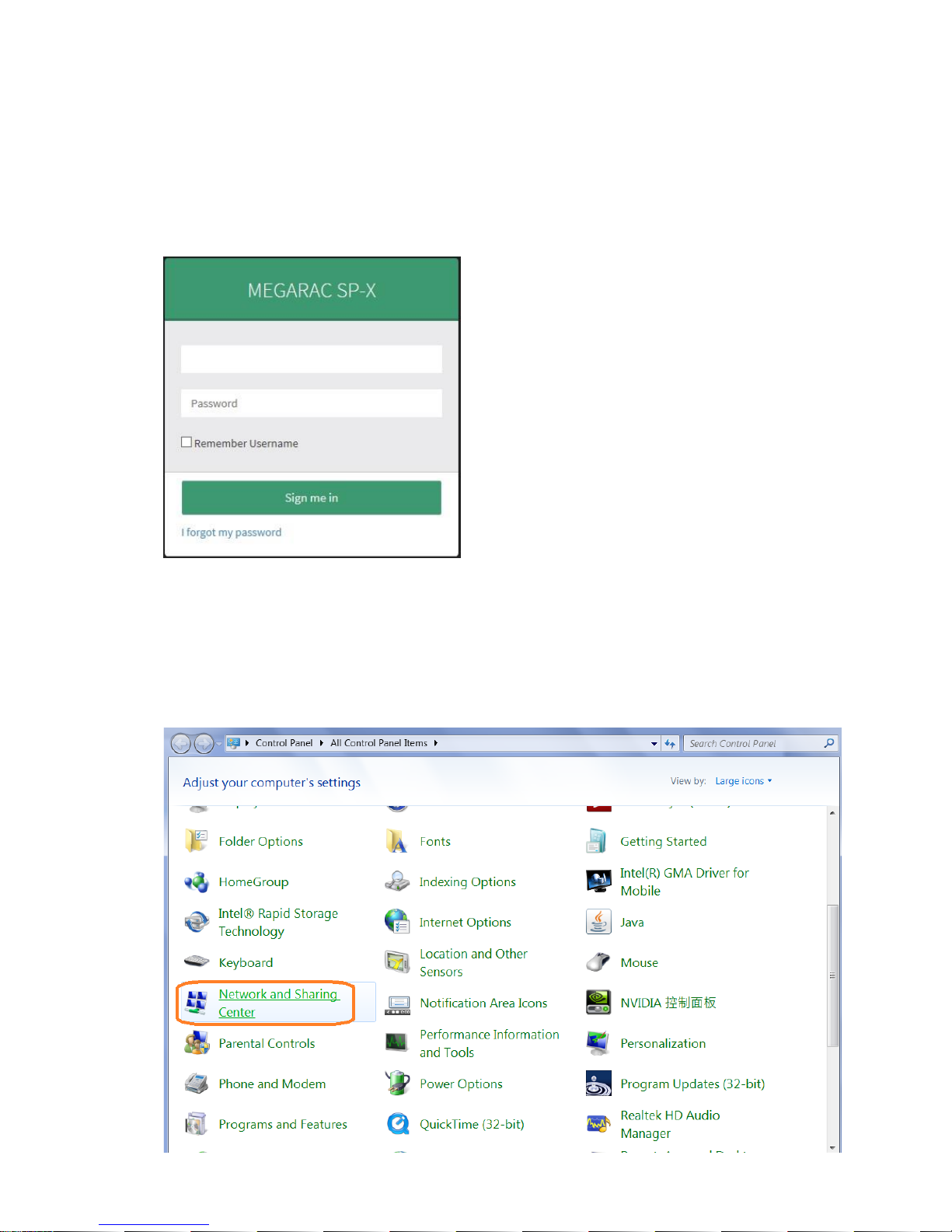
2-1-1 To remote manage the server, login into BMC web UI. For first time use, enter the default user name and
password. This can be found on label on the server. After entering the username and password, click on
the “Sign me in” button.
2-1-2 If the password is forgotten, a new one can be generated by clicking on “I forgot my password”.
2-1-3 If the server BMC LAN port (Also called Management LAN port) is not connected DHCP server, a static IP
address will need to be setup. Click on [Network and Sharing Center] item in Control Panel.
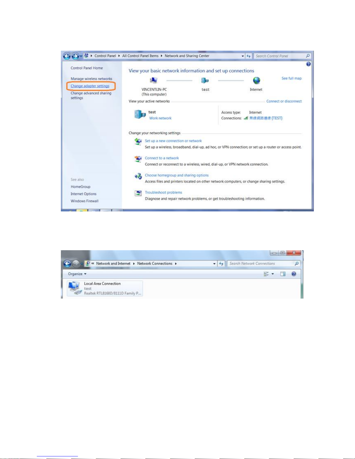
2-1-4 Click on [Change adapter settings]
2-1-5 Double click [local area network connection] item.
2-1-6 Click [Properties] item.
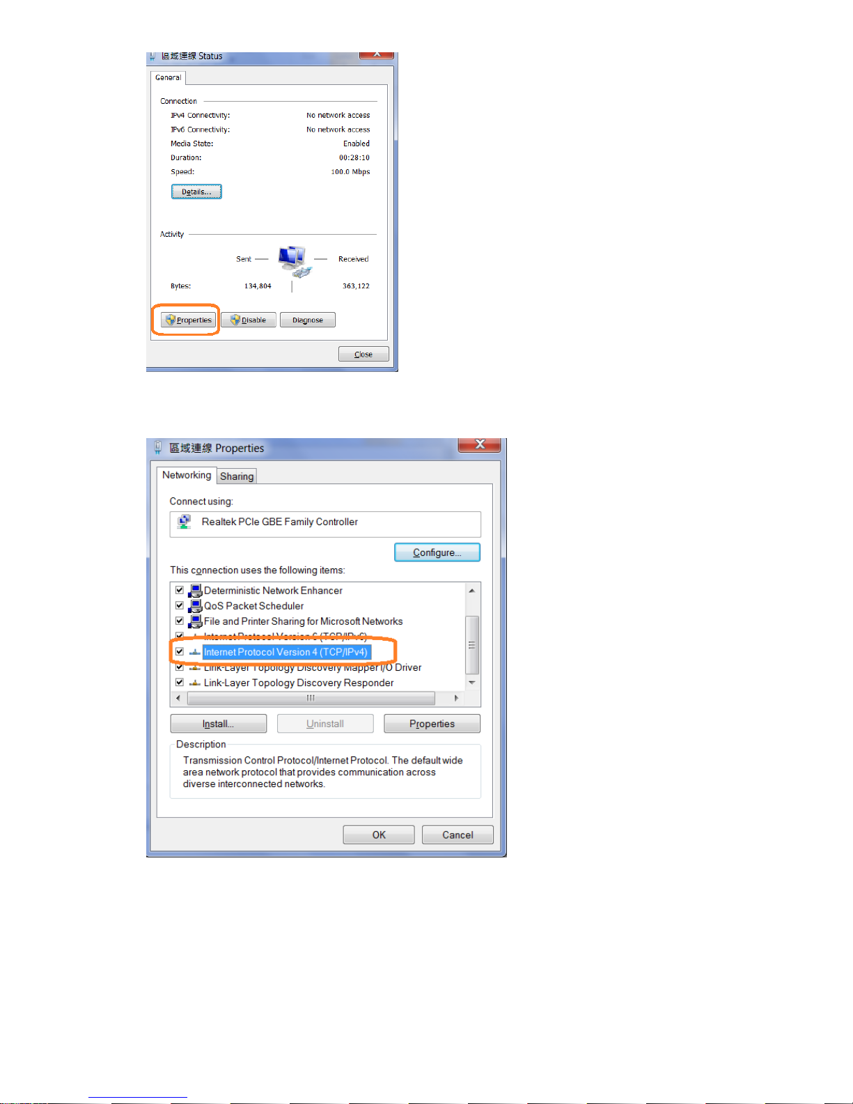
2-1-7 Click [Internet Protocol Version 4 (TCP/IPv4) item.
2-1-8 Select [Use the following IP address] and enter a static IP address and subnet mask. This address should
be from the same network and segment as the client PC network setting. (Static IP for example)
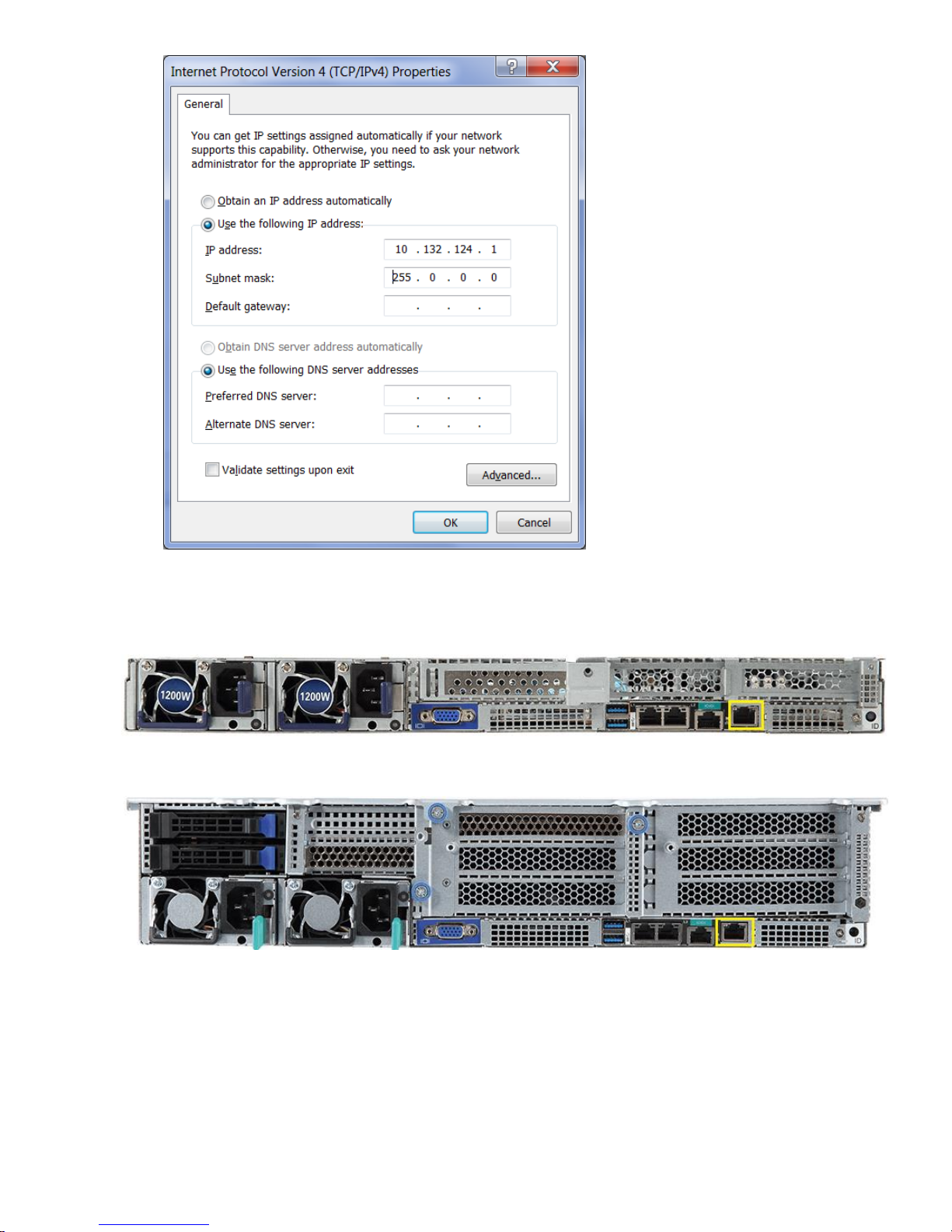
2-1-9 Connect an Ethernet cable between the host server BMC LAN port and the client PC LAN port.
CL2100 Gen10 Server:
CL2200 Gen10 Server:
2-1-10 Power on the system, and press [Del] key to enter BIOS Setup Utility. Go to the [Server Mgmt ] tab
and select [BMC network Configuration] item. Press the [Enter] key.
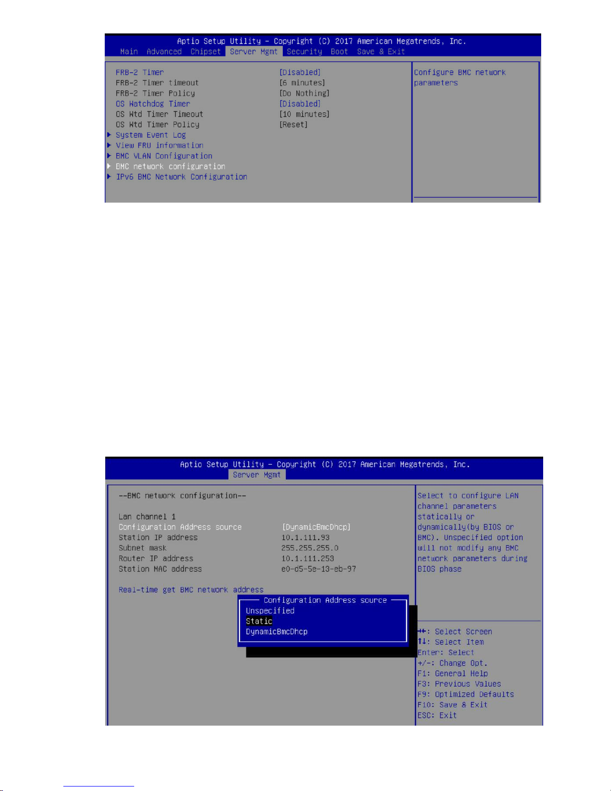
2-1-11 Press the [Enter] key to “configuration address source” and change to [Static] option.
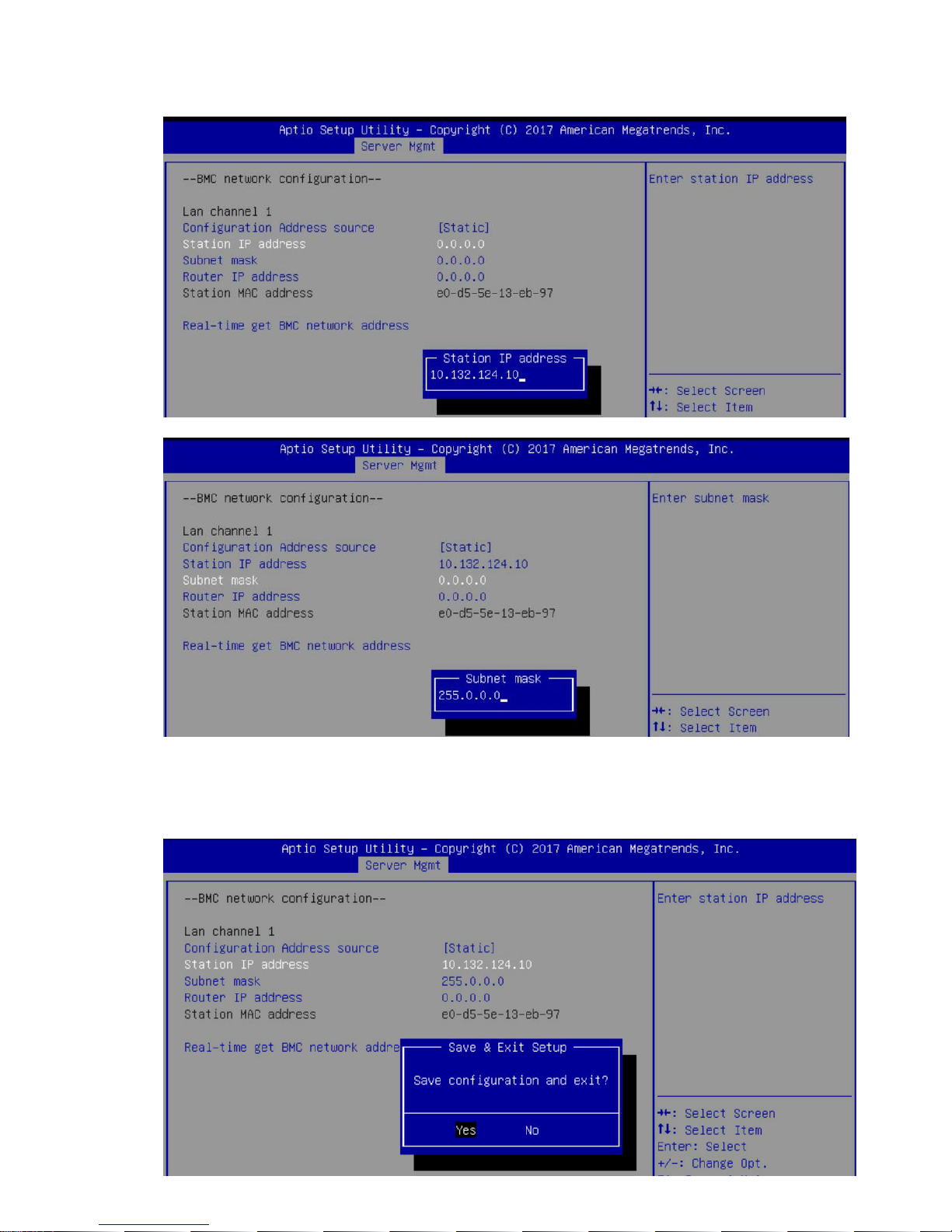
2-1-12 Next, select “Station IP Address” option and enter the IP Address. Next select subnet mask option,
add enter the subset mask address (Static IP example).
2-1-13 After entering the static IP and subnet mask addresses, press the [F10] key, select “Yes” and press the
[Enter] key to save the configuration and exit.
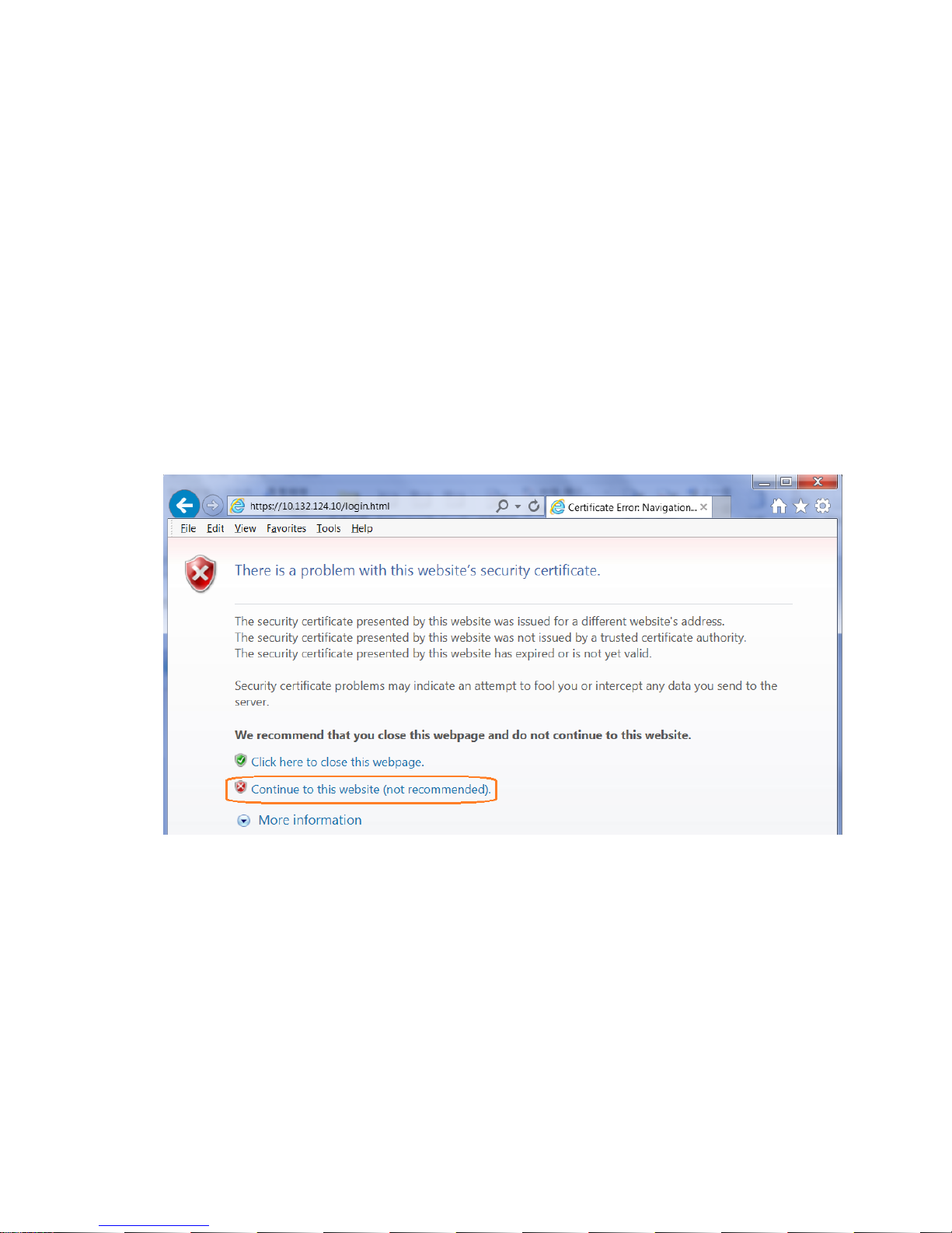
2-1-14 Next, enter the IP address in browser’s web address field. You will see a “There is a problem with this
website’s security certificate” webpage. Click on [Continue to this website (not recommended)].
Afterwards, you will see the IPMI logon webpage. This will allow you to link to the BMC web UI.
2-1-15 Login to the Management Console (BMC web UI). After you successfully login into the Management
Console, the remote management console GUI will appear.
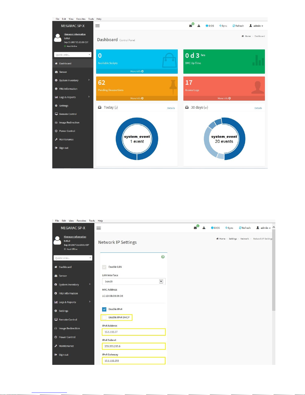
2-1-16 Network Interface Configuration: To change from DHCP to static IP, please click on [Settings]
[Network Settings] [Network IP Settings] Disable IPv4 DHCP Enter IPv4 Address, IPv4 Subnet and
IPv4 Gateway for static IP address.
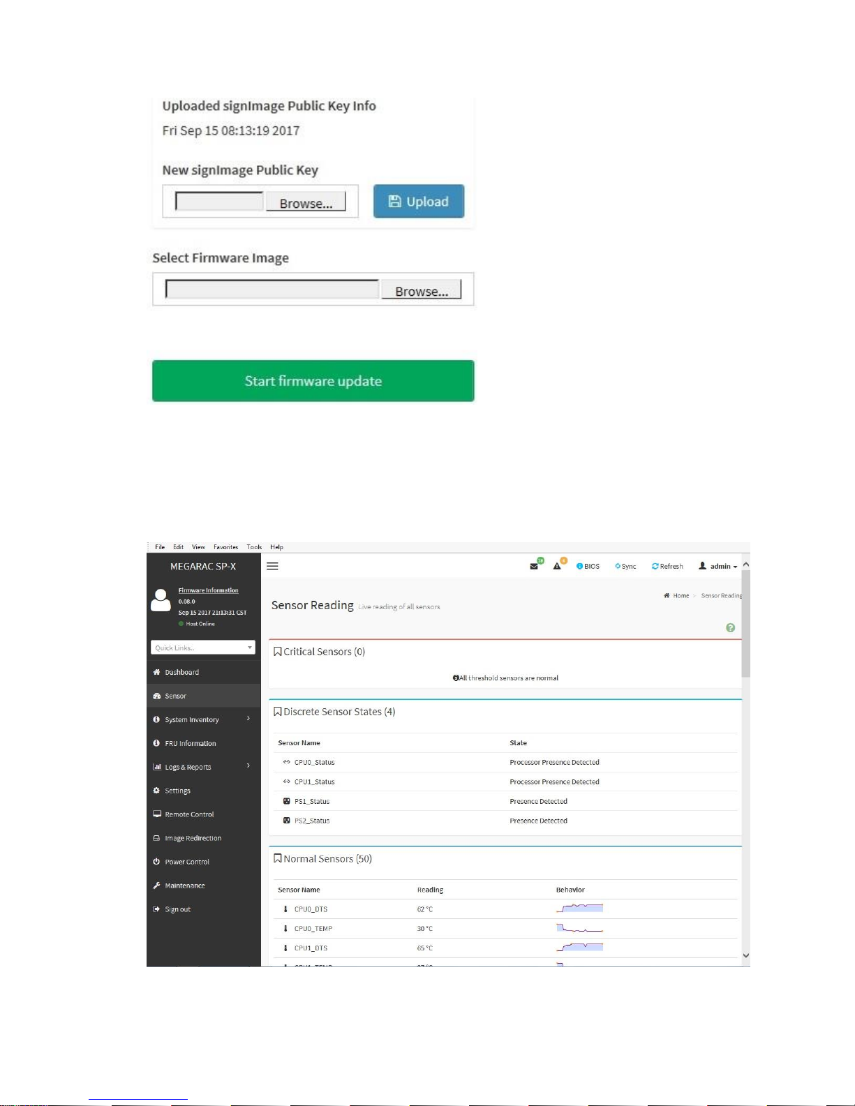
2-1-17 Updates: To update the BMC firmware, click on [Maintenance] [Firmware Update] [Select
Firmware Image] click [Browse] button.
2-1-18 Sensor: To check the server health status, click on [Sensor]. The Sensor Reading webpage will
appear.
2-1-19 To find out the CPU temperature, click on [CPU0_TEMP] or [CPU1_TEMP] to get the current CPU
temperature and Upper Critical CPU temperature
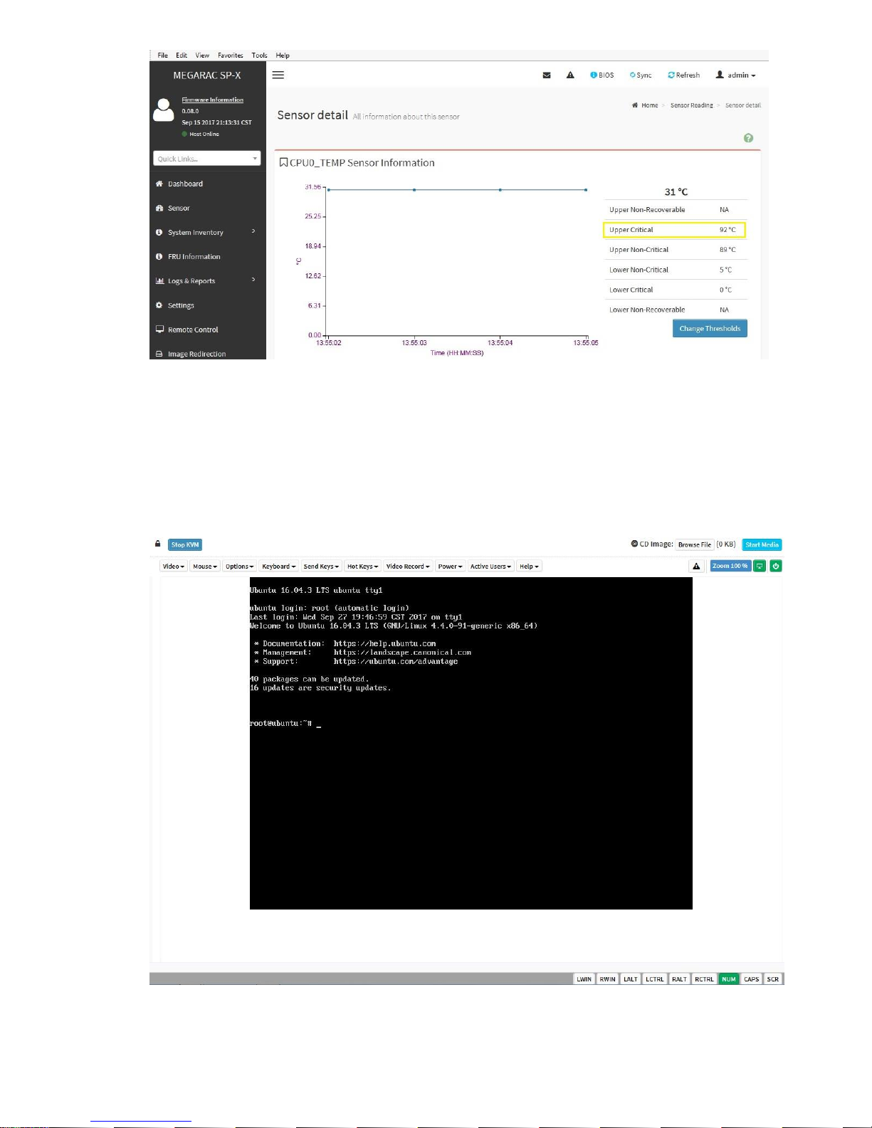
2-1-20 Remote Access: Click on [Remote Control] and click on [Launch KVM].
2-2 Checking for errors
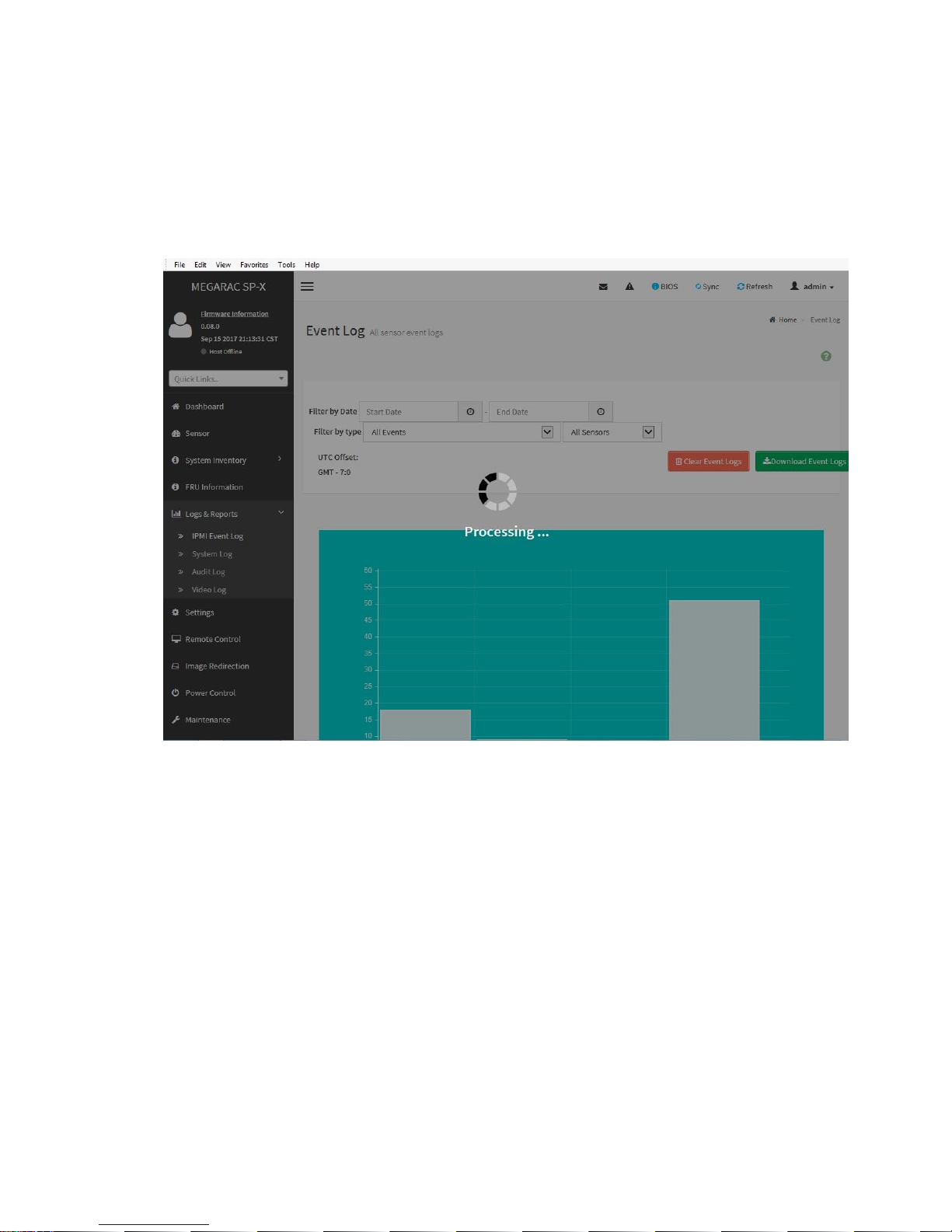
2-2-1 System event log: The system event log records an event when the sensor detects an abnormal state. When
the log matches a predefined alert, the server system will send out a notification. To determine what the
abnormal state is, click on [Logs & Reports] and select [IPMI Event Log]. Examples of abnormal states
include: CPU upper non-critical, voltage Lower critical, system fan lower critical, etc.
 Loading...