

Page 1

HPE Cloudline CL2100 / CL2200 Gen10
Abstract
This document is for the person who installs, administers, services, and troubleshoots servers. This guide describes identification and
maintenance procedures, and specifications and requirements for hardware components and software. Hewlett Packard Enterprise
assumes you are qualified in the servicing of computer equipment, trained in recognizing hazards in products, and are familiar with weight
and stability precautions.
Server
Troubleshooting Guide
Part Number: P04906-001a
December 2017
Edition: 1
Page 2

© Copyright 2017 Hewlett Packard Enterprise Development LP
The information contained herein is subject to change without notice. The only warranties for Hewlett Packard Enterprise products and services
are set forth in the express warranty statements accompanying such products and services. Nothing herein should be construed as constituting
an additional warranty. Hewlett Packard Enterprise shall not be liable for technical or editorial errors or omissions contained herein.
Links to third-party websites take you outside the Hewlett Packard Enterprise website. Hewlett Packard Enterprise has no control over and is not
responsible for information outside the Hewlett Packard Enterprise website.
Microsoft®, Windows®, and Windows Server® are either registered trademarks or trademarks of Microsoft Corporation in the United States
and/or other countries. Intel® and Xeon® are trademarks of Intel Corporation in the U.S. and other countries.
Page 3
Chapter 1 BIOS POST / Beep Code
1-1 BIOS POST Code
PEI_CORE_STARTED
0x10
PEI_CAR_CPU_INIT
0x11
// reserved for CPU 0x12 - 0x14
PEI_CAR_NB_INIT
0x15
// reserved for NB 0x16 - 0x18
PEI_CAR_SB_INIT
0x19
// reserved for SB 0x1A - 0x1C
PEI_MEMORY_SPD_READ
0x1D
PEI_MEMORY_PRESENCE_DETECT
0x1E
PEI_MEMORY_TIMING
0x1F
PEI_MEMORY_CONFIGURING
0x20
PEI_MEMORY_INIT
0x21
// reserved for OEM use: 0x22 - 0x2F
// reserved for AML use: 0x30
PEI_MEMORY_INSTALLED
0x31
PEI_CPU_INIT
0x32
PEI_CPU_CACHE_INIT
0x33
PEI_CPU_BSP_SELECT
0x34
PEI_CPU_AP_INIT
0x35
PEI_CPU_SMM_INIT
0x36
PEI_MEM_NB_INIT
0x37
// reserved for NB 0x38 - 0x3A
PEI_MEM_SB_INIT
0x3B
// reserved for SB 0x3C - 0x3E
// reserved for OEM use: 0x3F - 0x4E
PEI_DXE_IPL_STARTED
0x4F
//Recovery
PEI_RECOVERY_AUTO
0xF0
PEI_RECOVERY_USER
0xF1
PEI_RECOVERY_STARTED
0xF2
PEI_RECOVERY_CAPSULE_FOUND
0xF3
PEI_RECOVERY_CAPSULE_LOADED
0xF4
//S3
PEI_S3_STARTED
0xE0
Page 4
PEI_S3_BOOT_SCRIPT
0xE1
PEI_S3_VIDEO_REPOST
0xE2
PEI_S3_OS_WAKE
0xE3
//DXE_STATUS_CODE
DXE_CORE_STARTED
0x60
DXE_NVRAM_INIT
0x61
DXE_SBRUN_INIT
0x62
DXE_CPU_INIT
0x63
//reserved for CPU 0x64 - 0x67
DXE_NB_HB_INIT
0x68
DXE_NB_INIT
0x69
DXE_NB_SMM_INIT
0x6A
//reserved for NB 0x6B - 0x6F
DXE_SB_INIT
0x70
DXE_SB_SMM_INIT
0x71
DXE_SB_DEVICES_INIT
0x72
//reserved for SB 0x73 - 0x77
DXE_ACPI_INIT
0x78
DXE_CSM_INIT
0x79
//reserved for AMI use: 0x7A - 0x7F
//reserved for OEM use: 0x80 - 0x8F
DXE_BDS_STARTED
0x90
DXE_BDS_CONNECT_DRIVERS
0x91
DXE_PCI_BUS_BEGIN
0x92
DXE_PCI_BUS_HPC_INIT
0x93
DXE_PCI_BUS_ENUM
0x94
DXE_PCI_BUS_REQUEST_RESOURCES
0x95
DXE_PCI_BUS_ASSIGN_RESOURCES
0x96
DXE_CON_OUT_CONNECT
0x97
DXE_CON_IN_CONNECT
0x98
DXE_SIO_INIT
0x99
DXE_USB_BEGIN
0x9A
DXE_USB_RESET
0x9B
DXE_USB_DETECT
0x9C
DXE_USB_ENABLE
0x9D
//reserved for AMI use: 0x9E - 0x9F
//reserved for AML use: 0xA0
DXE_IDE_BEGIN
0xA1
Page 5
DXE_IDE_RESET
0xA2
DXE_IDE_DETECT
0xA3
DXE_IDE_ENABLE
0xA4
DXE_SCSI_BEGIN
0xA5
DXE_SCSI_RESET
0xA6
DXE_SCSI_DETECT
0xA7
DXE_SCSI_ENABLE
0xA8
DXE_SETUP_VERIFYING_PASSWORD
0xA9
//reserved for AML use: 0xAA
DXE_SETUP_START
0xAB
DXE_SETUP_INPUT_WAIT
0xAC
DXE_READY_TO_BOOT
0xAD
DXE_LEGACY_BOOT
0xAE
DXE_EXIT_BOOT_SERVICES
0xAF
RT_SET_VIRTUAL_ADDRESS_MAP_BEGIN
0xB0
RT_SET_VIRTUAL_ADDRESS_MAP_END
0xB1
DXE_LEGACY_OPROM_INIT
0xB2
DXE_RESET_SYSTEM
0xB3
DXE_USB_HOTPLUG
0xB4
DXE_PCI_BUS_HOTPLUG
0xB5
DXE_NVRAM_CLEANUP
0xB6
DXE_CONFIGURATION_RESET
0xB7
//reserved for AMI use: 0xB8 - 0xBF
//reserved for OEM use: 0xC0 - 0xCF
//PEI_STATUS_CODE
//Errors
//Regular boot
PEI_MEMORY_INVALID_TYPE
0x50
PEI_MEMORY_INVALID_SPEED
0x50
PEI_MEMORY_SPD_FAIL
0x51
PEI_MEMORY_INVALID_SIZE
0x52
PEI_MEMORY_MISMATCH
0x52
PEI_MEMORY_NOT_DETECTED
0x53
PEI_MEMORY_NONE_USEFUL
0x53
PEI_MEMORY_ERROR
0x54
PEI_MEMORY_NOT_INSTALLED
0x55
PEI_CPU_INVALID_TYPE
0x56
PEI_CPU_INVALID_SPEED
0x56
Page 6

PEI_CPU_MISMATCH
0x57
PEI_CPU_SELF_TEST_FAILED
0x58
PEI_CPU_CACHE_ERROR
0x58
PEI_CPU_MICROCODE_UPDATE_FAILED
0x59
PEI_CPU_NO_MICROCODE
0x59
PEI_CPU_INTERNAL_ERROR
0x5A
PEI_CPU_ERROR
0x5A
PEI_RESET_NOT_AVAILABLE
x5B
//reserved for AMI use: 0x5C - 0x5F
//Recovery
PEI_RECOVERY_PPI_NOT_FOUND
0xF8
PEI_RECOVERY_NO_CAPSULE
0xF9
PEI_RECOVERY_INVALID_CAPSULE
0xFA
//reserved for AMI use: 0xFB - 0xFF
//S3 Resume
PEI_MEMORY_S3_RESUME_FAILED
0xE8
PEI_S3_RESUME_PPI_NOT_FOUND
0xE9
PEI_S3_BOOT_SCRIPT_ERROR
0xEA
PEI_S3_OS_WAKE_ERROR
0xEB
//reserved for AMI use: 0xEC - 0xEF
// DXE_STATUS_CODE
DXE_CPU_ERROR
0xD0
DXE_NB_ERROR
0xD1
DXE_SB_ERROR
0xD2
DXE_ARCH_PROTOCOL_NOT_AVAILABLE
0xD3
DXE_PCI_BUS_OUT_OF_RESOURCES
0xD4
DXE_LEGACY_OPROM_NO_SPACE
0xD5
DXE_NO_CON_OUT
0xD6
DXE_NO_CON_IN
0xD7
DXE_INVALID_PASSWORD
0xD8
DXE_BOOT_OPTION_LOAD_ERROR
0xD9
DXE_BOOT_OPTION_FAILED
0xDA
DXE_FLASH_UPDATE_FAILED
0xDB
DXE_RESET_NOT_AVAILABLE
0xDC
//reserved for AMI use: 0xDE - 0xDF
Page 7
1-2 BIOS POST Beep Code
1-2-1 PEI Beep Codes
# of Beeps
Description
1
Memory not Installed.
1
Memory was installed twice (InstallPeiMemory routine in PEI Core called twice)
2
Recovery started
3
DXEIPL was not found
3
DXE Core Firmware Volume was not found
4
Recovery failed
4
S3 Resume failed
7
Reset PPI is not available
1-2-2 DEX Beep Codes
# of Beeps
Description
1
Invalid password
4
Some of the Architectural Protocols are not available
5
No Console Output Devices are found
5
No Console Input Devices are found
6
Flash update is failed
7
Reset protocol is not available
8
Platform PCI resource requirements cannot be met
Page 8
Chapter 2 Remote Troubleshooting
2-1 WebUI
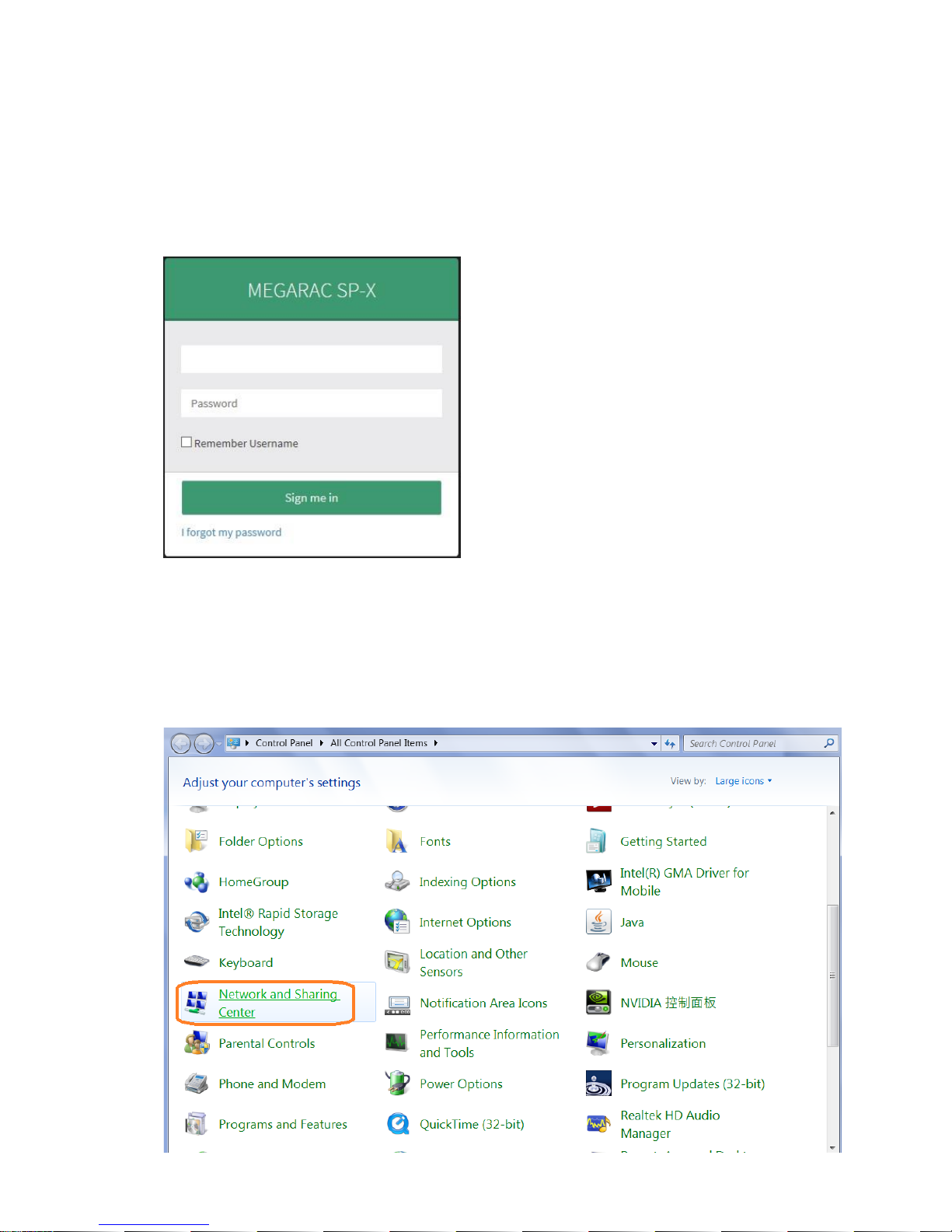
2-1-1 To remote manage the server, login into BMC web UI. For first time use, enter the default user name and
password. This can be found on label on the server. After entering the username and password, click on
the “Sign me in” button.
2-1-2 If the password is forgotten, a new one can be generated by clicking on “I forgot my password”.
2-1-3 If the server BMC LAN port (Also called Management LAN port) is not connected DHCP server, a static IP
address will need to be setup. Click on [Network and Sharing Center] item in Control Panel.
Page 9
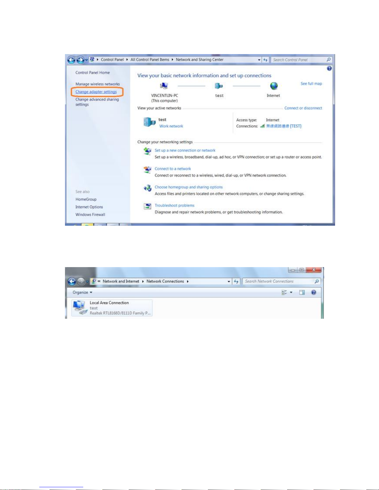
2-1-4 Click on [Change adapter settings]
2-1-5 Double click [local area network connection] item.
2-1-6 Click [Properties] item.
Page 10
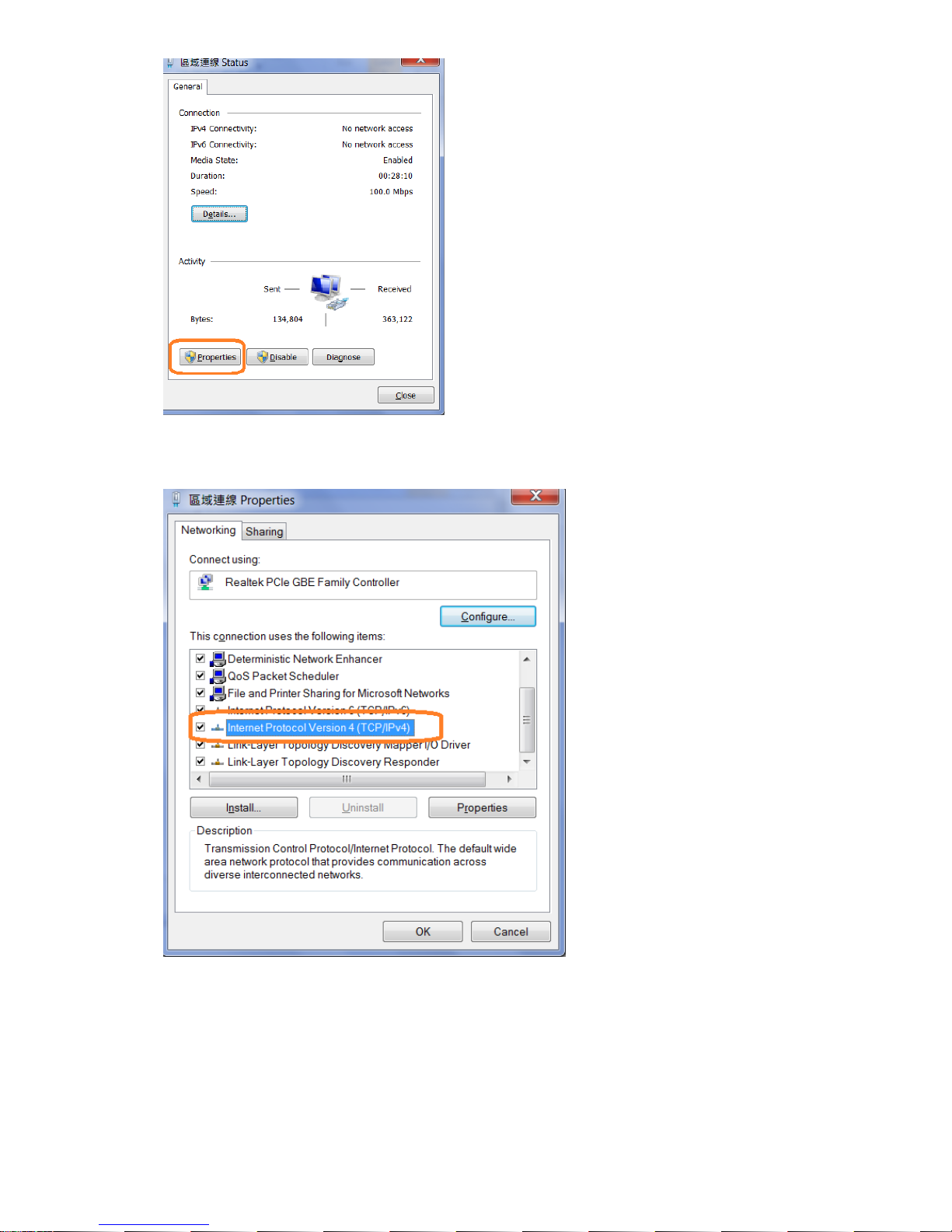
2-1-7 Click [Internet Protocol Version 4 (TCP/IPv4) item.
2-1-8 Select [Use the following IP address] and enter a static IP address and subnet mask. This address should
be from the same network and segment as the client PC network setting. (Static IP for example)
Page 11
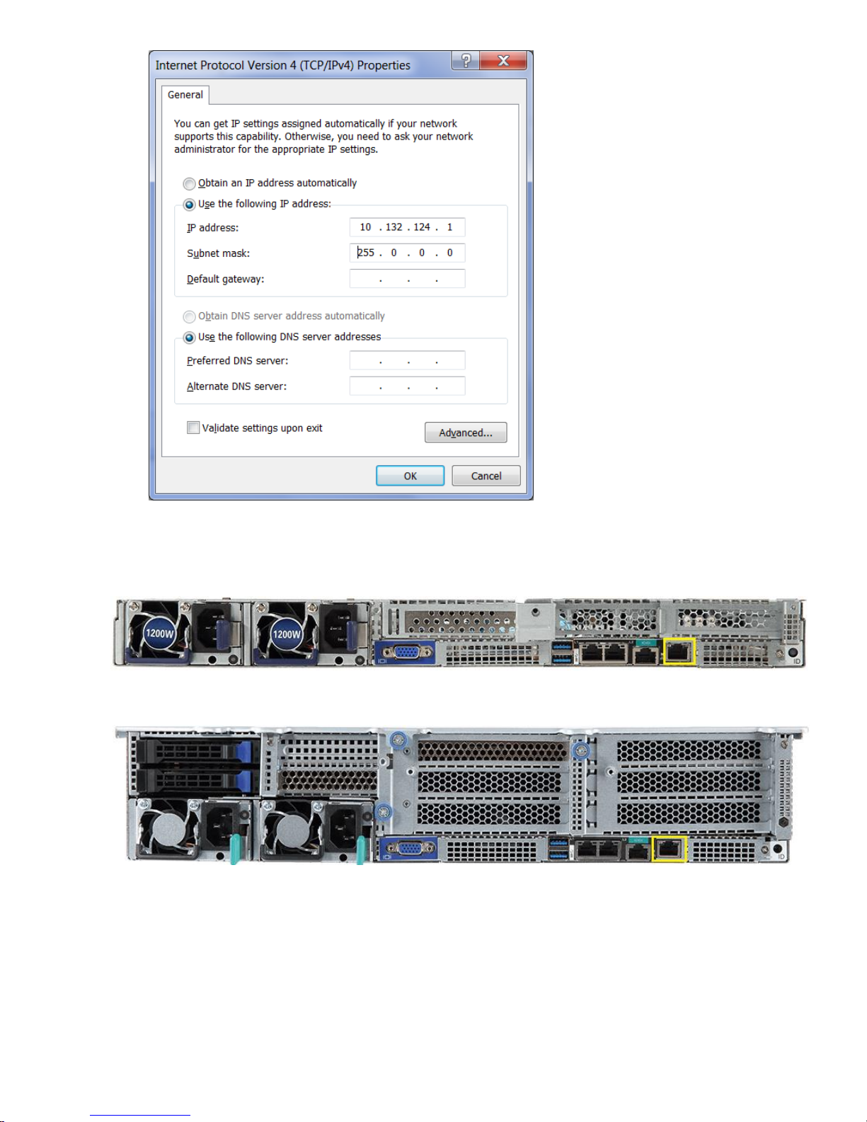
2-1-9 Connect an Ethernet cable between the host server BMC LAN port and the client PC LAN port.
CL2100 Gen10 Server:
CL2200 Gen10 Server:
2-1-10 Power on the system, and press [Del] key to enter BIOS Setup Utility. Go to the [Server Mgmt ] tab
and select [BMC network Configuration] item. Press the [Enter] key.
Page 12
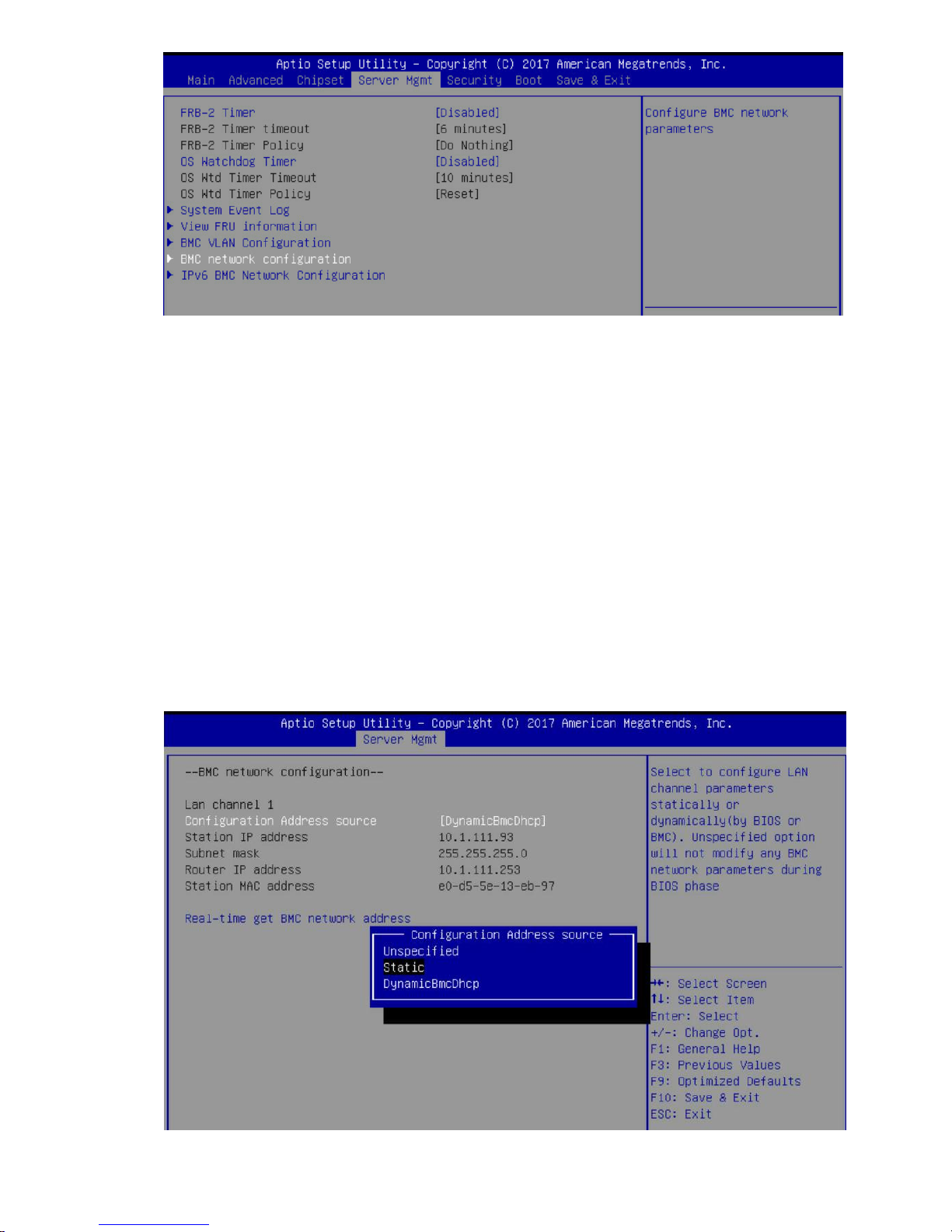
2-1-11 Press the [Enter] key to “configuration address source” and change to [Static] option.
Page 13
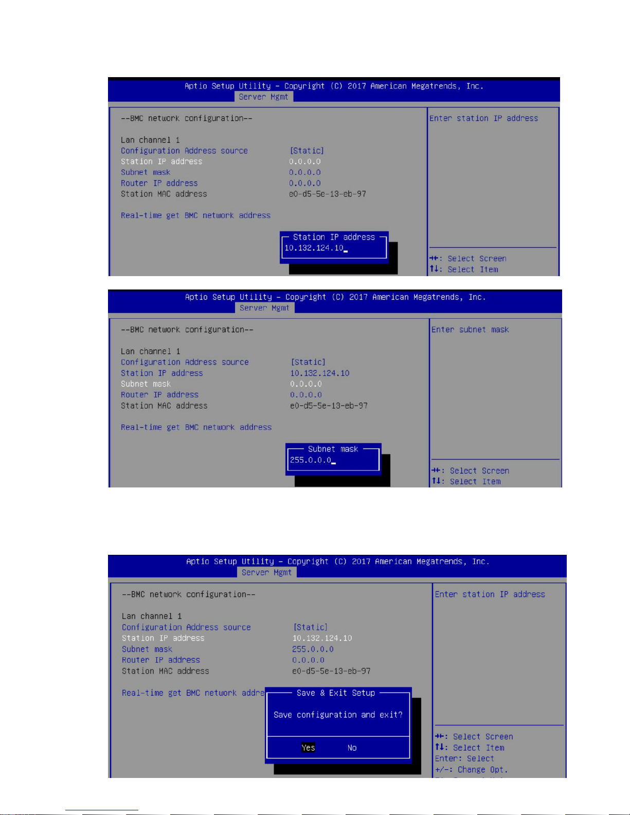
2-1-12 Next, select “Station IP Address” option and enter the IP Address. Next select subnet mask option,
add enter the subset mask address (Static IP example).
2-1-13 After entering the static IP and subnet mask addresses, press the [F10] key, select “Yes” and press the
[Enter] key to save the configuration and exit.
Page 14
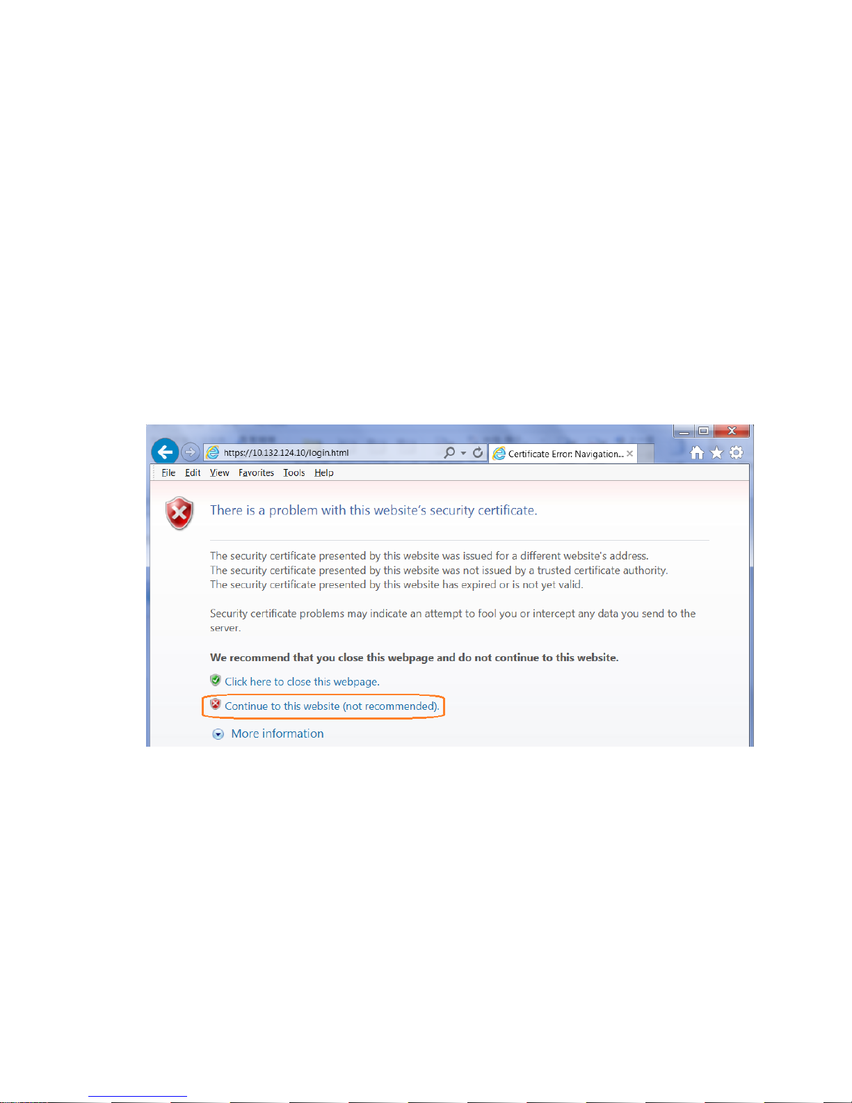
2-1-14 Next, enter the IP address in browser’s web address field. You will see a “There is a problem with this
website’s security certificate” webpage. Click on [Continue to this website (not recommended)].
Afterwards, you will see the IPMI logon webpage. This will allow you to link to the BMC web UI.
2-1-15 Login to the Management Console (BMC web UI). After you successfully login into the Management
Console, the remote management console GUI will appear.
Page 15
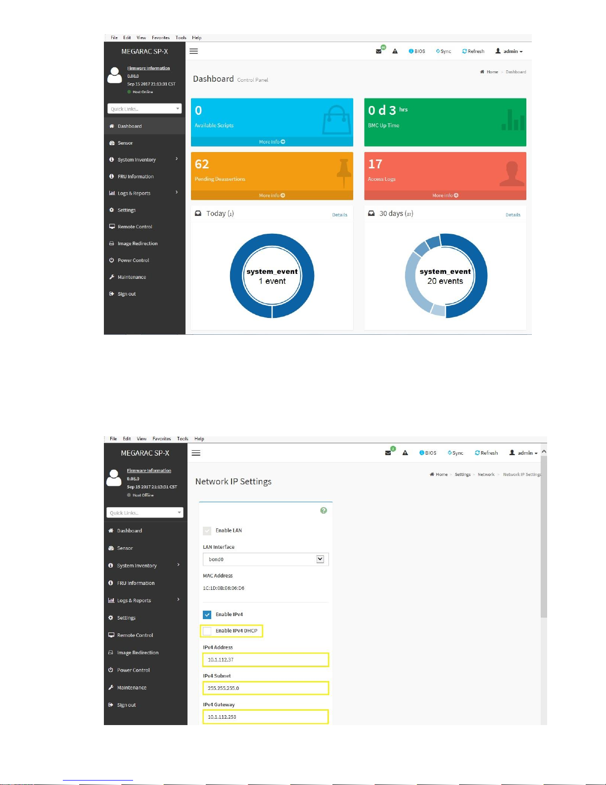
2-1-16 Network Interface Configuration: To change from DHCP to static IP, please click on [Settings]
[Network Settings] [Network IP Settings] Disable IPv4 DHCP Enter IPv4 Address, IPv4 Subnet and
IPv4 Gateway for static IP address.
Page 16
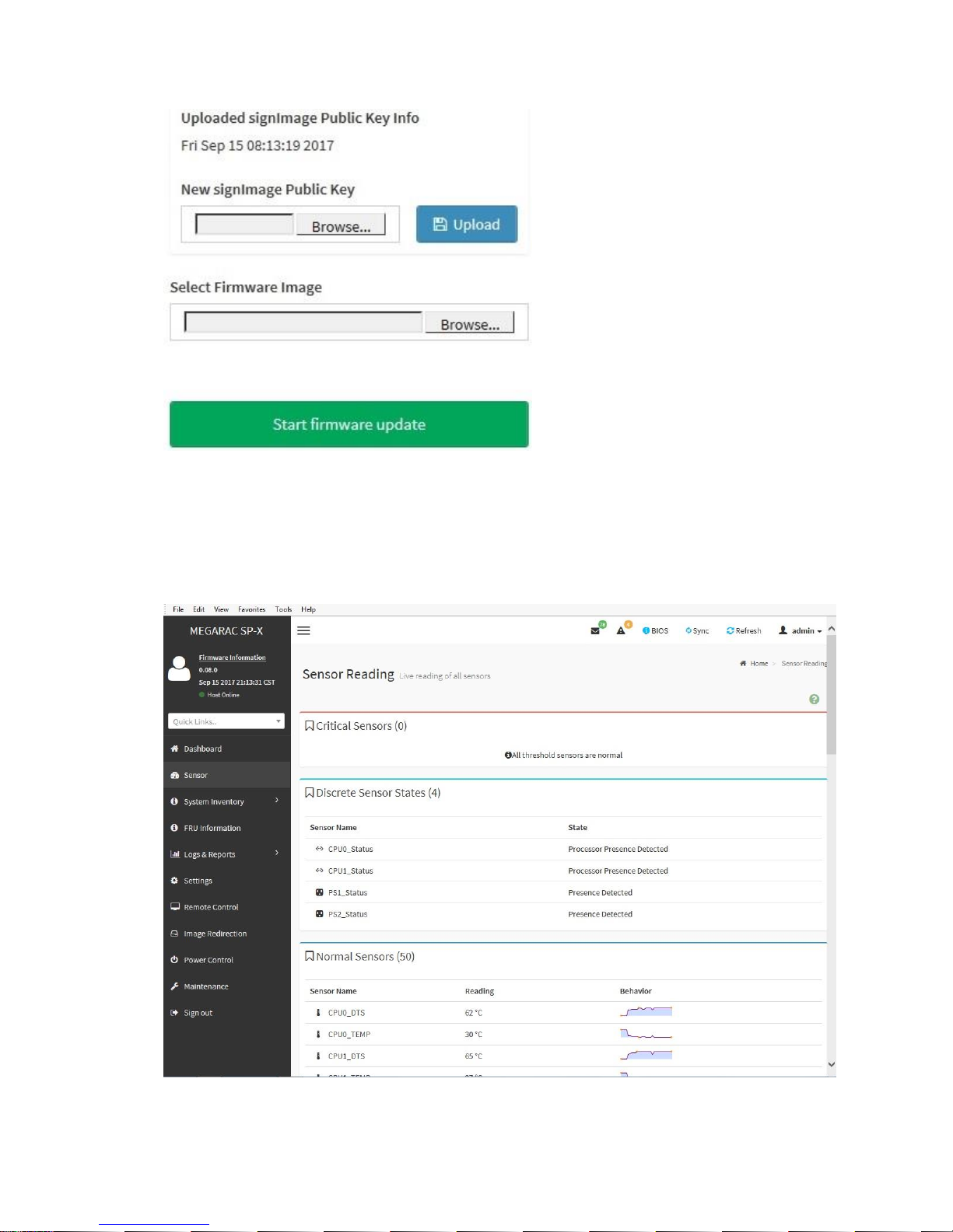
2-1-17 Updates: To update the BMC firmware, click on [Maintenance] [Firmware Update] [Select
Firmware Image] click [Browse] button.
2-1-18 Sensor: To check the server health status, click on [Sensor]. The Sensor Reading webpage will
appear.
2-1-19 To find out the CPU temperature, click on [CPU0_TEMP] or [CPU1_TEMP] to get the current CPU
temperature and Upper Critical CPU temperature
Page 17
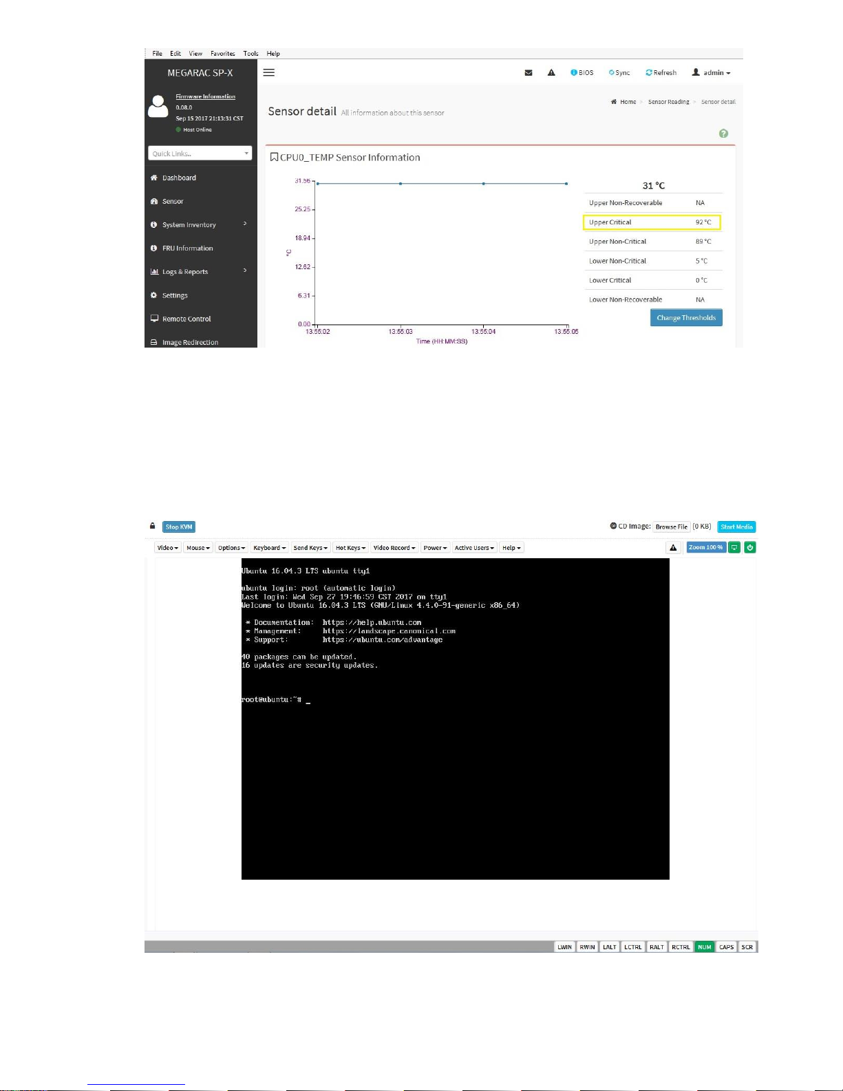
2-1-20 Remote Access: Click on [Remote Control] and click on [Launch KVM].
Page 18
2-2 Checking for errors
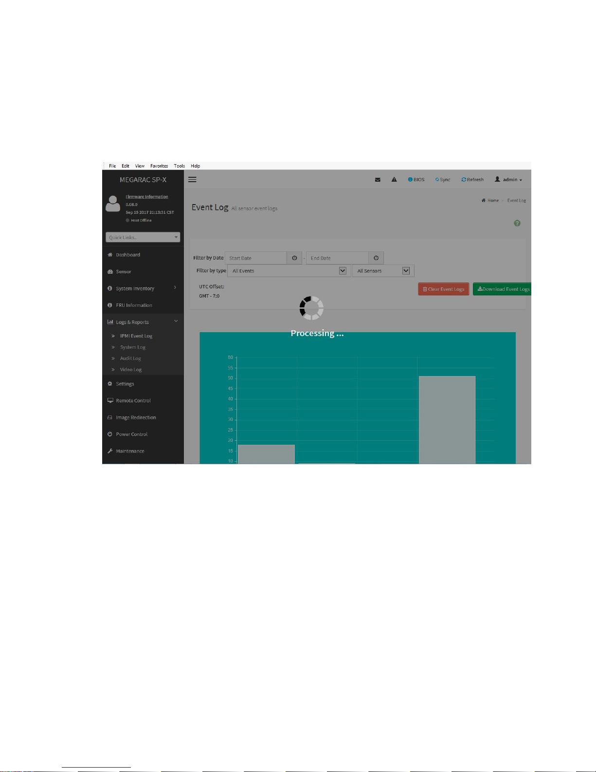
2-2-1 System event log: The system event log records an event when the sensor detects an abnormal state. When
the log matches a predefined alert, the server system will send out a notification. To determine what the
abnormal state is, click on [Logs & Reports] and select [IPMI Event Log]. Examples of abnormal states
include: CPU upper non-critical, voltage Lower critical, system fan lower critical, etc.
Page 19

2-2-2 Server Health Status: Use the Dashboard to determine the server health status. If the server is in “good”
health, the “Sensor Monitoring” status bar will report all “sensors are good now!”
2-2-3 To download the event log for analysis, click on [IPMI Event Log] in the menu and then click on the
[Download Event Logs] button.
Page 20

Chapter 3 Diagnostic Flowchart
3-1 Start diagnostic flowchart
Use the following flowchart to start the diagnostic process.
Start
Diagnosis
Do you want to perform
the Remote Diagnosis?
Does the
Server power on?
Does the
Server complete POST?
Are physical drives not
shown or are errors displayed
during POST?
Are logical drives not shown
or are errors displayed during
POST?
Does the server
boot to the OS
Does the
server have insight
Management Agent fault or
LED fault indication?
Go to
Remote
Diagnosis
Go to Power
On Issues
Go to POST
Issues
Go to
Physical
Drive Issues
Go to
Logical
Drive Issues
Go To OS
Boot Issues
Is the NIC working?
Go to
Server Fault
Indications
Go to NIC
Issues
Go to
General
Diagnosis
Yes
No
Yes
No
Yes
No
No
Yes
No
Yes
No
Yes
Yes
No
No
Yes
Page 21

3-2 Remote diagnostic flowchart
The Remote diagnosis flowchart provides a generic approach to troubleshooting a server from a remote location.
Use WebUI to
troubleshooting
Does the
condition still
exist?
End
Start Remote
Troubleshooting
Contact Support
Download system
event log file
Yes
No
Page 22

3-3 Power On issue flowchart
For the location of server LEDs and information on their status, see Chapter 1 System Appearance.
Symptoms
The server does not power on.
The system power button LED is off or Blinking Green.
Cause
Improperly seated or faulty power supply.
Loose or faulty power cord.
Power source issue.
Improperly seated component or interlock issue.
Page 23

Action
To troubleshoot the issue, use the following flowcharts:
Start power on issue
Are PSU
installed?
What is the status
of PSUs
What color is the Power
Button LED after press
power button
If the power source
operating properly?
Replace the power
source
Install PSU
Check for loost
power cables.
Install power cable
and PSU again
Check for loose
internal cables
Install internal cables
again
Replace the power
supply
Does the
condition still
exist?
Contact Support with
sufficient information
End
Press Power Button
to let system back to
S0
Is the Power Button LED
blink or solid gree?
Check for VGA cables
Check Monitor with
other system
No
Yes
Off
On
Green
Off
Yes
No
No
Yes
Blink
Solid
Page 24

3-4 POST issue flowchart
Symptoms
The server does not complete POST.
The server completes POST with errors.
Cause
Improperly populated memory.
Outdated firmware on adapter options.
Unsupported adapter.
Improperly seated or faulty internal component.
Faulty video device.
Page 25

Action
Troubleshoot the issue using the following flowcharts:
Start POST issues
Does the system
have power?
Go to Power
on issues
flowchart
What color is the
system power LED
Is Video displayed
Is Video cabled
Correctly
Has system
attempted to boot an
OS?
Are POST error
messages
displayed?
Did system show
the post code?
Does issue still
exist?
Correct the video
cabling. See the server
user guide.
Go to OS
boot issues
flowchart
Review the post code
on Chapter 2" BIOS
POST/Beep Code”
Check and solve error
message
End
Check IPMI event log
using webUI and
follow instructions.
Does the condition
still exist
End
Check for cable loose connections.
If ReseatIng devices indicated by
system status LEDs and the
condition still exists, replace the
device.
Does the condition
still exist?
Update all device
firmware to the latest
version.
Does the condition
still exist?
Before contacting support, gather
important symptom information for
use in troubleshooting the issue.
Contact Support
Yes
No
No
Yes
Yes
No
Yes Yes
No
Yes
No
No
No
No
No
No
Yes
Off
Solid
green
Yes
Yes
Yes
Page 26

3-5 Physical drive issue flowchart
Symptoms
A drive is not available.
Drive errors are displayed during POST in the logs.
Cause
The drive is faulty.
The firmware is outdated.
The drive does not match other drives in the same configuration.
Page 27

Action
Troubleshoot the issue using the following flowcharts:
Start physical
drive issues
Gather Important symptom
information for use in
troubleshooting the issues
Is the drive a
QVL drive?
Install a QVL drive
Does the condition
still exist
Is drive failure
intermittent?
Update drive firmware
Does the condition
still exist
Is the drive
failure permanent?
Replace the drive.
Does the condition
still exist
Does the drive match other
drive in the configuration
Replace the drive with a drive
that is supported by the
configuration.
Does the condition
still exist
Are the drive-related POST
error message being
displayed?
Resolve the issue displayed in
the error message.
Does the condition
still exist
Does the condition
still exist
End
No
No
No
No
No
No
No
No
No
No
Yes
Yes
Yes
Yes
Yes
Yes
Yes
Yes
Yes
Yes
Yes
No
Contact support
Page 28

3-6 Logical drive issue flowchart
Symptoms
Logical drive errors are displayed during POST or in one of the logs.
The logical drives associated with an array controller are not visible during POST.
Cause
The controller is not in RAID mode.
The drives or cables are not seated properly.
The associated physical drives are not available.
Logical drives are configured.
Page 29

Action
Troubleshoot the issue using the following flowcharts:
Start Logical
drive issues
Is the controller
supported by the server?
Are logical drives
identified
Is hardware
RAID required?
Are associated
physical drives
visible?
Configure logical drives
Does the condition
still exist ?
Replace controller
with one supported in
the server.
If the controller is in
HBA mode, enable
RAID mode.
Configure drives
presented
individually via the
HBA
Reseat drives and
controller cables.
Are associated
physical drives now
Go to Physical drive
issues. Configure
logical drives when
physical drives are
available
Does the condition
still exist?
Are too many logical
drives identified?
Does the
configuration require
cache?
End
Resolve too many
logical drives by
updating the
controller firmware
or moving extra
drives to another
controller
Does the condition
still exist?
Reseat, install, or
replace the cache
module.
Does the condition
still exist?
No
Yes
No
Yes
No
Yes
Yes
No
Yes
No
No
Yes
Yes
Yes
Yes
No
No
No
No
No
Yes
Contact Support
Page 30

3-7 OS boot issue flowchart
Symptoms
The server does not boot a previously installed OS.
Cause
Corrupted OS.
Drive subsystem issue.
Incorrect setting in BIOS.
Action
Troubleshoot the issue using the following flowcharts:
Start OS Boot
issues
Has system
attempted to boot
an OS?
Does the
configured boot mode
match the OS installed on
the boot media?
Is
An OS
Installed on the
Intended boot
target?
Check for loose
connections
Does
condition still
exist?
If the controller
will host the
Boot device,
Ensure the
Device is
Configured
And set as
a boot device.
Does
Condition still
exist?
Configure boot
mode properly.
Ensure a valid OS is
installed on intended
boot target.
End
Does
condition still
exist?
Disable optimized
boot.
Is UEFI
Optimized boot
is disabled?
Before contacting
Support gather important
symptom information
For use in
Troubleshooting
the issue.
Contact Support
No
Yes
Yes
No
No
Yes
Yes
Yes
Yes
No
No
No
No
Yes
Yes
Page 31

3-8 Fault indication flowchart
Symptom
The server boots, but the System Status LED is amber or Blinking Green.
The server boots, but a fault event is reported by BMC.
Cause
Improperly seated or faulty internal or external component.
Unsupported component installed.
Redundancy failure.
System over temperature, over voltage condition, or over lower speed condition of FAN.
Processor or memory error.
BMC event log full.
Action
Troubleshoot the issue using the following flowcharts:
Page 32

Start Server fault
indications
Select an appropriate
Fault indicator.
IPMI event log
LEDs
Check and solve the problem
by IPMI event log.
Does condition still
exist?
End
No
Blinking Green Blinking Amber Solid Amber Off
CPU disable and
DIMM disable
Non-critical condition,
R-PSU fail (AC LOST),
Event log full, drive fault
Critical condition,
PSU fail, CPU error,
critical memory error
System
STOP(normal) ,
POST error, NMI
Is it System
STOP(normal)?
Contact Support
Yes
No
Yes
Page 33

3-9 NIC issue flowchart
Symptoms
The NIC is not working
One or more ports on the NIC are not working.
Cause
The firmware or drivers are outdated, mismatched, or faulty.
The NIC or cable is not seated properly.
The NIC, the cable, or other hardware is faulty.
The hardware components are not supported in the same configuration.
The NIC is not supported on the server.
Page 34

Action
NIC issues flowchart (1 of 2)
Start
NIC issues
Gather important symptom
information for use in
troubleshooting the issue
Did the NIC work
previously?
Were any
changes made
recenyly?
What changes
where made?
Reseat the NIC and
verify cabling is
connected properly.
Does condition
still exist?
Verify that the NIC is supported on the
server.
If new hardware was
added to the server
recently. Remove the
hardware
Verify that the firmware
and drivers are correct for
the hardware. Make
updates as required.
Update
firmware/drivers to
the most recent
supported version
Reinstall the previous
firmware or driver version
End
Does condition
still exist?
Does condition
still exist?
Does condition
still exist?
Does condition
still exist?
Does condition
still exist?
Go To NIC
issues p2
Troubleshoot and correct all
issues between the NIC and
switch or VC configuration:
-IP address setting
-Port speeds
-Port negotiation settings
-Switch port disabled
Does condition
still exist?
End
No
Yes
Yes
Yes
No
No
Server config
No
No
No
No
No
Yes
Yes
Yes
Yes
Yes
Network or
NIC config
No
Firmware or
driver updates
Yes
Page 35

NIC issues flowchart (2 of 2)
From NIC
Issues
p1
Contact
support
Does the
NIC load in
the OS
Enabled the driver
Does
condition still
exist?
Install/reinstall the
driver
Does
condition still
exist?
Eliminate a
firmware/driver mismatch
Does
condition still
exist?
Install
Firmware/driver update
Does
condition still
exist?
Yes
End
No
No
No
No
Yes
Yes
Yes
Yes
Does the
NIC appear at
POST and are there NIC
POST error Message
Or IPMI event log
Messages?
Reseat the NIC and verify
Cabling is connected properly.
Does
condition still
exist?
Verify that all SFP, Cables, connectors,
are operating properly. Replace
components that are damaged.
Does
condition still
exist?
Verify that no hardware
Compatibility issues exist. Make
necessary changes to
correct issues.
Does
condition still
exist?
No
Yes
Yes
No
Yes
Yes
Replace the NIC.
Does
condition still
exist?
End
Update to a supported NIC
firmware/driver set.
Does
condition still
exist?
Eliminate NIC and VC or switch
port configuration mismatches.
Does
condition still
exist?
Enabled the NIC in the
BIOS.
Does
condition still
exist?
Verify that the server does not
require a BIOS update to see the
NIC
No
No
No
No
No
No
Yes
Yes
Yes
Yes
No
Page 36

3-10 General diagnosis flowchart
The General diagnosis flowchart provides a generic approach to troubleshooting. If you are unsure of the issue, or if the
other flowcharts do not fix the issue, use the following flowchart.
Start
General Diagnosis
Gather important symptom
information for use in
troubleshooting the issue
Is the system
responding?
Go to POST
issues
flowchart
Reseat any devices that may
have come loose during
shipping and reboot the server.
Is the a newly
installed server?
Has server worked
previously?
Does the
condition still
exist?
Reseat any
components that may
have come loose
dunning shipping and
reboot the server
Restore default
system settings
Does condition
still exist?
Review the IPMI
event log and server
LEDs for errors.
Does condition
still exist?
Is server
receiving power?
Were
options added or was the
configuration changed
recently?
Download the latest
software and firmware
Does the
condition still
exist?
Isolate what wAs changed. Verify it
was installed correctly. Restore server
to the last known working state or
original shipped configuration.
Does the
condition still
exist?
Does the
condition still
exist?
Add one part at a time back to
configuration to isolate faulty component.
Break server down to
minimal configuration
Does the
condition still
exist?
Before contacting support, gather
important symptom information for use in
troubleshooting the issue.
Contact support
End
Go to power
on issue or
POST issues
flowchart
Are POST error
messages displayed?
Go to POST
issues
flowchart
Go to
Server fault
indications
flowchart
No
Yes
No
No
No
No
No
No
No
No
No
No
No
No
Yes
Yes
Yes
Yes
Yes
Yes
Yes
Yes
Yes
Yes
Yes
Yes
Yes
Page 37

Chapter 4 Hardware Issue
4-1 Power issue
4-1-1 Server does not power on
Symptom
The system does not power on.
Action
Check with Power On issue flowchart.
4-1-2 Power source issue
Cause
The server is not powered on.
Components or cables might not be properly connected or seated.
The grounded power outlet is not working.
The power cord is not functional.
The power strip is not functional.
The circuit breaker is in the off position.
The line voltage is insufficient for the load.
Sufficient power is not allocated to support the server.
Action
Press the Power button to be sure it is on. If the server has a Power button that returns to its original
position after being pressed, be sure you press the switch firmly.
Be sure no loose connections exist.
Plug another device into the grounded power outlet to be sure the outlet works. Also, be sure the power
source meets applicable standards.
Replace the power cord with a known functional power cord to be sure it is not faulty.
Replace the power strip with a known functional power strip to be sure it is not faulty.
Be sure the proper circuit breaker is in the On position.
Have a qualified electrician check the line voltage to be sure it meets the required specifications.
Be sure there is sufficient power allocation to support the server.
Page 38

4-1-3 Power supply issue
Cause
The power supply might not be fully seated.
AC power is unavailable.
The power supply failed.
The power supply is in standby mode.
The power supply has exceeded the current limit.
The power supply is not supported on the server.
The power is not sufficient for the hardware installed.
Redundant power supplies are configured but the power supplies are not compatible.
Action
Be sure no loose connections exist.
If the power supplies have LEDs, be sure they indicate that each power supply is working properly.
A. If the LEDs indicate an issue with a power supply (red, amber, or off), then check the power source.
B. If the power source is working properly, then replace the power supply.
Be sure the system has enough power, particularly if you recently added hardware, such as drives.
Remove the newly added component and if the issue is no longer present, then additional power
supplies are required.
If running a redundant configuration, be sure that all of the power supplies in the system have the same
part number and are supported by the server.
4-2 General hardware issue
4-2-1 New hardware issue
Cause
Unsupported hardware
Incomplete population of a memory bank
Connection of the data cable, but not the power cable, of a new device
Action
Be sure the hardware being installed is a supported option on the server.
If necessary, remove unsupported hardware.
Be sure the issue is not caused by a change to the hardware release. For more information, see the
release notes included with the hardware.
Be sure the new hardware is installed properly. To be sure all requirements are met, see the device,
server, and OS documentation.
Page 39

Be sure no memory, I/O, or interrupt conflicts exist.
Be sure no loose connections exist.
Be sure all cables are connected to the correct locations and are the correct lengths.
Be sure other components were not accidentally unseated during the installation of the new hardware
component.
Be sure all necessary software updates, such as device drivers, ROM updates, and patches, are
installed and current, and the correct version for the hardware is installed. For example, if you are using
a RAID controller, you need the latest RAID Controller device driver. Uninstall any incorrect drivers
before installing the correct drivers.
After installing or replacing boards or other options, verify that the system recognizes all changes to the
hardware in the BIOS or in the options setup in UEFI System Utilities. If the new hardware is not
configured properly, you may receive a POST error message indicating a configuration error.
Be sure all switch settings are set correctly.
Be sure all boards are properly installed in the server.
Uninstall the new hardware.
4-2-2 Unknown issue
Action
Check the server LEDs to see if any statuses indicate the source of the issue.
Power down and disconnect power to the server. Remove all power sources to the server.
Be sure no loose connections exist.
Reduce the server to the minimum hardware configuration by removing all cards or devices that are not
necessary to power on the server. Keep the monitor connected to view the server power-on process.
Reconnect power, and then power on the system.
If the video does not work, check if it is video issue.
4-2-3 Third party device issue
Action
Verify that the server and operating system support the device. For more information, see the server
and operating system documentation.
Be sure the latest device drivers are installed.
Be sure the device is properly installed. For more information, see the device documentation.
Testing the device
Uninstall the device.
If the server works with the device removed and uninstalled, an issue exists with the device, the server
does not support the device, or a conflict exists with another device.
Page 40

If the device is the only device on a bus, be sure the bus works by installing a different device on the
bus.
Restarting the server each time to determine if the device is working, move the device:
A. To a PCIe slot on a different bus
B. To the same slot in another working server of the same or similar design
If the board works in any of these slots, either the original slot is bad or the board was not properly seated.
Reinstall the board into the original slot to verify.
If you are testing a board (or a device that connects to a board):
A. Test the board with all other boards removed.
B. Test the server with only that board removed.
Clearing NVRAM can resolve various issues.
Verify that the PCIe device or graphics controller does not need additional power to operate. For more
information, see the device documentation.
4-3 Internal system issue
4-3-1 Drive issue
Drives are failed
Action
Be sure no loose connections exist.
Check to see if an update is available for any of the following:
A. RAID Controller firmware
B. RAID driver
C. Host bus adapter firmware
Be sure the drive or backplane is cabled properly.
Be sure the drive data cable is working by replacing it with a known functional cable.
Be sure drive blanks are installed properly when the server is operating. Drives may overheat and
cause sluggish response or drive failure.
Be sure the replacement drives within an array are the same size or larger.
Be sure the replacement drives within an array are the same drive type, such as SAS, SATA, or SSD.
Power cycle the server. If the drive shows up, check to see if the drive firmware needs to be updated.
Drives are not recognized
Symptom
Drives are not recognized.
Page 41

Action
Be sure no power issues exist.
Be sure no loose connections exist.
Check for available updates on any of the following components:
A. RAID Controller firmware
B. RAID driver
C. HBA firmware
Be sure the drive or backplane is cabled properly.
Check the drive LEDs to be sure they indicate normal function.
Be sure the drive is supported.
Power cycle the server. If the drive appears, check to see if the drive firmware needs to be updated.
Be sure the drive bay is not defective by installing the hard drive in another bay.
When the drive is a replacement drive on an array controller, be sure that the drive is the same type
and of the same or larger capacity than the original drive.
When using an array controller, be sure the drive is configured in an array.
Be sure that the correct controller drivers are installed and that the controller supports the hard
drives being installed.
Data is inaccessible
Symptom
The data on the drives is inaccessible.
Cause
The files are corrupt.
Viruses exist on the server.
A TPM is installed but not properly enabled on the server.
Action
Be sure the files are not corrupt. Run the repair utility for the operating system.
Be sure no viruses exist on the server. Run a current version of a virus scan utility.
When migrating encrypted data to a new server, be sure to follow the recovery procedures in the
operating system documentation.
Server response time is slower than usual
Symptom
The server response time is slower than usual.
Cause
Page 42

The drive is full.
Operating system encryption technology is causing a decrease in performance.
A recovery operation is pending on the logical drive.
Action
Be sure the drive is not full.
Review information about the operating system encryption technology, which can cause a decrease in
server performance. For more information, see the operating system documentation.
4-3-2 Storage issue
RAID Controller drivers are not recognized
Symptom
When installing an OS, the OS installation does not recognize the RAID Controller drivers.
Action
Manually install the RAID Controller drivers. For more information, see the controller documentation.
Data failure or disk errors on a server with HDD backplane
Symptom
Data failure or disk errors occur on a server with HDD backplane.
Cause
The drive backplane is not cabled properly to the controller.
Action
Be sure that the drive backplane ports are connected to controller.
4-3-3 FAN issue
General fan issues
Cause
The fans are not seated properly.
The fan configuration does not meet the functional requirements of the server.
The server is not ventilated properly.
One or more required fans are not installed.
Page 43

Error messages are displayed during POST.
One or more fans are not functioning.
Action
Be sure the fans are properly seated and working:
A. Follow the procedures and warnings in the server documentation for removing the access panels and
accessing and replacing fans.
B. Unseat, and then reseat, each fan according to the proper procedures.
Be sure the fan configuration meets the functional requirements of the server.
Be sure no ventilation issues exist.
Be sure no POST error messages are displayed while booting the server that indicate temperature
violation or fan failure information.
Use BMC WebUI to see if any event list error messages relating to fans are listed.
In the BMC WebUI interface, navigate to the Sensor page and verify the following information:
A. Click the Fans tab and verify the fan status and fan speed.
B. Click the Temperatures tab and verify the temperature readings for each location on the
Temperatures tab. If a hot spot is located, then check the airflow path for blockage by cables and other
material.
A hot spot is not an absolute temperature but is relative to a component specification.
Replace any required non-functioning fans and restart the server.
Be sure all fan slots have fans.
Verify the fan airflow path is not blocked by cables or other material.
Fans running at a higher than expected speed
Symptom
The fans are running at a higher speed than expected.
Cause
The system temperature sensor is reading over threshold.
An air baffle is missing or not installed properly and causing a disruption of the airflow.
The processor heatsink is not installed as indicated in the server documentation.
A supported fan is not installed in the server.
Action
Update the server to the latest firmware versions, such as BMC firmware, system BIOS, option
firmware, etc.
Verify the Temperature tab. Fan speeds can be high if a sensor temperature is over threshold.
Page 44

Verify that all air baffles and required blanks, such as drive blanks, processor heatsink blanks, power
supply blanks, etc., are installed.
Verify that the correct processor heatsink is installed.
Verify that the correct fan is installed.
Excessive fan noise (high speeds)
Symptom
Fans are operating at high speeds with excessive noise.
Cause
Fans can generate noise if running at a high speed (as expected) or when at low speed if there is an
issue with the fan.
Action
In the BMC WebUI, navigate to the Sensor page.
Click the Fans tab.
Verify the fan status and fan speed. Fan speeds greater than 60% are expected to be loud.
If the fan is running at a speed higher than expected, see "Fans running at a higher than expected
speed."
Excessive fan noise (low speeds)
Symptom
Abnormal/rattling noise observed at low fan speeds might indicate an issue with the fan.
Action
Replace the fan.
4-3-4 Memory issue
General memory issues
Cause
The memory does not meet server requirements.
A DIMM has failed.
Third-party memory is installed on the server.
The DIMM is not properly seated.
Page 45

Action
Isolate and minimize the memory configuration. Use care when handling DIMMs.
Be sure the memory meets the server requirements and is installed as required by the server. Some
servers might require that memory channels be populated fully or that all memory within a memory
channel be of the same size, type, and speed.
If you are unsure which DIMM has failed, test each channel of DIMMs by removing all other DIMMs.
Then, isolate the failed DIMM by switching each DIMM in a channel with a known working DIMM.
Remove any third-party memory.
To test the memory, run linux stress app.
Update the BIOS to the latest version.
Reseat the DIMM.
Replace the DIMM.
Server is out of memory
Symptom
The server is out of memory.
A POST error message or an IML message is displayed.
Cause
The memory is not configured properly.
An OS error is indicated.
Action
Be sure the memory is configured properly. For more information, see the product documentation to
determine the memory configuration requirements.
Be sure no operating system errors are indicated.
Update the BIOS to the latest version.
DIMM configuration errors
Symptom
A POST error message or an IML message is displayed.
Cause
The DIMM configuration does not support the Memory RAS Configuration setting configured for the
server.
The memory channel was not populated in the correct order.
An unsupported DIMM is installed in the server.
The corresponding processor is not installed.
Page 46

Action
Verify that the DIMMs are installed according to the DIMM population guides in the server user guide.
Verify that the Memory RAS Configuration settings and DIMMs are installed according to the DIMM
population guidelines in the server user guide.
Verify that the DIMMs are supported on the server.
Be sure that the associated processor is installed for all DIMMs on the server.
Update the BIOS to the latest version.
Server fails to recognize new memory
Symptom
The server does not recognize new memory installed on the server.
Cause
The memory is not supported on this server.
The memory is not installed according to the server requirements.
The memory limits are exceeded for the server.
The processor is not supported on the server.
The memory is not installed or seated properly.
Action
Be sure the memory is the correct type for the server.
Be sure the memory is installed according to the server requirements.
Be sure you have not exceeded the memory limits of the server or operating system.
Be sure no Event List error messages are displayed in the IPMI Event LOG.
Be sure the memory is seated properly.
Be sure no conflicts are occurring with existing memory.
Test the memory by installing the memory into a known working server. Be sure the memory meets
the requirements of the new server on which you are testing the memory.
Update the BIOS to the latest version.
Replace the memory.
Uncorrectable memory error
Symptom
A POST error message or a IPMI Event LOG is displayed.
Stop error or blue screen (Windows)
Linux kernel panic
Page 47

A system “hang”
A system “freeze”
Server restarts or powers down unexpectedly
Parity errors occur
Cause
The DIMM is not installed or seated properly.
The DIMM has failed.
Action
Reseat the DIMM.
Update the BIOS to the latest version.
If the issue still exists, then replace the DIMM.
Correctable memory error threshold exceeded
Symptom
Performance is degraded.
The System Status LED is amber.
ECC errors occur with no other symptoms.
Cause
The DIMM is not installed or seated properly.
The DIMM has failed.
Action
Update the BIOS to the latest version.
Replace the DIMM.
4-3-5 Processor issue
Troubleshooting the processor
Symptom
A POST error message or IPMI Event LOG is received.
Cause
One or more processors are not supported by the server.
The processor configuration is not supported by the server.
Page 48

The server ROM is not current.
A processor is not seated properly.
A processor has failed.
Action
Be sure each processor is supported by the server and is installed as directed in the server
documentation. The processor socket requires very specific installation steps and only supported
processors should be installed.
Be sure the BIOS is current.
Be sure you are not mixing processor stepping, core speeds, or cache sizes if this is not supported on
the server.
If the server has only one processor installed, reseat the processor. If the issue is resolved after you
restart the server, the processor was not installed properly.
If the server has only one processor installed, replace it with a known functional processor. If the issue
is resolved after you restart the server, the original processor failed.
If the server has multiple processors installed, test each processor:
A. Remove all but one processor from the server. Replace each with a processor terminator board or
blank, if applicable to the server.
B. Replace the remaining processor with a known functional processor. If the issue is resolved after
you restart the server, a fault exists with one or more of the original processors. Install each
processor one by one, restarting each time, to find the faulty processor or processors. At each
step, be sure the server supports the processor configurations.
Uncorrectable machine check exception
Symptom
A POST error message or an IML message is received indicating an uncorrectable machine check
exception.
Action
Replace the processor.
4-3-6 System battery is low or lost power
Symptom
An error message is received indicating low power or loss of power.
Page 49

Cause
Real-time clock system battery is running low on power or lost power.
Action
Replace the battery.
4-3-7 System board or PDB issue
Symptom
A POST message or BMC WebUI message is received indicating an issue with either the system board
or the PDB.
Action
Review all error messages for possible issues with other components and troubleshoot components
identified.
Verify that no loose connections exist on the system board or PDB. It is not necessary to reseat
processors.
Remove any components recently added.
Power down and remove all power from the server. Remove the system battery for 10 minutes.
Reinstall the battery and power on the server.
Gather necessary information and contact support.
4-3-8 USB drive key issue
System does not boot from the USB drive key
Symptom
The system does not boot from the USB drive key.
Cause
The USB drive key is not enabled in the UEFI System Utilities.
The drive boot order is not set to boot from the USB drive key.
The USB drive key is not seated properly.
Action
Be sure that USB is enabled in the UEFI System Utilities.
Be sure the drive boot order in the BIOS Setup Menu is set so that the server boots from the USB drive
key.
Page 50

Reseat the USB drive key.
Move the USB drive key to a different USB port, if available.
4-3-9 ODD drive issue
System does not boot from the CD-ROM or DVD drive
Symptom
The system does not boot from the USB CD-ROM or DVD drive.
Cause
The USB CD-ROM or DVD drive is not enabled in the UEFI System Utilities.
The drive boot order is not set to boot from the USB CD-ROM or USB DVD drive.
The USB CD-ROM or DVD drive is damaged.
The USB CD-ROM or DVD drive is not connected or cabled properly.
Action
Be sure the drive boot order in the BIOS Setup Menu is set so that the server boots from the USB
CD-ROM or DVD drive first.
Be sure no loose connections exist.
Be sure the media from which you are attempting to boot is not damaged and is a bootable USB
CD-ROM or DVD drive.
Be sure legacy support for a USB CD-ROM or DVD drive is enabled in BIOS Setup Menu.
Data read from the USB CD-ROM or DVD is inconsistent, or USB CD-ROM or DVD
cannot read data
Symptom
The data from the CD-ROM or DVD drive is inconsistent or cannot be read.
Cause
The CD or DVD has material or residue on the surface.
The CD or DVD is not valid for the drive.
Action
Clean the drive and media.
If a paper or plastic label has been applied to the surface of the CD-ROM or DVD in use, remove the
label and any adhesive residue.
Be sure the inserted CD or DVD format is valid for the drive. For example, be sure you are not inserting
Page 51

a DVD into a drive that supports only CDs.
Drive is not detected
Symptom
The USB CD-ROM or DVD drive is not detected.
Cause
The USB CD-ROM or DVD drive is not cabled properly.
The USB CD-ROM or DVD drive cables are not connected properly.
The USB CD-ROM or DVD drive cable is faulty.
The driver is not correct and needs to be updated.
Action
Be sure no loose connections exist.
Be sure cables are connected as required. For more information, see the USB CD-ROM or DVD drive
documentation or the server documentation.
Be sure the cables are working properly. Replace with known functional cables to test whether the
original cables are faulty.
Be sure the correct, current driver is installed.
4-3-10 Graphics and Video adapter issue
Troubleshooting general graphics and video adapter issue
Cause
The graphics or video adapter is not supported on the server.
Insufficient power to support the graphics or video adapter.
The graphics or video adapter is not installed or seated properly.
Action
Use only cards listed as a supported option for the server.
Be sure that the power supplies installed in the server provide adequate power to support the server
configuration. Some high-power graphics adapters require specific cabling, fans, or auxiliary power.
For more information about adapter power requirements, see the documentation that ships with the
graphics option or see the vendor website.
Be sure the adapter is seated properly.
Page 52

4-4 External device issue
4-4-1 Video issue
Screen is blank for more than 60 seconds after you power up the server
Symptom
The screen is blank for more than 60 seconds after the server powered up.
Cause
The monitor is not receiving power.
The monitor is not cabled properly.
The monitor cables are not connected properly.
The power is not sufficient for a PCIe device or graphics controller installed on the server.
The video drive is not current.
Action
Be sure the monitor power cord is plugged into a working grounded (earthed) AC outlet.
Power up the monitor and be sure the monitor light is on, indicating that the monitor is receiving power.
Be sure the monitor is cabled to the intended server or KVM connection.
Be sure no loose connections exist by verifying the following connections:
A. For rack-mounted servers, check the cables to the KVM switch and be sure the switch is correctly set for
the server. You might need to connect the monitor directly to the server to be sure the KVM switch has not
failed.
B. For tower model servers, check the cable connection from the monitor to the server, and then from the
server to the power outlet.
Press any key, or enter the password, and wait for a few moments for the screen to activate to be sure
the energy saver feature is not in effect.
Verify that a PCIe device or graphics controller does not need additional power to operate. For more
information, see the device documentation.
Press any key, or enter the password, and wait for a few moments for the screen to activate to be sure
the power-on password feature is not in effect. You can also tell if the power-on password is enabled if
a key symbol is displayed on the screen when POST completes.
If you do not have access to the password, you must disable the power-on password by using the
Password Disable switch on the system board.
Be sure the video driver is current. For driver requirements, see the third-party video adapter
documentation.
Monitor does not function properly with energy saver features
Symptom
The monitor does not function properly with energy saver features.
Page 53

Cause
The monitor does not support energy saver features.
Action
Be sure the monitor supports energy saver features, and if it does not, disable the features.
Video colors are wrong
Symptom
The video colors are displayed wrong on the monitor.
Cause
The video cable is not connected securely to the correct port.
The monitor and KVM switch are not compatible with the video output of the server.
The video cable is damaged.
Action
Be sure the 15 pin VGA cable is securely connected to the correct VGA port on the server and to the
monitor.
Be sure the monitor and any KVM switch are compatible with the VGA output of the server.
Be sure that the VGA cable is not damaged. Replace the cable with a known working cable.
Slow-moving horizontal lines are displayed
Symptom
Slow-moving horizontal lines are displayed on the monitor.
Cause
Magnetic field interference is occurring.
Action
Be sure magnetic field interference is not occurring. Move the monitor away from other monitors or
power transformers.
4-4-2 Mouse and keyboard issues
Action
Be sure no loose connections exist by verifying the following:
A. If a KVM switching device is in use, be sure the server is properly connected to the switch.
B. For rack-mounted servers, check the cables to the switch box and be sure the switch is correctly set for the
server.
Page 54

C. For tower model servers, check the cable connection from the input device to the server.
If a KVM switching device is in use, be sure all cables and connectors are of proper length and are
supported by the switch. See the switch documentation.
Be sure the current drivers for the operating system are installed.
Be sure the device driver is not corrupted by replacing the driver.
Restart the system and check whether the input device functions correctly after the server restarts.
Replace the device with a known working equivalent device (another similar mouse or keyboard):
A. If the issue still occurs with the new mouse or keyboard, the connector port on the system I/O board is
defective. Replace the board.
B. If the issue no longer occurs, the original input device is defective. Replace the device.
Be sure the keyboard or mouse is connected to the correct port. Determine whether the keyboard lights
flash at POST or the NumLock LED illuminates. If not, change port connections.
Be sure the keyboard or mouse is clean.
4-4-3 Network controller or OCP LAN card issue
Network controller or OCP LAN card is installed but not working
Symptom
The network controller or OCP LAN card is not working.
Action
Check the network controller or OCP LAN card LEDs to see if any statuses indicate the source of the
issue.
Be sure no loose connections exist.
Be sure the correct cable type is used for the network speed or that the correct SFP or DAC cable is
used. For dual-port 10 GB networking devices, both SFP ports should have the same media (for
example, DAC cable or equivalent SFP+ module). Mixing different types of SFP (SR/LR) on a single
device is not supported.
Be sure the network cable is working by replacing it with a known functional cable.
Be sure a software issue has not caused the failure. For more information, see the operating system
documentation.
Be sure the server and operating system support the controller.
Be sure the controller is enabled in BIOS.
Be sure the BIOS is up to date.
Be sure the controller drivers are up to date.
Be sure a valid IP address is assigned to the controller and that the configuration settings are correct.
4-4-4 Network controller or OCP LAN card has stopped working
Symptom
The network controller or OCP LAN card stopped working.
Page 55

Action
Check the network controller or OCP LAN card LEDs to see if any statuses indicate the source of the
issue.
Be sure the correct network driver is installed for the controller and that the driver file is not corrupted.
Reinstall the driver.
Be sure no loose connections exist.
Be sure the network cable is working by replacing it with a known functional cable.
Be sure the network controller or FlexibleLOM is not damaged.
Page 56

Chapter 5 Software issue
5-1 Operating system issue
5-1-1 Operating system locks up
Symptom
The operating system locks up.
Action
Scan for viruses with an updated virus scan utility.
Review the BMC WebUI event log.
Review the IPMI Event LOG.
Gather the NMI Crash Dump information for review, if needed.
Obtain the IPMI Event LOG for use when contacting support.
5-1-2 Errors are displayed in the error log
Symptom
Error messages are displayed in the error log.
Action
Follow the information provided in the error log. For more information, see the operating system
documentation.
5-1-3 Issues occur after the installation of a service pack
Symptom
Issues occur after the installation of a service pack.
Action
Update the operating system. For more information, see "Updating the operating system."
5-2 Updating the operating system
5-2-1 Prerequisites for updating the operating system
Before updating the operating system, read the release notes for each update.
Use care when applying operating system updates (Service Packs, hotfixes, and patches). If you do not
require specific fixes from the update, recommend that you do not apply the updates.
Page 57

5-2-2 Updating the operating system
If you decide to apply an operating system update:
A. Perform a full system backup.
B. Apply the operating system update, using the instructions provided.
C. Install the current drivers.
5-3 Reconfiguring or reloading software
5-3-1 Prerequisites for reconfiguring or reloading software
If all other options have not resolved the issue, consider reconfiguring the system. Before reconfiguring the
system, do the following:
Weigh the projected downtime of a software reload against the time spent troubleshooting intermittent
issues. It might be advantageous to start over by removing and reinstalling the software with issues.
Be sure the server has adequate resources (processor speed, hard drive space, and memory) for the
software.
Be sure the server BIOS is current and the configuration is correct.
Be sure you have printed records of all troubleshooting information you have collected to this point.
Be sure you have two good backups before you start. Test the backups using a backup utility.
Check the operating system and application software resources to be sure you have the latest
information.
If the last-known functioning configuration does not work, try to recover the system with operating
system recovery software. For more information, see the operating system documentation.
5-3-2 Restoring to a backed-up version
If you recently upgraded the operating system or software and cannot resolve the issue, try restoring a
previously saved version of the system. Before restoring the backup, make a backup of the current system. If
restoring the previous system does not correct the issue, you can restore the current set to be sure you do
not lose additional functionality.
For more information, see the documentation provided with the backup software.
5-4 Application software issues
5-4-1 Software locks up
Symptom
The software locks up.
Cause
The software might be incompatible with other software on the server.
Known issues might exist with the software.
The server configuration might have changed.
Page 58

The server might be infected by a virus.
Action
Check the application log and operating system log for entries indicating why the software locked up.
Check for incompatibility with other software on the server.
Check the support website of the software vendor for known issues.
Review log files for changes made to the server that might have caused the issue.
Scan the server for viruses with an updated virus scan utility.
5-4-2 Errors occur after a software setting is changed
Symptom
The system locks up after settings were changed.
Cause
The new system settings are not supported.
Action
Check the system logs to determine what changes were made, and then change the settings back to
the original configuration.
5-4-3 Errors occur after the system software is changed
Symptom
Errors occur after the system software is changed.
Action
Change the settings back to the original configuration. If more than one setting was changed, change
the settings one at a time to isolate the cause of the issue.
5-4-4 Errors occur after an application is installed
Symptom
Errors occur after an application is installed on a server.
Action
Check the application log and operating system log for entries indicating why the software failed.
Check system settings to determine if they are the cause of the error. You might need to obtain the
settings from the server setup utility and manually set the software switches. For more information, see
the application documentation, the vendor website, or both.
Check for overwritten files. To determine which files are added by the application, see the application
documentation.
Reinstall the application.
Be sure you have the most current drivers.
Page 59

5-5 ROM update issue
5-5-1 Remote BIOS or BMC Firmware flash issues
Network connection fails on remote communication by WebUI
Symptom
An error message describing the broken connection displays and the program exits.
Cause
Because network connectivity cannot be guaranteed, it is possible for the administrative client to
become disconnected from the target server during the BIOS or BMC Firmware flash preparation. If
any remote connectivity procedure fails during the BIOS or BMC Firmware flash online preparation, the
flash does not occur for the target system.
Action
1. Attempt to ascertain and correct the cause of connection failure.
2. Restart the process.
Failure occurs during BIOS or BMC Firmware flash
Symptom
The server will not start.
Cause
The flash cannot be interrupted during BIOS or BMC Firmware flash, or the BIOS or BMC Firmware
image is corrupted and the server does not start. The most likely reason for failure is a loss of power to
the system during the flash process.
Action
Try the flash process again.
For BIOS flash process stop caused by power loss and cannot boot again, try BIOS recovery process.
Contact for repairing process if still not work.
Target system is not supported
Symptom
If the target system is not listed in the supported servers list, an error message appears and the
program exits.
Cause
Only supported systems can be upgraded using the BMC WebUI.
Page 60

Action
To determine if the server is supported, check BIOS or BMC Firmware release note and confirm the
server model.
5-6 Server does not boot
Symptom
The server does not boot.
Cause
The system BIOS or BMC Firmware flash process fails.
The system ROM corrupted.
The server boot failed due to updating the BIOS or BMC firmware failed, either through tool or webUI.
A logical drive is not configured on the RAID controller.
The controller boot order is not set properly.
RAID containing multiple logical drives might require the boot logical drive to be selected under Option
ROM.
Action
For BIOS flash process fail cause server does not boot, try to use BMC WebUI to update BIOS again.
BIOS Recovery process.
For BMC Firmware process fail cause server doesn’t boot, contact for repairing process.
A logical drive is not configured on the RAID controller. Configure logical drive on RAID controller and
set controller boot order properly.
Properly select boot logical drive under Option ROM when RAID containing multiple logical drives.
 Loading...