

Page 1

CCI Network Considerations Guide
Introduction . . . . . . . . . . . . . . . . . . . . . . . . . . . . . . . . . . . . . . . . . . . . . . . . . . . . . . . . . . . .4
Anatomy of the CCI solution . . . . . . . . . . . . . . . . . . . . . . . . . . . . . . . . . . . . . . . . . . . . . . . . . 5
CCI, network speed, and the connection protocol . . . . . . . . . . . . . . . . . . . . . . . . . . . . . . . . . . 6
CCI network traffic patterns . . . . . . . . . . . . . . . . . . . . . . . . . . . . . . . . . . . . . . . . . . . . . . . . . 7
Network reliability . . . . . . . . . . . . . . . . . . . . . . . . . . . . . . . . . . . . . . . . . . . . . . . . . . . . . . .8
Network bandwidth . . . . . . . . . . . . . . . . . . . . . . . . . . . . . . . . . . . . . . . . . . . . . . . . . . . . . .8
Network latency . . . . . . . . . . . . . . . . . . . . . . . . . . . . . . . . . . . . . . . . . . . . . . . . . . . . . . . . .8
Connection methods . . . . . . . . . . . . . . . . . . . . . . . . . . . . . . . . . . . . . . . . . . . . . . . . . . . . . . 9
The HP BladeSystem PC Blade Switch . . . . . . . . . . . . . . . . . . . . . . . . . . . . . . . . . . . . . . . . . 10
Internal Ethernet ports . . . . . . . . . . . . . . . . . . . . . . . . . . . . . . . . . . . . . . . . . . . . . . . . . 11
External Ethernet ports . . . . . . . . . . . . . . . . . . . . . . . . . . . . . . . . . . . . . . . . . . . . . . . . .11
Port speed, duplex, and flow control . . . . . . . . . . . . . . . . . . . . . . . . . . . . . . . . . . . . . . .12
Maximizing network cable reduction . . . . . . . . . . . . . . . . . . . . . . . . . . . . . . . . . . . . . . . 12
Virtual Local Area Network (VLAN) . . . . . . . . . . . . . . . . . . . . . . . . . . . . . . . . . . . . . . . . 12
Management IP . . . . . . . . . . . . . . . . . . . . . . . . . . . . . . . . . . . . . . . . . . . . . . . . . . . . . . 13
Switch diagnostics . . . . . . . . . . . . . . . . . . . . . . . . . . . . . . . . . . . . . . . . . . . . . . . . . . . . 13
Switch management . . . . . . . . . . . . . . . . . . . . . . . . . . . . . . . . . . . . . . . . . . . . . . . . . .14
Embedded Web System interface . . . . . . . . . . . . . . . . . . . . . . . . . . . . . . . . . . . . . . . . . 15
Link aggregation groups . . . . . . . . . . . . . . . . . . . . . . . . . . . . . . . . . . . . . . . . . . . . . . . . . . 15
Spanning tree . . . . . . . . . . . . . . . . . . . . . . . . . . . . . . . . . . . . . . . . . . . . . . . . . . . . . . . . . .16
PVST interoperability mode . . . . . . . . . . . . . . . . . . . . . . . . . . . . . . . . . . . . . . . . . . . . . . . .16
Disabling the spanning tree PVST Interoperability mode . . . . . . . . . . . . . . . . . . . . . . . . . . . . . 17
SNMP and remote monitoring . . . . . . . . . . . . . . . . . . . . . . . . . . . . . . . . . . . . . . . . . . . . . .17
Configuring the switch to send SNMPv1traps . . . . . . . . . . . . . . . . . . . . . . . . . . . . . . . . .17
Configuring HP SIM to work with the switch . . . . . . . . . . . . . . . . . . . . . . . . . . . . . . . . . .18
HP Session Allocation Manager (SAM) . . . . . . . . . . . . . . . . . . . . . . . . . . . . . . . . . . . . . . . .19
HP SAM minimum network requirements . . . . . . . . . . . . . . . . . . . . . . . . . . . . . . . . . . . . 19
1
Page 2

The blade PC allocation process . . . . . . . . . . . . . . . . . . . . . . . . . . . . . . . . . . . . . . . . . .20
Blade image management considerations . . . . . . . . . . . . . . . . . . . . . . . . . . . . . . . . . . . . . .20
The blade PC image PXE boot process . . . . . . . . . . . . . . . . . . . . . . . . . . . . . . . . . . . . . . . . . 21
CCI solution component dependencies . . . . . . . . . . . . . . . . . . . . . . . . . . . . . . . . . . . . . . . .21
General notes regarding solution Components . . . . . . . . . . . . . . . . . . . . . . . . . . . . . . . . . . . 22
CCI network topology reference designs . . . . . . . . . . . . . . . . . . . . . . . . . . . . . . . . . . . . . . . 23
General notes regarding Spanning Tree . . . . . . . . . . . . . . . . . . . . . . . . . . . . . . . . . . . . . . .23
Flat network . . . . . . . . . . . . . . . . . . . . . . . . . . . . . . . . . . . . . . . . . . . . . . . . . . . . . . . . 24
Redundant connectivity with IEEE 802.1D or 802.1w . . . . . . . . . . . . . . . . . . . . . . . . . . . 25
Flat network with Per-VLAN Spanning Tree . . . . . . . . . . . . . . . . . . . . . . . . . . . . . . . . . . . 26
Basic connectivity with per-VLAN Spanning Tree . . . . . . . . . . . . . . . . . . . . . . . . . . . . . . .27
Redundant connectivity with per-VLAN Spanning Tree . . . . . . . . . . . . . . . . . . . . . . . . . . .28
Standards based redundancy with IEEE 802.1s (MSTP) . . . . . . . . . . . . . . . . . . . . . . . . . .29
VLAN load balancing with IEEE 802.1s (MSTP) . . . . . . . . . . . . . . . . . . . . . . . . . . . . . . . 30
For more information . . . . . . . . . . . . . . . . . . . . . . . . . . . . . . . . . . . . . . . . . . . . . . . . . . . . .31
Appendix A: HP PC Blade Switch startup-config samples . . . . . . . . . . . . . . . . . . . . . . . . . . . .31
Default (canned startup-config) . . . . . . . . . . . . . . . . . . . . . . . . . . . . . . . . . . . . . . . . . . . 32
No STP (canned startup-config) . . . . . . . . . . . . . . . . . . . . . . . . . . . . . . . . . . . . . . . . . . . 33
STP/RSTP (canned startup-config) . . . . . . . . . . . . . . . . . . . . . . . . . . . . . . . . . . . . . . . . . 33
MSTP (canned startup-config) . . . . . . . . . . . . . . . . . . . . . . . . . . . . . . . . . . . . . . . . . . . .34
Flat network . . . . . . . . . . . . . . . . . . . . . . . . . . . . . . . . . . . . . . . . . . . . . . . . . . . . . . . . 35
Redundant connectivity with IEEE 802.1D or 802.1w . . . . . . . . . . . . . . . . . . . . . . . . . . . 35
Flat Network with Per-VLAN Spanning Tree . . . . . . . . . . . . . . . . . . . . . . . . . . . . . . . . . . 36
Basic Connectivity with Per-VLAN Spanning Tree . . . . . . . . . . . . . . . . . . . . . . . . . . . . . .37
Redundant Connectivity with Per-VLAN Spanning Tree . . . . . . . . . . . . . . . . . . . . . . . . . . . 37
Standards Based Redundancy with IEEE 802.1s (MSTP) . . . . . . . . . . . . . . . . . . . . . . . . . . 37
VLAN Load Balancing with IEEE 802.1s (MSTP) . . . . . . . . . . . . . . . . . . . . . . . . . . . . . . .38
Appendix B: Running the HP PC Blade Switch and the C-GbE Interconnect Switch
in a co-existing network . . . . . . . . . . . . . . . . . . . . . . . . . . . . . . . . . . . . . . . . . . . . . . . . . . .38
Before you deploy . . . . . . . . . . . . . . . . . . . . . . . . . . . . . . . . . . . . . . . . . . . . . . . . . . . . 38
Switch default configuration . . . . . . . . . . . . . . . . . . . . . . . . . . . . . . . . . . . . . . . . . . . . .40
Notes . . . . . . . . . . . . . . . . . . . . . . . . . . . . . . . . . . . . . . . . . . . . . . . . . . . . . . . . . . . . 41
PVST interoperability - theory of operation . . . . . . . . . . . . . . . . . . . . . . . . . . . . . . . . . . . 41
Disabling the spanning tree PVST Interoperability mode . . . . . . . . . . . . . . . . . . . . . . . . . .42
Appendix C: Remote desktop considerations . . . . . . . . . . . . . . . . . . . . . . . . . . . . . . . . . . . . 42
Console display settings . . . . . . . . . . . . . . . . . . . . . . . . . . . . . . . . . . . . . . . . . . . . . . . . 42
Streaming video . . . . . . . . . . . . . . . . . . . . . . . . . . . . . . . . . . . . . . . . . . . . . . . . . . . . . 42
Network printing . . . . . . . . . . . . . . . . . . . . . . . . . . . . . . . . . . . . . . . . . . . . . . . . . . . . . 42
Local printing . . . . . . . . . . . . . . . . . . . . . . . . . . . . . . . . . . . . . . . . . . . . . . . . . . . . . . . 42
2
Page 3
This document provides an overview of the HP BladeSystem PC Blade Switch, as well as an explanation
of network terminology, configuration concepts, and examples relevant to the HP CCI solution. This document is intended for those seeking technical networking knowledge of how CCI is applied to the enterprise network. To learn even more about the HP CCI Solution, refer to the CCI documentation or visit the
CCI Web site at www.hp.com/go/cci.
The HP PC Blade Switch is an industry-standard managed layer-2 Ethernet switch that is designed to dramatically reduce the number of Ethernet network cables required to provide redundant network connectivity to HP Blade PCs hosted by the HP PC Blade Enclosure. HP has tuned the default configuration of the
HP PC Blade Switch beyond a typical network edge switch to facilitate integrating the CCI solution into an
existing network, typically with minimal effort.
Existing networks that adequately support a traditional distributed desktop PC environment are fully capable of supporting a CCI implementation. However, because every network environment and CCI implementation will differ, important variables must be considered on a case-by-case basis. Even though CCI is
a proscribed solution, integrating it into an enterprise network takes skill, careful thought, and planning.
This document is designed to assist in that effort. Additionally, HP Services is available to assist with such
planning and design efforts.
Introduction
The HP CCI solution includes a rack mountable 3U (5.25 inch) HP PC Blade Enclosure that hosts up to 20
HP blade PCs. Each enclosure has a switch tray which includes an Integrated Administrator and redundant, hot-pluggable power supplies and cooling fans. Each blade PC is populated with two Broadcom
5705F Fast Ethernet Embedded 10/100Megabits per second (Mbps) network controllers. A fully populated HP PC Blade Enclosure can require up to five Ethernet connections, four of which can be either gigabit copper or fiber, and the fifth fast Ethernet copper only. A typical 42U rack can house as many as 14
HP PC Blade Enclosures for a maximum of 280 blade PCs. Without the HP PC Blade Switch, the number
of Ethernet connections within this space can quickly become difficult to manage.
3
Page 4

The HP PC Blade Switch is a managed Layer 2+ Ethernet switch that provides up to a 41-to-1 reduction in
Ethernet network cables and provides network connection redundancy for the HP PC Blade Enclosure.
Cable reduction can help to reduce the time required to deploy, manage, and service the HP CCI solution.
Anatomy of the CCI solution
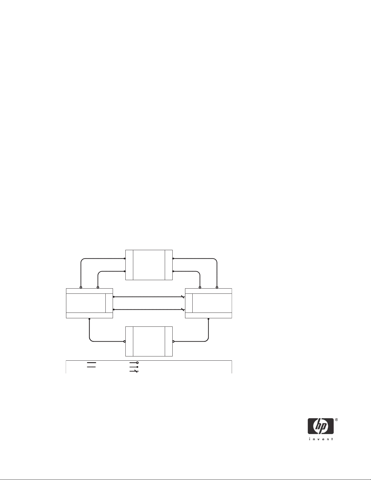
As shown in Figure 1, the CCI topology is as follows:
• In the Access Tier, a user accesses an available blade PC from a remote access device.
• In the Compute Tier, for a dynamic environment implementation, the Session Allocation Manager
allocates the user direct access to either a new or an existing blade PC session.
A new session consists of a user without either an active or disconnected remote desktop session
running on a blade PC within the CCI solution.
An existing session consists of a blade PC resource that is either:
• Actively hosting the user’s session from a different access device.
or
• A session that the user has disconnected from (either the same or different access device)
without first logging off.
• In the Resource Tier, users authenticate with the directory server each time they attempt to log onto
a blade PC. After successful authentication, users are logged onto the blade PC with access to the
resources in the Resource Tier allowed by their security level.
• The Management Tier is reserved for the tools necessary to manage the CCI solution, such as HP
Systems Insight Manager and the HP Rapid Deployment Pack.
4
Page 5
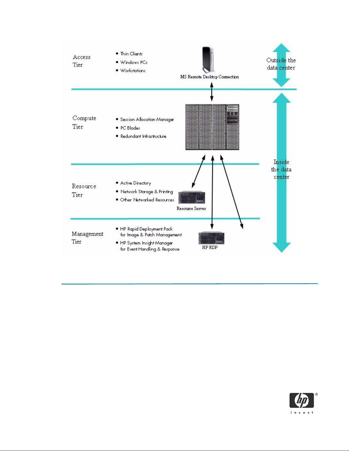
Figure 1 CCI topology
CCI, network speed, and the connection protocol
Network speed is really all about “how much longer than instantaneous does it take a signal to travel a
given route?” Anything more than instantaneous is “latency.” So, the question is how much latency is in a
network supporting CCI, and at what point does this latency impact user experience?
One of the advantages of CCI over competitive offerings and traditional computer systems is that the
remote host does not download files to the local access device. Instead, the remote host transmits only a
bitmap representation of the blade PC screen to the access device. Even at a dial-up network speed of 48
Kilobits per second (Kbps), you can open large files utilizing the blade PC almost instantly while viewing
them remotely. For example, if a user on a traditional system wants to open a 10-MB email attachment,
the user must launch an email application on the remote computer to gain access to email, and then literally wait for hours for the email attachment to download over a dial-up connection. This download of the
file to the remote computer introduces a security risk. Alternatively, the CCI solution allows the remote user
5
Page 6

to access a blade PC located in the corporate data center to run an email application and manipulate the
10-MB file without download the file to the remote access device. In this case, access to read and edit
such a file is achievable within a reasonably expected amount of time.
An understanding of the transport software used by CCI is imperative before trying to understand how
network latency can impact end users experience. The transport software used to move signals back and
forth between the access device and the blade PC in the data center is called the Remote Desktop Connection (RDC). This software uses Microsoft Remote Desktop Protocol (RDP) or any other remote desktop
connection client compatible with Microsoft Terminal Services.
RDP is a multi-channel protocol that allows you to connect to a computer running Microsoft Terminal Services. RDP software exists for most versions of Windows, as well as other operating systems such as Linux.
The first version of RDC (version 4.0), introduced with Terminal Services in Windows NT 4.0 Server, was
based on the ITU T.share protocol (T.128). Terminal Server Edition Version 5.0, introduced with Windows
2000 Server, included support for a number of features including localized printer support and was
intended to improve utilization of network bandwidth. Version 5.1 was introduced with Windows XP and
includes features such as support for 24-bit color and sound.
Microsoft’s Remote Desktop Protocol software is available as a free download for other Microsoft operating systems at: http://www.microsoft.com/downloads/details.aspx?FamilyID=33ad53d8-9abc-4e15-
a78f-eb2aabad74b5&DisplayLang=en).
You can find additional information about RDP at:
• Remote Desktop Protocol - from the Microsoft Developer Network
(http://msdn.microsoft.com/library/en-us/termserv/termserv/remote_desktop_protocol.asp)
• Understanding the Remote Desktop Protocol - from support.microsoft.com
(http://support.microsoft.com/default.aspx?scid=kb;EN-US;q186607)
• Remote Desktop Connection for Windows Server 2003 - latest version of Microsoft’s free client for
Windows 95 and upwards
(http://www.microsoft.com/downloads/details.aspx?displaylang=en&familyid=a8255ffc-
4b4a-40e7-a706-cde7e9b57e79)
• Remote Desktop Connection Client for Mac - Microsoft’s free client for Mac OS X
(http://www.microsoft.com/mac/otherproducts/otherproducts.aspx?pid=remotedesktopclient)
• rdesktop - free open source client for Unix platforms
(http://www.rdesktop.org/)
You can optimize RDP for a variety of connection speeds. For instance, You can define less rich color and
screen resolution to reduce network traffic. For more information about optimizing your RDP settings, reference Microsoft RDP settings for HP’s Consolidated Client Infrastructure Environment.
6
Page 7

CCI network traffic patterns
Traditional distributed PCs have historically created peak network traffic at specific times. Traffic traditionally peaks within the first 30 minutes of the workday as users log in and large amounts of data move
between the datacenter and end users. During this time, MS Exchange data, system hot fixes, etc.,
traverse the network. Afterward, network demand tends to drop substantially.
In contrast, because CCI computers (blade PCs) are powered on continuously in the datacenter under
control of the datacenter manager, there is a very different pattern of network traffic for the following reasons:
• All traditional network traffic from datacenter to distributed PC is internal to the datacenter.
• Data center managers deploy image updates including application updates, operating system ser-
vice packs, and hot fixes. Managers can schedule these updates at times when network traffic is low.
• Most datacenters have a higher capacity internal network infrastructure compared to the infrastruc-
ture between the datacenter and users.
• The typical CCI network traffic pattern from the datacenter to the user is very steady and much lower
than the peaks seen with traditional PCs. Instead of sending files to the user, CCI uses RDC to render
what the blade is doing on the user’s screen.
Based on CCI network observations, HP recommends the following guidelines for the number of active
users per network segment while providing a substantial buffer for extraordinary peaks in demand.
• 10,000 simultaneous active users per 1 Gigabit per second network segment.
• 1,000 simultaneous active users per 100 Megabits per second network segment.
• 100 simultaneous active users per 10 Megabits per second network segment.
While these are general guidelines that work for most infrastructures, differing circumstances and local
variables can require analysis on a case-by-case basis.
7
Page 8

Network reliability
Businesses require reliable networks, which are imperative to support solutions that successfully address
business needs. In CCI, network failure affects user access to virtualized desktops. Therefore, HP recommends that you use redundant design practices to provide multiple network paths to all centralized computing resources. Carefully set expectations of how minor to catastrophic network outages will affect the
end user environment. Consider customer business rules and job functions when establishing these expectations.
Network bandwidth
The term “bandwidth” in network design refers to the transfer data rate supported by a network connection or interface and is commonly expressed in terms of bits per second (bps). The term comes from the
field of electrical engineering, where bandwidth represents the total distance between the highest peak
and lowest valley of a communication signal (band). Network bandwidth is one of the only factors that
determines the perceived speed of a network.
Network latency
Network latency describes the time (in milliseconds) that it takes a packet to traverse a network. An easy
way to measure network latency is with the MS DOS “PING” command. This command tests any network
device that has a valid IP address. A successful ping yields a message displaying response time. Because
CCI end users access their blade PC sessions across some distance, maintaining low network latency has
a direct affect on user experience. A few factors that can increase network latency that you should consider when evaluating a CCI network include:
• poor quality connections
• network congestion
• network saturation
Consider conducting a network traffic study to determine the level of saturation a connection may encounter, and take steps (well documented outside the scope of this paper) to alleviate the underlying conditions.
8
Page 9

Connection methods
CCI end users can connect to their blade PC using a network in a variety of ways: traditional dial-up
modems, DSL, cable modems, LANs, etc. General performance with RDC (including CCI and any network architecture that uses MS-RDC) is based on response times as characterized in the following table:
Response Time
(Round Trip Ping)
<1 ms - 10 ms LANs or WANs No discernible latency; same experience as if the
10 ms - 20 ms Broadband modems/bridges
10 ms - 100 ms Busy LANs or WANs Some latency, but rarely discernible (might be detect-
100 ms - 200 ms Dial-up modems Discernible latency (for example, when rapidly scroll-
> 200 ms Congested Networks Substantial latency (for example, when rapidly scroll-
Typical Network Type End User Experience
user is using a traditional desktop PC (all other things
equal)
able if rapidly scrolling Power Point in full screen
mode, for example)
ing PowerPoint or typing quickly, screen updates
might not appear for a second or two). Reducing
screen resolution and color depth can improve end
user experience.
ing PowerPoint or typing quickly, letters might not
appear on the screen for several seconds or more,
scrolling text documents is “jumpy,” etc.). Using RDC
with latency exceeding 200ms is generally not a satisfactory experience.
Based on testing by the HP CCI team, the implications of users working off the corporate LAN and accessing the CCI from a remote location should yield the following experiences:
• Broadband users: The experience when connecting to a corporate WAN/LAN should be similar to
being connected directly to the corporate LAN with no noticeable latency. However, every network
and network connection is different, so other considerations such as congestion or poor connection
quality can impact the end user experience. All testing to date indicates that CCI performance across
broadband connections is very similar to being on a Local Area Network.
• Analog dial-up users: For users who connect to their corporate network using a analog dial-up
modem, round-trip latency of 100ms to 200ms is common, and latency higher than 200ms is not
unheard of. In this situation, CCI works well for reading email, working in spreadsheets, creating text
documents, etc. However, latency above 200ms can become an inhibitor when performing complex
tasks, such as creating PowerPoint documents or working with graphically intense applications. In
case-by-case scenarios where the remote user only has access to an analog connection, a higher
quality modem and/or custom modem initialization string might bring the latency down to a more
acceptable level. You should involve someone technically skilled at troubleshooting analog network
connections.
9
Page 10
• Additional considerations on dial-up modems: Analog modems vary in quality. Higher quality
56kbps modems may produce lower latency than lower quality modems. Because analog modems
are designed to retrain their speed depending on line condition, you may need to fine tune modem
configuration or seek a more robust method to access the network, such as an xDLS broadband connection or dedicated leased-line.
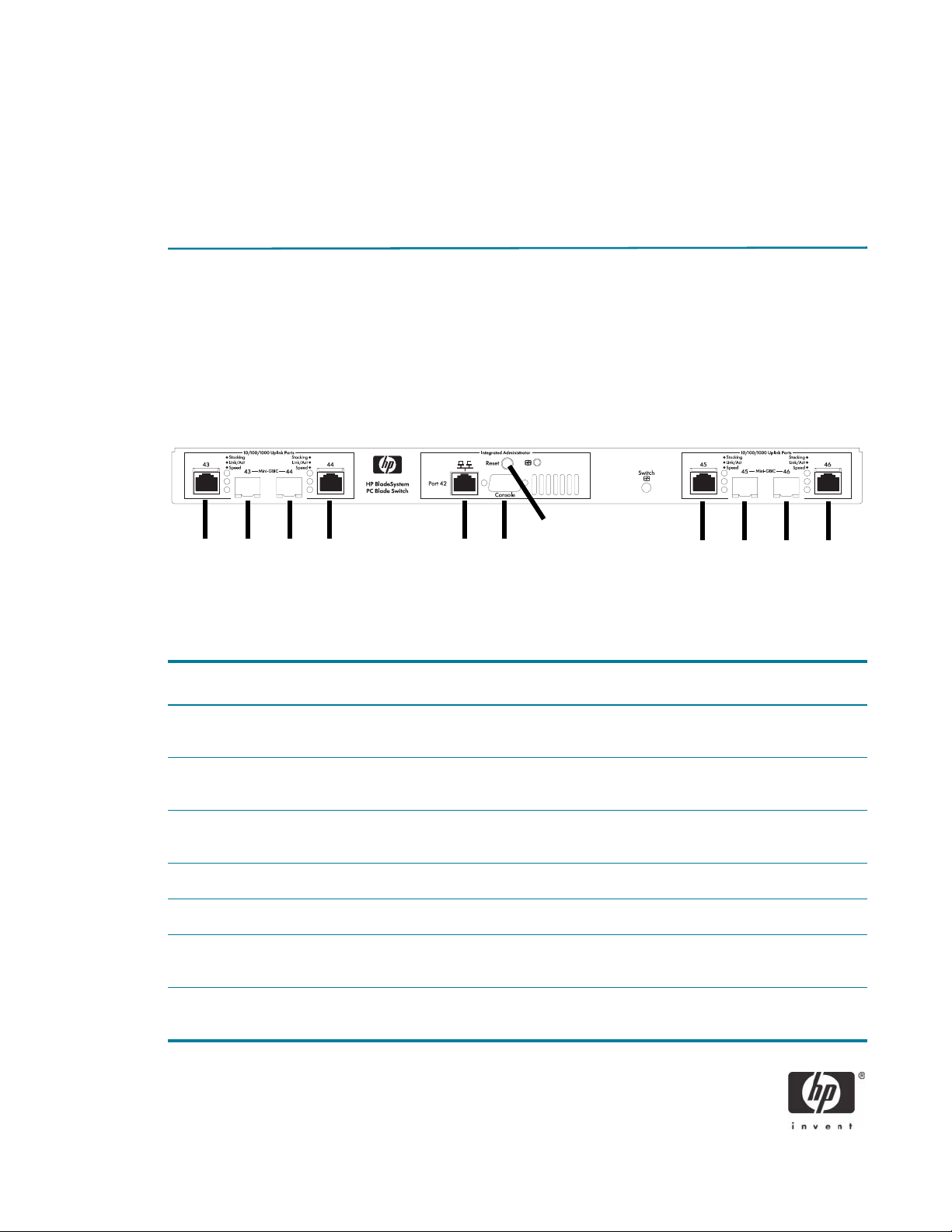
The HP BladeSystem PC Blade Switch
The HP PC Blade Switch is in the interconnect tray for the HP PC Blade Enclosure that uses a non-blocking,
managed Layer 2+ Ethernet switch (see Figure 2). The HP PC Blade Switch consolidates 40 Ethernet NICs
from blade PCs and provides four external dual personality (Copper or Fiber) Gigabit “uplink” Ethernet
ports. You can configure the HP PC Blade Switch to combine all Ethernet signals into one physical uplink
(see “Maximizing network cable reduction” on page 12) or up to four physical uplinks configured as a
single logical uplink using IEEE 802.3ad link aggregation (see “Link aggregation groups” on page 15).
7
1
2 3 4 5 6
8 9 10 11
Figure 2 HP PC Blade Switch tray external panel
Item Description
1, 4 RJ-45 Auto MDIX, 10/100/1000T Gigabit Ethernet Uplink Ports e43 and e44
(Assigned to VLAN 2 by default)
2, 3 Small Form-factor Pluggable (SFP) Port for Ethernet Uplink GBIC Connector to Ports e43 and e44
(Assigned to VLAN 2 by default)
5 RJ-45 Auto MDIX, 10/100T Fast Ethernet Uplink Port e42
(Assigned to VLAN 1 by default)
6 DB-9 RS-232 Serial Port for Integrated Administrator console access
7 Integrated Administrator Reset Button
8, 11 RJ-45 Auto MDIX, 10/100/1000T Gigabit Ethernet Uplink Ports e45 and e46
(Assigned to VLAN 1 by default)
9, 10 Small Form-factor Pluggable (SFP) Port for Ethernet Uplink GBIC Connector to Ports e45 and e46
(Assigned to VLAN 1 by default)
10
Page 11

Internal Ethernet ports
The HP PC Blade switch comes pre-configured with two Virtual LANs, VLAN 1 and VLAN 2. VLAN 1 is
assigned to odd numbered ports e1 through e39, which physically connect blade PC NIC A to the switch
by way of the passive centerwall assembly. Blade PC NIC A in bay 1 is connected to port e1 and blade
PC NIC A in bay 2 is connected to port e3 and so forth. VLAN 2 is assigned to even numbered ports e2
through e40, which physically connect blade PC NIC B to the switch by way of the passive centerwall
assembly. Blade PC NIC B in bay 1 is connected to port e2 and blade PC NIC A in bay 2 is connected
to port e4 and so forth. Port e41 internally connects the Integrated Administrator to VLAN 1 for IA-toSwitch Ethernet communication.
External Ethernet ports
The HP PC Blade Switch includes four external RJ-45 10/100/1000 Gigabit Ethernet “uplink” ports (e43
- e46) and one 10/100Mbps FastEthernet port (e42). Ports e43 - e46 are each partnered with a Small
Form-factor Pluggable (SFP) GBIC port. When the SFP port is in use, its RJ-45 counterpart is automatically
disabled.
By default, e43 and e44 are assigned to VLAN 2, while e42, e45 and e46 are assigned to VLAN 1.
These assignments provide segmented network support for blade PC NIC A and NIC B, which should
coincide with most CCI solution implementations. However, to meet customer-specific requirements for
CCI, the configuration can be changed.
Even though port e42 is assigned to VLAN 1, you can use the port for dedicated connectivity to a management network or for local administration and diagnostic tasks without unplugging a dedicated uplink.
Simultaneous management of the HP PC Blade Switch and the Integrated Administrator is possible using
this single port (or any other external Ethernet port). Although ideally suited for management, you can use
this port for other purposes, such as for additional network connectivity with reduced bandwidth.
NOTE: Pay careful attention if you use port e42 in a redundant scenario using spanning tree. Without
proper adjustment, port e42’s default spanning tree cost and priority give it the highest priority of all
external uplinks on the HP PC Blade Switch. If connected to the same spanning-tree topology as one or
more of the other uplinks, e42 is put into a forwarding state, while other uplink(s) are put into a blocking
(alternate) state. The switch will function normally, but with significantly reduced performance. Consider
adjusting either the cost or priority attributes to make this port operate as the alternate (blocking) path
when used in conjunction with any of the other uplink port(s).
Port speed, duplex, and flow control
The HP PC Blade Switch is configured by default to auto negotiate the port speed and duplex for all
uplink ports (e43-e46). Port speed has been pre-configured to 100Mbit and duplex has been set to Full
for ports (e1-e42). When making network design decisions, it is imperative to consider the settings of the
upstream switch, blade PCs, and data center policy.
HP recommends you manually configure and set the settings for any external uplink at deployment time:
• Port Speed - 1G
• Duplex - Full
• Flow Control - OFF
If you want to use the auto negotiate setting, HP recommends that you verify each of the parameters once
a connection is made to the upstream switch(es).
11
Page 12

Maximizing network cable reduction
For maximum cable reduction, consider using a combination of IEEE 802.1q VLAN Tagging and IEEE
802.3ad Link Aggregation. Using a LAG to carry the network traffic for all necessary VLANs over two
physical uplinks for each HP PC Blade Switch can reduce total uplink to as few as 28 Ethernet connections for a 42U rack fully populated with 14 HP PC blade Enclosures for a total of up to 560 network
adapters. If further cable reduction is necessary, consider oversubscription techniques. HP recommends a
thorough understanding of traffic load and demand before designing the CCI solution around these principles. Because not everyone uses CCI in the same manner and most networks are designed differently, it
is beyond the scope of this paper to explain individual traffic patterns for each component of the CCI
solution.
You can attempt to understand traffic load and demand by building the CCI solution using a greater number of uplinks and then performing a comprehensive bandwidth study of how each component of the
solution behaves based upon business and IT rule/policy requirements and practices.
Virtual Local Area Network (VLAN)
The HP PC Blade Switch supports 256 port-based IEEE 802.1Q VLANs with a maximum addressable
range of 4094. The switch also supports Group VLAN Registration Protocol (GVRP) for dynamic VLAN
registration. Members of a VLAN may be untagged or tagged according to IEEE 802.3ac VLAN Ethernet
frame extensions for 802.1Q tagging. Therefore, any HP PC Blade Switch VLAN may span other switches
that support 802.1Q tagging located within the network infrastructure.
Management IP
By default, the HP PC Blade Switch is configured to dynamically obtain an IP address using dynamic host
configuration protocol (DHCP) for each of its two pre-configured VLANs. If preferred, an administrator
can statically assign IP addresses through the Command Line Interface (CLI) or the Embedded Web System (EWS). However, if making the change remotely over the network they may need to reconnect with
the newly assigned IP address. For increased security, an administrator can specify the IP-based management stations that are allowed to access each switch or leverage additional access security protocols such
as SSH, AAA, RADIUS, or TACACS+.
Switch diagnostics
The HP PC Blade Switch option includes a removable Integrated Administrator module (see Figure 3). The
Integrated Administrator provides a single management console for the efficient management of the HP
PC Blade Enclosure and its accompanying blade PCs. This includes automatic health monitoring of the
switch with SNMP trap generation and system LED status.
External LEDs provide enclosure and switch status and link and speed on each Gigabit uplink connector
(see Figure 3). An emergency enclosure shut-down feature is included in case of critical system temperature caused by the switch or other enclosure component.
12
Page 13
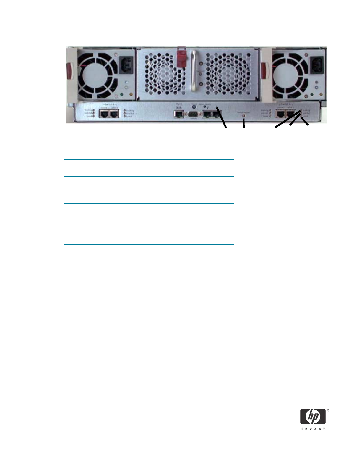
4
1
2
Figure 3 HP PC Blade Switch tray external panel LEDs
Item Description
1 Integrated Administrator Health
2 Interconnect Switch Health
3 Reserved for future use
4 Link Activity Status
5 Link Speed Status
The HP PC Blade Switch provides the following additional serviceability and diagnostic features:
3 5
• Port mirroring with the ability to mirror desired type of frames (egress, ingress, or both).
• Power on self test (POST) at boot for hardware verification.
• Monitoring port utilization, data packets received/transmitted, error packets, packet size, trunk utiliza-
tion, SNMP data, etc.
• Details of system information via the user interfaces such as port parameters and link status, switch
asset information, configuration values, log entries, etc.
• Ability to “ping” to test the connectivity on the Ethernet network.
• Local system log (syslog) with ability to view and clear messages that may be saved (uploaded) as
text file via TFTP.
• MAC addresses view, clear, and delete from the forwarding database for identifying problems with
MAC address learning and packet forwarding.
• Ability to maintain two separate valid firmware images, one active and one inactive.
For more detailed information on the administration capabilities of the Interconnect switch, see the HP
BladeSystem PC Blade Switch and HP BladeSystem PC Enclosure user guides.
13
Page 14

Switch management
The HP PC Blade Switch is an industry-standard managed Layer 2+ Ethernet switch, meaning users configure and manage the switch like other industry-standard Layer 2 Ethernet switches. To aid users during initial deployment, the switch includes a default configuration that is fully operational at initial boot (see
Appendix A). A basic CCI configuration should not require significant changes to the default settings.
However, HP highly that you review the default settings and apply any changes before connecting the
switch to a production network.
An Embedded Web System (EWS) and Command Line Interface (CLI) with scripting capability are
included in the switch firmware to aid with configuring, managing, and monitoring the switch. The switch
also supports Telnet, Simple Network Management Protocol (SNMP), Secure Socket Host (SSH), and
Remote MONitoring (RMON). You can disable, enable, configure, and monitor any combination of the
downlink and external uplink ports on a per port basis. Out-of-band or in-band (or both) access to the
switch management interfaces are supported locally and remotely from anywhere on the network. Administration of the switch is possible through any External Ethernet port as well as through the serial port by
way of the Integrated Administrator. By default, switch configuration interfaces are assigned to both
VLAN 1 and 2. VLAN 1 is externally accessible through from ports e42, e45, or e46. VLAN 2 is externally accessible through ports e43 or e44.
Embedded Web System interface
Users can access the EWS by using Internet Explorer or Netscape Navigator over a TCP/IP network (see
Figure 4). The EWS interface consists of three main sections:
• The Active Virtual Graphic provides real-time status of the switch front panel and the means to quickly
view statistics of individual ports.
• The Navigation Window contains items or features to select.
• The Administration Window contains options for viewing or altering switch information.
14
Page 15

Navigation Pane Administration Window
Figure 4 Browser-based interface for HP PC Blade Switch
Link aggregation groups
The HP PC Blade Switch complies with IEEE 802.3ad static and dynamic Link Aggregation Groups
(LAGs). The switch supports a maximum of eight multi-port trunks with up to eight ports per trunk.
IMPORTANT: Because the HP PC Blade Switch has only four physical uplinks, limit Link Aggregation to
a maximum of four physical trunk members for uplink ports. If you want to put the two blade PC NICs into
a LAG, a maximum of eight blade PCs can participate, assuming no external uplink ports are already
configured in a LAG. If all blade PCs need to run in a redundant NIC configuration, the Broadcom
Advanced Server Program (BASP) intermediate driver supports Smart Load Balancing for switch-independent, bidirectional, fault-tolerant teaming, and load balancing.
Spanning Tree
Spanning tree protocol eliminates layer 2 loops within a network. Without the aid of loop detection, looping broadcast packets would lead to severe network congestion, causing a broadcast storm. The sourcebased location method used to communicate between switches would cease to function properly, crippling switch-based networks. Therefore, all well-designed networks need alternate redundant paths to
help mitigate infrastructural component failure.
The HP PC Blade Switch supports IEEE 802.1D (STP), 802.1w (RSTP), and 802.1s (MSTP). In most cases,
you should use default parameters in CCI network design, such as cost and priority. By default, the switch
15
Page 16

ships with IEEE 802.1s pre-configured to use a special feature called PVST Interop Mode. This feature provides certain advantages specific to the CCI solution. Thorough knowledge of PVST Interop Mode is
required prior to designing the switch into an existing production network. For more information on PVST
Interop Mode, see “PVST interoperability mode” on page 16.
NOTE: Successfully implementing the Spanning Tree Protocol can be complicated and should only be
performed by a properly trained and qualified network specialist familiar with the HP PC Blade Switch. If
Spanning Tree is not properly configured on the HP PC Blade Switch or on any upstream network switches
that will participate in the Spanning Tree domain or region, spanning tree protocol may block unexpected ports causing sporadic or complete loss of network connectivity. The HP BladeSystem PC Blade
Switch ships from the factory pre-configured with IEEE 802.1s MSTP and PVST Interoperability mode.
Before changing any switch settings or connecting the HP PC Blade Switch to a production network,
please review “PVST interoperability mode” on page 16.
General notes regarding Spanning Tree
The default forward delay time associated with IEEE 802.1D is 15 seconds. Therefore, during a network
topology change, it may take from 30 to 45 seconds for a simple network to fully reconverge. A complex
network may take even longer. Therefore, a change in topology anywhere within the active (forwarding)
network topology may affect some network applications.
Symptom: A CCI user may experience a 30 - 45 second pause in blade PC responses to user request or
even a disconnection to their blade PC session during spanning tree reconvergence (topology change).
HP recommends using IEEE 802.1w (Rapid PVST) or IEEE 802.1s, as these protocols reconverge much
faster. When using the faster protocols, CCI users experience only a momentary pause while the spanning tree re-converges.
As recommended in the IEEE 802.1Q VLAN standard, when using 802.1D or 802.1w, a single spanning
tree is configured for all uplink ports across the HP PC Blade Switch, including those in separate VLANs.
Therefore, if redundant physical links exist in separate VLANs, spanning tree will block all but one of
those links. However, if you need to use spanning tree on the switch in a VLAN environment with redundant physical links, you can prevent blocked redundant links by using a LAG.
When considering how to best connect the HP PC Blade Switch to the enterprise infrastructure, you can
use one aggregation switch instead of two. While using spanning tree to build redundant links between
the HP PC Blade Switch and a single aggregation switch would work, it would be inefficient as one link
will always be blocked. In this alternate case, HP recommends implementing IEEE 802.3ad Link Aggregation. A LAG offers benefits such as SRC+DST MAC level load balancing and virtually instantaneous reconvergence if a physical link or port goes down.
PVST interoperability mode
This feature allows for specific types of interoperability with networks running Per-VLAN spanning tree protocols. This feature enables the HP PC Blade Switch to operate internally with MSTP and communicate
externally with other switches configured for either 802.1d or 802.1w Per-VLAN spanning tree protocols
without bridging Per-VLAN Root bridges from multiple VLAN instances or falling back configuring the HP
Blade Switch to operate with a legacy spanning tree operation such as 802.1xxxx.
When PVST interoperability mode is enabled, the switch translates Ingress BPDUs from both STP and
RSTP-enabled devices. The PVST interoperability feature translates the incoming BPDU to MSTP internally,
16
Page 17

which then assigns the traffic to the appropriate internal MSTP instance. Before transmitting outgoing or
uplink packets, the PVST interoperability feature translates the MSTP BPDU back to RSTP. This process
allows internal operation with MSTP and external operation with other Per-VLAN spanning tree protocols
to eliminate bridging multiple per-VLAN Root instances. When communicating with an 802.1D peer, the
BPDU transmission will fall back to 802.1D as per the specification of the standard.
This feature is intended for CCI deployments that require any of the following:
• Two (or more) VLAN configurations for the HP PC Blade Switch.
• Any network scenario where the HP PC Blade Switch will be used to conjoin different spanning tree
domains or instances. For example, Cisco PVST or Rapid PVST.
Please note that in this mode, all uplink ports are configured to operate only in Access mode. This configuration permits the use link aggregation capabilities but not 802.1q (VLAN tagging).
Non-PVST deployments may utilize the IEEE-based spanning tree protocols (classic, rapid, or Multi) along
with 802.1Q to achieve a highly redundant and fault tolerant configuration.
NOTE: When operating with PVST Interoperability Mode enabled, adding custom VLANs requires
assigning instances to internal MSTP Instances to keep them separated. The instance must be configured
to use the same MSTI for common spanning tree networks.
Disabling the spanning tree PVST Interoperability mode
To completely disable the PVST Interop feature and return the switch to a clean IEEE 802.1s MSTP environment, use the following commands at the CLI console prompt:
enable
configure
no spanning-tree mst mstp-rstp
spanning-tree mst configuration
instance 1 remove vlan 1
instance 2 remove vlan 2
instance 15 remove vlan 3-4093
exit
NOTE: Configure the spanning tree mode, VLAN settings, port configuration, and other relevant switch
parameters to match the remaining requirements of the infrastructure, including MST Instance 1 - 15
should be configured with a Priority of 6440. To use a different priority, further configuration may be necessary. Setting the priority to 32768 will remove references in the running configuration.
17
Page 18

SNMP and remote monitoring
You can monitor the HP PC Blade Switch remotely from an SNMP/RMON network management tool set
such as HP Systems Insight Manager (HP SIM) or HP OpenView. Unique integration with HP Systems
Insight Manager provides the following additional features:
• Pre-compiled switch MIB (HP SIM 5.0.2)
• Automatic identification upon discovery (HP SIM 5.0.2)
• Receive traps and events from the switches upon registration of MIBs and IA/Switch Configuration
Configuring the switch to send SNMPv1traps
Because HP SIM processes only SNMP V1 traps, you must configure the switch to send traps to HP SIM.
By design. HP SIM will discard any traps it receives from devices that are not in systems list.
The following is a very simple example of the minimal HP PC Blade Switch CLI command to configure
SNMP Support from the CLI of the HP PC Blade Switch SNMP trap destination to the server hosting HP
SIM. If the HP SIM server is located on a different IP subnet, the switch is configured with a configured
router as its default gateway. There are other attributes available for configuring SNMP traps. Please consult the
the
enable
configure
snmp-server host <IP Address of HP SIM> public 1
CLI Reference Guide: HP BladeSystem PC Blade Switch, or if you prefer to use the Web interface, see
Embedded Web System User Guide for the HP BladeSystem PC Blade Switch.
Configuring HP SIM to work with the switch
HP SIM 5.0.2
Beginning with HP SIM 5.0.2, the HP PC Blade Switch will be automatically recognized upon discovery.
The HP PC Blade Switch-specific MIB will be pre-compiled, but requires manual registration prior to
proper functionality. The following steps explain the MIB registration process for HP SIM 5.0.2.
1. From the HP SIM server, open a DOS command prompt window.
2. Change the current working directory to the HP SIM MIBS folder, which by default is c:\Program
Files\HP\Systems Insight Manager\mibs.
3. Execute the command: mxmib -a RADLAN-MIB.cfg
4. To verify RADLAN-MIB mib was loaded, execute the command: mxmib -l
5. Exit the DOS command prompt window.
18
Page 19

6. To verify that the SNMP traps are available and enabled in HP SIM:
• In HP SIM, select Options > Events > SNMP Trap Settings.
• Verify that the newly registered MIB file RADLAN-MIB.mib is in the Mib Name box.
NOTE: By default, the traps in this MIB may not be enabled for trap handling and severity because the
level is not configured. Review each trap and configure Enable Trap Handling and Severity based on
business requirements.
HP SIM 5.0.1 and earlier
For HP SIM to properly receive traps, you must manually install the HP PC Blade Switch-specific MIB and
one of its dependent MIBs. The following steps explain the MIB installation and registration process.
1. In HP SIM, select Options > Manage System Types.
2. Click New.
3. For the System object identifier, click Retrieve from system.
4. Set the Community string (for example, public).
5. Direct the target host name or IP address to the management address of the HP PC Blade Switch.
6. Click Get response. The Response value contains the results.
7. Click OK. Notice that the System object identifier field is populated.
8. Select the System type: (for example, to Switch)
9. Set the Product model to HP BladeSystem PC Blade Switch.
10. Click OK.
To create a configuration file:
1. From the HP SIM server, open a DOS command prompt window.
2. Change the current working directory to the HP SIM MIBS folder, which by default is c:\Program
Files\HP\Systems Insight Manager\mibs.
3. Copy the following files to HP SIM MIBS folder:
RADLAN-MIB.mib
snmpv2-smi-v1.mib
snmpv2-tc-v1.mib
4. At the DOS prompt, execute the command: mcompile RADLAN-MIB.mib
5. Verify that the “MIB Compilation completed successfully” message displays.
19
Page 20

Registering the configuration file with HP SIM:
1. Execute the command: mxmib -a RADLAN-MIB.cfg
2. To verify RADLAN-MIB mib was loaded, execute the command: mxmib -l
3. To verify that the SNMP traps are available and enabled in HP SIM:
• In HP SIM, select Options > Events > SNMP Trap Settings.
• Verify that the newly registered MIB file RADLAN-MIB.mib is in the Mib Name box.
NOTE: By default, the traps in this MIB may not be enabled for trap handling and severity because the
level is not configured. Review each trap and configure Enable Trap Handling and Severity based on
business requirements.
HP Session Allocation Manager (SAM)
The HP PC Session Allocation Manager (SAM) manages allocation of the RDP connection from a user’s
access device to the blade PC. Upon receipt of the user request for a blade PC, HP SAM checks for an
active or disconnected blade PC session allocated for that user. If one active session exists, the user is
reallocated that blade PC. Users without active blade PC sessions are allocated to an available blade PC.
To provide redundancy for the blade PC allocation function, HP SAM is installed on multiple servers that
share one central SQL database. Each of the HP SAM servers can manage and allocate shared blade
PCs. Once the HP SAM clients are configured to utilize the redundant HP SAM servers in the unlikely
event of an error condition causing the HP SAM server to not respond, the HP SAM client automatically
attempts to communicate with the next HP SAM server for the blade PC allocation (if configured to do so).
HP SAM minimum network requirements
• A simplified CCI deployment, the HP SAM server requires only one network connection.
• Network connectivity must exist between the HP SAM server and Active Directory server, SQL Server
database, blade PC, and Remote Access device.
20
Page 21

The blade PC allocation process
The following illustration highlights how HP SAM uses the network to facilitate the user to blade PC allocation process. Other HP SAM activities, such as manual or automated administrative operations to the
blade PC, may utilize the network, but are not necessarily covered in this illustration. For more information, see the HP PC Session Allocation Manager User Guide, part number: 416323-001.
Remote
Access
Device
6
Blade PC
1. Client sends HTTP “Connect Request” to HP SAM Web service (port 80 by default).
2. HP SAM validates the user name with directory services.
3. HP SAM retrieves user roles from SQL Server (port 1433 by default).
4. Users with more than one role are prompted to choose one.
5. HP SAM validates the blade PC using the HP SAM blade service.
6. HP SAM returns a blade PC pointer (new or disconnected) to the client (port 80 by default).
4
1
HP SAM
Server
57
2
8
Active
Directory
3
SQL
Database
7. Client connects to the blade PC (port 3389 by default).
8. Blade service sends usage activity (login, disconnected, logoff) to HP SAM (port 47777 by default).
Blade image management considerations
In a typical CCI implementation, blade PC image deployment and maintenance is accomplished with HP
Rapid Deployment Pack (RDP), which includes the Altiris Deployment Solution (DS). The network designer
has flexibility in determining where to deploy the DS server hosting HP RDP server within the network. For
more in-depth technical information regarding DS ports, protocols, switches and routers, PXE, and multicast, see Ports and Protocols used by Deployment Solution 6.5 at http://juice.altiris.com/node/249.
The HP blade PC supports Wake on LAN (WOL) and Pre-boot eXecution Environment (PXE) only on NIC
A. Therefore, when designing network connectivity for the HP RDP server to the blade PC, the HP PC
Blade Switch must be configured so that all internal odd numbered ports between e1 and e39 have network connectivity to the blade image management solution.
21
Page 22

The blade PC image PXE boot process
During the blade PC PXE boot process, the PXE server listens to communication between the blade PC
and the DHCP server, and then sends its IP address to the blade PC at the right moment. Once the blade
PC begins to boot, it knows the IP address to use to communicate with the PXE server.
DHCP Server
PXE Server
5
2
1
3
4
Blade PC
1. Blade PC requests (Discover) a new IP address from the DHCP server (UDP Port 68 to 67).
2. DHCP Server responds (Offer) by sending an available IP address to the blade PC (UDP Port 67 to
68).
3. PXE Server listens for DHCP Discover and Offer, and then sends its IP address to the blade PC (UDP
Por t 67 to 68) .
4. Blade PC sends confirmation message to DHCP Server (UDP Port 68 to 67).
5. DHCP Server sends acknowledgement of confirmation to client, and then provides additional informa-
tion if necessary (UDP Port 67 to 68).
CCI solution component dependencies
Each reference design includes the components that comprise the CCI solution. You can configure and
deploy CCI components in a variety of ways to satisfy customer-specific requirements. The need to separate components is typically deployment driven. The CCI solution is flexible enough to meet specific customer requirements, but there are some dependencies which you must consider during the design phase.
Each section identifies components and their dependencies.
• HP Session Allocation Manager
• Requires network access to Active Directory.
• Requires network access to Remote Access Device and blade PC.
• Requires network access to SQL database server.
22
Page 23

• HP Systems Insight Manager
• Requires network access to HP blade PC.
• Requires network access to SQL database server.
• HP Rapid Deployment Pack
• Participates in DHCP communication between blade PC NIC A and the DHCP server to facilitate PXE.
• If DNS is not available, the PXE boot image LMHOST file is required to be configured with IP
address to the HP RDP server.
• Requires image file shares to be accessible to blade PC after PXE boot.
• Requires network access to SQL database server.
• Remote Access Devices
• Requires network access to HP SAM server and blade PC.
• Manage client image from RDP server (Optional).
• Network access to NAS (Optional).
• HP PC Blade Enclosure Integrated Administrator and HP PC Blade Switch
• Network access to HP SIM.
• Network path to management station (Optional).
•DHCP (Optional).
• DNS (Optional).
• NTP (Optional).
• HP blade PC
•Requires network access to NAS.
•Requires network access to HP SAM.
•Requires network access to HP SIM.
• Requires network access to HP RDP through NIC 1.
• Requires network access to Active Directory.
General notes regarding solution Components
If you use CCI network designs with two VLANs, user data network storage can exist on either VLAN.
When working with routed network resources, Windows XP will try to use the first bound IP gateway even
if a second gateway is available. Accessing user data through the NIC bound second requires careful
design consideration.
23
Page 24

CCI network topology reference designs
HP designed the HP PC Blade Switch for deployment into a variety of different network topologies. This
section presents a set of sample network scenarios listed in order of least to most complex that illustrates
HP PC Blade Switch deployment examples within a CCI design. Each sub-section includes a high level
technical illustration of the network connectivity between the HP PC Blade Switch, the aggregation switch
layer, and if applicable, the core switch layer. These examples cover the most common network scenarios
encountered when making network design considerations for the CCI solution. Each section includes
notes based on HP test results.
As you step through each scenario in this section, each successive solution demonstrates greater solution
complexity and thus greater flexibility. For optimal comprehension and exposure to how spanning tree
operates, HP recommends that you read through each network scenario sequentially, beginning with
“Flat network” on page 24.
Appendix A contains the running configuration for each example that this section describes.
Flat network
Aggregation Switchp1
e43 e46
HP PC Blade
Switch
e45 e44
VLAN 1 Blade PC Image Management, PXE, DHCP,
Remote Access Devices, HP SAM, HP SIM,
Network Storage, DHCP, DNS, Active Directory
Physical Link
Logical Link
(VLAN 1)
A
Forwarding to Root
Forwarding Designated
(Alternate) Blocking
Description
• VLAN 1 assigned to all odd ports in the range e1 - e39 & e45
This reference design illustrates how the HP PC Blade switch may fit into any flat network without having
to change the default settings. By default, ports e42, e45, and e46 have been configured as access ports
assigned to VLAN 1. Link A connects port e45 (VLAN 1) to port p1 on the aggregation switch. Ports e43
and e44 (VLAN 2) are not connected. The VLAN 2 switch interface and blade PC NIC B will not obtain
a dynamically-assigned IP address. In this example, all aspects of the CCI solution involving the blade PC
will use NIC A. In this flat network design, blade PC NIC B is not part of this design.
Solution Component Considerations
• All CCI solution components are required to be accessible over VLAN 1.
24
Page 25

Networking Considerations
• You can deploy the HP PC Blade Switch into this scenario without changing the default switch config-
uration.
• Works with any network infrastructure that not require IEEE 802.1q VLAN Tagging on the HP Blade
PC Switch uplinks. If 802.1a VLAN tagging is required, some features of the HP PC Blade will require
configuration.
• To facilitate blade PC connectivity including image management, PXE, WOL, user and data accessi-
bility, and manageability, use one or more uplinks assigned to VLAN 1.
• Port e42 is only capable of 10/100 FastEthernet connectivity. You can use it as the sole uplink, but
network throughput to each enclosure will be a 100. If a Gigabit port is available on the aggregate
switch, HP recommends using one or more of the available HP Blade Switch uplinks for optimum network traffic flow.
• Optionally, with minimal effort, you can configure ports e45 and e46 for IEEE 802.3ad Link Aggre-
gation to combine the two ports into one logical 2Gb LAG uplink. Link aggregation provides additional network bandwidth as and physical link redundancy. You can reconfigure ports e43 and/or
e44 to be included in VLAN 1 and add them to the LAG, forming an even more robust connection.
For more information, see the following guides:
• Embedded Web System User Guide for the HP BladeSystem PC Blade Switch, part number
413353-002.
• Command Line Interface Reference Guide HP BladeSystem PC Blade Switch, part number
413354-002.
Redundant connectivity with IEEE 802.1D or 802.1w
(VLAN 101 & 102) (VLAN 101 & 102)
AB
p1
ProCurve 2824
Aggregation Switch 1
p21
Physical Link
Logical Link
p2
DE
(VLAN 101 & 102) (VLAN 101 & 102)
Forwarding to Root
Forwarding Designated
(Alternate) Blocking
Description
• VLAN 101 assigned to all odd ports e1 - e39, e43 & e45
• VLAN 102 assigned to all even ports e2 - e40, e43 & e45
ProCurve 2824
Core Switch
Root
C
(VLAN 101 & 102)
HP PC Blade
Switch
p2p1
p2
e45e43
VLAN 101 Blade PC Image Management, PXE, DHCP,
VLAN 1 02 Remote Access Devices, HP SA M, HP SIM,
Netwo rk Sto rage, D HCP, DN S, Activ e Directo ry
p1
ProCurve 2824
Aggregation Switch 2
p21
25
Page 26

This reference design illustrates how you can configure two or more physical connections to redundantly
deploy the HP PC Blade Switch. IEEE 802.1q VLAN tagging is in use so that while link E is blocked, link
D will carry traffic for both VLANs. If either link A & C or D were to fail, link E would take over.
This design’s logic works the same for either IEEE 802.1D or 802.1w. The difference is that 802.1w
reconvergence is much faster and is the preferred choice for these two protocols.
Network Considerations
• When configuring the HP PC Blade Switch for IEEE 802.1D or 802.1w operation, disable the PVST
Interop feature before changing the spanning tree mode to either STP or RSTP (see “Disabling the
spanning tree PVST Interoperability mode” on page 17).
• Optionally, you can use IEEE 802.3ad Link Aggregation in various combinations with this example
topology to enhance performance and link level redundancy.
• To maintain optimum network performance after a network failover, consider creating two LAGs, one
with ports e43 & e44, the other with ports e45 & e46.
• Since most well designed networks rarely fail, a disaster recovery scheme could comprise a LAG
made up of ports e43 - 46 with port e42 functioning as the failover link. If the primary network path
did fail, network connectivity would continue over port e42 (100mbps), and then continue to operate
with degraded performance until the primary connection is restored. The LAG can be comprised of
two to four uplinks in any order. Port e42 can never be a member of a LAG.
Flat network with Per-VLAN Spanning Tree
AB
0/1
Cisco 2960G
Aggregation Switch 1
0/21
DE
Physical Link
Logical Link
(VLAN 101) (VLAN 101)
0/2
Forwarding to Root
Forwarding Designated
(Alternate) Blocking
Cisco 6500
Core Switch
Root
C
(VLAN 101)
HP PC Blade
Switch
1/21/1
0/2
e46e45
(VLAN 101 to 1)(VLAN 101 to 1)
VLAN 101 Blade PC Image Management, PXE, DHCP,
Remote Access Devices, HP SAM, HP SIM,
Network Storage, DHCP, DNS, Active Directory
0/1
Cisco 2960G
Aggregation Switch 2
0/21
Description
• The default VLAN 1 on the HP PC Blade Switch is used in this example.
• VLAN 1 is untagged on all odd ports e1 - e39, e45 & e46.
26
Page 27
This reference design illustrates how you could deploy the HP PC Blade Switch into a network where
802.1q is not necessary and only one blade PC NIC is used. If either link A & C or D were to fail, link E
would take over.
Solution Component Considerations
All CCI solution components are accessible over VLAN 1.
Network Considerations
• You can deploy the HP PC Blade Switch into this scenario without making changes to the default con-
figuration.
• For Cisco networks, links A, B, and C may use either 802.1q or ISL.encapsulation.
• Optionally, you can use IEEE 802.3ad Link Aggregation in various combinations with this sample
topology to enhance performance and link level redundancy.
If you want to maintain optimum network performance after a network failover occurs, consider
creating two logical LAGs, one with ports e43 & e44, the other with ports e45 & e46.
Since a well designed network rarely fails, you could configure the primary forwarding connection to
include ports e43 - 44 and either port e45 or e46 to a single high performance link. You could use
the remaining FastEthernet port (e42) as the failover link that will operate with degraded performance
when active.
• Since only one VLAN is in use, making this scenario work does not require the PVST Interop feature.
Therefore, if you want IEEE 802.1q VLAN tagging, you must disable the feature before you can configure uplinks for Trunk mode operation.
Basic connectivity with per-VLAN Spanning Tree
(VLAN 101)
AB
0/1
Cisco 2960G
Aggregation Switch 1
0/21
DE
Physical Link
Logical Link
(VLAN 102)
0/2
Forwarding to Root
Forwarding Designated
(Alternate) Blocking
Cisco 6500
Core Switch
Root for all VLANs
(VLAN 101)
C
(VLAN 102)
HP PC Blade
Switch
1/11/1
e45e43
VLAN 1 Blade PC Image Management, PXE, D HCP,
VLAN 2 Remote Access Devices, HP SAM, HP SIM,
Network Storage, DHCP, DNS, Active Directory
Description
• VLAN 1 assigned to all odd ports e1 - e39 & e45.
• VLAN 2 assigned to all even ports e2 - e40 & e43.
(VLAN 101)
(VLAN 102)
0/2
(VLAN 101 to 1)(VLAN 102 to 2)
0/1
Cisco 2960G
Aggregation Switch 2
0/21
27
Page 28

This reference design illustrates how you can deploy the HP PC Blade Switch into a network without initially connecting the switch in a redundant fashion. This “staging” method allows you to quickly deploy
switches, giving you time to evaluate the solution. When you want redundancy, you can connect link e44
and e46 (see the next section for an example.) If either link A & C or D were to fail, link E would take
over.
Network Consideration
• You can deploy the HP PC Blade Switch into this scenario without making changes to the default con-
figuration.
• For Cisco networks, when running PVST/PVST+, links A, B, and C may use either 802.1q or
ISL.encapsulation.
• Optionally, you can use IEEE 802.3ad Link Aggregation in various combinations to enhance perfor-
mance and link level redundancy.
• If you want VLAN Load Balancing, you can use additional uplinks. See the next section for details.
Redundant connectivity with per-VLAN Spanning Tree
(VLAN 101)
Cisco 6500
1/1 1/2
(VLAN 102) (VLAN 102)
AB
0/1
Cisco 2960G
Aggregation Switch 1
0/21
FG
(VLAN 101 to 1) (VLAN 102 to 2)
Physical Link
Logical Link
0/2
0/22
DE
(VLAN 102 to 2) (VLAN 101 to 1)
Forwarding to Root
Forwarding Designated
(Alternate) Blocking
Core Switch
Root for all VLANs
(VLAN 101)
C
(VLAN 102)
e43 e46
HP PC Blade
Switch
e45 e44
VLAN 1 Blade PC Image Management, PXE, D HCP,
VLAN 2 Remote Access Devices, HP SAM, HP SIM,
Network Storage, DHCP, DNS, Active Directory
(VLAN 101)
Cisco 2960G
0/2
Aggregation Switch 2
0/21
0/1
0/22
Description
• VLAN 1 assigned to all odd ports e1 - e39, e45 & e46.
• VLAN 2 assigned to all even ports e2 - e40, e43 & e44.
This reference design illustrates how four uplinks can connect the HP PC Blade Switch to two separate
aggregation switches forming a fully redundant network. If either link A & C or D were to fail, link E
would take over. HP recommends starting with this example for Cisco networks using PVST/PVST+ where
you want switch-based redundancy. If either link A & C or D were to fail, link E and G would take over.
28
Page 29

Network Considerations
• You can deploy the HP PC Blade Switch into this scenario without making changes to the default con-
figuration.
• For Cisco networks running PVST/PVST+, links A, B, and C may use either 802.1q or ISL.encapsula-
tion.
• IEEE 802.3ad Link Aggregation is not available in this scenario.
• You can achieve VLAN Load Balancing by reversing the links at the aggregation layer for links E and
F. Optimal load balancing may depend upon the configuration of the rest of the network, and further
optimization may require addition configuration.
• For large deployments, 802.1w may be a better option because the same type of redundancy can be
achieved with two instead of four uplinks.
Standards based redundancy with IEEE 802.1s (MSTP)
(MSTI 1)
AB
0/1
Cisco 2960G
Aggregation Switch 1
0/21
DE
(MSTI 1)
Physical Link
Logical Link
Cisco 6500
Core Switch
Root for all MSTI s
(MSTI 2)
(MSTI 1)
0/2
(MSTI 2) (MSTI 2)
Forwarding to Root
Forwarding Designated
(Alternate) Blocking
C
(MSTI 2)
HP PC Blade
Switch
1/21/1
e45e43
VLAN 101 Blade PC Image Management, PXE, DHCP,
VLAN 102 Remote Access Devices, HP SAM, HP SIM,
Network Storage, DHCP, DNS, Active Directory
(MSTI 1)
(MSTI 2)
0/2
(MSTI 1)
0/1
Cisco 2960G
Aggregation Switch 2
0/21
Description
• VLAN 101 assigned to all odd ports e1 - e39 & e45.
• VLAN 102 assigned to all even ports e2 - e40 & e43.
This reference design illustrates how the use of IEEE 802.1s has benefits of performance optimization
through VLAN load balancing in addition to redundancy over fewer connections. MSTP is relatively difficult to implement and manage in large networks. In cases where you want MSTP but it is not currently
deployed, consider using it in an isolated spanning tree region. MSTP is backward-compatible with older
protocols and can co-exist fairly easily. If either link A & C or D were to fail, link E would take over.
Network Considerations
• When configuring the HP PC Blade Switch for IEEE 802.1s operation, disable the PVST Interop fea-
ture (see “Disabling the spanning tree PVST Interoperability mode” on page 17).
29
Page 30

• Optionally, you can use IEEE 802.3ad Link Aggregation in various combinations with this sample
topology to enhance performance and link level redundancy.
If you want to maintain optimum network performance after a network failover occurs, then consider
creating two logical LAGs, one with ports e43 & e44, the other with ports e45 & e46.
Since a well designed network rarely fails, you could configure the primary forwarding connection to
include ports e43 - 44 and either port e45 or e46 to for a single high performance link. You could
use the remaining FastEthernet port (e42) as the failover link that will operate with degraded
performance when active.
• Consider using VLAN Load Balancing to separate VLAN traffic and optimize performance. When
designing a disaster recovery scheme, consider using two additional uplinks to achieve VLAN Load
Balancing across dual core networks.
VLAN load balancing with IEEE 802.1s (MSTP)
(MSTI 1)
AB
0/1
Cisco 2960G
Aggregation Switch 1
Root for MSTI 1
0/21
DE
(MSTI 1)
Physical Link
Logical Link
Cisco 6500
Core Switch
(MSTI 2)
(MSTI 1)
0/2
(MSTI 2) (MSTI 2)
Forwarding to Root
Forwarding Designated
(Alternate) Blocking
C
(MSTI 2)
HP PC Blade
Switch
1/21/1
e45e43
VLAN 101 Blade PC Image Management, PXE, DHCP,
VLAN 102 Remote Access Devices, HP SAM, HP SIM,
Network Storage, DHCP, DNS, Active Directory
(MSTI 1)
(MSTI 2)
Aggregation Switch 2
0/2
(MSTI 1)
0/1
Cisco 2960G
Root for MSTI 2
0/21
Description
• VLAN 101 assigned to all odd ports e1 - e39, e43 & e45.
• VLAN 102 assigned to all even ports e2 - e40, e43 & e45.
This reference design illustrates how VLAN Load balancing with IEEE 802.1s reduces the number of physical links required to redundantly deploy the HP PC Blade Switch. Wherever possible, MSTP is the recommended choice for use with the CCI solution. If either link A & C or D were to fail, link E would take over.
Network Considerations
• When configuring the HP PC Blade Switch for IEEE 802.1s operation, disable the PVST Interop fea-
ture (see “Disabling the spanning tree PVST Interoperability mode” on page 17)
• Instances may be blocked in a slightly different manner on ProCurve Switch based networks. This is
due to the Auto port cost feature on those switches and does not mean that there is a problem with
the spanning tree. For example, on a ProCurve based network running MSTP using default spanning
30
Page 31

tree attributes, Instance 1 & 2 for link A, B, D, and E should be blocked at the core and at the HP PC
Blade Switch instead of at the aggregation switches.
• Optionally, you can use IEEE 802.3ad Link Aggregation in various combinations with this sample
topology to enhance performance and link level redundancy.
If you want to maintain optimum network performance after a network failover has occurred,
consider creating two logical LAGs, one with ports e43 & e44, the other with ports e45 & e46.
Since a well designed network rarely fails, you could configure the primary forwarding connection to
include ports e43 - 44 and either port e45 or e46 to for a single high performance link. You could
use the remaining FastEthernet port (e42) as the failover link that when active will operate with
degraded performance.
• When designing complex disaster recovery networks that use multiple cores, an additional layer of
aggregation switches could be connected over the two remaining uplinks.
For more information
For additional information, refer to the resources detailed below.
Resource Description Web address
HP ProLiant Essentials Rapid Deployment Pack home
page
HP Consolidated Client Infrastructure home page http://www.hp.com/go/cci
HP bc1500 blade PC home page http://www.hp.com/go/bladepc
HP SIM http://www.hp.com/go/hpsim
HP OpenView http://www.hp.com/go/openview
Embedded Web System User Guide for the HP BladeSystem PC Blade Switch, part number: 413353-002
CLI Reference Guide: HP BladeSystem PC Blade
Switch, part number: 413354-002
Installation Guide: HP BladeSystem PC Blade Switch,
part number: 413355-001
HP ProLiant BL e-Class C-GbE Interconnect Switch
Command Line Interface Reference Guide, part num-
ber: 322857-001
http://www.hp.com/servers/manage
http://h20000.www2.hp.com/bc/docs/support/SupportManual/c00687582/c00687582.pdf
http://h20000.www2.hp.com/bc/docs/support/SupportManual/c00687574/c00687574.pdf
http://h20000.www2.hp.com/bc/docs/support/SupportManual/c00692805/c00692805.pdf
http://h20000.www2.hp.com/bc/docs/support/SupportManual/c00594285/c00594285.pdf
31
Page 32

Resource Description Web address
HP ProLiant BL e-Class C-GbE Interconnect Switch
Menu-driven Interface Reference Guide, part number:
322858-001
HP ProLiant BL e-Class C-GbE Interconnect Switch
User Guide, part number: 263682-002
ProLiant BL e-Class C-GbE Interconnect Switch Overview white paper, part number: 16LD-0602A-
WWEN
http://h20000.www2.hp.com/bc/docs/support/SupportManual/c00594288/c00594288.pdf
http://h20000.www2.hp.com/bc/docs/support/SupportManual/c00594291/c00594291.pdf
http://h20000.www2.hp.com/bc/docs/support/SupportManual/c00098518/c00098518.pdf
Appendix A: HP PC Blade Switch startup-config samples
You can copy and save any of the following example startup-config examples to an ASCII text file, and
then copy the file to the switch using TFTP. Be sure to overwrite ‘startup-config’ when copying over the new
file. To save time deploying complex configurations, you can edit any of these samples to use additional
features. Remember to test your new configuration in a “sand box” environment before deploying to a
production network. Once you have overwritten the ‘startup-config’, you must restart the switch.
NOTE: You may need to make additional changes to your configuration settings. Some additional
changes may be specific to requirements not covered by these examples.
32
Page 33

Default (canned startup-config)
This sample will perform the following action against a default configuration:
• Loading this sample has the same affect as erasing the startup-config, and then restarting the switch.
spanning-tree mode mstp
spanning-tree mst mstp-rstp
interface range ethernet e(1-41)
spanning-tree disable
exit
spanning-tree mst configuration
instance 1 add vlan 1
instance 2 add vlan 2
instance 15 add vlan 3-4093
exit
spanning-tree mst 1 priority 61440
spanning-tree mst 2 priority 61440
spanning-tree mst 3 priority 61440
spanning-tree mst 4 priority 61440
spanning-tree mst 5 priority 61440
spanning-tree mst 6 priority 61440
spanning-tree mst 7 priority 61440
spanning-tree mst 8 priority 61440
spanning-tree mst 9 priority 61440
spanning-tree mst 10 priority 61440
spanning-tree mst 11 priority 61440
spanning-tree mst 12 priority 61440
spanning-tree mst 13 priority 61440
spanning-tree mst 14 priority 61440
spanning-tree mst 15 priority 61440
vlan database
vlan 1-2
exit
interface range ethernet
e(1,3,5,7,9,11,13,15,17,19,21,23,25,27,29,31,33,35,37,39,41-42,45-46)
switchport access vlan 1
exit
interface range ethernet
e(2,4,6,8,10,12,14,16,18,20,22,24,26,28,30,32,34,36,38,40,43-44)
switchport access vlan 2
exit
interface vlan 1
ip address dhcp
exit
interface vlan 2
ip address dhcp
exit
snmp-server community public ro view Default
33
Page 34

No STP (canned startup-config)
This sample will perform the following actions against a default configuration:
• Disable PVST Interoperability mode
• Disable MSTP
• Remove VLAN 1 from MSTI 1
• Remove VLAN 2 from MSTI 2
• Remove VLAN 3-4093 from MSTI 15
• Remove all MSTI priorities
• Disable Spanning Tree
• All other values remain in factory default
no spanning-tree
vlan database
vlan 1-2
exit
interface range ethernet
e(1,3,5,7,9,11,13,15,17,19,21,23,25,27,29,31,33,35,37,39,41-42,45-46)
switchport access vlan 1
exit
interface range ethernet
e(2,4,6,8,10,12,14,16,18,20,22,24,26,28,30,32,34,36,38,40,43-44)
switchport access vlan 2
exit
interface vlan 1
ip address dhcp
exit
interface vlan 2
ip address dhcp
exit
snmp-server community public ro view Default
34
Page 35

STP/RSTP (canned startup-config)
This sample will perform the following actions against a default configuration:
• Disable PVST Interoperability mode
• Disable MSTP
• Remove VLAN 1 from MSTI 1
• Remove VLAN 2 from MSTI 2
• Remove VLAN 3-4093 from MSTI 15
• Change all MSTI priorities to 32768
• Enable STP mode (IEEE 802.1D)
• All other values remain in factory default
interface range ethernet e(1-41)
spanning-tree disable
exit
vlan database
vlan 1-2
exit
interface range ethernet
e(1,3,5,7,9,11,13,15,17,19,21,23,25,27,29,31,33,35,37,39,41-42,45-46)
switchport access vlan 1
exit
interface range ethernet
e(2,4,6,8,10,12,14,16,18,20,22,24,26,28,30,32,34,36,38,40,43-44)
switchport access vlan 2
exit
interface vlan 1
ip address dhcp
exit
interface vlan 2
ip address dhcp
exit
snmp-server community public ro view Default
NOTE: You can use this example to set IEEE 802.1w functionally by running the following command
once the file has been activated on the switch.
Enable
Configure
Spanning-tree mode rstp
End
Save running-config startup-config
35
Page 36

MSTP (canned startup-config)
This sample will perform the following actions against a default configuration:
• Disable PVST Interoperability mode
• Remove VLAN 3-4093 from MSTI 15
• Change all MSTI priorities to 32768
• All other values remain in factory default
spanning-tree mode mstp
interface range ethernet e(1-41)
spanning-tree disable
exit
spanning-tree mst configuration
instance 1 add vlan 1
instance 2 add vlan 2
name cci
revision 1
exit
vlan database
vlan 1-2
exit
interface range ethernet
e(1,3,5,7,9,11,13,15,17,19,21,23,25,27,29,31,33,35,37,39,41-42,45-46)
switchport access vlan 1
exit
interface range ethernet
e(2,4,6,8,10,12,14,16,18,20,22,24,26,28,30,32,34,36,38,40,43-44)
switchport access vlan 2
exit
interface vlan 1
ip address dhcp
exit
interface vlan 2
ip address dhcp
exit
snmp-server community public ro view Default
NOTE: You will need to change the MST Name and Revision to match the rest of the network. Check with
your network administrator.
Flat network
Use the switch default settings.
36
Page 37

Redundant connectivity with IEEE 802.1D or 802.1w
interface range ethernet e(1-41)
spanning-tree disable
exit
spanning-tree mst configuration
instance 1 add vlan 101
instance 2 add vlan 102
instance 15 add vlan 3-100,103-4093
name cci
revision 1
exit
spanning-tree mst 1 priority 61440
spanning-tree mst 2 priority 61440
spanning-tree mst 3 priority 61440
spanning-tree mst 4 priority 61440
spanning-tree mst 5 priority 61440
spanning-tree mst 6 priority 61440
spanning-tree mst 7 priority 61440
spanning-tree mst 8 priority 61440
spanning-tree mst 9 priority 61440
spanning-tree mst 10 priority 61440
spanning-tree mst 11 priority 61440
spanning-tree mst 12 priority 61440
spanning-tree mst 13 priority 61440
spanning-tree mst 14 priority 61440
spanning-tree mst 15 priority 61440
vlan database
vlan 101-102
exit
interface range ethernet
e(1,3,5,7,9,11,13,15,17,19,21,23,25,27,29,31,33,35,37,39,41-42)
switchport access vlan 101
exit
interface range ethernet e(43-46)
switchport trunk allowed vlan add 101
exit
interface range ethernet
e(2,4,6,8,10,12,14,16,18,20,22,24,26,28,30,32,34,36,38,40)
switchport access vlan 102
exit
interface range ethernet e(43-46)
switchport trunk allowed vlan add 102
exit
interface vlan 101
ip address dhcp
exit
interface vlan 102
ip address dhcp
exit
snmp-server community public ro view Default
37
Page 38

NOTE: You can use this example to set IEEE 802.1w functionally by running the following command
once the file has been activated on the switch.
Enable
Configure
Spanning-tree mode rstp
End
Save running-config startup-config
Flat Network with Per-VLAN Spanning Tree
Use the default switch settings.
Basic Connectivity with Per-VLAN Spanning Tree
Use the default switch settings.
Redundant Connectivity with Per-VLAN Spanning Tree
Use the default switch settings.
38
Page 39

Standards Based Redundancy with IEEE 802.1s (MSTP)
spanning-tree mode mstp
interface range ethernet e(1-41)
spanning-tree disable
exit
spanning-tree mst configuration
instance 1 add vlan 101
instance 2 add vlan 102
name cci
revision 1
exit
interface range ethernet e(43-46)
switchport mode trunk
exit
vlan database
vlan 101-102
exit
interface range ethernet
e(1,3,5,7,9,11,13,15,17,19,21,23,25,27,29,31,33,35,37,39,41-42)
switchport access vlan 101
exit
interface range ethernet e(43-46)
switchport trunk allowed vlan add 101
exit
interface range ethernet
e(2,4,6,8,10,12,14,16,18,20,22,24,26,28,30,32,34,36,38,40)
switchport access vlan 102
exit
interface range ethernet e(43-46)
switchport trunk allowed vlan add 102
exit
interface vlan 101
name Private
exit
interface vlan 102
name Public
exit
snmp-server community public ro view Default
NOTE: Because IEEE 802.1q is being used, you will most likely need to change the VLANs to match
what the network administrator has provided.
VLAN Load Balancing with IEEE 802.1s (MSTP)
Use the same sample from above.
39
Page 40

Appendix B: Running the HP PC Blade Switch and the C-GbE
Interconnect Switch in a co-existing network
This appendix provides information about adding an HP BladeSystem PC Blade Switch to a network using
the C-GbE Interconnect Switch.
Both switches can function together on the same network. The HP PC Blade Switch is specifically designed
to work with the HP blade PC family of products, but can also work with the older ProLiant e-class Blade
Server product family. The HP PC Blade Switch is comprised of a single switch, instead of two switches
like the C-GbE. The HP PC Blade Switch supports many newer features not found in the C-GbE switch. As
a result, you can deploy the HP PC Blade Switch into networks that need to take advantage of the newer
feature.
You should not replace the C-GbE switch with the HP PC Blade Switch without first understanding that
both switches are different, and that you must fully understand the differences prior to deployment of the
new switch. Start by documenting how the target switch is used on the network, and then mimic that configuration in the new switch. When designing the new switch into your present solution, consider that most
commands and methods will not be consistent between the switches.
Before you deploy
Please configure and test the switch before connecting to a production network. You must understand the
CCI infrastructure prior to determining switch configuration.
The switch default configuration may not be optimal for every installation. Carefully examine the defaults
and compare them to your specific installation requirements.
Record configuration information from your existing:
• Integrated Administrator, including serial number, IP address configuration, and other important
enclosure information.
• Switch, such as management settings and VLAN assignments.
Please see the following documentation for more information:
• For interconnect switch installation instructions, see the Setup and Installation Guide for the HP Blade-
System bc1500 Blade PC and PC Blade Enclosure, part number 399089-003.
• For information about solution network infrastructure, see the CCI Network Considerations white
paper, part number 432632-001.
• Embedded Web System User Guide for the HP BladeSystem PC Blade Switch, part number 413353-
002.
• Command Line Interface Reference Guide for the HP BladeSystem PC Blade Switch, part number
413354-001.
40
Page 41

HP BladeSystem PC Blade Switch - HP e-Class GbE Switch Feature Comparison
HP eClass GbE Switch (previous)
HP BladeSystem PC Blade Switch
(current)
Form Factor Integrated within Enclosure Integrated within Enclosure
Switch Architecture Dual 24 port 10/100 Single 42 port 10/100
Uplink Ports 2x - 2 Gbs Copper 4 Gbs Copper + 4 SFP slots
Modular Uplink ports No Yes
Blade Ports 40 - 10/100
(2x 20 - 10/100)
Interconnect Ports 2 - 100Mbs None needed
IA Ports 1 - 100Mbs 1 - 100Mbs
Patch Panel Support Yes (40 RJ45 connectors) Yes (40 RJ45 connectors)
RoHS Compliant No Yes
NonBlocking No Yes
MAC Address 2x 8191 8K+
40 - 10/100
VLANs Supported 256 256 out of an addressable range of 4094
Layer Layer 2 Layer 2+
Spanning Tree Support
802.1d (STP) Yes Yes
802.1s (MSTP) No Yes
802.1w (RSTP) No Yes
802.1Q VLAN Yes Yes
Other Features
802.1P QOS No Yes
802.1x Authentication Yes Yes
41
Page 42

HP BladeSystem PC Blade Switch - HP e-Class GbE Switch Feature Comparison
HP eClass GbE Switch (previous)
Form Factor Integrated within Enclosure Integrated within Enclosure
IP Ping/802.2 Link Test Yes Yes
802.3ad Link
Aggregation
802.3x Flow Control (TX
& RX)
Auto-Neg. 802.3u,
802.3ab
GVRP Yes Yes
Por t Mirrori ng Yes Yes
Por t Base QoS Yes Yes
Layer 4 Packet Class No Yes
Yes Yes
Yes Yes
Yes Yes
HP BladeSystem PC Blade Switch
(current)
Switch default configuration
• Spanning Tree is disabled on ports 1-41. These ports are internal to the enclosure, which cannot be
uplinked to other network devices and therefore should not cause layer 2 network loops.
• Spanning Tree is enabled on ports 42-46. These are external uplink ports.
• Spanning Tree PVST interoperability mode mstp-rstp is enabled.
• Access members of VLAN 1 include ports 1, 3, 5, 7, 9, 11, 13, 15, 17, 19, 21, 23, 25, 27, 29, 31,
33, 35, 37, 39, 41, 42, 45, 46.
• Access members of VLAN 2 include ports 2, 4, 6, 8, 10, 12, 14, 16, 18, 20, 22, 24, 26, 28, 30,
32, 34, 36, 38, 40, 43, 44.
• VLAN 1 is mapped only to MST Instance 1.
• VLAN 2 is mapped only to MST Instance 2.
• Instance 0 is reserved for VLAN 4094 (default VLAN to drop all frames).
• All other VLANs that already exist or are created later will be mapped to Instance 15.
• The Default Bridge priority for Instance 1 through 15 is set to 61440.
42
Page 43

Notes
• The HP BladeSystem PC Blade Switch is configured by default with a special MSTP feature called
PVST Interoperability (Separated Bridges). While this is an extension to MSTP, the switch will also
interoperate with IEEE 802.1D and IEEE 802.1W networks with this feature enabled. A thorough
understanding of network topology, spanning tree protocol, network redundancy, and failover
requirements is needed prior to determining the optimal spanning tree mode and configuration.
• In the default PVST Interoperability Spanning Tree mode, all ports on the switch are placed into
Access mode - Trunk and General port modes are not available. Therefore, 802.1Q VLAN tagging
may not be configured with this feature enabled. HP assumes that if users wish to utilize 802.1Q tagging, they should disable PVST Interoperability and use 802.1d, 802.1w, or 802.ls.
• Creating new VLANs with the PVST interoperability feature enabled requires the additional step of
assigning an instance to the newly created VLAN. Only two instances are used - 1 and 2.
• HP recommends that a qualified network professional review the switch defaults, and then make and
test any configuration changes prior to connecting the device to the production network.
• HP recommends that customers who are capable of running IEEE 802.1s (MSTP) in their infrastruc-
tures do so, as IEEE 802.1s provides greater network redundancy than Rapid or Classic Spanning
Tree.
PVST interoperability - theory of operation
This feature allows for specific types of interoperability with networks running Per-VLAN spanning tree protocols. This feature enables the device to operate internally with MSTP and communicate externally with
other Per-VLAN spanning tree protocols running either 802.1d or 802.1w without bridging Per-VLAN
Root bridges from multiple VLAN instances or falling back to legacy spanning tree operation.
When enabled, the switch translates Ingress BPDUs from both STP- and RSTP-enabled devices. The switch
translates the incoming BPDU to MSTP internally, which then assigns the appropriate instance. Before
retransmitting, the device translates the MSTP BPDU back to the Ingress type. This process allows internal
operation with MSTP and external operation with other Per-VLAN spanning tree protocols to eliminate
bridging multiple per-VLAN Root instances. When communicating with an 802.1D peer, the BPDU transmission will fall back to 802.1D as per the specification of the standard.
This feature is intended for CCI deployments that require all of the following:
• Two (or more) VLAN configurations for the HP PC Blade Switch.
• PVST as the spanning tree protocol.
• Spanning tree based redundancy.
Please note that in this mode, all uplink ports are configured to operate only in Access mode. This configuration permits the use of link aggregation capabilities but not 802.1q (VLAN tagging).
Non-PVST deployments may utilize the IEEE-based spanning tree protocols (classic, rapid, or Multi) along
with 802.1Q to achieve a highly redundant and fault tolerant configuration.
43
Page 44

Disabling the spanning tree PVST Interoperability mode
To disable the feature and run IEEE 802.1s MSTP, 802.1w RSTP, or 802.1d STP, use the following commands at the CLI console prompt:
enable
configure
no spanning-tree mst mstp-rstp
spanning-tree mst configuration
instance 15 remove vlan 3-4093
Please note that you must configure the spanning tree mode, VLAN settings, port configuration, and other
relevant switch parameters to match the remaining requirements of the infrastructure.
Appendix C: Remote desktop considerations
Console display settings
Color depth as set in the RDC console is one of the biggest determinates of how much network bandwidth
a given end user consumes. For example, setting the color depth to 24-bit results in better looking graphics at the expense of increased bandwidth consumption. For LANs and WANs, use 15-bit color, and
when using an analog modem, 256-color works best for optimal display, presentation, and network performance.
Streaming video
Since RDC presents bitmapped screen images of the blade PC, streaming video is one of the most
demanding tasks for the entire CCI system. Though streaming video certainly functions using the CCI
architecture, it is best performed using through a high-speed connection (not a dial-up modem) for individual on-demand streaming video support. However, HP recommends that CCI end users use their local
access device’s media player for streaming video. The use of the local browser or media player on the
access device is much more practical and a necessity for supporting multicast streaming video.
Network printing
The CCI environment accommodates network printing in the same manner as does any personal computer using Microsoft Windows XP Professional. However, your environment may require additional
design considerations. Traditionally, distributed print servers are accessed on the local area network, and
bandwidth is consumed on the local level. In the case of CCI, all print traffic is transmitted from the PC
blade to the print server. Therefore, you must consider the bandwidth consumption of printing tasks in the
design process. Tools are available to help you understand and mitigate the network impact of this
change.
Local printing
The CCI environment supports most local printers enabled by the administrator and appropriately connected to the access device. On local printers connected to typical PCs, the print job moves directly from
the PC to the printer over a very short distance on a dedicated connection. With CCI, a local print job
44
Page 45

must be sent from the PC blade across the corporate network to the user’s access device and then to the
local printer connected to that access device. This could be a significant amount of data if the print job is
large. A very large number of simultaneous, uncompressed print jobs could impact performance for at
least the end user who sent the print job and possibly a greater number of users who share that same network segment. This is particularly true for end users who work across a dial-up modem or connections
with relatively high latency and attempt to send a print job from their PC blade to a locally connected
printer. This could result in a substantial impact to the user’s ability to work due to the added latency
caused by the print job. However, this period of degraded experience will clear up once the print job
completes.
Local printing considerations:
• Across a high-speed LAN or WAN, the impact of print jobs sent to local printers through CCI is rarely
discernible. A very large number of simultaneous large print jobs could impact the overall remote
desktop session performance until the jobs finish.
• When working remotely and using CCI across a broadband connection, it may take one or more sec-
onds per page to completely transmit a print job sent to a locally attached printer. Hence, a 10-page
document might significantly impact the end users who sent the print job for about 10 seconds or
more.
• For a dial-up analog connection, it may take 5, 10, or more seconds per page to completely transmit
a print job sent to a locally attached printer. Hence, a 10-page document can significantly impact the
end user who sent the print job for about 50 to 100 seconds. During this time, the end user performance will be significantly degraded.
Many variables can impact any of the above examples, including printer speed, buffer size, available network bandwidth and latency, etc. Observed speeds for identical documents printed locally with CCI
architecture could be significantly faster or slower due to these and other variables.
The impact of local printing from datacenter-based compute nodes in well known in the Server Based
Computing realm. Companies such as ThinPrint (www.thinprint.com) offer solutions that greatly compress
print jobs so they are much less likely to impact network traffic flows and speeds.
NOTE: HP does not endorse nor certify any solution to compress print jobs for CCI or Server Based Computing, but encourages customers to explore them if they think they can address their business needs.
© 2006 Hewlett-Packard Development Company, L.P. The information in this document is subject to change without notice. The
only warranties for HP products and services are set forth in the express warranty statements accompanying such products and
services. Nothing herein should be construed as constituting an additional warranty. HP shall not be liable for technical or
editorial errors or omissions contained herein.
Microsoft, MS-DOS, Windows, and Windows NT are trademarks of Microsoft Corporation in the U.S. and other countries.
432632-001, 6/2006
45
 Loading...