

Page 1

HP® cc3300 Carrier Grade Server
Product Guide
Document Release Date: March 2003
Page 2

Disclaimer
The server may contain design defects or errors known as errata which may cause the product to deviate from published
specifications. Current characterized errata are available on request.
Information in this document is provided in connection with HP products. No license, express or implied, by estoppel or
otherwise, to any intellectual property rights is granted by this document. Except as provided in HP's Terms and Conditions
of Sale for such products, HP assumes no liability whatsoever, and HP disclaims any express or implied warranty, relating to
sale and/or use of HP products including liability or warranties relating to fitness for a particular purpose, merchantability, or
infringement of any patent, copyright or other intellectual property right. HP
authorized for use in any medical, life saving, or life sustaining applications or for any other application in which the failure of
the HP product could create a situation where personal injury or death may occur. HP may make changes to specifications
and product descriptions at any time, without notice.
This equipment has been tested and found to comply with the limits for a Class A digital device, pursuant to part 15 of the
FCC Rules. These limits are designed to provide reasonable protection against harmful interference when the equipment is
operated in a commercial environment. This equipment generates, uses, and can radiate radio frequency energy and, if not
installed and used in accordance with the instruction manual, may cause harmful interference to radio communications.
Operation of this equipment in a residential area is likely to cause harmful interference in which case the user will be
required to correct the interference at his own expense.
†
Other names and brands may be claimed as the property of others.
Copyright © 2002 HP Corporation. All rights reserved. No part of this document may be copied, or reproduced in any form,
or by any means without prior written consent of HP.
®
products are not designed, intended or
ii Server System Product Guide
Page 3

Contents
Part I: User’s Guide............................................................................................. 9
1 Chassis Description..................................................................................... 13
Environmental Specifications................................................................................................14
Chassis Feature Location .....................................................................................................16
Front Panel...................................................................................................................16
Back Panel...................................................................................................................19
Internal Chassis Features.....................................................................................................20
PCI I/O Riser Cards......................................................................................................29
Power Supplies ............................................................................................................30
DC Power Subsystem..................................................................................................31
AC Power Subsystem ..................................................................................................33
Peripheral Bay..............................................................................................................34
Hard Drive Tray............................................................................................................34
Cooling Subsystem ......................................................................................................35
Server Management Summary.............................................................................................36
Server Board Management Controller..........................................................................36
2 Regulatory Specifications and Disclaimers .............................................. 37
Declaration of the Manufacturer or Importer.........................................................................37
Safety Compliance.......................................................................................................37
Electromagnetic Compatibility (EMC)...........................................................................37
FCC Electromagnetic Compatibility Notice (USA)........................................................38
Electromagnetic Compatibility Notices (International)...........................................................40
Europe (CE Declaration of Conformity)........................................................................40
Japan EMC Compatibility.............................................................................................40
ICES-003 (Canada)......................................................................................................40
BSMI (Taiwan)..............................................................................................................40
3 Configuration Software and Utilities.......................................................... 42
Using BIOS Setup.................................................................................................................43
Recording Your Setup Settings....................................................................................43
If You Cannot Access Setup ........................................................................................43
Starting Setup ..............................................................................................................43
Setup Menus................................................................................................................44
Main Menu ...................................................................................................................45
Advanced Menu ...........................................................................................................46
Security Menu ..............................................................................................................48
Server Menu.................................................................................................................49
Boot Menu....................................................................................................................51
Exit Menu .....................................................................................................................52
Upgrading the BIOS..............................................................................................................53
Using the System Setup Utility..............................................................................................54
What You Need to Do ..................................................................................................54
Running the SSU from the CD.....................................................................................54
Starting the SSU...........................................................................................................54
Part 1: Users Guide iii
Page 4

HP cc3300 Carrier Grade Server Product Guide
Launching a Task.........................................................................................................55
SEL Manager Add-in....................................................................................................55
SDR Manager Add-in...................................................................................................56
FRU Manager Add-in ...................................................................................................56
Exiting the SSU............................................................................................................57
FRUSDR Load Utility ............................................................................................................57
When to Run the FRUSDR Load Utility........................................................................57
What You Need to Do ..................................................................................................57
How You Use the FRUSDR Load Utility.......................................................................58
Using the Adaptec SCSI Utility..............................................................................................62
Running the SCSI Utility...............................................................................................62
Part II: Technical User’s Guide ....................................................................... 63
Equipment Rack Precautions................................................................................................64
4 Upgrading the Hardware.............................................................................. 65
Tools and Supplies Needed..................................................................................................65
Cautions................................................................................................................................65
Replacing Power Supply Modules ........................................................................................66
Replacing Hard Disk Drives..................................................................................................67
Replacement Disks...............................................................................................................68
Installing a Second Disk Drive in the Server Chassis...........................................................68
Disk Types ............................................................................................................................69
Working Inside the System ...................................................................................................70
Safety: Before You Remove Server Covers................................................................70
Warnings and Cautions................................................................................................70
Removing and Installing the Top Cover.......................................................................72
Internal Chassis Layout................................................................................................73
Removing and Installing Memory.................................................................................74
Removing and Installing Processors............................................................................75
Replacing 3.3 Volt and 5 Volt PCI Add-in Cards..........................................................81
Replacing the Back Up Battery ....................................................................................83
5 Upgrading the Chassis................................................................................ 85
Replacing the Server Board.........................................................................................85
Replacing the CD-ROM and Floppy Assembly............................................................86
Replacing the Front Panel Board.................................................................................87
Replacing Fans ............................................................................................................88
Removing the Power Supply Cage ..............................................................................90
Replacement Parts................................................................................................................91
6 Technical Reference .................................................................................... 93
Connector Pinouts.................................................................................................................93
Alarms .......................................................................................................................93
DC Power Input for DC-Input Power Supply Cage.......................................................94
Serial Port ....................................................................................................................95
Configuration Jumpers..........................................................................................................96
System Recovery and Update Jumpers (J1E1)...........................................................96
DSR/DCD Configuration Jumper (J6A2)......................................................................97
iv Contents
Page 5

HP cc3300 Carrier Grade Server Product Guide
A POST Error Codes and Messages.............................................................. 99
POST Codes and Error Messages.............................................................................103
B Equipment Log and Configuration Worksheet........................................ 109
Equipment Log....................................................................................................................109
C Warnings..................................................................................................... 111
WARNING: English (US)....................................................................................................112
AVERTISSEMENTS : Français..........................................................................................114
WARNUNG: Deutsch.........................................................................................................116
AVVERTENZA: Italiano......................................................................................................118
ADVERTENCIA: Español...................................................................................................120
D Solving Problems....................................................................................... 123
Resetting the System..........................................................................................................123
Initial System Startup..........................................................................................................123
Initial System Startup Checklist..................................................................................123
Running New Application Software.....................................................................................123
Running New Application Software Checklist ............................................................124
After the System Has Been Running Correctly...................................................................124
After the System Has Been Running Correctly Checklist...........................................124
More Problem Solving Procedures .....................................................................................124
Preparing the System for Diagnostic Testing.............................................................125
Monitoring POST........................................................................................................125
Verifying Proper Operation of Key System Lights......................................................125
Confirming Loading of the Operating System ............................................................125
Specific Problems and Corrective Actions..........................................................................125
Power Light Does Not Light........................................................................................126
No Characters Appear on Screen..............................................................................126
Characters Are Distorted or Incorrect.........................................................................126
System Cooling Fans Do Not Rotate Properly...........................................................127
Diskette Drive Activity Light Does Not Light...............................................................127
Hard Disk Drive Activity Light Does Not Light............................................................127
CD-ROM Drive Activity Light Does Not Light.............................................................127
Cannot Connect to a Server.......................................................................................128
Problems with Network...............................................................................................128
PCI Installation Tips ...................................................................................................128
Problems with Application Software....................................................................................129
Bootable CD-ROM Is Not Detected ....................................................................................129
Index................................................................................................................. 130
Contents v
Page 6

HP cc3300 Carrier Grade Server Product Guide
Figures
Figure 1. cc3300 Carrier Grade Server Chassis........................................................................................13
Figure 2. Front Panel..................................................................................................................................16
Figure 3. Front View with Bezel Removed ...............................................................................................18
Figure 4. Back Panel DC Version, AC Version Shown at Right...............................................................19
Figure 5. Server Board Connector and Component Locations..................................................................20
Figure 6. 5 Volt Riser Card........................................................................................................................29
Figure 7. 3.3 Volt Riser Card.....................................................................................................................29
Figure 8. Non-redundant AC-Power Supply Subsystem (Filler Module shown at Left)...........................31
Figure 9. Fan Array with Four System Fans Installed...............................................................................35
Figure 10. Tools and Supplies Needed ......................................................................................................65
Figure 11. Unlocking and Removing the Power Supply Modules.............................................................66
Figure 12. Disconnecting the Hard Disk Drive Bay Cables ......................................................................67
Figure 13. Removing a Hard Disk Drive...................................................................................................68
Figure 14. Removing the Top Cover .........................................................................................................72
Figure 15. Internal Chassis Layout............................................................................................................73
Figure 16. Installing DIMMs.....................................................................................................................74
Figure 17. Raising the Locking Bar and Removing the Terminator..........................................................76
Figure 18. Inserting the Processor and Lowering the Locking Bar ...........................................................77
Figure 19. Aligning the Heatsink and Installing the Heatsink Retaining Clip...........................................78
Figure 20. Unlatching the Heatsink Retaining Clip...................................................................................79
Figure 21. Raising the Locking Bar on the Processor Socket....................................................................79
Figure 22. Installing a Terminator .............................................................................................................80
Figure 23. Replacing 3.3 Volt or 5 Volt PCI Add-in Cards.......................................................................81
Figure 24. PCI Adapter Cable Installation.................................................................................................82
Figure 25. Replacing the Backup Battery..................................................................................................84
Figure 26. Removing the Peripheral Bay from the Chassis.......................................................................86
Figure 27. Front Panel Removal................................................................................................................87
Figure 28. Replacing 80 mm Fans.............................................................................................................88
Figure 29. Replacing 40 mm Fans.............................................................................................................89
Figure 30. Removing the Power Supply Cage...........................................................................................90
Figure 31. 15-pin Alarms Connector .........................................................................................................93
vi Contents
Page 7

HP cc3300 Carrier Grade Server Product Guide
Figure 32. DC Power Input Connector ......................................................................................................94
Figure 33. DC Power Terminal Lug ..........................................................................................................94
Figure 34. DC Power Terminal Connectors...............................................................................................94
Figure 35. Serial Port Connector................................................................................................................95
Figure 36. Jumper Locations (J1E1 and J6A2)..........................................................................................96
Figure 37. J6A2 Jumper Block Configured for DCD Signal.....................................................................97
Figure 38. J6A2 Jumper Block Configured for DSR Signal (Default)......................................................97
Contents vii
Page 8

HP cc3300 Carrier Grade Server Product Guide
Tables
Table 1. Server Physical Specifications.....................................................................................................13
Table 2. Environmental Specifications Summary......................................................................................14
Table 3. Front Panel Features ....................................................................................................................17
Table 4. Back Panel Features.....................................................................................................................19
Table 5. Rear COM2 Port Adapter Pin-out................................................................................................24
Table 6. Software Security Features..........................................................................................................27
Table 7. HP cc3300 Carrier Grade Server PCI I/O Riser Card Details ......................................................30
Table 8. LED Indicators.............................................................................................................................32
Table 9. DC Input Rating...........................................................................................................................32
Table 10. 350W Load Ratings ...................................................................................................................33
Table 11. LED Indicators...........................................................................................................................33
Table 12. AC Input Rating.........................................................................................................................34
Table 13. 350W Load Ratings ...................................................................................................................34
Table 14. Configuration Utilities...............................................................................................................42
Table 15. Alarms Connector Pinout...........................................................................................................93
Table 16. Serial Port Connector Pinout .....................................................................................................95
Table 17. System Recovery and Update Jumper Options..........................................................................96
Table 18. Port-80h Code Definition...........................................................................................................99
Table 19. Boot Block POST Codes ...........................................................................................................99
Table 20. POST Code - Port 80h Codes ..................................................................................................100
Table 21. POST Codes and Error Messages............................................................................................103
viii Contents
Page 9

Part I: User’s Guide
1 Chassis Description
2 Regulatory Specifications and Disclaimers
3 Configuration Software and Utilities
Detailed server management tool information and supported operating system information is
contained in the Intel Server Control (ISC) Installation Guide For the cc2300 & cc3300 Carrier
Grade Server. ISC is a server management tool that provides real time monitoring and alerting for
server hardware, emergency remote management and remote server setup.
This document provides an overview of the HP Carrier Grade cc3300 Server. This manual
consists of two parts:
• User’s Guide, beginning on page 9 describes procedures that DO NOT REQUIRE removing
and replacing boards.
• Technical User’s Guide, beginning on page 63 describes procedures that REQUIRE removing
and replacing boards.
• Reference URLs:
• http:www.software.hp.com keyword search: cc3300
Contains firmware update utility information.
• http:www.doc.hp.com
Contains HP Carrier Grade Server cc3300 Manual set.
WARNING
Before removing the covers, see “Safety: Before You Remove Server
Covers” on page 70 and “Warnings and Cautions” on page 70.
WARNING
If AC power supplies are installed:
Mains AC power disconnect: The AC power cord(s) is considered the
mains disconnect for the server and must be readily accessible when
installed. If the individual server power cord(s) will not be readily
accessible for disconnection then you are responsible for installing an
AC power disconnect for the entire rack unit. This main disconnect
must be readily accessible, and it must be labeled as controlling power to
the entire rack, not just to the server(s). To remove all power, two
AC cords must be removed.
User’s Guide 9
Page 10

HP cc3300 Carrier Grade Server Product Guide
Grounding the rack installation: To avoid the potential for an electrical
shock hazard, you must include a third wire safety ground conductor
with the rack installation. If the server power cord is plugged into an
AC outlet that is part of the rack, then you must provide proper
grounding for the rack itself. If the server power cord is plugged into a
wall AC outlet, the safety ground conductor in the power cord provides
proper grounding only for the server. You must provide additional,
proper grounding for the rack and other devices installed in it.
Overcurrent protection: The server is designed for an AC line voltage
source with up to 20 amperes of overcurrent protection per cord feed. If
the power system for the equipment rack is installed on a branch circuit
with more than 20 amperes of protection, you must provide
supplemental protection for the server. The overall current rating of a
server configured with two power supplies is less than 4 amperes.
If DC power supplies are installed:
The DC source must be electrically isolated by double or reinforced
insulation from any hazardous AC or DC source. The DC source must
be capable of providing up to 300 W of continuous power per feed pair.
Connection with a DC source should only be performed by qualified
personnel.
Main DC power disconnect: You are responsible for installing a
DC power disconnect for the entire rack unit. This mains disconnect
must be readily accessible, and it must be labeled as controlling power to
the entire unit, not just to the servers(s).
Grounding the rack installation: To avoid the potential for an electrical
shock hazard, you must include a third wire safety ground conductor
with the rack installation. The safety grounding conductor must be a
minimum 14AWG connected to the chassis on the rear of the server.
The safety ground provides proper grounding only for the server. You
must provide additional, proper grounding for the rack and other
devices installed in it.
Overcurrent protection: Overcurrent protection circuit breakers must
be provided as part of each host equipment rack and must be installed
between the DC source and the server. The server is designed for a
DC line voltage power source with up to 10 amperes of overcurrent
protection per feed pair. If the DC power system for the equipment rack
is installed with more than 10 amperes of protection, you must provide
supplemental protection for the server. The overall current rating of a
server configured with two power supplies is less than 7 amperes.
10 User’s Guide
Page 11

WARNING
Do not attempt to modify or use an AC power cord that is not the exact
type required. You must use a power cord that meets the following
criteria:
1. Rating: For U.S./Canada cords must be UL Listed/CSA Certified
type SJT, 18-3 AWG. For outside U.S./Canada cords must be
flexible harmonized (<HAR>) or VDE certified cord with
3 x 0.75mm conductors rated 250 VAC.
2. Connector, wall outlet end: Cords must be terminated in
grounding-type male plug designed for use in your region. The
connector must have certification marks showing certification by an
agency acceptable in your region and for U.S. must be rated
125% of overall current rating of the server.
3. Connector, server end: The connectors that plug into the
AC receptacle on the server must be an IEC 320, sheet C13, type
female connector.
HP cc3300 Carrier Grade Server Product Guide
4. Cord length and flexibility: Cords must be less than 4.5 meters
(14.76 feet) long.
CAUTION
Temperature: The temperature, in which the server operates when installed
in an equipment rack, must be maintained between 5 °C (41 °F) and 40 °C
(104 °F). Extreme fluctuations in temperature can cause a variety of
problems in your server.
Ventilation: The equipment rack must provide sufficient airflow to the front
of the server to maintain proper cooling. The rack must also include
ventilation sufficient to exhaust a maximum of 1023 BTU's per hour for each
installed server. The rack selected and the ventilation provided must be
suitable to the environment in which the server will be used.
User’s Guide 11
Page 12

Page 13
1 Chassis Description
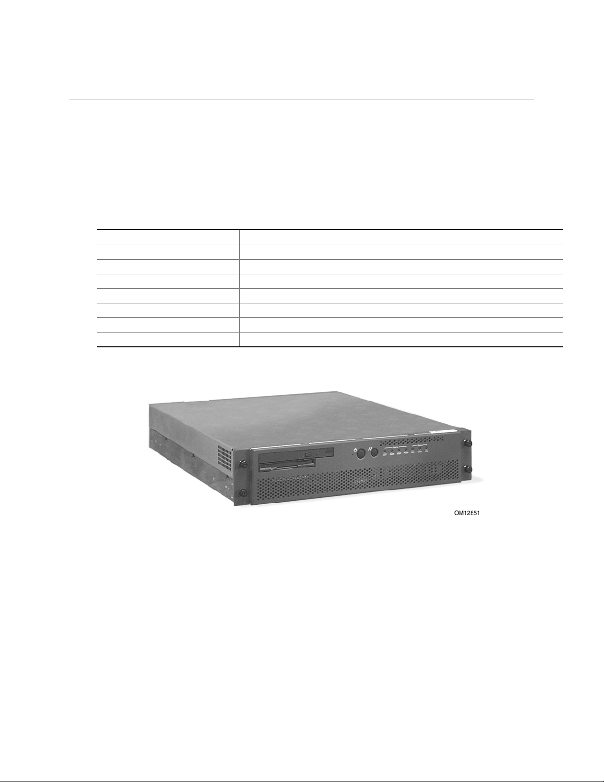
The cc3300 Carrier Grade Server is a rack-mounted server that supports one to two Intel® Pentium®
III processors and up to 6 Gbytes of SDRAM memory. The server supports high availability
features such as hot-swap and redundant power supply modules. The scalable architecture of the
server supports symmetric multiprocessing (SMP).
Physical Specifications
Table 1. Server Physical Specifications
Specification Value
Weight 35 lbs
Height 3.5 inches (89 mm)
Width 17.5 inches (445 mm)
Depth 20 inches (508 mm)
Front clearance 2 inches (76 mm)
Side clearance 1 inches (25 mm)
Rear clearance 3.6 inches (92 mm)
Figure 1. cc3300 Carrier Grade Server Chassis
Chassis Description 13
Page 14

HP cc3300 Carrier Grade Server Product Guide
Environmental Specifications
The cc3300 Carrier Grade Server has been tested to the environmental specifications as indicated in
Table 2. All testing has been performed per procedures defined in Bellcore GR-63-CORE NEBS
Physical Protection, Bellcore GR-3580 NEBS Criteria Levels, Bellcore GR-1089-CORE EMC and
Electrical Safety – Generic Criteria for Network Telecommunications Equipment. .
Table 2. Environmental Specifications Summary
Environment Specification
Temperature operating
Temperature non-operating
Altitude 0 to 1,800 m (0 to 5,905 ft)
Humidity non-operating
Vibration operating Swept sine survey at an acceleration amplitude of 0.1 g from 5 to 100 Hz
Vibration non-operating Swept sine survey at an acceleration amplitude of 0.5 g from 5 to 50 Hz at a
Shock operating Half-sine 2 G, 11 ms pulse, 100 pulses in each direction, on each of the
Shock non-operating Trapezoidal, 25 G, 170-inch/sec delta V, three drops in each direction, on
Electrostatic discharge
(ESD)
Acoustic
10 °C to 35 °C (50° F to 95° F)
-40 °C to 70 °C (-104° F to 158° F)
95%, non-condensing at temperatures of 23° C (73° F) to 40° C (104° F)
and back to 5 Hz at a rate of 0.1 octave/minute, 90 minutes per axis on all
three axes as per Bellcore GR-63-CORE standards.
rate of 0.1 octaves/minute, and an acceleration amplitude of 3.0g from 50 to
500 Hz at a rate of 0.25 octaves/minute, on all three axes as per Bellcore
GR-63-CORE standard.
2.2 Grms, 10 minutes per axis on all three axes.
three axes.
each of the three axes.
Tested to ESD levels up to 15 kilovolts (kV) air discharge and up to
8 kV contact discharge without physical damage.
Sound pressure: < 55 dBA at ambient temperatures < 28°C measured at
bystander positions in operating mode.
Sound power: < 6.5 BA at ambient temperatures < 28°C in operating mode.
Power
Maximum current at 100 VAC 1.8 Amps
Maximum current at 120 VAC 1.5 Amps
Maximum current at 230 VAC 0.8 Amps
Does the input current differ at 50 to 60Hz (if yes, input the highest value) No
Maximum peak inrush current 17.7 Amps
Time to decay to 25% of maximum peak 0.3 Seconds
Time duration to return to nominal 6 Seconds
Total harmonic distortion (voltage) 0.12%
Power factor 0.87
KVA rating 0.19 KVA
Heat dissipation 190 Watts
BTU’s per hour 649 BTU/hr
14 Chassis Description
Page 15

HP cc3300 Carrier Grade Server Product Guide
Kcal per hour 45 Cal/sec
Nominal rated voltages 100 – 240 V
Maximum operating voltage 264 V
Minimum operating voltage 87 V
Rated (marked) line current(s) 4 / 2 Amps
Line voltage power-fail threshold 73 V
Dropout carry-through time at minimum line voltage 20 mSec
Mating AC input receptacle type C-13 C13, etc
Branch circuit breaker size at 100 VAC 15/20 Amps
Branch circuit breaker size at 120 VAC 15/20 Amps
Frequency range non-strappable 47 - 66 Hz
DC input (if applicable) 48 Volts nominal
DC input (if applicable) 4.6 Amps
EMC
Radiated filed immunity – what frequencies are sensitive below 10 v/m None
ESD immunity – Maximum kV with no loss of function 4/8 kV
ESD immunity – Maximum kV with no component damage 4/8 kV
Sound power level (LWA) 6.8 B
Sound pressure level (LPA) at operator position 50.3 dB
Transient spike immunity amplitude 2 Kv
Transient spike immunity duration 50 Micro Sec.
Transient spike immunity rise time 1.2 Micro Sec.
Chassis Description 15
Page 16
HP cc3300 Carrier Grade Server Product Guide
Chassis Feature Location
Front Panel
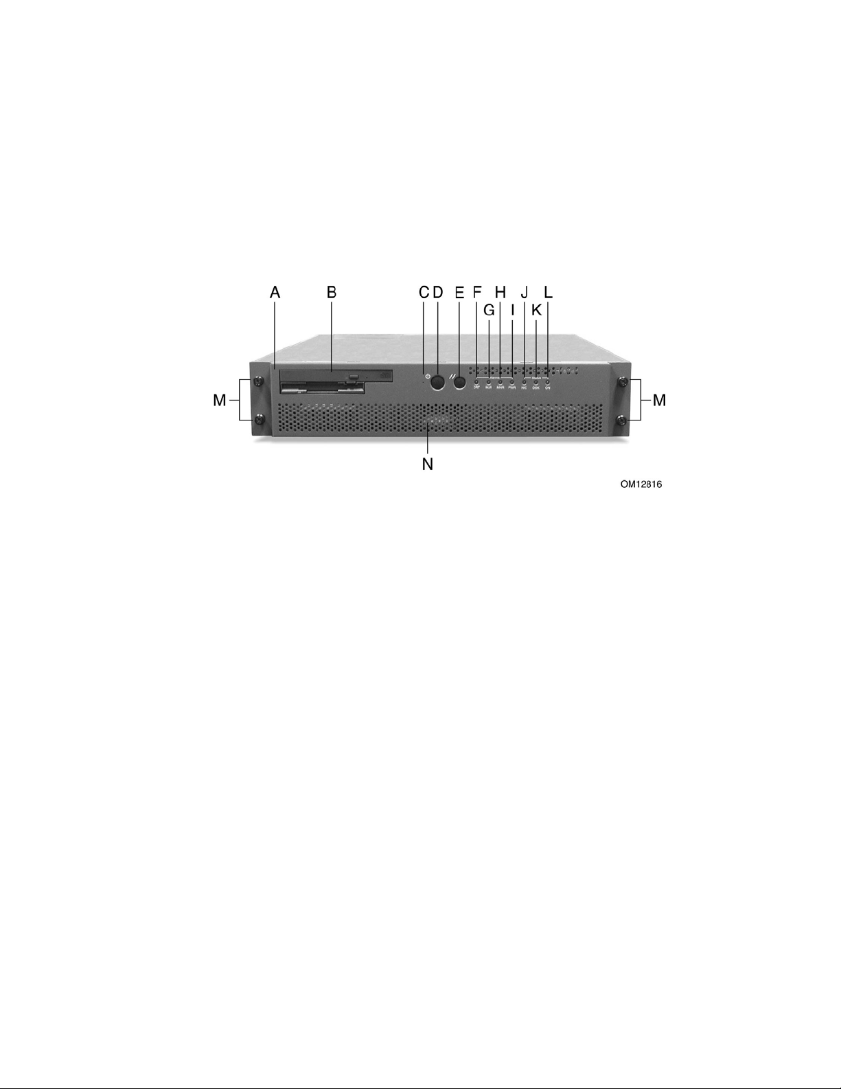
Figure 2 shows the front view of the system including the front panel. The front panel contains
system control switches, alarm indicators and relays, and status indicators. Front panel controls and
LEDs are summarized in Table 3.
A Bezel H Alarm: MNR
B Peripheral Bay I Alarm: PWR
C NMI Switch J Status: NIC
D Power Switch K Status: DSK
E Reset Switch L Status: ON
F Alarm: CRT M Bezel Removal Thumbscrews
G Alarm: MJR N Hard Drive Tray
Figure 2. Front Panel
16 Chassis Description
Page 17

Table 3. Front Panel Features
Item Feature Description
Front Panel Switches
C NMI switch A momentary switch used to instruct the processor to copy system memory to
D Power switch Toggles the system power on/off.
E Reset switch Reboots and initializes the system.
Front Panel Alarm LEDs and Relays
F Critical (amber) When continuously lit, indicates the presence of a Critical System Fault. A
G Major (amber) When continuously lit, indicates the presence of a Major System Fault. A major
H Minor (amber) When conti nuously lit, indicates the presence of a Minor System Fault. A minor
I Power (amber) When continuously lit, indicates the presence of a Power System Fault.
Front Panel Status LEDs
J NIC activity LED
(green)
K HDD activity
LED (green)
L Main power
LED (green)
HP cc3300 Carrier Grade Server Product Guide
the hard drive. Pressing the recessed button with a paper clip or pin puts the
server in a halt state for diagnostic purposes and allows you to issue a
non•maskable interrupt. After issuing the interrupt, a memory dump can be
performed to determine the cause of the problem.
critical system fault is an error or event that is detected by the system with a
fatal impact to the system. In this case, the system cannot continue to operate.
An example could be the loss of a large section of memory. . Additionally, the
front panel critical alarm relay will engage.
system fault is an error or event that is detected by the system that has
discernable impact to system operation. In this case, the system can continue
to operate but in a “degraded” fashion (reduced performance or loss of nonfatal feature reduction). An example could be the loss of one of two mirrored
disks. Additionally, the front panel major alarm relay will engage.
system fault is an error or event that is detected by the system but has little
impact to actual system operation. An example would be a correctable
ECC error. Additionally, the front panel minor alarm relay will engage.
Additionally, the front panel power alarm relay will engage.
Indicates NIC activity.
Indicates any system SCSI hard drive activity.
When continuously lit, indicates the presence of DC power in the server. The
LED goes out when the power is turned off or the power source is disrupted.
When it is blinking green, it indicates that the system is in ACPI sleep mode.
Chassis Description 17
Page 18
HP cc3300 Carrier Grade Server Product Guide
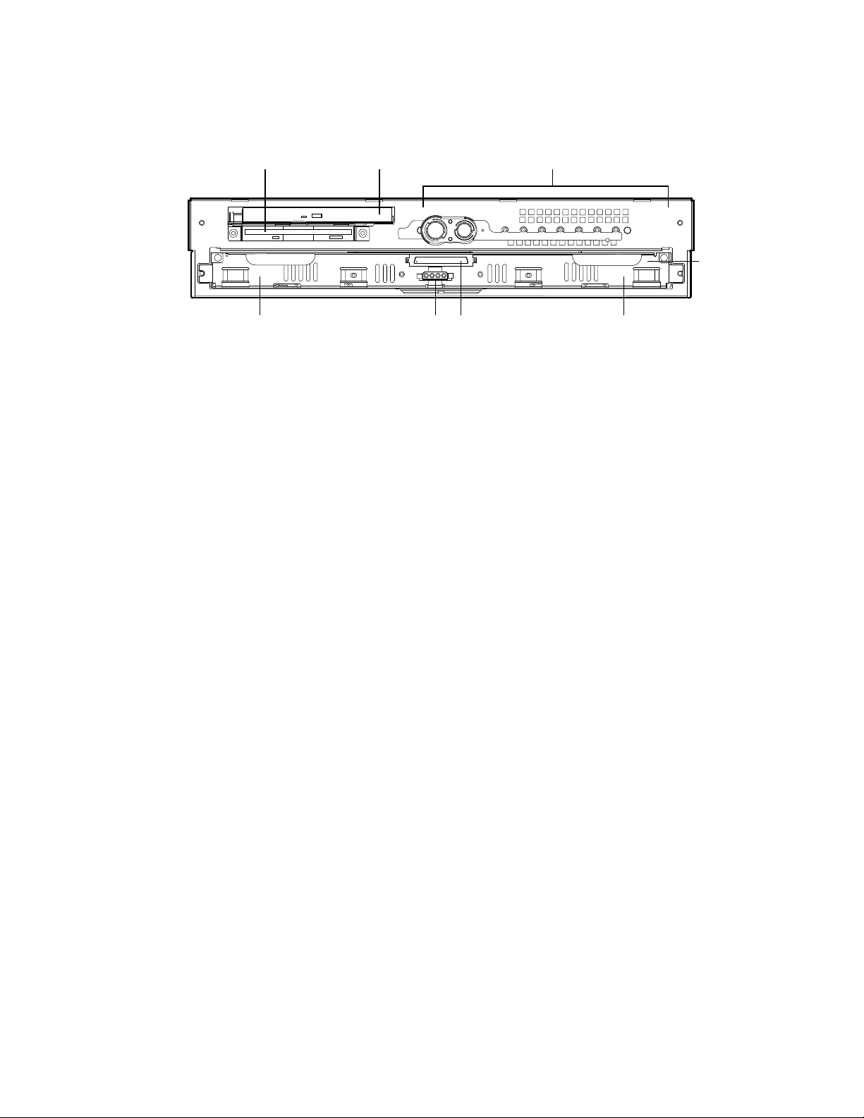
Figure 3 shows the front view of the system with the bezel removed.
A B C
H EFG
A Floppy Drive E Left SCSI Drive Bay
B CD-ROM Drive F Hard Drive Tray Ribbon Cable Connector
C Front Panel Switches and LEDs G Hard Drive Tray Power Connector
D Hard Drive Tray H Right SCSI Drive Bay
Figure 3. Front View with Bezel Removed
OM12817
D
18 Chassis Description
Page 19
Back Panel
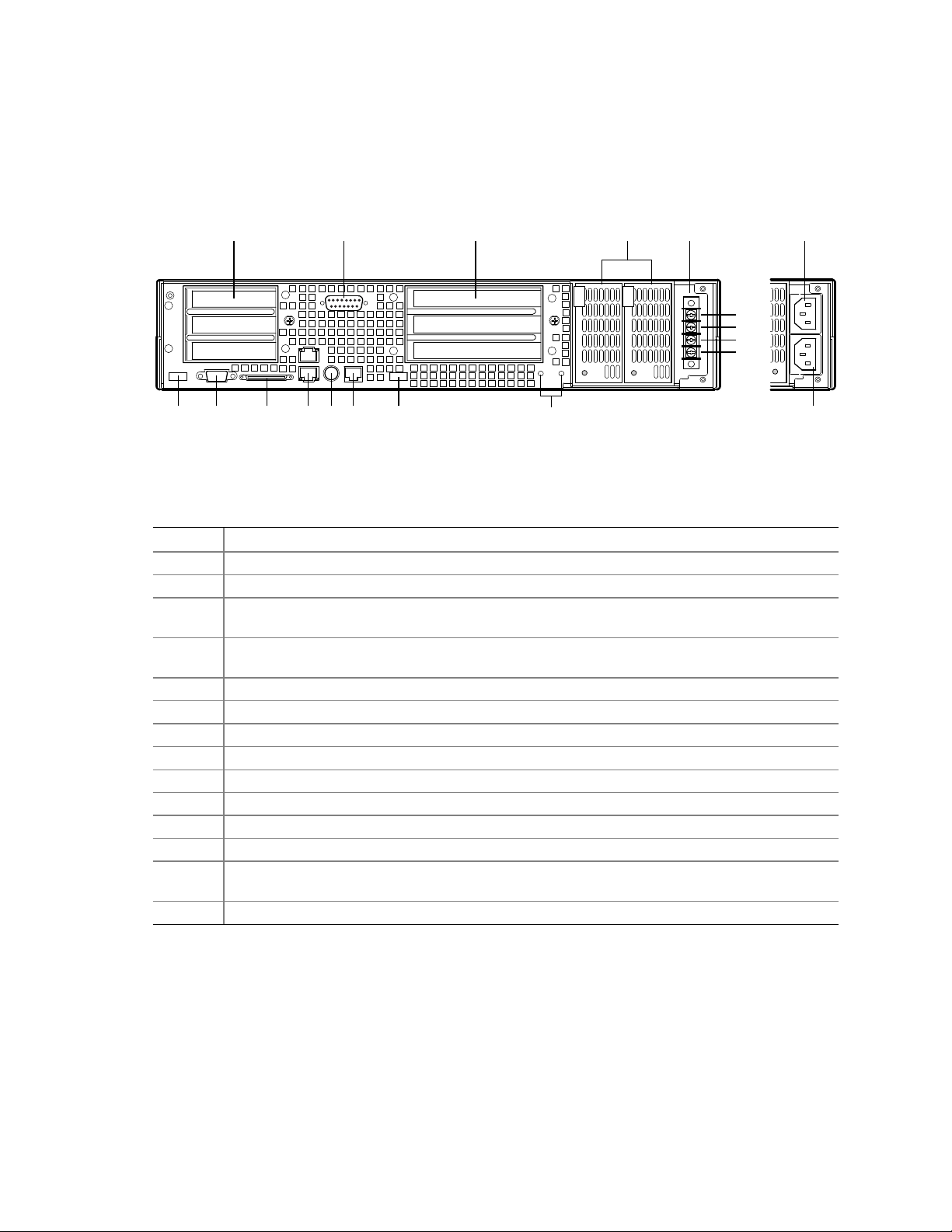
Figure 4 shows the back panel view of the system.
HP cc3300 Carrier Grade Server Product Guide
A C EB D
N
+
-
+
-
F G H I J K L
Figure 4. Back Panel DC Version, AC Version Shown at Right
Table 4. Back Panel Features
Item Description
A Three low profile, half-length 64-bit, 66 MHz PCI add-in board slots (3.3V riser board)
B DB-15 male connector for front panel alarm relay contacts
C Three full height, full length 64-bit, 33 MHz PCI add-in board slots (5 V riser board), or,
Three full height, full length 64-bit, 66 MHz PCI add-in board slots (3.3 V riser board)
D Redundant, hot-plug power supplies (AC and DC power supplies require different power supply
cages)
E Four-terminal DC input power connector for DC input power supply cage
F USB port 1
G Video connector
H External wide SCSI Ultra† 160 68-pin connector
I Dual NIC 10/100 E/N RJ45 connectors NIC 1 (lower) and NIC 2 (upper)
J PS/2†-compatible keyboard port
K Serial port (COM2), 8-pin RJ45 connector
L USB port 0
M Two grounding lugs for attachment of grounding wire to chassis. Use only when configured with
DC input power supply
N and O AC input power connectors for AC input power supply cage (shown in inset)
M
OM12818
O
Chassis Description 19
Page 20
HP cc3300 Carrier Grade Server Product Guide
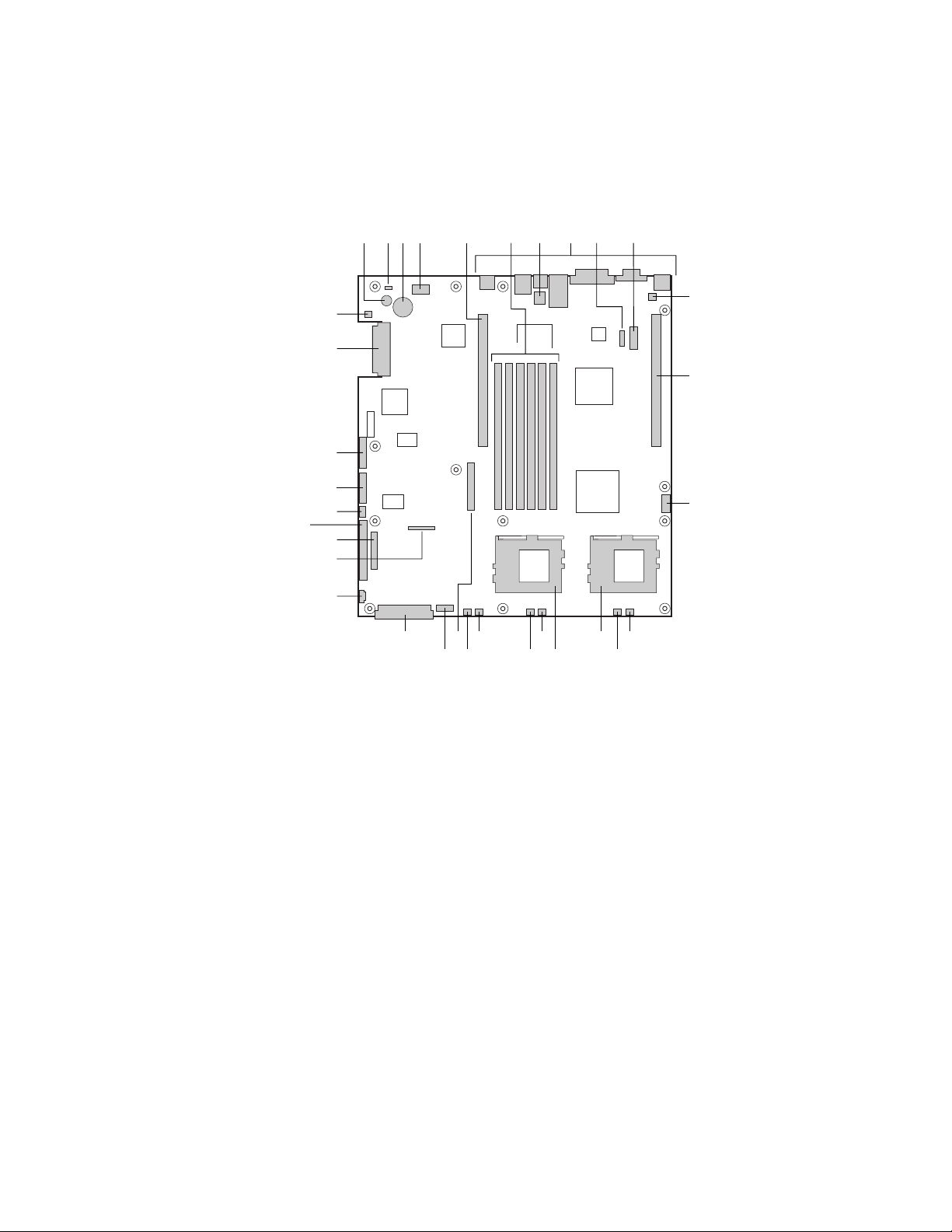
Internal Chassis Features
Figure 5 shows the location of the server board’s connectors and other components.
A C D E
B
GG
FF
EE
DD
CC
BB
AA
Z
Y
TV
UW
A
Speaker R Sys fan 2 connector
B
ID LED S CPU 1 fan connector
C
Battery T Sys fan 1 connector
D
Diagnostic LEDs (POST code) U Aux fan connector
E
66 MHz/64-bit PCI riser slot (full height) V Floppy drive connector
F
DIMM slots W Fan module connector
G
DCD/DSR jumper block X Main power connector
H
I/O ports Y Auxiliary signal connector
I
ICMB connector Z Floppy/FP/IDE connector
J
COM 1 serial header AA Alternate front panel connector
K
Chassis intrusion connector BB ATA/IDE connector
L
66 MHz/64-bit PCI riser slot (low profile) CC IPMB connector
M
USB 3 & 4 header DD SSI front panel connector
N
Sys fan 3 connector EE Configuration jumper block
O
CPU 2 fan connector FF SCSI connector (SCSI version only)
P
Secondary processor socket GG Hard Disk Drive LED header
Q
Primary processor socket
H
G
R
S
JF I
K
L
M
PX N
OQ
OM12815
Figure 5. Server Board Connector and Component Locations
20 Chassis Description
Page 21

HP cc3300 Carrier Grade Server Product Guide
Processor
The server board accommodates one or two Intel Pentium III processors up to 1-26 GHz with
512k cache.
Memory
The system board contains six 168-pin DIMM slots each supporting 72-bit ECC (64-bit main
memory plus ECC) registered SDRAM DIMMs (PC-133 compatible). You may install a minimum
of 256 MB (128MB x 2) and as much as 6 GB.
NOTE
DIMMs supplied with the server have been tested for compatibility with the
cc3300 server. It is recommended that HP tested memory is used when
adding memory capacity to the server.
HP cc3300 Carrier Grade Server Memory Products
Product Number ECC SyncDRAM in module DIMM cards in module Height of DIMMs Server Used With
A6950A 256 MB Two cards (128 MB each) 43.2 mm (1.7") hp carrier grade server cc3300
A6909A 512 MB Two cards (256 MB each) 43.2 mm (1.7") hp carrier grade server cc3300
A6910A 1,024 MB Two cards (512 MB each) 43.2 mm (1.7") hp carrier grade server cc3300
A6916A 2,048 MB Two cards (1,024 MB each) 43.2 mm (1.7") hp carrier grade server cc3300
PCI Riser Slots
The server board has two PCI riser slots, each capable of supporting 64-bit/66-MHz PCI riser cards.
PCI features:
• Bus speed up to 66 MHz
• 32 bit memory addressing
• 5 V/3.3 V signaling environment
• Burst transfers of up to 512 Mbps
• 8, 16, 32, or 64-bit data transfers
• Plug and Play ready
• Parity enabled
Video
The server board uses an ATI RAGE XL PCI graphics accelerator with 8 MB of video SDRAM
that supports all standard IBM
• Pixel resolutions up to 1600 x 1200 under 2D and 1024 x 768 under 3D
• CRT and LCD monitors up to 100 Hz vertical refresh rate
The server board supports disabling of the onboard video through the BIOS setup menu or when a
plug in video card is installed in any of the PCI slots.
†
VGA modes. The embedded SVGA video subsystem supports:
SCSI Controller
The server board includes an embedded Adaptec† AIC-7899W SCSI controller providing dual
Ultra160 Low Voltage Differential (LVD) SCSI channels.
Chassis Description 21
Page 22

HP cc3300 Carrier Grade Server Product Guide
The SCSI bus is terminated on the server board with active terminators that cannot be disabled.
The onboard device must always be at one end of the bus. The device at the other end of the cable
is terminated with the active terminator on the SCSI cable installed in the system.
Network Controller
NOTE
To ensure EMC product regulation compliance for intra-building lighting
surges, the system must only be used with shielded LAN cables that are
grounded at both ends.
®
The server board uses two Intel
10Base-T/100Base-TX network subsystems.
On the server board, NIC 1 can be used as both a network interface and server management
interface.
NIC Connector and Status LEDs
The 82550 controller drives LEDs on the network interface connector that indicate link/activity on
the LAN and 10- or 100-Mbps operation. The green LED indicates network connection when on
and TX/RX activity when blinking. The yellow LED indicates 100-Mbps operation when lit.
82550PM Fast Ethernet Controllers and supports two
Network Teaming Features
NOTE
Using both on-board NICs in a team does not allow the use of NIC 1 for
server management access. To support both network teaming features and
server management features, a third NIC must be added and teamed to NIC 2.
The network controller provides several options for increasing throughput and fault tolerance when
†
running Linux
• Adapter Fault Tolerance (AFT) - provides automatic redundancy for your adapter. If the
primary adapter fails, the secondary takes over. AFT works with any hub or switch.
• Adaptive Load Balancing (ALB) - creates a team of 2 - 6 adapters to increase transmission
throughput. Also includes AFT. Works with any 10Base-TX or 100Base-TX switch.
• Fast EtherChannel
increase transmission and reception throughput. Also includes AFT. Requires a FEC-enabled
switch.
To set up an option, read the instructions in the Linux readme files.
Adapter Fault Tolerance
Adapter Fault Tolerance (AFT) is a simple, effective, and fail-safe approach to increase the
reliability of server connections. AFT gives you the ability to set up link recovery to the server
adapter in case of a cable, port, or network interface card failure. By assigning two server adapters
as a team, AFT enables you to maintain uninterrupted network performance.
:
†
(FEC) or Intel® Link Aggregation - creates a team of up to 6 adapters to
AFT is implemented with two server adapters: a primary adapter and a backup, or secondary,
adapter. During normal operation, the backup will have transmit disabled. If the link to the
primary adapter fails, the link to the backup adapter automatically takes over.
22 Chassis Description
Page 23

HP cc3300 Carrier Grade Server Product Guide
Preferred Primary Adapter
With multiple adapters installed, you can specify one as the Preferred Primary adapter. For
example if you have a server with a Gigabit LAN as the primary adapter and a 10/100 Base TX
LAN adapter as the secondary, you could configure the Gigabit LAN server adapter to be the
preferred primary. In this scenario, if the Gigabit LAN server adapter fails, the 10/100 Base TX
will take over. Then when the Gigabit LAN server adapter is replaced, it will automatically revert
to being the primary adapter in the team.
If a Preferred Primary is not selected, PROSet will attempt to select the best adapter, based on
adapter model and speed.
Mixed Adapter Teaming
AFT supports up to six server adapters per team, in any mix.
Adaptive Load Balancing
Adaptive Load Balancing (ALB) is a simple and efficient way to increase your server's transmit
throughput. With ALB you group server adapters in teams to provide an increased transmit rate
(up to 8 Gbps) using a maximum of eight adapters. The ALB software continuously analyzes
transmit loading on each adapter and balances the rate across the adapters as needed. Adapter
teams configured for ALB also provide the benefits of AFT. Receive rates remain at 100 Mbps or
1 Gbps depending on the primary adapter’s capability.
To use ALB, you must have 2-6 server adapters installed in your server or workstation and linked
to the same network switch.
Keyboard and Mouse
The keyboard controller is PS/2-compatible. If specified through the System Setup Utility (SSU),
the server may be locked automatically if there is no keyboard or mouse activity for a predefined
length of time. Once the inactivity (lockout) timer has expired, the keyboard and mouse do not
respond until the previously stored password is entered.
Chassis Description 23
Page 24

HP cc3300 Carrier Grade Server Product Guide
RJ-45 Serial Port
The rear RJ-45 serial port is a fully functional COM port that supports any standard serial device
and provides support for serial concentrators, which typically support RJ45 serial connectors. For
server applications that use a serial concentrator to access the server management features of the
baseboard, a standard 8-pin CAT-5 cable from the serial concentrator is plugged directly into the
rear RJ45 serial port. The 8 pins of the RJ45 connector can be configured to match either of two
pin-out standards used by serial port concentrators. To accommodate either standard, the
J6A2 jumper block located directly behind the rear RJ45 serial port must be jumpered appropriately
according to which standard is desired.
NOTE
The RJ45 serial port’s default configuration is DSR. For serial concentrators
requiring a DCD signal, configure the jumper block as shown in Figure 37.
For those server applications requiring a DB9 serial connector, use an 8-pin RJ45-to-DB9 adapter
(A6900-6303). Table 5 defines the pin-out required for the adapter to provide RS232 support.
Table 5. Rear COM2 Port Adapter Pin-out
RJ45 Signal Abbreviation DB9
1 Request to Send RTS 7
2 Data Terminal Ready DTR 4
3 Transmitted Data TD 3
4 Signal Ground SGND 5
5 Ring Indicator RI 9
6 Received Data RD 2
7 DCD or DSR DCD/DSR 1 or 6
8 Clear To Send CTS 8
NOTE
The RJ45-to-DB9 adapter should match the configuration of the serial device
used. One of two pin-out configurations are used depending on whether the
serial device requires a DSR or DCD signal. The final adapter configuration
should also match the desired pin-out of the RJ45 connector, as it can also be
configured to support either DSR or DCD.
24 Chassis Description
Page 25

HP cc3300 Carrier Grade Server Product Guide
ACPI
The SERVER BOARD supports the Advanced Configuration and Power Interface (ACPI) as
defined by the ACPI 1.0 and PC97 specifications. An ACPI aware operating system can put the
system into a state where the hard drives spin down, the system fans stop, and all processing is
halted. However, the power supply will still be on and the processors will still be dissipating some
power, so the power supply fans will still run.
The SERVER BOARD supports sleep states s0, s1, s4, and s5:
• s0: Normal running state.
• s1: Processor sleep state. No context will be lost in this state and the processor caches will
maintain coherency.
• s4: Hibernate or Save to Disk: The memory and machine state are saved to disk. Pressing the
power button or other wakeup event will restore the system state from the disk and resume
normal operation. This assumes that no hardware changes have been made to the system while
it was off.
• s5: Soft off: Only the RTC section of the CSB and the BMC are running in this state. No
context is saved by the OS or hardware.
CAUTION
The system is off only when the AC power cord is disconnected.
Security
Software Locks
The BIOS Setup and the System Setup Utility (SSU) provide a number of security features to
prevent unauthorized or accidental access to the system. Once the security measures are enabled,
you can access the system only after you enter the correct password(s). For example:
• Enable the keyboard lockout timer so that the server requires a password to reactivate the
keyboard and mouse after a specified time out period1 to 120 minutes.
• Set and enable a supervisor password.
• Set and enable a user password.
• Set secure mode to prevent keyboard or mouse input and to prevent use of the front panel reset
and power switches.
• Activate a hot key combination to enter secure mode quickly.
• Disable writing to the diskette drive when secure mode is set.
• Disable access to the boot sector of the operating system hard disk drive.
Using Passwords
You can set the user password, the supervisor password, or both passwords.
If only the user password is set, you:
• Must enter the user password to enter BIOS Setup or the SSU.
• Must enter the user password to boot the server if Password on Boot is enabled in either the
BIOS Setup or SSU.
• Must enter the user password to exit secure mode. If only the supervisor password is set, you:
• Must enter the supervisor password to enter BIOS Setup or the SSU.
Chassis Description 25
Page 26

HP cc3300 Carrier Grade Server Product Guide
• Must enter the supervisor password to boot the server if Password on Boot is enabled in
either the BIOS Setup or SSU.
• Must enter the supervisor password to exit secure mode.
If both passwords are set, you:
• May enter the user password to enter BIOS Setup or the SSU. However, you will not be able to
change many of the options.
• Must enter the supervisor password if you want to enter BIOS Setup or the SSU and have
access to all of the options.
• May enter either password to boot the server if Password on Boot is enabled in either the BIOS
Setup or SSU.
• May enter either password to exit secure mode.
Secure Mode
Configure and enable the secure boot mode by using the SSU. When secure mode is in effect:
• You can boot the server and the operating system will run, but you must enter the user
password to use the keyboard or mouse.
• You cannot turn off system power or reset the server from the front panel switches.
• Secure mode has no effect on functions enabled via remote server management or power
control via the watchdog timer.
Taking the server out of secure mode does not change the state of system power. That is, if you
press and release the power switch while secure mode is in effect, the system will not be powered
off when secure mode is later removed. However, if the front panel power switch remains
depressed when secure mode is removed, the server will be powered off.
26 Chassis Description
Page 27

HP cc3300 Carrier Grade Server Product Guide
Summary of Software Security Features
Table 6 lists the software security features and describes what protection each offers. In general, to
enable or set the features listed here, you must run the SSU and go to the Security Subsystem
Group, menu. The table also refers to other SSU menus and to the Setup utility.
Table 6. Software Security Features
Feature Description
Secure mode How to enter secure mode:
Setting and enabling passwords automatically places the system in secure mode.
If you set a hot-key combination (through Setup), you can secure the system
simply by pressing the key combination. This means you do not have to wait for
the inactivity time-out period.
When the system is in secure mode:
The server can boot and run the operating system, but mouse and keyboard input
is not accepted until the user password is entered.
At boot time, if a CD is detected in the CD-ROM drive or a diskette in drive A, the
system prompts for a password. When the password is entered, the server boots
from CD or diskette and disables the secure mode.
If there is no CD in the CD-ROM drive or diskette in drive A, the server boots from
drive C and automatically goes into secure mode. All enabled secure mode
features go into effect at boot time.
To leave secure mode: Enter the correct password(s).
Disable writing to
diskette
In secure mode, the server will not boot from or write to a diskette unless a
password is entered.
To write protect access to diskette whether the server is in secure mode or not, use
the Setup main menu, Floppy Options, and specify Floppy Access as read only.
Continued
Chassis Description 27
Page 28

HP cc3300 Carrier Grade Server Product Guide
Table 6. Software Security Features (continued)
Feature Description
Set a time out period
so that keyboard and
mouse input are not
accepted
Also, screen can be
blanked, and writes to
diskette can be
inhibited
Control access to
using the SSU: set
supervisor password
Control access to the
system other than
SSU: set user
password
Boot without
keyboard
Specify the boot
sequence
Specify and enable an inactivity time out period of from 1 to 120 minutes.
If no keyboard or mouse action occurs for the specified period, attempted keyboard
and mouse input will not be accepted.
The monitor display will go blank, and the diskette drive will be write protected
(if these security features are enabled through Setup).
To resume activity: Enter the correct password(s).
To control access to setting or changing the system configuration, set a supervisor
password and enable it through Setup.
If both the supervisor and user passwords are enabled, either can be used to boot
the server or enable the keyboard and/or mouse, but only the supervisor password
will allow Setup to be changed.
To disable a password, change it to a blank entry or press CTRL-D in the Change
Password menu of the Supervisor Password Option menu found in the Security
Subsystem Group.
To clear the password if you cannot access Setup, change the Clear Password
jumper (see Chapter 5).
To control access to using the system, set a user password and enable it through
Setup.
To disable a password, change it to a blank entry or press CTRL-D in the Change
Password menu of the User Password Option menu found in the Security
Subsystem Group.
To clear the password if you cannot access Setup, change the Clear Password
jumper (see Chapter 5).
The system can boot with or without a keyboard. During POST, before the system
completes the boot sequence, the BIOS automatically detects and tests the
keyboard if it is present and displays a message.
The sequence that you specify in setup will determine the boot order. If secure
mode is enabled (a user password is set), then you will be prompted for a
password before the server fully boots. If secure mode is enabled and the “Secure
Boot Mode” option is also enabled, the server will fully boot but will require a
password before accepting any keyboard or mouse input.
28 Chassis Description
Page 29
HP cc3300 Carrier Grade Server Product Guide
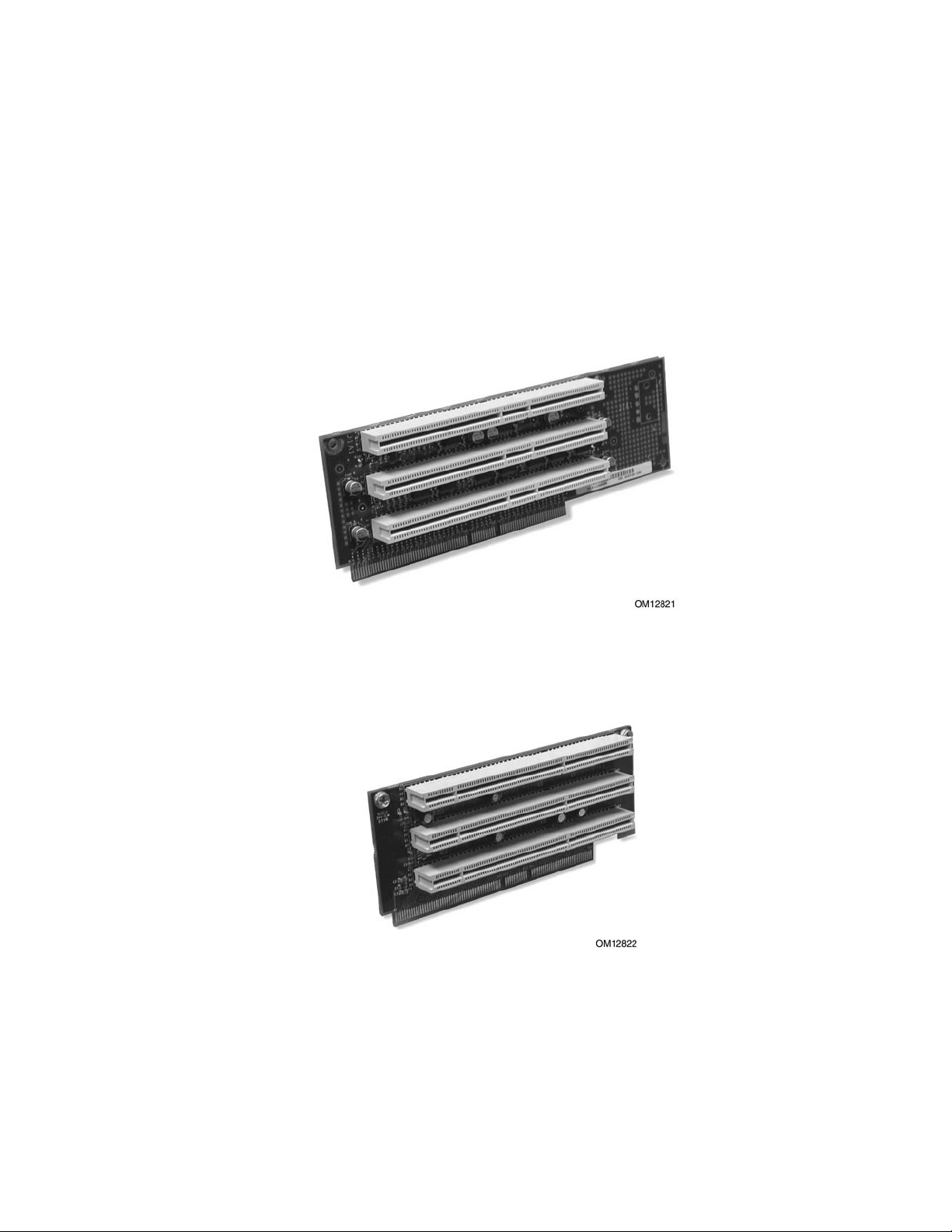
PCI I/O Riser Cards
The server can support two riser cards, a 5 Volt full height riser card, and a 3.3 Volt half-height
riser card or two 3.3 volt half-height riser cards. Features of the 5 Volt riser card include:
• Support for three 33 MHz 5 Volt 64-bit PCI add-in cards
• Provides 5 Volt to 3.3 Volt signal level translation
The 5 Volt riser card contains voltage level translation, converting the 5 Volt PCI add-in card
signals to conform to the server board, which has 3.3 Volt signaling levels. The card supports up to
50 W total with a limit of 25 Watts per slot. Figure 6 illustrates the 5 Volt riser card.
Figure 6. 5 Volt Riser Card
The 3.3 Volt riser card supports three 3.3 Volt 64-bit slots at 66 MHz. The card supports up to 30
W total power consumption. Figure 7 illustrates the 3.3 Volt riser card.
Figure 7. 3.3 Volt Riser Card
Chassis Description 29
Page 30

HP cc3300 Carrier Grade Server Product Guide
A 3.3v PCI riser card is installed in the server as a part of the standard configuration. Optional PCI
riser cards are also available. Refer to the following table for riser card details.
Table 7. HP cc3300 Carrier Grade Server PCI I/O Riser Card Details
Supported Card Dimensions Product
Number
standard
configuration
A6928A (3.3
volt Riser Card)
A6929A (5 volt
Riser Card
Number of PCI I/O
Slots
3 3.3 volt 64/66, 64/33,
3 3.3 volt 64/66, 64/33,
3 5.0 volt 64/33, 32/33 Yes Yes No Yes
Voltage Operation
(bits / MHz)
32/66, 32/33
32/66, 32/33
Full Length Half Length Low Profile Full Height
No Yes Yes No
Yes Yes No Yes
PCI I/O Cards
The following PCI cards are available for the cc3300 Carrier Grade Server.
I/O Card
Ultra 160 SCSI interface, low profile A6919A Universal Half length Low profile VHDCI
Ultra 160 SCSI interface, full height A6919A opt.001 Universal Half length Full height VHDCI
10/100BaseTX LAN Adapter, low profile A6920A Universal Half length Low profile RJ45 Yes 2
10/100BaseTX LAN Adapter, full height A6920A opt.001 Universal Half length Full height RJ45 Yes 2
Gigabit LAN Adapter over copper A6921A Universal Half Length Low Profile RJ45 Yes 2
Gigabit LAN Adapter over copper, full
height
Product
Number
A6921A opt 001 Universal Half length Full Heighte RJ45 Yes 2
3.3 volt,
5.0 volt, or
Universal
Full or Half
Length
Low Profile or
Full Height
Connector
Types
(VHDTS68)
(VHDTS68)
Factory
Integrate
Max Cards
Per hp
cc3300
Yes 2
Yes 2
Power Supplies
The power supply cage shown in Figure 8 is accessed from the rear of the chassis. The power
supply cage supports up to two hot-swap 350 W power supplies (either AC input or DC input) in a
(1 + 1) redundant configuration. A power supply filler module (shown at left in Figure 8) for the
empty power supply site is supplied for systems without redundancy.
Only the DC input version is NEBS certified.
30 Chassis Description
Page 31

HP cc3300 Carrier Grade Server Product Guide
OM13104
Figure 8. Non-redundant AC-Power Supply Subsystem (Filler Module shown at Left)
DC Power Subsystem
This section defines the features of the DC input switching power subsystem.
Features
• 350 W output capability in full DC input voltage range
• “Power Good” indication LEDs
• Predictive failure warning
• Internal cooling fans with multi-speed capability
• Remote sense of 3.3 Volt, 5 Volt, and 12 Volt DC outputs
• “DC_OK” circuitry for brown out protection and recovery
• Built-in load sharing capability
• Built-in overloading protection capability
• Onboard field replaceable unit (FRU) information
2
• I
C interface for server management functions
• Integral handle for insertion/extraction
Introduction
The DC version of the cc3300 Carrier Grade Server uses a -48 to -60 VDC input switching power
subsystem, which provides up to 350 Watts with -48 to -60 VDC input and with current and remote
sense regulation. The power subsystem consists of one or two 350-Watt power supply modules. A
system with two modules forms a redundant, hot-swappable (1+1) power subsystem.
Interface Requirements
DC Input
The DC power source may produce hazardous voltage levels exceeding -60 VDC and high energy
levels above 240VA that may cause electric shock or burns. All DC input connections should be
Chassis Description 31
Page 32

HP cc3300 Carrier Grade Server Product Guide
made only by a qualified service person only to prevent injury. All wiring terminals connected to
the DC input terminal block must be fully insulated with no exposed bare metal.
DC Output Connectors
The power subsystem DC power and control signals are interfaced to the server system via wire
harnesses when the power supply modules are inserted into the power subsystem enclosure. The
safety ground pin of the power supply module is the first pin to connect and the last to disconnect
when the module is being inserted or removed from the power subsystem housing. In addition to
the 5 V Standby, -12 V, +3.3 V, +5 V and +12 V DC outputs, the following signals and output pins
are included:
• +3.3 VDC remote sense
• +5 VDC remote sense
• +12 VDC remote sense
• Remote sense return
• Power Subsystem On (DC PWR enable)
• Power Good
2
• I
C*
*
PS Failure, PS Presence, PS Predictive Fail, +12 V Mon, +5 V Mon, and the 5 V Standby rails
failure are being monitored via an I
2
C interface chip.
Power Supply Module LED Indicators
There is a single bi-color LED to indicate power supply status visible on the back of the system.
Table 8 shows the conditions confirmed by the LED indicators.
Table 8. LED Indicators
Power Supply Condition Power Supply LED
No DC power to all PSU OFF
No DC power to this PSU only AMBER
DC present / Only Standby Outputs On BLINK GREEN
Power supply DC outputs ON and OK GREEN
Power Supply in Alert Condition BLINK AMBER
Power supply failure (OTP, OCP, OVP, UV) AMBER
DC Input Voltage Specification
The power supply will operate within all specified limits over the following input voltage range.
The power supply will power-off if the DC input is less than -34 VDC.
Table 9. DC Input Rating
Parameter
Voltage -38VDC -48 to -60VDC -75VDC 13.5 Amps
1
Maximum input current is measured at the lowest input voltage that the power supply continues to operate. This is not to
be used for determining agency input current markings.
Minimum
Tolerance
Nominal
Rating
Maximum
Tolerance
1
Maximum Input
Current
32 Chassis Description
Page 33

HP cc3300 Carrier Grade Server Product Guide
DC Output Current Specifications
The combined output power of all outputs will not exceed 350 W. Each output has a maximum and
minimum current rating shown in Table 10. The power supply meets both static and dynamic
voltage regulation requirements for the minimum dynamic loading conditions. The power supply
meets only the static load voltage regulation requirements for the minimum static load conditions.
Table 10. 350W Load Ratings
+3.3V +5V +12V -12V 5VSB
PEAK (10sec) 30A
MAX 20A 20A 25A 0.5A 1.5A
MIN DYNAMIC 2.0A 2.0A 1.5A 0A 0A
MIN STATIC 1A 1A 0A 0A 0A
Note: The maximum combined power of the 3.3 V and 5 V outputs is 150 W.
AC Power Subsystem
This section defines the AC-input switching power subsystem.
Features
• 350 W output capability in full DC input voltage range
• “Power Good” indication LEDs
• Predictive failure warning
• Internal cooling fans with multi-speed capability
• Remote sense of 3.3 V, 5 V, and 12 VDC outputs
• AC_OK circuitry for brown out protection and recovery
• Built-in load sharing capability
• Built-in overloading protection capability
• Onboard field replaceable unit (FRU) information
2
• I
C interface for server management functions
• Integral handle for insertion/extraction
Introduction
The AC version of the cc3300 Carrier Grade server uses a -48 to -60 VDC input switching power
subsystem, which provides up to 350 Watts with -48 to -60 VDC input and with current and remote
sense regulation. The power subsystem consists of one or two 350-Watt power supply modules. A
system with two modules forms a redundant, hot-swappable (1+1) power subsystem. There is a
single bi-color LED to indicate power supply status. Refer to Table 11 for conditions of the power
supply LEDs.
Table 11. LED Indicators
Power Supply Condition Power Supply LED
No AC power to all PSU OFF
No AC power to this PSU only AMBER
DC present / Only Standby Outputs On BLINK GREEN
Power supply DC outputs ON and OK GREEN
Chassis Description 33
Page 34

HP cc3300 Carrier Grade Server Product Guide
Power Supply in Alert Condition BLINK AMBER
Power supply failure (OTP, OCP, OVP, UV) AMBER
AC Input Voltage Specification
The power supply operates within all specified limits over the following input voltage ranges.
Harmonic distortion of up to 10% THD will not cause the power supply to exceed specified limits.
Table 12. AC Input Rating
Parameter MIN RATED MAX Max Input Current (350W Version)
Voltage (110) 90 V
Voltage (220) 180 V
Frequency 47 Hz 63 Hz
100-127 V
rms
200-240 V
rms
140 V
rms
264 V
rms
6.7 A
rms
rms
rms
DC Output Current Specifications
The combined output power of all outputs should not exceed 350 W. Each output has a maximum
and minimum current rating shown in Table 13. The power supply meets both static and dynamic
voltage regulation requirements for the minimum dynamic loading conditions. The power supply
meets only the static load voltage regulation requirements for the minimum static load conditions.
Table 13. 350W Load Ratings
+3.3V +5V +12V -12V 5VSB
PEAK (10sec) 30A
MAX 20A 20A 25A 0.5A 1.5A
MIN DYNAMIC 2.0A 2.0A 1.5A 0
MIN STATIC 1A 1A 0A 0A 0A
A
0A
NOTE
The maximum combined power of the 3.3 V and 5 V outputs is 150 W.
Peripheral Bay
The peripheral bay consists of the following two removable media devices. Both devices are
replaced as one assembly.
• ½” Floppy drive
• ½” CD-ROM drive
Hard Drive Tray
The HP cc3300 Carrier Grade Server supports up to two internal disk drives. These disks may be of
different capacities and rotational speeds. An Ultra 160 SCSI controller contained on the system board as
part of core I/O provides the disk drives with an independent SCSI channel. This Ultra 160 SCSI controller
channel is independent of the Ultra 160 SCSI controller channel in core I/O that provides the external Ultra
160 SCSI port.
34 Chassis Description
Page 35

HP cc3300 Carrier Grade Server Product Guide
Cc3300 Internal Disk Drive Product Numbers
Product Number Disk Capacity Rotational speed Disk Replacement Part Number
A6917A 18 GB 10,000 RPM A6917-69001
A6942A 18 GB 15,000 RPM A6942-69001
A6918A 36GB 10,000 RPM A6918-69001
A6943A 36 GB 15,000 RPM A6943-69001
Cooling Subsystem
The cooling subsystem contains a fan array consisting of two 80 x 38 mm fans and two 40 x 28 mm
fans to cool the server board and other components as shown in Figure 9. A fan failure is indicated
by one of the fault LEDs located on the front panel.
OM12820
Figure 9. Fan Array with Four System Fans Installed
Air flows through the bezel, over the peripheral bay and the hard drive tray, passes through the
fans, over the server board, and exhausts through the rear of the chassis.
Each fan provides a tachometer signal output to the server board to indicate a fan failure.
Ambient Temperature Control
The server board contains a pulse-width-modulation (PWM) circuit, that cycles the 12 VDC fan
voltage to provide quiet operation when system baseboard temperature is low, and there are no fan
failures. Under normal baseboard temperature conditions (less than 45 °C), the fan power circuit
supplies an effective fan voltage of 7.0 VDC. When the baseboard temperature exceeds 45 °C, the
fan control circuit ceases cycling and delivers 12 VDC. Following a baseboard temperature
excursion above 45 °C the fan voltage does not reenter PWM mode until the baseboard temperature
drops below 45 °C and all fans are operational.
The cooling subsystem’ design meets acoustic and thermal requirements at the lower fan speed
settings. At the higher fan speed settings, thermal requirements are met for the maximum ambient
temperatures but acoustic requirements may be exceeded.
Chassis Description 35
Page 36

HP cc3300 Carrier Grade Server Product Guide
Server Management Summary
The server board’s server management architecture features a board management controller (BMC),
which autonomously monitors server status and provides the interface to server management
control functions. The BMC is responsible for controlling system power, resets, monitoring
voltages, temperatures, fans, and communicating with secondary controllers on its Intelligent
Platform Management Bus (IPMB).
Detailed server management tool information and supported operating system information is
contained in the Intel Server Control Installation (ISC) Guide For the cc2300 & cc3300 Carrier
Grade Server. ISC is a server management tool that provides real time monitoring and alerting for
server hardware, emergency remote management and remote server setup.
The functions of each controller are summarized in the following sections.
Server Board Management Controller
The BMC on the server board provides server management monitoring capabilities. Associated
with the BMC is a flash memory that holds the operational code, sensor data records (SDR), and
system event log (SEL). A serial EEPROM holds the BMC configuration defaults and field
replaceable unit (FRU) information. The BMC supports the following:
• Server board voltage monitoring
• Fan failure detection
• Fan speed control
• Processor voltage monitoring
• Processor presence detection
• Processor internal error (IERR) monitoring
• Fault resilient booting (FRB)
• Processor disable control
• Watchdog timer
• Periodic system management interrupt (SMI) timer
2
• I
C master controller for the Intelligent Platform Management Bus (IPMB)
• Three private I
• Server management software (SMS) and server management mode (SMM) IPMB message
receiver
• Event message receiver
• System event log (SEL) management and access
• Sensor data record (SDR) repository management and access
• Processor nonmaskable interrupt (NMI) monitoring
• Processor SMI monitoring
• Time-stamp clock
• Secure mode, video blank, and floppy write protect
• Software front panel NMI generation
2
C management bus interfaces
36 Chassis Description
Page 37

2 Regulatory Specifications and Disclaimers
Declaration of the Manufacturer or Importer
We hereby certify that this product is in compliance with European Union EMC Directive
89/336/EEC, using standards EN55022 (Class A) and EN55024 and Low Voltage Directive
73/23/EEC, Standard EN60950.
Safety Compliance
USA: UL 1950 – 3rd Edition/CSA 22.2. No. 950-M93
Canada: UL Certified – 3rd Edition/CSA 22.2. No. 950-M93 for Canada (product bears
the single UL mark for U.S. and Canada)
Europe: Low Voltage Directive, 73/23/EECTUV/GS to EN60950 2nd Edition with
Amendments, A1 = A2 + A3 + A4
International: TUV/CB to IEC 60950 3rd Edition, EN60 950 2nd Edition + Amd 1-4, EMKO-TSE
(74-SEC) 207/94 plus international deviations
Australian / New Zealand: CB Report to IEC 60950, 3rd Edition plus Australian deviations
Electromagnetic Compatibility (EMC)
USA: FCC CFR 47 Part 2 and 15, Verified Class A Limit
Canada: IC ICES-003 Class A Limit
Europe: EMC Directive, 89/336/EEC
• EN55022, Class A Limit, Radiated & Conducted Emissions
• EN55024, ITE Specific Immunity Standard
• EN61000-4-2, ESD Immunity (Level 2 Contact Discharge, Level 3 Air Discharge)
• EN61000-4-3, Radiated Immunity (Level 2)
• EN61000-4-4, Electrical Fast Transient (Level 2)
• EN61000-4-5, AC Surge
• EN61000-4-6, Conducted RF
• EN61000-4-8, Power Frequency Magnetic Fields
• EN61000-4-11, Voltage Dips and Interrupts
• EN61000-3-2, Limit for Harmonic Current Emissions
• EN61000-3-3, Voltage Flicker
Japan: VCCI Class A ITE (CISPR 22, Class A Limit) IEC 1000-3-2 Limit for Harmonic
Current Emissions
Australia/New Zealand: AS/NZS 3548, Class A
Taiwan: BSMI Approval, Class A
Korea: RRL Approval, Class A
Russia: GOST Approved
International: CISPR 22, Class A Limit
Regulatory Specifications and Disclaimers 37
Page 38

HP cc3300 Carrier Grade Server Product Guide
FCC Electromagnetic Compatibility Notice (USA)
This equipment has been tested and found to comply with the limits for a Class A digital device,
pursuant to Part 15 of the FCC Rules. These limits are designed to provide reasonable protection
against harmful interference when the equipment is operating in a commercial environment. This
equipment generates, uses, and can radiate radio frequency energy and, if not installed and used in
accordance with the instructions, may cause harmful interference to radio communications.
Operation of this equipment in a residential area is likely to cause harmful interference. In this
case, the user is required to correct the interference at their own expense. If this equipment does
cause harmful interference to radio or television reception, which can be determined by turning the
equipment off and on; the user is encouraged to try to correct the interference by one or more of the
following measures:
• Reorient or relocate the receiving antenna.
• Increase the separation between the equipment and the receiver.
• Connect the equipment into an outlet on a circuit different from that to which the receiver is
connected.
• Consult the dealer or an experienced radio/TV technician for help.
Any changes or modifications not expressly approved by the grantee of this device could void the
user’s authority to operate the equipment.
The customer is responsible for ensuring compliance of
the modified product.
38 Regulatory Specifications and Disclaimers
Page 39

HP cc3300 Carrier Grade Server Product Guide
Regulatory Specifications and Disclaimers 39
Page 40

HP cc3300 Carrier Grade Server Product Guide
Electromagnetic Compatibility Notices (International)
Europe (CE Declaration of Conformity)
This product has been tested in accordance too, and complies with the Low Voltage Directive
(73/23/EEC) and EMC Directive (89/336/EEC). The product has been marked with the CE Mark to
illustrate its compliance.
Japan EMC Compatibility
English translation of the notice above:
This is a Class A product based on the standard of the Voluntary Control Council for Interference
by Information Technology Equipment (VCCI). If this equipment is used in a domestic
environment, radio disturbance may arise. When such trouble occurs, the user may be required to
take corrective actions.
ICES-003 (Canada)
Cet appareil numérique respecte les limites bruits radioélectriques applicables aux appareils
numériques de Classe A prescrites dans la norme sur le matériel brouilleur: “Appareils
Numériques”, NMB-003 édictée par le Ministre Canadian des Communications.
English translation of the notice above:
This digital apparatus does not exceed the Class A limits for radio noise emissions from digital
apparatus set out in the interference-causing equipment standard entitled “Digital Apparatus,”
ICES-003 of the Canadian Department of Communications.
BSMI (Taiwan)
The BSMI Certification number and the following warning is located on the product safety label
which is located visibly on the external chassis.
40 Regulatory Specifications and Disclaimers
Page 41

HP cc3300 Carrier Grade Server Product Guide
Regulatory Specifications and Disclaimers 41
Page 42

3 Configuration Software and Utilities
This chapter describes the Power-On Self Test (POST) and server configuration utilities. The table
below briefly describes the utilities.
Table 14. Configuration Utilities
Utility Description and brief procedure
BIOS Setup If the system does not have a diskette drive, or the drive is
disabled or incorrectly configured, use Setup to enable it.
Or, you can move the CMOS jumper on the server board from the
default setting (Protect CMOS memory) to the Clear setting; this
will allow most server configurations to boot. Then run the SSU to
configure the server.
System Setup Utility
(SSU)
FRU/SDR Load Utility Use to update the Field Replacement Unit (FRU), Sensor Data
BIOS Upgrade Utility Use to upgrade the BIOS.
Firmware Update Utility Use to update the Firmware.
Using the Adaptec SCSI
Utility
Use for viewing and clearing the system event log, viewing the
system management FRU information, or viewing the system
management SDR repository.
Record (SDR), and SM BIOS (SMB) flash components.
Use to configure or view the settings of the SCSI host adapter and
onboard SCSI devices in the server.
Configuration Software and Utilities 42
Page 43

HP cc3300 Carrier Grade Server Product Guide
Using BIOS Setup
This section describes the BIOS Setup options. Use Setup to change the server configuration
defaults. You can run Setup with or without an operating system being present. Setup stores most
of the configuration values in battery backed CMOS; the rest of the values are stored in flash
memory. The values take effect when you boot the server. POST uses these values to configure
the hardware; if the values and the actual hardware do not agree, POST generates an error message.
You must then run Setup to specify the correct configuration.
Recording Your Setup Settings
If the default values ever need to be restored (after a CMOS clear, for example), you must run
Setup again. Referring to the worksheets could make your task easier.
If You Cannot Access Setup
If the diskette drive is incorrectly configured so that you cannot access it to run a utility from a
diskette, you may need to clear CMOS memory. You will need to open the server, change a jumper
setting, use Setup to check and set diskette drive options, and change the jumper back.
Starting Setup
After rebooting, you will see this prompt:
Press <F2> to enter SETUP
NOTE
If the BIOS setup option “POST Diagnostic Screen” is enabled (Default), you will not see the
message “Press <F2> to enter SETUP”. This message is hidden by the Manufacturer’s Splash
screen. To see the message, press the <ESC> key while the splash screen is displayed. This will
temporarily disable the splash screen allowing you to see the message.
If CMOS/NVRAM is corrupted, you will see other prompts but not the <F2> prompt:
Warning: cmos checksum invalid
Warning: cmos time and date not set
In this condition, the BIOS will load default values for CMOS and attempt to boot.
Configuration Software and Utilities 43
Page 44

HP cc3300 Carrier Grade Server Product Guide
Setup Menus
To: Press
Get general help <F1> or <Alt+H>
Move between menus
Go to the previous item
Go to the next Item
Change the value of an item + or Select an item or display a submenu <Enter>
Leave a submenu or exit Setup <Esc>
Reset to Setup defaults <F9>
Save and exit Setup <F10>
When you see this: It means:
On screen, an option is shown but you
cannot select it or move to that field.
On screen, the phrase Press Enter
appears next to the option.
The rest of this section lists the features that display onscreen after you press <F2> to enter Setup.
Not all of the option choices are described, because (1) a few are not user selectable but are
displayed for your information, and (2) many of the choices are relatively self-explanatory.
← →
↑
↓
You cannot change or configure the option in that menu screen.
Either the option is auto-configured or auto-detected, or you must
use a different Setup screen.
Press <Enter> to display a submenu that is either a separate full
screen menu or a popup menu with one or more choices.
The BIOS Setup program menu bar is shown below.
Main Advanced Security Server Boot Exit
Allocates
resources
for hardware
components.
Configures
advanced
features available
through the
chipset.
Sets
passwords
and security
features.
Selects serial port,
LAN, and event log
features. Also
permits service
boot.
Selects boot
options and
power supply
controls.
Saves or
discards
changes to set
program
options.
44 Configuration Software and Utilities
Page 45

HP cc3300 Carrier Grade Server Product Guide
Main Menu
You can make the following selections on the Main Menu. Use the submenus indicated by “►” for
other selections.
Feature Option Description
System Time HH:MM:SS Sets the system time.
System Date MM/DD/YYYY Sets the system date.
Floppy A Not installed
[1.44/1.25 MB 3 ½]
2.88 MB 3 ½
Hard Disk Pre-Delay [Disabled]
3 Seconds
6 Seconds
9 Seconds
12 Seconds
15 Seconds
21 Seconds
30 Seconds
► Primary IDE Master
► Primary IDE Slave
► Processor Settings
Language [English (US)]
<Enter> Enters submenu
<Enter> Enters submenu
<Enter> Enters submenu
Español (SP)
Deutsch (DE)
Italiano (IT)
Français (FR)
Selects the diskette type. Note: The 1.25 MB
3 ½-inch references a 1024 Byte sector Japanese
media format. Support for the 1.25, 3 ½-inch format
requires a 3 ½ “3-mode” diskette drive.
Adds a delay before first access of the hard drive to
accommodate slow spin-up hard disk drives.
Selects which language BIOS displays.
Primary IDE Master and Primary IDE Slave Submenus
Feature Option Description
Type None
[Auto]
LBA Mode Control N/A This field informational only
Multi-Sector Transfers N/A This field informational only
PIO Mode N/A This field informational only
Ultra DMA N/A This field informational only
Select the type of device that is attached to the IDE
channel.
If you select User, you will need to enter the
parameters of the IDE device (cylinders, heads and
sectors).
Configuration Software and Utilities 45
Page 46

HP cc3300 Carrier Grade Server Product Guide
Processor Settings Submenu
Feature Option Description
Processor Type N/A This field is informational only.
Processor POST Speed N/A This field is informational only.
Processor Retest [Disabled]
Enabled
Processor 1 CPUID N/A This field is informational o nly.
Processor 1 L2 Cache N/A This field is informational only.
Processor 2 CPUID N/A This field is informational o nly.
Processor 2 L2 Cache N/A This field is informational only.
If enabled, BIOS will activate and retest all processors on
the next system boot. Option automatically resets to
Disabled on next system boot.
Advanced Menu
You can make the following selections on the Advanced Menu itself. Use the submenus for the
three other selections that appear on the Advanced Menu.
Feature Option Description
► PCI Configuration
► Peripheral Configuration
► Memory Configuration
► Advanced Chipset Control
Reset Configuration Data Yes
Plug & Play O/S Yes
Numlock Off
<Enter> Enters submenu.
<Enter> Enters submenu.
<Enter> Enters submenu
<Enter> Enters submenu.
Select Yes if you want to clear the server configuration
[No]
[No]
[On]
data during the next boot. The system automatically resets
this field to No during the next boot.
No, lets the BIOS configure all the devices in the system.
Yes, lets the operating system configure Plug and Play
(PnP) devices not required for boot if your system has a
Plug and Play operating system.
Switches Numlock on and off.
46 Configuration Software and Utilities
Page 47

PCI Configuration Submenu
Feature Option Description
USB Function <Enter> Enters submenu.
Onboard NIC 1 <Enter> Enters submenu.
Onboard NIC 2 <Enter> Enters submenu.
Onboard SCSI <Enter> Enters submenu.
Onboard Video < Enter> Enters submenu.
PCI Slot 1B ROM [Disabled]
Enabled
PCI Slot 2B ROM [Disabled]
Enabled
PCI Slot 3B ROM [Disabled]
Enabled
PCI Slot 1C ROM [Disabled]
Enabled
PCI Slot 2C ROM [Disabled]
Enabled
PCI Slot 3C ROM [Disabled]
Enabled
HP cc3300 Carrier Grade Server Product Guide
Full-Height PCI Riser Slot 1. Selects whether or not to load
the Device’s Option ROM. If the BIOS is reporting POST
error 146, use this option to disable option ROMs that are
not required to boot the system.
Full-Height PCI Riser Slot 2. Selects whether or not to load
the Device’s Option ROM. If the BIOS is reporting POST
error 146, use this option to disable option ROMs that are
not required to boot the system.
Full-Height PCI Riser Slot 3. Selects whether or not to load
the Device’s Option ROM. If the BIOS is reporting POST
error 146, use this option to disable option ROMs that are
not required to boot the system.
Low Profile PCI Riser Slot 1. Selects whether or not to
load the Device’s Option ROM. If the BIOS is reporting
POST error 146, use this option to disable option ROMs
that are not required to boot the system.
Low Profile PCI Riser Slot 2. Selects whether or not to
load the Device’s Option ROM. If the BIOS is reporting
POST error 146, use this option to disable option ROMs
that are not required to boot the system.
Low Profile PCI Riser Slot 3. Selects whether or not to
load the Device’s Option ROM. If the BIOS is reporting
POST error 146, use this option to disable option ROMs
that are not required to boot the system.
USB Function Submenu
Feature Option Description
USB Function [Enabled]
Disable
Onboard NIC 1 Function Submenu
Feature Option Description
Onboard NIC 1 [Enabled]
Disable
Onboard NIC 1 ROM [Enabled]
Disable
Configuration Software and Utilities 47
Allows disabling the onboard USB ports
Allows disabling onboard NIC 1 port
Allows disabling onboard NIC 1 ROM
Page 48

HP cc3300 Carrier Grade Server Product Guide
Onboard NIC 2 Function Submenu
Feature Option Description
Onboard NIC 2 [Enabled]
Disable
Onboard NIC 2 ROM [Enabled]
Disable
Onboard SCSI Function Submenu
Feature Option Description
Onboard SCSI [Enabled]
Disable
Onboard SCSI ROM [Enabled]
Disable
Onboard Video Function Submenu
Feature Option Description
Onboard SCSI [Enabled]
Disable
Allows disabling onboard NIC 2 port
Allows disabling onboard NIC 2 ROM
Allows disabling onboard SCSI port
Allows disabling onboard SCSI ROM
Allows disabling onboard Video port
Security Menu
You can make the following selections on the Security Menu itself. Enabling the Supervisor
Password field requires a password for entering Setup. The passwords are not case-sensitive.
Feature Option Description
User Password is
Administrator
Password is
Set Administrator
Password
Set User Password <Enter> Controls access to system boot. When the <Enter> key is
User Access Level
[Not Installed]
Installed
[Not Installed]
Installed
<Enter> Controls access to the setup utility. When the <Enter> key is
[Limited]
No access
View Only
Full
This field is informational only.
This field is informational only.
pressed, you are prompted for a password, press the ESC key to
abort. Once set, this can be cleared by setting it to a null string,
or by using the clear-password jumper on server board.
pressed, you are prompted for a password, press the ESC key to
abort. Also used to unlock the system when in the secure mode
(secure mode is indicated by blinking keyboard lights). Once
set, this can be cleared by setting it to a null string, or by using
the clear-password jumper on server board.
Limited: Allows access to certain fields only.
No Access: Allows no access to change or view fields.
View Only: Allows user to view fields but not change them.
Full: Allows user to view and change all fields.
48 Configuration Software and Utilities
Page 49

Server Menu
Feature Option Description
► System Management
► Console Redirection
► Event Log Configuration
Service Boot [Disabled]
Assert NMI on PERR [Disabled]
Assert NMI on SERR [Enabled]
BMC IRQ [Disabled]
After Power Failure [Last State]
Temperature Sensor [Disabled]
POST Error Pause [Enabled]
Platform Event Filtering [Enabled]
HP cc3300 Carrier Grade Server Product Guide
<Enter> Enters the System Management submenu
<Enter> Enters the Console Redirection submenu
<Enter> Enters the Event Log Configuration submenu
Enables the Service Boot option. Option
Enabled
Enabled
Disabled
IRQ5
IRQ11
Stays Off
Power On
Enabled
Disabled
Disabled
automatically resets to disabled on next system boot.
If enabled, NMI is generated. SERR option needs to
be enabled to activate this option
If enabled, NMI is generated on SERR and logged
Sets the BMC IRQ
Determines the mode of operation if a power loss
occurs
If enabled, the system will not boot if the ambient
temperature is outside the range specified in Table 2,
Environmental Specifications Summary.
If enabled, the system will wait for user intervention
on critical POST errors. If disabled, the system will
boot with no intervention, if possible
Enable/Disable trigger for system sensor events
inside the BMC
System Management Submenu
Feature Option Description
Board Part Number [A46044-405] Field is informational only.
Board Serial Number [KKC212600176] Field is informational only.
System Part Number Field is informational only.
System Serial Number Field is informational only.
Chassis Part Number Field is informational only.
Chassis Serial Number Field is informational only.
BIOS Version Field is informational only.
BMC Revision Field is informational only.
HSBP Revision [ N/A ] Field is informational only.
Configuration Software and Utilities 49
Page 50

HP cc3300 Carrier Grade Server Product Guide
Console Redirection Submenu
Feature Option Description
Serial Console Redirection [Disabled]
Enabled
Serial Port [COM1 3F8 IRQ4]
COM2 2F8 IRQ3
COM3 3E8 IRQ4
Baud Rate 9600
[19.2K]
38.4K
115.2K
Flow Control No Flow Control
[CTS/RTS]
XON / XOFF
CTS / RTS + CD
Event Log Configuration Submenu
Feature Option Description
Clear All Event Logs [No]
Yes
Event Logging Disabled
[Enabled]
Critical Event Logging Disabled
[Enabled]
Selects the serial port’s baud rate
Hardware control
Software control
Hardware + Carrier Detect (for Modem use)
Allows user to clear all event logs. Setting to Yes will
clear the DMI event log after system boot.
Allows user to log DMI events.
Allows user to enable critical error event logging.
Critical errors are fatal to system operation. They
include PERR, SERR, ECC memory errors, and NMI.
50 Configuration Software and Utilities
Page 51

HP cc3300 Carrier Grade Server Product Guide
Boot Menu
Feature Option Description
Quite Boot Disabled
[Enabled]
► Boot Device Priority
► Hard Disk Drives
► Removable Devices
► ATAPI CDROM Drives
<Enter> Enters submenu.
<Enter> Enters submenu.
<Enter> Enters submenu.
<Enter> Enters submenu.
Boot Device Priority Submenu
Use the up or down arrow keys to select a device; then press the <+> or <-> keys to move the
device higher or lower in the boot priority list.
Boot Priority Device Option Description
1st Boot Device [Removable Device]
Hard Drive
ATAPI CDROM
Intel (R) Boot Agent Ve
Intel (R) Boot Agent Ve
Disabled
2nd Boot Device Removable Device
[Hard Drive]
ATAPI CDROM
Intel (R) Boot Agent Ve
Intel (R) Boot Agent Ve
Disabled
3rd Boot Device Removable Device
Hard Drive
[ATAPI CDROM]
Intel (R) Boot Agent Ve
Intel (R) Boot Agent Ve
Disabled
4th Boot Device Removable Device
Hard Drive
ATAPI CDROM
[Intel (R) Boot Agent Ve]
HP (R) Boot Agent Ve
Disabled
5th Boot Device Removable Device
Hard Drive
ATAPI CDROM
HP (R) Boot Agent Ve
[Intel (R) Boot Agent Ve]
Disabled
Disabled displayed normal POST messages. Enabled
displays OEM logo and disables serial redirection.
Attempts to boot from the diskette drive.
Attempts to boot from a hard disk drive.
Attempts to boot from the CD-ROM drive.
Attempts to boot from a network connection.
Requires the presence of a PXE server.
Attempts to boot from a network connection.
Requires the presence of a PXE server.
Configuration Software and Utilities 51
Page 52

HP cc3300 Carrier Grade Server Product Guide
Hard Disk Drives Submenu
Choices Description
1st Hard Drive [AIC 7899,B:0F Disk
Removable Devices Submenu
Choices Description
1st Removable Device [1st Floppy Drive]
ATAPI CD-ROM Drives Submenu
Choices Description
1st ATAPI CDROM [SR243T]
Exit Menu
You can make the following selections on the Exit Menu. Select an option using the up or down
arrow keys; then press <Enter> to execute the option. Pressing <Esc> does not exit this menu.
You must select one of the items from the menu or menu bar to exit.
Feature Option Description
► Exit Saving Changes
► Exit Discarding Change
► Load Setup Defaults
► Load Custom Defaults
► Save Custom Defaults
► Discard Changes
Yes
No
Yes
No
Yes
No
Yes
No
Yes
No
Yes
No
Exits after writing all modified Setup item values to NVRAM.
Exits leaving NVRAM unmodified.
Loads default values for all Setup items.
Loads values of all Setup items from previously saved custom
defaults.
Writes all Setup item values to NVRAM.
Exits discarding changes.
52 Configuration Software and Utilities
Page 53

HP cc3300 Carrier Grade Server Product Guide
Upgrading the BIOS
Obtaining the Upgrade Utility
BIOS versions may periodically change. Refer to the following URL for current information on the
cc3300 Carrier Grade Server’s BIOS and firmware versions. Firmware update utilities and
instructions will be provided.
http://www.software.hp.com
keyword: cc3300
Configuration Software and Utilities 53
Page 54

HP cc3300 Carrier Grade Server Product Guide
Using the System Setup Utility
The System Setup Utility (SSU) is on the cc3300 Carrier Grade Server Resource CD shipped with
the server. The SSU provides a graphical user interface (GUI) over an extensible framework for
server configuration. The SSU framework supports the following functions and capabilities:
• Allows viewing and clearing of the system’s critical event log
• Allows the viewing of the system management FRU information
• Allows the viewing of the system management SDR repository
What You Need to Do
The SSU may be run directly from the HP Server cc2300 & cc3300 User Information Diagnostics
and Utilities Resource CD (by booting the server system to the CD and selecting “Utilities”) or
from a set of DOS diskettes.
If you choose to run the SSU from a set of DOS diskettes, you must create the SSU diskettes from
the HP Server cc2300 & cc3300 User Information Diagnostics and Utilities Resource CD by
booting to the CD and selecting “Create Diskettes.” Alternatively, if you have Windows
Advanced Server, you can insert the CD into that system and create diskettes from the “Utilities”
menu of the graphical user interface.
†
2000
Running the SSU from the CD
Running the ssu.bat file provided on the SSU media starts the SSU. If the server boots directly
from the SSU media, the ssu.bat file is automatically run. If it boots from a different media, the
SSU can be started manually or by another application. When the SSU starts in the local execution
mode (the default mode), the SSU accepts input from the keyboard and/or mouse. The SSU
presents a VGA based Graphical User Interface (GUI) on the primary monitor.
The SSU runs from writable, non-writable, removable, and non-removable media. If the SSU is
run from non-writable media, user preference settings (such as screen colors) cannot be saved.
The SSU supports the ROM-DOS V6.22 operating system. It may run on other
ROM-DOS-compatible operating systems but they are not supported. The SSU will not operate
from a “DOS box” running under an operating system such as Windows.
Starting the SSU
SSU consists of a collection of task-oriented modules plugged into a common framework called the
Application Framework (AF). The Application Framework provides a launching point for
individual tasks. The SSU requires the availability of the AF.INI, AF.HLP, plus any .ADN files
and their associated .HLP and .INI files.
1. Directly from the HP Server cc2300 & cc3300 User Information Diagnostics and Utilities
Resource CD: Insert the HP Server cc2300 & cc3300 User Information Diagnostics and
Utilities Resource CD into your CD ROM drive and press the reset button or <Ctrl-Alt-Del> to
reboot. When prompted to do so, press <F2> to enter BIOS Setup. From the Boot Menu,
select the Boot Device Priority option and then select CD-ROM as your primary boot device.
54 Configuration Software and Utilities
Page 55

HP cc3300 Carrier Grade Server Product Guide
Save those settings and exit BIOS Setup. The server will boot from the CD-ROM and display a
menu of options. Follow the instructions in the menu to start the SSU.
Launching a Task
It is possible to have many tasks open at the same time, although some tasks may require complete
control to avoid possible conflicts. The tasks achieve complete control by keeping the task as the
center of operation until you close the task window.
To launch a task:
In the SSU Main window, double-click on the task name under Available Tasks to display the
main window for the selected task.
Or,
Highlight the task name, and click on OK.
Or,
Use the tab and arrow keys to highlight the desired button, and press the spacebar or <Enter>.
SEL Manager Add-in
Clicking on the SEL Manager Add-in task brings up the Server Event Log (SEL) viewer. You can
load and view the current SEL data stored in the BMC, save the currently loaded SEL data to a file,
view previously saved SEL data, or clear the SEL.
When the SEL Manager is first invoked, it loads the System Event Log entries from the server. If
there are no SEL entries, a message box is displayed.
The SEL Manager main window is based on a multi-column format. All SEL entries are displayed
in this window, one system event per row. Each column can be sorted by clicking on the column
heading. The event number is tied to the particular event even if any other column sorts the list.
The following keyboard keys are used to scroll the event columns. The F4 key shifts the event
columns left, while the F5 key shifts the event columns right.
The SEL Manager has the following menus:
File Menu
The File menu has the following options:
• Open Opens an SEL data file for viewing.
• Save As… Saves the currently loaded SEL data to a file.
• Exit Quits the SEL Viewer.
SEL Menu
The SEL menu has the following options:
• Properties Displays information about the SEL. These fields are display only.
• Clear SEL Clears the SEL entries from the NV storage area and from the SEL Manager main
window.
• Reload Reloads the SEL entries from the NV storage area.
Configuration Software and Utilities 55
Page 56

HP cc3300 Carrier Grade Server Product Guide
Help
The Help menu has the following option:
• Help Topics Displays the help information for the SEL Manager Add-in.
SDR Manager Add-in
Clicking on the SDR Manager Add-in task brings up the Sensor Data Record (SDR) viewer. You
can load and view the current SDR data stored in the NV storage area, save the currently loaded
SDR data to a file, or view previously saved SDR data. The SDR Manager main window provides
access to all the features of the add-in through menus. The F4 key shifts the SDR columns left,
while the F5 key shifts the SDR columns right.
The SDR Viewer has the following menus:
File Menu
The File menu has the following options:
• Open: Opens an SDR data file for viewing.
• Save As: Saves the currently loaded SDR data to a file.
• Exit: Quits the SDR Viewer.
SDR Menu
The SDR menu has the following options:
• Properties: Displays SDR information from the BMC. These fields are display only.
• Reload: Reloads the SDR entries from the server.
Help
The Help menu has the following option:
Help Topics: Displays the help information for the SDR Manager Add-in.
FRU Manager Add-in
Clicking on the FRU Manager Add-in task brings up the Field Replacement Unit (FRU) viewer.
You can load and view the current FRU data stored in the NV storage area, save the currently
loaded FRU data to a file, or view previously saved FRU data. The FRU Manager main window
provides access to all the features of the add-in through menus. The F4 key shifts the FRU columns
left, while the F5 key shifts the FRU columns right.
The FRU Viewer has the following menus:
File Menu
The File menu has the following options:
• Open: Opens an FRU data file for viewing.
• Save As: Saves the currently loaded FRU data to a file.
• Exit: Quits the FRU Viewer.
56 Configuration Software and Utilities
Page 57

HP cc3300 Carrier Grade Server Product Guide
FRU Menu
The FRU menu has the following options:
• Properties: Displays FRU information from the BMC. These fields are display only.
• Reload: Reloads the FRU entries from the server.
Help
The Help menu has the following option:
• Help Topics: Displays the help information for the FRU Manager Add-in.
Exiting the SSU
Exiting the SSU causes all windows to close.
• Exit the SSU by opening the menu bar item F
• Click on Exit,
Or,
• Highlight Exit, and press <Enter>.
ile in the SSU Main window.
FRUSDR Load Utility
The Field Replacement Unit (FRU) and Sensor Data Record (SDR) Load Utility is a DOS-based
program used to update the server management subsystem’s product level FRU, SDR, and the SM
BIOS (SMB) nonvolatile storage components (EEPROMs). The load utility
• Discovers the product configuration based on instructions in a master configuration file
• Updates the nonvolatile storage device (EEPROM) associated with the Baseboard Management
Controller (BMC) that holds the SDR and FRU area
• Updates the SMB area located in the BIOS nonvolatile storage device
• Generically handles FRU devices that may not be associated with the BMC
When to Run the FRUSDR Load Utility
You should run the FRUSDR Load Utility each time you upgrade hardware in your server,
excluding add-on PCI boards, hard drives, and RAM. For example, if a second microprocessor or
power supply is added, you need to run this utility. The utility will program the sensors that
monitor the newly added microprocessor or power supply.
Because the firmware must reload to properly initialize the sensors after programming, turn the
server off and unplug/disconnect the power cords from the server. Wait approximately 30 seconds,
and plug-in/reconnect the power cords.
What You Need to Do
The FRUSDR Load Utility is run directly from the HP Server cc2300 & cc3300 User Information
Diagnostics and Utilities Resource CD . Insert the CD and reboot or reset the server to load the
FRUSDR Load Utility.
Configuration Software and Utilities 57
Page 58

HP cc3300 Carrier Grade Server Product Guide
How You Use the FRUSDR Load Utility
Run the FRUSDR Load Utility after booting from the HP Server cc2300 & cc3300 User
Information Diagnostics and Utilities Resource CD
Select the chassis you have:
1. TSRLT2
2. TSRMT2
3. Exit
Select 1 TSRLT2
TSRLT2 is the cc3300 Carrier Grade Server
How many power supplies are installed:
1. One
2. Two
Enter the appropriate number of power supplies
Select the function you desire to perform
1. Update FRUs and SDR repository
2. Update just the SDR repository
3. Modify the asset tag
4. Exit
Select 1. Update FRUs and SDR repository
Utility Output
Probing hardware, please wait…
Would you like to enter the chassis serial number? [Y/N] N
Would you like to enter an asset tag? [Y/N] N
Loading system files…
Clearing SDR Repository…
Writing SDR Record #63 (Loads records 1-63)
Reading SDR Respository…
58 Configuration Software and Utilities
Page 59

HP cc3300 Carrier Grade Server Product Guide
SDR File was successfully written!
FRU IMBDEVICE on bus FFh, Device ID 00h, IPMB address 20h, LUN 00
Loading Common Header Area
Loading Internal Use Area
Loading Chassis Area
Loading Board Area
Loading Product Area
FRU File Area(s) successfully loaded into FRU memory
Programming complete, reboot server for normal operation
Strike a key when ready….
†
Version 6.22, and
This FRU/SDR utility is compatible with ROM-DOS Version 6.22, MS-DOS
later versions. The utility accepts CFG, SDR and FRU load files. The executable file for the utility
is frusdr.exe. The utility requires the following supporting files:
• One or more .fru files describing the system’s field replaceable units
• A .cfg file describing the system configuration
• A .sdr file describing the sensors in the system
Command Line Format
The basic command line format is
frusdr [/?] [/h] [/d {smb, fru, sdr}] [/cfg filename.cfg] /p
Command Description
frusdr Is the name of the utility
/? Or /h Displays usage information
/d {smb, fru, sdr} Only displays requested area
/cfg filename.cfg Uses custom CFG file
/p Pause between blocks of data
Parsing the Command Line
The FRUSDR Load Utility allows only one command line function at a time. A command line
function may consist of two parameters; for example: cfg filename.cfg. Any invalid parameters
result in displaying an error message and exiting the program. You can use either a slash (/) or a
minus sign (-) to specify command line options. The /p flag may be used in conjunction with any
of the other options.
Configuration Software and Utilities 59
Page 60

HP cc3300 Carrier Grade Server Product Guide
Displaying Usage Information
When the utility is run with the /? or /h command line flags, the following message is displayed:
FRU & SDR Load Utility Version X.XX
Usage: Frusdr Is the name of the utility.
/? Or /h Displays usage information.
/d {smb,fru,sdr} Only displays requested area.
/cfg filename.cfg Uses custom CFG file.
/p Pause between blocks of data.
Displaying a Given Area
When the utility is run with the /d SMB, /d FRU, or /d SDR command line flag, the indicated area
is displayed. Each area represents a sensor; one sensor for each instrumented device in the server.
If the given display function fails because of an inability to parse the data present or a hardware
failure, the utility displays an error message and exits.
Displaying SM BIOS Area
The SM BIOS area is displayed in ASCII format when the field is ASCII or as a number when the
field is a number. Each SM BIOS area displayed is headed with the SM BIOS area designated
name. Each field has a field name header followed by the field in ASCII or as a number.
Displaying FRU Area
The FRU area is displayed in ASCII format when the field is ASCII or as a number when the field
is a number. Each FRU area displayed is headed with the FRU area designated name. Each field
has a field name header followed by the field in ASCII or as a number. The Board, Chassis, and
Product FRU areas end with an END OF FIELDS CODE that indicates there is no more data in this
area. The Internal Use area is displayed in hex format, 16 bytes per line.
Displaying SDR Area
The SDR nonvolatile storage area is displayed in the following hex format. A Sensor Record
Number X header separates the data; where X is the number of that sensor record in the SDR area.
The next line after the header is the sensor record data in hex format delineated by spaces. Each
line holds up to 16 bytes. The data on each line is followed by the same data in ASCII format;
nonprintable characters are substituted by a period (.).
Using Specified CFG File
The utility can be run with the command line parameter of -cfg filename.cfg. The filename can be
any DOS accepted, eight-character filename string. The utility loads the specified CFG file and
uses the entries in the configuration file to probe the hardware and to select the proper SDRs to load
into nonvolatile storage.
Displaying Utility Title and Version
The utility displays its title:
FRU & SDR Load Utility, Version X.XX
Where X.XX is the revision number for the utility.
60 Configuration Software and Utilities
Page 61

HP cc3300 Carrier Grade Server Product Guide
Configuration File
The configuration file is in ASCII text. The utility executes commands formed by the strings
present in the configuration file. These commands cause the utility to perform various tasks needed
to ultimately load the proper SDRs into the nonvolatile storage of the BMC and possibly generic
FRU devices. Some of the commands may be interactive and require you to make a choice.
Prompting for Product Level FRU Information
Through the use of a Configuration File, the utility may prompt you for FRU information.
Filtering Sensor Data Record From the SDR File
The MASTER.SDR file has all the possible SDRs for the system. These records may need to be
filtered based on the current product configuration. The configuration file directs the filtering of
the SDRs.
Updating the SDR Nonvolatile Storage Area
After the utility validates the header area of the supplied SDR file, it updates the SDR repository
area. Before programming, the utility clears the SDR repository area. The SDR file is loaded via
the .cfg File. Then the utility filters all tagged SDRs depending on the product configuration set in
the Configuration File. Non-tagged SDRs are automatically programmed. The utility also copies
all written SDRs to the SDR.TMP file. It contains an image of what was loaded, and the TMP file
is also useful for debugging the server.
Updating FRU Nonvolatile Storage Area
After the configuration is determined, the utility updates the FRU nonvolatile storage area. First it
verifies the Common Header area and checksum from the specified FRU file. The Internal Use
Area is read out of the specified .FRU file and is programmed into the nonvolatile storage. The
Chassis, Board, Product and MultiRecord areas are read out of the specified .FRU file, if they exist,
then those areas are programmed into the FRU nonvolatile storage. All the areas are also written to
the FRU.TMP file, which is useful for debugging the server.
Updating SMB FRU Nonvolatile Storage Area
After programming the BMC FRU area, the corresponding SMB fields are automatically updated
when the server is re-booted.
Cleaning Up and Exiting
If an update was successfully performed, the utility displays an appropriate message and then exits
with a DOS exit code of zero.
If the utility fails, it immediately exits with an error message and a non-zero DOS exit code.
Configuration Software and Utilities 61
Page 62

HP cc3300 Carrier Grade Server Product Guide
Using the Adaptec SCSI Utility
The Adaptec SCSI utility detects the SCSI host adapters on the server board. The utility runs out of
BIOS and is used to
• Change default values
• Check and/or change SCSI device settings that may conflict with those of other devices in the
server
Running the SCSI Utility
1. When this message appears on the video monitor:
Press Ctrl-A to run SCSI Utility...
2. Press <Ctrl+A> to run this utility. When it appears, choose the host adapter that you want to
configure.
62 Configuration Software and Utilities
Page 63

Part II: Technical User’s Guide
4 Upgrading the Hardware
5 Upgrading the Chassis
6 Technical Reference
This section describes procedures that REQUIRE internal server access.
WARNING
Before removing the covers, see “Safety: Before You Remove Server
Covers” on page 70 and “Warnings and Cautions” on page 70.
WARNING
Do not attempt to modify or use an AC power cord that is not the exact
type required. You must use a power cord that meets the following
criteria:
1. Rating: For U.S./Canada cords must be UL Listed/CSA Certified type SJT,
18-3 AWG. For outside U.S./Canada cords must be flexible harmonized (<HAR>)
or VDE certified cord with 3 x 0.75 mm conductors rated 250 VAC.
2. Connector, wall outlet end: Cords must be terminated in grounding-type male plug
designed for use in your region. It must have certification marks showing
certification by an agency acceptable in your region and for U.S. must be rated
125% of overall current rating of the server.
3. Connector, server end: The connector that plugs into the AC receptacle on the
server must be an IEC 320, sheet C13, type female connector.
4. Cord length and flexibility: Cords must be less than 4.5 meters (14.76 feet) long.
5. Only use a screwdriver tip to push in the lock tabs on the rack slides.
A pinch hazard exists if fingers are used for this purpose.
Technical User’s Guide 63
Page 64

HP cc3300 Carrier Grade Server Product Guide
Equipment Rack Precautions
WARNING
ANCHOR THE EQUIPMENT RACK: The equipment rack must be
anchored to an unmovable support to prevent it from falling over when
one or more servers are extended in front of it on slide assemblies. The
equipment rack must be installed according to the manufacturer's
instructions. You must also consider the weight of any other device
installed in the rack.
MAIN AC POWER DISCONNECT: You are responsible for installing
an AC power disconnect for the entire rack unit. This main disconnect
must be readily accessible, and it must be labeled as controlling power to
the entire unit, not just to the server(s).
GROUNDING THE RACK INSTALLATION: To avoid the potential
for an electrical shock hazard, you must include a third wire safety
grounding conductor with the rack installation. If server power cords
are plugged into AC outlets that are part of the rack, then you must
provide proper grounding for the rack itself. If server power cords are
plugged into wall AC outlets, the safety grounding conductor in each
power cord provides proper grounding only for the server. You must
provide additional, proper grounding for the rack and other devices
installed in it.
OVER CURRENT PROTECTION: The server is designed for an
AC line voltage source with up to 20 amperes of over current protection.
If the power system for the equipment rack is installed on a branch
circuit with more than 20 amperes of protection, you must provide
supplemental protection for the server. If more than one server is
installed in the rack, the power source for each server must be from a
separate branch circuit.
CAUTION
Temperature: The operating temperature of the server, when installed in an
equipment rack, must not go below 5 °C (41 °F) or rise above 40 °C
(104 °F). Extreme fluctuations in temperature can cause a variety of
problems in your server.
Ventilation: The equipment rack must provide sufficient airflow to the front
of the server to maintain proper cooling. The rack must also include
ventilation sufficient to exhaust a maximum of 1023 BTU's per hour for the
server. The rack selected and the ventilation provided must be suitable to the
environment in which the server will be used.
64 Technical User’s Guide
Page 65

4 Upgrading the Hardware
Tools and Supplies Needed
Procedures in this section require the following tools and supplies:
• Jumper-removal tool or needle-nosed pliers
• Small flat-bladed screwdriver
†
• Phillips
• Pen or pencil
• Anti-static wrist strap and conductive foam pad (recommended)
(cross-head) screwdriver (#2)
Figure 10. Tools and Supplies Needed
Equipment log: as you integrate new parts into the system, add information about them to your
equipment log (Appendix B). Record the model and serial number of the system, all installed
options, and any other pertinent information specific to the system.
Cautions
These warnings and cautions apply throughout this chapter.
CAUTIONS
System power on/off: The power button DOES NOT switch off system
power. To remove power from the system, you must unplug/disconnect the
power connections. Make sure power connections are
unplugged/disconnected before you open the chassis, add, or remove any
components.
Hazardous conditions, devices and cables: Hazardous electrical
conditions may be present on power, telephone, and communication cables.
Turn off the server and disconnect the power cord, telecommunications
systems, networks, and modems attached to the server before opening it.
Otherwise, personal injury or equipment damage can result.
Upgrading the Hardware 65
Page 66
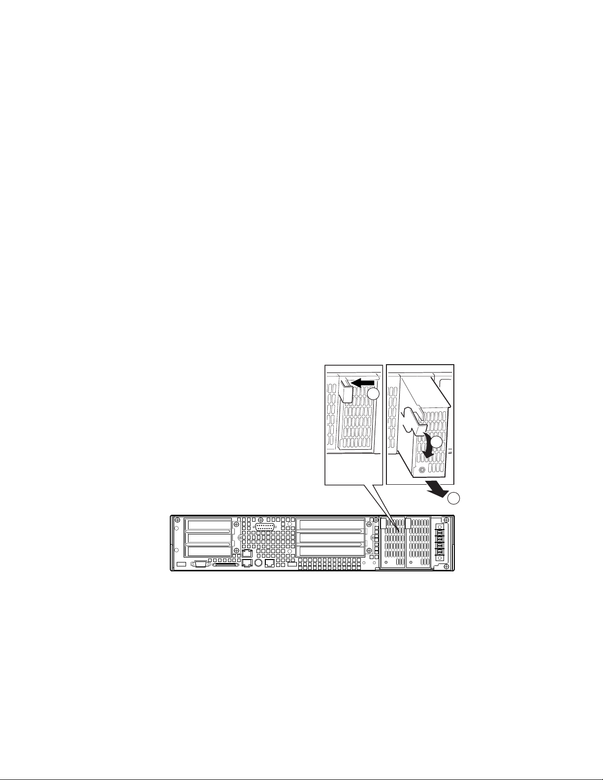
HP cc3300 Carrier Grade Server Product Guide
Electrostatic discharge (ESD) and ESD protection: ESD can
damage disk drives, boards, and other parts. We recommend that you
perform all procedures in this chapter only at an ESD workstation. If one is
not available, provide some ESD protection by wearing an antistatic wrist
strap attached to chassis ground (any unpainted metal surface) on your server
when handling parts.
ESD and handling boards: Always handle boards carefully. They can
be extremely sensitive to ESD. Hold boards only by their edges. After
removing a board from its protective wrapper or from the server, place the
board component side up on a grounded, static free surface. Use a
conductive foam pad if available but not the board wrapper. Do not slide
board over any surface.
Replacing Power Supply Modules
To replace an AC or DC power supply module, follow this procedure:
1. Depress the locking tab (A in Figure 11).
2. Rotate the handle downward (B in Figure 11).
3. Using the handle, pull the power supply outward (C in Figure 11).
4. Reverse these steps for installation.
A
B
C
OM12823
Figure 11. Unlocking and Removing the Power Supply Modules
66 Upgrading the Hardware
Page 67
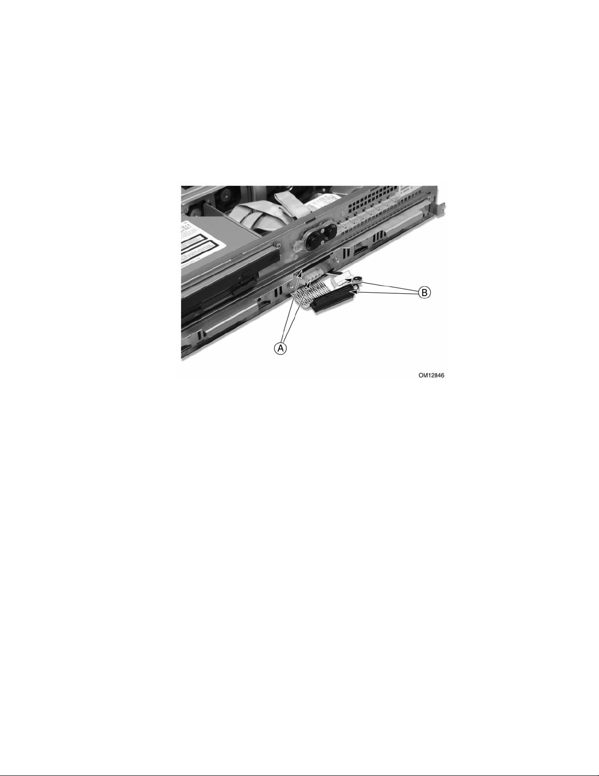
HP cc3300 Carrier Grade Server Product Guide
Replacing Hard Disk Drives
To replace a hard disk drive, follow this procedure:
1. Remove the bezel.
2. Disconnect the cables (B in Figure 12) from the connectors on the front of the hard disk drive
bay (A in Figure 12).
Figure 12. Disconnecting the Hard Disk Drive Bay Cables
3. Use the handles to pull the hard disk drive bay out of the chassis. Place it on a clean static-free
work surface.
Upgrading the Hardware 67
Page 68

HP cc3300 Carrier Grade Server Product Guide
4. Remove the two screws securing the cable retention bracket (A in Figure 13) and lift the
bracket out (B in Figure 13).
5. Disconnect the hard disk drive power cable (D in Figure 13).
6. Disconnect the hard disk drive ribbon cable (C in Figure 13).
7. Remove the three securing screws (E in Figure 13), lift the hard disk drive out of the hard disk
drive carrier, and place on a clean, static-free work surface.
Figure 13. Removing a Hard Disk Drive
Setting Hard Drive SCSI Addresses
The hard disk drive’s SCSI address needs to be set on any replacement or any additional disk drives
being installed in the server. Improper SCSI address settings can result in a boot failure if the SCSI
addresses are identical. Disk SCSI addresses are set to 5 and/or 6 at the factory.
Replacement Disks
The SCSI address jumpers need to be removed from the failed disk and installed on the replacement
disk. Set the SCSI address on the replacement disk to match the failed disk’s SCSI address.
Installing a Second Disk Drive in the Server Chassis
Check the SCSI address setting on the disk drive that is already installed. The SCSI address will be
5 or 6. Set the SCSI address on the second disk so it doesn’t match the SCSI address of the
currently installed disk drive. Failure to set the SCSI address properly could result in a SCSI
address conflict.
68 Upgrading the Hardware
Page 69

HP cc3300 Carrier Grade Server Product Guide
Disk Types
Different hard drives are used in the server. Please refer to the following information to determine
the disk type being replaced or installed.
Part Number A6942-69001/A6943-69001
Product Number A6942A/A6943A
Jumper Settings
Part Number A6917-69001/A6918-69001
Product Number A6917A/A6918A
Jumper Settings
Upgrading the Hardware 69
Page 70
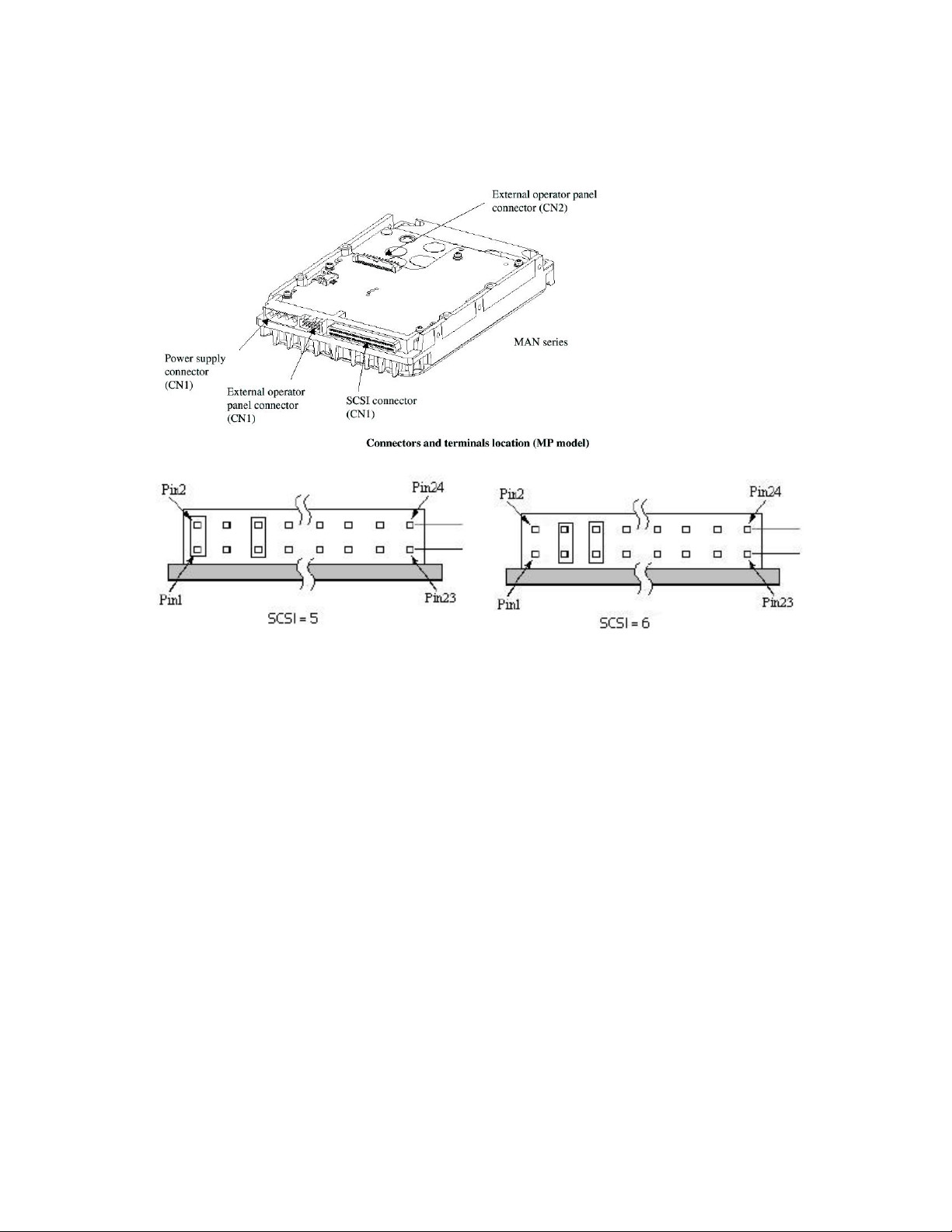
HP cc3300 Carrier Grade Server Product Guide
Working Inside the System
This section presents the following procedures that describe removal and installation of most
components inside the system.
Safety: Before You Remove Server Covers
Before removing covers at any time to work inside the system, observe these safety guidelines.
1. Turn off all peripheral devices connected to the system.
2. Power down the system by pressing and holding the Power button on the front of the chassis for
several seconds. After the server shuts down, unplug/disconnect the power cord to remove
standby power from the server.
3. Label and disconnect all peripheral cables and all telecommunication lines connected to
I/O connectors or ports on the back of the system.
Provide electrostatic discharge (ESD) protection by wearing an anti-static wrist strap attached to
chassis ground of the system-any unpainted metal surface-when handling components.
Warnings and Cautions
These warnings and cautions apply whenever you remove covers of the system.
70 Upgrading the Hardware
Page 71

WARNINGS
Power Button: Shutting down the server with the Power button on the
front of the chassis DOES NOT remove all power from the system. To
remove all power from system, you must also unplug/disconnect the
power cord from the system. Unplugging/disconnecting the power cord
from the system removes the +12 Volt standby power that is present
when the server is powered down.
Hazardous conditions, power supply: Hazardous voltage, current,
and energy levels are present inside the power supply. There are no
user-serviceable parts inside the power supplyHazardous conditions,
devices, and cables: Hazardous electrical conditions may be present
on power, telephone, and communication cables. Turn off the system
and unplug/disconnect the power cord, telecommunications systems,
networks, and modems attached to the system before opening it.
Otherwise, personal injury or equipment damage can result.
Hazardous conditions, processors and power supplies: Thermal
conditions may be present in the Processor/Memory Complex. Allow all
fans to continue to run until they shut down on their own after power
has been turned off. After the fans stop, you can unplug/disconnect the
power cord.
HP cc3300 Carrier Grade Server Product Guide
CAUTIONS
Electrostatic discharge (ESD) and ESD protection: ESD can
damage disk drives, boards, and other parts. We recommend that you do all
procedures in this section only at an ESD-protected workstation. If one is
not available, provide some ESD protection by wearing an anti-static wrist
strap attached to chassis groundany unpainted metal surfaceon your
system when handling parts.
ESD and handling boards: Always handle boards carefully. They can
be extremely sensitive to ESD. Hold boards only by their edges. After
removing a board from its protective wrapper or from the system, place it on
a grounded surface free of static electricity. Do not slide boards over any
surface.
Cooling and airflow: For proper cooling and airflow, always install the
chassis covers before turning on the system. Operating the system without
the covers in place can damage system parts.
Upgrading the Hardware 71
Page 72

HP cc3300 Carrier Grade Server Product Guide
Removing and Installing the Top Cover
CAUTION
For proper cooling and airflow, do not operate the server with the cover
removed. Always reinstall the cover before turning the server on.
The server comes with a removable Top Cover. Removal of this cover is necessary when installing
or removing many components. You do not have to remove the Top Cover when removing or
installing power supplies or hard drives.
WARNING
If rack mounted, make sure that the rack is anchored securely so it will
not tilt forward when the server chassis is extended. A crush hazard
exists should the rack tilt forward that could cause serious injury.
Only use a screwdriver tip to push in the lock tabs on the rack slides. A
pinch hazard exists if fingers are used for this purpose.
To remove the top cover, follow this procedure:
1. Remove the four screws along the rear panel (A in Figure 14) that secure the top cover to the
chassis.
2. Slide the top cover rearward (B in Figure 14) to release it from the chassis.
3. Lift the top cover up to remove.
Figure 14. Removing the Top Cover
72 Upgrading the Hardware
Page 73

HP cc3300 Carrier Grade Server Product Guide
Internal Chassis Layout
The server board contains connectors for installing up to two Pentium III processors utilizing the
FCPGA sockets. The server board has 6 DIMM slots and supports up to 6 GB error checking and
correcting (ECC) SDRAM memory. The server board also contains 6 PCI slots (implemented via
riser cards), input/output (I/O) ports and various controllers.
A Power Supply Cage E 3.3 PCI Add-in Card Riser
B Server Board F Fan Bracket
C 5 V PCI Add-in Card Riser G SCSI Hard Disk Drive Tray
D Fan Module H Peripheral Bay
Figure 15. Internal Chassis Layout
The server board is mounted horizontally toward the rear of the chassis behind the system fan array.
Up to two, 1.0-inch SCSI Ultra 160 hard drives can be mounted in the hard drive tray that is
mounted at the bottom front of the chassis. Above the hard drive tray and to the left are located the
peripheral drives that consist of a slim-line (1/2-inch) floppy drive, and a slim-line (1/2-inch)
CD-ROM drive.
The front panel is located above the hard drive tray and provides user interface for system
management.
Upgrading the Hardware 73
Page 74

HP cc3300 Carrier Grade Server Product Guide
Removing and Installing Memory
The server board supports only PC133-compliant SDRAM. DIMMs must be the same speed. Install
from 128 MB to 6 GB of registered memory. DIMMs must be installed in pairs in the following
order: 1A-1B, 2A-2B, and 3A-3B as shown in Figure 16. The DIMM sockets are further identified
on the board’s silkscreen.
NOTE: It is recommended that HP tested memory is used when adding
memory capacity to the server.
1A
3A1B2B
2A
3B
OM11790
Figure 16. Installing DIMMs
74 Upgrading the Hardware
Page 75

HP cc3300 Carrier Grade Server Product Guide
Removing and Installing Processors
WARNING
If the server has been running, any installed processor and heat sink on
the processor board(s) will be hot. To avoid the possibility of a burn,
allow the unit to cool-down and be careful when removing or installing
server board components that are located near processors.
CAUTIONS
Processor must be appropriate: You may damage the server if you
install a processor that is inappropriate for your server. Make sure your
server can handle a newer, faster processor (thermal and power
considerations). For exact information about processor interchangeability,
contact your customer service representative.
ESD and handling processors: Reduce the risk of electrostatic
discharge (ESD) damage to the processor by doing the following: (1) Touch
the metal chassis before touching the processor or server board. Keep part of
your body in contact with the metal chassis to dissipate the static charge
while handling the processor. (2) Avoid moving around unnecessarily.
Upgrading the Hardware 75
Page 76
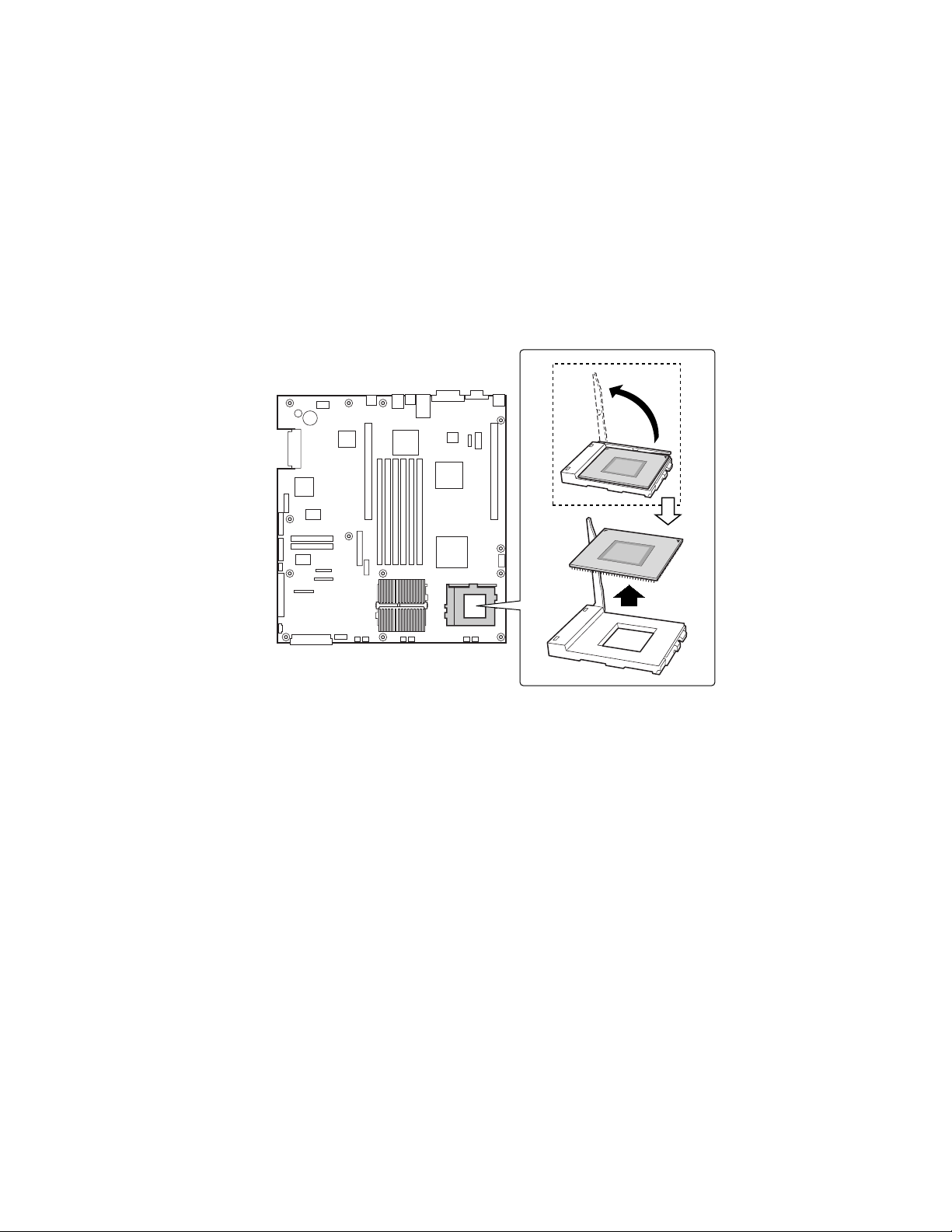
HP cc3300 Carrier Grade Server Product Guide
Adding a Processor
If you are adding a second processor to your system, you must first remove the terminator from the
secondary processor socket. The second processor must be compatible with the first processor
(within one stepping, same voltage & same speed)
1. Observe the safety and ESD precautions at the beginning of this chapter.
2. Remove the top cover.
3. Remove any PCI cards that may obscure the processors.
4. Raise the locking bar on the processor socket and remove the terminator as shown in
Figure 17).
OM11814
Figure 17. Raising the Locking Bar and Removing the Terminator
76 Upgrading the Hardware
Page 77

HP cc3300 Carrier Grade Server Product Guide
5. Using Figure 18 as a guide, align the corner mark on the processor with the corner mark on the
socket and insert the processor into the socket. Lower the locking bar completely and verify
that it has fully latched.
OM11789
Figure 18. Inserting the Processor and Lowering the Locking Bar
Upgrading the Hardware 77
Page 78

HP cc3300 Carrier Grade Server Product Guide
6. Apply the powerstrate strip to the top of the processor.
7. Align the processor and heatsink (D in Figure 19) so that the raised areas can make full contact
when assembled (the blades of the heatsink should point toward the fans).
8. Place the heatsink (B in Figure 19) on top of the processor (A in Figure 19).
9. Hook the heatsink retention clip (C in Figure 19) to one end of the processor socket. Using a
screwdriver or other tool, attach the other side of the clip to the other side of the processor
socket.
C
B
D
A
OM12826
Figure 19. Aligning the Heatsink and Installing the Heatsink Retaining Clip
78 Upgrading the Hardware
Page 79

HP cc3300 Carrier Grade Server Product Guide
Removing a Processor
1. Observe the safety and ESD precautions at the beginning of this chapter and the additional
cautions given here.
2. Detach the heatsink-retaining clip from the processor socket using a screwdriver or other tool
as shown in Figure 20.
OM12827
Figure 20. Unlatching the Heatsink Retaining Clip
3. Remove the heatsink and powerstrate from the processor.
4. Raise the locking bar on the socket as shown in Figure 21.
OM11788
Figure 21. Raising the Locking Bar on the Processor Socket
5. Remove the processor from the socket.
6. If you removed the processor from the secondary socket and are not replacing it, you must
install a terminator in its place.
Upgrading the Hardware 79
Page 80

HP cc3300 Carrier Grade Server Product Guide
Installing or Removing a Terminator
1. Observe the safety and ESD precautions at the beginning of this chapter and the additional
cautions given here.
2. Raise the locking bar (B in Figure 22) on the socket (A in Figure 22).
3. Align the corner marks on the terminator (C in Figure 22) along the locking bar side of the
processor socket.
4. Place the terminator into the socket.
5. Lower the locking bar (D in Figure 22) until it latches to the side of the processor socket.
6. Perform these steps in reverse to remove the terminator.
B
Figure 22. Installing a Terminator
C
A
D
OM11787
80 Upgrading the Hardware
Page 81

HP cc3300 Carrier Grade Server Product Guide
Replacing 3.3 Volt and 5 Volt PCI Add-in Cards
The server supports two types of PCI riser boards: 3.3 Volt and 5 Volt. The riser boards may be
installed in any combination of the two listed below such as two 5 Volt, or two 3.3 Volt, or one
3.3 Volt and one 5 Volt.
• The 5 Volt PCI riser supports three full-length, full-height 64-bit 33 MHz PCI add-in cards.
• The 3.3 Volt PCI riser supports three low profile, half-length, 64-bit, 66 MHz PCI add-in cards.
To replace the riser board, follow this procedure:
1. Remove the two screws securing the PCI retainer bracket.
2. Rotate the PCI retainer bracket to the left and slide out to remove.
3. Insert or remove the PCI add-in cards.
4. Replace the PCI retainer bracket. Make sure that it fully seats the PCI add-in cards.
Figure 23. Replacing 3.3 Volt or 5 Volt PCI Add-in Cards
Upgrading the Hardware 81
Page 82

HP cc3300 Carrier Grade Server Product Guide
PCI Add-in Card Cable Installation
It may be difficult to install a cable on the connector of a PCI add-in card configured at location A
in Figure 24 due to interference from the power supply. If this occurs, it may be necessary to move
the power supply cage out of the way, install the PCI cable on the PCI add-in card, then replace the
power supply.
To connect a PCI cable to a PCI add-in card under these circumstances, follow these instructions:
1. Remove the two screws (B in Figure 24) holding the power supply cage in place.
2. Lift the back of the power supply and rotate it (C in Figure 24) so that it is placed outside of the
unit. (This can be done without disconnecting the cable harness.)
3. Connect the cable to the PCI add-in card.
4. Replace the power supply cage and secure it with the two screws previously removed.
Figure 24. PCI Adapter Cable Installation
82 Upgrading the Hardware
Page 83

HP cc3300 Carrier Grade Server Product Guide
Replacing the Back Up Battery
The lithium battery on the server board powers the real time clock (RTC) for up to 10 years in the
absence of power. When the battery starts to weaken, it loses voltage, and the server settings stored
in CMOS RAM in the RTC (for example, the date and time) may be wrong.
WARNING
Danger of explosion if battery is incorrectly replaced. Replace only with
the same or equivalent type recommended by the equipment
manufacturer. Discard used batteries according to manufacturer’s
instructions.
ADVARSEL!
Lithiumbatteri - Eksplosionsfare ved fejlagtig håndtering. Udskiftning
må kun ske med batteri af samme fabrikat og type. Levér det brugte
batteri tilbage til leverandøren.
ADVARSEL
Lithiumbatteri - Eksplosjonsfare. Ved utskifting benyttes kun batteri
som anbefalt av apparatfabrikanten. Brukt batteri returneres
apparatleverandøren.
VARNING
Explosionsfara vid felaktigt batteribyte. Använd samma batterityp eller
en ekvivalent typ som rekommenderas av apparattillverkaren. Kassera
använt batteri enligt fabrikantens instruktion.
VAROITUS
Paristo voi räjähtää, jos se on virheellisesti asennettu. Vaihda paristo
ainoastaan laitevalmistajan suosittelemaan tyyppiin. Hävitä käytetty
paristo valmistajan ohjeiden mukaisesti.
Upgrading the Hardware 83
Page 84

HP cc3300 Carrier Grade Server Product Guide
To replace the backup battery, follow this procedure:
1. Observe the safety and ESD precautions at the beginning of this chapter.
2. Remove the top cover and locate the backup battery on the server board (see Figure 25).
3. Insert the tip of a small flat bladed screwdriver, or equivalent, under the tab in the plastic
retainer. Gently push down on the screwdriver to lift the battery.
4. Remove the battery from its socket.
5. Dispose of the battery according to local ordinance.
6. Remove the new lithium battery from its package, and, being careful to observe the correct
polarity, insert it in the battery socket.
7. Reinstall the plastic retainer on the lithium battery socket.
8. Replace the top cover.
9. Run Setup to restore the configuration settings to the RTC.
Figure 25. Replacing the Backup Battery
OM12830
84 Upgrading the Hardware
Page 85

5 Upgrading the Chassis
Replacing the Server Board
The replacement server board comes already installed in a chassis. Please note that warranty is
tracked by the serial and product number on your original system. Please record the serial and
product number of the original server you purchased and affix it to the replacement server. The
serial and product numbers together with the original sales order is used to confirm warranty
coverage.
1. Remove the top cover of the failed server.
2. Remove any PCI cards that may be installed in a 3.3 Volt or 5 Volt riser boards and place them
on a clean, static-free surface.
3. Unplug the PCI riser boards from the server board and place them on a clean, static-free
surface. (The upper brackets may be left attached to the riser boards.)
4. Remove the heatsink(s) and processor(s) from the server board and place them on a clean,
static-free surface.
5. Remove the memory DIMMs from the server board and place them on a static-free surface.
6. Remove the CDROM/Floppy assembly from the chassis and place it on a static-free surface.
7. Remove the disk tray and place it on a static-free surface.
8. Remove the power supplies and place on a static free met.
9. Place the replacement server on a static-free surface and install components that were removed
in steps 1 through 7.
10. Replace the top cover.
Upgrading the Hardware 85
Page 86

HP cc3300 Carrier Grade Server Product Guide
Replacing the CD-ROM and Floppy Assembly
To replace the CD-ROM and/or floppy disk drives, follow this procedure:
1. Remove the bezel.
2. Remove the three screws securing the fan bracket and remove.
3. Unplug and remove the 40 mm-fan module.
4. Disconnect the ribbon cable (A in Figure 26) from the server board.
5. Disconnect the power cable (B in Figure 26). You can access the power cable by loosening the
captive screw (C in Figure 26), and sliding the peripheral bay out an inch or two.
6. Disconnect the ribbon cable from the CD-ROM/floppy assembly. Slide the CD-ROM/floppy
assembly out through the front panel (D in Figure 26).
7. Install the replacement CD-ROM/floppy assembly.
Figure 26. Removing the Peripheral Bay from the Chassis
86 Upgrading the Hardware
Page 87

HP cc3300 Carrier Grade Server Product Guide
Replacing the Front Panel Board
To replace the front panel board, follow this procedure:
1. Disconnect the small ribbon cable (A in Figure 27).
2. Disconnect the large ribbon cable (B in Figure 27).
3. Remove the screw (C in Figure 27) and release the snap-on fasteners (D in Figure 27).
4. Lift out the board and place it on a clean, static-free surface.
5. To install the new board, repeat the instructions above in reverse order.
Figure 27. Front Panel Removal
Technical Reference 87
Page 88

HP cc3300 Carrier Grade Server Product Guide
Replacing Fans
Replacing an 80 mm Fan
To replace an 80 mm fan, follow this procedure:
1. Loosen the three screws that secure the fan bracket and remove.
2. Disconnect the fan power cable from the server board (A in Figure 28).
3. Slide the fan upward (B in Figure 28) out of the fan housing.
4. When replacing fans, note the airflow arrow (C in Figure 28) on the fan. The airflow arrow
should be pointing rearward toward the processors.
Figure 28. Replacing 80 mm Fans
88 Upgrading the Hardware
Page 89

HP cc3300 Carrier Grade Server Product Guide
Replacing a 40 mm Fan
To replace a 40 mm fan, follow this procedure:
1. Remove the three screws that secure the fan bracket and lift it out of the chassis.
2. Disconnect the fan power cables from both fans (A in Figure 28).
3. Slide the 40 mm fan module upward (B in Figure 28) out of the server.
4. Slide the fan (C in Figure 28) out of the 40 mm fan module.
5. When replacing fans, note the airflow arrow on the fan. The airflow arrow should be pointing
rearward toward the processors.
Figure 29. Replacing 40 mm Fans
Technical Reference 89
Page 90

HP cc3300 Carrier Grade Server Product Guide
Removing the Power Supply Cage
To replace the power supply cage, follow these instructions:
1. Remove the front bezel.
2. Disconnect the power cable and SCSI cable from the drive tray.
3. Remove the drive tray.
4. Remove the cable hold-down bracket located underneath the drive tray.
5. Disconnect the power connector from the floppy/CD-ROM signal cable.
6. Disconnect and remove the 40 mm fan array (A in Figure 30).
7. Disconnect the server board’s main power connector and peripheral power connectors (B in
Figure 30).
8. Remove the two securing screws (C in Figure 30) from the power supply cage.
9. Lift out the power supply cage (D in Figure 30).
Figure 30. Removing the Power Supply Cage
90 Upgrading the Hardware
Page 91

HP cc3300 Carrier Grade Server Product Guide
Replacement Parts
This section has a list of spare parts that can be ordered from Hewlett-Packard.
Exchange
Part Number
A6900-40001 Bezel, Front
A6900-67004 40mm Fan
A6900-67005 80mm Fan
A6900-67006 A6900-69006 Cage, AC Pwr Supply
A6900-67007 A6900-69007 PCA, Front Panel
A6900-67008 Cable, 24" Ultra 3 SCSI
A6900-67009
A6900-67010 Cable, 26" Alarm
A6900-67011 Cable, 12.8" Ultra 3 SCSI
Part Number
Description
A6900-67012 Cable, 8.5" Power
A6900-67013 Cable, 15" Front Panel
A6900-67015 Tray, Hard Drive Mounting
A6900-67016 Bracket, PCI Riser Card Mounting
A6900-67017 Bracket, HDD tray SCSI cable retention
A6900-67018 Cantilever Support
A6908-67003 Powerstrate Heat Dissipation Strip
A6898-63001 Y-Cable, PS2 Splitter 8"
A6900-67033 A6900-69033 System Board/Chassis, DC Power
A6901-67002 A6901-69002 System Board/Chassis, AC Power
A6906-67001 A6906-69001 Power Supply, AC
A6907-67001 A6907-69001 Power Supply, DC
A6908-67001 A6908-69001 1.26GHz Pentium III Proc w/512K Cache
A6908-67002 Heatsink w/locking clip
A6950-67001 Memory, DIMM, 2 x 128MB
A6909-67001 A6909-69001 Memory, DIMM, 2x256MB
A6910-67001 A6910-69001 Memory, DIMM, 2x512MB
A6916-67001 A6916-69001 Memory, DIMM, 2x1024MB
A6917-67001 A6917-69001 Disk Drive, 18GB 10K RPM
A6918-67001 A6918-69001 Disk Drive, 36GB 10k RPM
A6942-67001 A6942-69001 Disk Drive, 18GB 15k RPM
A6943-67001 A6943-69001 Disk Drive, 36GB 15k RPM
Technical Reference 91
Page 92

HP cc3300 Carrier Grade Server Product Guide
A6919-62001 I/O Card, Ultra 160, FW Full Height
A6919-62002 I/O Card, Ultra 160, FW Low Profile
A6920-62001 LAN Adapter, 10/100baseTX, Full Height
A6920-62002 LAN Adapter, 10/100baseTX, Low Profile
A6921-62001 LAN Adapter, Gigabit, Over Copper, Low Profile
A6921-62002 LAN Adapter, Gigabit, Over Copper, Full Height
A6927-04001 Assembly, Floppy/CDROM Drive(s)
A6928-67001 PCI Riser PCA, 3.3V
A6929-67001 PCI Riser PCA, 5.0V
A6905-67001 19" 2 Post rackmount kit
A6900-63001 DC External Pwr Cord
A6900-62003 Terminator, processor
A6898-70001 Screw, chassis
92 Upgrading the Hardware
Page 93

6 Technical Reference
This section includes:
• Connector pinouts
• Information on jumpers
Connector Pinouts
This section describes certain I/O interface connectors of the cc3000 Carrier Grade Server.
Alarms
The alarms port interface is a standard DB15-pin connector (see Figure 31). This connector allows
remote display of alarm conditions. Each alarm (Major, Minor, Critical and Power) is the output of
a STDT relay contact. A common contact with normally open and normally closed connections is
included. Power alarm has just a common and normally open contact outputs. The major and
minor alarms contain external reset circuits. Table 15 gives the pinout of the alarms connector.
CAUTION
Do not apply more than 60 Volts (maximum) to any pin or combination of
pins on the Alarms connector.
18
915
Figure 31. 15-pin Alarms Connector
Table 15. Alarms Connector Pinout
Pin Description Pin Description
1 Minor reset positive 9 Minor alarm normally closed
2 Minor reset negative 10 Minor alarm common
3 Major reset positive 11 Major alarm normally open
4 Major reset negative 12 Major alarm normally closed
5 Critical alarm normally open 13 Major alarm common
6 Critical alarm normally closed 14 Power alarm normally o pen
7 Critical alarm common 15 Power alarm common
8 Minor alarm normally open
Upgrading the Hardware 93
Page 94

HP cc3300 Carrier Grade Server Product Guide
DC Power Input for DC-Input Power Supply Cage
A DC power terminal block is provided at the rear of the DC-input power supply cage. It is
recommended to use appropriately sized power wire and DC mains.
Figure 32. DC Power Input Connector
The terminal block will accept standard terminal lugs size Newark* stock # 81N1501 type
CRS-T0-1406-HT that accept 14 AWG wire gauge. The width (W in Figure 33) of the lug can be
no larger than 0.25 inches.
Figure 33. DC Power Terminal Lug
To connect the earth ground conductor to the chassis:
1. Remove cover screw from right hand side of chassis.
2. Reinsert screw with grounding conductor attached.
Figure 34. DC Power Terminal Connectors
94 Upgrading the Hardware
Page 95

HP cc3300 Carrier Grade Server Product Guide
Serial Port
One serial port is provided on the rear I/O to supply COM2 using an 8-pin RJ45 connector (see
Table 16). The COM2 serial port can be used either as an emergency management port or as a
normal serial port. As an emergency management port (EMP), COM2 is used as a communication
path by the server management software that provides a level of emergency management through
an external modem. Figure 35 describes the serial port’s connections.
Figure 35. Serial Port Connector
Table 16. Serial Port Connector Pinout
Pin Signal Description
1 RTS Request to send
2 DTR Data terminal ready
3 TXD Transmit data
4 GND Ground
5 RIA Ring indicator
6 RXD Receive data
7 DSR/DCD Date set ready / data carrier detect1
8 CTS Clear to send
1
Use jumper on server board to select
Upgrading the Hardware 95
Page 96

HP cc3300 Carrier Grade Server Product Guide
Configuration Jumpers
This section describes the jumper blocks that control various configuration options. Figure 36
shows the names and location of the configuration jumpers. The shaded areas show the default
jumper placement for each configurable option. Table 17 describes the system recovery and update
jumper options.
OM12837
DSR to Pin #7
DCD to Pin #7
A
B
C
D
J6A2
DSR DCD
J1E1
BMC
WP
CMOS
CLR
PSWD
CLR
RCVRY
BOOT
Figure 36. Jumper Locations (J1E1 and J6A2)
System Recovery and Update Jumpers (J1E1)
Table 17. System Recovery and Update Jumper Options
Option Description
BMC Write
Protect
CMOS Clear If pins 4 and 5 are jumpered (default), preservation of configuration CMOS through
Password Clear If pins 7 and 8 are jumpere d (defau lt), the current system password is maintained
Recovery Boot If pins 10 and 11 are jumpered (default) the system will attempt to boot using the BIOS
96 Upgrading the Hardware
If pins 2 and 3 are jumpered (default), the BIOS boot block is write-protected. If pins 1
and 2 are jumpered, the boot block is erasable and programmable. WARNING:
Incorrect programming of the boot block will render the system unbootable. With
this option set to its default factory setting, the BMC’s operational code can still be
programmed without moving the jumper.
system reset is controlled by the BMC. If pins 5 and 6 are jumpered, CMOS contents
are set to the manufacturing default during system reset.
during system reset. If pins 8 and 9 are jumpered, the password is cleared on reset.
programmed in the Flash memory. If pins 11 and 12 are jumpered, the BIOS will
attempt a recovery boot, loading BIOS code from a CD-ROM disk into the Flash device.
This feature is typically used when the BIOS code has been corrupted.
Page 97

HP cc3300 Carrier Grade Server Product Guide
DSR/DCD Configuration Jumper (J6A2)
For serial concentrators that require a DCD signal, configure the J6A2 jumper block as shown in
Figure 37.
J6A2
OM12841
Figure 37. J6A2 Jumper Block Configured for DCD Signal
For serial concentrators that require a DSR signal, configure the J6A2 jumper block as shown in
Figure 38.
J6A2
OM12842
Figure 38. J6A2 Jumper Block Configured for DSR Signal (Default)
Upgrading the Hardware 97
Page 98

Page 99

A POST Error Codes and Messages
The following table defines POST error codes and their associated messages. The BIOS will
prompt the user to press a key in case of serious errors. The string “Error” precedes some error
messages to highlight possible system malfunctions. The BIOS vendor specific error codes are not
listed here since not all error codes are applicable to every platform. All POST errors and warnings
are logged in the system event log unless it is full.
After the video adapter has been successfully initialized, the BIOS indicates the current testing
phase during POST by writing a 2-digit hex code to I/O location 80h. If a Port-80h card (Postcard
is installed, it displays this 2-digit code on a pair of hex display LEDs.
Table 18. Port-80h Code Definition
Code Meaning
CP AMI* check point (port-80) code
Table 19. Boot Block POST Codes
Checkpoint
Code
D0h The NMI is disabled. Power-on delay is starting. Next, the initialization code checksum
D1h Initializing the DMA controller, performing the keyboard controller Basic Acceptance Test
D3h Starting memory sizing next.
D4h Returning to real mode. Executing any OEM patches and setting the stack next.
D5h Passing control to the uncompressed code in shadow RAM. The initialization code is
D6h Control is in segment 0. Next verifying the system BIOS checksum.
D7h Passing control to the interface module next.
D8h The main system BIOS runtime code will be decompressed next.
D9h Passing control to the main system BIOS in shadow RAM next.
03h The NMI is disabled. Next, checking for a soft reset or a power-on condition.
05h The BIOS stack has been built. Next, disabling cache memory.
06h Uncompressing the POST code next
Description
will be verified.
(BAT) test, starting memory refresh, and entering 4 GB flat mode next.
copied to segment 0 and control will be transferred to segment 0.
If the system BIOS checksum is bad, go to checkpoint code E0h.
Otherwise, going to checkpoint code D7h.
†
)
Post Error Codes and Messages 99
Page 100

HP cc3300 Carrier Grade Server Product Guide
Table 20. POST Code - Port 80h Codes
Post
Code Diagnostic LED Decoder Description
MSB LSB
07h Off G G G Uncompress various BIOS modules.
08h G Off Off Off Verify password checksum.
08h G Off Off Off Verify CMOS checksum.
07h Off G G G Read microcode updates from BIOS ROM.
07h Off G G G
0Bh G Off G G Hook before the keyboard BAT command is issued.
0Ch G G Off Off
0Eh G G G Off
0Fh G G G G
10h Off Off Off R
10h Off Off Off R Disable and initialize 8259.
11h Off Off Off A Detect configuration mode, such as CMOS clear.
13h Off Off G A Chipset initialization before CMOS initialization.
19h G Off Off A
1Ah G Off G R
23h Off Off A G
24h Off G R Off
25h Off G R G Init interrupt Vectors: interrupt vector initialization is done.
F2h R R A R Initialize SMM handler. Initialize USB emulation.
F5h R A R A Validate NVRAM areas. Restore from backup if corrupted.
12h Off Off G R
Note: G=Green, R=Red, A=Amber
Initializing the processors. Set up processor registers. Select least
featured processor as the BSP.
Keyboard Controller Test: the keyboard controller input buffer is
free. Next, issuing the BAT command to the keyboard controller.
Init after keyboard test: the keyboard controller BAT command
result has been verified. Next, performing any necessary
initialization after the keyboard controller BAT command test.
Write Command Byte 8042: the initialization after the keyboard
controller BAT command test is done. The keyboard command byte
will be written next.
Keyboard Init: the keyboard controller command byte is written.
Next, issuing the pin 23 and 24 blocking and unblocking commands.
Init System Timer: the 8254 timer test is over. Starting the memory
refresh test next.
Check Refresh Toggle: the memory refresh line is toggling.
Checking the 15 second on/off time next.
Setup Interrupt Vectors: reading the 8042 input port and disabling
the MEGAKEY Green PC feature next. Making the BIOS code
segment writable and performing any necessary configuration
before initializing the interrupt vectors.
Before Vector: configuration is required before interrupt vector
initialization has completed. Interrupt vector initialization is about to
begin.
Load defaults in CMOS RAM if bad checksum or CMOS clear
jumper is detected.
100 Post Error Codes and Messages
 Loading...