

Page 1
Product End-of-Life Disassembly Instructions
Marketing Name / Model
[List multiple models if applicable.] Product Category - Servers
Product Name
HP Integrity Superdome 2 CB900s i4 Server Blade
Model:
CB900s i4 Server Blade
Purpose: The document is intended for use by end-of-life recyclers or treatment facilities. It provides the basic instructions for the disassembly of
HP products to remove components and materials requiring selective treatment.
1.0 Items Requiring Selective Treatment
1.1 Items listed below are classified as requiring selective treatment.
1.2 Enter the quantity of items contained within the product which require selective treatment in the right column, as applicable.
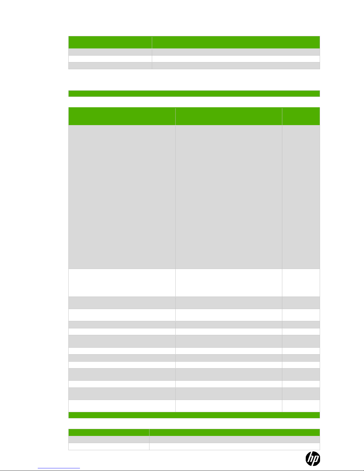
Item Description Notes
Quantity of
items included
in product
Printed Circuit Boards (PCB) or Printed Circuit Assemblies
(PCA)
Server is configurable and may contain some of the
following assemblies.
AH342-2006C (AT121A, AT122A, AT123A, AT124A)
CB900s i4 Blade
AT085-2022A, POULSON CPU 2.53GHz/8-core/32M
AT085-2021A, POULSON CPU 2.13GHz/8-core/24M
605313-371 (AT127A, AT129A), DDR3 8G DIMM
AH342-2005C (AM253A, AM255A, AM254A,
AM256A), CB900s i2 Blade
AH339-2029A, TUK CPU 1.60GHZ
AH339-2030A, TUK CPU 1.73GHZ
519750-371 (AH340A, AH377A), DDR3 4G DIMM
AH337-60108, CAMNet Only Blade
AH337-60502, Upper Midplane
012686-502, Lower Signal Midplane
AH337-60305, DVD Module
AH337-60604, GPSM
408439-502, Assy Fan PCA
012913-502, PCA, PWR MOD
012958-502, PCA, LCD Blindmate Paddle
012955-601, PCA, LCD Pass Thru Crd-Edge
407295-502, Assy, Management Sleeve
AH341-60401, XFM
AH389-60001, Onboard Administrator
AH337-2030B, ASSY, E-Switch Module
AT064A, HP ProCurve 6120XG Blade Switch
310
(maximum)
Batteries All types including standard alkaline and lithium coin or
button style batteries
1420-0356 (PDH) Blade
1420-0356 (GXE) Blade
M4T28-BR12SH1TR OA
20
(maximum)
Mercury-containing components For example, mercury in lamps, display backlights, scanner
lamps, switches, batteries
Liquid Crystal Displays (LCD) with a surface greater than
100 sq cm
Includes background illuminated displays with gas
discharge lamps
Cathode Ray Tubes (CRT)
Capacitors / condensers (Containing PCB / PCT)
Electrolytic Capacitors / Condensers measuring greater
than 2.5 cm in diameter or height
Per Power Supply 2 or 4
External electrical cables and cords
Gas Discharge Lamps
Plastics containing Brominated Flame Retardants
Components and parts containing toner and ink, including
liquids, semi-liquids (gel/paste) and toner
Include the cartridges, print heads, tubes, vent chambers,
and service stations.
Components and waste containing asbestos
Components, parts and materials containing refractory
ceramic fibers
Components, parts and materials containing radioactive
substances
2.0 Tools Required
List the type and size of the tools that would typically be used to disassemble the product to a point where components and materials requiring
selective treatment can be removed.
Tool Description Tool Size (if applicable)
Torx screw drivers T6, T10, T15 & T25
Flat Blade Screwdriver
Page 2

Description #3
Description #4
Description #5
3.0 Product Disassembly Process
3.1 List the basic steps that should typically be followed to remove components and materials requiring selective treatment:
1. Compute enclosure front components (See Figure 1)
2. Compute Enclosure Rear Components (See Figure 2)
3. Remove power supplies
• Press the release button
• Pull down the handle
• Remove the power supply (quantity 12) (SEE Figure 3)
4. Removing DVD Module
• Remove USB cables from DVD to OA
• Remove the DVD module bezel
• Press the button on the front of the DVD module to release handle
• Pull the handle and slide the DVD module out enclosure (SEE Figure 4)
5. Remove the Server Blades(s)
• CAUTION: After you press the release buttons, the server blade is unlocked from the enclosure. Use both hands to support the server
blade when you remove it from the enclosure. The Server Blade weighs approximately 15.4 kg (34 lb) (SEE Figure 5)
• Lay Server Blade on flat surface
• Remove the access panel by lifting it straight up and off the server Blade (SEE Figure 6)
• Locate the two processors
o Disconnect power cord from CPU assembly
o For CPU0 removal, remove the air baffle
o Rotate the processor locking handle up and back until it reaches a hard stop
o Pull the processor and heatsink off of the socket (SEE Figure 7)
o Remove the DIMMs, maximum quantity 32 (SEE Figure 8)
o Remove the two batteries (SEE Figure 9)
6. Remove the active cool fans, quantity 15
• Turn the handle counterclockwise
• Remove the fan
7. Remove the interconnect switch (maximum quantity 8)
• Disconnect all cables from component
• Press the release tab
• Open the handle
• Remove the interconnect switch (See figure 2 for location)
8. Remove Onboard Administrator modules (quantity 2) and Onboard Administrator tray
• Disconnect all cables
• Press the release tab and open handle and remove onboard administrator; quantity 2 (See Figure 2 for location)
• On the Onboard Administrator Modules that were removed, depress the button in the center and remove the top panel.
o Remove the PCB and look for the Yellow battery. This battery can be removed from its corresponding IC by using
your fingers.
(See Figure 10)
• Press the release handle on the onboard administrator tray and open handle. Note: This is the assembly that the onboard
administrator installs into (See Figure 11)
9. Remove the GPSMs
• Disconnect all cables
• Press the button on the front of the GPSM to release handle
• Pull the handle and slide the GPSM out of the enclosure
10. Remove the XFM; quantity of 4
• Disconnect all X-Bar Flex-connect cables
• Press buttons on the front of the XFM to release the handles
• Pull the handles and slide the XFM out of the enclosure
11. Remove the ac input modules
• Completely unscrew the three thumbscrews that secure the ac input module. The screws remain captive after they are unscrewed
• Remove the ac input modules (See Figure 2 for location; See Figure 12 for component removal)
12. Remove the I/O Chassis (Enclosure tear down)
• Unscrew the ten thumbscrews and open the hinges completely
• Use the handles to extend the I/O chassis until the release levers engage on both sides of the I/O Chassis
• Grasp the handholds below the release levers
• Disengage the release levers on both sides of the rear chassis
o CAUTION:
When removing and lifting the I/O chassis, always grasp the handholds as far forward as possible. The frontend
of the I/O chassis is heavy and the handholds provide a more balanced location to distribute the weight
• Use the handholds to extend and remove the I/O Chassis from the enclosure (See figure 13)
13. Remove the midplane brick assembly
• WARNING: At least two people are required to safely move the midplane to avoid personal injury
• Pull the plunger pins in each corner and rotate ¼ turn to lock them in position
• Use the handles to extend and remove the midplane assembly from the enclosure (See figure 14)
• Place midplane brick flat on table to allow disassembly
14. Disassemble midplane brick
• Remove status panel PCA (See Figure 15)
Page 3
• Remove Air Valve assemblies
o Remove 3 screws from each side. Lift out the air valve assemblies (See Figure 16)
• Remove Fan PCAs
o Disconnect cables to the 3 Fan PCA’s. Remove 3 screws from each fan PCA.
o Remove PCAs (See Figure 17)
• Unlatch DVD Cable (See Figure 18)
• Remove Airframe screws (See Figure 19)
• Remove Airframes and midplanes (See Figure 20)
• Remove the busbar assemblies (Figure 21)
• Remove power PCAs from busbar assemblies (Figure 22)
15. Remove power Supply covers
• Locate Capacitors greater than 2.5cm (Figure 23)
• Using a flat blade screwdriver pry capacitors from the supply; there will either be 2 or 4 per supply
• Note: There are two types of supplies and three vendors, Figure 23 will have examples of all
3.2 Optional Graphic. If the disassembly process is complex, insert a graphic illustration below to identify the items contained in the product
that require selective treatment (with descriptions and arrows identifying locations).
Page 4
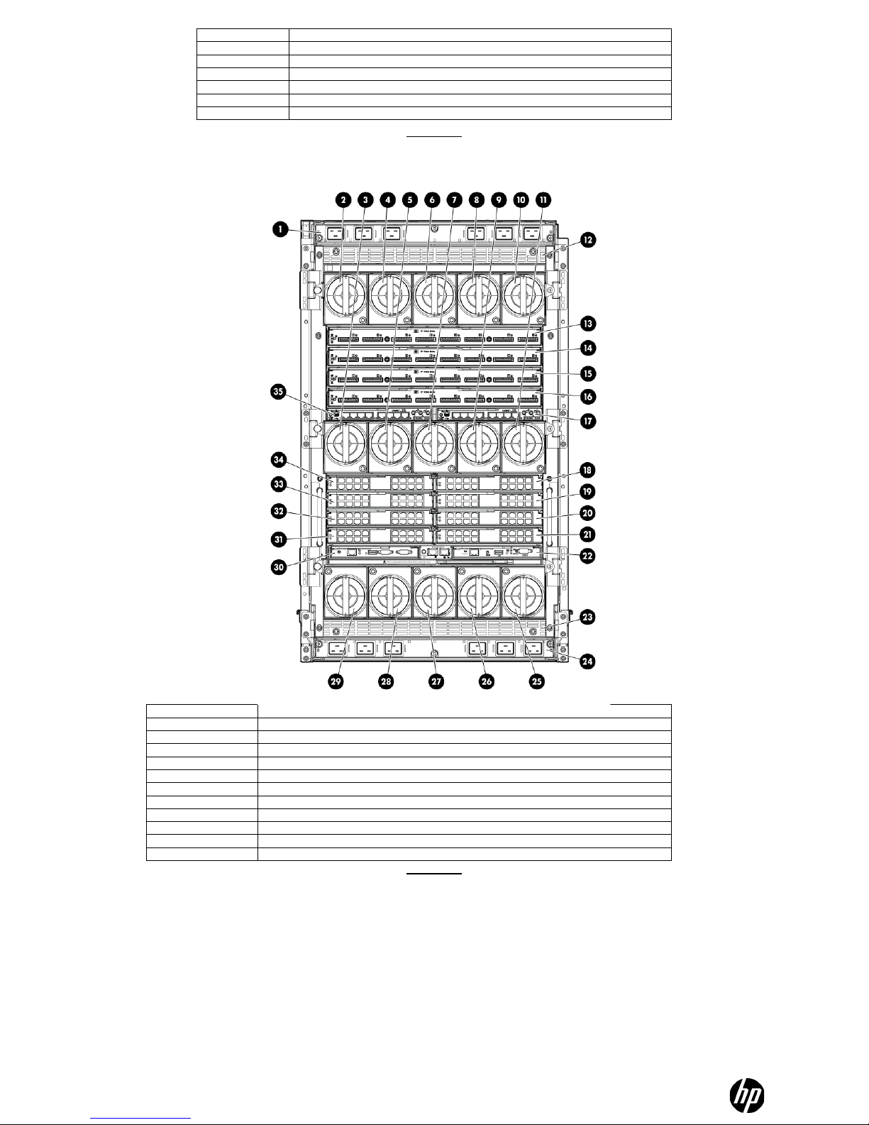
FIGURE 1
Item Description
1
AC power connectors (upper)
2-11
Fan bay 1 – 10
13 – 16 XFM Bay 1 – 4
17 GPSM 2
18 – 21 Interconnect Bay 2, 4, 6 & 8
22 Onboard Administrator 2
24 Ac power connectors (lower)
25 – 29 Fan bay 11 – 15
30 Onboard Administrator 1
31 – 34 Interconnect bay 1, 3, 5, 7
35 GPSM 1
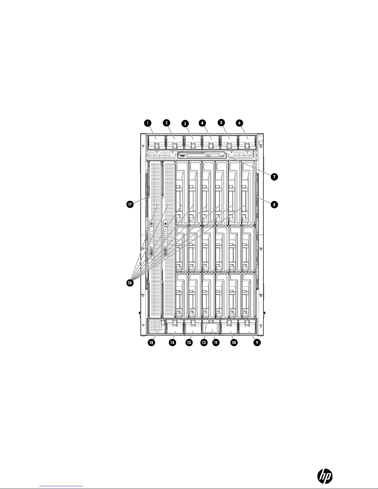
FIGURE 2
Item Description
1 thru 6 Power Supply Bay 7-12
7 DVD Module
9 & 10 Power Supply Bay 6-5
11 Insight Display
12 thru 15 Power Supply Bay 4 – 1
16 Blade slots
Page 5

FIGURE 3
FIGURE 4
FIGURE 5
Page 6

FIGURE 6
FIGURE 7
FIGURE 8
• Two batteries, item number 11 in above drawing
FIGURE 9
Page 7

FIGURE 10
FIGURE 11
FIGURE 12
There are ac input modules at the top and bottom of
the enclosure
Page 8

FIGURE 13
FIGURE 14
FIGURE 15
Page 9

FIGURE 16
FIGURE 17
FIGURE 18
Depress DVD connector latch,
slide connector to the right
and push it backwards to
disengage it from the
airframe.
Page 10

FIGURE 19
FIGURE 20
Upper
Midplane
Qt y 10
Lower
Midplane
Qt y 10
Remove screws and set
aside for reuse.
Remove upper and lower airframes.
Remove last midplane screw.
Remove midplanes
Unplug cables
(4 plc)
Unplug cables
(3 plc)
Remove midplanes.
Remove these four cables. Note the cable
routing through the cable clips.
Leave these 2 cables attached at
the bus bar.
Page 11

FIGURE 21
FIGURE 22
Leaving the cables attached to the busbar
assemblies, lift out the busbar assemblies
Page 12

FIGURE 23
 Loading...