

Page 1

service
Page 2

Page 3

output finishing devices:
hp LaserJet multifunction finisher, 3,000-sheet
stapler/stacker, 3,000-sheet stacker,
and 8-bin mailbox
service supplement__________
Page 4

Copyright and License
© 2004 Copyright HewlettPackard De v elopment Compan y,
LP
Reproduction, adaptation or
translation without prior written
permission is prohibited, except
as allowed under the copyright
laws.
Part number: Q5693-90002
Edition 1, 9/2004
The information contained herein
is subject to change without
notice.
The only warranties for HP
products and services are set
forth in the express warranty
statements accompanying such
products and services. Nothing
herein should be construed as
constituting an additional
warranty. HP shall not be liable
for technical or editorial errors or
omissions contained herein.
Trademark Credits
Adobe
®
and PostScript® are
trademarks of Adobe Systems
Incorporated.
MS-DOS
®
is a U.S. registered
trademark of Microsoft
Corporation.
E
NERGY STAR
®
is a U.S.
registered service mark of the
United States Environmental
Protection Agency.
Page 5

Contents 3
Contents
1 Product information
Product features. . . . . . . . . . . . . . . . . . . . . . . . . . . . . . . . . . . . . . . . . . . . . . . . . . . . . . . . . 16
Multifunction finisher (C8088A/C8088B). . . . . . . . . . . . . . . . . . . . . . . . . . . . . . . . . . . . . 16
3,000-sheet stapler/stacker (C8085A) . . . . . . . . . . . . . . . . . . . . . . . . . . . . . . . . . . . . . . 17
3,000-sheet stacker (C8084A) . . . . . . . . . . . . . . . . . . . . . . . . . . . . . . . . . . . . . . . . . . . . 17
8-bin mailbox (Q5693A) . . . . . . . . . . . . . . . . . . . . . . . . . . . . . . . . . . . . . . . . . . . . . . . . . 18
Identification . . . . . . . . . . . . . . . . . . . . . . . . . . . . . . . . . . . . . . . . . . . . . . . . . . . . . . . . . . . . 19
Multifunction finisher . . . . . . . . . . . . . . . . . . . . . . . . . . . . . . . . . . . . . . . . . . . . . . . . . . . 19
3,000-sheet stapler/stacker . . . . . . . . . . . . . . . . . . . . . . . . . . . . . . . . . . . . . . . . . . . . . . 20
3,000-sheet stacker . . . . . . . . . . . . . . . . . . . . . . . . . . . . . . . . . . . . . . . . . . . . . . . . . . . . 21
8-bin mailbox. . . . . . . . . . . . . . . . . . . . . . . . . . . . . . . . . . . . . . . . . . . . . . . . . . . . . . . . . . 22
Product overview . . . . . . . . . . . . . . . . . . . . . . . . . . . . . . . . . . . . . . . . . . . . . . . . . . . . . . . . 23
Multifunction finisher . . . . . . . . . . . . . . . . . . . . . . . . . . . . . . . . . . . . . . . . . . . . . . . . . . . 23
3,000-sheet stapler/stacker . . . . . . . . . . . . . . . . . . . . . . . . . . . . . . . . . . . . . . . . . . . . . . 25
3,000-sheet stacker . . . . . . . . . . . . . . . . . . . . . . . . . . . . . . . . . . . . . . . . . . . . . . . . . . . . 26
8-bin mailbox. . . . . . . . . . . . . . . . . . . . . . . . . . . . . . . . . . . . . . . . . . . . . . . . . . . . . . . . . . 27
Specifications . . . . . . . . . . . . . . . . . . . . . . . . . . . . . . . . . . . . . . . . . . . . . . . . . . . . . . . . . . . 28
Multifunction finisher . . . . . . . . . . . . . . . . . . . . . . . . . . . . . . . . . . . . . . . . . . . . . . . . . . . . 28
3,000-sheet stapler/stacker . . . . . . . . . . . . . . . . . . . . . . . . . . . . . . . . . . . . . . . . . . . . . . 29
3,000-sheet stacker . . . . . . . . . . . . . . . . . . . . . . . . . . . . . . . . . . . . . . . . . . . . . . . . . . . . 30
8-bin mailbox. . . . . . . . . . . . . . . . . . . . . . . . . . . . . . . . . . . . . . . . . . . . . . . . . . . . . . . . . . 31
Regulatory information . . . . . . . . . . . . . . . . . . . . . . . . . . . . . . . . . . . . . . . . . . . . . . . . . . . . 32
Declaration of Conformity—multifunction finisher . . . . . . . . . . . . . . . . . . . . . . . . . . . . . 32
Declaration of Conformity—3,000-sheet stapler/stacker . . . . . . . . . . . . . . . . . . . . . . . . 33
Declaration of Conformity—3,000-sheet stacker . . . . . . . . . . . . . . . . . . . . . . . . . . . . . . 34
Declaration of Conformity—8-bin mailbox . . . . . . . . . . . . . . . . . . . . . . . . . . . . . . . . . . . 35
Service approach . . . . . . . . . . . . . . . . . . . . . . . . . . . . . . . . . . . . . . . . . . . . . . . . . . . . . . . 36
Parts and supplies . . . . . . . . . . . . . . . . . . . . . . . . . . . . . . . . . . . . . . . . . . . . . . . . . . . . . 36
Exchange program . . . . . . . . . . . . . . . . . . . . . . . . . . . . . . . . . . . . . . . . . . . . . . . . . . . . . 36
Warranty . . . . . . . . . . . . . . . . . . . . . . . . . . . . . . . . . . . . . . . . . . . . . . . . . . . . . . . . . . . . . 36
2 Installation
Environmental requirements . . . . . . . . . . . . . . . . . . . . . . . . . . . . . . . . . . . . . . . . . . . . . . . 38
Physical requirements . . . . . . . . . . . . . . . . . . . . . . . . . . . . . . . . . . . . . . . . . . . . . . . . . . . . 39
Multifunction finisher . . . . . . . . . . . . . . . . . . . . . . . . . . . . . . . . . . . . . . . . . . . . . . . . . . . 39
3,000-sheet stapler/stacker and 3,000-sheet stacker . . . . . . . . . . . . . . . . . . . . . . . . . . 40
8-bin mailbox . . . . . . . . . . . . . . . . . . . . . . . . . . . . . . . . . . . . . . . . . . . . . . . . . . . . . . . . . 41
3 Operation
Supported media . . . . . . . . . . . . . . . . . . . . . . . . . . . . . . . . . . . . . . . . . . . . . . . . . . . . . . . . 44
Multifunction finisher . . . . . . . . . . . . . . . . . . . . . . . . . . . . . . . . . . . . . . . . . . . . . . . . . . . 44
3,000-sheet stapler/stacker . . . . . . . . . . . . . . . . . . . . . . . . . . . . . . . . . . . . . . . . . . . . . . 46
3,000-sheet stacker . . . . . . . . . . . . . . . . . . . . . . . . . . . . . . . . . . . . . . . . . . . . . . . . . . . . 46
8-bin mailbox. . . . . . . . . . . . . . . . . . . . . . . . . . . . . . . . . . . . . . . . . . . . . . . . . . . . . . . . . . 47
Using media . . . . . . . . . . . . . . . . . . . . . . . . . . . . . . . . . . . . . . . . . . . . . . . . . . . . . . . . . . . . 48
Multifunction finisher . . . . . . . . . . . . . . . . . . . . . . . . . . . . . . . . . . . . . . . . . . . . . . . . . . . 48
3,000-sheet stapler/stacker. . . . . . . . . . . . . . . . . . . . . . . . . . . . . . . . . . . . . . . . . . . . . . . 50
Page 6

4 Contents ENWW
4 Maintenance
Cleaning the outside of the product . . . . . . . . . . . . . . . . . . . . . . . . . . . . . . . . . . . . . . . . . . 52
Cleaning inside the product . . . . . . . . . . . . . . . . . . . . . . . . . . . . . . . . . . . . . . . . . . . . . . . . 52
5 Theory of operation
Power-on sequence . . . . . . . . . . . . . . . . . . . . . . . . . . . . . . . . . . . . . . . . . . . . . . . . . . . . . . 54
Multifunction finisher . . . . . . . . . . . . . . . . . . . . . . . . . . . . . . . . . . . . . . . . . . . . . . . . . . . . 54
3,000-sheet stapler/stacker . . . . . . . . . . . . . . . . . . . . . . . . . . . . . . . . . . . . . . . . . . . . . . 54
3,000-sheet stacker . . . . . . . . . . . . . . . . . . . . . . . . . . . . . . . . . . . . . . . . . . . . . . . . . . . . 54
8-bin mailbox . . . . . . . . . . . . . . . . . . . . . . . . . . . . . . . . . . . . . . . . . . . . . . . . . . . . . . . . . 55
Basic operation . . . . . . . . . . . . . . . . . . . . . . . . . . . . . . . . . . . . . . . . . . . . . . . . . . . . . . . . . 56
Multifunction finisher . . . . . . . . . . . . . . . . . . . . . . . . . . . . . . . . . . . . . . . . . . . . . . . . . . . . 56
Offset specifications . . . . . . . . . . . . . . . . . . . . . . . . . . . . . . . . . . . . . . . . . . . . . . . . . . . . 58
3,000-sheet stapler/stacker. . . . . . . . . . . . . . . . . . . . . . . . . . . . . . . . . . . . . . . . . . . . . . . 62
Offset specifications . . . . . . . . . . . . . . . . . . . . . . . . . . . . . . . . . . . . . . . . . . . . . . . . . . . . 65
3,000-sheet stacker. . . . . . . . . . . . . . . . . . . . . . . . . . . . . . . . . . . . . . . . . . . . . . . . . . . . . 66
Offset specifications . . . . . . . . . . . . . . . . . . . . . . . . . . . . . . . . . . . . . . . . . . . . . . . . . . . . 68
8-bin mailbox. . . . . . . . . . . . . . . . . . . . . . . . . . . . . . . . . . . . . . . . . . . . . . . . . . . . . . . . . . 69
Electric circuitry . . . . . . . . . . . . . . . . . . . . . . . . . . . . . . . . . . . . . . . . . . . . . . . . . . . . . . . . . 73
Power supply . . . . . . . . . . . . . . . . . . . . . . . . . . . . . . . . . . . . . . . . . . . . . . . . . . . . . . . . . . . 74
Multifunction finisher . . . . . . . . . . . . . . . . . . . . . . . . . . . . . . . . . . . . . . . . . . . . . . . . . . . . 74
3,000-sheet stapler/stacker . . . . . . . . . . . . . . . . . . . . . . . . . . . . . . . . . . . . . . . . . . . . . . 74
3,000-sheet stacker. . . . . . . . . . . . . . . . . . . . . . . . . . . . . . . . . . . . . . . . . . . . . . . . . . . . . 74
8-bin mailbox. . . . . . . . . . . . . . . . . . . . . . . . . . . . . . . . . . . . . . . . . . . . . . . . . . . . . . . . . . 75
Motors, solenoids, and clutches . . . . . . . . . . . . . . . . . . . . . . . . . . . . . . . . . . . . . . . . . . . . . 76
Multifunction finisher . . . . . . . . . . . . . . . . . . . . . . . . . . . . . . . . . . . . . . . . . . . . . . . . . . . . 76
8-bin mailbox. . . . . . . . . . . . . . . . . . . . . . . . . . . . . . . . . . . . . . . . . . . . . . . . . . . . . . . . . . 77
Sensors . . . . . . . . . . . . . . . . . . . . . . . . . . . . . . . . . . . . . . . . . . . . . . . . . . . . . . . . . . . . . . . 78
Multifunction finisher . . . . . . . . . . . . . . . . . . . . . . . . . . . . . . . . . . . . . . . . . . . . . . . . . . . . 78
3,000-sheet stapler/stacker. . . . . . . . . . . . . . . . . . . . . . . . . . . . . . . . . . . . . . . . . . . . . . . 83
3,000-sheet stacker. . . . . . . . . . . . . . . . . . . . . . . . . . . . . . . . . . . . . . . . . . . . . . . . . . . . . 84
8-bin mailbox. . . . . . . . . . . . . . . . . . . . . . . . . . . . . . . . . . . . . . . . . . . . . . . . . . . . . . . . . . 85
6 Removal and replacement
Introduction. . . . . . . . . . . . . . . . . . . . . . . . . . . . . . . . . . . . . . . . . . . . . . . . . . . . . . . . . . . . . 89
Removal and replacement strategy . . . . . . . . . . . . . . . . . . . . . . . . . . . . . . . . . . . . . . . . 89
Electrostatic discharge . . . . . . . . . . . . . . . . . . . . . . . . . . . . . . . . . . . . . . . . . . . . . . . . . . 89
Required tools. . . . . . . . . . . . . . . . . . . . . . . . . . . . . . . . . . . . . . . . . . . . . . . . . . . . . . . . . 89
Before performing service . . . . . . . . . . . . . . . . . . . . . . . . . . . . . . . . . . . . . . . . . . . . . . . . 90
Multifunction finisher external doors and covers . . . . . . . . . . . . . . . . . . . . . . . . . . . . . . . . 91
Stapler door . . . . . . . . . . . . . . . . . . . . . . . . . . . . . . . . . . . . . . . . . . . . . . . . . . . . . . . . . . 91
Product-release handle . . . . . . . . . . . . . . . . . . . . . . . . . . . . . . . . . . . . . . . . . . . . . . . . . 92
Folding knob . . . . . . . . . . . . . . . . . . . . . . . . . . . . . . . . . . . . . . . . . . . . . . . . . . . . . . . . . . 94
Handle-mounting gear . . . . . . . . . . . . . . . . . . . . . . . . . . . . . . . . . . . . . . . . . . . . . . . . . . 95
Front cover . . . . . . . . . . . . . . . . . . . . . . . . . . . . . . . . . . . . . . . . . . . . . . . . . . . . . . . . . . . 96
Back cover . . . . . . . . . . . . . . . . . . . . . . . . . . . . . . . . . . . . . . . . . . . . . . . . . . . . . . . . . . . 98
Upper panel assembly (top door) . . . . . . . . . . . . . . . . . . . . . . . . . . . . . . . . . . . . . . . . . . 99
Internal-path cover (dispose subcover) . . . . . . . . . . . . . . . . . . . . . . . . . . . . . . . . . . . . 100
Foot cover . . . . . . . . . . . . . . . . . . . . . . . . . . . . . . . . . . . . . . . . . . . . . . . . . . . . . . . . . . 101
Multifunction finisher assemblies . . . . . . . . . . . . . . . . . . . . . . . . . . . . . . . . . . . . . . . . . . . 102
Paper-guide wire . . . . . . . . . . . . . . . . . . . . . . . . . . . . . . . . . . . . . . . . . . . . . . . . . . . . . 102
Product-attachment latch . . . . . . . . . . . . . . . . . . . . . . . . . . . . . . . . . . . . . . . . . . . . . . . 103
Stapling unit . . . . . . . . . . . . . . . . . . . . . . . . . . . . . . . . . . . . . . . . . . . . . . . . . . . . . . . . . 104
Aligner racks . . . . . . . . . . . . . . . . . . . . . . . . . . . . . . . . . . . . . . . . . . . . . . . . . . . . . . . . . 105
Booklet bin-full sensor flag (main lever weight assembly) . . . . . . . . . . . . . . . . . . . . . . 106
Paper deflector (deflector weight) . . . . . . . . . . . . . . . . . . . . . . . . . . . . . . . . . . . . . . . . 107
Anti-static brush . . . . . . . . . . . . . . . . . . . . . . . . . . . . . . . . . . . . . . . . . . . . . . . . . . . . . . 109
Page 7

ENWW Contents 5
Stacker bin . . . . . . . . . . . . . . . . . . . . . . . . . . . . . . . . . . . . . . . . . . . . . . . . . . . . . . . . . .110
Booklet bin . . . . . . . . . . . . . . . . . . . . . . . . . . . . . . . . . . . . . . . . . . . . . . . . . . . . . . . . . .111
Stapling-door switch . . . . . . . . . . . . . . . . . . . . . . . . . . . . . . . . . . . . . . . . . . . . . . . . . . .113
Interlock switch . . . . . . . . . . . . . . . . . . . . . . . . . . . . . . . . . . . . . . . . . . . . . . . . . . . . . . .114
Flipper assembly . . . . . . . . . . . . . . . . . . . . . . . . . . . . . . . . . . . . . . . . . . . . . . . . . . . . . .115
Folding mechanism . . . . . . . . . . . . . . . . . . . . . . . . . . . . . . . . . . . . . . . . . . . . . . . . . . . .117
User LED PCA . . . . . . . . . . . . . . . . . . . . . . . . . . . . . . . . . . . . . . . . . . . . . . . . . . . . . . .120
Controller PCA . . . . . . . . . . . . . . . . . . . . . . . . . . . . . . . . . . . . . . . . . . . . . . . . . . . . . . .121
Service LED PCA . . . . . . . . . . . . . . . . . . . . . . . . . . . . . . . . . . . . . . . . . . . . . . . . . . . . .123
Power supply . . . . . . . . . . . . . . . . . . . . . . . . . . . . . . . . . . . . . . . . . . . . . . . . . . . . . . . . .124
Jet-Link cable (interface cable) . . . . . . . . . . . . . . . . . . . . . . . . . . . . . . . . . . . . . . . . . . .125
Adjustable casters (left side) . . . . . . . . . . . . . . . . . . . . . . . . . . . . . . . . . . . . . . . . . . . . .126
Stationary extended caster (back right) . . . . . . . . . . . . . . . . . . . . . . . . . . . . . . . . . . . . .127
Stationary caster (front right) . . . . . . . . . . . . . . . . . . . . . . . . . . . . . . . . . . . . . . . . . . . . .128
3,000-sheet stapler/stacker and 3,000-sheet stacker external doors and covers. . . . . . .129
Face-up bin . . . . . . . . . . . . . . . . . . . . . . . . . . . . . . . . . . . . . . . . . . . . . . . . . . . . . . . . . .129
Stapler/stacker bin (stapler/stacker only) or stacker bin (stacker only) . . . . . . . . . . . . .129
Back inner cover and front inner cover . . . . . . . . . . . . . . . . . . . . . . . . . . . . . . . . . . . . .130
Front cover . . . . . . . . . . . . . . . . . . . . . . . . . . . . . . . . . . . . . . . . . . . . . . . . . . . . . . . . . .131
Back cover . . . . . . . . . . . . . . . . . . . . . . . . . . . . . . . . . . . . . . . . . . . . . . . . . . . . . . . . . .132
Foot cover . . . . . . . . . . . . . . . . . . . . . . . . . . . . . . . . . . . . . . . . . . . . . . . . . . . . . . . . . . .134
Controller PCA cover . . . . . . . . . . . . . . . . . . . . . . . . . . . . . . . . . . . . . . . . . . . . . . . . . . .135
Door assembly . . . . . . . . . . . . . . . . . . . . . . . . . . . . . . . . . . . . . . . . . . . . . . . . . . . . . . . .136
3,000-sheet stapler/stacker and 3,000-sheet stacker assemblies. . . . . . . . . . . . . . . . . . .137
Flipper assembly . . . . . . . . . . . . . . . . . . . . . . . . . . . . . . . . . . . . . . . . . . . . . . . . . . . . . .137
Paper-path assembly . . . . . . . . . . . . . . . . . . . . . . . . . . . . . . . . . . . . . . . . . . . . . . . . . .138
Accumulator wings (stapler/stacker only). . . . . . . . . . . . . . . . . . . . . . . . . . . . . . . . . . . .139
Paper-stop clips . . . . . . . . . . . . . . . . . . . . . . . . . . . . . . . . . . . . . . . . . . . . . . . . . . . . . .140
Accumulator assembly (stapler/stacker only). . . . . . . . . . . . . . . . . . . . . . . . . . . . . . . . .141
Carriage assembly (stapler/stacker only). . . . . . . . . . . . . . . . . . . . . . . . . . . . . . . . . . . .144
Offset module (stacker only) . . . . . . . . . . . . . . . . . . . . . . . . . . . . . . . . . . . . . . . . . . . . .146
Stapler (stapler/stacker only) . . . . . . . . . . . . . . . . . . . . . . . . . . . . . . . . . . . . . . . . . . . . .148
Controller PCA . . . . . . . . . . . . . . . . . . . . . . . . . . . . . . . . . . . . . . . . . . . . . . . . . . . . . . .150
Power supply . . . . . . . . . . . . . . . . . . . . . . . . . . . . . . . . . . . . . . . . . . . . . . . . . . . . . . . . .152
LED PCA . . . . . . . . . . . . . . . . . . . . . . . . . . . . . . . . . . . . . . . . . . . . . . . . . . . . . . . . . . . .153
Interlock switch . . . . . . . . . . . . . . . . . . . . . . . . . . . . . . . . . . . . . . . . . . . . . . . . . . . . . . .154
Safety-switch assembly (stapler/stacker only) . . . . . . . . . . . . . . . . . . . . . . . . . . . . . . . .155
Optical sensors . . . . . . . . . . . . . . . . . . . . . . . . . . . . . . . . . . . . . . . . . . . . . . . . . . . . . . .156
Cable assembly . . . . . . . . . . . . . . . . . . . . . . . . . . . . . . . . . . . . . . . . . . . . . . . . . . . . . . .158
Casters . . . . . . . . . . . . . . . . . . . . . . . . . . . . . . . . . . . . . . . . . . . . . . . . . . . . . . . . . . . . .159
8-bin mailbox external doors and covers. . . . . . . . . . . . . . . . . . . . . . . . . . . . . . . . . . . . . .160
Bubbled cover . . . . . . . . . . . . . . . . . . . . . . . . . . . . . . . . . . . . . . . . . . . . . . . . . . . . . . . .160
Front cover. . . . . . . . . . . . . . . . . . . . . . . . . . . . . . . . . . . . . . . . . . . . . . . . . . . . . . . . . . .161
Back cover . . . . . . . . . . . . . . . . . . . . . . . . . . . . . . . . . . . . . . . . . . . . . . . . . . . . . . . . . . .162
Top cover . . . . . . . . . . . . . . . . . . . . . . . . . . . . . . . . . . . . . . . . . . . . . . . . . . . . . . . . . . . .164
Cable channel . . . . . . . . . . . . . . . . . . . . . . . . . . . . . . . . . . . . . . . . . . . . . . . . . . . . . . . .166
Paper bins and blind cover . . . . . . . . . . . . . . . . . . . . . . . . . . . . . . . . . . . . . . . . . . . . . .167
8-bin mailbox assemblies . . . . . . . . . . . . . . . . . . . . . . . . . . . . . . . . . . . . . . . . . . . . . . . . .169
Power supply . . . . . . . . . . . . . . . . . . . . . . . . . . . . . . . . . . . . . . . . . . . . . . . . . . . . . . . . .169
Flipper assembly . . . . . . . . . . . . . . . . . . . . . . . . . . . . . . . . . . . . . . . . . . . . . . . . . . . . . .170
Delivery head motor. . . . . . . . . . . . . . . . . . . . . . . . . . . . . . . . . . . . . . . . . . . . . . . . . . . .174
Transport belt motor. . . . . . . . . . . . . . . . . . . . . . . . . . . . . . . . . . . . . . . . . . . . . . . . . . . .175
Input paper guide . . . . . . . . . . . . . . . . . . . . . . . . . . . . . . . . . . . . . . . . . . . . . . . . . . . . . .177
Face-up full lever . . . . . . . . . . . . . . . . . . . . . . . . . . . . . . . . . . . . . . . . . . . . . . . . . . . . . .178
Rollers kit . . . . . . . . . . . . . . . . . . . . . . . . . . . . . . . . . . . . . . . . . . . . . . . . . . . . . . . . . . . .179
Magnets assembly . . . . . . . . . . . . . . . . . . . . . . . . . . . . . . . . . . . . . . . . . . . . . . . . . . . . .180
Metal tape and housing assembly . . . . . . . . . . . . . . . . . . . . . . . . . . . . . . . . . . . . . . . . .181
Controller PCA . . . . . . . . . . . . . . . . . . . . . . . . . . . . . . . . . . . . . . . . . . . . . . . . . . . . . . . .183
Anticurl strings . . . . . . . . . . . . . . . . . . . . . . . . . . . . . . . . . . . . . . . . . . . . . . . . . . . . . . . .185
Page 8

6 Contents ENWW
Delivery head assembly . . . . . . . . . . . . . . . . . . . . . . . . . . . . . . . . . . . . . . . . . . . . . . . . 187
Interlock switch . . . . . . . . . . . . . . . . . . . . . . . . . . . . . . . . . . . . . . . . . . . . . . . . . . . . . . . 190
Diagnostic LED PCA . . . . . . . . . . . . . . . . . . . . . . . . . . . . . . . . . . . . . . . . . . . . . . . . . . 191
User status LED PCA . . . . . . . . . . . . . . . . . . . . . . . . . . . . . . . . . . . . . . . . . . . . . . . . . . 192
Adjustable, fixed, and extended fixed casters. . . . . . . . . . . . . . . . . . . . . . . . . . . . . . . . 193
Attachment assembly . . . . . . . . . . . . . . . . . . . . . . . . . . . . . . . . . . . . . . . . . . . . . . . . . . 194
7 Troubleshooting
Understanding the troubleshooting process . . . . . . . . . . . . . . . . . . . . . . . . . . . . . . . . . . 196
Preliminary operating checks . . . . . . . . . . . . . . . . . . . . . . . . . . . . . . . . . . . . . . . . . . . . 197
Troubleshooting flowchart . . . . . . . . . . . . . . . . . . . . . . . . . . . . . . . . . . . . . . . . . . . . . . . 198
Troubleshooting by using the event log and the control panel messages . . . . . . . . . . . . 199
Event log . . . . . . . . . . . . . . . . . . . . . . . . . . . . . . . . . . . . . . . . . . . . . . . . . . . . . . . . . . . 199
Event log messages . . . . . . . . . . . . . . . . . . . . . . . . . . . . . . . . . . . . . . . . . . . . . . . . . . . 200
Device error conditions . . . . . . . . . . . . . . . . . . . . . . . . . . . . . . . . . . . . . . . . . . . . . . . . . 200
Control panel messages . . . . . . . . . . . . . . . . . . . . . . . . . . . . . . . . . . . . . . . . . . . . . . . . 202
Multifunction finisher control panel and event log messages . . . . . . . . . . . . . . . . . . . . 203
3,000-sheet stapler/stacker control panel and event log messages. . . . . . . . . . . . . . . 211
3,000-sheet stacker control panel and event log messages . . . . . . . . . . . . . . . . . . . . . 218
8-bin mailbox control panel and event log messages . . . . . . . . . . . . . . . . . . . . . . . . . . 223
Troubleshooting jams . . . . . . . . . . . . . . . . . . . . . . . . . . . . . . . . . . . . . . . . . . . . . . . . . . . . 230
Jams . . . . . . . . . . . . . . . . . . . . . . . . . . . . . . . . . . . . . . . . . . . . . . . . . . . . . . . . . . . . . . . 230
Clearing jams . . . . . . . . . . . . . . . . . . . . . . . . . . . . . . . . . . . . . . . . . . . . . . . . . . . . . . . . 230
Troubleshooting media problems. . . . . . . . . . . . . . . . . . . . . . . . . . . . . . . . . . . . . . . . . . . 231
Determine the problem source: print media or output device . . . . . . . . . . . . . . . . . . . . 231
Isolate a paper path. . . . . . . . . . . . . . . . . . . . . . . . . . . . . . . . . . . . . . . . . . . . . . . . . . . . 231
Isolate a media brand . . . . . . . . . . . . . . . . . . . . . . . . . . . . . . . . . . . . . . . . . . . . . . . . . . 232
Isolate a media type . . . . . . . . . . . . . . . . . . . . . . . . . . . . . . . . . . . . . . . . . . . . . . . . . . . 232
Using the service-level diagnostics . . . . . . . . . . . . . . . . . . . . . . . . . . . . . . . . . . . . . . . . . 233
Service mode—printer or MFP . . . . . . . . . . . . . . . . . . . . . . . . . . . . . . . . . . . . . . . . . . . 233
Service mode—multifunction finisher . . . . . . . . . . . . . . . . . . . . . . . . . . . . . . . . . . . . . . 233
Service mode—3,000-sheet stapler/stacker and 3,000-sheet stacker . . . . . . . . . . . . 239
Service mode—8-bin mailbox . . . . . . . . . . . . . . . . . . . . . . . . . . . . . . . . . . . . . . . . . . . 241
Performing calibration and adjustment. . . . . . . . . . . . . . . . . . . . . . . . . . . . . . . . . . . . . . . 244
Multifunction finisher . . . . . . . . . . . . . . . . . . . . . . . . . . . . . . . . . . . . . . . . . . . . . . . . . . . 244
3,000-sheet stapler/stacker. . . . . . . . . . . . . . . . . . . . . . . . . . . . . . . . . . . . . . . . . . . . . . 247
Using troubleshooting tools . . . . . . . . . . . . . . . . . . . . . . . . . . . . . . . . . . . . . . . . . . . . . . . 248
Event log . . . . . . . . . . . . . . . . . . . . . . . . . . . . . . . . . . . . . . . . . . . . . . . . . . . . . . . . . . . . 248
Information pages . . . . . . . . . . . . . . . . . . . . . . . . . . . . . . . . . . . . . . . . . . . . . . . . . . . . . 249
Paper-path test . . . . . . . . . . . . . . . . . . . . . . . . . . . . . . . . . . . . . . . . . . . . . . . . . . . . . . . 250
User LED light patterns . . . . . . . . . . . . . . . . . . . . . . . . . . . . . . . . . . . . . . . . . . . . . . . . 250
8 Parts and diagrams
Introduction. . . . . . . . . . . . . . . . . . . . . . . . . . . . . . . . . . . . . . . . . . . . . . . . . . . . . . . . . . . . 252
Ordering parts . . . . . . . . . . . . . . . . . . . . . . . . . . . . . . . . . . . . . . . . . . . . . . . . . . . . . . . . 252
Consumables and documentation . . . . . . . . . . . . . . . . . . . . . . . . . . . . . . . . . . . . . . . . 252
Common hardware . . . . . . . . . . . . . . . . . . . . . . . . . . . . . . . . . . . . . . . . . . . . . . . . . . . . 253
Illustrations and parts lists . . . . . . . . . . . . . . . . . . . . . . . . . . . . . . . . . . . . . . . . . . . . . . . . 254
Multifunction finisher system assembly. . . . . . . . . . . . . . . . . . . . . . . . . . . . . . . . . . . . . 254
Mounting hardware . . . . . . . . . . . . . . . . . . . . . . . . . . . . . . . . . . . . . . . . . . . . . . . . . . . . 255
External panels and covers. . . . . . . . . . . . . . . . . . . . . . . . . . . . . . . . . . . . . . . . . . . . . . 256
Internal components . . . . . . . . . . . . . . . . . . . . . . . . . . . . . . . . . . . . . . . . . . . . . . . . . . . 257
Dispose assembly. . . . . . . . . . . . . . . . . . . . . . . . . . . . . . . . . . . . . . . . . . . . . . . . . . . . . 259
Paper feeder assembly . . . . . . . . . . . . . . . . . . . . . . . . . . . . . . . . . . . . . . . . . . . . . . . . . 260
Reverse assembly. . . . . . . . . . . . . . . . . . . . . . . . . . . . . . . . . . . . . . . . . . . . . . . . . . . . . 261
Fold assembly. . . . . . . . . . . . . . . . . . . . . . . . . . . . . . . . . . . . . . . . . . . . . . . . . . . . . . . . 262
PCB assembly. . . . . . . . . . . . . . . . . . . . . . . . . . . . . . . . . . . . . . . . . . . . . . . . . . . . . . . . 263
Alphabetical parts list (multifunction finisher) . . . . . . . . . . . . . . . . . . . . . . . . . . . . . . . . . 264
Page 9

ENWW Contents 7
Numerical parts list (multifunction finisher) . . . . . . . . . . . . . . . . . . . . . . . . . . . . . . . . . . . .265
Illustrations and parts lists . . . . . . . . . . . . . . . . . . . . . . . . . . . . . . . . . . . . . . . . . . . . . . . . .266
3,000-sheet stapler/stacker . . . . . . . . . . . . . . . . . . . . . . . . . . . . . . . . . . . . . . . . . . . . . .266
3,000-sheet stacker . . . . . . . . . . . . . . . . . . . . . . . . . . . . . . . . . . . . . . . . . . . . . . . . . . . .270
Alphabetical parts list (3,000-sheet stapler/stacker and 3,000-sheet stacker) . . . . . . . . .273
Numerical parts list (3,000-sheet stapler/stacker and 3,000-sheet stacker) . . . . . . . . . . .275
Illustrations and parts lists . . . . . . . . . . . . . . . . . . . . . . . . . . . . . . . . . . . . . . . . . . . . . . . . .277
8-bin mailbox . . . . . . . . . . . . . . . . . . . . . . . . . . . . . . . . . . . . . . . . . . . . . . . . . . . . . . . . .277
Alphabetical parts list (8-bin mailbox) . . . . . . . . . . . . . . . . . . . . . . . . . . . . . . . . . . . . . . . .283
Numerical parts list (8-bin mailbox). . . . . . . . . . . . . . . . . . . . . . . . . . . . . . . . . . . . . . . . . .284
Index
Page 10

8 Contents ENWW
Page 11

Contents 9
List of tables
Table 1. Physical specifications—multifunction finisher. . . . . . . . . . . . . . . . . . . . . . . . . . . 28
Table 2. Electrical specifications—multifunction finisher . . . . . . . . . . . . . . . . . . . . . . . . . . 28
Table 3. Environmental specifications—multifunction finisher . . . . . . . . . . . . . . . . . . . . . 28
Table 4. Acoustic emissions specifications—multifunction finisher . . . . . . . . . . . . . . . . . . 28
Table 5. Physical specifications—3,000-sheet stapler/stacker . . . . . . . . . . . . . . . . . . . . . 29
Table 6. Electrical specifications—3,000-sheet stapler/stacker. . . . . . . . . . . . . . . . . . . . . 29
Table 7. Environmental specifications—3,000-sheet stapler/stacker . . . . . . . . . . . . . . . . 29
Table 8. Acoustic emissions specifications—3,000-sheet stapler/stacker. . . . . . . . . . . . . 29
Table 9. Physical specifications—3,000-sheet stacker . . . . . . . . . . . . . . . . . . . . . . . . . . . 30
Table 10. Electrical specifications—3,000-sheet stacker. . . . . . . . . . . . . . . . . . . . . . . . . . . 30
Table 11. Environmental specifications—3,000-sheet stacker . . . . . . . . . . . . . . . . . . . . . . 30
Table 12. Acoustic emissions specifications—3,000-sheet stacker. . . . . . . . . . . . . . . . . . . 30
Table 13. Physical specifications—8-bin mailbox . . . . . . . . . . . . . . . . . . . . . . . . . . . . . . . . 31
Table 14. Power requirements and circuit capacity—8-bin mailbox . . . . . . . . . . . . . . . . . . 31
Table 15. Power consumption—8-bin mailbox . . . . . . . . . . . . . . . . . . . . . . . . . . . . . . . . . . 31
Table 16. Operating and storage environment—8-bin mailbox . . . . . . . . . . . . . . . . . . . . . 31
Table 17. Approximate number of sheets that can be stapled, listed by media weight. . . . 48
Table 18. Number of sheets that can be st apled and folded, listed by media weight . . . . . 48
Table 19. Number of sheets that can be stapled and folded, listed by booklet size . . . . . . 48
Table 20. Skew specifications—multifunction finisher . . . . . . . . . . . . . . . . . . . . . . . . . . . . . 49
Table 21. Approximate number of sheets that can be stapled, listed by media weight. . . . 50
Table 22. Offset specifications for the multifunction finisher . . . . . . . . . . . . . . . . . . . . . . . . 58
Table 23. Offset specifications for the 3,000-sheet stapler/stacker . . . . . . . . . . . . . . . . . . . 65
Table 24. Offset specifications for the 3,000-sheet stacker. . . . . . . . . . . . . . . . . . . . . . . . . 68
Table 25. Motors, solenoids, and clutches for feeding and aligning media . . . . . . . . . . . . . 76
Table 26. Motors . . . . . . . . . . . . . . . . . . . . . . . . . . . . . . . . . . . . . . . . . . . . . . . . . . . . . . . . . 77
Table 27. Control panel and event log messages—multifunction finisher . . . . . . . . . . . . . 203
Table 28. Control panel and event log messages—3,000-sheet stapler/stacker. . . . . . . . 211
Table 29. Control panel and event log messages—3,000-sheet stacker . . . . . . . . . . . . . 218
Table 30. Control panel and event log messages—8-bin mailbox. . . . . . . . . . . . . . . . . . . 223
Table 31. Consumables and documentation . . . . . . . . . . . . . . . . . . . . . . . . . . . . . . . . . . . 252
Table 32. Common hardware . . . . . . . . . . . . . . . . . . . . . . . . . . . . . . . . . . . . . . . . . . . . . . 253
Table 33. HP recommended torque values . . . . . . . . . . . . . . . . . . . . . . . . . . . . . . . . . . . . 253
Table 34. Multifunction finisher system assembly . . . . . . . . . . . . . . . . . . . . . . . . . . . . . . . 254
Table 35. Mounting hardware . . . . . . . . . . . . . . . . . . . . . . . . . . . . . . . . . . . . . . . . . . . . . . 255
Table 36. External panels and covers . . . . . . . . . . . . . . . . . . . . . . . . . . . . . . . . . . . . . . . . 256
Table 37. Internal components (1 of 2) . . . . . . . . . . . . . . . . . . . . . . . . . . . . . . . . . . . . . . . 257
Table 38. Internal components (2 of 2) . . . . . . . . . . . . . . . . . . . . . . . . . . . . . . . . . . . . . . . 258
Table 39. Dispose assembly . . . . . . . . . . . . . . . . . . . . . . . . . . . . . . . . . . . . . . . . . . . . . . . 259
Table 40. Paper feeder assembly . . . . . . . . . . . . . . . . . . . . . . . . . . . . . . . . . . . . . . . . . . . 260
Table 41. Reverse assembly . . . . . . . . . . . . . . . . . . . . . . . . . . . . . . . . . . . . . . . . . . . . . . . 261
Table 42. Fold assembly . . . . . . . . . . . . . . . . . . . . . . . . . . . . . . . . . . . . . . . . . . . . . . . . . . 262
Table 43. PCB assembly . . . . . . . . . . . . . . . . . . . . . . . . . . . . . . . . . . . . . . . . . . . . . . . . . . 263
Table 44. Alphabetical parts list (multifunction finisher). . . . . . . . . . . . . . . . . . . . . . . . . . . 264
Table 45. Numerical parts list (multifunction finisher) . . . . . . . . . . . . . . . . . . . . . . . . . . . . 265
Table 46. 3,000-sheet stapler/stacker (1 of 2) . . . . . . . . . . . . . . . . . . . . . . . . . . . . . . . . . . 267
Table 47. 3,000-sheet stapler/stacker (2 of 2) . . . . . . . . . . . . . . . . . . . . . . . . . . . . . . . . . . 269
Table 48. 3,000-sheet stacker (1 of 2). . . . . . . . . . . . . . . . . . . . . . . . . . . . . . . . . . . . . . . . 271
Table 49. 3,000-sheet stacker (2 of 2). . . . . . . . . . . . . . . . . . . . . . . . . . . . . . . . . . . . . . . . 272
Table 50. Alphabetical parts list (3,000-sheet stapler/stacker and 3,000-sheet stacker). . 273
Table 51. Numerical parts list (3,000-sheet stapler/stacker and 3,000-sheet stacker) . . . 275
Table 52. 8-bin mailbox (1 of 3) . . . . . . . . . . . . . . . . . . . . . . . . . . . . . . . . . . . . . . . . . . . . . 278
Page 12

10 List of tables ENWW
Table 53. 8-bin mailbox (2 of 3) . . . . . . . . . . . . . . . . . . . . . . . . . . . . . . . . . . . . . . . . . . . . . 279
Table 54. 8-bin mailbox (3 of 3) . . . . . . . . . . . . . . . . . . . . . . . . . . . . . . . . . . . . . . . . . . . . . 281
Table 55. Alphabetical parts list (8-bin mailbox). . . . . . . . . . . . . . . . . . . . . . . . . . . . . . . . . 283
Table 56. Numerical parts list (8-bin mailbox) . . . . . . . . . . . . . . . . . . . . . . . . . . . . . . . . . . 284
Page 13

Contents 11
List of figures
Figure 1. Sample identification label—multifunction finisher (C8088A). . . . . . . . . . . . . . . 19
Figure 2. Sample identification label—multifunction finisher (C8088B). . . . . . . . . . . . . . . 19
Figure 3. Sample identification label—3,000-sheet stapler/stacker. . . . . . . . . . . . . . . . . . 20
Figure 4. Sample identification label—3,000-sheet stacker . . . . . . . . . . . . . . . . . . . . . . . 21
Figure 5. Sample identification label—8-bin mailbox. . . . . . . . . . . . . . . . . . . . . . . . . . . . . 22
Figure 6. External assembly locations—multifunction finisher (front view) . . . . . . . . . . . . 23
Figure 7. External assembly locations—multifunction finisher (back view) . . . . . . . . . . . 23
Figure 8. Cross-section—multifunction finisher . . . . . . . . . . . . . . . . . . . . . . . . . . . . . . . . 24
Figure 9. External assembly locations—3,000-sheet stapler/stacker (front view). . . . . . . 25
Figure 10. External assembly locations—3,000-sheet stapler/stacker (back view). . . . . . . 25
Figure 11. Cross-section—3,000-sheet stapler/stacker . . . . . . . . . . . . . . . . . . . . . . . . . . . 26
Figure 12. Cross-section—3,000-sheet stacker . . . . . . . . . . . . . . . . . . . . . . . . . . . . . . . . . 26
Figure 13. External assembly locations—8-bin mailbox (left side view) . . . . . . . . . . . . . . . 27
Figure 14. External assembly locations—8-bin mailbox (right side view) . . . . . . . . . . . . . . 27
Figure 15. Multifunction finisher (side view and top view) . . . . . . . . . . . . . . . . . . . . . . . . . . 39
Figure 16. 3,000-sheet stapler/stacker (side view and top view). . . . . . . . . . . . . . . . . . . . . 40
Figure 17. 8-bin mailbox (top view and side view). . . . . . . . . . . . . . . . . . . . . . . . . . . . . . . . 41
Figure 18. Basic operation. . . . . . . . . . . . . . . . . . . . . . . . . . . . . . . . . . . . . . . . . . . . . . . . . . 56
Figure 19. Simple stacking (face-down delivery). . . . . . . . . . . . . . . . . . . . . . . . . . . . . . . . . 57
Figure 20. Simple stacking (face-up delivery) . . . . . . . . . . . . . . . . . . . . . . . . . . . . . . . . . . . 57
Figure 21. Job offset . . . . . . . . . . . . . . . . . . . . . . . . . . . . . . . . . . . . . . . . . . . . . . . . . . . . . . 58
Figure 22. Staple positions . . . . . . . . . . . . . . . . . . . . . . . . . . . . . . . . . . . . . . . . . . . . . . . . . 59
Figure 23. Stapling unit . . . . . . . . . . . . . . . . . . . . . . . . . . . . . . . . . . . . . . . . . . . . . . . . . . . . 59
Figure 24. Booklet making (1 of 3) . . . . . . . . . . . . . . . . . . . . . . . . . . . . . . . . . . . . . . . . . . . 60
Figure 25. Booklet making (2 of 3) . . . . . . . . . . . . . . . . . . . . . . . . . . . . . . . . . . . . . . . . . . . 60
Figure 26. Booklet making (3 of 3) . . . . . . . . . . . . . . . . . . . . . . . . . . . . . . . . . . . . . . . . . . . 61
Figure 27. Stapler/stacker main modules . . . . . . . . . . . . . . . . . . . . . . . . . . . . . . . . . . . . . . 62
Figure 28. Stapler/stacker jam detection. . . . . . . . . . . . . . . . . . . . . . . . . . . . . . . . . . . . . . . 63
Figure 29. Stapler-bin-full condition. . . . . . . . . . . . . . . . . . . . . . . . . . . . . . . . . . . . . . . . . . . 64
Figure 30. 3,000-sheet stacker main modules . . . . . . . . . . . . . . . . . . . . . . . . . . . . . . . . . . 66
Figure 31. Stacker jam detection. . . . . . . . . . . . . . . . . . . . . . . . . . . . . . . . . . . . . . . . . . . . . 67
Figure 32. Stacker-bin-full-condition . . . . . . . . . . . . . . . . . . . . . . . . . . . . . . . . . . . . . . . . . . 68
Figure 33. 8-bin mailbox main modules. . . . . . . . . . . . . . . . . . . . . . . . . . . . . . . . . . . . . . . . 70
Figure 34. 8-bin mailbox paper path . . . . . . . . . . . . . . . . . . . . . . . . . . . . . . . . . . . . . . . . . . 71
Figure 35. Signal flow between the output device and the video controller. . . . . . . . . . . . . 73
Figure 36. Multifunction finisher power supply . . . . . . . . . . . . . . . . . . . . . . . . . . . . . . . . . . 74
Figure 37. Motors, solenoids, and clutches. . . . . . . . . . . . . . . . . . . . . . . . . . . . . . . . . . . . . 76
Figure 38. Motors . . . . . . . . . . . . . . . . . . . . . . . . . . . . . . . . . . . . . . . . . . . . . . . . . . . . . . . . 77
Figure 39. Sensors—multifunction finisher (1 of 5) . . . . . . . . . . . . . . . . . . . . . . . . . . . . . . . 78
Figure 40. Sensors—multifunction finisher (2 of 5) . . . . . . . . . . . . . . . . . . . . . . . . . . . . . . . 79
Figure 41. Sensors—multifunction finisher (3 of 5) . . . . . . . . . . . . . . . . . . . . . . . . . . . . . . . 80
Figure 42. Sensors—multifunction finisher (4 of 5) . . . . . . . . . . . . . . . . . . . . . . . . . . . . . . . 81
Figure 43. Sensors—multifunction finisher (5 of 5) . . . . . . . . . . . . . . . . . . . . . . . . . . . . . . . 82
Figure 44. Sensors—3,000-sheet stapler/stacker . . . . . . . . . . . . . . . . . . . . . . . . . . . . . . . . 83
Figure 45. Sensors—3,000-sheet stacker. . . . . . . . . . . . . . . . . . . . . . . . . . . . . . . . . . . . . . 84
Figure 46. Sensors—8-bin mailbox . . . . . . . . . . . . . . . . . . . . . . . . . . . . . . . . . . . . . . . . . . . 85
Figure 47. Stapler door . . . . . . . . . . . . . . . . . . . . . . . . . . . . . . . . . . . . . . . . . . . . . . . . . . . . 91
Figure 48. Product-release handle (1 of 2) . . . . . . . . . . . . . . . . . . . . . . . . . . . . . . . . . . . . . 92
Figure 49. Product-release handle (2 of 2) . . . . . . . . . . . . . . . . . . . . . . . . . . . . . . . . . . . . . 93
Figure 50. Folding knob. . . . . . . . . . . . . . . . . . . . . . . . . . . . . . . . . . . . . . . . . . . . . . . . . . . . 94
Figure 51. Handle-mounting gear . . . . . . . . . . . . . . . . . . . . . . . . . . . . . . . . . . . . . . . . . . . . 95
Figure 52. Front cover (1 of 2). . . . . . . . . . . . . . . . . . . . . . . . . . . . . . . . . . . . . . . . . . . . . . . 96
Page 14

12 List of figures ENWW
Figure 53. Front cover (2 of 2). . . . . . . . . . . . . . . . . . . . . . . . . . . . . . . . . . . . . . . . . . . . . . . 97
Figure 54. Back cover (1 of 2) . . . . . . . . . . . . . . . . . . . . . . . . . . . . . . . . . . . . . . . . . . . . . . . 98
Figure 55. Back cover (2 of 2) . . . . . . . . . . . . . . . . . . . . . . . . . . . . . . . . . . . . . . . . . . . . . . . 98
Figure 56. Upper panel assembly (1 of 2) . . . . . . . . . . . . . . . . . . . . . . . . . . . . . . . . . . . . . . 99
Figure 57. Upper panel assembly (2 of 2) . . . . . . . . . . . . . . . . . . . . . . . . . . . . . . . . . . . . . . 99
Figure 58. Internal-path cover (1 of 2) . . . . . . . . . . . . . . . . . . . . . . . . . . . . . . . . . . . . . . . . 100
Figure 59. Internal-path cover (2 of 2) . . . . . . . . . . . . . . . . . . . . . . . . . . . . . . . . . . . . . . . . 100
Figure 60. Foot cover (1 of 2) . . . . . . . . . . . . . . . . . . . . . . . . . . . . . . . . . . . . . . . . . . . . . . 101
Figure 61. Foot cover (2 of 2) . . . . . . . . . . . . . . . . . . . . . . . . . . . . . . . . . . . . . . . . . . . . . . 101
Figure 62. Paper-guide wire. . . . . . . . . . . . . . . . . . . . . . . . . . . . . . . . . . . . . . . . . . . . . . . . 102
Figure 63. Product-attachment latch . . . . . . . . . . . . . . . . . . . . . . . . . . . . . . . . . . . . . . . . . 103
Figure 64. Stapling unit . . . . . . . . . . . . . . . . . . . . . . . . . . . . . . . . . . . . . . . . . . . . . . . . . . . 104
Figure 65. Booklet bin-full sensor flag . . . . . . . . . . . . . . . . . . . . . . . . . . . . . . . . . . . . . . . . 106
Figure 66. Paper deflector (1 of 2). . . . . . . . . . . . . . . . . . . . . . . . . . . . . . . . . . . . . . . . . . . 107
Figure 67. Paper deflector (2 of 2). . . . . . . . . . . . . . . . . . . . . . . . . . . . . . . . . . . . . . . . . . . 108
Figure 68. Anti-static brush . . . . . . . . . . . . . . . . . . . . . . . . . . . . . . . . . . . . . . . . . . . . . . . . 109
Figure 69. Booklet bin (1 of 4) . . . . . . . . . . . . . . . . . . . . . . . . . . . . . . . . . . . . . . . . . . . . . . 111
Figure 70. Booklet bin (2 of 4) . . . . . . . . . . . . . . . . . . . . . . . . . . . . . . . . . . . . . . . . . . . . . . 111
Figure 71. Booklet bin (3 of 4) . . . . . . . . . . . . . . . . . . . . . . . . . . . . . . . . . . . . . . . . . . . . . . 112
Figure 72. Booklet bin (4 of 4) . . . . . . . . . . . . . . . . . . . . . . . . . . . . . . . . . . . . . . . . . . . . . . 112
Figure 73. Stapling-door switch . . . . . . . . . . . . . . . . . . . . . . . . . . . . . . . . . . . . . . . . . . . . . 113
Figure 74. Interlock switch (1 of 2). . . . . . . . . . . . . . . . . . . . . . . . . . . . . . . . . . . . . . . . . . . 114
Figure 75. Interlock switch (2 of 2). . . . . . . . . . . . . . . . . . . . . . . . . . . . . . . . . . . . . . . . . . . 114
Figure 76. Flipper assembly (1 of 3) . . . . . . . . . . . . . . . . . . . . . . . . . . . . . . . . . . . . . . . . . 115
Figure 77. Flipper assembly (2 of 3) . . . . . . . . . . . . . . . . . . . . . . . . . . . . . . . . . . . . . . . . . 115
Figure 78. Flipper assembly (3 of 3) . . . . . . . . . . . . . . . . . . . . . . . . . . . . . . . . . . . . . . . . . 116
Figure 79. Folding mechanism (1 of 6) . . . . . . . . . . . . . . . . . . . . . . . . . . . . . . . . . . . . . . . 117
Figure 80. Folding mechanism (2 of 6) . . . . . . . . . . . . . . . . . . . . . . . . . . . . . . . . . . . . . . . 117
Figure 81. Folding mechanism (3 of 6) . . . . . . . . . . . . . . . . . . . . . . . . . . . . . . . . . . . . . . . 118
Figure 82. Folding mechanism (4 of 6) . . . . . . . . . . . . . . . . . . . . . . . . . . . . . . . . . . . . . . . 118
Figure 83. Folding mechanism (5 of 6) . . . . . . . . . . . . . . . . . . . . . . . . . . . . . . . . . . . . . . . 119
Figure 84. Folding mechanism (6 of 6) . . . . . . . . . . . . . . . . . . . . . . . . . . . . . . . . . . . . . . . 119
Figure 85. User LED PCA . . . . . . . . . . . . . . . . . . . . . . . . . . . . . . . . . . . . . . . . . . . . . . . . . 120
Figure 86. Controller PCA (1 of 3) . . . . . . . . . . . . . . . . . . . . . . . . . . . . . . . . . . . . . . . . . . . 121
Figure 87. Controller PCA (2 of 3) . . . . . . . . . . . . . . . . . . . . . . . . . . . . . . . . . . . . . . . . . . . 121
Figure 88. Controller PCA (3 of 3) . . . . . . . . . . . . . . . . . . . . . . . . . . . . . . . . . . . . . . . . . . . 122
Figure 89. Service LED PCA . . . . . . . . . . . . . . . . . . . . . . . . . . . . . . . . . . . . . . . . . . . . . . . 123
Figure 90. Power supply . . . . . . . . . . . . . . . . . . . . . . . . . . . . . . . . . . . . . . . . . . . . . . . . . . 124
Figure 91. Jet-Link cable (1 of 2). . . . . . . . . . . . . . . . . . . . . . . . . . . . . . . . . . . . . . . . . . . . 125
Figure 92. Jet-Link cable (2 of 2). . . . . . . . . . . . . . . . . . . . . . . . . . . . . . . . . . . . . . . . . . . . 125
Figure 93. Adjustable casters . . . . . . . . . . . . . . . . . . . . . . . . . . . . . . . . . . . . . . . . . . . . . . 126
Figure 94. Stationary extended caster. . . . . . . . . . . . . . . . . . . . . . . . . . . . . . . . . . . . . . . . 127
Figure 95. Stationary caster. . . . . . . . . . . . . . . . . . . . . . . . . . . . . . . . . . . . . . . . . . . . . . . . 128
Figure 96. Face-up bin and stapler/stacker bin . . . . . . . . . . . . . . . . . . . . . . . . . . . . . . . . . 129
Figure 97. Back inner cover and front inner cover. . . . . . . . . . . . . . . . . . . . . . . . . . . . . . . 130
Figure 98. Front cover . . . . . . . . . . . . . . . . . . . . . . . . . . . . . . . . . . . . . . . . . . . . . . . . . . . . 131
Figure 99. Back cover (1 of 2) . . . . . . . . . . . . . . . . . . . . . . . . . . . . . . . . . . . . . . . . . . . . . . 132
Figure 100. Back cover (2 of 2) . . . . . . . . . . . . . . . . . . . . . . . . . . . . . . . . . . . . . . . . . . . . . . 133
Figure 101. Foot cover. . . . . . . . . . . . . . . . . . . . . . . . . . . . . . . . . . . . . . . . . . . . . . . . . . . . . 134
Figure 102. Controller PCA cover . . . . . . . . . . . . . . . . . . . . . . . . . . . . . . . . . . . . . . . . . . . . 135
Figure 103. Door assembly . . . . . . . . . . . . . . . . . . . . . . . . . . . . . . . . . . . . . . . . . . . . . . . . . 136
Figure 104. Flipper assembly. . . . . . . . . . . . . . . . . . . . . . . . . . . . . . . . . . . . . . . . . . . . . . . . 137
Figure 105. Paper-path assembly . . . . . . . . . . . . . . . . . . . . . . . . . . . . . . . . . . . . . . . . . . . . 138
Figure 106. Accumulator wings . . . . . . . . . . . . . . . . . . . . . . . . . . . . . . . . . . . . . . . . . . . . . . 139
Figure 107. Paper-stop clips . . . . . . . . . . . . . . . . . . . . . . . . . . . . . . . . . . . . . . . . . . . . . . . . 140
Figure 108. Accumulator assembly (1 of 3) . . . . . . . . . . . . . . . . . . . . . . . . . . . . . . . . . . . . . 141
Figure 109. Accumulator assembly (2 of 3) . . . . . . . . . . . . . . . . . . . . . . . . . . . . . . . . . . . . . 142
Figure 110. Accumulator assembly (3 of 3) . . . . . . . . . . . . . . . . . . . . . . . . . . . . . . . . . . . . . 143
Figure 111. Carriage assembly (1 of 2) . . . . . . . . . . . . . . . . . . . . . . . . . . . . . . . . . . . . . . . . 144
Page 15

ENWW List of figures 13
Figure 112. Carriage assembly (2 of 2) . . . . . . . . . . . . . . . . . . . . . . . . . . . . . . . . . . . . . . . .145
Figure 113. Offset module (1 of 2) . . . . . . . . . . . . . . . . . . . . . . . . . . . . . . . . . . . . . . . . . . . .146
Figure 114. Offset module (2 of 2) . . . . . . . . . . . . . . . . . . . . . . . . . . . . . . . . . . . . . . . . . . . .147
Figure 115. Stapler (1 of 2). . . . . . . . . . . . . . . . . . . . . . . . . . . . . . . . . . . . . . . . . . . . . . . . . .148
Figure 116. Stapler (2 of 2). . . . . . . . . . . . . . . . . . . . . . . . . . . . . . . . . . . . . . . . . . . . . . . . . .149
Figure 117. Stapler/stacker controller PCA. . . . . . . . . . . . . . . . . . . . . . . . . . . . . . . . . . . . . .150
Figure 118. Stacker controller PCA . . . . . . . . . . . . . . . . . . . . . . . . . . . . . . . . . . . . . . . . . . .151
Figure 119. Stapler/stacker power supply. . . . . . . . . . . . . . . . . . . . . . . . . . . . . . . . . . . . . . .152
Figure 120. Stacker power supply . . . . . . . . . . . . . . . . . . . . . . . . . . . . . . . . . . . . . . . . . . . .152
Figure 121. LED PCA . . . . . . . . . . . . . . . . . . . . . . . . . . . . . . . . . . . . . . . . . . . . . . . . . . . . . .153
Figure 122. Interlock switch . . . . . . . . . . . . . . . . . . . . . . . . . . . . . . . . . . . . . . . . . . . . . . . . .154
Figure 123. Safety-switch assembly. . . . . . . . . . . . . . . . . . . . . . . . . . . . . . . . . . . . . . . . . . .155
Figure 124. Optical sensors (1 of 3) . . . . . . . . . . . . . . . . . . . . . . . . . . . . . . . . . . . . . . . . . . .156
Figure 125. Optical sensors (2 of 3) . . . . . . . . . . . . . . . . . . . . . . . . . . . . . . . . . . . . . . . . . . .157
Figure 126. Optical sensors (3 of 3) . . . . . . . . . . . . . . . . . . . . . . . . . . . . . . . . . . . . . . . . . . .157
Figure 127. Cable assembly. . . . . . . . . . . . . . . . . . . . . . . . . . . . . . . . . . . . . . . . . . . . . . . . .158
Figure 128. Stationary caster . . . . . . . . . . . . . . . . . . . . . . . . . . . . . . . . . . . . . . . . . . . . . . . .159
Figure 129. Adjustable caster. . . . . . . . . . . . . . . . . . . . . . . . . . . . . . . . . . . . . . . . . . . . . . . .159
Figure 130. Bubbled cover . . . . . . . . . . . . . . . . . . . . . . . . . . . . . . . . . . . . . . . . . . . . . . . . . .160
Figure 131. Front cover . . . . . . . . . . . . . . . . . . . . . . . . . . . . . . . . . . . . . . . . . . . . . . . . . . . .161
Figure 132. Back cover (1 of 3) . . . . . . . . . . . . . . . . . . . . . . . . . . . . . . . . . . . . . . . . . . . . . .162
Figure 133. Back cover (2 of 3) . . . . . . . . . . . . . . . . . . . . . . . . . . . . . . . . . . . . . . . . . . . . . .162
Figure 134. Back cover (3 of 3) . . . . . . . . . . . . . . . . . . . . . . . . . . . . . . . . . . . . . . . . . . . . . .163
Figure 135. Top cover (1 of 3) . . . . . . . . . . . . . . . . . . . . . . . . . . . . . . . . . . . . . . . . . . . . . . .164
Figure 136. Top cover (2 of 3) . . . . . . . . . . . . . . . . . . . . . . . . . . . . . . . . . . . . . . . . . . . . . . .164
Figure 137. Top cover (3 of 3) . . . . . . . . . . . . . . . . . . . . . . . . . . . . . . . . . . . . . . . . . . . . . . .165
Figure 138. Cable channel . . . . . . . . . . . . . . . . . . . . . . . . . . . . . . . . . . . . . . . . . . . . . . . . . .166
Figure 139. Paper bins and blind cover (1 of 2) . . . . . . . . . . . . . . . . . . . . . . . . . . . . . . . . . .167
Figure 140. Paper bins and blind cover (2 of 2) . . . . . . . . . . . . . . . . . . . . . . . . . . . . . . . . . .167
Figure 141. Power supply. . . . . . . . . . . . . . . . . . . . . . . . . . . . . . . . . . . . . . . . . . . . . . . . . . .169
Figure 142. Flipper assembly (1 of 7). . . . . . . . . . . . . . . . . . . . . . . . . . . . . . . . . . . . . . . . . .170
Figure 143. Flipper assembly (2 of 7). . . . . . . . . . . . . . . . . . . . . . . . . . . . . . . . . . . . . . . . . .170
Figure 144. Flipper assembly (3 of 7). . . . . . . . . . . . . . . . . . . . . . . . . . . . . . . . . . . . . . . . . .171
Figure 145. Flipper assembly (4 of 7). . . . . . . . . . . . . . . . . . . . . . . . . . . . . . . . . . . . . . . . . .171
Figure 146. Flipper assembly (5 of 7). . . . . . . . . . . . . . . . . . . . . . . . . . . . . . . . . . . . . . . . . .172
Figure 147. Flipper assembly (6 of 7). . . . . . . . . . . . . . . . . . . . . . . . . . . . . . . . . . . . . . . . . .172
Figure 148. Flipper assembly (7 of 7). . . . . . . . . . . . . . . . . . . . . . . . . . . . . . . . . . . . . . . . . .173
Figure 149. Delivery head motor (1 of 2) . . . . . . . . . . . . . . . . . . . . . . . . . . . . . . . . . . . . . . .174
Figure 150. Delivery head motor (2 of 2) . . . . . . . . . . . . . . . . . . . . . . . . . . . . . . . . . . . . . . .174
Figure 151. Transport belt motor (1 of 3) . . . . . . . . . . . . . . . . . . . . . . . . . . . . . . . . . . . . . . .175
Figure 152. Transport belt motor (2 of 3) . . . . . . . . . . . . . . . . . . . . . . . . . . . . . . . . . . . . . . .175
Figure 153. Transport belt motor (3 of 3) . . . . . . . . . . . . . . . . . . . . . . . . . . . . . . . . . . . . . . .176
Figure 154. Input paper guide (1 of 2) . . . . . . . . . . . . . . . . . . . . . . . . . . . . . . . . . . . . . . . . .177
Figure 155. Input paper guide (2 of 2) . . . . . . . . . . . . . . . . . . . . . . . . . . . . . . . . . . . . . . . . .177
Figure 156. Face-up full lever. . . . . . . . . . . . . . . . . . . . . . . . . . . . . . . . . . . . . . . . . . . . . . . .178
Figure 157. Rollers kit. . . . . . . . . . . . . . . . . . . . . . . . . . . . . . . . . . . . . . . . . . . . . . . . . . . . . .179
Figure 158. Magnets assembly. . . . . . . . . . . . . . . . . . . . . . . . . . . . . . . . . . . . . . . . . . . . . . .180
Figure 159. Metal tape and housing assembly (1 of 2). . . . . . . . . . . . . . . . . . . . . . . . . . . . .181
Figure 160. Metal tape and housing assembly (2 of 2). . . . . . . . . . . . . . . . . . . . . . . . . . . . .182
Figure 161. Controller PCA (1 of 4) . . . . . . . . . . . . . . . . . . . . . . . . . . . . . . . . . . . . . . . . . . .183
Figure 162. Controller PCA (2 of 4) . . . . . . . . . . . . . . . . . . . . . . . . . . . . . . . . . . . . . . . . . . .183
Figure 163. Controller PCA (3 of 4) . . . . . . . . . . . . . . . . . . . . . . . . . . . . . . . . . . . . . . . . . . .184
Figure 164. Controller PCA (4 of 4) . . . . . . . . . . . . . . . . . . . . . . . . . . . . . . . . . . . . . . . . . . .184
Figure 165. Anticurl strings (1 of 2). . . . . . . . . . . . . . . . . . . . . . . . . . . . . . . . . . . . . . . . . . . .185
Figure 166. Anticurl strings (2 of 2). . . . . . . . . . . . . . . . . . . . . . . . . . . . . . . . . . . . . . . . . . . .185
Figure 167. Delivery head assembly (1 of 6) . . . . . . . . . . . . . . . . . . . . . . . . . . . . . . . . . . . .187
Figure 168. Delivery head assembly (2 of 6) . . . . . . . . . . . . . . . . . . . . . . . . . . . . . . . . . . . .187
Figure 169. Delivery head assembly (3 of 6) . . . . . . . . . . . . . . . . . . . . . . . . . . . . . . . . . . . .188
Figure 170. Delivery head assembly (4 of 6) . . . . . . . . . . . . . . . . . . . . . . . . . . . . . . . . . . . .188
Page 16

14 List of figures ENWW
Figure 171. Delivery head assembly (5 of 6) . . . . . . . . . . . . . . . . . . . . . . . . . . . . . . . . . . . . 189
Figure 172. Delivery head assembly (6 of 6) . . . . . . . . . . . . . . . . . . . . . . . . . . . . . . . . . . . . 189
Figure 173. Interlock switch. . . . . . . . . . . . . . . . . . . . . . . . . . . . . . . . . . . . . . . . . . . . . . . . . 190
Figure 174. Diagnostic LED PCA. . . . . . . . . . . . . . . . . . . . . . . . . . . . . . . . . . . . . . . . . . . . . 191
Figure 175. User status LED PCA. . . . . . . . . . . . . . . . . . . . . . . . . . . . . . . . . . . . . . . . . . . . 192
Figure 176. Adjustable and fixed casters. . . . . . . . . . . . . . . . . . . . . . . . . . . . . . . . . . . . . . . 193
Figure 177. Attachment assembly . . . . . . . . . . . . . . . . . . . . . . . . . . . . . . . . . . . . . . . . . . . . 194
Figure 178. Troubleshooting flowchart. . . . . . . . . . . . . . . . . . . . . . . . . . . . . . . . . . . . . . . . . 198
Figure 179. Service-mode configuration . . . . . . . . . . . . . . . . . . . . . . . . . . . . . . . . . . . . . . . 233
Figure 180. Service-diagnostics label . . . . . . . . . . . . . . . . . . . . . . . . . . . . . . . . . . . . . . . . . 234
Figure 181. DIP switches. . . . . . . . . . . . . . . . . . . . . . . . . . . . . . . . . . . . . . . . . . . . . . . . . . . 235
Figure 182. Power-supply switch. . . . . . . . . . . . . . . . . . . . . . . . . . . . . . . . . . . . . . . . . . . . . 236
Figure 183. 3,000-sheet stapler/stacker and 3,000-sheet stacker diagnostics labe l. . . . . . 239
Figure 184. Booklet adjustment—multifunction finisher. . . . . . . . . . . . . . . . . . . . . . . . . . . . 244
Figure 185. Sample event log . . . . . . . . . . . . . . . . . . . . . . . . . . . . . . . . . . . . . . . . . . . . . . . 248
Figure 186. Sample configuration page. . . . . . . . . . . . . . . . . . . . . . . . . . . . . . . . . . . . . . . . 249
Figure 187. Multifunction finisher system assembly . . . . . . . . . . . . . . . . . . . . . . . . . . . . . . 254
Figure 188. Mounting hardware. . . . . . . . . . . . . . . . . . . . . . . . . . . . . . . . . . . . . . . . . . . . . . 255
Figure 189. External panels and covers . . . . . . . . . . . . . . . . . . . . . . . . . . . . . . . . . . . . . . . 256
Figure 190. Internal components (1 of 2). . . . . . . . . . . . . . . . . . . . . . . . . . . . . . . . . . . . . . . 257
Figure 191. Internal components (2 of 2). . . . . . . . . . . . . . . . . . . . . . . . . . . . . . . . . . . . . . . 258
Figure 192. Dispose assembly. . . . . . . . . . . . . . . . . . . . . . . . . . . . . . . . . . . . . . . . . . . . . . . 259
Figure 193. Paper feeder assembly. . . . . . . . . . . . . . . . . . . . . . . . . . . . . . . . . . . . . . . . . . . 260
Figure 194. Reverse assembly . . . . . . . . . . . . . . . . . . . . . . . . . . . . . . . . . . . . . . . . . . . . . . 261
Figure 195. Fold assembly. . . . . . . . . . . . . . . . . . . . . . . . . . . . . . . . . . . . . . . . . . . . . . . . . . 262
Figure 196. PCB assembly . . . . . . . . . . . . . . . . . . . . . . . . . . . . . . . . . . . . . . . . . . . . . . . . . 263
Figure 197. 3,000-sheet stapler/stacker (1 of 2) . . . . . . . . . . . . . . . . . . . . . . . . . . . . . . . . . 266
Figure 198. 3,000-sheet stapler/stacker (2 of 2) . . . . . . . . . . . . . . . . . . . . . . . . . . . . . . . . . 268
Figure 199. 3,000-sheet stacker (1 of 2) . . . . . . . . . . . . . . . . . . . . . . . . . . . . . . . . . . . . . . . 270
Figure 200. 3,000-sheet stacker (2 of 2) . . . . . . . . . . . . . . . . . . . . . . . . . . . . . . . . . . . . . . . 272
Figure 201. 8-bin mailbox (1 of 3) . . . . . . . . . . . . . . . . . . . . . . . . . . . . . . . . . . . . . . . . . . . . 277
Figure 202. 8-bin mailbox (2 of 3) . . . . . . . . . . . . . . . . . . . . . . . . . . . . . . . . . . . . . . . . . . . . 279
Figure 203. 8-bin mailbox (3 of 3) . . . . . . . . . . . . . . . . . . . . . . . . . . . . . . . . . . . . . . . . . . . . 280
Page 17

ENWW Chapter 1 Product information 15
1 Product information
Chapter contents
Product features. . . . . . . . . . . . . . . . . . . . . . . . . . . . . . . . . . . . . . . . . . . . . . . . . . . . . . 16
Multifunction finisher (C8088A/C8088B). . . . . . . . . . . . . . . . . . . . . . . . . . . . . 16
3,000-sheet stapler/stacker (C8085A) . . . . . . . . . . . . . . . . . . . . . . . . . . . . . . 17
3,000-sheet stacker (C8084A) . . . . . . . . . . . . . . . . . . . . . . . . . . . . . . . . . . . . 17
8-bin mailbox (Q5693A) . . . . . . . . . . . . . . . . . . . . . . . . . . . . . . . . . . . . . . . . . 18
Identification. . . . . . . . . . . . . . . . . . . . . . . . . . . . . . . . . . . . . . . . . . . . . . . . . . . . . . . . . 19
Multifunction finisher . . . . . . . . . . . . . . . . . . . . . . . . . . . . . . . . . . . . . . . . . . . . 19
3,000-sheet stapler/stacker. . . . . . . . . . . . . . . . . . . . . . . . . . . . . . . . . . . . . . . 20
3,000-sheet stacker. . . . . . . . . . . . . . . . . . . . . . . . . . . . . . . . . . . . . . . . . . . . . 21
8-bin mailbox. . . . . . . . . . . . . . . . . . . . . . . . . . . . . . . . . . . . . . . . . . . . . . . . . . 22
Product overview . . . . . . . . . . . . . . . . . . . . . . . . . . . . . . . . . . . . . . . . . . . . . . . . . . . . . 23
Multifunction finisher . . . . . . . . . . . . . . . . . . . . . . . . . . . . . . . . . . . . . . . . . . . . 23
3,000-sheet stapler/stacker. . . . . . . . . . . . . . . . . . . . . . . . . . . . . . . . . . . . . . . 25
3,000-sheet stacker. . . . . . . . . . . . . . . . . . . . . . . . . . . . . . . . . . . . . . . . . . . . . 26
8-bin mailbox. . . . . . . . . . . . . . . . . . . . . . . . . . . . . . . . . . . . . . . . . . . . . . . . . . 27
Specifications. . . . . . . . . . . . . . . . . . . . . . . . . . . . . . . . . . . . . . . . . . . . . . . . . . . . . . . . 28
Multifunction finisher . . . . . . . . . . . . . . . . . . . . . . . . . . . . . . . . . . . . . . . . . . . . 28
3,000-sheet stapler/stacker. . . . . . . . . . . . . . . . . . . . . . . . . . . . . . . . . . . . . . . 29
3,000-sheet stacker. . . . . . . . . . . . . . . . . . . . . . . . . . . . . . . . . . . . . . . . . . . . . 30
8-bin mailbox. . . . . . . . . . . . . . . . . . . . . . . . . . . . . . . . . . . . . . . . . . . . . . . . . . 31
Regulatory information. . . . . . . . . . . . . . . . . . . . . . . . . . . . . . . . . . . . . . . . . . . . . . . . . 32
Service approach . . . . . . . . . . . . . . . . . . . . . . . . . . . . . . . . . . . . . . . . . . . . . . . . . . . . . 36
Parts and supplies. . . . . . . . . . . . . . . . . . . . . . . . . . . . . . . . . . . . . . . . . . . . . . 36
Warranty . . . . . . . . . . . . . . . . . . . . . . . . . . . . . . . . . . . . . . . . . . . . . . . . . . . . . 36
Page 18

16 Product information ENWW
Product features
Multifunction finisher (C8088A/C8088B)
This section lists the major product features of the HP LaserJet
multifunction finisher.
¹See table 17 on page 48 for a description of how many sheets can be stapled, list ed by
media weight.
²The number of stapled and folded sheets will be reduced if the paper is heavier than
75 g/m
2
(20 lb). See tables 17 and 18 on page 48.
³See table 18 on page 48 for a description of how many sheets can be stapled for
booklets, listed by media weight.
Speed
● Up to 50 pages per minute (ppm) when used with an HP LaserJet 9000 printer,
an HP LaserJet 9000mfp, an HP Laser Jet 9050 series printer, or an
HP LaserJet 9050mfp
● Up to 40 ppm when used with an HP LaserJet 9040mfp
● Up to 24 ppm when used with an HP LaserJet 9500 printer or an HP LaserJet
9500mfp
Consumables ● HP 5,000-staple cartri dge (C8092A)
Throughput ● Staples up to 25 sheets of A3-size or ledger-size paper per document¹
● Staples up to 50 sheets of A4-size or letter-size paper per document¹
● Saddle-stitches and folds up to 10 sheets of 75 g/m² (20-lb) paper²
● Provides high-capacity stacking for up to 1,000 sheets of A4- and letter-size
paper or up to 500 sheets of A3-size and ledger-size paper (75 g/m2, 20 lb)
● Provides stacking for transparencies, envelopes, labels, and prepunched and
cut-sheet paper
● Stacks up to 40 booklets that are composed of up to 5 sheets (20 finished
pages) of A3- and ledger-size paper (75 g/m2, 20 lb)³
Note: Capacity might vary depending on the stiffness of the media.
● Accepts cardstock up to 216 g/m
2
(58 lb) in weight
Functions ● Stacking
● Job offset
● Stapling
● Booklet-making (saddle-stitching and folding)
● Single-page folding
Page 19

ENWW Chapter 1 Product information 17
3,000-sheet stapler/stacker (C8085A)
This section lists the major product features of the HP 3,000-sheet
stapler/stacker.
¹See table 21 on page 50 for a description of how many sheets can be stapled, listed by
media weight.
3,000-sheet stacker (C8084A)
This section lists the major product features of the HP 3,000-sheet stacker.
Speed ● Up to 50 ppm when used with an HP LaserJet 9000 printer, an HP LaserJet
9000mfp (letter-size or A4-size, unstapled), an HP LaserJet 9050 series
printer, or an HP LaserJet 9050mfp
● Up to 40 pages ppm when used with an HP Laserjet 9040mfp
● Up to 24 ppm when used with an HP LaserJet 9500 printer or HP LaserJet
9500mfp
Consumables ● HP 5,000-staple cartridge (C8091A)
Throughput
● Stacks up to 3,000 sheets of A4-size or letter-size paper
● Stacks up to 1,500 sheets of A3-size or ledger-size paper
● Staples up to 50 sheets of A3-size and ledger-size paper per document¹
● Staples up to 50 sheets of A4-size and letter-size paper per document¹
● Bin 1 (face-up bin) holds up to 125 sheets of paper
● Bin 2 (face-down bin) holds up to 3,000 sheets of paper
● Accepts cardstock up to 216 g/m
2
(58 lb) in weight
Speed
● Up to 50 ppm when used with an HP LaserJet 9000 printer, an HP LaserJet
9000mfp (letter-size or A4-size, unstapled), an HP LaserJet 9050 series
printer, or an HP LaserJet 9050mfp
● Up to 40 pages ppm when used with an HP Laserjet 9040mfp
● Up to 24 ppm when used with an HP LaserJet 9500 printer or HP LaserJet
9500mfp
Throughput ● Stacks up to 3,000 sheets of A4-size or letter-size paper
● Stacks up to 1,500 sheets of A3-size or ledger-size paper
● Bin 1 (face-up bin) holds up to 125 sheets of paper
● Bin 2 (face-down bin) holds up to 3,000 sheets of paper
● Accepts cardstock up to 216 g/m
2
(58 lb) in weight
Page 20

18 Product information ENWW
8-bin mailbox (Q5693A)
This section lists the major product features of the HP 8-bin mailbox.
Note The 8-bin mailbox is not compatible with the HP LaserJet 9000 series printer or the HP LaserJet
9000mfp.
Speed ● Up to 50 ppm when used with an HP LaserJet 9050 series printer or an
HP LaserJet 9050mfp
● Up to 40 ppm when used with an HP Laserjet 9040mfp
● Up to 24 ppm when used with an HP LaserJet 9500mfp
Throughput ● Provides high-capacity stacking for up to 2,125 sheets of 75 g/m² (20-lb bond)
media
● Face-up bin (upper-left bin) holds up to 125 sheets of 75 g/m² (20-lb bond)
media, and jobs are stacked in reverse order
● Face-down bins hold up to 250 sheets 75 g/m² (20-lb bond) media each, and
jobs are stacke d i n ord e r
● Face-up bin supports cardstock, envelopes, labels, and transparencies, and
supports media up to 216 g/m² (58-lb bond )
Note
Capacity might vary depending on the media weight.
Functions Provides stacking in four operation modes:
● Mailbox. The eight face-down bins can be assigned to a user or a group of
users. All jobs that a user or group of users sends are delivered to the assigned
bin (default operation mode).
● Stacker. The eight face-down bins can stack up to 2,000 sheets of 75 g/m² (20-
lb bond) media. Jobs are sent to the lowest available (empty) bin, and large
jobs might stack into the next bin up.
● Job separator. Jobs are delivered to the first available (empty) bin, beginning
with the top bin. A job can include the original copy and the copies.
● Sorter/Collator. Copies of a single job are delivered to consecutive bins.
Page 21
ENWW Chapter 1 Product information 19
Identification
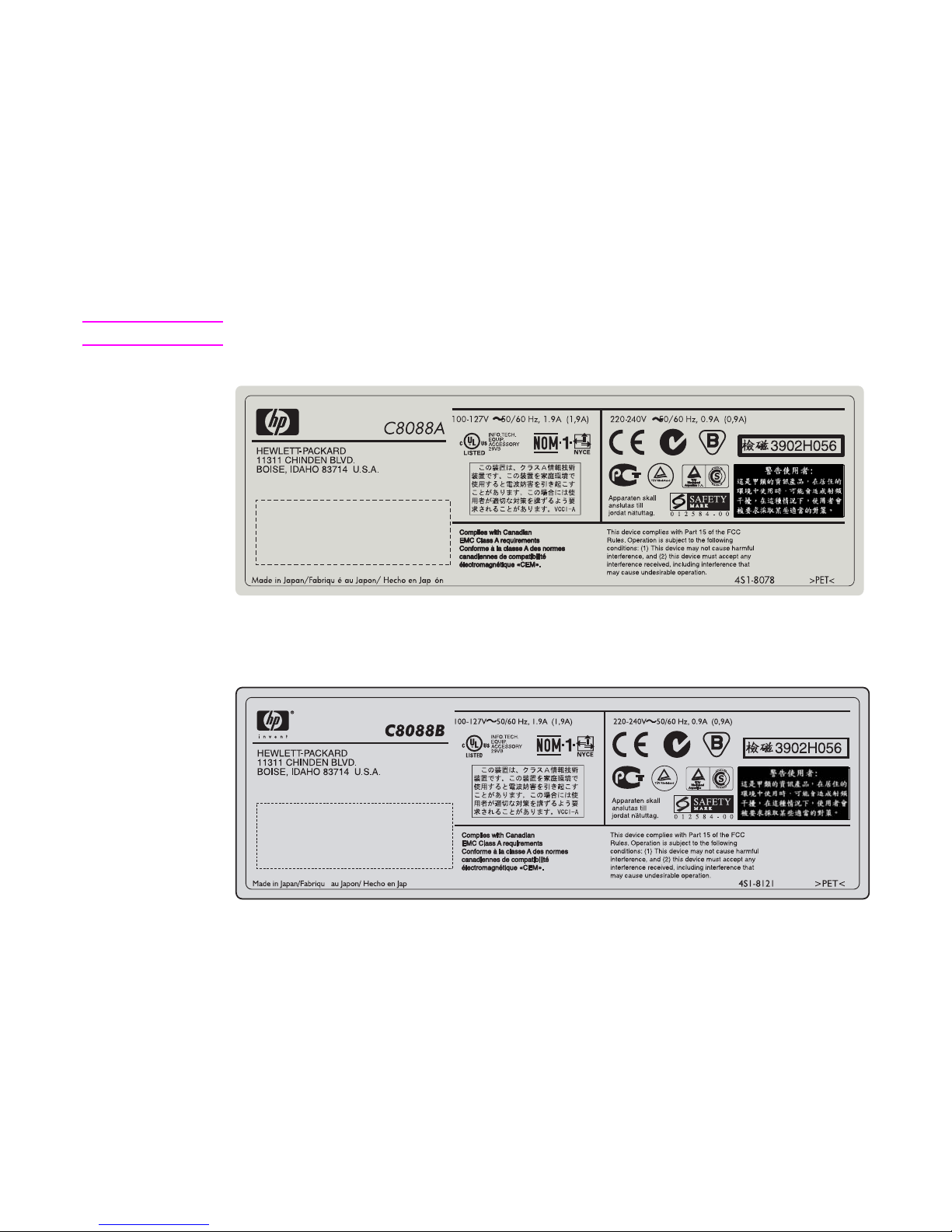
Multifunction finisher
The model number and serial number are listed on an identification label that is located on the
right side of the output device.
The serial number contains information about the country/region of origin, revision level,
production site, and manufacturing line, and the production number of the output device. An
example of a serial number is JPBGA12345.
The identification label also contains electrical information and regulat ory information. See
figure 1 or figure 2.
Note The electrical information and regulatory information vary by country/region.
Figure 1. Sample identification label—multifunction finisher (C8088A)
Figure 2. Sample identification label—multifunction finisher (C8088B)
é ón
Page 22

20 Product information ENWW
3,000-sheet stapler/stacker
The model number and serial number are listed on an identifi cation label that is located on the
back of the stapler/stacker.
The serial number contains information about the country/region of origin, revision level,
production site, and manufacturing line, and the production number of the output device. An
example of a serial number is MX04C04388.
The identification label also contains electrical information and regulatory information. See
figure 3.
Note The electrical information and regulatory information vary by country/region.
Figure 3. Sample identification labe l—3,000-sheet stapler/stacker
Page 23
ENWW Chapter 1 Product information 21
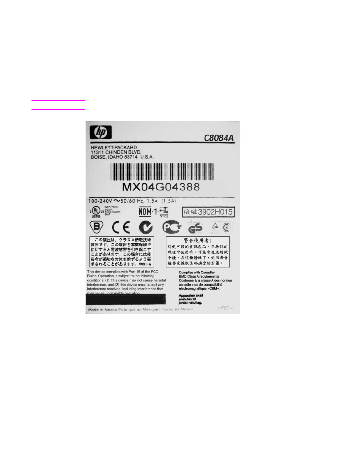
3,000-sheet stacker
The model number and serial number are listed on an identification label that is located on the
back of the stacker.
The serial number contains information about the country/region of origin, revision level,
production site, and manufacturing line, and the production number of the output device. An
example of a serial number is MX04G04388.
The identification label also contains electrical information and regulat ory information. See
figure 4.
Note The electrical information and regulatory information vary by country/region.
Figure 4. Sample identification label—3,000-sheet stacker
Page 24
22 Product information ENWW
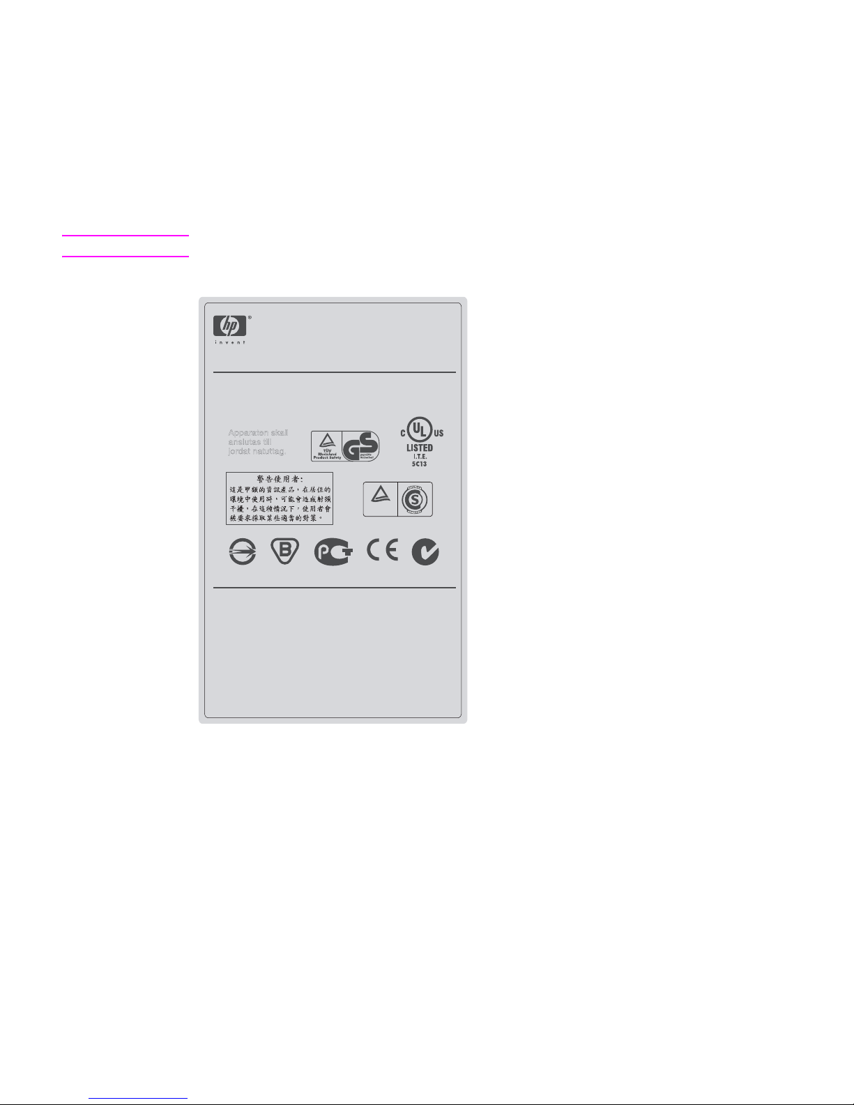
8-bin mailbox
The model number and serial number are listed on an identification label that is located on the
back of the 8-bin mailbox.
The serial number contains information about the country/region of origin, revision level,
production site, and manufacturing line, and the production number of the output device. An
example of a serial number is JPBGA12345.
The identification label also contains electrical information and regulatory information. See
figure 5.
Note The electrical information and regulatory information vary by country/region.
Figure 5. Sample identification label—8-bin mailbox
Hewlett-Packard Company
11311 CHINDEN BLVD.
BOISE, IDAHO 83714 U.S.A.
This device complies with Part 15 of the FCC Rules.
Operation is subject to the following conditions:
(1) This device may not cause harmful interference, and
(2) this device must accept any interference received,
including interference that may cause undesirable operation.
Complies with Canadian EMC Class A requirements Conforme
a la classe A des normes canadiennes de compatibilite
electromagnetique <<CEM>>
Apparaten skall
anslutas till
jordat natuttag.
D33001
Model Number:
Q5693A
Regulatory Model Number:
GUADA-0401-00
T.U.V
Rheinland
Ar gentina S.A
Product of Germany/Produit d'Allemagne
Page 25
ENWW Chapter 1 Product information 23
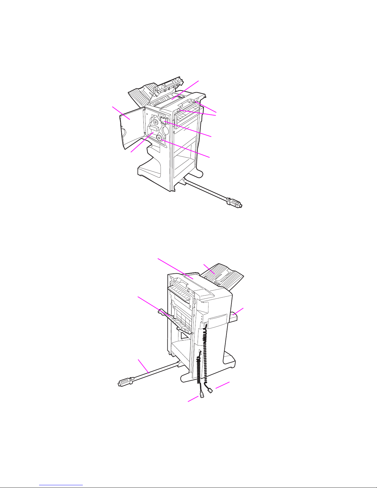
Product overview
Multifunction finisher
Figure 6. External assembly locations—multifunction finisher (front view)
Figure 7. External assembly locations—multifunction finisher (back view)
Processing-tray
Product-attachment
Product-release
upper cover
Jam-removal dial
Stapling unit
Stapler door
latch
handle
Booklet bin
(bin 2)
Stacker bin
(bin 1)
Jet-Link cable
Attachment-rod
Jam-removal cover
Top cover
assembly
Power cord
Page 26
24 Product information ENWW
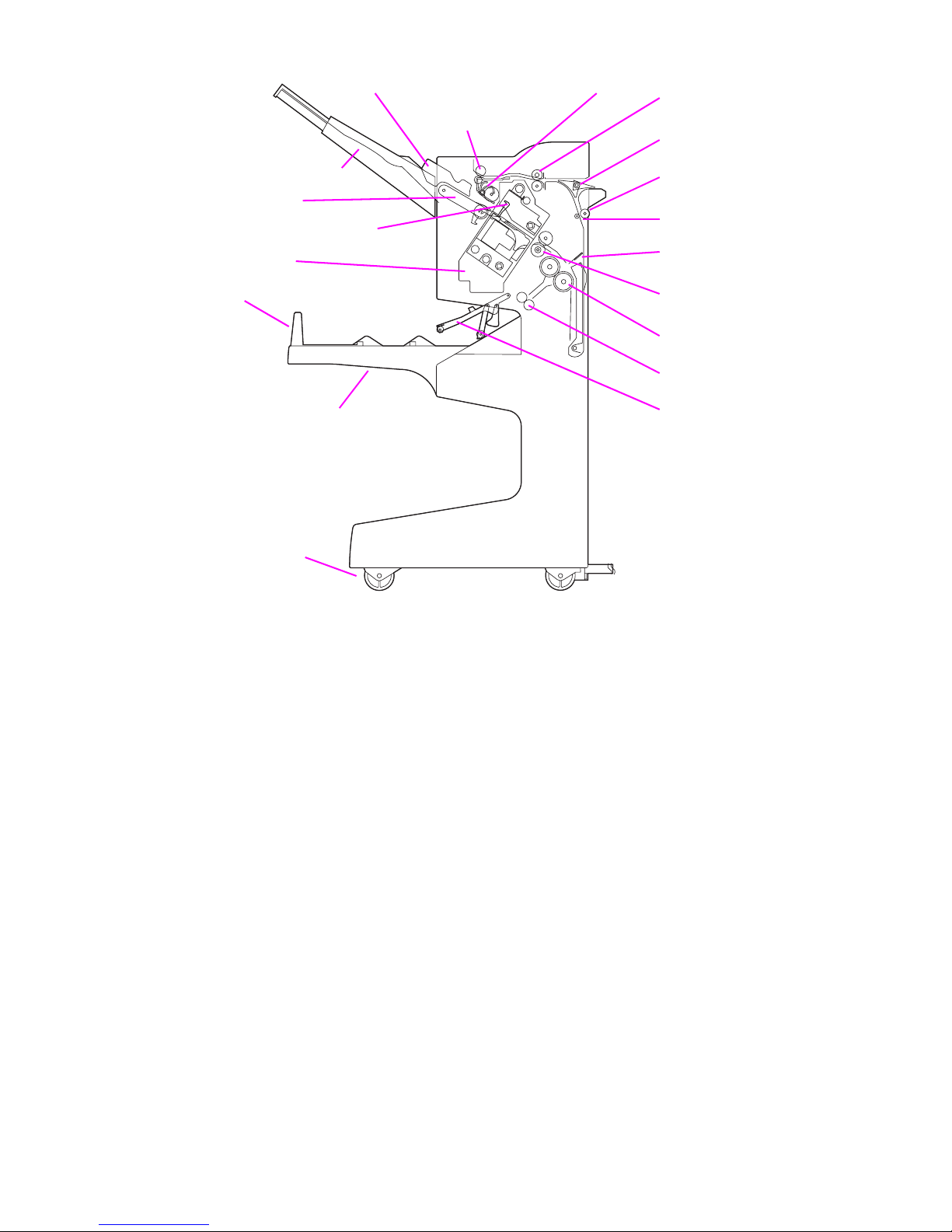
Figure 8. Cross-section—multifunction finisher
Processing tray stopper
Booklet bin stopper
Delivery roller
Stapling unit
Aligning plate (front and back)
Booklet bin (bin 2)
Stacker bin (bin 1)
Reversing flapper
Reversing roller
Paper-fold roller
Feed roller
Reversing nip roller
Paddle
Stack feed roller
Booklet-delivery roller
Paper-pushing plate
Delivery belt
Adjustable casters
Booklet-bin-full actuator
Page 27
ENWW Chapter 1 Product information 25
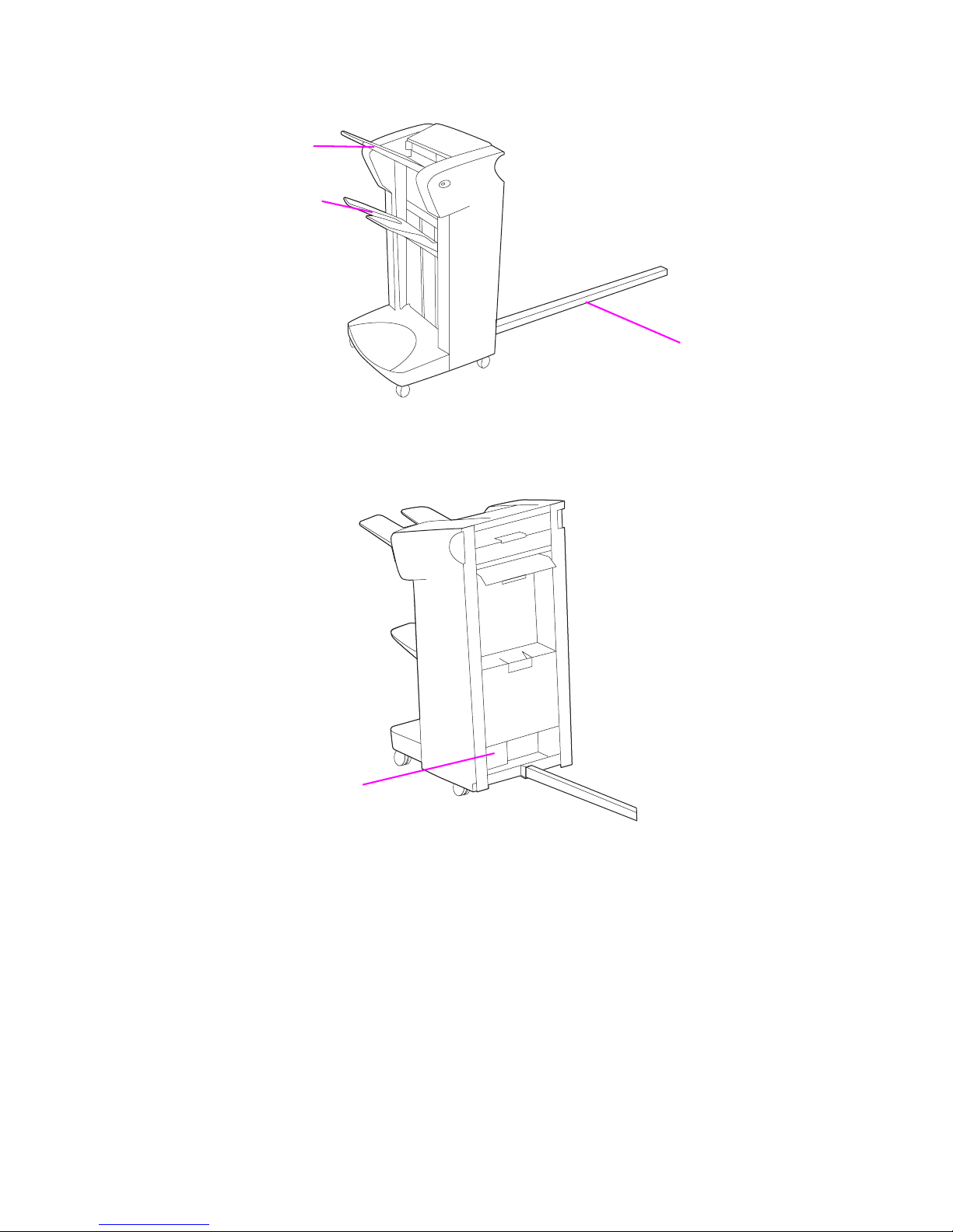
3,000-sheet stapler/stacker
Figure 9. External assembly locations—3,000-sheet stapler/stacker (front view)
Figure 10. External assembly locati ons—3,000-sheet stapler/stacker (back view)
Face-down or
Face-up bin
Attachment rod
stacker bin
Identification label
Page 28
26 Product information ENWW
Figure 11. Cross-section—3,000-sheet stapler/stacker
3,000-sheet stacker
Note The external assembly locations on the 3, 000-sheet stacker is t he same as that of the 3,000-sheet
stapler/stacker.
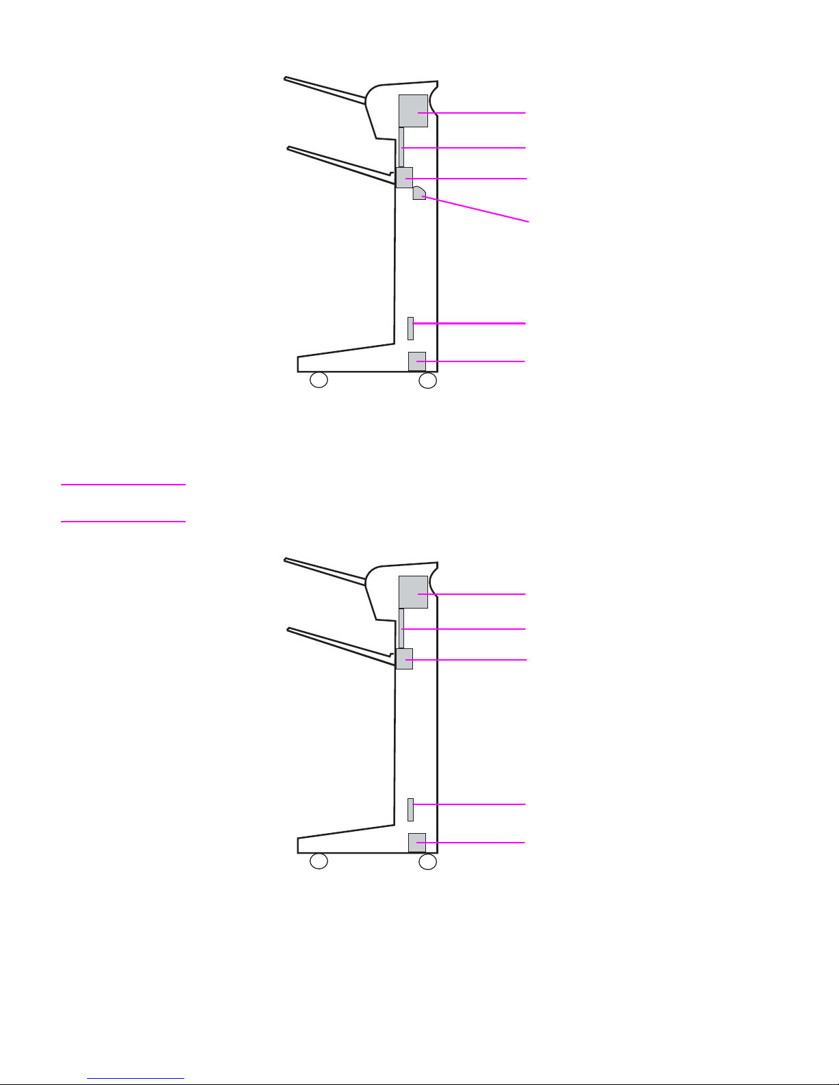
Figure 12. Cross-section—3,000-sheet stacker
Flipper
Paper path
Accumulator
Stapler cartridge
Controller PCA
Power supply
Flipper
Paper path
Offset module
Controller PCA
Power supply
Page 29
ENWW Chapter 1 Product information 27
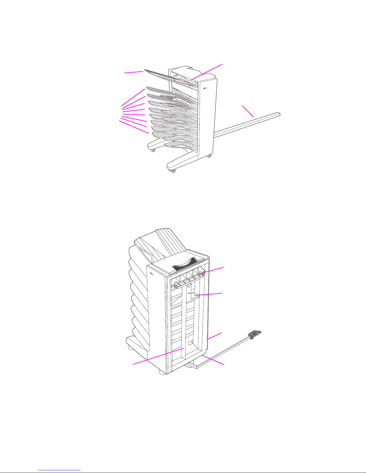
8-bin mailbox
Figure 13. External assembly locations—8-bin mailbox (left side view)
Figure 14. External assembly locations—8-bin mailbox (right side view)
Face-up bin
Face-down
bins
Attachment rod
Flipper
Input paper guide
Delivery head
Belt
Power
PCA
supply
Page 30

28 Product information ENWW
Specifications
Multifunction finisher
CAUTION Power requirements are based on the country/region where the output device is sold. Do not
convert operating v oltages. This can damage the output device and void the product warranty.
Note Testing per International Standards Organization (ISO) 9296.
Table 1. Physical specifications—multifunction finisher
Specification Multifunction finisher
Measurements Height: 985 mm (38.8 inches)
Width: 690 mm (27.2 inches)
Depth: 60 mm (23.6 inches)
Weight 44.4 kg (98 lb)
Table 2. Electrical specifications—multifu nction finisher
Volts Frequency
Amperes
(amps) Watts (W) (typical)
Thermal units per hour
(Btu/hr)
100-127 Vac
±10%
50/60 Hz
±2 Hz
Minimum
recommended
current capacity
= 13.0 amp
Printing = 1,075 W
Standby = 440 W
PowerSave 1 = 70 W
Low power = 230 W
Off = 0.5 W
ADF printing = 1,130 W
Printing = 3,670 Btu/hr
Standby = 1,500 Btu/hr
PowerSave 1 = 240 Btu/hr
Low power = 785 Btu/ hr
Off = 1.7 Btu/hr
ADF printing = 3,860 Btu/hr
220-240 Vac
±10%
50/60 Hz
±2 Hz
Minimum
recommended
current capacity
= 6.5 amp
Printing = 1,075 W
Standby = 440 W
PowerSave 1 = 70 W
Low power = 230 W
Off = 1.3 W
ADF printing = 1,130 W
Printing = 3,650 Btu/hr
Standby = 1,420 Btu/hr
PowerSave 1 = 240 Btu/hr
Low power= 785 Btu/hr
Off = 4.5 Btu/hr
ADF printing = 3,670 Btu/hr
Table 3. Environmental specifications—multifunction finisher
Condition Operating/printing Storage/standby
Temperature
(multifunction finisher
and print cartridge)
10° to 33°C
(50° to 91°F)
0° to 35°C
(32° to 95°F)
Relative humidity 10% to 80% 15% to 90%
Table 4. Acoustic emissions specifications—multifunction finisher
Condition Operator position Bystander (1 m) Sound power
Copying at 50 ppm L
Pam
57 db(A) L
Pam
60 db(A) L
WAd
7.3 bels(A)
Idle L
Pam
40 db(A) L
Pam
40 db(A) L
WAd
5.4 bels(A)
PowerSave inaudible inaudible inaudible
Page 31

ENWW Chapter 1 Product information 29
3,000-sheet stapler/stacker
CAUTION Power requirements are based on the country/region where the output device is sold. Do not
convert operating voltages. This can damage the output device and void the product warranty.
Note Testing per International Standa rd s Or ga niz at i on (ISO ) 92 96 .
Table 5. Physical specifications—3,000-sheet stapler/stacker
Specification HP 3,000-sheet stapler/stacker
Measurements Height: 1,004 mm (39.5 inches)
Width: 555 mm (21.8 inches)
Depth: 536 mm (21.1 inches)
Weight 32 kg (70.5 lb)
Table 6. Electrical specifications—3,000-sheet stapler/stacker
Volts Frequency
Amperes
(amps) Watts (W) (typical)
Thermal units per hour
(Btu/hr)
100-127 Vac
±10%
50/60 Hz
±2 Hz
Minimum
recommended
current capacity
= 13.0 amp
Printing = 1,075 W
Standby = 440 W
Po werSave 1 = 70 W
Low power = 230 W
Off = 0.5 W
ADF printing = 1,130 W
Printing = 3,670 Btu/hr
Standby = 1,500 Btu/hr
Po werSave 1 = 240 Btu/hr
Low power = 785 Btu/hr
Off = 1.7 Btu/hr
ADF printing = 3,860 Btu/hr
220-240 Vac
±10%
50/60 Hz
±2 Hz
Minimum
recommended
current capacity
= 6.5 amp
Printing = 1,075 W
Standby = 440 W
Po werSave 1 = 70 W
Low power = 230 W
Off = 1.3 W
ADF printing = 1,130 W
Printing = 3,650 Btu/hr
Standby = 1,420 Btu/hr
Po werSave 1 = 240 Btu/hr
Low power= 785 Btu/hr
Off = 4.5 Btu/hr
ADF printing = 3,670 Btu/hr
Table 7. Environmental specifications—3,000-sheet stapler/stacker
Condition Operating/printing Storage/standby
Temperature
(output devices and
print cartridge)
10° to 33°C
(50° to 91°F)
0° to 35°C
(32° to 95°F)
Relative humidity 10% to 80% 15% to 90%
Table 8. Acoustic emissions specifications—3,000-sheet stapler/stacker
Condition Operator position Bystander (1 m) Sound power
Copying at 50 ppm L
Pam
57 db(A) L
Pam
60 db(A) L
WAd
7.3 bels(A)
Idle L
Pam
40 db(A) L
Pam
40 db(A) L
WAd
5.4 bels(A)
PowerSave inaudible inaudible inaudible
Page 32

30 Product information ENWW
3,000-sheet stacker
CAUTION Power requirements are based on the country/region where the output device is sold. Do not
convert operating v oltages. This can damage the output device and void the product warranty.
Note Testing per International Standards Organization (ISO) 9296.
Table 9. Physical specifications—3,000-sheet stacker
Specification HP 3,000-sheet stacker
Measurements Height: 1,004 mm (39.5 inches)
Width: 555 mm (21.8 inches)
Depth: 536 mm (21.1 inches)
Weight 32 kg (70.5 lb)
Table 10. Electrical specifications—3,000-sheet stacker
Volts Frequency
Amperes
(amps) Watts (W) (typical)
Thermal units per hour
(Btu/hr)
100-127 Vac
±10%
50/60 Hz
±2 Hz
Minimum
recommended
current capacity
= 13.0 amp
Printing = 1,075 W
Standby = 440 W
PowerSave 1 = 70 W
Low power = 230 W
Off = 0.5 W
ADF printing = 1,130 W
Printing = 3,670 Btu/hr
Standby = 1,500 Btu/hr
PowerSave 1 = 240 Btu/hr
Low power = 785 Btu/ hr
Off = 1.7 Btu/hr
ADF printing = 3,860 Btu/hr
220-240 Vac
±10%
50/60 Hz
±2 Hz
Minimum
recommended
current capacity
= 6.5 amp
Printing = 1,075 W
Standby = 440 W
PowerSave 1 = 70 W
Low power = 230 W
Off = 1.3 W
ADF printing = 1,130 W
Printing = 3,650 Btu/hr
Standby = 1,420 Btu/hr
PowerSave 1 = 240 Btu/hr
Low power= 785 Btu/hr
Off = 4.5 Btu/hr
ADF printing = 3,670 Btu/hr
Table 11. Environmental specifications—3,000-sheet stacker
Condition Operating/printing Storage/standby
Temperature
(output devices and
print cartridge)
10° to 33°C
(50° to 91°F)
0° to 35°C
(32° to 95°F)
Relative humidity 10% to 80% 15% to 90%
Table 12. Acoustic emissions specifications—3,000-sheet stacker
Condition Operator position Bystander (1 m) Sound power
Copying at 50 ppm L
Pam
57 db(A) L
Pam
60 db(A) L
WAd
7.3 bels(A)
Idle L
Pam
40 db(A) L
Pam
40 db(A) L
WAd
5.4 bels(A)
PowerSave inaudible inaudible inaudible
Page 33

ENWW Chapter 1 Product information 31
8-bin mailbox
Table 13. Physical specifications—8-bin mailbox
Specification 8-bin mailbox
Measurements Height: 970 mm (38.2 inches)
Width: 435 mm (17.1 inches)
Depth: 480 mm (18.9 inches)
Weight 19.2 kg (51.4 lb)
Table 14. Power requirements and circuit capaci ty—8-bin mailbox
Requirement or
capacity
110-volt models 220-volt models
Power requirements 110 to 127 volts (V)
(+/- 10%)
50 to 60 hertz (Hz)
(+/- 2 Hz)
220 V (+/- 10%)
50 to 60 Hz (+/- 2 Hz)
-Or220 to 240 V (+/- 10%)
60 Hz (+/- 2 Hz)
Minimum
recommended circuit
capacity
15.0 amps 6.5 amps
Table 15. Power consumption—8-bin mailbox
Printer state 100 to 127-volt
models
220 to 240-volt
models
Printing 34.3 watts 32.6 watts
Standby 11 watts 10.3 watts
PowerSave 0.1 watt 0.6 watt
Table 16. Operating and storage environment—8-bin mailbox
Variable Allowable condition
Operating temperature 10° to 32.5° C (50° to 95°F)
Operating humidity 20% to 80%
Storage temperature 0° to 45°C (32° to 113°F)
Storage humidity 20% to 80%
Page 34

32 Product information ENWW
Regulatory information
Declaration of Conformity—multifunction finisher
Declaration of Conformity
according to ISO/IEC Guide 22 and CEN/CENELEC EN 45014
Manufacturer's Name: Hewlett-Packard Company
Manufacturer's Address: Montemorelos 299
Guadalajara Jalisco, 45060, Mexico
declares, that the product
Product Name: HP Multifunction Finisher
Model Number: C8088A, C8088B
Product Options: N/A
conforms to the following Product Specifications:
Safety: IEC 950:1991+A1+A2+A3+A4 / EN 60950:1992+A1+A2+A3+A4+A11
IEC 825-1:1993/EN 60825-1:1994 Class 1 (Laser/LED)
UL 1950, Third Edition
EMC: CISPR 22:1997 / EN 55022:1998 Class B
1
EN 55024:1998
EN 61000-3-2:1995/EN 61000-3-2: 1995
EN 61000-3-3:1994/EN 61000-3-3: 1995
FCC Title 47 CFR, Part 15 Class B
2
/ ICES-003, Issue 3
AS / NZS 3548:1992/CISPR 22: 1993 Class B
1
Supplementary Information:
The product herewith complies with the requirements of the EMC Directive 89/336/EEC and the Low
Voltage Directive 73/23/EEC, and carries the CE-marking accordingly.
1) The product was tested in a typical configuration with Hewlett-Packard Personal Computer
Systems.
2) This Device complies with Part 15 of the FCC Rules. Operation is subject to the following two
Conditions:
(1) this device may not cause harmful interference, and
(2) this device must accept any interference received, including interference
that may cause undesired operation.
Hewlett-Packard Company
Guadalajara, Jalisco, MEXICO
8 May, 2001
For regulatory topics only:
Australia Contact: Product Regulations Manager, Hewlett-Packard Australia Ltd., 31-41 Joseph
Street, Blackburn, Victoria 3130, Australia
European Contact: Your Local Hewlett-Packard Sales and Service Office or Hewlett-Packard
GmbH, Department HQ-TRE / Standards Europe, Herrenberger Straße 130,
D-71034 Böblingen (FAX: +49-7031-14-3143)
USA Contact: Product Regulations Manager, Hewlett-Packard Company, POBox 15, Mail
Stop 160, Boise, ID 83707-0015 (Phone: 208-396-6000)
Page 35

ENWW Chapter 1 Product information 33
Declaration of Conf ormity—3,000-sheet stapler/stacker
Declaration of Conformity
according to ISO/IEC Guide 22 and CEN/CENELEC EN 45014
Manufacturer's Name: Hewlett-Packard Company
Manufacturer's Address: Montemorelos 299
Guadalajara Jalisco, 45060, Mexico
declares, that the product
Product Name: 3,000-sheet Stapler/Stacker
Model Number: C8085A
Product Options: N/A
conforms to the following Product Specifications:
Safety: IEC 950:1991+A1+A2+A3+A4 / EN 60950:1992+A1+A2+A3+A4+A11
IEC 825-1:1993/EN 60825-1:1994 Class 1 (Laser/LED)
UL 1950, Third Edition
EMC: CISPR 22:1997 / EN 55022:1998 Class B
1
EN 55024:1998
EN 61000-3-2:1995/EN 61000-3-2: 1995
EN 61000-3-3:1994/EN 61000-3-3: 1995
FCC Title 47 CFR, Part 15 Class B
2
/ ICES-003, Issue 3
AS / NZS 3548:1992/CISPR 22: 1993 Class B
1
Supplementary Information:
The product herewith complies with the requirements of the EMC Directive 89/336/EEC and the Low
Voltage Directive 73/23/EEC, and carries the CE-marking accordingly.
1) The product was tested in a typical configuration with Hewlett-Packard Personal Computer
Systems.
2) This Device complies with Part 15 of the FCC Rules. Operation is subject to the following two
Conditions:
(1) this device may not cause harmful interference, and
(2) this device must accept any interference received, including interference
that may cause undesired operation.
Hewlett-Packard Company
Guadalajara, Jalisco, MEXICO
8 May, 2001
For regulatory topics only:
Australia Contact: Product Regulations Manager, Hewlett-Packard Australia Ltd., 31-41 Joseph
Street, Blackburn, Victoria 3130, Australia
European Contact: Your Local Hewlett-Packard Sales and Service Office or Hewlett-Packard
GmbH, Department HQ-TRE / Standards Europe, Herrenberger Straße 130,
D-71034 Böblingen (FAX: +49-7031-14-3143)
USA Contact: Product Regulations Manager, Hewlett-Packard Company, PO Box 15, Mail
Stop 160, Boise, ID 83707-0015 (Phone: 208-396-6000)
Page 36

34 Product information ENWW
Declaration of Conformity—3,000-sheet stacker
Declaration of Conformity
according to ISO/IEC Guide 22 and CEN/CENELEC EN 45014
Manufacturer's Name: Hewlett-Packard Company
Manufacturer's Address: Montemorelos 299
Guadalajara Jalisco, 45060, Mexico
declares, that the product
Product Name: 3,000-sheet Stacker
Model Number: C8084A
Product Options: N/A
conforms to the following Product Specifications:
Safety: IEC 950:1991+A1+A2+A3+A4 / EN 60950:1992+A1+A2+A3+A4+A11
IEC 825-1:1993/EN 60825-1:1994 Class 1 (Laser/LED)
UL 1950, Third Edition
EMC: CISPR 22:1997 / EN 55022:1998 Class B
1
EN 55024:1998
EN 61000-3-2:1995/EN 61000-3-2: 1995
EN 61000-3-3:1994/EN 61000-3-3: 1995
FCC Title 47 CFR, Part 15 Class B
2
/ ICES-003, Issue 3
AS / NZS 3548:1992/CISPR 22: 1993 Class B
1
Supplementary Information:
The product herewith complies with the requirements of the EMC Directive 89/336/EEC and the Low
Voltage Directive 73/23/EEC, and carries the CE-marking accordingly.
1) The product was tested in a typical configuration with Hewlett-Packard Personal Computer
Systems.
2) This Device complies with Part 15 of the FCC Rules. Operation is subject to the following two
Conditions:
(1) this device may not cause harmful interference, and
(2) this device must accept any interference received, including interference
that may cause undesired operation.
Hewlett-Packard Company
Guadalajara, Jalisco, MEXICO
8 May, 2001
For regulatory topics only:
Australia Contact: Product Regulations Manager, Hewlett-Packard Australia Ltd., 31-41 Joseph
Street, Blackburn, Victoria 3130, Australia
European Contact: Your Local Hewlett-Packard Sales and Service Office or Hewlett-Packard
GmbH, Department HQ-TRE / Standards Europe, Herrenberger Straße 130,
D-71034 Böblingen (FAX: +49-7031-14-3143)
USA Contact: Product Regulations Manager, Hewlett-Packard Company, POBox 15, Mail
Stop 160, Boise, ID 83707-0015 (Phone: 208-396-6000)
Page 37

ENWW Chapter 1 Product information 35
Declaration of Conformity—8-bin mailbox
Declaration of Conformity
According to ISO/IEC Guide 22 and CEN/CENELEC EN 45014
Manufacturer’s Name: Hewlett-Packard Company
Manufacturer’s Address: Montemorelos 299
Guadalajara Jalisco, 45060
Mexico
Declares, that the product
Product Name: HP 8-bin Mailbox
Model Numbers: Q5693A, Q5710A
Regulatory Model: GUADA-0401-00
Product Options: All
Is in conformity with:
SAFETY: IEC 60950:1999 / EN60950:2000
EMC: CISPR 22:1997 / EN55022:1998 Class A
1
CISPR 24:1997 / EN 55024:1998
IEC 61000-3-2:2000 / EN61000-3-2:2000
IEC 61000-3-3:1994 +A1 / EN61000-3-3:1995 +A1
FCC Title 47 CFR, Part 15 Class A
/ ICES-003, Issue 4
Supplementary Information:
The product herewith complies with the requirements of the EMC Directive 89/336/EEC and the Low
Voltage Directive 73/23/EEC, and carries the CE-Marking accordingly.
1) The product was tested in a typical configuration with Hewlett-Packard Personal Computer Systems.
2) This Device complies with Part 15 of the FCC Rules. Operation is subject to the following two
Conditions:
(1) this device may not cause harmful interference, and
(2) this device must accept any interference received, including interference that may cause
undesired operation.
For Regulatory Topics Only:
Australia Contact: Product Regulations Manager, Hewlett-Packard Australia Ltd., 31-41
Joseph Street, Blackburn, Victoria 3130, Australia
European Contact: Your Local Hewlett-Packard Sales and Service Office or Hewlett-Packard
Gmbh, Department HQ-TRE / Standards Europe, Herrenberger Straße
140, D-71034 Böblingen (FAX: +49-7031-14-3143)
USA Contact: Product Regulations Manager, Hewlett-Packard Company, PO Box 15,
Mail Stop 160, Boise, Idaho 83707-0015 (Phone: 208-396-6000)
Page 38

36 Product information ENWW
Service approach
Repair of the output device no rmally begins with a three-step process:
1 Isolate the problem to the major system (the host computer, the network or server, or the
finishing-device system).
2 Determine whether the problem is located in the output device, the print unit, or the copy/
scan unit.
3 Troubleshoot the problem by using the “Troubleshooting flowchart” on page 198.
Repair is usually accomplished by an assembly-level replacement of field replaceable units
(FRUs). Some mechanical assemblies can be repaired at the subassembly level. HewlettPackard does not support replacement of components on the printed circuit assemblies.
Parts and supplies
“Consumables and documentation” on page 252 contains FRU and replacement part numbers,
and contains information about products that are specifically designed for the output device.
Replacement parts can be ordered from the HP Customer Support (HPCS) organization.
Exchange program
Hewlett-Packard might offer remanufactured assemblies for parts. These can be ordered
through HPCS.
Warranty
For warranty information and requirements, see the user guide f or the printer.
Page 39

ENWW Chapter 2 Installation 37
2 Installation
Chapter contents
Environmental requirements . . . . . . . . . . . . . . . . . . . . . . . . . . . . . . . . . . . . . . . . . . . . 38
Physical requirements . . . . . . . . . . . . . . . . . . . . . . . . . . . . . . . . . . . . . . . . . . . . . . . . . 39
Multifunction finisher . . . . . . . . . . . . . . . . . . . . . . . . . . . . . . . . . . . . . . . . . . . . 39
3,000-sheet stapler/stacker and 3,000-sheet stacker . . . . . . . . . . . . . . . . . . . 40
8-bin mailbox. . . . . . . . . . . . . . . . . . . . . . . . . . . . . . . . . . . . . . . . . . . . . . . . . . 41
Page 40

38 Installation ENWW
Environmental requirements
The electrical and environmental specifications must be maintained to ens ure th e cor re ct
operation of the output device. Consider the following points before installing the output device:
● Install in a well-ventilated, dust-free area.
● Install on a level, flat surface that can support the printer and output device size and weight.
● Ensure adequate power-supply circuitry (see table 2 on page 28).
● Install where temperature and humidity are stable, with no abrupt changes, and away from
water sources, heating vents, humidifiers, air conditioners , refrigerators, or other major
appliances (see table 3 on page 28).
● Install away from direct sunlight, areas that experience vibration, open flames, ammonia
fumes, ultrasonic heaters, and devices that emit a magnetic field. If the output device is
placed near a window, make sure the window has a curtain or blind to block direct sunlight.
● Maintain enough space around the output device for proper access and ventilation (see
“Physical requirements” on page 39).
Page 41

ENWW Chapter 2 Installation 39
Physical requirements
Multifunction finisher
Prepare a location for the out put device. The space must accommodate the physical and
environmental requirements contained in this section, in addition to the requirements for the
printer.
Figure 15. Multifunction finisher (side view and top view)
690 mm
(27.2 inches)
904 mm (35.6 inches)
985 mm (38.8 inches)
600 mm (23.6 inches)
520 mm
(20.5 inches)
Page 42

40 Installation ENWW
3,000-sheet stapler/stacker and 3,000-sheet stacker
Note Dimensions of the 3,000-sheet stapler/stacker and the 3,000-sheet stacker are identical.
Figure 16. 3,000-sheet stapler/stacker (side view and top view)
555 mm
21.8 inches
520 mm
(20.5 inches)
1,004 mm (39.5 inches)
536 mm (21.1 inches)
Page 43

ENWW Chapter 2 Installation 41
8-bin mailbox
Figure 17. 8-bin mailbox (top view and side view)
480 mm
(18.9 in)
435 mm
(17.1 in)
630 mm
(24.8 in)
918 mm
(36.1 in)
970 mm
(38.2 in)
Page 44

42 Installation ENWW
Page 45

ENWW 3 Operation 43
3 Operation
Chapter contents
Supported media . . . . . . . . . . . . . . . . . . . . . . . . . . . . . . . . . . . . . . . . . . . . . . . . . . . . . 44
Multifunction finisher . . . . . . . . . . . . . . . . . . . . . . . . . . . . . . . . . . . . . . . . . . . . 44
3,000-sheet stapler/stacker. . . . . . . . . . . . . . . . . . . . . . . . . . . . . . . . . . . . . . . 46
3,000-sheet stacker. . . . . . . . . . . . . . . . . . . . . . . . . . . . . . . . . . . . . . . . . . . . . 46
8-bin mailbox. . . . . . . . . . . . . . . . . . . . . . . . . . . . . . . . . . . . . . . . . . . . . . . . . . 47
Using media. . . . . . . . . . . . . . . . . . . . . . . . . . . . . . . . . . . . . . . . . . . . . . . . . . . . . . . . . 48
Multifunction finisher . . . . . . . . . . . . . . . . . . . . . . . . . . . . . . . . . . . . . . . . . . . . 48
3,000-sheet stapler/stacker. . . . . . . . . . . . . . . . . . . . . . . . . . . . . . . . . . . . . . . 50
Page 46

44 Operation ENWW
Supported media
Multifunction finisher
Output bin Capacity Media Feeding
orientation¹
Weight
Stacker bin (bin 1)
capacity, face-up
Up to 1,000 sheets of 75 g/m2 (20 lb)
bond, stacked, of letter/A4
Up to 500 sheets of 75 g/m
2
(20 lb) bond,
stacked, of legal/B4 or ledger/A3
Letter, ISO A4
● P or L 64 to 216 g/m
2
(17 to 58 lb)
Legal, ledger,
executive, ISO A3, ISO
A5, JIS B4, JIS B5
● P
Custom sizes:
Minimum: 98 x 191 mm
(3.9 x 7.5 inches)
Maximum: 312 x 470
mm (12.2 x 18.4
inches)
● P or L when
longer edge is
312 mm or less
● P when longer
edge is greater
than 312 mm
Envelopes (Monarch,
DL, B5, C5)
Note
A bin-full is indicated
when a job using
envelopes is sent.
The maximum number
of envelopes that can
be stacked is 1 0.
● P
Labels (letter or A4),
transparencies (letter or
A4)
● P or L
Stacker bin (bin 1)
capacity, face-down
Up to 1,000 sheets of 75 g/m
2
(20 lb)
bond, stacked, of letter/A4
Up to 500 sheets of 75 g/m
2
(20 lb) bond,
stacked, of legal/B4 or ledger/A3
Letter, ISO A4
● P or L 64 to 199 g/m
2
(17 to 53 lb)
Legal, ledger,
executive, ISO A3, ISO
A5, JIS B4, JIS B5
● P
Transparencies (letter
or A4)
● P or L
Stapling capacity of
stacker bin (bin 1) or
booklet bin (bin 2) per
job
Maximum of 50 sheets of letter/A4
Maximum of 25 sheets of ledger/A3
Letter, ISO A4 ● P or L 64 to 199 g/m2
(17 to 53 lb)
Legal, ledger, ISO A3,
JIS B4
● P
NOTE: The stacker bin is full at a 34-mm stack height, or not more than 30 jobs.
See “Approximate number of sheets that can be stapled, listed by media weight” on
page 48.
Page 47

ENWW 3 Operation 45
¹P = Portrait (short-edge first)
L = Landscape (long-edge first)
Booklet bin (bin 2)
capacity
Up to 40 booklets composed of 5 sheets
(see “Number of sheets that can be
stapled and folded, listed by booklet size”
on page 48).
Letter, legal, ledger,
ISO A4, ISO A3, JIS B4
● P 64 to 199 g/m
2
(17 to 53 lb)
See “Number of sheets that can be stapled and folded, listed by media weight” on page 48.
Also see “Number of sheets that can be stapled and folded, listed by booklet size” on page 48.
Output bin Capacity Media Feeding
orientation¹
Weight
Page 48

46 Operation ENWW
3,000-sheet stapler/stacker
3,000-sheet stacker
Function Capacity Media Weight
Bin 1 (face-up
bin)
Up to 125 sheets of letter/
A4
● Letter, legal, executive, ISO A3,
ISO A4, ISO A5, 11 x 17, JIS B5,
JIS B4, JPostD, Monarch, 8K,
16K
● Custom sizes
● Custom types: envelopes, labels,
transparencies, heavy paper
64 to 216 g/m2 (17 to
58 lb bond)
Bin 2 (face-dow n
bin)
Up to 3,000 sheets
stacked (up to 50 sheets
stapled) of letter/A4
Up to 1,500 sheets of
ledger or A3
● Letter, legal, executive, ISO A3,
ISO A4, ISO A5, 11 x 17, JIS B5,
JIS B4, 8K, 16K
64 to 199 g/m2 (17 to
53 lb bond)
Function Capacity Media Weight
Bin 1 (face-up
bin)
Up to 125 sheets of letter/
A4
● Letter, legal, executive, ISO A3,
ISO A4, ISO A5, 11 x 17, JIS B5,
JIS B4, JPostD, Monarch, 8K,
16K
● Custom sizes
● Custom types: envelopes, labels,
transparencies, heavy paper
64 to 216 g/m
2
(17 to
58 lb bond)
Bin 2 (face-dow n
bin)
Up to 3,000 sheets
stacked (up to 50 sheets
stapled) of letter or A4
Up to 1,500 sheets of
ledger/A3
● Letter, legal, executive, ISO A3,
ISO A4, ISO A5, 11 x 17, JIS B5,
JIS B4, 8K, 16K
64 to 199 g/m2 (17 to
53 lb bond)
Page 49

ENWW 3 Operation 47
8-bin mailbox
1 - Letterhead with raised lettering or low-temperature inks is not supported.
Output bin Capacity Media size Media Weight
Face-down bins Up to 250
sheets
● Standard sizes:
letter, legal, ISO A3, ISO A4,
ISO A5, 11 x 17, JIS B4, JIS
B5, 8k, 16k
● Custom sizes:
minimum: 148 x 210 mm
(5.83 x 8.27 inches)
maximum: 297 x 432 mm
(11.69 x 17 inches)
● plain
● preprinted
● letterhead
1
● prepunched
● bond
● color
● recycled
● light
● glossy
● heavy
● rough
● heavy glossy
● non-HP
heavy glossy
● high-gloss
images
64 to 135 g/m
2
(17 to 36-lb bond)
Face-up bin Up to 125
sheets
● Standard sizes:
letter, legal, executive, ISO
A3, ISO A4, ISO A5, 11 x 17,
JIS B4, JIS B5, jpostD, 8k,
16k
● Custom sizes:
minimum: 98 x 170 mm (3.86
x 6.7 inches)
maximum: 305 x 470 mm (12
x 18.5 inches)
● plain
● preprinted
● letterhead
1
● prepunched
● bond
● color
● recycled
● light
● glossy
● heavy
● rough
● heavy glossy
● non-HP
heavy glossy
● high-gloss
images
● tough paper
● labels
● envelopes
● cardstock
● transparencies
64 to 216 g/m
2
(14 to 58-lb bond)
Page 50

48 Operation ENWW
Using media
Multifunction finisher
Note Up to nine sheets of coated media can be stapled.
Note When making booklets with media that weighs 64 g/m2 (17 lb) to 80 g/m2 (21 lb), one cov er sheet
up to 199 g/m
2
(53 lb) in weight can be combined with the 10 sheets. Othe r combinations are not
supported.
Note The numbers might vary depending on the operating conditions.
Table 17. Approximate number of sheets that can be stapled, listed by media weight
Media weight Letter/A4 Ledger/A3 and legal/B4
64 g/m2 (17 lb) 50 25
75 g/m
2
(20 lb) 50 25
80 g/m
2
(21 lb) 50 25
90 g/m
2
(24 lb) 44 22
105 g/m
2
(28 lb) 28 14
163 g/m
2
(43 lb) 18 9
199 g/m
2
(53 lb) 12 6
Table 18. Number of sheets that can be stapled and folded, listed by media weight
Media weight Letter/A4, ledger/A3 and legal/B4
64 g/m2 (17 lb) to 80 g/m2 (21 lb) Maximum of 10 sheets
90 g/m
2
(24 lb) to 105 g/m2 (28 lb) Maximum of 5 sheets
163 g/m
2
(43 lb) to 199g/m2 (53 lb) Maximum of 1 sheet (will not be stapled)
Table 19. Number of sheets that can be stapled and folded, listed by booklet size
Approximate number of booklets until
bin-full
Booklet type
Letter/A4 Ledger/A3
1 cover sheet of 199 g/m2 (53 lb) media plus 4 sheets of
75 g/m
2
(20 lb) media
40 30
2 sheets of 75 g/m
2
(20 lb) media 52 52
5 sheets of 75 g/m
2
(20 lb) media 48 40
10 sheets of 75 g/m
2
(20 lb) media 24 20
Page 51

ENWW 3 Operation 49
Table 20. Skew specifications—multifunction finisher
Skew type Specification Diagram
Folding X = +/- 2.5 mm (0.10 inch),
specified at center
Y = +/- 2.5 mm (0.10 inch),
length
NOTE: The measurement is affected by expansion or shrinkage of the sheet as a
result of fusing. The amount of expansion or shrinkage depends on the type of
media. Some media can expand or shrink by 2 mm (0.08 inch).
Stapling X = +/- 1.0 mm (0.04 inch)
NOTE: Take this measurement on the inside sheet of an open booklet.
X
Y
Feeding
direction
Stapling line
X
Folding line
Page 52

50 Operation ENWW
3,000-sheet stapler/stacker
Table 21. Approximate number of sheets that can be stapled, listed by media weight
Media weight Letter/A4 Ledger/A3 and legal/B4
64 g/m2 (17 lb) 50 50
75 g/m
2
(20 lb) 50 50
80 g/m
2
(21 lb) 50 50
90 g/m
2
(24 lb) 45 45
105 g/m
2
(28 lb) 35 35
163 g/m
2
(43 lb) 30 30
199 g/m
2
(53 lb) 25 25
Page 53

ENWW 4 Maintenance 51
4 Maintenance
Chapter contents
Cleaning the outside of the product . . . . . . . . . . . . . . . . . . . . . . . . . . . . . . . . . . . . . . . 52
Cleaning inside the product . . . . . . . . . . . . . . . . . . . . . . . . . . . . . . . . . . . . . . . . . . . . . 52
Page 54

52 Maintenance ENWW
Cleaning the outside of the product
When outside covers and panels are noticeably dirty, wipe them with a dampened cloth.
Cleaning inside the product
Over time, dust can accumula te inside the output de vice. Remo ving the dust is not a requirement
for smooth operation of the products. However, dust can be removed by using a dry cloth or a
handheld vacuum cleaner.
Page 55

ENWW Chapter 5 Theory of operation 53
5 Theory of operation
Chapter contents
Power-on sequence . . . . . . . . . . . . . . . . . . . . . . . . . . . . . . . . . . . . . . . . . . . . . . . . . . . 54
Multifunction finisher . . . . . . . . . . . . . . . . . . . . . . . . . . . . . . . . . . . . . . . . . . . . 54
3,000-sheet stapler/stacker. . . . . . . . . . . . . . . . . . . . . . . . . . . . . . . . . . . . . . . 54
3,000-sheet stacker. . . . . . . . . . . . . . . . . . . . . . . . . . . . . . . . . . . . . . . . . . . . . 54
8-bin mailbox. . . . . . . . . . . . . . . . . . . . . . . . . . . . . . . . . . . . . . . . . . . . . . . . . . 55
Basic operation . . . . . . . . . . . . . . . . . . . . . . . . . . . . . . . . . . . . . . . . . . . . . . . . . . . . . . 56
Multifunction finisher . . . . . . . . . . . . . . . . . . . . . . . . . . . . . . . . . . . . . . . . . . . . 56
3,000-sheet stapler/stacker. . . . . . . . . . . . . . . . . . . . . . . . . . . . . . . . . . . . . . . 62
3,000-sheet stacker. . . . . . . . . . . . . . . . . . . . . . . . . . . . . . . . . . . . . . . . . . . . . 66
8-bin mailbox. . . . . . . . . . . . . . . . . . . . . . . . . . . . . . . . . . . . . . . . . . . . . . . . . . 69
Electric circuitry . . . . . . . . . . . . . . . . . . . . . . . . . . . . . . . . . . . . . . . . . . . . . . . . . . . . . . 73
Power supply . . . . . . . . . . . . . . . . . . . . . . . . . . . . . . . . . . . . . . . . . . . . . . . . . . . . . . . . 74
Multifunction finisher . . . . . . . . . . . . . . . . . . . . . . . . . . . . . . . . . . . . . . . . . . . . 74
3,000-sheet stapler/stacker. . . . . . . . . . . . . . . . . . . . . . . . . . . . . . . . . . . . . . . 74
3,000-sheet stacker. . . . . . . . . . . . . . . . . . . . . . . . . . . . . . . . . . . . . . . . . . . . . 74
8-bin mailbox. . . . . . . . . . . . . . . . . . . . . . . . . . . . . . . . . . . . . . . . . . . . . . . . . . 75
Motors, solenoids, and clutches. . . . . . . . . . . . . . . . . . . . . . . . . . . . . . . . . . . . . . . . . . 76
Multifunction finisher . . . . . . . . . . . . . . . . . . . . . . . . . . . . . . . . . . . . . . . . . . . . 76
8-bin mailbox. . . . . . . . . . . . . . . . . . . . . . . . . . . . . . . . . . . . . . . . . . . . . . . . . . 77
Sensors . . . . . . . . . . . . . . . . . . . . . . . . . . . . . . . . . . . . . . . . . . . . . . . . . . . . . . . . . . . . 78
Multifunction finisher . . . . . . . . . . . . . . . . . . . . . . . . . . . . . . . . . . . . . . . . . . . . 78
3,000-sheet stapler/stacker. . . . . . . . . . . . . . . . . . . . . . . . . . . . . . . . . . . . . . . 83
3,000-sheet stacker. . . . . . . . . . . . . . . . . . . . . . . . . . . . . . . . . . . . . . . . . . . . . 84
8-bin mailbox. . . . . . . . . . . . . . . . . . . . . . . . . . . . . . . . . . . . . . . . . . . . . . . . . . 85
Page 56

54 Theory of operation ENWW
Power-on sequence
Multifunction finisher
The multifunction finisher performs an initialization procedure when it receives the Recovery
Initialize signal. This signal is transmitted from the printer at power-on.
The power-on sequence consists of the following actions:
1 Moves slide: The booklet bin slide motor (M10) drives the slide to move from the standby
position. The slide returns to the standby position when the home position is detected.
2 Folding action: The staple-fold motor (M7) drives one cycle of folding action.
3 Moves swing guide vertically: The paddle motor (M2) drives the swing guide to move
vertically.
4 Rotates paddler: The paddle motor (M2) drives the paddle to complete one cycle of
rotation.
5 Moves stapler: The slide motor (M8) drives the stapler to move from the standby position.
The stapler returns to the standby position when detecting the home position.
6 Perfo rms alignment: The front aligning plate motor (M4) and the back aligning plate motor
(M5) drive the front and back aligning plates to perform one cycle of alignment.
7 Moves stack-feed roller vertically: The transfer motor (M1) reverses, causing the upper
stack-feed roller to move vertically.
8 Moves delivery tray vertically: The shift motor (M6) drives the stacker bin (bin 1) to move
from the home position. The stacker bin returns to the home position when it is detected by
the full loading sensor (P124).
9 Rotates ejector mechanism: The delivery motor (M3) drives the delivery belt to complete
one cycle of rotation after the stack e r bin has descended approximately 25 mm (1 inch). The
stacker bin then retu rns to the home position.
3,000-sheet stapler/stacker
When the 3,000-sheet stapler/stacker is turned on, or a door is opened or closed, the 3,000sheet stapler/stacker completes the initialization routines as follows:
● Initialization in parallel for the paper path, the accumulator, the stack-holder/tray, and the
carriage.
● When the accumulator initialization is complete, the flipper will initialize.
After a successful power-on sequence, the error light is green. If the power-on sequence is not
successful, a jam condition or a hardware malfunction is indicated through the printer control
panel, and the error light is amber.
3,000-sheet stacker
When the stacker is turned on, or a door is opened and closed, the stacker completes the
initialization in parallel f or the paper path, the flipper, the offset module, and the tray.
After a successful power-on sequence, the error light is green. If the power-on sequence is not
successful, a jam condition or a hardware malfunction is indicated through the printer control
panel, and the error light is amber.
Page 57

ENWW Chapter 5 Theory of operation 55
8-bin mailbox
When the 8-bin mailbox is turned on, the flipper and eject assemblies receive the initialization
command and start the rollers in an attempt to eject any paper in the path. Then the assemblies
check the sensors. If the sensors detect media, they signal an initial jam.
If no jam exists, initialization for the flipper and eject assemblies is complete. This triggers the
elevator initialization. The elevator initialization is the same for all of the operating modes, with
the exception of the end of the initializat ion. The final position of the elevator head depends on
the presence of paper and the operation mode.
Note At initialization, make sure that the encoders in the flipper and belt motors are connected. If no
transitions are detected, a critical error is indicated. This test is perf ormed only during initialization.
Page 58

56 Theory of operation ENWW
Basic operation
Multifunction finisher
The multifunction finisher ejects paper fro m the printer either face-down or face-up. Operations
such as job offset are performed when paper is ejected face-down. The booklet unit inside the
multifunction finisher folds the paper stack before ejecting it. The controller PCA in the
multifunction finisher controls the sequence of operations.
Figure 18. Basic operation
Multifunction
finisher
Controller PCA
Formatter
Dc controller
Page 59

ENWW Chapter 5 Theory of operation 57
Simple stacking
Flipping action (face-down delivery):
● After the paper is reversed, the paper is pulled into the processing tray and ejected face-
down to the delivery tray.
Figure 19. Simple stacking (face-down delivery)
Face-up de livery:
● The paper is pulled into the processing tray and ejected face-up to the delivery tray.
Figure 20. Simple stacking (face-up delivery)
Page 60

58 Theory of operation ENWW
Job offset
Job offset is accomplished by moving sheet by sheet forward or backward for sorting while
transporting it to the stacker bin. The offset motor is connected to a crank system that moves
offset carriage to the left and to the right. The offset position sensor detects the position of the
offset module to position it left, right, or center. The offset exit sensor detects when the sheet has
left the accumulator assembly and is correctly delivered to the output tray.
Note The offset specification is 20 mm (0.79 inch) between sets of sheets (10 mm, or 0.39 inch, per sid e).
Figure 21. Job offset
Note Stapled jobs are not offset.
Offset specifications
Aligning plate
Paper
Aligning plate motor
Aligning plate motor
Light-shielding
Aligning plate home-position
(front)
Aligning plate
(back)
plate
sensor (front) (P14)
(front) (M4)
Light-shielding
Aligning plate home-position
(back) (M5)
plate
sensor (back) (P15)
Table 22. Offset specifications for the multifunction finisher
Offset specification for
Letter
Offset specification for A4Distance per side
for Let ter
Distance per side
for A4
20 mm (0.79 inch) 20 mm (0.79 inch) 10 mm (0.39 inch) 10 mm (0.39 inch)
Page 61

ENWW Chapter 5 Theory of operation 59
Stapling
The multifunction finisher staples the specified number of sheets of paper. The staple position
depends on the staple mode and paper size.
Figure 22. Staple positions
When the multifunction finisher is turned on, the finisher controller PCB drives the slide motor to
return the stapler to the home position. The stapler moves toward the front of the stapler frame,
and stops at the slide home-position sensor on the slide PCB. The slide motor is driven a
specified number of pulses, and the stapler moves to rear standby position and enters the
standby state when it reaches the back of the multifunction finisher.
Figure 23. Stapling unit
Paper
width
Paper width X 1/2
Paper width X 1/2
Paper
width
Landscape-image
stapling (front)
Side stitching—two staples 120
mm (4.72 inches) apart
Portrait-image
stapling (back)
Saddle-stitching
(two-staple booklet)
120 mm (4.72 inches
Slide home-position
Slide motor
Paper
(M8)
sensor (PI18)
Light-shielding
Stapler
plate
Page 62

60 Theory of operation ENWW
Booklet-making
Paper-fold rollers and the paper-pushing plate fold paper in the multifunction finisher. When the
rollers start to rotate, the paper-pushing plate pushes the paper stack into the gap between the
paper-fold rollers. When the paper stack is fed approximately 10 mm (0.4 inch) by the rotation of
the paper-fold rollers, the paper-pushing plate returns to the home position. The paper-fo ld
rollers and booklet-delivery rollers deliver the paper stack to the booklet tray.
Half of each paper-fold roller is uncovered (the center and the left and right ends are covered).
The upper paper-fold roller touches the lower paper-fold roller at the center and at both ends to
feed a paper stack without creating creases. The covered portion of the upper paper-fold roller
touches the covered portion of the lower paper-fold roller, allowing a paper stack to be folded
while being fed.
Figure 24. Booklet making (1 of 3)
Figure 25. Booklet making (2 of 3)
Sensor flag
Folding home-position
Paper-pushing
sensor (PI11)
plate
Paper-fold
Paper
Cam
stack
Staple-fold
motor
Paper-fold
roller (upper)
roller (lower)
Folding home-position
sensor (PI11)
Paper-pushing
plate
Paper
stack
Paper-fold
roller (lower)
Staple-fold
motor
Paper-fold
roller (upper)
Page 63

ENWW Chapter 5 Theory of operation 61
Figure 26. Booklet making (3 of 3)
Paper-pushing
plate
Paper
stack
Inlet
Outlet
Folds/feeds a paper stack
Feeds a paper stack
Paper
stack
Page 64

62 Theory of operation ENWW
3,000-sheet stapler/stacker
Main modules
The 3,000-sheet stapler/stacker consists of the following main modules:
● Face-up bin—This bin collects the documents face-up, with the printed information toward
the user. Finished documents are not routed to this bin, but the bin supports the sheets as
they are flipped to the f ace- do wn bin. Th is face-up bin has a capacity of 125 sheets of medi a
(75 g/m
2
, or 20 lb).
● Face-down (stacker) bin—Collated and stapled jobs are routed to the face-down (stacker)
bin. The bin has a capacity of 3,000 sheets (75 g/ m
2
, or 20 lb) of letter/A4 paper or 1,500
sheets (75 g/m
2
, or 20 lb) of ledger/A3 paper.
● Accumulator—The accumulator collects the sheets in the accumulator bed and registers a
whole job or copy. Additionally, the accumulator transports the job to the stapler module
when a stapling option is selected, and can also offset print jobs. After finishing, the
accumulator routes the print job to the face-down bin.
● Stack holder—The stack holder holds the sheets that are in the face-down bin.
● Flipper—The flipper module flips sheets of paper from a face-up position to a face-down
position. This function is necessary in order to accumulate the job correctly and to
accommodate staples.
● Paper path—The paper-path module rout es the print job after the media leaves the flipper
module if the printed media is face-down. If the media is face-up, the print job is routed
directly from the flipper module to the face-up bin.
● Stapler and carriage—This module is used to staple print jobs. The stapler is mounted in a
carriage that moves from side to side. The side-to-side motion accommodates stapling in
various positions on the edge of the print job that is in the accumulator.
● Controller PCA—The controller PCA controls the entire unit. All stapler/stacker-module
cables are connected to the controller PCA.
● Power supply—This is the main power supply for the device. The power supply is universal,
which means that it can work with products that use from 110 Vac to 220 Vac.
Figure 27. Stapler/stacker main modules
Face-u p bin
Face-down or stacker bin
Stapler and carriage
Paper path
Flipper
Controller PCA
Power supply
Accumulator
Page 65

ENWW Chapter 5 Theory of operation 63
Paper path and jam detection
● Paper input—The device receives media from the printer.
● Flipper—FLEntry1 senses the media and activates the flipper motors. For face-up printing,
the flipper delivers the media (which the FLEntry senses) to the face-up bin. Otherwise, the
flipper changes page orientation from face-up to face-down and delivers media to the paperpath module.
● Paper path—The paper-path module delivers face-down print jobs to the accumulator
assembly. This module is bypassed if the destination is the face-up bin.
● Accumulator assembly—The accumulator assembly collects and registers print jobs from
the flipper (which the GWSens senses), sends them to the carriage assembly for stapling,
and delivers them to the stapler bin (wh ich the ACExit senses).
Figure 28. Stapler/stacker jam detection
The paper-path sensors detect jams at the following locations:
● Flipper entry sensor 1 (FLEntry1) and flipper entry sensor (FLEntry)
● Flipper exit sensor (FLExit)
● Paper-path sensor (Exit)
● Gear-wheel sensor (GWSens)
● Accumulator entry sensor (ACEntry)
● Accumulator exit sensor (ACExit)
Face-up path
Face-down path
Path through accumulator
Accumulator exit sensor
Gear-wheel sensor
Accumulator
Flipper entry sensor
Flipper entry sensor 1
Interlock switch
Paper input from the printer
Flipper
Flipper exit sensor
Stapler and carriage
Controller PCA
Power supply
Page 66

64 Theory of operation ENWW
Stapler/stacker bin full condition
The stapler bin signals a “full” condition when either of these conditions exist:
● Approximately 3,000 sheets of letter/A4 have been collected in the stapler bin
● Approximately 1,500 sheets of ledger/A3 have been collected in the stapler bin
Note A full-bin condition is signaled when the stapler bin contains 15 kg (33 lb) of paper.
Full bin—Optical sensors detect the presence of paper and the full-ministack condition. The
stapler bin accepts paper until a full-ministack condition (up to 70 sheets of paper) is detected.
The stapler bin then receives a signal to descend and then cont in u e accept ing paper. This cycle
is repeated several times, until the stapler bin activates the full-bin microswitch that is located at
the bottom of the unit. This microswitch indicates a full-bin condition when using letter/A4 or
equivalent paper.
Overload—Optical sensors detect the presence of paper and the full-ministack condition. The
stapler bin accepts paper until a full-ministack condition (up to 70 sheets of paper) is detected.
The stapler bin then receives a signal to descend and then continue accepting paper. When
using ledger/A3 or equivalent paper, the overload microswitch is activated when the full-bin
condition exists and the weight of the paper stack reaches 15 kg (33 lb).
Figure 29. Stapler-bin-full condition
Full-ministack sensor
Presence-of-
Stapler-bin-movement
route for 1,500 sheets
Stapler bin
Stapler-bin-movement
route for 3,000 sheets
Bin-full
Bin-overload
microswitch
paper sensor
microswitch
Page 67

ENWW Chapter 5 Theory of operation 65
Offset specifications
Table 23. Offset specifications for the 3,000-sheet stapler/stacker
Offset specification for
Letter
Offset specification
for A4
Distance per side
for Letter
Distance per side for
A4
Up to 15 mm (0.59 inches) Up to 6 mm (0.24 inches) Up to 7.5 mm
(0.30 inches)
Up to 3 mm (0.12 inches)
Page 68

66 Theory of operation ENWW
3,000-sheet stacker
Main modules
The stacker consists of the following main modules:
● Face-up bin—This bin collects the documents face-up, with the printed information toward
the user. Finished documents are not routed to this bin, but the bin supports sheets as they
are flipped to the face-down bin. This face-up bin has a capacity of 125 sheets of media (75
g/m
2
, or 20 lb).
● Face-down (stack er) bin—Th e f ace-down bi n can collect print jobs with or without offset. The
bin has a capacity of 3,000 sheets (75 g/m
2
, or 20 lb) of letter paper or 1,500 sheets (75 g/
m
2,
or 20 lb) of ledger paper.
● Offset module—The offset module offsets print requests on a job-by-job basis as the print
job is transported to the stacker bin.
● Flipper—The flipper module flips sheets of paper from a face-up position to a face-down
position. This function is necessary in order to route the jobs to the stacker bin correctly.
● Paper path—The paper-path module rout es the print job after the media leaves the flipper
module if the printed media is face-down. If the media is face-up, the print job is routed
directly from the flipper module to the face-up bin.
● Controller PCA—The controller PCA controls the entire unit. All stacker-module cables are
connected to the controller PCA.
● Power supply—This is the main power supply for the device. The power supply is universal,
which means that it can work with products that use 110 Vac to 220 Vac.
Figure 30. 3,000-sheet stacker main modules
Face-u p bin
Flipper
Paper path
Controller PCA
Power supply
Output bin
Offset module
Page 69

ENWW Chapter 5 Theory of operation 67
Paper path and jam detection
● Paper input—The device receives media from the printer.
● Flipper—FLEntry1 senses the media and activates the flipper motors. For face-up printing,
the flipper delivers the media to the face-up bin. Otherwise, the flipper changes page
orientation from face-up to face-down and delivers the media to the paper-path module.
● Paper path—The paper-path module deliv ers face-down print jobs to the offset module. This
module is bypassed if the destination is the face-up bin.
● Offset module —The offset module delivers face-down print jobs directly to the stacker bin
(which the Exit senses). Jobs are offset in accord with the print configuration.
Figure 31. Stacker jam detection
The paper-path sensors detect jams at the following locations:
● Flipper entry sensor 1 (FLEntry1) and flipper entry sensor (FLEntry)
● Flipper exit sensor (FLExit)
● Paper-path sensor (Exit)
● OMExit (Exit)-Stacker only
Face-up path
Face-down path
Path through
Offset exit sensor
Offset module
Flipper entry sensor Flipper entry sensor 1
Interlock switch
Paper input from the printer
Flipper
Flipper exit sensor
Controller PCA
Power supply
offset module
Page 70

68 Theory of operation ENWW
Stacker-bin-full condition
The stapler bin signals a “full” condition when either of these conditions exist:
● Approximately 3,000 sheets of letter/A4 have been collected in the stapler bin
● Approximately 1,500 sheets of ledger/A3 have been collected in the stapler bin
Note A full-bin condition is signaled when the stapler bin contains 15 kg (33 lb) of paper.
Full bin—Optical sensors detect the presence of paper and the full-ministack condition. The
stapler bin accepts paper until a full-ministack condition (up to 70 sheets of paper) is detected.
The stapler bin then receives a signal to descend and then cont in u e accept ing paper. This cycle
is repeated several times, until the stapler bin activates the full-bin microswitch that is located at
the bottom of the unit. This microswitch indicates a full-bin condition when using letter/A4 or
equivalent paper.
Overload—Optical sensors detect the presence of paper and the full-ministack condition. The
stapler bin accepts paper until a full-ministack condition (up to 70 sheets of paper) is detected.
The stapler bin then receives a signal to descend and then continue accepting paper. When
using ledger/A3 or equivalent paper, the overload microswitch is activated when the full-bin
condition exists and the weight of the paper stack reaches 15 kg (33 lb).
Figure 32. Stacker-bin-full-condition
Offset specifications
Full-ministack sensor
Presence-of-
Stacker-bin-movement
route for 1,500 sheets
Stacker bin
Stacker-bin-movement
route for 3,000 sheets
Bin-full
Bin-overload
microswitch
paper sensor
microswitch
Table 24. Offset specifications for the 3,000-sheet stacker
Offset specification for
Letter
Offset specification for A4Distance per side
for Letter
Distance per side
for A4
25 mm (0.98 inches) 25 mm (0.98 inches) 12.5 mm (0.49 inches) 12.5 mm (0.49 inches)
Page 71

ENWW Chapter 5 Theory of operation 69
8-bin mailbox
Main modules
The 8-bin mailbox has 9 bins for sorting and handling printed media. The topmost bin receives
the media face-up as it comes from the printer. The remaining eight bins receive the media facedown. The destination bin for the printed media depends on the device operating mode and the
presence of media. The top bin in this 8-bin group can be configured as a copier bin, and used
exclusively for copies from an MFP.
The 8-bin mailbox has several subassemblies or mechanical parts that work together to perform
the paper-handling function:
● Flipper—The flipper is the assembly at the 8-bin mailbox entry point. It receives the sheets
from the printer and then delivers them to the face-up bin or flips them for deliver to the facedown bins. The flipper has a moving input paper guide that latches into the printer or MFP
exit to provide a continuous paper path.
● Belt—The transport belt system is a vertical mechanism that takes the sheets that the flipper
assembly flips and mov e s them d o wn to t he elevator head for delivery to the face-down bins.
The system consists of a rubber belt and a flexible sheet-metal guide. The sheets are
pressed between them for transport.
● Delivery head—The delivery-head mechanism is the most complex part in the 8-bin mailbox.
It positions the elevator head in front of the bin where a sheet is to be delivered. The eject
system is included in the elev ator head. The eject syst em has tw o sensors in its path : one f or
detecting a sheet that is arriving from the belt (EXIT1) and one for detecting a sheet that is
about to be ejected (EXIT2). A single stepper motor drives the sheet for ejection. Another
stepper , called th e slider, positions a group of rollers to feed into the bins. The rollers are not
fixed, because th ey hi t the bins when t he head mo v es up or do wn. Inst ead, the y retr act when
the head moves , and extend into the bins after the head stops. A single sensor indicates the
position of the slider.
● Bins—The 8-bin mailbox has a total of 9 bins. The topmost bin holds media that is delivered
face-up, and the lower 8 accept face-down delivery. The bins have no moving parts, but the
face-down bins use a system of slots and lever flags that the elevator reads to indicate
where it is positioned, the bin capacity, the presence of media, and bin-full conditions. In
order for the sensors to read valid information, the bins must be correctly placed. The
operation of the delivery is especially sensitive to misplaced bins. Note that the lever flag for
each bin is mounted in the bin directly above it.
● Controller PCA—The controller PCA or main board is attached to the bottom of the 8-bin
mailbox, with the internal wiring and harnesses routed vertically along the inside of back
cover.
● Power supply—A univer sal power supply is activated when the printer or MFP power switch
is turned on. The printer or MFP paper-handling controller sends a power-on signal to the
power supply on the 8-bin mailbox through the controller PCA. The power-supply circuit
provides +24 V fo r motors an d +5 V for sensors and controller electronics. The pow er supp ly
is also activated when the controller PCA is set to service mode.
Page 72

70 Theory of operation ENWW
Figure 33. 8-bin mailbox main modules
Input paper guide
Delivery head
Belt
Power
PCA
supply
Face-up bin
Face-down
bins
Attachment rod
Flipper
Page 73

ENWW Chapter 5 Theory of operation 71
Paper-path and jam detection
● Flipper—The flipper assembly receives the media from the printer or MFP. When it receives
a delivery notice from printer or MFP, the flipper motor starts to move at the print or copy
speed. When the ENTR Y sensor is activated, the sheet is measured. If the sheet goes to the
face-up bin, the FACEUP sensor is deactivated to signal the end of the paper-handling
function and the sheet is ejected immediately. If the sheet goes to a f ace-do wn bin, the ent ry
sensor is deactivated, which indicates t hat the motor sho uld stop and the n reverse to flip the
sheet face-down. The flipper motor stops when the FACEUP sensor is deactivated in either
case: when the sheet is flipped or when it is ejected to the face-up bin.
● Eject—On th e eje ct assembly, the belt starts moving whe n it receives a sheet-arriving
message. The belt then moves the sheet down to the elevator head and, when the sheet
reaches the EXIT1 sensor, the eject motor starts. When the trailing edge of the sheet leaves
sensor EXIT1, only the eject assemb ly handles the sh eet. The motor st ops immediately af ter
the sheet is ejected, when the sheet is no longer touching the EXIT2 sensor. Note that the
flipper ejects the sheet if the destination is the face-up bin.
● Elevator—The elevator assembly does not directly move paper. Instead, it places the
elevator head in front of the bins for paper delivery, as determined by the operating mode
and the bin status.
The following illustration shows the paper path:
Figure 34. 8-bin mailbox paper path
Flipper assembly
Input paper guide
Home position
Delivery head line
Metal tape
Delivery head assembly
Eject rollers
Transport
Paper
Magnetic
Metal tape
Transport
Left output bin
Delivery head motor
Blind cover
Bin 8
strip
belt
belt motor
Standard
output
bins
Bin 1
Controller PCA
Page 74

72 Theory of operation ENWW
Bin-full condition
● Mailbox mode—The capacity status of each logical face-do wn bin depends on how the
sensor behaves in the face-down bin. A bin-full condition results from either of the following
events:
• The bin-full sensor is activated when media is delivered to a face-down bin.
• The sensor determines that at least one face-down bi n is full after a bin scan is
completed.
● Stacker mode—The 8-bin mailbox determines bin-full condition in either of the following
events:
• The top face-down bin fills.
• After a bin scan, the top scan is in the top face-do wn bin and it is full.
● Collator mode—A bin-full condition in the collator bin results from either of these events:
• The bin-full sensor is activated when media is delivered to a face-down bin.
• After a bin scan, a bin is determined to be full.
● Job separator mode—A bin-full condition in the job separation bin results from either of
these events:
• The bin-full sensor is activated when media is delivered to a face-down bin.
• After a bin scan, all the bins are determined to be full.
Page 75

ENWW Chapter 5 Theory of operation 73
Electric circuitry
A 16-bit microprocessor is installed on the finisher controller PCB to control the finisher operation
sequence and the Jet-Link communication with the video controller PCB.
The finisher controller PCB drives solenoids and motor s in res po ns e to the co mm a nd s th at the
video controller PCB sends through the Jet-Link communication line . The fi nisher controller PCB
also reports information about sensors and switches to the video controller PCB thr oug h the Je tLink communication line.
The following are important functions of the IC chips that are installed on the finisher controller
PCB:
● IC21 (CPU): controls the operation sequence
● IC25 (EEP-ROM): backs up the adjustment values
● IC23 (flash memory): stores sequence programs
● IC1/IC4 (communication IC): communicates with the printer
Figure 35. Signal flow between the output device and the video controller
Page 76

74 Theory of operation ENWW
Power supply
Multifunction finisher
The multifunction finisher power supply adopts a remote switching system. At power on, the
printer issues a command to the video controller PCB. The video controller PCB then sends a
power-on signal (PWRON-IN signal) to the power supply. When the PWRON-IN signal is at the
high (“H”) level, the power-supply circuit supplies +24 V power and +5 V power to the finisher
controller PCB. The +24 V power drives the feed motor, delivery motor, and solenoid. The +5 V
power drives sensors, IC chips, and the finisher controller PCB.
Figure 36. Multifunction finisher power supply
3,000-sheet stapler/stacker
A universal power supply is activated when the MFP or printer power switch is turned on. The
MFP or printer paper-handling controller sends a power-on signal to the power supply through
the controller PCB. The po wer-supply circuit p rovides +36 V for motors and +5 V for sensors and
controller electronics. The power supply is also activated when the controller PCA is set to
service mode.
3,000-sheet stacker
A universal power supply is activated when the MFP or printer power switch is turned on. The
MFP or printer paper-handling controller sends a power-on signal to the power supply through
the controller PCB. The po wer-supply circuit p rovides +26 V for motors and +5 V for sensors and
controller electronics. The power supply is also activated when the controller PCA is set to
service mode.
Page 77

ENWW Chapter 5 Theory of operation 75
8-bin mailbox
A universal power supply is activated when the MFP or printer power switch is turned on. The
MFP or printer paper-handling controller sends a power-on signal to the power supply through
the controller PCB. The pow er-supply circuit prov ides +24 V f or moto rs and +5 V f or sensors and
controller electronics. The power supply is also activated when the controller PCA is set to
service mode.
Page 78

76 Theory of operation ENWW
Motors, solenoids, and clutches
Multifunction finisher
Figure 37. Motors, solenoids, and clutches
M1
M4
R7
M5
R6
R4
SL1
CL1
R3
SL2
R1
M9
M2
M3
M6
M10
M7
M8
R2
R5
R8
M11
Table 25. Motors, solenoids, and clutches for feeding and aligning media
ID Name Function Module Error
Code zz
M1 Feed motor Rotates the feed and delivery rollers (R1
and R2) in the paper-feed direction, and
rotates R3 in the paper-folding direction
Whole unit 31
M2 Paddle motor Rotates the paddle to pull media into the
alignment position and separates R5
Whole unit 32
M3 Delivery motor Drives the delivery belt one rotation cycle
after the media enters the stacker bin
Whole unit 33
M4 Front aligning plate
motor
Drives the front aligning plate to perform
an alignment cycle
Whole unit 34
M5 Back aligning plate
motor
Drives the back aligning plate to perform
an alignment cycle
Whole unit 35
M6 Stacker bin up-
and-down motor
Drives the stacker bin vertically when
media is being stacked
Whole unit 36
M7 Staple-fold motor Performs a stapling cycle (forward) and a
folding cycle (reverse)
Folding
mechanism
41
M8 Staple sliding
motor
Moves the stapler from the home position
to the staple position
Stapling module 11
M9 Flipper (reverse)
motor
Drives the reverse roller (R7) to flip
incoming media and feed it in the facedown position
Flipper assembly 21, 22,
and 23
M10 Booklet bin slide
motor
Drives the sliding bin to move from the
home position to the bin-full position
Booklet bin 51
Page 79

ENWW Chapter 5 Theory of operation 77
8-bin mailbox
Figure 38. Motors
M11 Fan motor Provides air flow to the stacker bin to
improve stacking quality
Whole unit N/A
SL1 Flapper solenoid Switches the flapper up and down to
redirect media to either the face-up or
face-down position
Flipper assembly 21, 22,
and 23
SL2 Alienation solenoid Separates the reverse roller (R8) when
receiving media
Flipper assembly 21, 22,
and 23
CL1 Saddle clutch Isolates R3 from driving when folding
paper
Folding
mechanism
41
Table 25. Motors, solenoids, and clutches for feeding and aligning media
ID Name Function Module Error
Code zz
ELEVATOR
FLIPPER
SLIDER
EJECT
BELT
Table 26. Motors
Name Function Module
Flipper T ransports the sheets from the printer and
delivers them to the face-up bin or flips
them to the belt to be ejected later to the
face-down bins
Flipper
Belt Moves the sheets of medi a fro m the
flipper to the elevator head
Transport belt
motor
Elevator Moves the elevator head Elevator motor
Slider Moves the slider rollers inside and out
from the bins
Head assembly
Eject Transports sheets of media that are
ejected to the face-down bins
Head assembly
Page 80

78 Theory of operation ENWW
Sensors
Multifunction finisher
Figure 39. Sensors—multifunction finisher (1 of 5)
PI15
PI16
PI17
PI4
PI23
PI22
PI13
MS2
MS3
MS1
MS4
Number Description Function Location
PI4 Aligning plate home-position
sensor (front)
Detects the aligning plate (front) at the
home position
Whole unit
PI13 Booklet bin-full sensor Detects the paper-full condition in the
booklet bin
Whole unit
PI15 Shift upper limit sensor Detects the delivery tray at the upper-limit
position
Whole unit
PI16 Shift lower limit sensor Detects the delivery tray at the lower-limit
position
Whole unit
PI17 Shift motor clock sensor Detects the clock signal from the shift
motor
Whole unit
PI22 Front door sensor Detects the front door opening or closing Whole unit
PI23 Upper cover sensor Detects the upper cover opening or
closing
Whole unit
MS1 Front door switch Detects the front door opening or closing Switch only
MS2 Interlock switch Detects whether or not the multifunction
finisher is attached to a printer
Switch only
MS3 Stapler safety-area switch 1 Detects the stack height of job that is
being stapled
Switch only
MS4 Stapler safety-area switch 2 Detects the stack height of job that is
being stapled
Switch only
Page 81

ENWW Chapter 5 Theory of operation 79
Figure 40. Sensors—multifunction finisher (2 of 5)
PI6
PI9
PI7
PI8
PI3
PI5
PI2
PI14
Number Description Function Location
PI2 Paddle home-position sensor Detects the paddle at the home position Whole unit
PI3 Swing guide home-position sensor Detects the swing guide at the home
position
Whole unit
PI5 Aligning plate home-position
sensor (back)
Detects the aligning plate (back) at the
home position
Whole unit
PI6 Processing tray sensor Detects the media in the processing tray Whole unit
PI7 Delivery-belt home-position sensor Detects the delivery belt at the home
position
Whole unit
PI8 Tray paper sensor Detects the paper in the delivery tray Whole unit
PI9 Paper-surface sensor Detects the delivery tray at the home
position
Whole unit
PI14 Staple-fold motor clock sensor Detects the clock signal from the staple-
fold motor
Whole unit
Page 82

80 Theory of operation ENWW
Figure 41. Sensors—multifunction finisher (3 of 5)
PI1
PI12
PI11
PI10
PI32
Number Description Function Location
PI1 Feed-path sensor Detects the media in the feed path Whole unit
PI10 Folding-position sensor Detects the paper in the folding position Folding
mechanism
PI11 Folding home-position sensor Detects the fold roller and the pushing
plate at the home position
Folding
mechanism
PI12 Stack feed-roller (upper) home-
position sensor
Detects the stack feed roller (upper) at the
home position
Folding
mechanism
PI32 Booklet sensor Detects the paper delivery at the booklet
unit
Folding
mechanism
Page 83

ENWW Chapter 5 Theory of operation 81
Figure 42. Sensors—multifunction finisher (4 of 5)
PI24
PI21
PI20
PI19
PI18
Number Description Function Location
PI18 Slide home-position sensor Detects the staple unit at the home
position
Stapler
assembly
PI19 Stapler home-position sensor Detects the stapling operation at the
home position
Stapler
assembly
PI20 Stapler-empty sensor Detects that the stapler cartridge is empty Stapler
assembly
PI21 Stapler top-position sensor Detects the top of the staple Stapler
assembly
PI24 Full-stack sensor Detects that the delivery tray is full Whole unit
Page 84

82 Theory of operation ENWW
Figure 43. Sensors—multifunction finisher (5 of 5)
PI28
PI25
PI31
PI27
PI26-2
PI30
PI29
PI26-1
Number Description Function Location
PI25 Stapler full-stack sensor Detects that the delivery tray is full Whole unit
PI26-1 Reversal sensor (emitter) Detects the paper at the reverse unit Flipper
assembly
PI26-2 Reversal sensor (sensor) Detects the paper at the reverse unit Flipper
assembly
PI27 OHT reversal sensor Detects the OHT at the reverse unit Flipper
assembly
PI28 Booklet bin home-position sensor Detects the booklet bin at the home
position
Booklet bin
PI29 Booklet bin position sensor 1 Detects the booklet-bin position Booklet bin
PI30 Booklet bin position sensor 2 Detects the booklet-bin position Booklet bin
PI31 Booklet bin position sensor 3 Detects the booklet-bin position Booklet bin
Page 85

ENWW Chapter 5 Theory of operation 83
3,000-sheet stapler/stacker
Figure 44. Sensors—3,000-sheet stapler/stacker
FLFUF
FLENTRY
FLENTRY1
FLEXIT
PPEXIT
ACENTRY
ACEXIT
ACGWHL
ACRTAIN
Name Description Function Location
FLFUF Flipper face-up bin full Detects the bin-full condition in
the face-up bin
Flipper
FLENTRY1 Flipper paper arrival
sensor
Detects when media arrives to
the output device
Flipper
FLENTRY Flipper entry sensor Defines the start of the flipping
process
Flipper
FLEXIT Flipper exit sensor Detects when media has left the
flipper assembly
Flipper
PPEXIT Paper path exit sensor Detects media in the paper-path
assembly
Paper path assembly
ACENTRY Accumulator entry sensor Detects media upon its entry to
the accumulator assembly
Accumulator
assembly
AGWHL Accumulator gear-wheel
sensor
Detects when the registration
process can begin
Accumulator
assembly
ACTRAIN Retainer sensor Detects the completion of the
registration process
Accumulator
assembly
ACEXIT Accumulator exit sensor Detects the media upon its exit
from the accumulator
Offset assembly
Page 86

84 Theory of operation ENWW
3,000-sheet stacker
Figure 45. Sensors—3,000-sheet stacker
FLFUF
FLENTRY
FLENTRY1
FLEXIT
PPEXIT
OMEXIT
OMOFFSET
Name Description Function Location
FLFUF Flipper face-up bin full Detects the bin-full condition in
the face-up bin
Flipper
FLENTRY1 Flipper paper arrival
sensor
Detects when media arrives at
the output device
Flipper
FLENTRY Flipper entry sensor Defines the start of the flipping
process
Flipper
FLEXIT Flipper exit sensor Detects when media has left the
flipper assembly
Flipper
PPEXIT Paper path exit sensor Detects media in the paper-path
assembly
Paper path assembly
OMEXIT Offset module exit sensor Detects media upon its exit from
the offset assembly
Offset assembly
OMOFFSET Offset position sensor Detects the offset position, for
the eject process
Offset assembly
Page 87

ENWW Chapter 5 Theory of operation 85
8-bin mailbox
Figure 46. Sensors—8-bin mailbox
FACE_UP
EXIT1
SLIDER
HEAD_POS
ENTRY
FACE_UP_FULL
PAPER_PRESENCE
EXIT2
Name Description Function Location
FACE_UP_FULL Left-output-bin-full sensor Detects a bin-full condition in the
face-up bin
Face-up bin
ENTRY Paper-entry sensor Detects media that is entering
the 8-bin mailbox and triggers
the start of the flipper motor to
transport media into the 8-bin
mailbox
Flipper
EXIT1 Paper-delivered-to-head
sensor
Detects media that arrives to the
elevator head and is exiting to a
face-down bin
Head assembly
SLIDER Delivery-rollers-extended
sensor
Detects the position of the slider
rollers
Head assembly
HEAD_POS Paper-bin-full sensor “Reads” the slots on the back of
the bins to detect if the elevator
is moving and to perform
configuration during initialization,
and to detect if a bin is full when
the head is stopped in a bin
Head assembly
PAPER_PRESENCE Paper-bin-empty sensor Is active if at least one sheet of
media is correctly placed in the
bin where the elevator head is
positioned
Head assembly
Page 88

86 Theory of operation ENWW
EXIT2 Paper-delivered-to-bin
sensor
Indicates that a sheet of media
has exited to a face-down bin,
and turns off the eject motor
Head assembly
FACE_UP Reverse-stepper-motor
sensor
Detects media that is completely
ejected to the face-up bin, or
media that has been flipped and
is toward the belt
Flipper
Name Description Function Location
Page 89

ENWW Chapter 6 Removal and replacement 87
6 Removal and replacement
Chapter contents
Introduction . . . . . . . . . . . . . . . . . . . . . . . . . . . . . . . . . . . . . . . . . . . . . . . . . . . . . . . . . 89
Removal and replacement strategy . . . . . . . . . . . . . . . . . . . . . . . . . . . . . . . . 89
Electrostatic discharge . . . . . . . . . . . . . . . . . . . . . . . . . . . . . . . . . . . . . . . . . . 89
Required tools. . . . . . . . . . . . . . . . . . . . . . . . . . . . . . . . . . . . . . . . . . . . . . . . . 89
Before performing service. . . . . . . . . . . . . . . . . . . . . . . . . . . . . . . . . . . . . . . . 90
Multifunction finisher external doors and covers. . . . . . . . . . . . . . . . . . . . . . . 91
Multifunction finisher external doors and covers . . . . . . . . . . . . . . . . . . . . . . . . . . . . . 91
Stapler door. . . . . . . . . . . . . . . . . . . . . . . . . . . . . . . . . . . . . . . . . . . . . . . . . . . 91
Product-release handle. . . . . . . . . . . . . . . . . . . . . . . . . . . . . . . . . . . . . . . . . . 92
Folding knob . . . . . . . . . . . . . . . . . . . . . . . . . . . . . . . . . . . . . . . . . . . . . . . . . . 94
Handle-mounting gear. . . . . . . . . . . . . . . . . . . . . . . . . . . . . . . . . . . . . . . . . . . 95
Front cover . . . . . . . . . . . . . . . . . . . . . . . . . . . . . . . . . . . . . . . . . . . . . . . . . . . 96
Back cover . . . . . . . . . . . . . . . . . . . . . . . . . . . . . . . . . . . . . . . . . . . . . . . . . . . 98
Upper panel assembly (top door) . . . . . . . . . . . . . . . . . . . . . . . . . . . . . . . . . . 99
Internal-path cover (dispose subcover). . . . . . . . . . . . . . . . . . . . . . . . . . . . . 100
Foot cover . . . . . . . . . . . . . . . . . . . . . . . . . . . . . . . . . . . . . . . . . . . . . . . . . . . 101
Multifunction finisher assemblies . . . . . . . . . . . . . . . . . . . . . . . . . . . . . . . . . . . . . . . . 102
Paper-guide wire. . . . . . . . . . . . . . . . . . . . . . . . . . . . . . . . . . . . . . . . . . . . . . 102
Product-attachment latch . . . . . . . . . . . . . . . . . . . . . . . . . . . . . . . . . . . . . . . 103
Stapling unit . . . . . . . . . . . . . . . . . . . . . . . . . . . . . . . . . . . . . . . . . . . . . . . . . 104
Aligner racks . . . . . . . . . . . . . . . . . . . . . . . . . . . . . . . . . . . . . . . . . . . . . . . . . 105
Booklet bin-full sensor flag (main lever weight assembly) . . . . . . . . . . . . . . 106
Paper deflector (deflector weight). . . . . . . . . . . . . . . . . . . . . . . . . . . . . . . . . 107
Anti-static brush . . . . . . . . . . . . . . . . . . . . . . . . . . . . . . . . . . . . . . . . . . . . . . 109
Stacker bin . . . . . . . . . . . . . . . . . . . . . . . . . . . . . . . . . . . . . . . . . . . . . . . . . . 110
Booklet bin . . . . . . . . . . . . . . . . . . . . . . . . . . . . . . . . . . . . . . . . . . . . . . . . . . 111
Stapling-door switch . . . . . . . . . . . . . . . . . . . . . . . . . . . . . . . . . . . . . . . . . . . 113
Interlock switch . . . . . . . . . . . . . . . . . . . . . . . . . . . . . . . . . . . . . . . . . . . . . . . 114
Flipper assembly. . . . . . . . . . . . . . . . . . . . . . . . . . . . . . . . . . . . . . . . . . . . . . 115
Folding mechanism. . . . . . . . . . . . . . . . . . . . . . . . . . . . . . . . . . . . . . . . . . . . 117
User LED PCA . . . . . . . . . . . . . . . . . . . . . . . . . . . . . . . . . . . . . . . . . . . . . . . 120
Controller PCA . . . . . . . . . . . . . . . . . . . . . . . . . . . . . . . . . . . . . . . . . . . . . . . 121
Service LED PCA . . . . . . . . . . . . . . . . . . . . . . . . . . . . . . . . . . . . . . . . . . . . . 123
Power supply. . . . . . . . . . . . . . . . . . . . . . . . . . . . . . . . . . . . . . . . . . . . . . . . . 124
Jet-Link cable (interface cable). . . . . . . . . . . . . . . . . . . . . . . . . . . . . . . . . . . 125
Adjustable casters (left side). . . . . . . . . . . . . . . . . . . . . . . . . . . . . . . . . . . . . 126
Stationary extended caster (back right) . . . . . . . . . . . . . . . . . . . . . . . . . . . . 127
Page 90

88 Removal and replacement ENWW
Stationary caster (front right) . . . . . . . . . . . . . . . . . . . . . . . . . . . . . . . . . . . . .128
3,000-sheet stapler/stacker and 3,000-sheet stacker external doors and covers. . . .129
Face-up bin . . . . . . . . . . . . . . . . . . . . . . . . . . . . . . . . . . . . . . . . . . . . . . . . . .129
Stapler/stacker bin (stapler/stacker only) or stacker bin (stacker only) . . . . .129
Back inner cover and front inner cover . . . . . . . . . . . . . . . . . . . . . . . . . . . . .130
Front cover. . . . . . . . . . . . . . . . . . . . . . . . . . . . . . . . . . . . . . . . . . . . . . . . . . . 131
Back cover . . . . . . . . . . . . . . . . . . . . . . . . . . . . . . . . . . . . . . . . . . . . . . . . . . .132
Foot cover . . . . . . . . . . . . . . . . . . . . . . . . . . . . . . . . . . . . . . . . . . . . . . . . . . .134
Controller PCA cover . . . . . . . . . . . . . . . . . . . . . . . . . . . . . . . . . . . . . . . . . . .135
Door assembly . . . . . . . . . . . . . . . . . . . . . . . . . . . . . . . . . . . . . . . . . . . . . . . .136
3,000-sheet stapler/stacker and 3,000-she et stacker assemblies . . . . . . . . . . . . . . .137
Flipper assembly . . . . . . . . . . . . . . . . . . . . . . . . . . . . . . . . . . . . . . . . . . . . . .137
Paper-path assembly . . . . . . . . . . . . . . . . . . . . . . . . . . . . . . . . . . . . . . . . . . .138
Accumulator wings (stapler/stacker only). . . . . . . . . . . . . . . . . . . . . . . . . . . .139
Paper-stop clips . . . . . . . . . . . . . . . . . . . . . . . . . . . . . . . . . . . . . . . . . . . . . . .140
Accumulator assembly (stapler/stacker only). . . . . . . . . . . . . . . . . . . . . . . . .141
Carriage assembly (stapler/stacker only). . . . . . . . . . . . . . . . . . . . . . . . . . . .144
Offset module (stacker only) . . . . . . . . . . . . . . . . . . . . . . . . . . . . . . . . . . . . .146
Stapler (stapler/stacker only) . . . . . . . . . . . . . . . . . . . . . . . . . . . . . . . . . . . . .148
Controller PCA . . . . . . . . . . . . . . . . . . . . . . . . . . . . . . . . . . . . . . . . . . . . . . . .150
Power supply . . . . . . . . . . . . . . . . . . . . . . . . . . . . . . . . . . . . . . . . . . . . . . . . .152
LED PCA . . . . . . . . . . . . . . . . . . . . . . . . . . . . . . . . . . . . . . . . . . . . . . . . . . . .153
Interlock switch. . . . . . . . . . . . . . . . . . . . . . . . . . . . . . . . . . . . . . . . . . . . . . . .154
Safety-switch assembly (stapler/stacker only) . . . . . . . . . . . . . . . . . . . . . . . .155
Optical sensors . . . . . . . . . . . . . . . . . . . . . . . . . . . . . . . . . . . . . . . . . . . . . . .156
Cable assembly . . . . . . . . . . . . . . . . . . . . . . . . . . . . . . . . . . . . . . . . . . . . . . .158
Casters. . . . . . . . . . . . . . . . . . . . . . . . . . . . . . . . . . . . . . . . . . . . . . . . . . . . . .159
8-bin mailbox external doors and covers . . . . . . . . . . . . . . . . . . . . . . . . . . . . . . . . . .160
Bubbled cover . . . . . . . . . . . . . . . . . . . . . . . . . . . . . . . . . . . . . . . . . . . . . . . .160
Front cover. . . . . . . . . . . . . . . . . . . . . . . . . . . . . . . . . . . . . . . . . . . . . . . . . . . 161
Back cover . . . . . . . . . . . . . . . . . . . . . . . . . . . . . . . . . . . . . . . . . . . . . . . . . . .162
Top cover . . . . . . . . . . . . . . . . . . . . . . . . . . . . . . . . . . . . . . . . . . . . . . . . . . . .164
Cable channel . . . . . . . . . . . . . . . . . . . . . . . . . . . . . . . . . . . . . . . . . . . . . . . .166
Paper bins and blind cover. . . . . . . . . . . . . . . . . . . . . . . . . . . . . . . . . . . . . . .167
8-bin mailbox assemblies . . . . . . . . . . . . . . . . . . . . . . . . . . . . . . . . . . . . . . . . . . . . . .169
Power supply . . . . . . . . . . . . . . . . . . . . . . . . . . . . . . . . . . . . . . . . . . . . . . . . .169
Flipper assembly . . . . . . . . . . . . . . . . . . . . . . . . . . . . . . . . . . . . . . . . . . . . . .170
Delivery head motor. . . . . . . . . . . . . . . . . . . . . . . . . . . . . . . . . . . . . . . . . . . . 174
Transport belt motor. . . . . . . . . . . . . . . . . . . . . . . . . . . . . . . . . . . . . . . . . . . . 175
Input paper guide . . . . . . . . . . . . . . . . . . . . . . . . . . . . . . . . . . . . . . . . . . . . . .177
Face-up full lever . . . . . . . . . . . . . . . . . . . . . . . . . . . . . . . . . . . . . . . . . . . . . .178
Rollers kit . . . . . . . . . . . . . . . . . . . . . . . . . . . . . . . . . . . . . . . . . . . . . . . . . . . .179
Metal tape and housing assembly . . . . . . . . . . . . . . . . . . . . . . . . . . . . . . . . .181
Controller PCA . . . . . . . . . . . . . . . . . . . . . . . . . . . . . . . . . . . . . . . . . . . . . . . .183
Anticurl strings . . . . . . . . . . . . . . . . . . . . . . . . . . . . . . . . . . . . . . . . . . . . . . . .185
Delivery head assembly. . . . . . . . . . . . . . . . . . . . . . . . . . . . . . . . . . . . . . . . .187
Interlock switch. . . . . . . . . . . . . . . . . . . . . . . . . . . . . . . . . . . . . . . . . . . . . . . .190
Diagnostic LED PCA . . . . . . . . . . . . . . . . . . . . . . . . . . . . . . . . . . . . . . . . . . .191
User status LED PCA. . . . . . . . . . . . . . . . . . . . . . . . . . . . . . . . . . . . . . . . . . .192
Adjustable, fixed, and extended fixed casters . . . . . . . . . . . . . . . . . . . . . . . .193
Attachment assembly. . . . . . . . . . . . . . . . . . . . . . . . . . . . . . . . . . . . . . . . . . . 194
Page 91

ENWW Chapter 6 Removal and replacement 89
Introduction
Removal and replacement strategy
This chapter documents the removal and replacement of field replaceable units (FRUs) only for
the output devices.
Replace parts in the reverse order of th eir removal. Directions for difficult or critical replacement
procedures are included.
WARNING! The sheet-metal edges of the output de vice can be sharp. Use caution when working on the output
device.
Note Note the length, diameter, color, type, and location of each screw. Be sure to return each screw
to its original location during reassembly.
Incorrectly routed or loose wire harnesses can interfere with other internal components and can
become damaged or broken. Frayed or pinched harness wires can be difficult to locate. When
replacing wire harnesses, always use the provided wire loops, lance points, or wire-harness
guides.
Electrostatic discharge
CAUTION The output devices contain parts that are sensitive to electr ostatic discharge (ESD). Always service
the output device at an ESD-protected workstation, or use an ESD mat.
Watch for the ESD symbol (shown at left) to identify the parts that are sensitive to ESD. Protect
these parts by using an ESD wrist strap and protective ESD pouches.
CAUTION A pozidriv screwdriver will damage screw heads on the output device. Use a #2 Phillips
screwdriver.
If you use a multispeed screwdriver, use a torque limiter.
Required tools
The following tools are needed to service these ou tp ut devices:
● #2 Phillips screwdriver with a magnetic tip
● Small flatblade screwdriver
● Torx #20 screwdriver
● Torx #15 screwdriver
● Torx #10 screwdriver
● Small needle-nose pliers
● ESD mat
● Penlight
Page 92

90 Removal and replacement ENWW
Before performing service
● Remove all media from the output device.
● Unplug the power cord and the Jet-Link cable (interface cable).
● Separate the output device from the printer.
● Place the output device on an ESD mat. If an ESD mat or an ESD-protected workstation is
not available, discharge body static and ground the output device chassis before servicing
the output device.
● Remove the attachment-rod assembly.
Page 93

ENWW Chapter 6 Removal and replacement 91
Multifunction finisher external doors and covers
Stapler door
1 Open the stapler door.
2 Remove one small, self-tapping screw (callout 1) to release the strap.
3 Remove the e-clip (callout 2) from the hinge.
4 Slide the door upward to remove it from the pins.
Figure 47. Stapler door
2
2
2
1
Page 94

92 Removal and replacement ENWW
Product-release handle
1 Open the stapler door.
2 Use a flatblade screwd river to lift and release the tab (callout 1).
3 Lift the handle upward to release a n int ernal tab (callout 2 ), and re move the product-release
handle.
Figure 48. Product-release handle (1 of 2)
2
2
1
2
Page 95

ENWW Chapter 6 Removal and replacement 93
Reinstall notes
Complete these actions before reinstalling the product-release handle:
● Move the internal latching mechanism (callout 3) toward the left side of the multifunction
finisher.
● Be sure to align the spring (callout 4) with the inside edge (callout 5) of the product-release
handle.
CAUTION If the product-release handle is not reinstalled correctly, the multifunction finisher will no longer
detach from the printer.
Figure 49. Product-release handle (2 of 2)
2
2
3
2
4
5
Page 96

94 Removal and replacement ENWW
Folding knob
1 Open the stapler door.
2 Use needle-nose pliers to pinch and release two tabs (callout 1).
3 Remove the knob.
Figure 50. Folding knob
2
1
Page 97

ENWW Chapter 6 Removal and replacement 95
Handle-mounting gear
1 Remove the folding knob. See page 94.
2 Remove the e-clip (callout 1).
3 Gently slide the handle-mounting gear (callout 2) out of the multifunction finisher.
Figure 51. Handle-mounting gear
2
2
1
2
Page 98

96 Removal and replacement ENWW
Front cover
1 Remove the folding knob. See page 94.
2 Remove three screws (callout 1) from inside the stapler door.
Figure 52. Front cover (1 of 2)
2
1
Page 99

ENWW Chapter 6 Removal and replacement 97
3 Remove six more screws (callout 2) from the front cover.
4 Pull one tab (callout 3) downward to release it.
5 Lift the lower section of the cov er upward to release two internal tabs (callout 4), and remo v e
the cover.
Figure 53. Front cover (2 of 2)
Reinstall note
CAUTION Before you reinstall the product-release handle, mov e the internal latching mechanism tow ard the
left side of the multifunction finisher, and align the spring correctly (see figure 49 on page 93). If
the product-release handle is not reinstalled correctly, the multifunction finisher will no longer
detach from the printer.
2
2
2
2
3
4
Page 100

98 Removal and replacement ENWW
Back cover
1 Remove six screws (callout 1).
2 Lift the lower section of the cover upward to release an internal tab (callout 2).
Figure 54. Back cover (1 of 2)
3 Lift the cover slightly, and then slide it toward the output bins to release an internal tab
(callout 3).
4 Slide the power cord and Jet-Link cab le through t he large holes in the co v er, and remove the
cover.
Figure 55. Back cover (2 of 2)
2
2
2
1
2
3
 Loading...