

Page 1

graphics administration guide
for HP-UX 11.x
Manufacturing Part Number: B2355-IE003
Edition E0206
© Copyright 2006 by Hewlett-Packard
Page 2

legal notice
The information contained in this document is subject to change without notice.
Hewlett-Packard assumes no responsibility for the use or reliability of its
software on equipment that is not furnished by Hewlett-Packard.
This document contains proprietary information that is protected by copyright.
All rights reserved. No part of this document may be photocopied, reproduced or
translated to another language without the prior written consent of
Hewlett-Packard Company.
restricted rights legend
Use, duplication, or disclosure by the U.S. Government Department of Defense is
subject to restrictions as set forth in paragraph (b)(3)(ii) of the Rights in
Technical Data and Software clause in DFARS
252.227.7013.
This document contains proprietary information that is protected by copyright.
All rights are reserved. No part of this document may be photocopied, reproduced
or translated to another language without the prior written consent of
Hewlett-Packard Company.
UNIX is a registered trademark in the United States of America and other
countries, licensed exclusively through X/Open Company Limited.
This software and documentation is based in part on the Fourth Berkeley
Software Distribution under license from the Regents of the University of
California.
Fire GL is a registered trademark of ATI
© Copyright 2006 Hewlett-Packard Company. All Rights Reserved.
© Copyright 1980, 1984 AT&T, Inc.
© Copyright 1979, 1980, 1983 The Regents of the University of California.
2
Page 3

Contents
1. preface
document conventions . . . . . . . . . . . . . . . . . . . . . . . . . . . . . . . . . . . . . . . . . . . . . . . . . . . . 7
2. configuring X Windows on HP-UX (HP Visualize graphics cards)
X Server configuration. . . . . . . . . . . . . . . . . . . . . . . . . . . . . . . . . . . . . . . . . . . . . . . . . . . 11
X*screens file . . . . . . . . . . . . . . . . . . . . . . . . . . . . . . . . . . . . . . . . . . . . . . . . . . . . . . . . 12
description of the X*screens configuration file . . . . . . . . . . . . . . . . . . . . . . . . . . . . 12
syntax guidelines. . . . . . . . . . . . . . . . . . . . . . . . . . . . . . . . . . . . . . . . . . . . . . . . . . . . 12
the X*screens file format . . . . . . . . . . . . . . . . . . . . . . . . . . . . . . . . . . . . . . . . . . . . . 12
server options . . . . . . . . . . . . . . . . . . . . . . . . . . . . . . . . . . . . . . . . . . . . . . . . . . . . . . 13
screen entries. . . . . . . . . . . . . . . . . . . . . . . . . . . . . . . . . . . . . . . . . . . . . . . . . . . . . . . 14
sample X*screens files . . . . . . . . . . . . . . . . . . . . . . . . . . . . . . . . . . . . . . . . . . . . . . . 15
miscellaneous topics . . . . . . . . . . . . . . . . . . . . . . . . . . . . . . . . . . . . . . . . . . . . . . . . . . . 20
double buffer extensions. . . . . . . . . . . . . . . . . . . . . . . . . . . . . . . . . . . . . . . . . . . . . . 20
performing buffer swaps on vertical blank . . . . . . . . . . . . . . . . . . . . . . . . . . . . . . . 20
determining swap performance . . . . . . . . . . . . . . . . . . . . . . . . . . . . . . . . . . . . . . . . 21
supported devices . . . . . . . . . . . . . . . . . . . . . . . . . . . . . . . . . . . . . . . . . . . . . . . . . . . 21
display power management signaling (DPMS) . . . . . . . . . . . . . . . . . . . . . . . . . . . . 21
shared memory extension (MIT_SHM) . . . . . . . . . . . . . . . . . . . . . . . . . . . . . . . . . . . . 22
supported devices . . . . . . . . . . . . . . . . . . . . . . . . . . . . . . . . . . . . . . . . . . . . . . . . . . . 23
supported X configurations . . . . . . . . . . . . . . . . . . . . . . . . . . . . . . . . . . . . . . . . . . . . . 23
multi-display support. . . . . . . . . . . . . . . . . . . . . . . . . . . . . . . . . . . . . . . . . . . . . . . . 23
multi-screen support. . . . . . . . . . . . . . . . . . . . . . . . . . . . . . . . . . . . . . . . . . . . . . . . . 25
single logical screen (SLS) . . . . . . . . . . . . . . . . . . . . . . . . . . . . . . . . . . . . . . . . . . . . 25
3D acceleration and single logical screen . . . . . . . . . . . . . . . . . . . . . . . . . . . . . . . . 26
hp CDE and single logical screen. . . . . . . . . . . . . . . . . . . . . . . . . . . . . . . . . . . . . . . 26
hp Visualize- FXE, FX5 and FX10 device-dependent information . . . . . . . . . . . . . . . . 28
supported visuals . . . . . . . . . . . . . . . . . . . . . . . . . . . . . . . . . . . . . . . . . . . . . . . . . . . . . 28
supported screen options . . . . . . . . . . . . . . . . . . . . . . . . . . . . . . . . . . . . . . . . . . . . . . . 29
hp VISUALIZE-FXE/5/10 configuration hints . . . . . . . . . . . . . . . . . . . . . . . . . . . . . . 29
overlay visuals and overlay transparency . . . . . . . . . . . . . . . . . . . . . . . . . . . . . . . . 29
disabling the GLX visuals . . . . . . . . . . . . . . . . . . . . . . . . . . . . . . . . . . . . . . . . . . . . . . 29
hp VISUALIZE-FXE/5/10 colormaps. . . . . . . . . . . . . . . . . . . . . . . . . . . . . . . . . . . . . . 30
changing the monitor type. . . . . . . . . . . . . . . . . . . . . . . . . . . . . . . . . . . . . . . . . . . . . . 30
3. configuring X Windows on HP-UX (other graphics cards)
using SAM to configure X Windows . . . . . . . . . . . . . . . . . . . . . . . . . . . . . . . . . . . . . . . . 33
using setmon to configure the monitor . . . . . . . . . . . . . . . . . . . . . . . . . . . . . . . . . . . . 35
1
Page 4

Contents
the XF86Config file . . . . . . . . . . . . . . . . . . . . . . . . . . . . . . . . . . . . . . . . . . . . . . . . . . . . . 36
the XF86Config file format. . . . . . . . . . . . . . . . . . . . . . . . . . . . . . . . . . . . . . . . . . . . . . 36
“ServerLayout” section . . . . . . . . . . . . . . . . . . . . . . . . . . . . . . . . . . . . . . . . . . . . . . . . . 37
“Files” section . . . . . . . . . . . . . . . . . . . . . . . . . . . . . . . . . . . . . . . . . . . . . . . . . . . . . . . . 41
“Module” section . . . . . . . . . . . . . . . . . . . . . . . . . . . . . . . . . . . . . . . . . . . . . . . . . . . . . . 42
“InputDevice” section . . . . . . . . . . . . . . . . . . . . . . . . . . . . . . . . . . . . . . . . . . . . . . . . . . 43
“Screen” section. . . . . . . . . . . . . . . . . . . . . . . . . . . . . . . . . . . . . . . . . . . . . . . . . . . . . . . 45
“Display” subsection . . . . . . . . . . . . . . . . . . . . . . . . . . . . . . . . . . . . . . . . . . . . . . . . . . . 47
“Monitor” section. . . . . . . . . . . . . . . . . . . . . . . . . . . . . . . . . . . . . . . . . . . . . . . . . . . . . . 48
“Device” section. . . . . . . . . . . . . . . . . . . . . . . . . . . . . . . . . . . . . . . . . . . . . . . . . . . . . . . 49
sample XF86Config file . . . . . . . . . . . . . . . . . . . . . . . . . . . . . . . . . . . . . . . . . . . . . . . . . . 51
extensions . . . . . . . . . . . . . . . . . . . . . . . . . . . . . . . . . . . . . . . . . . . . . . . . . . . . . . . . . . . . 54
double buffer extension (DBE). . . . . . . . . . . . . . . . . . . . . . . . . . . . . . . . . . . . . . . . . . . 54
determining swap performance . . . . . . . . . . . . . . . . . . . . . . . . . . . . . . . . . . . . . . . . . . 54
display power management signaling (DPMS) . . . . . . . . . . . . . . . . . . . . . . . . . . . . . . . 55
dynamic library loading . . . . . . . . . . . . . . . . . . . . . . . . . . . . . . . . . . . . . . . . . . . . . . . . 57
features. . . . . . . . . . . . . . . . . . . . . . . . . . . . . . . . . . . . . . . . . . . . . . . . . . . . . . . . . . . . . . . 58
cursor scaling . . . . . . . . . . . . . . . . . . . . . . . . . . . . . . . . . . . . . . . . . . . . . . . . . . . . . . . . 58
Glx visual suppression . . . . . . . . . . . . . . . . . . . . . . . . . . . . . . . . . . . . . . . . . . . . . . . . . 58
visuals suppression. . . . . . . . . . . . . . . . . . . . . . . . . . . . . . . . . . . . . . . . . . . . . . . . . . . . 59
technical print service (TPS) . . . . . . . . . . . . . . . . . . . . . . . . . . . . . . . . . . . . . . . . . . . . 60
virtual frame buffer (Xvfb). . . . . . . . . . . . . . . . . . . . . . . . . . . . . . . . . . . . . . . . . . . . . . 60
security . . . . . . . . . . . . . . . . . . . . . . . . . . . . . . . . . . . . . . . . . . . . . . . . . . . . . . . . . . . . . 60
connecting to the network. . . . . . . . . . . . . . . . . . . . . . . . . . . . . . . . . . . . . . . . . . . . . 60
granting access . . . . . . . . . . . . . . . . . . . . . . . . . . . . . . . . . . . . . . . . . . . . . . . . . . . . . 60
signals . . . . . . . . . . . . . . . . . . . . . . . . . . . . . . . . . . . . . . . . . . . . . . . . . . . . . . . . . . . . 60
starting the X Server from the command line. . . . . . . . . . . . . . . . . . . . . . . . . . . . . 60
mapping options from the previous hp X Server to the current hp X Server . . . . . . 61
defaultVisual option . . . . . . . . . . . . . . . . . . . . . . . . . . . . . . . . . . . . . . . . . . . . . . . . . . . 61
minimum monitor power save level option . . . . . . . . . . . . . . . . . . . . . . . . . . . . . . . . . 62
HPCursorScaleFactor <n> . . . . . . . . . . . . . . . . . . . . . . . . . . . . . . . . . . . . . . . . . . . . 62
NoServerLogging. . . . . . . . . . . . . . . . . . . . . . . . . . . . . . . . . . . . . . . . . . . . . . . . . . . . 62
DisableGlxVisuals. . . . . . . . . . . . . . . . . . . . . . . . . . . . . . . . . . . . . . . . . . . . . . . . . . . 62
DPMSStandbyTime <Time (Seconds)>
DPMSSuspendTime <Time (Seconds)>
DPMSOffTime <Time (Seconds)>. . . . . . . . . . . . . . . . . . . . . . . . . . . . . . . . . . . . . . . 62
HideDuplicateGlxVisuals . . . . . . . . . . . . . . . . . . . . . . . . . . . . . . . . . . . . . . . . . . . . . 63
2
Page 5

Contents
input devices. . . . . . . . . . . . . . . . . . . . . . . . . . . . . . . . . . . . . . . . . . . . . . . . . . . . . . . . . . . 64
keyboards . . . . . . . . . . . . . . . . . . . . . . . . . . . . . . . . . . . . . . . . . . . . . . . . . . . . . . . . . . . 64
supported keyboard drivers . . . . . . . . . . . . . . . . . . . . . . . . . . . . . . . . . . . . . . . . . . . 64
supported keyboard options . . . . . . . . . . . . . . . . . . . . . . . . . . . . . . . . . . . . . . . . . . . 64
pointers . . . . . . . . . . . . . . . . . . . . . . . . . . . . . . . . . . . . . . . . . . . . . . . . . . . . . . . . . . . . . 64
supported pointer drivers . . . . . . . . . . . . . . . . . . . . . . . . . . . . . . . . . . . . . . . . . . . . . 64
supported pointer options. . . . . . . . . . . . . . . . . . . . . . . . . . . . . . . . . . . . . . . . . . . . . 64
output devices. . . . . . . . . . . . . . . . . . . . . . . . . . . . . . . . . . . . . . . . . . . . . . . . . . . . . . . . . . 65
hp Fire™ GL-UX device-dependent information . . . . . . . . . . . . . . . . . . . . . . . . . . . . 65
supported visuals . . . . . . . . . . . . . . . . . . . . . . . . . . . . . . . . . . . . . . . . . . . . . . . . . . . 65
supported device options . . . . . . . . . . . . . . . . . . . . . . . . . . . . . . . . . . . . . . . . . . . . . 65
supported monitor configurations . . . . . . . . . . . . . . . . . . . . . . . . . . . . . . . . . . . . . . 66
ATI FireGL™ X1/T2/X3 device-dependent information. . . . . . . . . . . . . . . . . . . . . . . 67
supported visuals . . . . . . . . . . . . . . . . . . . . . . . . . . . . . . . . . . . . . . . . . . . . . . . . . . . 67
supported device options. . . . . . . . . . . . . . . . . . . . . . . . . . . . . . . . . . . . . . . . . . . . . . 68
supported monitor configurations . . . . . . . . . . . . . . . . . . . . . . . . . . . . . . . . . . . . . . 69
hp Fire GL-UX configuration hints. . . . . . . . . . . . . . . . . . . . . . . . . . . . . . . . . . . . . . . . . 71
overlay visuals and overlay transparency. . . . . . . . . . . . . . . . . . . . . . . . . . . . . . . . . . 71
system requirements . . . . . . . . . . . . . . . . . . . . . . . . . . . . . . . . . . . . . . . . . . . . . . . . . . 73
hardware compatibility table . . . . . . . . . . . . . . . . . . . . . . . . . . . . . . . . . . . . . . . . . . 73
monitor compatibility. . . . . . . . . . . . . . . . . . . . . . . . . . . . . . . . . . . . . . . . . . . . . . 73
compatibility matrix with previous releases. . . . . . . . . . . . . . . . . . . . . . . . . . . . 74
miscellaneous . . . . . . . . . . . . . . . . . . . . . . . . . . . . . . . . . . . . . . . . . . . . . . . . . . . . . . . . 75
fonts . . . . . . . . . . . . . . . . . . . . . . . . . . . . . . . . . . . . . . . . . . . . . . . . . . . . . . . . . . . . . . 75
files. . . . . . . . . . . . . . . . . . . . . . . . . . . . . . . . . . . . . . . . . . . . . . . . . . . . . . . . . . . . . . . 75
ATI FireGL X1/T2/X3 configuration hints . . . . . . . . . . . . . . . . . . . . . . . . . . . . . . . . . . . 77
overlay visuals and overlay transparency. . . . . . . . . . . . . . . . . . . . . . . . . . . . . . . . . . 77
colormaps. . . . . . . . . . . . . . . . . . . . . . . . . . . . . . . . . . . . . . . . . . . . . . . . . . . . . . . . . . . . 77
gamma correction . . . . . . . . . . . . . . . . . . . . . . . . . . . . . . . . . . . . . . . . . . . . . . . . . . . . . 77
4. X Windows configuration details
making an x*.hosts file . . . . . . . . . . . . . . . . . . . . . . . . . . . . . . . . . . . . . . . . . . . . . . . . . . 80
using an /etc/hosts file . . . . . . . . . . . . . . . . . . . . . . . . . . . . . . . . . . . . . . . . . . . . . . . . . 80
stopping the X Window system . . . . . . . . . . . . . . . . . . . . . . . . . . . . . . . . . . . . . . . . . . 81
customizing the mouse and keyboard . . . . . . . . . . . . . . . . . . . . . . . . . . . . . . . . . . . . . 81
changing mouse button actions . . . . . . . . . . . . . . . . . . . . . . . . . . . . . . . . . . . . . . . . . . 81
modifying modifier key bindings with xmodmap . . . . . . . . . . . . . . . . . . . . . . . . . . 82
specifying key remapping expressions. . . . . . . . . . . . . . . . . . . . . . . . . . . . . . . . . . . 82
3
Page 6

Contents
examples . . . . . . . . . . . . . . . . . . . . . . . . . . . . . . . . . . . . . . . . . . . . . . . . . . . . . . . . . . 84
printing a key map. . . . . . . . . . . . . . . . . . . . . . . . . . . . . . . . . . . . . . . . . . . . . . . . . . 84
4
Page 7

1preface
The purpose of this document is to collect, in one place, all the information
necessary to configure and administer graphics cards supported in HP-UX
workstations and servers running the 11.00 and 11i version 1 (11.11) Operating
Systems.
Chapter 1 5
Page 8
preface
NOTE Previous versions of this document contained information for 3D
graphics Application Programming Interfaces (APIs) that are now
obsolete. The following APIs were discontinued, then obsoleted, on the
indicated dates:
Table 1-1
Product
Name
Starbase B2374A October 1,
PEXlib B3176B May 1, 1998 August 31,
PHIGS B1685L October 1,
For detailed information on HP's supported 3D graphics API, OpenGL,
please refer to the "OpenGL Implementation Guide", which can be found
on the World Wide Web at:
http://www.hp.com/support/OpenGL_Imp_Guide_PA
Product
Number
Discontinued
On
1997
1997
Obsoleted On
October 1,
2002
2003
October 1,
2002
Chapter 16
Page 9

preface
document conventions
document conventions
Below is a list of the typographical conventions used in this document:
ls /usr/include
Verbatim computer literals are in computer font. Text in this style is letter-for-letter
verbatim and, depending on the context, should be typed in exactly as specified, or
is named exactly as specified.
In every case...
Emphasized words are in italic type.
. . .to configure a Single Logical Screen. . .
New terms being introduced are in bold-faced type.
. . .the <device_id. . .>
Conceptual values are in italic type, enclosed in angle brackets. These items are not
verbatim values, but are descriptors of the type of item it is, and the user should
replace the conceptual item with whatever value is appropriate for the context.
Chapter 1 7
Page 10

preface
document conventions
Chapter 18
Page 11

2 configuring X Windows on HP-UX
(HP Visualize graphics cards)
This chapter documents information specific to the HP X Server. It
describes features that are unique to HP’s X Server, provides information
Chapter 2 9
Page 12

configuring X Windows on HP-UX (HP Visualize graphics cards)
on how to configure the X Server and includes a list of supported
configurations. For each supported graphics device, device-dependent
configuration information is provided.
Information specific to a new release of the X Server, beyond the scope of
the general information in this document, can be found in the HP-UX
Release Notes located in /usr/share/doc.
NOTE This chapter deals with configuration information for HP Visualize graphics
cards (fxe, fx5, fx10, etc.) ONLY. For configuration information for other
graphics cards, see Chapter 3 in this document.
Chapter 210
Page 13

configuring X Windows on HP-UX (HP Visualize graphics cards)
X Server configuration
X Server configuration
Configuration of the X Server is supported through SAM via an icon titled “X
Server Configuration.” This icon resides either at SAM’s top level or under the
top-level “Display” icon. This location is determined by the version of the HP-UX
operating system (later HP-UX releases will place “X Server Configuration” under
the “Display” folder).
There are several X*screens files used to configure the operation of the X Server.
The SAM graphical user interface for X Server configuration is provided to simplify
complexity and facilitate ease of use. While it is still possible to modify these files
manually (see below), using the SAM interface greatly simplifies the process for
creating Multi-Display and Single Logical Screen configurations.
Our SAM component has the following actions:
• Configure Print Server
• Modify Multi-Screen Layout
• Modify Server Options
• Single Logical Screen (SLS)
--------------------------------
• Describe Screen
• Identify Screen
• Modify Default Visual
• Modify Screen Options
• Add Screen to Configuration
• Remove Screen from Configuration
The first group of actions can be thought of as “global” actions. They will typically
be active regardless of what has been selected. If any of these menu items is not
visible, it is because it is not supported under the current configuration. For
example, on systems containing only one graphics screen, the last three menu items
will not be visible.
The second group of actions can be thought of as “screen” actions. They will be
activated depending on which screens have been chosen. It is also possible that the
last two actions (Add and Remove) will be absent. When only one graphics screen
is present, SAM will treat this screen as though it is always configured. Preselecting
both configured and unconfigured screens will result in only the first two screen
menu options being active.
Chapter 2 11
Page 14

configuring X Windows on HP-UX (HP Visualize graphics cards)
X Server configuration
X*screens file
For manual changes, please refer to the sample files in the /etc/X11/ directory.
Three files of particular interest are the X0screens, X0devices, and X0pointerkeys
files.
description of the X*screens configuration file
This file belongs in /etc/X11/X*screens, where “*” is the display number of
the server. For example, the “X0screens” file is used when the $DISPLAY
environment variable is set to hostname:0.screen and the server is invoked
using the “:0” option.
The X*screens file is used to specify:
• Device-independent server options, and
• For each screen:
— what device file to use (required),
— the default visual,
— monitor size, and
— device-dependent screen options.
Note that all of the items above, except for device-independent server options, are
specified on a per-screen basis.
The X Server supports up to four screens at a time. Specifying more than four
screens will cause a server error message.
syntax guidelines
• Blank lines and comments (text following “#”) are ignored.
Entries can occupy more than a single line.
• All symbols in the file are recognized case-insensitive.
the X*screens file format
Items must appear in the X*screens file in the order that they are specified below.
[ServerOptions
<server_option>
.
.
.
<server_option>]
{Screen <device_name>} ||
Chapter 212
Page 15

configuring X Windows on HP-UX (HP Visualize graphics cards)
X Server configuration
{SingleLogicalScreen <nRows> <nCols>
<device_name1> . . .< device_nameN>}
[DefaultVisual
[Class <visual_class>]
[Depth <depth>]
[Layer <layer>]
[Transparent]]
[MonitorSize <diagonal_length>< units>]
[MinimumMonitorPowerSaveLevel <level>]
[ScreenOptions
<screen_option>
.
.
.
<screen_option>]
Brackets (“[“and “]”) denote optional items. Italicized items in angle brackets (“<”
and “>”) denote values to be specified. The double vertical line (“||”) denotes that
one of the ored values (items surrounded by braces, “{“and “}”) must be included.
The block from the “Screen <device_name>” line to the final “<screen_option>”
line is referred to as a either a “Screen Entry” or as a “Single Logical Screen entry”.
As shown above, the X*screens format is composed of an optional block specifying
device-independent server options followed by one or more either Screen or Single
Logical Screen entries (maximum of four graphics devices).
The minimum X*screens file is a line with the keyword “Screen” followed by a
screen device file. For example:
Screen /dev/crt
server options
For more information about server options, or about additional server options, look
in an information file (for example,
/usr/lib/X11/Xserver/info/screens/hp).
GraphicsSharedMemorySize <memory_size>
Specify the size of the graphics shared memory region. The size must be specified in
bytes and must be in hexadecimal.
Default value: 0x580000
ImmediateLoadDles
Chapter 2 13
Page 16

configuring X Windows on HP-UX (HP Visualize graphics cards)
X Server configuration
The X Server delays loading of some X extensions until the first protocol request to
the given extension is received. Specifying this server option forces all extensions to
be loaded at X Server startup. The 11.00 X Server patches shipped after July, 1997
perform delayed loading of X extensions.
screen entries
The minimum screen entry is a line with the keyword “Screen” followed by a screen
device file.
Optional specifications for default visual, monitor size, and device-dependent
screen options may follow this minimal screen description line.
DefaultVisual
This optional part of the format specifies the default visual that the screen uses.
Valid keywords following the “DefaultVisual” keyword are “Class”, “Depth”,
“Layer”, and “Transparent”.
If no default visual is specified, then the standard default visual class, depth, layer,
and transparency for the graphics device is used.
Not all default visual specifications will work on all devices.
If there is an error in a specification, look in an information file for more details (for
example, /usr/lib/X11/Xserver/info/screens/hp), in case it is newer
than the document you’re now reading.
Class <StaticGray> |<GrayScale> | <StaticColor> |<PseudoColor> |
<TrueColor>| <DirectColor>
Specify the class of the default visual.
Depth <depth_value>
Specify the depth of the default visual (for example 8, 12, or 24).
Layer <Image> | <Overlay>
Specify the layer of the default visual.
Transparent
Specify that a visual with an application-accessible transparent entry in the default
colormap be used.
MonitorSize <diagonal_length> Inches | MM
Specify the diagonal size of the monitor. After the “MonitorSize” keyword, you
must specify the diagonal length of the monitor and then the units. Use this entry
only if you are using a non-standard monitor.
Chapter 214
Page 17

configuring X Windows on HP-UX (HP Visualize graphics cards)
MinimumMonitorPowerSaveLevel <value>
Specify the minimum power save level to be used by the monitor during screen
blanking. You must specify a level of 0 -3 If the option is not used, the default is
level 0. On devices that do not support DPMS, this option will be ignored.
ScreenOptions
Screen options are device-dependent options that are documented in a file in the X
Server information directory (for example,
/usr/lib/X11/Xserver/info/screens/hp).
sample X*screens files
Below are several sample X*screens files that illustrate the new format.
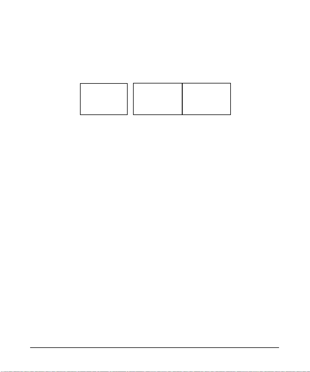
• This is the minimum legal X*screens file, the “Screen” keyword followed by
the screen device. Since no other information is given, the X Server will assume
default values for other options and settings.
Screen /dev/crt
Figure 2-1 Results of minimal legal X*screens file
X Server configuration
<
host
>:0.0
/dev/crt
• This is the minimum specification for a two-screen configuration. The
maximum number of screens supported on the X Server is four. Here, the
displays associated with /dev/crt0 and /dev/crt1 are referred to as
“<host>:0.0” and “<host>:0.1”, respectively.
Screen /dev/crt0
Screen /dev/crt1
Chapter 2 15
Page 18
configuring X Windows on HP-UX (HP Visualize graphics cards)
X Server configuration
Figure 2-2 Two physical displays, two separate screens
<
host
>:0.0
/dev/crt0
• This sample X*screens file could be used on a system using HP
VISUALIZE-FXE with a 17-inch monitor. In this example, the
GraphicsSharedMemorySize is decreased to 1 Mbyte in order to reduce the
swap space requirements of the system. Decreasing
GraphicsSharedMemorySize is appropriate when you do not intend to run any
3D graphics applications.
ServerOptions
GraphicsSharedMemorySize 0x100000
Screen /dev/crt
MonitorSize 17 inches
The display diagram would be the same as that of the “Results of Minimal
Legal X*screens File” configuration, above.
• This sample X*screens file could be used on a system with a HP
VISUALIZE-FX5 graphics device. The overlay visual is selected as the default.
There are 255 overlay colormap entries available on the HP VISUALIZE-FX5.
The 256th entry is hard-wired to transparent. Having less than 256 colormap
entries should not cause a problem for most applications, but for those
applications that require 256 colormap entries, the
CountTransparentInOverlayVisual screen option should be used as shown
below. Note that any attempts to modify the 256th entry will have no effect on
the colormap.
<
host
>:0.1
/dev/crt1
Screen /dev/crt
ScreenOptions
CountTransparentInOverlayVisual
The display diagram would be the same as that of the “Results of Minimal
Legal X*screens File” configuration, above.
• This sample X*screens file could be used on a system with a HP
VISUALIZE-FX10 graphics device. The default visual on the HP
VISUALIZE-FX10 is the opaque overlay visual. All 256 colormap entries are
opaque and allocable. If an application requires transparency in the default
visual, the “Transparent” keyword can be used to select the transparent overlay
visual as shown below.
Chapter 216
Page 19

configuring X Windows on HP-UX (HP Visualize graphics cards)
X Server configuration
Screen /dev/crt
DefaultVisual
Transparent
The display diagram would be the same as that of the “Results of Minimal
Legal X*screens File” configuration, above.
• This sample X*screens file could be used on a system with a HP
VISUALIZE-FXE graphics device. By default on the HP VISUALIZE-FXE,
the overlay visual does not have a transparent entry available to applications for
rendering transparency. If an application requires overlay transparency, an
optional X Server mode is available, but it is restrictive. In this optional mode,
only one hardware colormap is available in the overlays (instead of two) and
only one hardware colormap is available in the image planes (instead of two).
The optional X Server mode can be set via the EnableOverlayTransparency
screen option as shown below.
Screen /dev/crt
ScreenOptions
EnableOverlayTransparency
The display diagram would be the same as that of the “Results of Minimal
Legal X*screens File” configuration, above.
• These sample X*screens file entries could be used on a system with two
homogeneous graphics devices. Assuming the first device is associated with the
device file “/dev/crt0” and the second device is associated with the device
file “/dev/crt1”, both examples specify a horizontal Single Logical Screen
configuration.
SingleLogicalScreen 1 2
/dev/crt0 /dev/crt1
or
SingleLogicalScreen 1 2
/dev/crt0
/dev/crt1
Chapter 2 17
Page 20
configuring X Windows on HP-UX (HP Visualize graphics cards)
X Server configuration
Figure 2-3 Two physical displays, single logical screen (1x2)
<
host
>:0.0
/dev/crt0
• These sample X*screens entries could be used on a system with four
homogeneous graphics devices. Assuming the first device is
associated with the device file “/dev/crt0”, the second device is
associated with the device file “/dev/crt1”, etc. The following
examples specify valid Single Logical Screen configurations.
SingleLogicalScreen 1 4
/dev/crt0 /dev/crt1 /dev/crt2 /dev/crt3
Figure 2-4 Four physical displays, single logical screen (1x4)
<
host
/dev/crt0
/dev/crt1
/dev/crt1
>:0.0
/dev/crt2 /dev/crt3
SingleLogicalScreen 4 1
/dev/crt0
/dev/crt1
/dev/crt2
/dev/crt3
Chapter 218
Page 21
configuring X Windows on HP-UX (HP Visualize graphics cards)
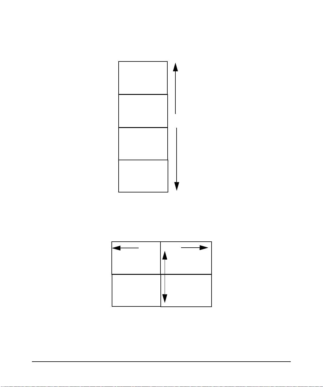
Figure 2-5 Four physical displays, single logical screen (4x1)
/dev/crt0
/dev/crt1
<
host
>:0.0
/dev/crt2
/dev/crt3
X Server configuration
SingleLogicalScreen 2 2
/dev/crt0 /dev/crt1
/dev/crt2 /dev/crt3
Figure 2-6 Four physical displays, single logical screen (2x2)
<
host
>:0.0
/dev/crt0
/dev/crt1
/dev/crt2 /dev/crt3
• It is possible to include a Screen Entry and an SLS Screen Entry in
the same X*screens File. This creates a situation where there are
two X Screens (e.g.< host>:0.0 and <host>:1.0), one of which happens
to be a Single Logical Screen. Below is an example of this:
Chapter 2 19
Page 22
configuring X Windows on HP-UX (HP Visualize graphics cards)
X Server configuration
Screen /dev/crt0
SingleLogicalScreen 1 2
/dev/crt1 /dev/crt2
Figure 2-7 Three physical displays, screen plus single logical screen(1x2)
<
host
>:0.0
/dev/crt0
/dev/crt1
<
host
>:0.0
/dev/crt2
miscellaneous topics
double buffer extensions
DBE is an extension to the X Server that provides a double-buffering
Application Programming Interface (API). For more information about
DBE and the API, consult the DBE man pages:
DBE
XdbeQueryExtension
XdbeGetVisualInfo
XdbeFreeVisualInfo
XdbeAllocateBackBufferName
XdbeDeallocateBackBufferName
XdbeSwapBuffers
XdbeBeginIdiom
XdbeEndIdiom
XdbeGetBackBufferAttributes
performing buffer swaps on vertical blank
For performance reasons , the default DBE beha vior is to not synchronize
buffer swaps with the monitor’s vertical retrace period. In some
instances, therefore, image tearing (seeing part of the old image and part
of the new image on the display at the same time) could be visible while
swapping large DBE windows. For those instances where tearing would
occur and is undesirable, an optional X Server mode is available to allow
for synchronization of buffer swaps with vertical retrace. To activate this
optional X Server mode, set the following screen option in the X*screens
File before the X Server is started:
SwapBuffersOnVBlank
Chapter 220
Page 23

configuring X Windows on HP-UX (HP Visualize graphics cards)
X Server configuration
determining swap performance
The DBE API does not allow users to determine if double-buffering in a
visual is through software or hardware. However, the API does provide a
way to determine relative swapping performance on a per-visual basis.
The XdbeScreenVisualInfo() function returns information about the
swapping performance levels for the double-buffering visuals on a
display. A visual with a higher performance level is likely to have better
double-buffer graphics performance than a visual with a lower
performance level. Nothing can be deduced from any of the following: the
magnitude of the difference of two performance levels, a performance
level in isolation, or comparing performance levels from different servers.
For more information, refer to the DBE man page on
XdbeScreenVisualInfo().
supported devices
The X Server supports DBE on the following devices:
• HP VISUALIZE-FX5 and FX10
• HP VISUALIZE-FXE
display power management signaling (DPMS)
Monitors constitute a large percentage of the power used by a
workstation even when not actively in use (i.e., during screen blanking).
In order to reduce the power consumption, the Video Electronic
Standards Association (VESA) has defined a Display Power Management
Signaling (DPMS) standard which can be used to greatly reduce the
amount of power being used by a monitor during screen blanking.
The X Server features the ability to make use of DPMS on the following
graphics devices:
• HP VISUALIZE-FX5 and FX10
• HP VISUALIZE-FXE
Chapter 2 21
Page 24
configuring X Windows on HP-UX (HP Visualize graphics cards)
X Server configuration
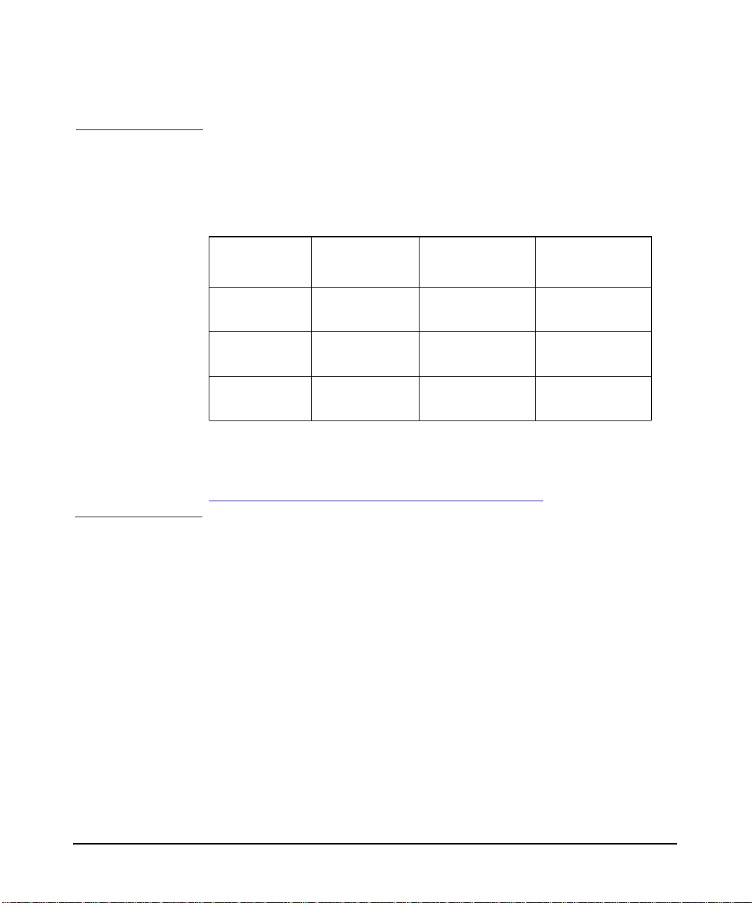
The following table is a description of the states that are defined by
VESA. The Power Savings column indicates (roughly) the level of power
savings achieved in the given state. The Recovery Time is the amount of
time that the screen takes to return to a usable state when the screen
saver is turned off (by pressing a key or the moving the mouse).
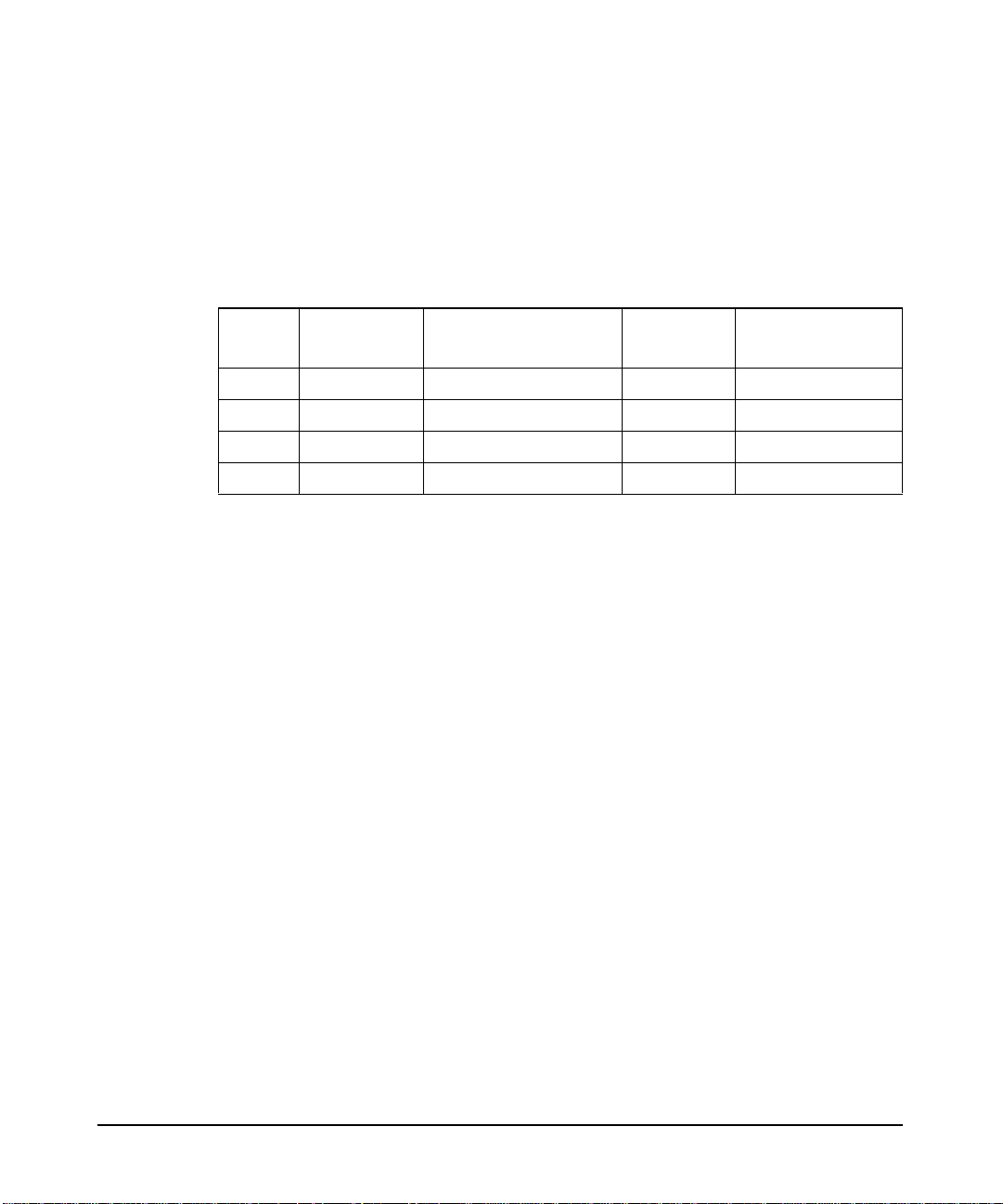
Table 2-1 Power saving states defined by VESA
Level State
0 Screen Saver Not Applicable None Very Short (<1sec.)
1 Stand-by Optional Minimal Short
2 Suspend Mandatory Substantial Longer
3 Off Mandatory Maximum System Dependent
DPMS Compliance
Requirements
Power
Savings
Recovery Time
The actual amount of power saved and the recovery time for each of the
states is monitor-dependent and may vary widely. The customer can
compensate for this by choosing an appropriate level for the monitor that
is currently in use.
By default, the DPMS level used is the Screen Saver (i.e. no power
savings). If you wish to use power saving during screen blanking, set the
following X*screens file entry before starting the server:
MinimumMonitorPowerSaveLevel <level>
where level is replaced with the single digit 0, 1, 2, or 3 as specified in the
Level column in the above table.
shared memory extension (MIT_SHM)
The MIT shared memory extension provides both shared-memory
XImages and shared-memory pixmaps based on the SYSV shared
memory primitives.
Shared memory XImages are essentially a version of the XImage
interface where the actual image data is stored in a shared memory
segment, and thus need not be moved through the Xlib interprocess
communication channel. For large images, use of this facility can result
in increased performance.
Shared memory pixmaps are a similar concept implemented for the
pixmap interface. Shared memory pixmaps are two-dimensional arrays
of pixels in a format specified by the X Server, where the pixmap data is
Chapter 222
Page 25

configuring X Windows on HP-UX (HP Visualize graphics cards)
X Server configuration
stored in the shared memory segment. In all other respects, shared
memory pixmaps behave the same as ordinary pixmaps and can be
modified by the usual Xlib routines. In addition, it is possible to change
the contents of these pixmaps directly without the use of Xlib routines
merely by modifying the pixmap data.
supported devices
The X Server supports the MIT shared memory extension on the
following devices:
• HP VISUALIZE-FX5 and FX10
• HP VISUALIZE-FXE
supported X configurations
multi-display support
The following definitions are included to reduce confusion between the
terms “multi-display,” “multi-screen,” and “single logical screen.”
Multi-Display
A configuration with multiple graphics devices used concurrently. Any
multi-screen or single logical screen configuration is referred to as a
multi-display configuration.
Chapter 2 23
Page 26
configuring X Windows on HP-UX (HP Visualize graphics cards)
X Server configuration
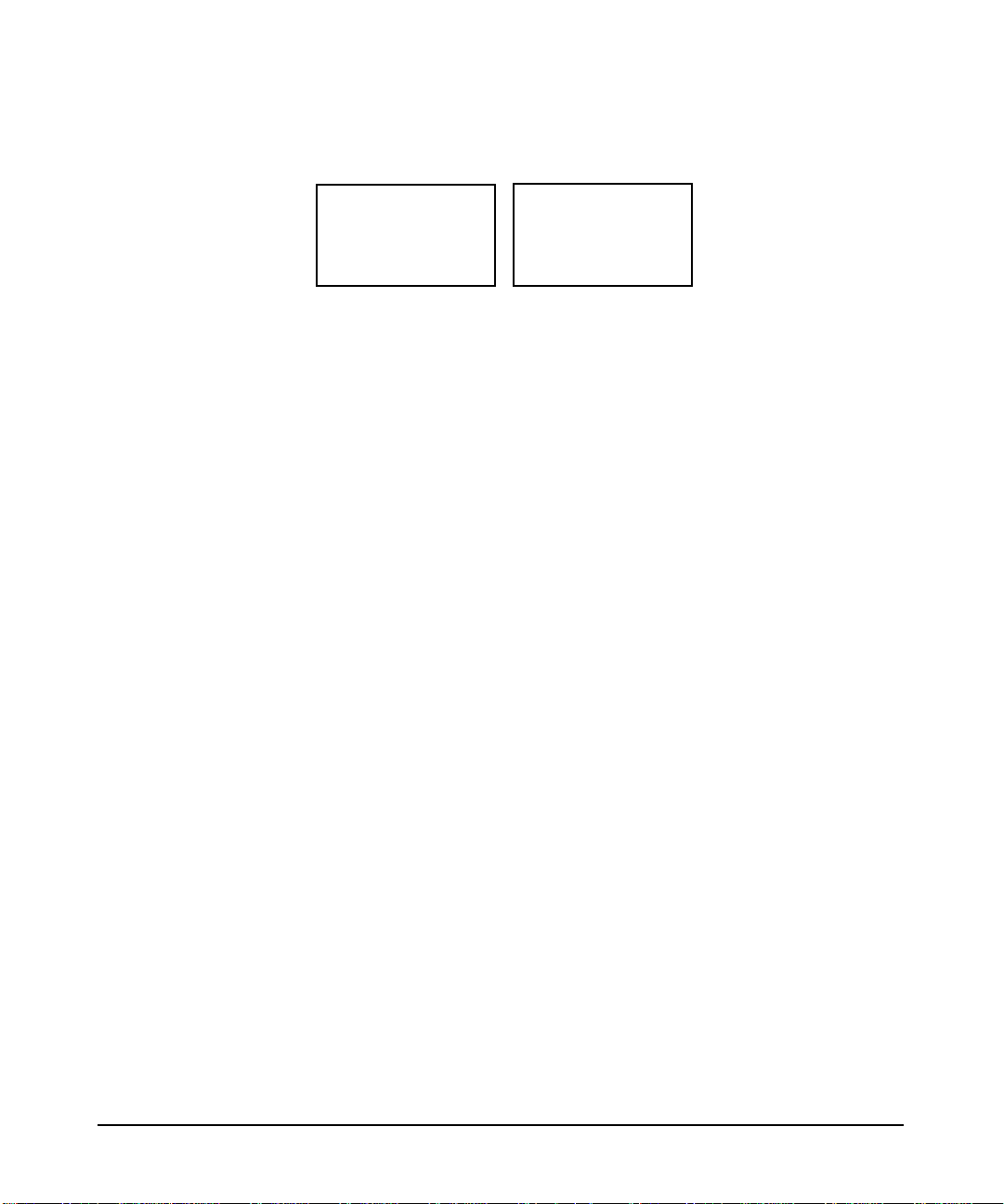
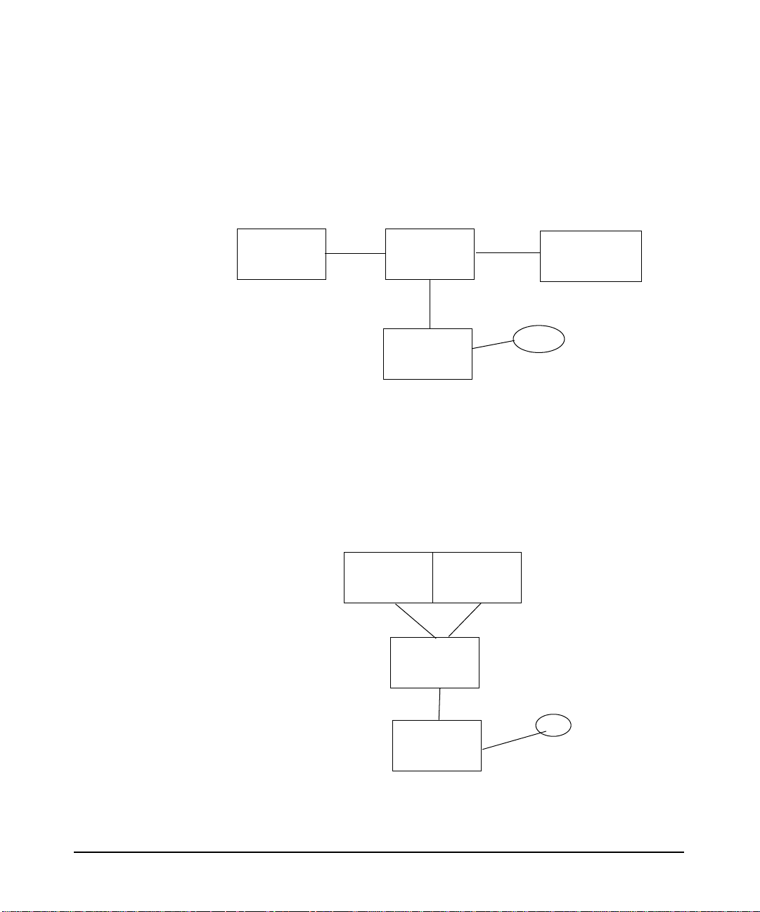
Multi-Screen
A configuration in which a single X Server with a mouse and keyboard
drives multiple graphics devices (where each display is a different X
Screen) concurrently while only allowing the cursor, not windows, to be
moved between displays.
Device #1
host:0.0
(1280x1024)
SPU
Keyboard
Device #2
host:0.1
(1280x1024)
Mouse
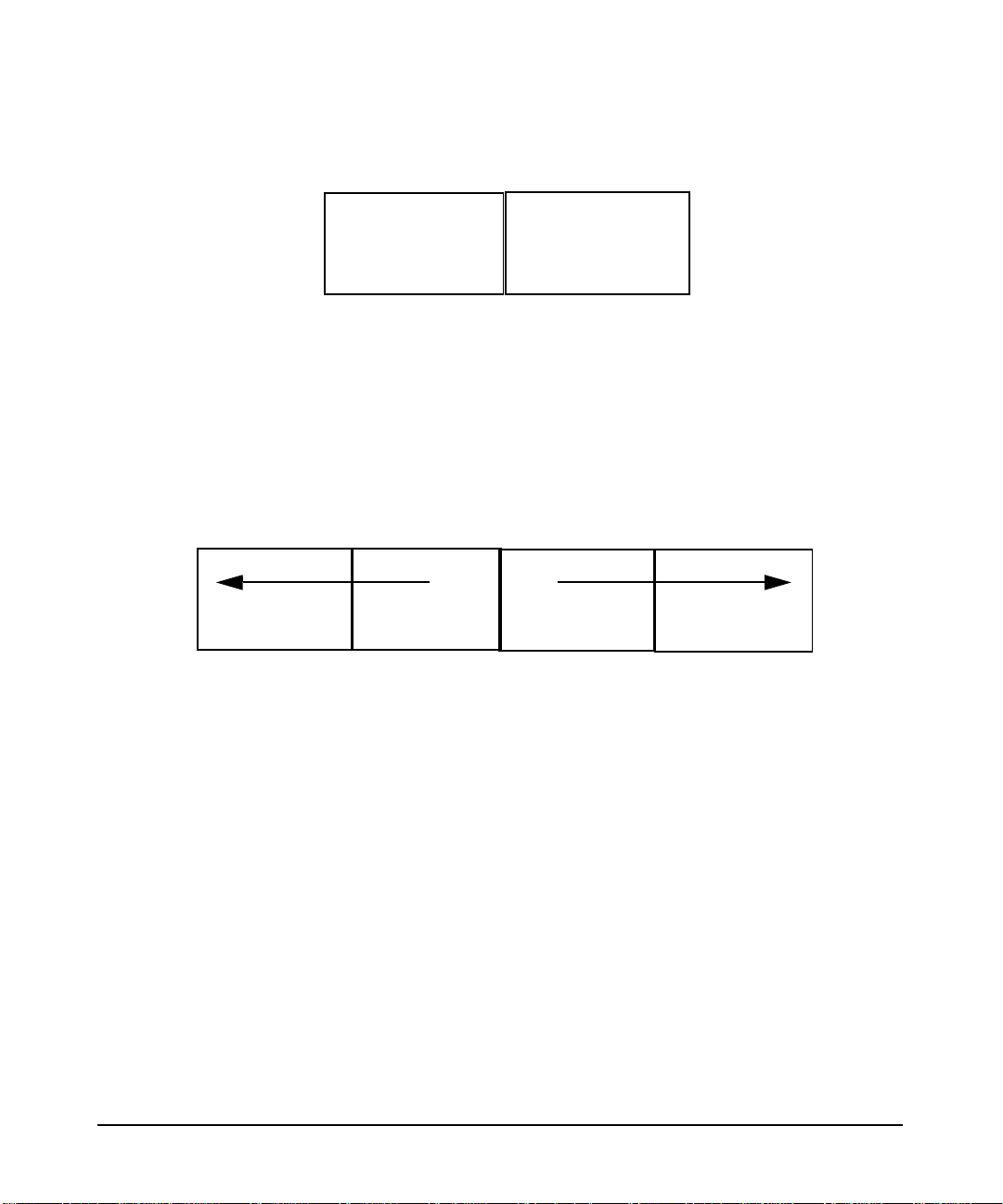
Single logical screen
A configuration in which a single X Server with a single mouse and
keyboard drives multiple homogeneous graphics devices concurrently
while allowing the displays to emulate a large single screen. This differs
from a multi-screen environment by allowing windows to be moved and
displayed across displays. See the section in this document on Single
Logical Screen.
host:0.0
(2560x1024)
Device #1
Device #2
SPU
Keyboard
Mouse
Note that different monitor resolutions are not supported with the
multi-display configurations unless stated otherwise in the table below.
Chapter 224
Page 27

configuring X Windows on HP-UX (HP Visualize graphics cards)
X Server configuration
multi-screen support
The list of supported multi-display configurations is rather large, and it
changes whenever a new graphics device is introduced. Thus, if you are
considering a Single Logical Screen or any other multi-display
configuration, we recommend consulting your HP Sales Representative
and inquiring whether the configuration you have in mind is indeed
supported.
There are general guidelines, however. For example:
• Multi-display configurations may be limited by available power.
Depending on the capacity of your computer’s power supply, and the
power demands of the combination of graphics cards you are
considering, there may or may not be enough power to operate them
all.
• Single Logical Screen configurations must use identical graphics
devices (see the next section).
single logical screen (SLS)
SLS is a mechanism for treating homogeneous multi-display
configurations as a single “logical” screen. This allows the
moving/spanning of windows across multiple physical monitors. The
word “homogeneous” is included because SLS only works if the graphics
devices included in the SLS Configuration are of the same type.
SLS is enabled by using SAM (the System Administration Manager tool,
/usr/sbin/sam). To enable an SLS configuration, start SAM, and
follow the instructions below:
1. Double-click on the “X Server Configuration” button. A window
entitled “Graphics” appears, containing an icon for every graphics device
on your system.
2. Select the devices you want to combine into an SLS (click the mouse on
the first device, and [Ctrl]-click on the others). At this point, all the
devices you want to combine into an SLS configuration should be
highlighted.
3.From the “Actions” menu, choose the menu item “Modify Multi-Screen
Layout”. A dialog box appears, allowing you to specify exactly how you
want your SLS configuration to be.
Chapter 2 25
Page 28

configuring X Windows on HP-UX (HP Visualize graphics cards)
X Server configuration
Note that if your machine has only one graphics device, the “Modify
Multi-Screen Layout” menu option does not even appear, since multiple
devices cannot occur in a single-device context.
Note also that DHA (Direct Hardware Access) is supported in a window
that spans multiple screens.
“Spanning,” in this context, includes a window that is two or more
screens in size, as well as a window that is partially on one screen and
partially on another (even though it would fit on a single screen if it were
moved).
SLS can also be enabled via the /etc/X11/X*screens file via the syntax:
SingleLogicalScreen n m
/dev/crt0 ... /dev/crtk
where:
n = the number of “rows” in the physical configuration,
m = the number of “columns” in the physical configuration,
and the product of n x m is less than or equal to four.
For example, to create a logical screen that is one monitor tall by two
monitors wide, the following syntax would be used:
SingleLogicalScreen 1 2
/dev/crt0 /dev/crt1
Whereas for a logical screen that is two monitors tall by one monitor
wide, the syntax is:
SingleLogicalScreen 2 1
/dev/crt0 /dev/crt1
3D acceleration and single logical screen
Currently, SLS does not take advantage of 3D acceleration (e.g. Visualize
FX5). 3D applications (from any supported HP 3D API) will continue to
run with SLS; However, 3D performance with SLS will be much slower
than it is without SLS.
hp CDE and single logical screen
Please note that HP CDE has not been modified to take advantage of the
Single Logical Screen capability. When presenting information on your
display, HP CDE may split a window across physical screens. Examples
include:
Chapter 226
Page 29

configuring X Windows on HP-UX (HP Visualize graphics cards)
X Server configuration
• The login screen.
• The Front Panel.
• Window move and resize boxes.
• The screen lock dialog.
This behavior is the result of HP CDE’s naive assumption that it is
running against one large screen; it centers these windows accordingly.
If you are using the default HP CDE key bindings, you can easily
reposition the Front Panel so that it is completely contained within one
physical screen:
1. With the input focus on the Front Panel, press
Alt and Space.
2. With the Front Panel menu posted and the “Move” menu item
selected, press
Enter (on older keyboards ,Return) to start the move.
3. Use the mouse or the arrow keys to reposition the Front Panel to the
desired location.
4. Press
Esc
Enter (or Return) to complete the move. You may instead press
to cancel the move.
Afterwards, this setting will be remembered and restored at your next
login. If you have previously set a Home session, you will need to re-set
the Home session in the Style Manager to register the new Front Panel
position.
Note that there is no mechanism in HP CDE for repositioning the login
screen, window move/resize boxes, or the screen lock dialog.
Chapter 2 27
Page 30

configuring X Windows on HP-UX (HP Visualize graphics cards)
hp Visualize- FXE, FX5 and FX10 device-dependent information
hp Visualize- FXE, FX5 and FX10
device-dependent information
This section includes information on the HP VISUALIZE-FXE/5/10
graphics devices.
The HP VISUALIZE-FXE/5/10 has 8 overlay planes, 48 image planes a
24-bit z buffer and 4 hardware colormaps.
HP VISUALIZE-FXE/5/10 graphics devices contain 2D hardware
acceleration similar to that in other HP VISUALIZE devices, as well as
3D acceleration for lighting, shading and texture mapping.
supported visuals
HP VISUALIZE-FXE/5/10 graphics devices support all of the following
visuals:
• Class PseudoColor Depth 8 Layer Image
• Class PseudoColor Depth 8 Layer Overlay
• Class PseudoColor Depth8 Layer Overlay Transparent
• Class DirectColor Depth 24 Layer Image
• Class TrueColor Depth 24 Layer Image
The following visuals are enabled by default on the HP
VISUALIZE-FXE/5/10:
• Class PseudoColor Depth 8 Layer Image
supports DBE hardware double-buffering
• Class PseudoColor Depth 8 Layer Overlay
supports DBE software double-buffering
• Class PseudoColor Depth 8 Layer Overlay Transparent
supports DBE software double-buffering
• Class DirectColor Depth 24 Layer Image
does not support DBE hardware or software double-buffering
• Class TrueColor Depth 24 Layer Image
does not support DBE hardware or software double-buffering
NOTE When running xdpyinfo or calling the XGetVisualInfo() Xlib
function, some extra duplicate visuals may appear in the visual list.
These extra visuals are created on behalf of the OpenGL extension to
Chapter 228
Page 31

configuring X Windows on HP-UX (HP Visualize graphics cards)
hp Visualize- FXE, FX5 and FX10 device-dependent information
X (GLX). If necessary, the extra visuals can be disabled using the
DisableGLxVisuals screen option. See the “Disabling the GLX
Visuals” section for more information.
supported screen options
The following screen options are supported:
• CountTransparentInOverlayVisual
• ImageTextViaBitMap
• EnableIncludeInferiorsFix
• DisableGlxVisuals
hp VISUALIZE-FXE/5/10 configuration hints
overlay visuals and overlay transparency
HP VISUALIZE-FXE/5/10 devices have two visuals in the overlay
planes, both depth-8 PseudoColor. The first (default) overlay visual has
256 entries per colormap and no transparency. The second overlay visual
has 255 entries per colormap and supports transparency.
To allow applications to determine which visuals are in the overlay
planes, both overlay visuals are listed in the
SERVER_OVERLAY_VISUALS property attached to the root window.
The default overlay visual has a transparent type of “0” (None), while the
transparent overlay visual has a transparent type of “1”
(TransparentPixel).
If you need an overlay colormap that supports transparency, create the
colormap using the visual that has transparency in its
SERVER_OVERLAY_VISUALS property.
disabling the GLX visuals
The HP VISUALIZE-FXE/5/10 products support the OpenGL extension
to X (GLX). If HP OpenGL is installed on an HP VISUALIZE-FXE/5/10
system, then the GLX extension offers new entry points for obtaining
more information about X visuals. As part of offering extended visual
information, some extra X visuals appear in the X visual list. The extra
Chapter 2 29
Page 32

configuring X Windows on HP-UX (HP Visualize graphics cards)
hp Visualize- FXE, FX5 and FX10 device-dependent information
visuals are simply duplicates of visuals that would normally appear in
the X visual list. In case that the extra visuals cause problems with
applications, a screen option can be used to disable them.
To disable the GLX visuals, add the DisableGlxVisualsScreen Option to
the X*screens file.For example:
Screen /dev/crt/
ScreenOption
DisableGlxVisuals
hp VISUALIZE-FXE/5/10 colormaps
HP VISUALIZE-FXE/5/10 devices have a total of 4 hardware colormaps .
2 of the colormaps are dedicated to the overlay planes. The remaining 2
colormaps are dedicated to the image planes.
Of the two overlay colormaps, one is permanently reserved for the
default colormap. The other overlay colormap is available to applications .
changing the monitor type
A configuration tool is available to change the monitor type on HP
VISUALIZE-FXE/5/10 devices. This tool permits users to change the
monitor’s refresh rate, frame buffer resolution, and frame buffer memory
configuration (e.g., Stereo, Double Buffer), when the device supports
multiple options. To change the monitor type, the setmon command can
be executed directly or done through the SAM system administration
tool.
The setmon executable is located at /opt/graphics/common/bin/setmon.
Under SAM this component is located under the top-level “Display”
folder, next to the “X Server Configuration” icon.
NOTE Changing the monitor type while the X Server is running will necessitate
killing and restarting the X Server.
Chapter 230
Page 33

3 configuring X Windows on HP-UX
(other graphics cards)
This chapter documents information specific to the HP Xf86 X Server.
The Xf86 X Server is based on the XFree86 version 4.2.0 X Server. This
Chapter 3 31
Page 34

configuring X Windows on HP-UX (other graphics cards)
section describes features unique to HP's implementation of the X
Server, provides information on how to configure the X Server and
includes a list of supported X configurations. For each supported
graphics device, device-dependent configuration information is provided.
NOTE This chapter deals with configuration requirements for graphics cards
OTHER THAN HP Visualize cards (fxe, fx5, fx10, etc.). For configuration
information for all HP Visualize cards, refer to Chapter 2 in this
document.
Chapter 332
Page 35

configuring X Windows on HP-UX (other graphics cards)
using SAM to configure X Windows
using SAM to configure X Windows
Configuration of the X Server is supported through SAM via an icon
titled “X Server Configuration.” This icon resides either at SAM’s
top-level or under the top-level “Display” icon.
The SAM graphical user interface for X Server configuration is provided
to simplify complexity and facilitate ease of use in modifying or creating
the X Server configuration file, XF86Config. The Xf86 server uses the
XF86Config file for its configurations. While it is still possible to modify
this file manually (see below), using the SAM interface can greatly
simplify the process.
The SAM component has the following actions:
• Configure Print Server...
• Configure How X Starts...
• Modify Multi-Screen Layout...
• Single Logical Screen (SLS) ->
--------------------------------------------------
• Describe Screen...
• Identify Screen
• Modify Default Visual...
• Modify Screen Options...
• Modify Server Options...
• Add Screen to Configuration
• Remove Screen from Configuration
The first group of Actions menus can be thought of as global actions.
They will typically be active regardless of what has been selected. If any
of these menu items are not visible it is because they are not supported
under the current configuration.
The Configure Print Server item allows you to manage print servers.
From this menu item you can create, stop or remove print servers.
On systems that contain a mix of HP Visualize and other HP graphics
cards, the Configure How X Starts item allows you to choose on which
graphics devices the X Server should start. From this action, you can
assign which of your configuration files to use as a display connection the X* screens file for HP graphics cards or the XF86Config file with
Chapter 3 33
Page 36

configuring X Windows on HP-UX (other graphics cards)
using SAM to configure X Windows
other graphics cards. Running independent X Servers on an HP
Visualize graphics device and any other device simultaneously is not
supported.
SLS is a mechanism for treating homogeneous multi-display
configurations as a single logical screen. This allows the
moving/spanning of windows across multiple physical monitors. The
word homogeneous is included because SLS only works if the graphics
devices included in the SLS Configuration are of the same type.
To enable an SLS configuration, start SAM, select the "Display" icon, and
follow the instructions below:
1. Double-click on the "X Server Configuration" button. A window
entitled "X Server Configuration" appears, containing an icon for every
graphics device on your system.
2. Select the devices you want to combine into an SLS configuration. To
select the devices, click the mouse on the first device, and
the others. At this point, all the devices you want to combine into an SLS
configuration should be highlighted.
3. From the "Actions" menu, choose the it "Single Logical Screen (SLS)"
-> "Create SLS..."
[Ctrl]-click on
4. In the "Create SLS" screen, select the desired layout (horizontal or
vertical) and screen mapping, and click "OK".
5. The "X Server Configuration" window should now show a single icon
denoting an SLS confguration.
6. Select "File -> Exit". This will save the new SLS configuration and
give you the option to restart the Xserver. The Xserver will need to be
restarted for the new SLS configuration settings to take effect.
Specific Xf86 server options can be set with the Modify Server Options
menu item. See the item for information on specific options.
The second group of “ Actions” menus can be thought of as screen actions .
They will be activated depending on which screens have been chosen.
The windows that result from choosing on of these actions differ
depending upon whether the selected screen is an HP Visualize graphics
card or other HP graphics cards.
The Describe Screen and Identify Screen menu selections provide
information about the device. Identify Screen flashes the monitor that
is connected to the graphics device.
Chapter 334
Page 37

configuring X Windows on HP-UX (other graphics cards)
using SAM to configure X Windows
The Modify Default Visual menu item lets you set the default visuals,
depth and resolution on a graphics device. It lets you identify which of
these should be the default settings.
The Modify Screens Options item contains options that are specific to
each graphics device. This list might be different for cards depending on
the capabilities of each card.
Grayed out screen icons represent screens that have not been configured
for use by the X Server. You can select these grayed out icons and choose
the Add Screen to Configuration menu item to add screens to the
configuration file. HP Visualize graphics devices are added to the
X*screens file and other HP graphics devices are added to the
XF86Config file.
More information on configuration of the X Server and each of the above
actions can be obtained from SAMs on-line Help.
using setmon to configure the monitor
setmon is a configuration tool used to change the monitor settings for a
monitor attached to a graphics device. This tool permits you to change
the monitor's refresh rate, frame buffer resolution, and frame buffer
memory configuration (e.g., Stereo, Double Buffer), when the device
supports multiple options. To change the monitor type, the setmon
command can be executed directly or done through SAM.
The setmon executable is located at
/opt/graphics/common/bin/setmon. Under SAM this component is
located under the top-level “Display” folder, next to the “X Server
Configuration” icon.
NOTE Changing the monitor type while the X Server is running will necessitate
killing and restarting the X Server. In order to change the monitor
settings, the X Server needs to be running on the device specified. For
these graphics cards, it may not be possible to test some of the monitor
settings before making the change permanent.
Chapter 3 35
Page 38

configuring X Windows on HP-UX (other graphics cards)
the XF86Config file
the XF86Config file
The XF86Config file is located in /etc/X11/XF86Config. It can be
generated automatically or modified using SAM. A working
configuration file is also delivered on the system. You must be root to
create or edit this file. The XF86Config man page provides additional
information regarding the configuration file. It is necessary to re-start
the X Server for changes made to the XF86Config file to take effect.
the XF86Config file format
Most of the content in this section has been copied from the
XF86Config(5) man page listed on “The XFree86 Project, Inc.” web site
(http://www.xfree86.org). The man pages are available from
http://www.xfree86.org/4.2.0
Config file keywords are case-insensitive, and underscore “_” characters
are ignored. Most strings (including Option names) are also
case-insensitive, and insensitive to white space and underscore “_”
characters.
Each config file entry usually takes up a single line in the file. They
consist of a keyword, which is possibly followed by one or more
arguments, with the number and types of the arguments depending on
the keyword. The argument types are:
• Integer - an integer number in decimal, hex or octal
• Real - a floating point number
• String - a string enclosed in double quote marks (“)
NOTE Hex integer values must be prefixed with “0x”, and octal values with “0”.
A special keyword called Option may be used to provide free-form data
to various components of the server. The Option keyword takes either
one or two string arguments. The first is the option name, and the
optional second argument is the option value. Some commonly used
option value types include:
• Integer - an integer number in decimal, hex or octal
• Real - a floating point number
Chapter 336
Page 39

configuring X Windows on HP-UX (other graphics cards)
the XF86Config file
• String - a sequence of characters
• Boolean - a boolean value (see below)
• Frequency - a frequency value (see below)
NOTE All Option values, not just strings, must be enclosed in quotes.
Boolean options may optionally have a value specified. When no value is
specified, the option's value is TRUE. The following boolean option
values are recognized as TRUE:
1, on, true, yes
and the following boolean option values are recognized as FALSE:
0, off, false, no
If an option name is prefixed with “No”, then the option value is negated.
Frequency option values consist of a real number that is optionally
followed by one of the following frequency units:
Hz, k, kHz, M, MHz
When the unit name is omitted, the correct units will be determined from
the value and the expectations of the appropriate range of the value. It is
recommended that the units always be specified when using frequency
option values to avoid any errors in determining the value.
“ServerLayout” section
The ServerLayout section is used to identify which Screen sections are
to be used in a multi-headed configuration, the relative layout of those
screens, and which InputDevice sections are to be used. Each
ServerLayout section has an Identifier, a list of Screen section
identifiers, and a list of InputDevice section identifiers. Options may
also be included in the ServerLayout section. A ServerLayout section
may be made active by referencing (via its Identifier) on the command
line that starts X. In the absence of this, the first one found in the file
will be chosen by default, as there may be multiple ServerLayout
sections in the config file. The format of the ServerLayout section is as
follows:
Chapter 3 37
Page 40

configuring X Windows on HP-UX (other graphics cards)
the XF86Config file
Section ìServerLayoutî
Identifier ìServerLayoutNameî
Screen [ScreenNumber] ìScreenIDî [Position] [Xcoor] [Ycoor]
. . .
InputDevice ìInputDeviceIDî ìInputDeviceOptionî
. . .
[Option Ö]
. . .
EndSection
Keywords, options and values enclosed in [ ] are optional.
A number specifying the preferred screen number for that screen may
optionally follow each Screen. When no screen number is specified, it is
numbered according to the order in which it is listed. Next comes the
ScreenID, a required field that must be enclosed in double quotes. The
ScreenID must match an Identifier in a Screen section. The
remaining information on the line is optional. Next comes the physical
position of the screen, either in absolute terms or relative to another
screen (or screens). Finally the XY coordinates of the screen may be
specified.
The position keywords are:
Absolute
RightOf
LeftOf
Above
Below
Relative
The preferred method of specifying the layout is to explicitly specify the
screen's location in absolute terms or relative to another screen.
The examples are based on the examples listed in the DESIGN document
from XFree86.
In the absolute case, the upper left corner's coordinates are given after
the Absolute keyword. If the coordinates are omitted, a value of (0,0) is
assumed. An example of absolute positioning follows:
Chapter 338
Page 41

configuring X Windows on HP-UX (other graphics cards)
the XF86Config file
Section ìServerLayoutî
Identifier ìMainLayoutî
Screen 0 ìScreen 1" Absolute
Screen 1 ìScreen 2" Absolute 1024 0
Screen ìScreen 3" Absolute 2048 0
. . .
EndSection
When the Relative keyword is used, the coordinates of the new screen's
origin relative to reference screen follow the reference screen name. The
following example shows how to use some of the relative positioning
options:
Section ìServerLayoutî
Identifier ìMain Layoutî
Screen 0 ìScreen 1"
Screen 1 ìScreen 2ì RightOf ìScreen 1"
Screen ìScreen 3" Relative ìScreen 1" 2048 0
. . .
EndSection
Each InputDevice is followed by an InputDeviceID, a required field
that must be enclosed in double quotes. The InputDeviceID must match
an Identifier in an InputDevice section. Last, an option may be
provided. The option can also be specified in the InputDevice section.
Typical options specified here are: CorePointer, CoreKeyboard, and
SendCoreEvents. The option must be enclosed in double quotes. See
the InputDevice section for more information regarding the options.
Normally, at least two InputDevices are present: a keyboard and a
mouse.
Options that apply to the X Server may also be specified in this section.
The following table lists all options that may be set in the
ServerLayout section.
Chapter 3 39
Page 42

configuring X Windows on HP-UX (other graphics cards)
the XF86Config file
Table 3-1
Option Value Default Description
DontZap Boolean Off This disallows the use of the
DontZoom Boolean Off This disallows the use of the
Ctrl+Shift+Break sequence. That
sequence is normally used to
terminate the X Server. When this
option is enabled, that key sequence
has no special meaning and is passed
to clients. Source: XF86Config man
page.
Ctrl+Alt+Keypad-Plus and
Ctrl+Alt+Keypad-Minus sequences.
These sequences allow you to switch
between video modes. When this
option is enabled, those key sequences
have no special meaning and are
passed to clients. Source: XF86Config
man page.
AllowMouseOpenFail Boolean false This allows the server to start up even
if the mouse device can't be
opened/initialized.Source: XF86Config
man page.
Pixmap Bpp 32 This sets the pixmap format to use for
depth 24. Allowed values for bpp are
24 and 32. Default: 32 unless driver
constraints don't allow this (which is
rare). Note: some clients don't behave
well when this value is set to 24.
Source: XF86Config man page.
Verbose Integer -1 See the section on “Features: Logging
and Verbosity” for more details
regarding these options.
NoLogging NA NA See the section on “Features: Logging
and Verbosity” for more details
regarding these options.
LogVerbose Integer -1 See the section on “Features: Logging
and Verbosity” for more details
regarding these options.
Chapter 340
Page 43

Table 3-1 (Continued)
CursorScaleFactor Integer 1 See the section in “Features: ” for more
MaxCursorSize Integer 64 See the section in “Features: Cursor
AcelerateIndirectRendering Boolean True This option is used to specify whether
“Files” section
The Files section is used to specify paths to where fonts and modules are
located and the location of the rgb database and the user specified logfile.
The Files section format is:
ìFilesî Section
Endsection
configuring X Windows on HP-UX (other graphics cards)
the XF86Config file
details regarding these options.
Scaling” for more details regarding
these options.
or not OpenGL is to do software
rendering. A value of False forces
software rendering. The default is for
OpenGL to use accelerated rendering.
[FontPath ìPathNameî]
.
.
[ModulePath ìPathNameî]
.
.
[RgbPath ìPathNameî]
[LogPath ìPathNameî]
Multiple Font Paths and Module Paths may be specified in two ways,
either by multiple lines or by using a “,” delimiter between paths on the
same line.
Font Path elements may be either absolute directory paths, or a font
server identifier. Font server identifiers have the form:
<trans>/<hostname>:<port-number>
Chapter 3 41
Page 44

configuring X Windows on HP-UX (other graphics cards)
the XF86Config file
where <trans> is the transport type to use to connect to the font server
(e.g., Unix for UNIX-domain sockets or tcp for a TCP/IP connection),
<hostname> is the hostname of the machine running the font server, and
<port-number> is the port number that the font server is listening on
(usually 7000). The default Font Path is:
tcp:/7000,
/usr/lib/X11/fonts/hp_roman8/75dpi/,
/usr/lib/X11/fonts/iso_8859.1/100dpi/,
/usr/lib/X11/fonts/iso_8859.1/75dpi/,
/usr/lib/X11/fonts/hp_kana8/,
/usr/lib/X11/fonts/hp_japanese/100dpi/,
/usr/lib/X11/fonts/hp_japanese/75dpi/,
/usr/lib/X11/fonts/hp_korean/75dpi/,
/usr/lib/X11/fonts/hp_chinese_s/75dpi/,
/usr/lib/X11/fonts/hp_chinese_t/75dpi/,
/usr/lib/X11/fonts/iso_8859.2/75dpi/,
/usr/lib/X11/fonts/iso_8859.5/75dpi/,
/usr/lib/X11/fonts/iso_8859.6/75dpi/,
/usr/lib/X11/fonts/iso_8859.7/75dpi/
/usr/lib/X11/fonts/iso_8859.8/75dpi/,
/usr/lib/X11/fonts/iso_8859.9/75dpi/,
/usr/lib/X11/fonts/misc/
Xf86 uses ModulePaths as locations to look for loadable modules. The
default ModulePath is:
/usr/lib/X11/Xserver/modules/xf86/,
/opt/graphics/common/lib/
RgbPath can be used to specify the RGB database path. Normally it is
never changed. If it is not specified the built-in path /etc/X11/rgb is
used.
In addition, the LogPath can be specified, if server logging information
is to be sent somewhere other than the default log file. The default logfile
is located at /var/X11/Xserver/logs/Xf86.n.log, where n is the
display number.
All names must be enclosed within double quotes. There may be only one
Files section in the config file. This section does not recognize Option as
a keyword.
Chapter 342
Page 45

configuring X Windows on HP-UX (other graphics cards)
the XF86Config file
“Module” section
The Module section is used to specify which X Server modules should be
loaded. The types of modules normally loaded in this section are X Server
extension modules, and font rasterizer modules. Most other module types
are loaded automatically when they are needed via other mechanisms.
There may only be one Module section in the config file. The format of
the Module section is as follows:
Section ìModuleî
Load ìModuleNameî
. . .
[SubSection ìModuleNameî
Option . . .
. . .
EndSubSection]
. . .
EndSection
.
Load instructs the server to load the module called ModuleName. The
module name given should be the module's extension name, not the
module file name. The extension name is case-sensitive, and does not
include the “lib” prefix, or the “.1” suffix.
Example: the Double Buffered Extension (DBE) can be loaded with the
following entry:
Load ìdbeî
SubSection also instructs the server to load the module called
ModuleName. The module name given should be the module's
extension name, not the module file name. The extension name is
case-sensitive, and does not include the “lib” prefix, or the “.1” suffix. The
difference is that the listed Options are passed to the module when it is
loaded.
Modules are searched for in each directory specified in the ModulePath
search path (or the default ModulePath if one is not specified in the
Files section) and in the drivers, input, extensions, fonts, and HP-UX
subdirectories of each directory in the ModulePath.
Chapter 3 43
Page 46

configuring X Windows on HP-UX (other graphics cards)
the XF86Config file
“InputDevice” section
An InputDevice section is considered active if there is a reference to it
in the active ServerLayout section. There may be multiple
InputDevice sections. There will normally be at least two: one for the
core (primary) keyboard, and one for the core pointer. InputDevice
sections have the following format:
Section ìInputDeviceî
Identifier ìInputDeviceIDî
Driver ìDriverNameî
[Option Ö]
. . .
EndSection
The Identifier entry specifies the unique name for this input device and
must match an InputDeviceID in the active ServerLayout section in
order to be active.
The Driver entry specifies the name of the driver to use for this input
device.
InputDevice sections recognize some driver-independent Options,
which are described here. See the individual input driver manual pages
for a description of the device-specific options that can be entered here.
Table 3-2
Option Value Description
CorePointer NA When this is set, the input device is
installed as the core (primary) pointer
device. There must be no more than one
core pointer. If this option is not set here, or
in the ServerLayout section, or from the
-pointer command line option, then the first
input device that is capable of being used as
a core pointer will be selected as the core
pointer. Source: XF86Config man page.
Chapter 344
Page 47

configuring X Windows on HP-UX (other graphics cards)
the XF86Config file
Table 3-2 (Cont inued)
CoreKeyboard NA When this is set, the input device is to be
installed as the core (primary) keyboard
device. There must be no more than one
core keyboard. If this option is not set here,
or in the ServerLayout section, then the
first input device that is capable of being
used as a core keyboard will be selected as
the core keyboard. Source: XF86Config man
page.
AlwaysCore
SendCoreEvents
HistorySize number Sets the motion history size. Default: 0.
boolean Both of these options are equivalent, and
when enabled cause the input device to
always report core events. This can be used,
for example, to allow additional pointer
devices to generate core pointer events
(such as moving the cursor, etc). Source:
XF86Config man page.
Source: XF86Config man page.
The following two examples show an InputDevice section for a
keyboard and mouse:
Section ìInputDeviceî
Identifier ìKeyboard0î
Driver ìkeyboardî
EndSection
Section ìInputDeviceî
Identifier ìMouse0î
Driver ìmouseî
Option ìProtocolî ìPS/2î
EndSection
“Screen” section
The configuration file may have multiple Screen sections. There must
be at least one, for the “screen” being used. A “screen” binds a graphics
device (Device section) and a monitor (Monitor section) together. A
Screen section is considered “active” if it is referenced by an active
Chapter 3 45
Page 48

configuring X Windows on HP-UX (other graphics cards)
the XF86Config file
ServerLayout section. If neither of these is present, the first Screen
section found in the configuration file is considered the active one.
Screen sections have the following format:
Section ìScreenî
Identifier ìScreenIDî
Device ìDeviceIDî
Monitor ìMonitorIDî
DefaultDepth <Depth>
Option ...
.
.
SubSection ìDisplayî
.
.
EndSubSection
.
EndSection
The Identifier entry specifies the unique name for this screen. The
Identifier generally must match a ScreenID listed in the active
ServerLayout section. The Screen section provides information
specific to the whole screen, including screen-specific Options. In
multi-screen configurations, there will be multiple active Screen
sections, one for each head.
The Device keyword specifies which Device section to be used for this
screen. This is what binds a specific graphics card to a screen. The
DeviceID must match the Identifier of a Device section in the
configuration file.
The Monitor keyword specifies which Monitor section is to be used for
this screen. This is what binds a specific monitor to the screen. The
MonitorID must match the Identifier of a Monitor section in the
configuration file.
The DefaultDepth keyword specifies which color depth the server
should use by default. The -depth command line option can be used to
override this. If neither is specified, the default depth is driver-specific,
but in most cases is 8.
Chapter 346
Page 49

Table 3-3
configuring X Windows on HP-UX (other graphics cards)
the XF86Config file
Various Option flags may be specified in the Screen section. Some are
driver-specific and are described in the driver documentation.
Driver-independent options are described here.
Entry
Accel NA Enables XAA (X Acceleration
SuppressVisuals string See the section in “Features: Glx
SuppressGlxVisuals string See the section in “Features: V isual
Entry
Position
Description
Architecture), a mechanism that
makes video cards' 2D hardware
acceleration available to the
Xserver. This option is on by
default, but it may be necessary to
turn it off if there are bugs in the
driver. There are many options to
disable specific accelerated
operations, listed below. Note that
disabling an operation will have no
effect if the operation is not
accelerated (whether due to lack of
support in the hardware or in the
driver). Source: XF86Config man
page.
Visual Suppression” for more
details. Source: XF86Config man
page.
Suppression” for more details.
Source: XF86Config man page.
Each Screen section must contain one or more Display subsections.
Those subsections provide depth configuration information, and the one
chosen depends on the depth that is being used for the screen. The
Display subsection format is described in the section below.
“Display” subsection
The Screen sections include one or more Display subsections. One
Display subsection may be provided for each depth that the server
supports. The size of the virtual screen the server may also be specified.
Chapter 3 47
Page 50

configuring X Windows on HP-UX (other graphics cards)
the XF86Config file
The virtual screen allows you to have a “root window” larger than what
can be displayed on the monitor. (e.g. the monitor may be 800x600
display, but have a 1280x1024 virtual size). The Virtual keyword is used
to specify this size. Note that many of the new accelerated graphics
drivers use non-displayed memory for caching. It is not desirable to use
all available memory for the virtual display, as this leaves none for
caching, and this can decrease server performance. Display subsections
have the following format:
SubSection ìDisplayî
Depth depth
Visual visual
Modes ìModeNameî
ViewPort x0 y0
Option Ö
...
EndSubSection
The Depth entry specifies what color depth the Display subsection is to
be used for. Only Depths of 8 and 24 are supported.
The Modes entry specifies the list of video modes to use. Each
ModeName specified must be in double quotes . They must correspond to
those specified or referenced in the appropriate Monitor section. The
server will delete modes from this list which don't satisfy various
requirements. The first valid mode in this list will be the default display
mode for startup. The list of valid modes is converted internally into a
circular list. It is possible to switch to the next mode with
Ctrl+Alt+Keypad-Plus and to the previous mode with
Ctrl+Alt+Keypad-Minus. When this entry is omitted, the largest valid
mode referenced by the appropriate Monitor section will be used.
The Visual entry is optional and sets the default root visual type.
The visual type available for the depth 8 is: PseudoColor
The visual type available for depth 24 is: TrueColor
The ViewPort optional entry sets the upper left corner of the initial
display. This is only relevant when the virtual screen resolution is
different from the resolution of the initial video mode. If this entry is not
given, then the initial display will be centered in the virtual display area.
Source: XF86Config man page.
Chapter 348
Page 51

configuring X Windows on HP-UX (other graphics cards)
the XF86Config file
Option flags may be specified in the Display subsections. These may
include driver-specific options or driver -independent options. The former
are described in the driver-specific documentation. Some of the latter are
described above in the section about the Screen section, and they may
also be included here. However, options set in the Display subsection
may be “overridden” in the Screen section.
“Monitor” section
The configuration file may have multiple Monitor sections. The
Monitor section provides information about the specifications of the
monitor, monitor-specific Options, and information about the video
modes to use with the monitor. There must be at least one Monitor
section, for the monitor being used. A Monitor section is considered
“active” if it is referenced by an active Screen section. Monitor sections
have the following format:
Section ìMonitorî
Identifier ìMonitorIDî
VendorName ìVnameî
ModelName ìMnameî
HorizSync horizsync-range
VertRefresh vertrefresh-range
DisplaySize width height
Gamma [gamma-value|{red-gamma green-gamma blue-gamma}]
GammaAllLayers [on | true | 1]
EndSection
The Identifier entry specifies the unique name for this monitor.
The VendorName is an optional entry and is used to specify the
monitor's manufacturer.
This ModelName is an optional entry that is used to specify the monitor
model.
HorizSync gives the range(s) of horizontal sync frequencies supported
by the monitor. horizsync-range may be a comma separated list of either
discrete values or ranges of values. A range of values is two values
separated by a dash. By default the values are in units of kHz. They may
be specified in MHz or Hz if MHz or Hz is added to the end of the line.
Chapter 3 49
Page 52

configuring X Windows on HP-UX (other graphics cards)
the XF86Config file
The data given here is used by the X Server to determine if video modes
are within the specifications of the monitor. This information should be
available in the monitor's handbook. If this entry is omitted, a default
range of 28-33 kHz is used. Source: XF86Config man page.
VertRefresh gives the range(s) of vertical refresh frequencies supported
by the monitor . vertrefresh-range ma y be a comma separated list of either
discrete values or ranges of values. A range of values is two values
separated by a dash. By default the values are in units of Hz. They may
be specified in MHz or kHz if MHz or kHz is added to the end of the line.
The data given here is used by the X Server to determine if video modes
are within the specifications of the monitor. This information should be
available in the monitor's handbook. If this entry is omitted, a default
range of 43-72Hz is used. Source: XF86Config man page.
DisplaySize is an optional entry gives the width and height, in
millimeters, of the picture area of the monitor. If given this is used to
calculate the horizontal and vertical pitch (DPI) of the screen. Source:
XF86Config man page.
Gamma is an optional entry that can be used to specify the gamma
correction for the monitor. It may be specified as either a single value or
as three separate RGB values. The values should be in the range 0.1 to
10.0, and the default is 1.0. Not all drivers are capable of using this
information. Source: XF86Config man page.
GammaAllLayers is an optional entry that causes the X Server to apply
gamma correction to all hardware layers. The default behavior is to
apply gamma correction only to the image layer of the device. The
overlay planes are not affected by gamma. This option is not supported
on all devices.
“Device” section
The config file may have multiple Device sections. There must be at
least one, for the video card being used. Device sections have the
following format:
Chapter 350
Page 53

configuring X Windows on HP-UX (other graphics cards)
the XF86Config file
Section ìDeviceî
Identifier ìDeviceIDî
Driver ìdriverî
VendorName ìVnameî
Option Ö
. . .
EndSection
The Identifier entry specifies the unique name for this graphics device.
It must match a DriverID in the active Screen section.
Chapter 3 51
Page 54

configuring X Windows on HP-UX (other graphics cards)
sample XF86Config file
sample XF86Config file
# This is a sample XF86Config file. It can be cut from this document
# and placed in the /etc/X11/XF86Config file.
#
# The config file has a hierarchical ìSectionî structure along
# with some standalone ìSections.î
#
# The standalone sections are the Files, Module, and DRI Sections.
# There may only be one of each of these sections in the config file.
#
# The hierarchical section consists of the ServerLayout, InputDevice,
# Screen, Monitor, and Device sections. There may be multiple sections
# of each.
#
# Each screen section in turn specifies a Monitor and a Device
# section.
#
# Check the document ìGraphics Administration Guideî for complete
# documentation of the config file organization and description of all
# options. An online version of the Graphics Administration Guide is
# located online at:
# http://www.hp.com/support/Graphics_Admin_Guide_PA
# Comment/uncomment/modify as needed.
#
# The ServerLayout section specifies the input and output devices that are
# connected to the server. Multiple ServerLayout sections may be contained in
# the XF86Config file. However, the first one in the file is the active
# layout, unless otherwise specified by the -layout option from the command
# line. Check the "Graphics Administration Guide" (GAG) for other options that
# may be set here, or elsewhere, in the XF86Config file. An online
# version of the "Graphics Administration Guide" is available at:
#
# http://www.hp.com/support/Graphics_Admin_Guide_PA
#
# after selecting the link appropriate for a given workstation model.
#
Section "ServerLayout"
#
# The ServerLayout ID. A required line.
#
Identifier "Main Layout"
#
# The first field on the Screen line specifies the screen number. It is
# optional. The second field is the Screen ID. It must match an entry in
# a Screen section. Only Screens specified here will be active. The
# remaining fields specify relative or absolute positions of the screen
# relative to other screens. Check the GAG for full details on
# specifying the Screen.
#
Screen 0 "Screen 0" 0 0
#
# Each InputDevice line specifies an InputDevice section ID name and
# optionally some options that specify the way the device is to be used.
# Typically there is a pointer device (mouse) and a keyboard. They
# usually are specified with a CorePointer and CoreKeyboard option
# respectively. Additional pointers and keyboards are specified with
# the SendCoreEvents option. The options may also be specified in the
# InputDevice section. It is not necessary to specify an InputDevice.
#
Chapter 352
Page 55

configuring X Windows on HP-UX (other graphics cards)
sample XF86Config file
InputDevice "Mouse0" "CorePointer"
InputDevice "Keyboard0" "CoreKeyboard"
#
# Uncomment this to force OGL indirect contexts to be rendered in
# software. Indirect rendering is done with the hardware driver by
# default. However, some features such as rendering to a glXPixmap
# may not be available in all hardware drivers.
#
#Option "AccelerateIndirectRendering" "false"
# Uncomment the following line and update the time to turn on Xserver
# screen blanking. The time is in minutes.
#Option "blank time" "10"
# Uncomment the following lines to set the DPMS time periods. The
# time is in minutes. The DPMS Monitor Option must be on for these
# to have an effect (see the "Monitor" section).
#Option "standby time" "20"
#Option "suspend time" "30"
#Option "off time" "40"
EndSection
#
# The Files section is used to specify the location of various files
# to the X server. There may only be one Files section in the XF86Config
# file.
#
Section "Files"
#
# FontPaths. Specifies the font paths. You may want to
# specify a different font path for the following reasons.
# 1) An application delivers its own fonts.
# 2) A font server is to be used instead of the default path.
#
EndSection
#
# The Module section is used to inform the server which loadable libraries are
# to be loaded at run time. There may only be one Module section in the
# XF86Config file.
# See the GAG for more details.
#
Section "Module"
EndSection
#
# There may be multiple InputDevice sections. An InputDevice section is active
# only if it is specified by the active ServerLayout section. The Identifief
# is a required line and must be identical to an InputDevice line in the
# active ServerLayout in order for the device to be active. Normally there
# are two InputDevice sections in the XF86Config file. One for the pointer
# (mouse) and the other for the keyboard. The Driver line is required. It
# specifies which driver is to be loaded at run time. See the GAG for more
# details on what input devices are supported and which options may be selected.
#
Section "InputDevice"
Identifier "Keyboard0"
Driver "keyboard"
EndSection
Section "InputDevice"
Identifier "Mouse0"
Driver "mouse"
Chapter 3 53
Page 56

configuring X Windows on HP-UX (other graphics cards)
sample XF86Config file
Option "Protocol" "PS/2"
EndSection
#
# There may be multiple Monitor sections. The purpose of this section is
# is to specify the range of operation of a monitor. For a Monitor to be
# in use the Identifier must match the Monitor line in an active Screen.
# HorizSync and VertRefresh are required fields. See the GAG for more
# options that may be set.
#
Section "Monitor"
Identifier "Monitor 0"
HorizSync 30.0 - 110.0
VertRefresh 50.0 - 75.0
# DPMS is not enabled by default. Uncomment the following line to
# enable it.
#Option "DPMS" "on"
EndSection
#
# There may be multiple Device sections. This section is used to specify
# parameters for the graphics device. The Identifier string must match
# the Device string in the active Screen section for this device to be
# in use. See GAG for more options that may be set for this particular device.
#
Section "Device"
Identifier "Console"
Devicefile "/dev/gvid"
EndSection
#
# There may be multiple Screen sections. The Identifier string must match
# the Device string in the active ServerLayout section for the Screen to
# be active.
#
Section "Screen"
Identifier "Screen 0"
Device "Console"
Monitor "Monitor 0"
#
# Set the default depth.
#
DefaultDepth 24
#
# The subsection associates a buffer depth with a screen size.
#
SubSection "Display"
Depth 24
Modes "1280x1024"
EndSubSection
EndSection
Chapter 354
Page 57

configuring X Windows on HP-UX (other graphics cards)
extensions
extensions
double buffer extension (DBE)
DBE is an extension to the X Server that provides a double-buffering
API. For more information about DBE and the API, consult the DBE
man pages:
DBE
XdbeQueryExtension
XdbeGetVisualInfo
XdbeFreeVisualInfo
XdbeScreenVisualInfo
XdbeAllocateBackBufferName
XdbeDeallocateBackBufferName
XdbeSwapBuffers
XdbeBeginIdiom
XdbeEndIdiom
XdbeGetBackBufferAttributes
determining swap performance
The DBE API does not allow users to determine if double-buffering in a
visual is through software or hardware. However, the API does provide a
way to determine relative swapping performance on a per-visual basis.
The XdbeScreenVisualInfo() function returns information about
the swapping performance levels for the double-buffering visuals on a
display. A visual with a higher performance level is likely to have better
double-buffer graphics performance than a visual with a lower
performance level. Nothing can be deduced from any of the following: the
magnitude of the difference of two performance levels, a performance
level in isolation, or comparing performance levels from different servers.
Chapter 3 55
Page 58

configuring X Windows on HP-UX (other graphics cards)
display power management signaling (DPMS)
display power management signaling (DPMS)
Monitors constitute a large percentage of the power used by a
workstation even when not actively in use (i.e. during screen blanking).
In order to reduce the power consumption, the Video Electronic
Standards Association (VESA) has defined a Display Power Management
Signaling (DPMS) standard which can be used to greatly reduce the
amount of power being used by a monitor during screen blanking.
The following table is a description of the states that are defined by
VESA. The Power Savings column indicates (roughly) the level of power
savings achieved in the given state. The Recovery Time is the amount of
time that the screen takes to return to a usable state when the screen
saver is turned off (by pressing a key or the moving the mouse).
Table 3-4
Level State DPMS Compliance
Requirements
0 Screen Saver Not Applicable None Very Short (<1 sec)
1 Standby Optional Minimal Short
2 Suspend Mandatory Substantial Longer
3 Off Mandatory Maximum System Dependent
Power
Savings
Recovery Time
The actual amount of power saved and the recovery time for each of the
states is monitor dependent and may vary widely. The customer can
compensate for this by choosing an appropriate level for the monitor that
is currently in use.
By default, the DPMS level used is the Screen Saver (i.e. no power
savings). If you wish to use power saving during screen blanking, set the
following XF86Config file entries before starting the server: blank time,
standby time, suspend time, and off time.
The DPMS Extension lets individual users customize their personal
DPMS settings to meet their work styles and any restrictions imposed by
their employers. For example, an employer may decide that all monitors
must save power after 30 minutes of idle time. The individual user may
decide that 30 minutes is too long, and adjust the time downward to meet
their work preference.
Chapter 356
Page 59

configuring X Windows on HP-UX (other graphics cards)
display power management signaling (DPMS)
More information (including sample code) on the DPMS Extension entry
points can be found online, via the man pages. The extension entry
points are:
DPMS
DPMSQueryExtension
DPMSGetVersion
DPMSCapable
DPMSSetTimeouts
DPMSGetTimeouts
DPMSEnable
DPMSDisable
DPMSForceLevel
DPMSInfo
XFree86 provides four options that may be set in the ServerLayout
section that may be used to support this functionality. The options are:
blank time, standby time, suspend time, and off time. The following
example sets these to 10, 20, 30, and 60 minutes respectively.
Section ìServerLayoutî
. . .
Option ìblank timeî ì10î
Option ìstandby timeî ì20î
Option ìsuspend timeî ì30î
Option ìoff timeî ì60î
. . .
EndSection
Option Value Default Description
BlankTime time 10 Blank Time sets the inactivity
timeout for the blanking phase of
the screensaver . Time is in minutes.
This is equivalent to the Xserver's
`-s' flag, and the value can be
changed at run-time with xset(1).
StandbyTime time 20 Standby Time sets the inactivity
timeout for the “standby” phase of
DPMS mode. Time is in minutes,
and the value can be changed at
run-time with xset(1).
Chapter 3 57
Page 60

configuring X Windows on HP-UX (other graphics cards)
display power management signaling (DPMS)
Option Value Default Description
SuspendTime time 30 Suspend Time sets the inactivity
OffTime time 40 Off Time sets the inactivity timeout
dynamic library loading
The path for each dynamically loaded module must be specified in the
ModulePath in order for them to load. See the section “The XF86Config
File: Module Section” for more details regarding the ModulePath.
Dynamically loaded modules are recorded by the X Server in the
/var/X11/Xserver/logs directory. The log file reflects the display
identifier for a given run. Only the last invocation against a given
display identifier is retained. The log file contains the parsed contents of
the XF86Config file and the full path name for all dynamically loaded
modules for the given X Server invocation. Deferred loaded modules are
recorded as they are referenced.
timeout for the “suspend” phase of
DPMS mode. Time is in minutes,
and the value can be changed at
run-time with xset(1).
for the “off” phase of DPMS mode.
Time is in minutes, and the value
can be changed at run-time with
xset(1).
NOTE Altering or removing files under /usr/lib/X11/Xserver may prevent
the X Server from running.
Chapter 358
Page 61

configuring X Windows on HP-UX (other graphics cards)
features
features
cursor scaling
There are times when the standard X11 cursors are difficult to see on the
screen. The effect is compounded on large displays. Two options are
available in the X Server that instruct the X Server to scale all X11
cursors (both user-defined and built-in cursors) by a user-defined value.
Cursor Scaling is indicated with the following syntax in the XF86Config
file:
Section ìServerLayoutî
. . .
Option ìCursorScaleFactorî ìnî
Option ìMaxCursorSizeî ìSizeî
. . .
EndSection
Where n = 1, 2, 3, …
Where Size = 2, 4, 8, 16, 32, 64, …
For example, n=2 instructs the X Server to scale all cursors by “2x” so
that a 16x16 cursor becomes a 32x32 cursor and a 9x9 cursor becomes an
18x18 cursor, etc.
If the scaled width or height of any cursor is greater than Size, the scale
factor is reduced so that the net size of the cursor fits into a SizexSize
rectangle.
The default value for “n” is 1, or no scaling. The default value for “Size” is
64, or 64x64 maximum size.
Glx visual suppression
This option can be used to “hide” visuals. It reduces the number of visuals made available to clients. The example that follows demonstrates
how to suppress all visuals except for the most capable of all the visuals.
Section ìScreenî
. . .
Chapter 3 59
Page 62

configuring X Windows on HP-UX (other graphics cards)
features
Option ìSuppressGlxVisualsî ìHideDuplicateGlxVisualsî
. . .
EndSection
The user can also selectively “hide” classes of visuals. For example to
suppress all visuals that don’t have an Alpha buffer and don’t have Stencil planes do:
Option ìSuppressGlxVisualsî ìNoAlpha & NoStencilî
The options can be white space, ampersand (&), or comma (,) delimited,
and must be enclosed with a single pair of double quotes.
The following is a complete list of Glx visuals that may be suppressed
IsRgba – Suppress all visuals that are RGB (True Color).
IsCi – Suppress all visuals that are Color Indexed (Pseudo Color).
Alpha – Suppress all visuals that have Alpha planes.
NoAlpha – Suppress all visuals that don’t have Alpha planes.
Back – Suppress all visuals that have a double buffer.
NoBack – Suppress all visuals that don’t have a double buffer.
Accum - Suppress all visuals that have an accumulator.
NoAccum - Suppress all visuals that don’t have an accumulator.
Depth - Suppress all visuals that have a Z (depth) buffer.
NoDepth - Suppress all visuals that don’t have a Z (depth) buffer.
Stencil - Suppress all visuals that have Stencil planes.
NoStencil - Suppress all visuals that don’t have Stencil planes.
Stereo - Suppress all visuals that have Stereo buffers.
NoStereo - Suppress all visuals that don’t have Stereo buffers.
If an opposing pair of options is selected (for example, Stereo and
NoStereo) the suppress options will be ignored since selecting an
opposing pair would suppress all the visuals.
visuals suppression
This option can be used to hide whole classes of visuals. These can be
selected via the SuppressVisuals option in Screen section of the
XF86Config file. The visuals that can be suppressed are: PseudoColor
and TrueColor. If all visuals are suppressed and no default visual has
been selected, the X Server will exit with a fatal error. Also if a default
visual is defined, it overrides the suppression request. The example
below suppresses the PseudoColor visual. The options can be delimited
by white space, |, or “,”.
Section ìScreenî
Chapter 360
Page 63

configuring X Windows on HP-UX (other graphics cards)
features
Option ìSuppressVisualsî ìPseudoColorî
EndSection
technical print service (TPS)
The Technical Print Service, tps(5), is a network transparent printing
system that allows X applications to render to non screen devices in the
same manner they render to displays. It may also be referenced as the X
Print Service. Please refer to the tps(5) man page for details on
configuring and using TPS.
virtual frame buffer (Xvfb)
Xvfb(1) is an X Server that does not require display hardware or input
devices. It emulates a video frame buffer by using the system’s virtual
memory.
Xvfb may be used for: rendering with non-standard depths and screen
configurations, software rendering, providing a way to run applications
that don't need an X Server but for some reason insist on having one, etc.
Generally the user application must use functions such as
XGetImage(3) in order to see what was actually rendered.
security
See Xf86(1) for information on configuring the Xf86 security policies, files
and settings.
connecting to the network
The X Server supports client connections via a platform-dependent subset of the following transport types: TCP/IP and Unix Domain sockets.
granting access
Information on X Server authorization may be found in the Xf86(1) man
pages.
signals
See Xf86(1) for information on how the X Server handles signals.
Chapter 3 61
Page 64

configuring X Windows on HP-UX (other graphics cards)
features
starting the X Server from the command line
Command line options for the X Server are described in Xf86(1).
mapping options from the previous hp X Server to the
current hp X Server
The purpose of this section is to provide the user , who is familiar with the
X* screens files or the HP X Server, a method of setting the equivalent
options in the XF86Config file, in the current release of the HP X Server.
Only those options that are currently implemented in the release are
documented here.
defaultVisual option
Class
The default class visual can be set in a Display subsection of the Screen
section of the XF86Config file using the Visual option. The following
example demonstrates how this would be done in the X*screens file and
how it would be done in the XF86Config file. The example sets the
default visual class to TrueColor.
X*screens File Example:
Screen /dev/crt
DefaultVisual
Class TrueColor
XF86Config File Example:
Section “Screen”
. . .
SubSection “Display”
. . .
Visual “TrueColor”
. . .
EndSubSection
. . .
EndSection
The following visual classes may be set as the default visual: StaticGray,
GrayScale, StaticColor, PseudoColor, TrueColor and DirectColor.
However, many hardware devices do not support all visual classes.
Chapter 362
Page 65

configuring X Windows on HP-UX (other graphics cards)
features
Depth
The default depth of the visual can be set in the Screen section of the
XF86Config file using the DefaultDepth option. The following example
sets the default depth to 24.
X*screens File Example:
Screen /dev/crt
DefaultVisual
Depth 24
XF86Config File Example:
Section ìScreenî
. . .
DefaultDepth 24
. . .
EndSection
The following depth may be selected as the default depth: 24.
minimum monitor power save level option
See the section on “Extensions: Display Power Management Signaling”
for more details on this option.
HPCursorScaleFactor <n>
See the section “Features: Cursor Scaling” for more details regarding this
option.
NoServerLogging
See the section “Features: Logging and Verbosity” for more details.
DisableGlxVisuals
This can be accomplished by not loading the GLX driver in the Modules
section. See the example below.
Section ìModuleî
#Noload ìglxî
EndSection
Chapter 3 63
Page 66

configuring X Windows on HP-UX (other graphics cards)
features
DPMSStandbyTime <Time (Seconds)>
DPMSSuspendTime <Time (Seconds)>
DPMSOffTime <Time (Seconds)>
See section “Features MinimumMonitorPowerSaveLevel Option” of this
document.
HideDuplicateGlxVisuals
See the section on “Extensions: SignalingGlx Visual Suppression” for
more details on this option.
Chapter 364
Page 67
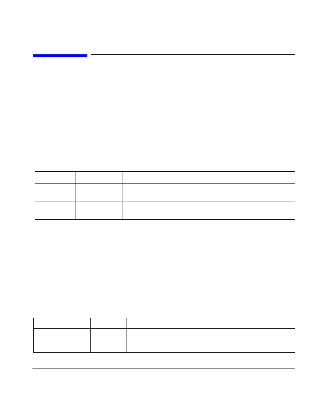
configuring X Windows on HP-UX (other graphics cards)
input devices
keyboards
supported keyboard drivers
The following is a list of supported keyboard drivers:
keyboard
supported keyboard options
The following is a list of keyboard options that are supported by HP.
Table 3-5
Options Value Description
AutoRepeat Integer Set the keyboard auto repeat parameters. Not all platforms
implement this.
input devices
Xleds Integer … Specify which keyboard LEDs can be user-controlled (for
example, with xset(1)).
pointers
supported pointer drivers
The following is a list of supported pointer drivers:
mouse
supported pointer options
The following is a list of pointer options that are supported by HP.
Table 3-6
Options V alue Description
Protocol String Values may only be “PS/2”
Device String The value may only be “/dev/hid/mouse_000”
Chapter 3 65
Page 68
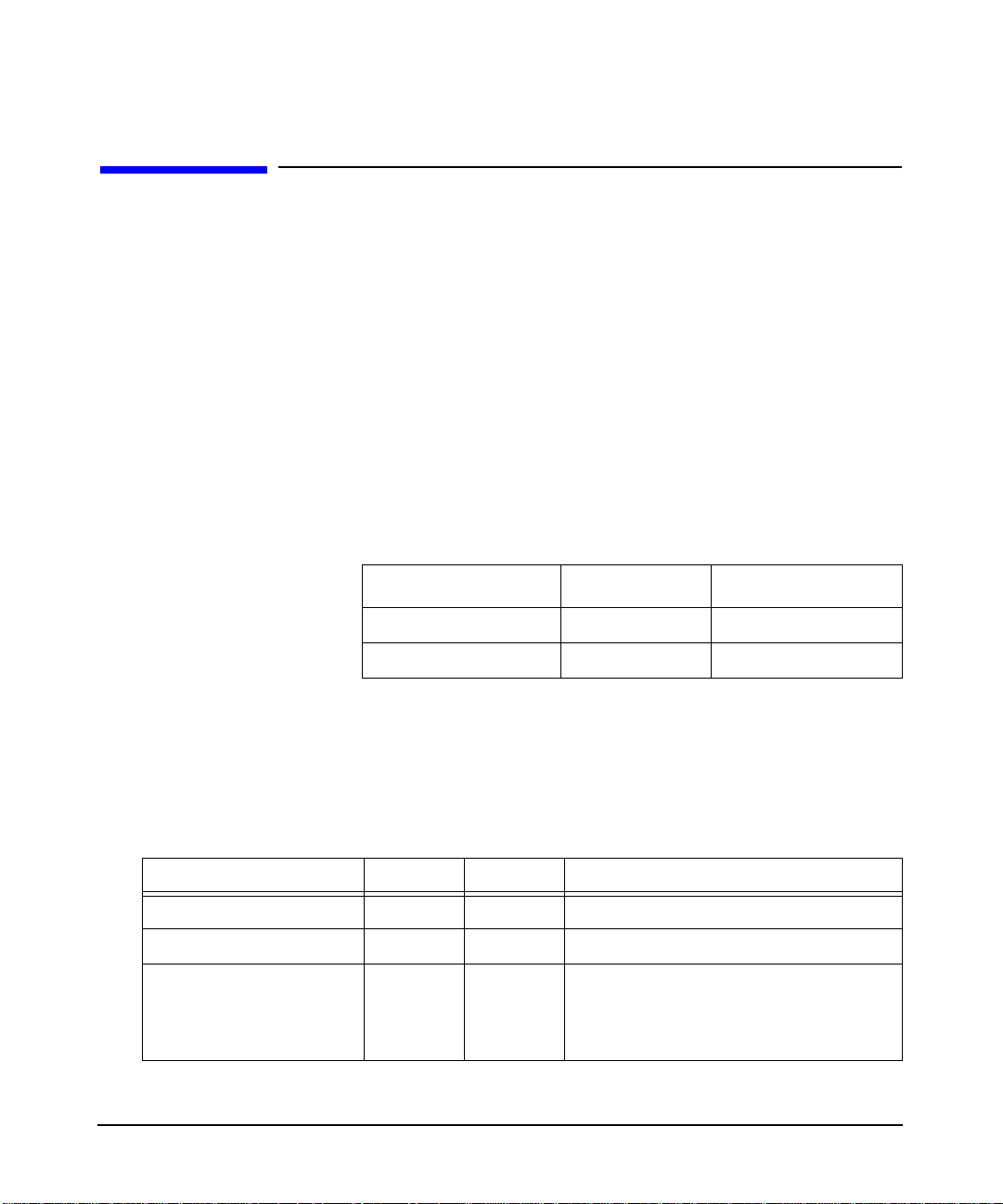
configuring X Windows on HP-UX (other graphics cards)
output devices
output devices
hp Fire™ GL-UX device-dependent information
HP Fire GL-UX provides 8 overlay planes, 48 image planes, a 24-bit Z
buffer, 4 8-bit per channel hardware colormaps and 1 10-bit per channel
hardware colormap for use in gamma correction. This device provides 2D
hardware acceleration for most operations as well as 3D acceleration for
lighting, shading and texture mapping.
supported visuals
HP Fire GL-UX supports the following visuals:
Table 3-7
Class Depth Layer
PseudoColor 8 Overlay
TrueColor 24 Image
Both the PseudoColor and TrueColor visuals are enabled by default. See
the section “Supported Device Options” below for instructions on
changing the default visual and/or disabling overlay visuals.
supported device options
Table 3-8
Options Value Default Description
enableDVI Boolean False Enable DVI connector.
Qbs Boolean False Enable quad-buffered stereo mode.
CountTransInOvlyVis Boolean True When set to false, causes the X Server to
reserve the transparent pixel index in all
PseudoColor overlay colormaps, thus
reporting only 255 available entries.
Chapter 366
Page 69
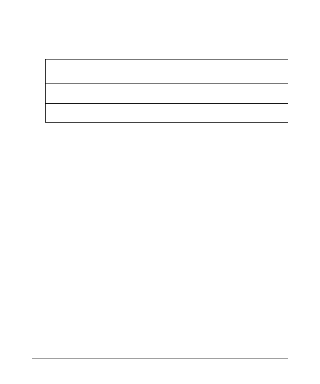
configuring X Windows on HP-UX (other graphics cards)
Table 3-8 (Continued)
PHOOGL Vi suals Boolean False Modify the GLX visual list so that legacy
3-D applications are more likely to
choose an appropriate OpenGL visual.
output devices
TransparentIndex0 Boolean False
DefaultVisualTrueColor Boolean False
These options are enabled by adding a line to the
/etc/X11/XF86Config file in the Device section. For example:
Option "Overlay" "True"
Note that both the option name and option value must be enclosed in
quotation marks. Options that do not take parameters require only one
value, the option name. For example:
Option "TransparentIndex0"
supported monitor configurations
The following table documents supported display resolution and refresh
rate for the HP Fire GL-UX. Check your monitor specification to
determine if the monitor supports any or all of these resolutions.
Make the overlay transparent pixel index 0
instead of 255.
Use TrueColor as the default visual
instead of PseudoColor.
Chapter 3 67
Page 70

configuring X Windows on HP-UX (other graphics cards)
output devices
Table 3-9
Resolution (HxV) Frequency (Hz) Description
1024x768 75 VESA Standard
1024x768 85 VESA Standard
1280x1024 60 VESA Standard
1280x1024 75 VESA Standard
1280x1024 85 VESA Standard
1600x1024 75 24" monitor
1600x1024 85 24” monitor
1600x1200 75 VESA Standard
1600x1200 85 VESA Standard
1920x1080 75 24" monitor
1920x1080 85 24" monitor
1920x1200 75 24" monitor
1920x1200 85 24" monitor
ATI FireGL™ X1/T2/X3 device-dependent information
The ATI FireGL family graphics cards provides 8 or 24 overlay planes, 48
image planes, a 24-bit Z buffer, an 8 bit stencil buffer, and 16 bits per
channel (RGBA) of accumulation buffer. There is one hardware colormap
for the overlay planes and one hardware colormap in the image planes
for gamma correction. These devices provide 2D hardware acceleration
for most operations as well as 3D acceleration for lighting, shading and
texture mapping.
supported visuals
ATI FireGL cards support the following visuals:
Class Depth Layer
PseudoColor 8 Overlay
Chapter 368
Page 71
configuring X Windows on HP-UX (other graphics cards)
output devices
Class Depth Layer
TrueColor (optional) 24 Overlay
TrueColor 24 Image
The depth 8 PseudoColor and TrueColor visuals are enabled by default.
See the section “Supported Device Options” that follows for instructions
on changing the default visual and/or disabling overlay visuals.
supported device options
The following screen options can be set with SAM from the Modify
Screen Options action in the X server Configuration Menu..
Chapter 3 69
Page 72
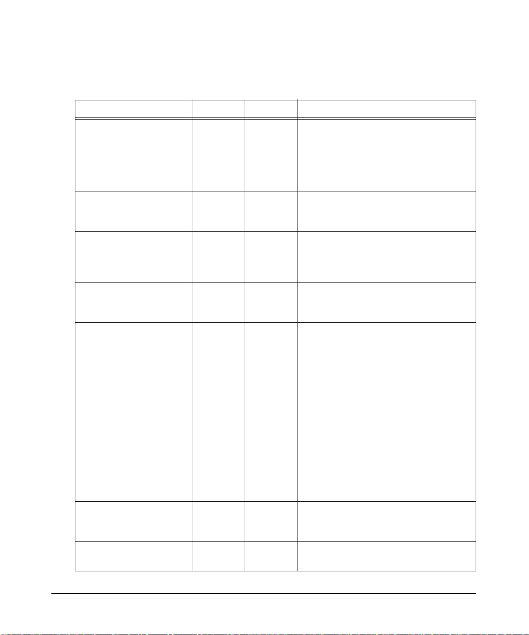
configuring X Windows on HP-UX (other graphics cards)
output devices
Table 3-10
Screen Option Type Default Description
AccelerateIndirectRender
ing
BackingStore Boolean False Enables support for backing store and
DefaultVisualTrueColor Boolean False Use a TrueColor visual as the default
EnableOpaqueOverlayVi
sual
FSAAScale
Boolean
Boolean False Enable a depth 8 PseudoColor visual in
Integer
True
Not Set
Controls whether indirect OpenGL
contexts utilize hardware acceleration or
use the HP VMD software driver.
Applications that require large or
numerous GLX pixmaps may require
that this option be set to false.
save unders as requested by
applications.
visual. If TrueColorOverlay is also
enabled, the default visual will be
TrueColor visual in the Overlay planes.
the overlay planes that does not reserve
index 255 for transparency..
Specifies the maximum number of samples per pixel for OpenGL Multisample
rendering. (Full Scene AntiAliasing)
Permissible values are 2, 4, or 6. The
FSAA buffers are reserved at X server
startup. All buffers (front, back, depth,
FSAA) are allocated from the first
128MB of framebuffer memory. If there
is insufficient memory for the requested
FSAAScale at a given screen resolution,
the server will attempt to allocate a
lower scale factor.
Overlay
Stereo
TrueColorOverlay
Boolean
Boolean
Boolean
True
False
False
Disable overlay visuals completely.
Enable visuals for OpenGL Stereo
rendering. Allocates separate left and
right sets of color buffers.
Enable a TrueColor visual in the overlay
planes.
Chapter 370
Page 73

configuring X Windows on HP-UX (other graphics cards)
output devices
supported monitor configurations
All FireGL cards support multiple monitors. The FireGL X1 and X3 have
dual DVI-I connectors, which will drive either digital or analog monitors .
The FireGL T2 has one DVI-I and one VGA connector. When using a
single monitor , the monitor can be attached to either connector. Monitors
should be connected and powered up prior to system boot to ensure the
system can read available DDC information and select optimum video
timings.
Multiple monitors are supported in a Single Logical Screen (SLS)
configuration. The maximum SLS screen width is 2560 for the X1 and
T2 and 3840 for the X3. See the “using SAM to configure X Windows”
section for details on configuring SLS with SAM.
Chapter 3 71
Page 74

configuring X Windows on HP-UX (other graphics cards)
hp Fire GL-UX configuration hints
hp Fire GL-UX configuration hints
overlay visuals and overlay transparency
HP Fire GL-UX devices have one visual in the overlay planes, depth-8
PseudoColor. To allow applications to determine which visuals are in the
overlay planes, overlay visuals are listed in the
"SERVER_OVERLAY_VISUALS" property attached to the root window.
The default overlay visual has a transparent type of "1" (TransparentPixel).
If you need an overlay colormap that supports transparency, create the
colormap using the visual that has transparency in its
SERVER_OVERLAY_VISUALS property. To look at the contents of this
property, you would use code similar to the following:
{
typedef struct {
VisualID overlayVisualID;
Card32 transparentType;
/* None, TransparentPixel, TransparentMask */
Card32 value;
/* Either pixel value or pixel mask */
Card32 layer;
} OverlayVisualPropertyRec;
OverlayVisualPropertyRec *pOverlayVisuals, *pOVis;
XVisualInfo getVis;
XVisualInfo *pVisuals;
Atom overlayVisualsAtom, actualType;
...
/* Get the visuals for this screen and allocate. */
getVis.screen = screen;
pVisuals = XGetVisualInfo(display, VisualScreenMask,
pOverlayVisuals = (OverlayVisualPropertyRec *)
&getVis, &nVisuals);
malloc ( (size_t)nVisuals *
sizeof(OverlayVisualPropertyRec) );
/*
** Get the overlay visual information for this screen. Obtain
** this information from the SERVER_OVERLAY_VISUALS property.
*/
overlayVisualsAtom = XInternAtom(display,"SERVER_OVERLAY_VISUALS",
if (overlayVisualsAtom != None)
True);
Chapter 372
Page 75

configuring X Windows on HP-UX (other graphics cards)
hp Fire GL-UX configuration hints
{
/* Since the Atom exists, request the property's contents. */
bytesAfter = 0;
numLongs = (nVisuals * sizeof(OverlayVisualPropertyRec) + 3 )
XGetWindowProperty(display, RootWindow(display, screen),
if (bytesAfter != 0 ) {/* Serious Failure Here */} ;
/* Loop through the pOverlayVisuals array. */
...
nOVisuals = numLongs/sizeof(OverlayVisualPropertyRec);
pOVis = pOverlayVisuals;
while (--nOVisuals >= 0)
{if ( pOVis->transparentType == TransparentPixel )
pOVis++;
}
XFree(pOverlayVisuals);
/*
**There might be some additional checking of the found
**transparent overlay visuals wanted; e.g., for depth.
*/
}
XFree(pVisuals);
/ 4;
overlayVisualsAtom, 0, numLongs, False,
AnyPropertyType, &actualType, &actualFormat,
&numLongs, &bytesAfter, &pOverlayVisuals);
{/*
**Found a transparent overlay visual,
**set ident. aside.
*/
};
}
This program segment is not complete; however, its main purpose is to
give an idea of how to find an overlay visual having transparency.
When the overlay planes are enabled, one colormap entry in PseudoColor
colormaps is not available for use by clients. The server handles this
entry in one of two ways depending upon the setting of the "CountTransInOvlyVis" device option. If the option is not set, the server will
report that 256 colormap entries are available for allocation in the
PseudoColor visual. However, the transparent pixel will always remain
transparent. The image layer will be visible wherever this pixel value is
rendered in the overlay planes. Hence, applications should not render
using this pixel unless transparency is desired.
Chapter 3 73
Page 76

configuring X Windows on HP-UX (other graphics cards)
hp Fire GL-UX configuration hints
This may cause problems with some applications. Setting "CountTransInOvlyVis" causes the server to reserve the transparent pixel index. In
this case, the server reports that 255 colormap entries are available for
allocation in the PseudoColor visual. This option may be useful to applications that depend on having 256 colormap entries available in depth 8
PseudoColor visuals. The transparent index value is configurable
through the "TransparentIndex0" device option. Setting this option will
change the transparent pixel value to 0 from the default of 255. This
option may be useful to applications that depend on the transparent
pixel value being 0.
HP Fire GL-UX Colormaps Hints
HP Fire GL-UX devices have a total of 5 hardware colormaps. One colormap is reserved for gamma correction and is not directly available to X
clients. The remaining colormaps are available for clients to use. When
the default visual is in the overlay planes, one of the four available hardware colormaps is reserved for the default colormap. This ensures that
clients using the default colormap never encounter technicolor.
The HP Fire GL-UX driver reports on the installation status of a total of
5 colormaps via the XListInstalledColormaps() API. Four of these correspond to the actual state of the hardware color tables used with PseudoColor visuals. Colormaps are installed in these hardware LUTs in
first-in, first-out order. The driver also keeps track of the last TrueColor
colormap installed via XInstallColormap() and includes this information
whenever queried. By definition, all TrueColor colormaps are always
installed.
Chapter 374
Page 77

configuring X Windows on HP-UX (other graphics cards)
hp Fire GL-UX configuration hints
system requirements
hardware compatibility table
This table lists graphics cards that are support on a system and which
OS is required:
Graphics Device Supported Systems
HP Fire GL-UX C3650, C3700, J6700 HP-UX 11.0 and 11.11
monitor compatibility Most multi-sync monitors are compatible with
the graphics cards in this release of the X Server. All current monitors
from HP are compatible.
compatibility matrix with previous releases The following table
illustrates differences between the graphics devices of previous HP
releases and the graphics device of this release.
Feature Visualize fxe
Overlay Planes 8 8 8/8
Overlay LUTs 2 2 4 (shared)
Image Planes 32 32 32
Image LUTs 2 2 4 (shared)
Visualize
fx5/fx10
HP Fire
GL-UX
1 Gamma
Per-pixel Attributes Yes Yes Yes
Required Operating
System
ATI FireGL
X1/X3/T2-128
8/8 or 24
Infinite
32
1
No
Default Visual 8I-O 8I-O 8I-O
Overlay Transparency Yes Yes Yes
Gamma Correction Yes Yes Yes
Buffer swap method Register write Register write Register write
Stereo support No Yes (external
sync and
glasses)
Yes (glasses)
8I-O
Yes
Yes
Copy Swap
Yes: X1, X3
No: T2
Chapter 3 75
Page 78

configuring X Windows on HP-UX (other graphics cards)
hp Fire GL-UX configuration hints
Feature Visualize fxe
Clip rectangles 4 4 1
Clip plane Yes Yes Yes
Hardware byte swapping Yes Yes Yes
Video conversion No Yes Yes
1920x1200 @ 76 Hz No Yes Yes
1600x1200 @ 85 Hz No Yes Yes
1280x1024 @ 85 Hz No Yes Yes
1024x768 @ 85 Hz No Yes Yes
Hardware multi display No No No
PCI 2X 4X 4X
AGP No No No
Visualize
fx5/fx10
HP Fire
GL-UX
miscellaneous
ATI FireGL
X1/X3/T2-128
1
Yes
Yes
Yes
Yes
Yes
Yes
Yes
Yes (Max of 2)
No
3.0 (8X)
fonts
The X Server can obtain fonts from directories or font servers. Setting up
a font server or making a directory a font directory is beyond the scope of
this document. The font path can be loaded via the –fp option from the
command line or from the XF86Config file. The latter is the preferred
method. The default font path is: /usr/lib/X11/fonts/misc. See section “The XF86Config File: Files Section” regarding the FontPath. The
following font directories are delivered with the system and may be
added to the font path. Applications may install their own fonts. The
application font path can be added to the FontPath as necessary.
/usr/lib/X11/fonts/misc/
/usr/lib/X11/fonts/hp_kana8/
/usr/lib/X11/fonts/hp_roman8/75dpi/
/usr/lib/X11/fonts/iso_8859.1/100dpi/
Chapter 376
Page 79

configuring X Windows on HP-UX (other graphics cards)
hp Fire GL-UX configuration hints
/usr/lib/X11/fonts/iso_8859.1/75dpi/
/usr/lib/X11/fonts/hp_chinese_s/75dpi/
/usr/lib/X11/fonts/hp_chinese_t/75dpi/
/usr/lib/X11/fonts/hp_korean/75dpi/
/usr/lib/X11/fonts/hp_japanese/100dpi/
/usr/lib/X11/fonts/iso_8859.2/75dpi/
/usr/lib/X11/fonts/iso_8859.5/75dpi/
/usr/lib/X11/fonts/iso_8859.6/75dpi/
/usr/lib/X11/fonts/iso_8859.7/75dpi/
/usr/lib/X11/fonts/iso_8859.8/75dpi/
/usr/lib/X11/fonts/iso_8859.9/75dpi/
/usr/lib/X11/fonts/iso_8859.15/75dpi/
files
The X Server makes use of various files on the system during normal
operation. The section lists the default location of the files and gives a
brief description of what they do.
File Description
/etc/X11/XF86Config The configuration file. Xf86 uses this
file to configure itself during
initialization.
/etc/X11/rgb The color database.
/etc/Xn.hosts Initial access control list for display n.
/var/X11/Xserver/logs/Xf86.n.log The log file, where n is the display number.
Chapter 3 77
Page 80

configuring X Windows on HP-UX (other graphics cards)
ATI FireGL X1/T2/X3 configuration hints
ATI FireGL X1/T2/X3 configuration hints
overlay visuals and overlay transparency
FireGL devices support both depth 8 PseudoColor and depth 24
TrueColor overlay visuals. The depth 8 PseudoColor visuals with
transparency are enabled by default for compatibility with previous
devices. An opaque depth 8 PseudoColor visual can be enabled by setting
the EnableOpaqueOverlayVisual screen option described in the previous
section. This option is useful for applications that require allocation of
all 256 entries in the colormap with no index mapping to transparency.
The SERVER_OVERLAY_VISUALS property is attached to the root
window. The default overlay visual has a transparent type of "1"
(TransparentPixel). If you need an overlay colormap that supports
transparency, create the colormap using the visual that has
transparency in its SERVER_OVERLAY_VISUALS property. See the
Fire GL-UX configuration hints section for a code fragment .
The depth 24 TrueColor overlay visual is enabled by setting the
TrueColorOverlay screen option described in the previous section. To
make the TrueColor overlay visual the default, also set the
DefaultVisualTrueColor screen option. The
SERVER_OVERLAY_VISUALS property will not report this visual.
Overlay visuals are disabled completely when a Single Logical Screen
configuration is enabled, or when using a display with at width of greater
than 1920 pixels.
colormaps
FireGL devices have a colormap per window for windows created in the
overlay visuals. There is a single colormap in the image planes. The
image colormap is reserved for gamma correction and is not directly
available to X clients.
Chapter 378
Page 81

configuring X Windows on HP-UX (other graphics cards)
ATI FireGL X1/T2/X3 configuration hints
gamma correction
Gamma correction can be applied to windows in the image planes
explicitly with the gamma tool (/opt/graphics/common/bin/gamma) or
implicitly by running a direct rendering OpenGL application. If no
default gamma has been set with the gamma tool, the OpenGL libraries
will apply a gamma of 1.7 when starting an OpenGL application.
ATI FireGL X1, T2, and X3 devices behave differently than HP Visualize
or HP Fire GL-UX devices because ATI FireGL devices have one gamma
colormap. Previous devices allowed at least one OpenGL window to have
gamma applied without affecting other windows in the image planes.
FireGL devices will apply the OpenGL gamma value to all windows in
the image planes. This is most noticeable when the default visual
resides in the image planes. In this case, the entire desktop can become
overly bright when an OpenGL application starts.
There are two ways to avoid this behavior.
• Set a screen default gamma to a value other than 1.0 using the
gamma tool. This solution will completely eliminate the brightening
of all windows when an OpenGL application starts because the
screen default gamma value takes precedence over the default
OpenGL gamma value. OpenGL applications may appear dimmer
than expected using this solution.
• Enable the TrueColorOverlay screen option in addition to
DefaultVisualTrueColor. With the default TrueColor visual in the
overlay planes, the desktop and most Xlib applications will not be
affected by direct rendering OpenGL windows, as OpenGL windows
always reside in the image planes. Gamma correction can only be
applied to TrueColor windows in the image planes. In addition, this
solution is not available with Single Logical Screen configurations or
when using displays with at width greater than 1920 because overlay
planes are not available in these configurations.
Chapter 3 79
Page 82

4 X Windows configuration details
This chapter discusses several details concerning the configuration of X
hosts, colormaps, mouse and keyboard.
Chapter 4 79
Page 83

X Windows configuration details
making an x*.hosts file
making an x*.hosts file
The /etc/X0.hosts file is an ASCII text file containing the hostnames of
each remote host permitted to access your local server.
• If you are running as a stand-alone system, you must have your
• If you are part of a network, the other system names must be
The syntax is as follows:
<host>
<host>
<host>
For example, if you are hpaaaaa, and regularly ran clients on hpccccc,
and hpddddd, you would want the following lines.
hpaaaaa
hpccccc
hpddddd
system’s name in this file.
included.
Note that aliases work as well as hostnames, provided they are valid,
that is, commonly known across the network.
using an /etc/hosts file
This file need not be present if your system is configured to query a
nameserver.
The /etc/hosts file is an ASCII text file containing a list of all the host
names and internet addresses known to your system, including your own
system.
If your system is not connected to a network, use the loopback address
(127.0.0.1) and the hostname unknown:
127.0.0.1 unknown
For a local system to access a remote host:
• The address and hostname of the remote host must be listed in the
local system’s /etc/hosts file.
Chapter 480
Page 84

X Windows configuration details
making an x*.hosts file
• The user must have a valid login (username and password) and home
directory on the remote host.
stopping the X Window system
After stopping all application programs, stop the window system by
holding down the
key. This stops the display server, and with it the window system.
Ctrl and Shift keys, and then pressing the Pause/Break
customizing the mouse and keyboard
This section describes various customizations that can modify the
default keyboard and mouse behavior.
changing mouse button actions
The xmodmap utility can be used to change mouse button mappings. The
syntax for changing mouse button mappings with xmodmap is:
xmodmap {-e ìpointer = {default | number [number...]}î | -pp}
where:
-e
Specifies a remapping expression. Valid expressions are covered in
“Customizing Keyboard Input”.
default
Set mouse keys back to default bindings.
number
Specifies a list of button numbers to map the mouse keys to. The order of
the numbers refers to the original button mapping.
pp
Print the current pointer mapping.
For example, to reverse the positions of buttons 1 and 3 for left-handed
mapping:
xmodmap -e “pointer = 3 2 1" (2-button mouse)
xmodmap -e “pointer = 3 2 1 5 4" (3-button mouse)
To establish OSF/Motif-standard button mapping:
xmodmap -e “pointer = 1 3 2" 2-button mouse
Chapter 4 81
Page 85

X Windows configuration details
making an x*.hosts file
xmodmap -e “pointer = 1 3 2 4 5" 3-button mouse
modifying modifier key bindings with xmodmap
To change the meaning of a particular key for a particular X11 session,
or to initialize the X Server with a completely different set of key
mappings, use the xmodmap client.
The syntax for xmodmap is as follows: xmodmap <options> [<filename>]
where <options> are:
-display <host>:<display>
Specifies the host, display number, and screen to use.
-help
Displays a brief description of xmodmap options.
-grammar
Displays a brief description of the syntax for modification expressions.
-verbose
Prints log information as xmodmap executes.
-quiet
Turns off verbose logging. This is the default.
-n
Lists changes to key mappings without actually making those changes.
-e <expression>
Specifies a remapping expression to be executed.
-pm, -p
Prints the current modifier map to the standard output. This is the
default.
-pk
Prints the current keymap table to the standard output.
-pp
Print the current pointer map to the standard output.
- (dash)
Specifies that the standard input should be used for the input file.
<filename>
Specifies a particular key mapping file to be used.
Chapter 482
Page 86
Table 4-1
X Windows configuration details
making an x*.hosts file
specifying key remapping expressions
Whether you remap a single key “on the fly” with a command-line entry
or install an entire new keyboard map file, you must use valid
expressions in your specification, one expression for each remapping.
A valid expression is any one of the following:
To do this . . . Use this expression . . .
Assign a key symbol to a keycode keycode <keycode> = <keysym>
Replace a key symbol expression with another keysym <keysym> = <keysym>
Clear all keys associated with a modifier key clear<modifier>
Add a key symbol to a modifier add <modifier>= <keysym>
Remove a key symbol from a modifier remove <modifier> = <keysym>
keycode
Refers to the numerical value that uniquely identifies each key on a
keyboard. Values may be in decimal, octal, or hexadecimal.
keysym
Refers to the character symbol name associated with a keycode; for
example, KP_Add.
<modifier >
Specifies one of the eight modifier names: Shift, Control, Lock, Mod1,
Mod2, Mod3, Mod4, and Mod5.
On Hewlett-Packard keyboards , the lock modifier is set to the
Caps key.
However, any of the modifiers can be associated with any valid key
symbol. Additionally, you can associate more than one key symbol with a
modifier (such as Lock = Shift_R and Lock = Shift_L), and you
can associate more than one modifier with a key symbol (for example,
Control = Caps_Lock and Lock = Caps_Lock).
For example, on a PC-style keyboard, you can press
case "d",
Shift Alt D to print still something else.
Shift D to print a capital "D", Alt D to print something else, and
D to print a lower
The xmodmap client gives you the power to change the meaning of any
key at any time or to install a whole new key map for your keyboard.
Chapter 4 83
Page 87

X Windows configuration details
making an x*.hosts file
examples
Suppose you frequently press the
moments. You could remove the
swap it for the
f1 key, then map the f1 key to the lock modifier. Do this by
Caps key at the most inopportune
Caps lock key from the lock modifier,
creating a little swapper file that contains the following lines:
!This file swaps the [Caps] key with the [F1] key.
remove Lock = Caps_Lock
keysym Caps_Lock = F1
keysym F1 = Caps_Lock
add Lock = Caps_Lock
Note the use of the ! in the file to start a comment line. To put your
"swapper" file into effect, enter the following on the command line:
xmodmap swapper
If you use such a swapper file, you should probably have an unswapper
file. The following file enables you to swap back to the original keyboard
mapping without having to exit X11:
!This file unswaps the [F1] key with the [Caps] key.
remove Lock = Caps_Lock
keycode 88 = F1
keycode 55 = Caps_Lock
add Lock = Caps_Lock
Note the use of the hexadecimal values to reinitialize the keycodes to the
proper key symbols. You put your “unswapper” file into effect by entering
the following command line:
xmodmap unswapper
On a larger scale, you can change your current keyboard to a Dvorak
keyboard by creating a file with the appropriate keyboard mappings.
xmodmap .keymap
printing a key map
The -pk option prints a list of the key mappings for the current keyboard.
xmodmap -pk
The list contains the keycode and up to four 2-part columns. The first
column contains unmodified key values, the second column contains
shifted key values, the third column contains meta (
Extend Char/Alt) key
Chapter 484
Page 88

X Windows configuration details
making an x*.hosts file
values, and the fourth column contains shifted meta key values. Each
column is in two parts: hexadecimal key symbol value, and key symbol
name.
Chapter 4 85
Page 89

X Windows configuration details
making an x*.hosts file
Chapter 486
 Loading...