

Page 1

HP SCSI Disk Drives
User Manual
C6388B Desktop
C6389A Rack-Ready
C6390A Desktop
C6391A Rack-Ready
C6394B Desktop
C6395A Rack-Ready
C6396A Desktop
C6397A Rack-Ready
English
Japanese
Page 2

Page 3
HP C6388B
HP C6389A
HP C6390A
HP C6391A
HP C6394B
HP C6395A
HP C6396A
HP C6397A
User Manual
SCSI Disk Drives
Desktop & Rack-Ready Models
Page 4

ii
Page 5

Warranty
HP offers a two-year warranty for models C6388B, C6389A, C6390A, C6391A,
C6394B, C6395A, C6396A, and C63 97A.
1. HP warrants HP hardware, accessories, and supplies against defects in materials and
workmanship for the period specified above. If HP receives notice of such defects
during the warranty period, HP will, at its op tio n, eith e r rep ai r or repla c e prod uc ts tha t
prove to be defective. Replacement products may be either new or like-new.
2. HP warrants that HP software will not fail to execute its programming instructions,
for the period specified above, due to defects in material and workman s hip when
properly installed and used. If HP receives notice of such defects during the warranty
period, HP will replace software media that does not execute its programming
instructions due to such defects.
3. HP does not warrant that the operation of HP products will be uninterrupted or error
free. If HP is unable, within a reasonable time, to repair or replace any product to a
condition as warranted, customer will be entitle d to a refund o f the purchase pri ce upon
prompt return of the product.
4. HP products may contain remanufactured parts equivalent to new in performance or
may have been subject to incidental use.
5. The warranty period begins on the date of delivery or on the date of installation if
installed by HP. I f customer schedules or delays HP installation more than 30 days
after delivery, warranty begins on the 31st day from delivery.
6. Warranty does not apply to defects resulting from (a) imp roper or inadequate
maintenance or calibration; (b) software, interfacing, parts or supplies not supplied by
HP; (c) unauthorized modificatio n or misuse; (d) operation outside of the published
environmental specifications for the product; or (e) improper site preparation or
maintenance.
7. TO THE EXTENT ALLOWED BY LOCAL LAW, THE ABOVE WARRANTIES
ARE EXCLUSIVE AND NO OTHER WARRANTY OR CONDITION, WHETHER
WRITTEN OR ORAL, IS EXPRESSED OR IMPLIED AND HP SPECIFICALLY
DISCLAIMS ANY IMPLIED WARRANTIES OR CONDITIONS OF
MERCHANTABILITY, SATISFACTORY QUALITY, AND FITNESS FOR A
PARTICULAR PURPOSE.
8. HP will be liable for damage to tangible property per incident up to the greater of
$300,000 or the actual amount paid for the product that is the subject of the claim, and
for damages for bodily injury or death, to the extent that all such damages are
determined by a court of comp etent jurisdiction to have been di rectly caused by a
defective HP product.
iii
Page 6

9. TO THE EXTENT ALLOWED BY LOCAL LAW, THE REMEDIES IN THIS
WARRANTY STATEMENT ARE CUSTOMER’S SOLE AND EXCLUSIVE
REMEDIES. EXCEPT AS INDICATED ABOVE, IN NO EVENT W ILL HP OR ITS
SUPPLIERS BE LIABLE FOR LOSS OF DATA OR FOR DIRECT, SPECIAL,
INCIDENTAL, CONSEQUENTIAL (INCLUDING LOST PROFIT OR DATA), OR
OTHER DAMAGE, WHETHER BASED IN CONTRACT, TORT, OR
OTHERWISE.
10. FOR CONSUMER TRANSACTIONS IN AUSTRALIA AND NEW ZEALAND:
THE WARRANTY TERMS CONTAINED IN THIS STATEMENT, EXCEPT TO
THE EXTENT LAWFULLY PERMITTED, DO NOT EXCLUDE, RESTRICT, OR
MODIFY AND ARE IN ADDITION TO THE MANDATORY STATUTORY
RIGHTS APPLICABLE TO THE SALE OF THIS PRODUCT TO YOU.
iv
Page 7

Reproduction, adaptation, o r translation wi thout prior written permission is prohibit ed,
except as allowed under the copyright laws.
© Copyright 1998
Hewlett-Packard Company
All rights reserved
Publication number
C6388-90001
Applicable Products:
HP C6388B
HP C6389A
HP C6390A
HP C6391A
HP C6394B
HP C6395A
HP C6396A
HP C6397A
Safety Considerations
Prior to the installation and use of this product, review all safety markings and
instructions.
Instruction Manual Symbol. If the
!
product is marked with this symbol,
refer to the product manuals to
protect the product from damage .
WARNING
CAUTION
Do not proceed beyond a WARNING or CAUTION notice un til you understan d the
hazard and take appropriate precautions.
Denotes a hazard that can cause
injury
Denotes a hazard that can damage
equipment or data.
v
Page 8

Servicing
Any servicing, adjustment, maintenance or repair must be performed only by
authorized service-trained personnel.
Grounding
This product provides a protective grounding termin al. There must be an uninte rrupted
safety ground from the main power source to the product’s input wiring terminals,
power cord, or supplied power cord set. Whenever it is likely that the protection has
been impaired, di sconnect the power cord until the ground has been restored.
Servicing
Any servicing, adjustment, maintenance, or repair must be performed by HP
authorized and trained service personnel.
Support
For online produ c t support information 24 ho urs / d a y an d 7 da ys /w e e k:
World Wide Web:
http://www.hp.com
Patches can be downloaded from Hewlett-Packard’s Electroni c Support Center at:
http://us-support.external.hp.com/
America Online:
Keyword: HP
vi
CompuServe:
GO: HP
Page 9

Regulatory Information
USA
Federal Communications Commission (FCC)
Note: This equipment has been tested and found to comply with the limits for a
Class B digital device, pursuant to part 15 of the FCC Ru les. These limits are
designed to provide reasonable protection against harmful interference in a
residential installation. This equipment gen e rates, uses, and can radiate radio
frequency energy and, if not installed and used in accordance with the
instructions, may cause harmful interference to radio communications.
However, there is no guarantee that interference will not occur in a particular
installation. If this equipment does cause harmful interference to radio or
television reception, which can be determined by turning the equipment off
and on, the user is encouraged to try to correct the interference by one or more
of the following measures:
• Reorient or relocate the receiving antenna
• Increase the separation between the equipment and receiver
• Connect the equipment to an outlet on a another circuit
• Consult the dealer or an experienced radio/TV technician for help
Compliance with these regulations requires the use of shielded cables.
Changes or modifications to the equipment not expressly approved by
Hewlett-Packard could void the user’s authority to operate it .
Canada
Canadian Department of Communications (DOC)
This digital apparatus does not exceed the Class B limits for radio noise
emissions from digital apparatus as set out in the Radio Interference
Requirements of the Canadian Department of Communications, ICES-003.
Compliance with these regulations requires the use of shielded cables.
vii
Page 10
Europe
Declaration of Conformity
according to ISO/IEC Guide 22 and EN45014
Manufacturer’s Name: Hewlett-Packard
Manufacturer’s Address:
Declares that the product
Product Name: External Desktop Mass Stor ag e Devi ces
Product Type: Disk Drives
Model Numbers:
Product Options: All
Conforms to the following Produc t Specifications:
Safety: IEC 950:1991+A1+A2+A3+A4
333 Logue Avenue
Mountain View, CA 94043 U.S.A.
C6388B, C6389A, C6390A, C6391A, C6394B, C6395A, C6396A,
C6397A
EN 60950:1992+A1+A2+A3+A4
viii
EMC: CISPR 22:1993 / EN 55022:1994 - Class B
Supplementary Information:
The product herewith complies with the requirements of the Low Voltage Directive 73/23/EEC and
93/68/EEC and the EMC Directive 89/336/EEC and 92/31/EEC and 93/68/EEC and carries the
CE Marking, accordingly.
(1)
The product was tested in a typical configuration with a Hewlett-Packard computer system.
Mountain View, CA, U.S.A. July 1, 1998
Location Date Cal Maclean, Business Manager
Only for Regulatory Compliance Information:
European Contact: Your local Hewlett-Packard Sales & Service Office or Hewlett-Packard
GmbH, Department HQ-TRE / Standards Europe, Herrenberger Strasse 130,
D-71034 Böeblingen (Fax: +49-7031-14-3143).
EN 50082-1:1992
IEC 801-2:1991 / prEN 55024-2:1992 - 4kV CD, 8kV AD
IEC 801-3:1984 / prEN 55024-3:1991 - 3V/m
IEC 801-4:1988 / prEN 50024-4:1992 - 1kV power lines
FCC Title 47 CFR, Part 15, Class B
(1)
- 0.5kV signal lines
(1)
Page 11
Japan
VCCI Class B ITE
English Translation
This equipment is in the Class B category information technology equipment
based on the rules of Voluntary Control Council for Interference by
Information Technology Equipment (VCCI). Although aimed for residential
area operation, radio interference may be caused when used near a radio or
TV receiver.
Read the instructions for correct operation.
ix
Page 12

x
Page 13

Table of Contents
1. Overview ................................................................................................1-1
2. Disk Installation ....................................................................................2-1
1. Contents of the Kit for Desktop Models .............................................2-1
2. Environment ......................................................................................2-2
3. Check Your SCSI Cable ....................................................................2-2
4. Operating System Compatibility ............................................. ..... ..... .2-2
5. Set the SCSI ID Selector Switch .......................................................2-3
6. Mount Your Drive Vertically (Optional) ..............................................2-4
7. Connect the SCSI Cable ...................................................................2-6
8. Connect the Power Cable ..................................................................2-7
9. Power On the Unit .............................................................................2-8
10. Configuring the Drive .........................................................................2-8
11. Rack Mounting ................................... ..... ................................ ..... ......2-8
ENGLISH
Appendix A: Specifications ................................................................... A-1
Appendix B: Rack-Ready Modules ........................................................B-1
Appendix C: Cable Accessories ............................................................ C-1
Page 14

Page 15

Overview
1
ENGLISH
HP Desktop Disk Drive
HP’s Desktop and Rack-Ready Disk Drives provide a wide range of storage
flexibility and reliability:
• HP offers a boot capable disk storage solution beginning with the HP
C6388B Desktop 4GB drive to the HP C6396A Desktop 9GB disk drive.
• When space is at a premium, all desktop versions can be vertically mounted
and ship with a vertical mount stand.
• The desktop and rack-ready drives are highly reliable with a MTBF (Mean
Time Between Failure) minimum rating of one million hours for
mechanisms. (Actual failure rates will vary from unit to unit. See Appendix
A.)
• This series of HP drives is backed by a two-year warranty.
Note *Some versions of HP-UX do not support bootable disks. See Appendix A.
Overview 1-1
Page 16

1-2 Overview
Page 17

Disk Installation
1. Contents of the Kit for Desktop Models
Ensure that the kit contains the following parts:
2
ENGLISH
q Desktop Disk Drive
q Rubber Feet for Stand
q Stand for Vertical Mounting
q Power Cord
q User Manual
Figure 2-1 Kit Contents
Disk Installation 2-1
Page 18

Note HP rack-ready models C6389A, C6391A, C6395A, and C6397A do not
require rubber feet or a stand.
Rack-Ready Drives
The HP C4318B 3U-4Bay Rack Mount Kit allows you to rack mount up to
four HP disk drives into a standard HP 19-inch EIA rack. The C4317A 2U 2Bay Rack Mount Kit has a two drive capacity. See the specifications in
Appendix B for more details.
Note HP desktop models C6388B, C6390A, C6394B, and C6396A are not
supported in a rack-ready environment.
2. Environment
Observe the following environmental factors to get top performance from
your disk drive.
Clearance. Maintain a space of 70-80 mm (3 in) behind and in front of the
drive for air circulation.
Location. Locate the drive away from sources of particulate contamination
such as frequently used doors and walkways, printers, and smoke-filled
rooms.
3. Check Your SCSI Cable
Verify that you have ordered or received a SCSI cable to connect to your
drive. See Appendix C for information on cable accessories.
CAUTION Because single-ended SCSI devices and differential SCSI devices use
different electrical signals to communicate with the bus, they cannot share the
same host adapter or terminators.
Ensure that you have a Wide Single-End ed SCSI compatibl e terminato r if you
have a Wide Single-Ended disk drive or a Wide Differential compatible
terminator if you have a Wide Differential disk drive.
If your drive is a Wide Differential or a Wide Single-Ended device, it will
have a label located on the back panel between the two SCSI connectors. (See
Figure 2-7 on page 2-7.)
4. Operating System Compatibility
Obtain a patch or its updated replacement from the HP Electronic Support
Center or call your local HP Response Center. See page vi.
2-2 Disk Installation
Page 19

5. Set the SCSI ID Selector Switch
Follow the instructions about checking the SCS I IDs in your system owner’s
guide to determine which SCSI IDs are in use on your system. Your external
disk drive ships preset to SCSI ID 5. If your system already uses a SCSI
device set to ID 5, change the SCSI ID of your drive to an unused ID.
The SCSI ID selector allows you to set the SCSI ID from 0 to 15. To change
the default setting, push the top button to select a lower number and push the
bottom button to select a higher number.
Note Each SCSI device must be assigned a unique SCSI ID. Before selecting the
SCSI ID for this device, confirm which SCSI ID numbers are already in use
by internal and external devices. The default for an internal boot disk drive is
usually 6. The Boot ROM searches from bus address 6 to 0. Your boot disk
should have a higher bus address than any other device on the bus. SCSI
address 7 is usually reserved for the SCSI host adapter. For additional
information, see your workstation or server manual.
Press for Lower SCSI ID
Number
SCSI ID Number
ENGLISH
Press for Higher SCSI ID
Number
Figure 2-2 Setting the SCSI ID
Disk Installation 2-3
Page 20

6. Mount Your Drive Vertically (Optional)
Your HP desktop disk drive can be used in a vertical or horizontal position, as
shown in Figure 2-3. Always use the supplied stand when using the drive in
the vertical position.
2-4 Disk Installation
Figure 2-3 Examples of Drive Configuration
Page 21

If you wish to mount your disk drive in the vertical position, perform the
following steps:
A. Remove the backing from the four rubber feet and install them on the
stand.
Figure 2-4 Attaching the Rubber Feet
ENGLISH
B. Slide the notches in the foot over the pins on the bottom of the stand. Swing
up the foot to lock the pieces together.
Stand
Foot
Figure 2-5 Assembling the Stand
Disk Installation 2-5
Page 22

C. Insert the corner of the disk unit into the rear of the stand, then swing the
unit down to lock it into the stand.
Figure 2-6 Inserting the Drive into the Stand
7. Connect the SCSI Cable
You can connect the disk drive directly to your system or to another external
SCSI device that is connected to your system. To connect the disk drive to
another external device, see the information about connecting multiple storage
devices in your system owner’s guide.
CAUTION You must power down your system before connecting the SCSI cable.
2-6 Disk Installation
To connect the disk drive to your system, connect the SCSI cable to either
SCSI connector on the disk drive unit and to the SCSI connector on the
system. Connect the SCSI terminator to the unused SCSI connector on the
disk unit.
Page 23
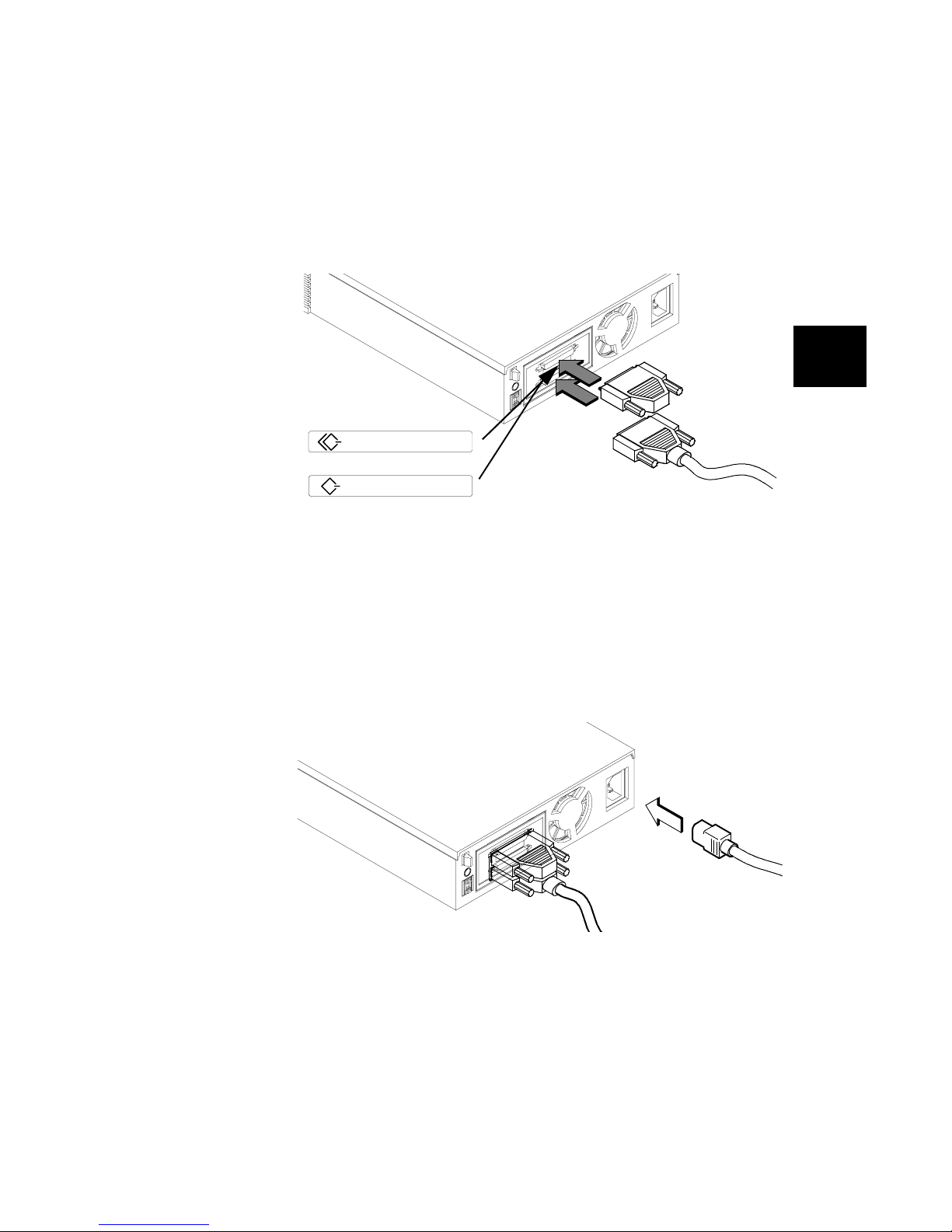
SCSI Terminator
(SE or Differential)
SCSI Label
SCSI DIFF
FAST WIDE–DIFF SC S I
SCSI SE
or
WIDE–SE / NARROW–SE SCSI
SCSI Cable
Figure 2-7 Connecting the SCSI Cable
8. Connect the Power Cable
CAUTION To ensure optimal performance, use the 3-wire power cord supplied with this
unit.
Connect the power cable to the disk drive unit and an AC wall outlet. See
Figure 2-8.
ENGLISH
Figure 2-8 Connecting the Power Cable
Disk Installation 2-7
To AC
Outlet
Page 24

9. Power On the Unit
Push in the power switch on the front of the unit to ensure that your drive is
recognized by your system during boot-up.
10. Configuring the Drive
Reference your workstation owner’s guide for instructions about using the
HP-UX sam utility to configure your drive.
11. Rack Mounting
The Rack-Ready Drives can be mounted into a standard HP 19-inch rack by
using the optional HP C4317A (2 EIA units ) or the C4 318B ( 3 EIA units ) rack
mount kits. See Appendix B for more details.
2-8 Disk Installation
Page 25

Specifications
Physical Dimensions 62mm(H) x 215mm(W) x 273mm(D)
Weight 2.8kg (6.1 lbs)
Data Interfa ce Wide SCSI Single-Ended, Dual High-Density 68-pin
Boot Disk Exceptions
Rated A/C Input 100-240V 50/60Hz. Max 1.2A
A/C Current Draw Typical: 0.4 A - 0.2 A
Typical Heat Dissipation 22 W, 75 BTU/hr
Mechanism Disk
Capacity 4.2 GB
Interface Transfer Rate Up to 40 MB/s Synchronous
Int. Transfer Rate 120-190 Mbits/sec
Cache 512 KB
Average Access Time 7.4ms Read, 8.1ms Write
Spindle Speed 7200 RPM
MTBF (Mechanism) 1,000,000 hours*
Warranty 2 Years
A
ENGLISH
Table 1: C6388B Desktop and C6389A Rack-Ready
4GB Wide Single-Ended/Narrow Single-Ended Disk Drive
HP 9000 Workstations & Servers: Supported on HP-UX
9.XX – 10.01 as data disks only. For HP-UX 10.10 and
above as data or boot disk.
Note *Hewlett-Packard Company does not warrant that this predicted MTBF is
representative of any particular unit installed for customer use. Failure rates
are derived from a large database of test samples. The actual failure rate will
vary from unit to unit.
Specifications A-1
Page 26

Table 2: C6390A Desktop and C6391A Rack-Ready
4GB Fast Wide Differential Disk Drive
Physical Dimensions 62mm(H) x 215mm(W) x 273mm(D)
Weight 2.8kg (6.1 lbs)
Data Interfa ce Fast Wide SCSI-3 Differential, Dual High-Density 68-pin
Boot Disk Exceptions
A/C Input Characteristics 100-240V 50/60Hz. Max 1.2A
A/C Current Draw Typical: 0.4 A - 0.2 A
Typical Heat Dissipation 22 W, 75 BTU/hr
Mechanism Disk
Capacity 4.2 GB
Interface Transfer Rate Up to 20 MB/s Synchronous
Int. Transfer Rate 120-190 Mbits/sec
Cache 512 KB
Average Access Time 7.4ms Read, 8.1ms Write
Spindle Speed 7200 RPM
MTBF (Mechanism) 1,000,000 hours*
Warranty 2 Years
HP 9000 Workstations: Supported on HP-UX 9.XX as data
disks only. For HP-UX 10.XX and above as data or boot
disk.
Note *+HZOHWW3DFNDUG&RPSDQ\GRHVQRWZDUUDQWWKDWWKLVSUHGLFWHG
07%)LVUHSUHVHQWDWLYHRIDQ\SDUWLFXODUXQLWLQVWDOOHGIRU
FXVWRPHUXVH)DLOXUHUDWHVDUHGHULYHGIURPDODUJHGDWDEDVHRI
WHVWVDPSOHV7KHDFWXDOIDLOXUHUDWHZLOOYDU\IURPXQLWWRXQLW
A-2 Specifications
Page 27

Table 3: C6394B Desktop and C6395A Rack-Ready
9GB Wide Single-Ended/Narrow Single-Ended Disk Drive
Physical Dimensions 62mm(H) x 215mm(W) x 273mm(D)
Weight 2.8kg (6.1 lbs)
Data Interfa ce Wide SCSI Single-Ended, Dual High-Density 68-pin
Boot Disk Exceptions
A/C Input Characteristics 100-240V 50/60Hz. Max 1.2A
A/C Current Draw Typical: 0.4 A - 0.2 A
Typical Heat Dissipation 22 W, 75 BTU/hr
Mechanism Disk
Capacity 9.1 GB
Interface Transfer Rate Up to 40 MB/s Synchronous
Int. Transfer Rate 120-190 Mbits/sec
Cache 512 KB
Average Access Time 7.4ms Read, 8.1ms Write
Spindle Speed 7200 RPM
MTBF (Mechanism) 1,000,000 hours*
Warranty 2 Years
HP 9000 Workstations & Servers: Supported on HP-UX
9.XX – 10.01 as data disks only. For HP-UX 10.10 and
above as data or boot disk.
Note *Hewlett-Packard Company does not warrant that this predicted MTBF is
representative of any particular unit installed for customer use. Failure rates
are derived from a large database of test samples. The actual failure rate will
vary from unit to unit.
ENGLISH
Specifications A-3
Page 28

Table 4: C6396A Desktop and C6397A Rack-Ready
9GB Fast Wide Differential Disk Drive
Physical Dimensions 62mm(H) x 215mm(W) x 273mm(D)
Weight 2.8kg (6.1 lbs)
Data Interfa ce Fast Wide SCSI Differential, Dual High-Density 68-pin
Boot Disk Exceptions Boot capable on all supported operating systems.
A/C Input Characteristics 100-240V 50/60Hz. Max 1.2A
A/C Current Draw Typical: 0.4 A - 0.2 A
Typical Heat Dissipation 22 W, 75 BTU/hr
Mechanism Disk
Capacity 9.1 GB
Interface Transfer Rate Up to 40 MB/s Synchronous
Int. Transfer Rate 120-190 Mbits/sec
Cache 512 KB
Average Access Time 7.4ms Read, 8.1ms Write
Spindle Speed 7200 RPM
MTBF (Mechanism) 1,000,000 hours*
Warranty 2 Years
Note *Hewlett-Packard Company does not warrant that this predicted MTBF is
representative of any particular unit installed for customer use. Failure rates
are derived from a large database of test samples. The actual failure rate will
vary from unit to unit.
A-4 Specifications
Page 29

Rack-Ready Modules
The 3U 4-Bay Rack Kit is designed for mounting into 1.1-meter, 1.6-meter,
and 2.0-meter HP 19-inch racks.
1. The HP C4317A (2 EIA units) and C4318B (3 EIA units) are designed
for horizontal mounting of four half-height products.
2. These rack enclosures include blind-mate, easy plug connectors providin g
easy installation and removal of Rack-Ready Modules. See Figure B-1.
3. The HP C4317A (not shown) and HP C4318B rack kits feature Wide 68-
pin SCSI connectors. Th is standardizes SC SI daisy-chaining inside the 19inch rack. Select the appropriate 50-pin to 68-pin or 68- pin to 68-pin cable
to connect the rack to your system.
B
ENGLISH
Figure B-1 C4318B 3U 4-Bay Rack Enclosure
Rack-Ready Modules B-1
Page 30

Installation and Removal of Drives
Lever in the Closed Position Lever in the Open Position
Figure B-2 Ejection Lever Assembly
The Rack-Ready Drives are equipped with an ejection lever assembly in place
of the rubber feet used on the desktop version. See Figure B-2. The ejection
lever assembly is designed for easy installation and removal of drives from the
rack mount kit.
1. Power down the host system.
2. Open the ejection lever assembly.
3. Installation: Slide the driv e into the enclosure until the drive’s po wer and
I/O port plug into the back of the rack mount kit.
4. Close the Ejection Lever assembly, locking the unit in place.
5. Removal: Move the ejection lever forward until the drive is disengaged
Note For comprehensive installation instructions see HP 3U 4-Bay Rack E nclosure
Installation Guide (HP part number C4318-90001) or HP 2U 2-Bay Rack
Enclosure Installation Guide (HP part number C4317-90002).
B-2 Rack-Ready Modules
from the rear power and I/O plugs. Slide the drive out of the enclosure, using
both hands to grasp the unit.
Page 31

Cable Accessories
C
ENGLISH
Cables and Te rminators
Connection
on System
FWD 68p FWD 68–68 0.9 C2911A
FWD 68p FWD 68–68 2.5 C2924A
FWD 68p WD WD terminator - C2905A
WSE 68p WSE 68–68 0.5m C2978A
WSE 68p WSE 68–68 1.5m C2979A
WSE 68p WSE SE terminator - C2972A
Device to
Device in Rack
NSE 50p WSE 50-68 1.0m C2961A
NSE 50p WSE 50-68 1.5m C2962A
NSE 50p WSE 50-68 2.0m C2906A
*All HP rack-ready devices connect to the rack enclosure through a blindmate, easy-plug connector. The connectors on the back of the rack enclosure
are all 68-pin. To connect a device in your rack enclosure with the host
system, you may need either a 5 0-pin or 68-pin cabl e depending on the type o f
bus used by the host system. (Wide single-ended cables can be used with
narrow single-ended devices.) For device-to-device connection in the rack u se
a C2981A (68p–68p) 0.5 meter cable.
Device
Type*
any 68–68 0.5m C2981A
Cable Pins
Cable
Length
Part
Number
WSE = wide single-ended NSE = narrow single-ended
FWD = fast wide differential p = pin
Cable Accessories C-1
Page 32

If your drive is the only SCSI device or if it is the last SCSI device in a daisychain of devices, you must install a terminator.
C-2 Cable Accessories
Page 33

Page 34

Copyright © 1998
Hewlett-Packard Company
Printed in USA 07/98
Manual Part No.
C6388-90001
* C6388-90001 *
 Loading...