

Page 1

HP
English: C5644-90943
SureStore
T4
Models T4i, T4e
User’s Guide
(Replace with Colour Cover Artwork)
Front Cover
Page 2

Product Details
Note your tape drive details here so you can find them easily when you need them.
Model name:
Product number:
Serial number:
Date purchased/installed:
SCSI ID:
HP SureStore T4_
Inside Front Cove r
Page 3

HP SureStore T4
User’s Guide
Page 4

© Copyright 1998 by Hewlett-Packard Company.
The information contained in this document is
subject to change w it hout notice.
This document contains proprietary information
which is protected by copyright. All rights are
reserved. No part of this document may be photocopied, repro duced or tran slated to anot her lang uage
without the prior written consent of Hewlett-Pa ckard
Company.
Hewlett-Packard shall not be liable for errors
contained herein or for incidental or consequential
damages (inclu ding lost profits) in connection with
the furnishing, performance, or use of this material
whether based on warranty, contract, or other legal
theory.
March 1998
Part Number C5644-90943
Page 5

Contents
1 Preparing for Installation
Your New HP SureStore T4 Tape Drive 1-2
Before You Start 1-2
Internal Drives 1-3
Check the Contents of the Box 1-3
Installation Overview 1-4
External Drives 1-5
Check the Contents of the Box 1-5
Installation Overview 1-6
Checking System Prerequisites 1-7
Hardware Requirements 1-7
Operating System Requirements 1-8
Backup Software 1-8
Planning the SCSI Bus 1-9
Checking Your Cur r ent SCSI Con figuration 1-9
What Next? 1-10
2 Installing an Internal Tape Drive
Overview of the Installation Process 2-2
Tools You May Need 2-3
Preparing the Computer 2-3
Preparing the Tape Drive 2-5
Installing the Tape Drive in the Bay 2-8
Verifying the Installation 2-11
What Next? 2-12
3 Installing an External Tape Drive
Overview of the Installation Process 3-2
Tools You May Need 3-2
Preparing the Tape Drive 3-3
Installing the Tape Drive 3-5
Verifying the Installation 3-8
What Next? 3-8
1
Page 6

Contents
4 Caring for Your Tape Drive
Care of the Tape Drive 4-2
Choosing Tapes for Your Tape Drive 4-3
Erasing Tapes 4-3
Inserting and Removing Tape Cartridges 4-4
Write-Protecting a Tape Cartridge 4-6
Caring for Your Tape Cartridges 4-7
Operating Conditions 4-7
Storing Tape Cartridges 4-7
5 Troubleshooting
Save Yourself a Call 5-2
Troubleshooting Tips 5-2
Things to Try First 5-3
TapeAssure 5-3
Problems with Your Co m puter 5-3
Problems with Your Tape Drive 5-4
Contents-2
6 Product Specifications and Ordering Information
Interface A-2
Backup Speed A-2
Tape Format A-2
Reliability Specifications A-3
Power Requirements A-3
Physical Specifications A-3
Certifications A-3
Ordering Information A-4
Tape Cartridges A-4
SCSI Accessories A-4
7 Customer Support
Warranty B-2
Service and Support B-3
Contacting Customer Support B-6
Page 7

1
Preparing for Installation
This chapter provides an overview of the installation process and tells you what you
will need before installing the HP SureStore T4 tape drive.
Page 8

Preparing for Installation
Your New HP SureStore T4 Tape Drive
Your New HP SureStore T4 Tape Drive
The HP SureStore T4 tape drive p rovides reliable data protection at an af fordable price.
The HP SureStore T4 integrates easily into your small network server, peer-to-peer
network, or desktop compute r. Based on T rav an (TR-4) technology , each tape cartridge
has a native storage capacity of 4 GB, enough capacity to back up a small server or
peer-to-peer network on a single tape. If your backup application provides software
data compression, a single tape may store up to 8 GB of data (assuming a 2:1
compression ratio).
Before You Start
Before you install your HP SureStore T4 drive:
Check the contents of the box against the list on page 1-3 for internal drives or page
1
page 1-5 for external drives.
Write your drive’s serial number and other details on the inside front cover of this
2
book. The serial number can be found inside the drive’s tape door. The product
number is:
1-2
T4i internal drive: C5644C
•
T4e external drive: C5645B
•
Check that your computer meets the requirements for installation.
3
Collect information about the SCSI configuration of your computer and any other
4
devices attached to it and decide how you are going to configure the drive on the
SCSI bus. You can use the TapeAssure software provided on the
CD-ROM to do this.
Tape
Select a free bay for an internal drive.
5
or
Select a site for an external drive.
HP SureStore
Page 9
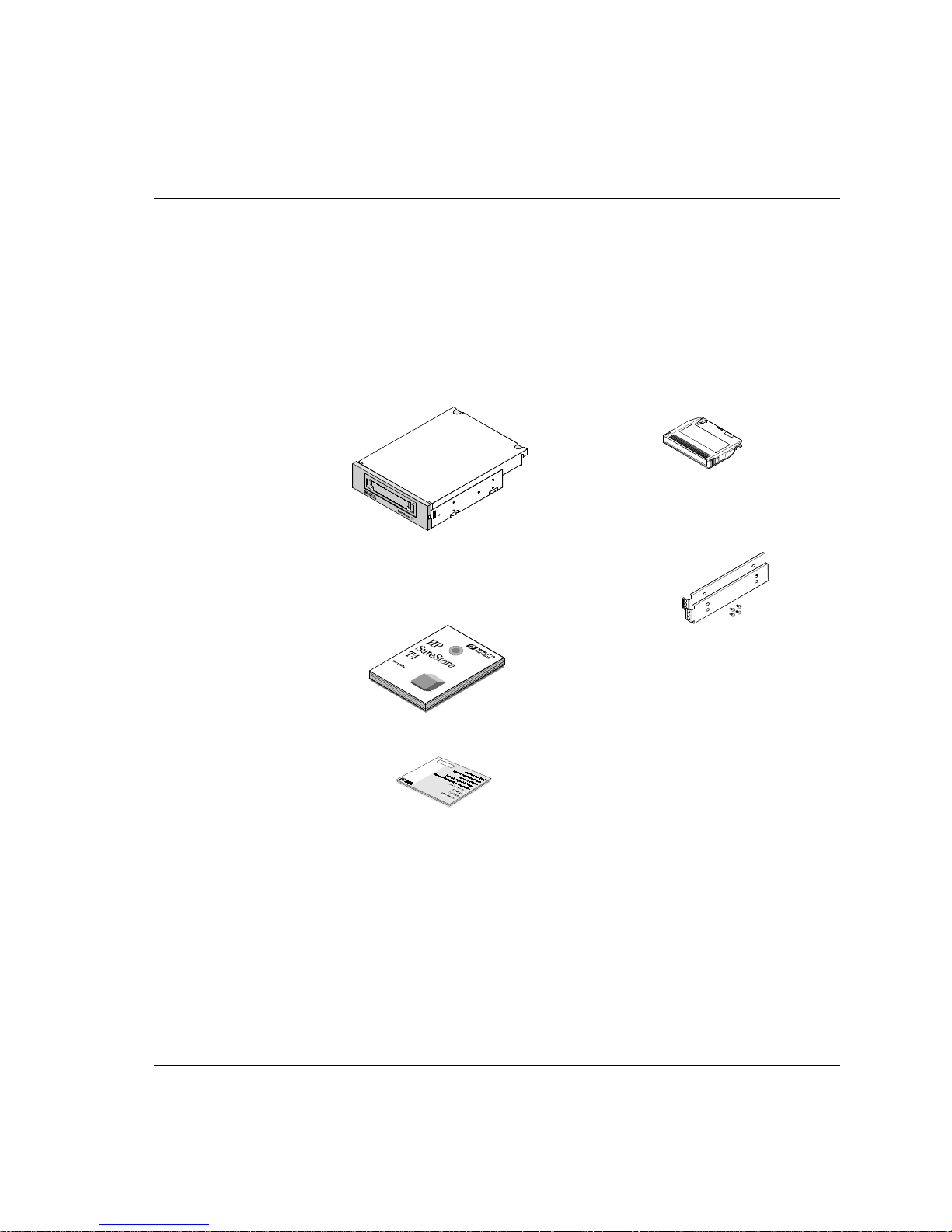
Internal Drives
Check the Contents of the Box
Check each item that came in the HP SureStore T4 box to make sure you have
everything you need. Take a moment now to write the model name (T4i), product
number (C5644C), and ser ial nu mber (l ook i nside the ta pe do or) of yo ur ta pe drive on
the inside front cover of the
Preparing for Installation
User’s Guide
.
HP SureStore T4i tape drive HP TR-4 mini-cartridge
Rails and screws suitable for mounting
the tape drive in an HP NetServer E
E-series or Vectra computer
User’s Guide
(Please discard the unneeded
languages in the recycling bin.)
Internal Drives
HP SureStore Tape
containing:
•
Colorado Backup
•
Stac Replica Backup for NetW are,
Customer Care Card and label
If anything is missing or appears damaged, contact your deliv ery company or supplier .
HP SureStore Tape Edition
•
Stac Replica Backup for NT, HP
SureStore Tape Edition
•
TapeAssure
•
Driver software
CD-ROM
1-3
Page 10

Preparing for Installation
Internal Drives
Installation Overview
Installing the HP SureSto r e T4 tape drive is a simple procedure requiring no special
skills, providing that your system meets the prerequisites and you have the right tools.
The hardware installation process should take less than an hou r.
See “Checking System Prerequisites” on page 1-7.
Check System
Prerequisites
Prepare
Computer
Properly installed and configured SCSI controller
•
CD-ROM drive to load software
•
Empty 5¼-in b ay
•
Mounting hardware, if required for your computer
•
SCSI cable with available 50-pin connector
•
See “Preparing the Computer” on page 2-3.
Perform a normal system shutdown
•
Remove power cables
•
Remove cover
•
Remove cover plate and any mounting hardware from
•
bay
Prepare
Tape Drive
Install
Tape Drive
Test
Tape Drive
Install Driver
Software
See “Preparing the Tape Drive” on page 2-5.
Check SCSI ID and reset if necessary
•
Check termination and change if necessary
•
Attach rails or other mounting hardw are if requir ed for
•
your computer
See “Installing the Tape Drive in the Bay” on page 2-8.
Slide drive into bay
•
Attach SCSI cable
•
Attach power cable
•
Secure drive in place with screws
•
Replace computer’s cover
•
Reconnect power cables
•
See “Verifying the Installation” on page 2-11.
Switch on computer and boot up
•
Install TapeAssure from CD-ROM
•
Run TapeAssure and perform a test backup and restore
•
See “What Next?” on page 2-12.
Ensure that the appropriate drivers are installed
•
1-4
Page 11
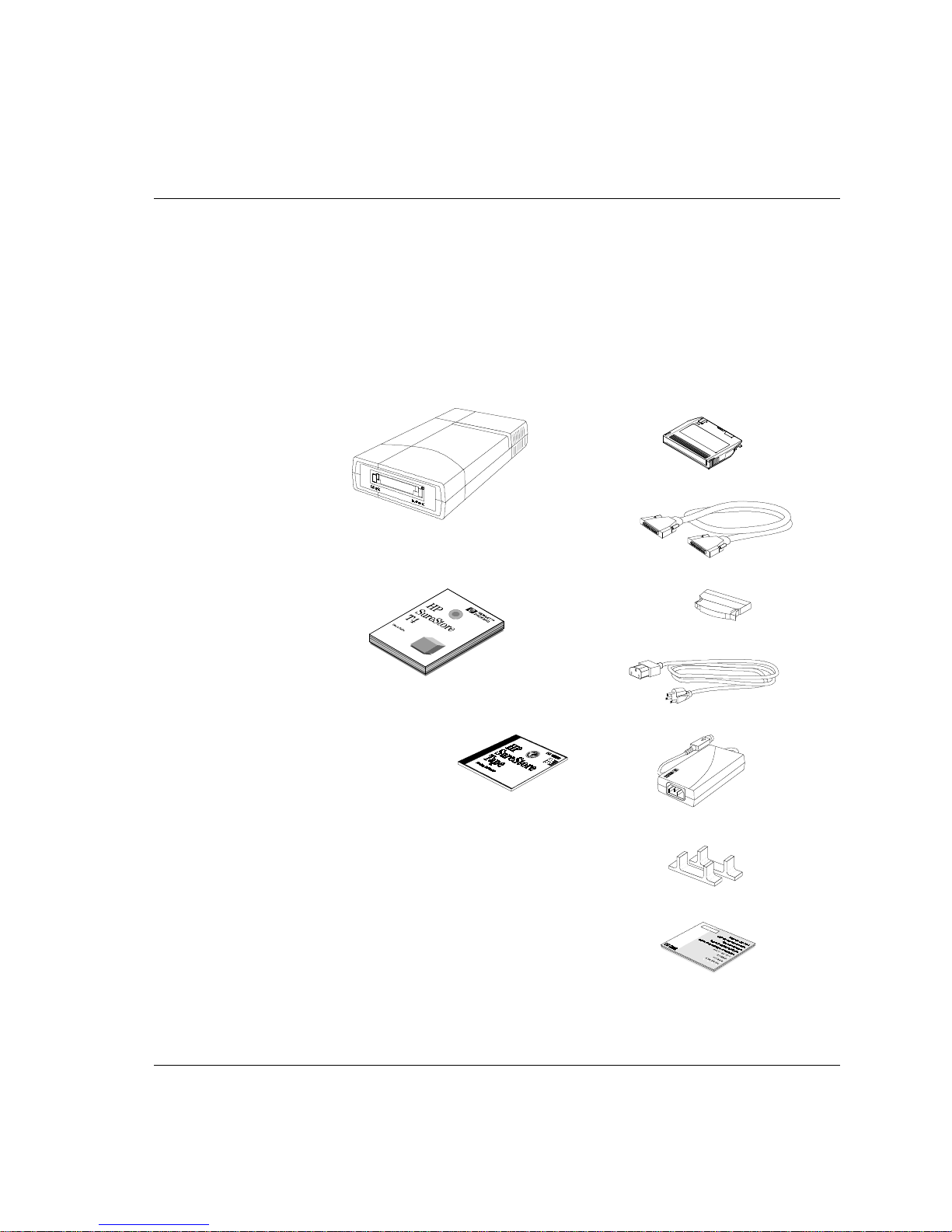
External Drives
Check the Contents of the Box
Check each item that came in the HP SureStore T4 box to make sure you have
everything you need. Take a moment now to write the model name (T4e), product
number (C5645B), and ser ial nu mber (l ook i nside the ta pe do or) of yo ur ta pe drive on
the inside front cover of the
HP SureStore T4e tape drive HP TR-4 mini-cartridge
User’s Guide
User’s Guide
(Please discard the unneeded
languages in the recycling bin.)
Preparing for Installation
External Drives
.
SCSI cable
SCSI terminator
Power cable
HP SureStore Tape
containing:
•
Colorado Backup
•
Stac Replica
Backup for
NetWare, HP
SureStore Tape Edition
•
Stac Replica Backup for NT, HP
SureStore Tape Edition
•
TapeAssure
•
Driver software
CD-ROM
Power supply
Stands for vertical mounting
Customer Care Card and label
If anything is missing or appears damaged, contact your deliv ery company or supplier .
1-5
Page 12
Preparing for Installation
External Drives
Installation Overview
Installing the HP SureSto r e T4 tape drive is a simple procedure requiring no special
skills, providing that your system meets the prerequisites. The hard ware installation
process should take about 15 minutes.
See “Checking System Prerequisites” on page 1-7.
Check System
Prerequisites
Prepare
Tape Drive
Install
Tape Drive
Properly installed and configured SCSI controller
•
CD-ROM drive to load software
•
High-density, 50-pin SCSI connector
•
See “Preparing the Tape Drive” on page 3-3.
Check SCSI ID and reset if necessary
•
Check termination and attach terminator if necessary
•
Attach stands, if desired
•
See “Installing the Tape Drive” on page 3-5.
Perform a normal system shutdown
•
Remove power cables
•
Attach SCSI cable
•
Attach power supply to tape drive
•
Attach power cord to po wer sup ply an d p lug in to ou tlet
•
Reconnect computer’s power cables
•
1-6
Test
Tape Drive
Install Driver
Software
See “Verifying the Installation” on page 3-8.
Switch on computer and boot up
•
Install TapeAssure from CD-ROM
•
Run TapeAssure and perform a test backup and restore
•
See “What Next?” on page 3-8.
Ensure that the appropriate drivers are installed
•
Page 13

Checking System Prerequisites
Before you instal l your HP SureStore T4 tape drive o n y our computer , m a k e s ure t hat
you have all the necessary hardware and information you will need.
Hardware Requirements
To install the HP SureStore T4 tape drive, your computer must be a 386-, 486-, or
Pentium-based computer that has:
A properly installed SCSI host adapter (or a SCSI controller on the motherboard)
with the appropriate Advanced SCSI Programming Interface (ASPI) driver
A CD-ROM drive to install the software
Preparing for Installation
Checking System Prerequisites
For an
internal
An available 5¼-inch, half-height drive bay
Any special tray or rails required to fix the drive into the empty bay (Rails are
provided for the HP NetS erver E-series servers or Vectra computers.)
A SCSI ribbon cable with an available 50-pin connector. Your computer may
already have this cable. If not, contact your dealer.
For an
external
You may have to open up your computer to determine whether it has the necessary
components and to check the SCSI ID settings. See “Preparing the Computer” on
page 2-3 for instructions on how to do this.
While installation is similar for all computers, there are variations among them. You
may want to h av e your comput er manuals a v ailable to hel p you remo ve the computer’ s
cover and identify internal components.
drive, you will also need:
drive, your computer must have a 50-pin high-density connector.
1-7
Page 14

Preparing for Installation
Checking System Prerequisites
Operating System Requirements
The HP SureStore T4 tape drive is compatible with the following operating systems:
Novell NetWare (v3.12 and 4.11)
Microsoft Windows NT (v3.51 and 4.0)
Microsoft Windows 95
Microsoft Windows (v3.1 and 3.11)
DOS 5.0 or higher
SCO UNIX Open Desktop 3 (3.2v4.2) and OpenServer 5 (3.2v5.02)
You can also use your HP SureStore T4 with many other operating sy st ems , but thirdparty backup software may be required.
Backup Software
To test and use your HP SureStore T4 tape drive, you will need backup software that
supports the drive. The tape drive comes with software drivers to support the backup
utilities for three common network operating systems:
Microsoft Windows NT Backup utility (no data compression available)
SCO UNIX utilities, such as
Check the README file on the
information about the software drivers supplied with the tape drive.
and
tar
cpio
HP SureStore Tape
(no data compression available)
CD-ROM for the latest
1-8
For standalone or peer-to-peer systems, the following backup applications and
associated documentation are provided on the
Colorado Backup for Windows (provides data compression)
Colorado Backup for Windows 95 (provides data compression)
Colorado Backup for DOS (provides data compression)
HP SureStore Tape
CD-ROM:
For server systems, the following backup applications and associated documentation
are provided on the
Stac Replica Backup for NetWare, HP SureStore Tape Edition
Stac Replica Backup for NT, HP SureStore Tape Edition
HP SureStore Tape
CD-ROM:
Other commercial backup applications are also available. For the latest list of backup
packages and drivers that support this tape drive, refer to our World Wide Web site
(
http://www.hp.com/go/tape
).
Page 15

Planning the SCSI Bus
The SCSI controller in your computer links the computer to your tape drive and
possibly other devices through the SCSI bus. If you have other SCSI devices in
addition to the tape drive, you need to decide where the tape drive will go in relation
to the other devices. If the tape dri ve is going to be the only device on the b us, there is
no decision to make: you can use the drive’s defaults.
Each device on a SCSI bus, including the SCSI controller itself, must have a unique
address, a number from 0 to 7, called the
for the SCSI controller because it has the highest priority on the bus. A SCSI boot disk
usually has a SCSI ID of 0. The tape drive should be assigned an unused SCSI ID
between 1 and 6. The tape drive’s default is 4. To configure the drive properly when
you install it, you will need to identify the SCSI IDs of any other devices on the SCSI
bus to be sure that there is no conflict with the tape drive’s SCSI ID.
SCSI buses must be terminated correctly at each physical end of the cable. An internal
HP SureStore T4 tape drive comes with a set of resistors that can be removed if th e tape
drive is not at the end of the SCSI chain. An external T4 driv e comes with a terminator
block that fits on one of the drive’s SCSI connectors.
SCSI ID
or
target ID
Preparing for Installation
Planning the SCSI Bus
. SCSI ID 7 is reserved
Both internal and external drives use
on the same bus with
active termination, the tape drive must not be placed at the end of the SCSI bus. Instead,
remove the drive’s termination and place the drive between the SCSI card and the last
device on the bus. If this is not possible, purchase an activ e terminator for the tape drive
or install a second SCSI host adapter to support the tape drive.
If you need more i nformation about ar ranging you r SCSI bus , refer to our World Wide
Web site (
the telephone numbers listed in Appendix B).
http://www.hp.com/go/tape
active termination
passive termination
. If a SCSI bus has devices or cables that use
Checking Your Current SCSI Configuration
The T apeAssure softw are provided on the
check your computer’s current SCSI configuration. If you are not sure what this
configuration is, install and run TapeAssure from the CD-ROM. This will check for the
presence of a SCSI controller and its driver software and identify the SCSI IDs of
existing SCSI devices. Exit the program after you view the SCSI configuration
information.
HP SureStore T ape
, which should not be mixed
) or the HP First faxback system (see
CD-ROM can be used to
1-9
Page 16

Preparing for Installation
What Next?
What Next?
If your computer has all the hardware and software it needs to support the tape drive,
you are ready to start installing the drive.
If your drive is internal, go to Chapter 2.
If your drive is external, go to Chapter 3.
1-10
Page 17

2
Installing an Internal Tape Drive
This chapter provides directions for installing an HP SureStore T4i drive in your
computer.
The entire hardware installation process should take about an hour.
Page 18
Installing an Internal Tape Drive
Overview of the Installation Process
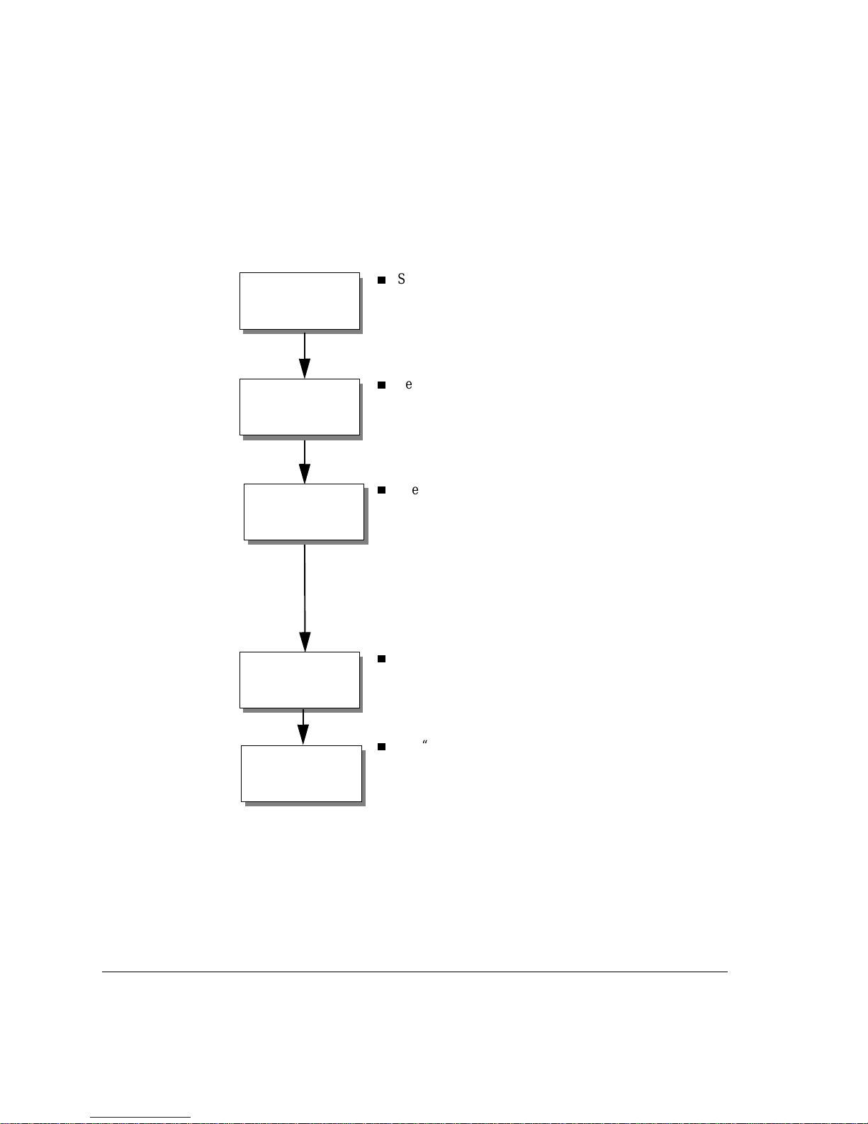
Overview of the Installation Process
There are four major steps in the installation process:
Preparing the computer by shutting down all applications, turning off the power,
1
removing the cover, and checking for cables and mounting hardware.
Preparing the tape drive by checking the SCSI ID (and changing it if necessary) and
2
attaching any mounting hardware (tray or rails) that may be needed.
Installing the tape drive in the empty bay and connecting the SCSI and power
3
cables.
Verifying that the tape drive is properly installed and functional by running
4
TapeAssure.
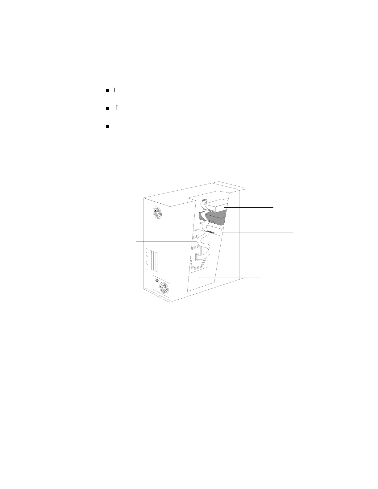
Figure 2.1 Installing an internal tape drive in your computer
2-2
Page 19

Tools You May Need
You may need th e following tools to complete the installation:
A medium-size Phillips screwdriver
A medium-size flat-bladed screwdriver (if your computer uses slotted screws)
A Torx screwdriver (if your computer uses Torx screws)
Needle-nose pliers
A grounding mat or wrist strap (optional but recommended)
Preparing the Computer
Before you begin the inst allati on process , ensure th at your comp uter is equip ped with
a SCSI host adapter or on-board SCSI controller with its associated driver installed
according to the directions in its installation guide.
You may want to have your computer manuals available for reference during this
procedure.
Installing an Internal Tape Drive
Tools You May Need
Caution
Caution
Static electricity can damage electronic components. Turn all equipment off before
removing the computer’s cover. A grounding mat or wrist strap provides the be st
protection against static. If you don’t have either of these, always touch the
computer’s chassis before touching any internal boards or devices.
If there are other SCSI devices in your computer, you may want to check their SCSI
1
ID numbers and termination status before you switch off the computer. See “Planning
the SCSI Bus” on page 1-9 for more information.
Close down all applications, switch of f th e comp uter and an y perip herals, and unp lug
2
them from the power outlets.
Remove the cover from your computer.
3
As you work inside your computer, you may find that you have to disconnect the
internal SCSI cable or power cable fr om other de vices to maneuv er the ne w tap e dri v e
into place. If you do this, take note of existing cable connections and their orientation,
so you can put them back correctly later.
2-3
Page 20
Installing an Internal Tape Drive
Preparing the Computer
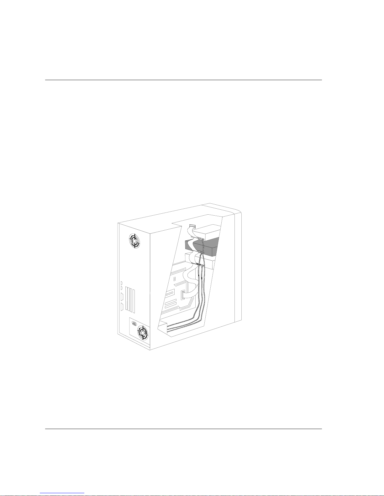
Determine whether you need another SCSI cable.
4
If your SCSI controller has a ribbon cable attached to it and there is an unused
connector, you will not need another SCSI cable. Go to step 5.
If your SCSI controller does not have a cable attached to it, you will need a new
SCSI cable. Once you have this cable, go to step 5.
If your SCSI host adapter has a cable attached to it but there are no available
connectors, you must do one of the following:
Install a SCSI cable with more connectors (a SCSI host adapter can support up
•
to seven devices)
Install another SCSI host adapter and cable
•
Figure 2.2 SCSI cable connections
Terminator block
Other internal
SCSI devices
Tape
drive
SCSI cable
Connection to
SCSI controller
Locate an available 5¼-inch, half-height drive bay in your computer.
5
Remove the cover plate and any mounting hardware (screws, rails, or a tray, for
6
example) from the bay. Keep any mounting hardware that can be used to secure the
tape drive in the bay.
If your computer requires special mounting hardware that you do not have, you must
purchase this hardware before continu i ng.
Make sure the available SCSI connector reaches the back of the empty bay in which
7
you plan to install the new tape drive, as shown in figure 2.2.
Locate an available internal po wer cable and make sure it reaches the back of the em pty
8
bay.
2-4
Page 21
Preparing the Tape Drive
To prepare the tape drive for installation, you need to make sure that it has the correct
SCSI ID and termination settings. Each SCSI device requires a unique SCSI ID. You
need to change the tape drive’s default SCSI ID setting of 4 only if the computer
already has a device with ID 4. See “Planning the SCSI Bus” on page 1-9 for more
information about SCSI IDs and SCSI bus termination.
Check the tape drive’s SCSI ID setting to ensure that it is set to the number you expect.
1
If you do not need to change the SCSI ID
inside front cover of this book and then go to step 4.
Installing an Internal Tape Drive
Preparing the Tape Drive
, note the default SCSI ID of 4 on the
To change the tape drive’s SCSI ID
Caution
Static electricity can damage electronic components. To equalize the static electricity
between the tape drive and the comp uter , rest the tape drive in its plastic bag on top of
the computer’s chassis while you remove the drive from the bag. Handle the drive as
little as possible during the installatio n procedure.
Locate the jumper block on the edge of th e circuit board that runs along the back of the
2
tape drive. (See figure 2.4.) Set the SCSI ID by moving the jumpers to the correct
position. (See figure 2.3.) Use needle-nose pliers or your fingers to move the jumpers.
Make a note of the SCSI ID setting on the inside front cover of this book for future
reference.
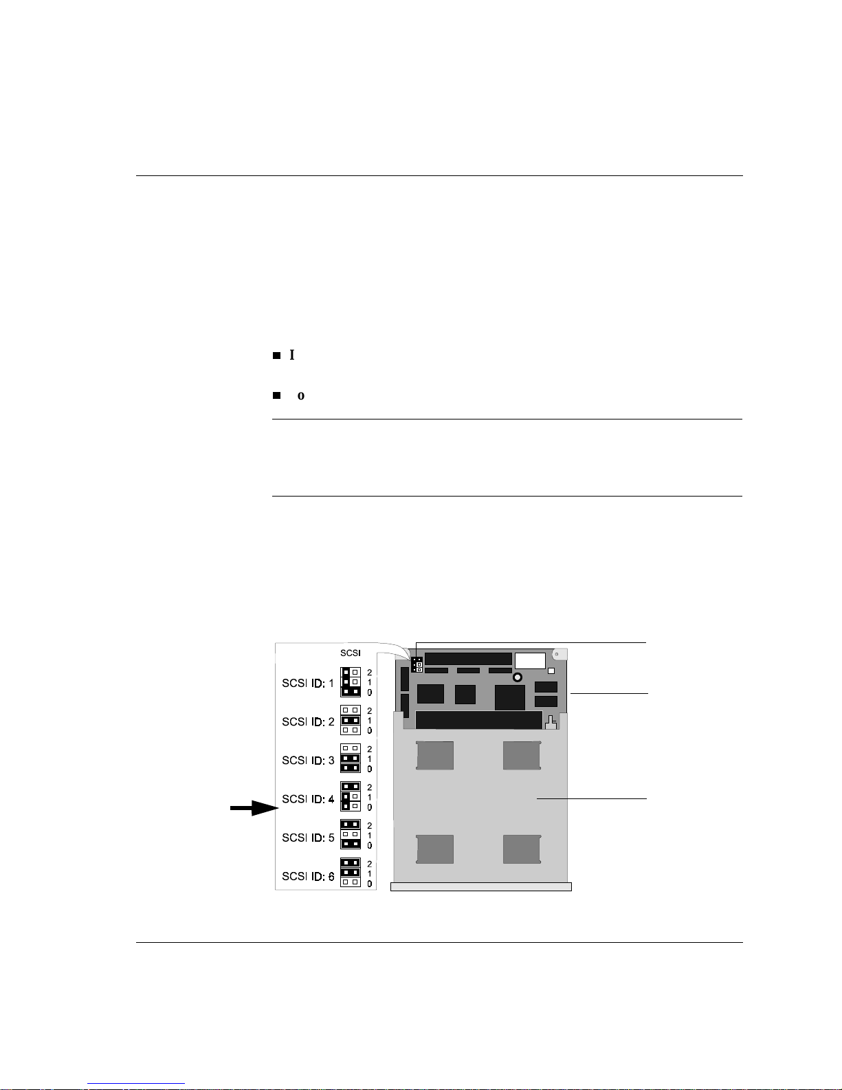
Figure 2.3 SCSI ID jumper settings
Default
Setting
, continue with the next step.
Jumpers
Circuit board
on back edge
of drive
Bottom of
tape drive
2-5
Page 22
Installing an Internal Tape Drive
s
Preparing the Tape Drive
Determine whether the tape drive should be terminated or unterminated.
3
If the tape drive is the last device or the only dev ice on the internal SCSI bus and
•
the computer’s SCSI ribbon cable has no active termination, the tape drive’s
terminating resistors should remain in place. Any other device between the SCSI
controller and the tape drive must not be terminated. Go to step 4.
If the tape drive is not the last device on the internal SCSI bus and/or the
•
computer’s SCSI ribbon cable has active termination (a terminator block on the
end of the cable or an in-line terminator), you must remove the terminating
resistors from the bottom of the tape drive, as shown in figure 2.4.
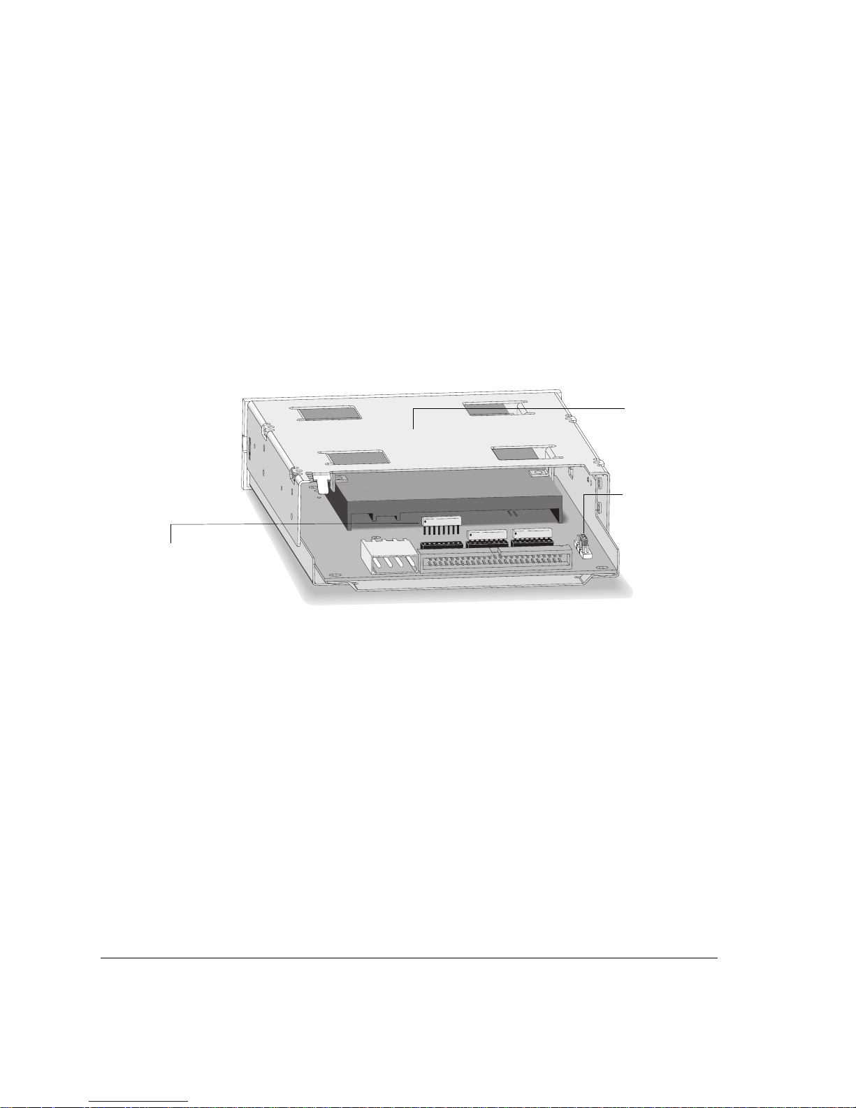
Figure 2.4 Removing the terminating resistors
Bottom of
tape drive
SCSI ID jumper
Lift the three resistors
straight out of their
sockets usin g
needle-nose pliers
2-6
Page 23
If your computer requires special rails or other hardware to install the tape drive, mount
4
them on the tape drive in this step. Many computers require no special mounting
hardware, however. If other devices in your computer are not mounted with special
rails or tray, proceed with the next section, “Installing the Tape Drive in the Bay” on
page 2-8.
If you are installing the drive in an HP NetServer E-series or an HP Vectra, attach
the HP rails to tape drive with the screws provided, as shown in figure 2 .5.
If your computer uses mounting hardware (either rails or a tray) and you have a
spare set, attach them to the tape dri ve as directed in your computer docu mentation.
If you do not have the appropriate mounting hardware for your computer, contact
your computer dealer or manufacturer to p urchase it. Attach the mounting hardware
to the tape drive, then proceed with the next section, “Installing the Tape Drive in
the Bay” on page 2-8.
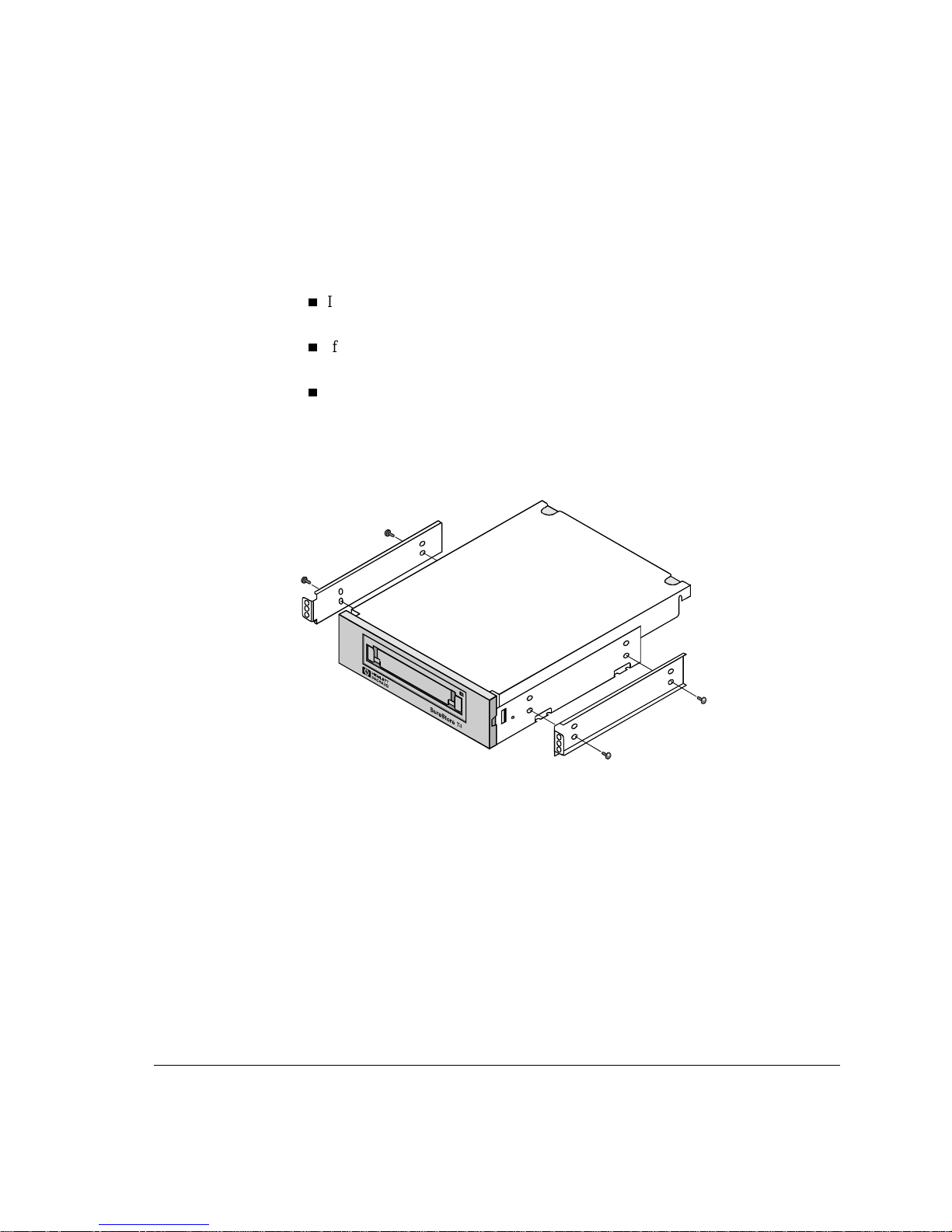
Figure 2.5 Attaching rails for an HP NetServer E-Series or Vectra computer
Installing an Internal Tape Drive
Preparing the Tape Drive
Screws go into
bottom set of holes
on both rails and
tape drive
2-7
Page 24
Installing an Internal Tape Drive
Installing the Tape Drive in the Bay
Installing the Tape Drive in the Bay
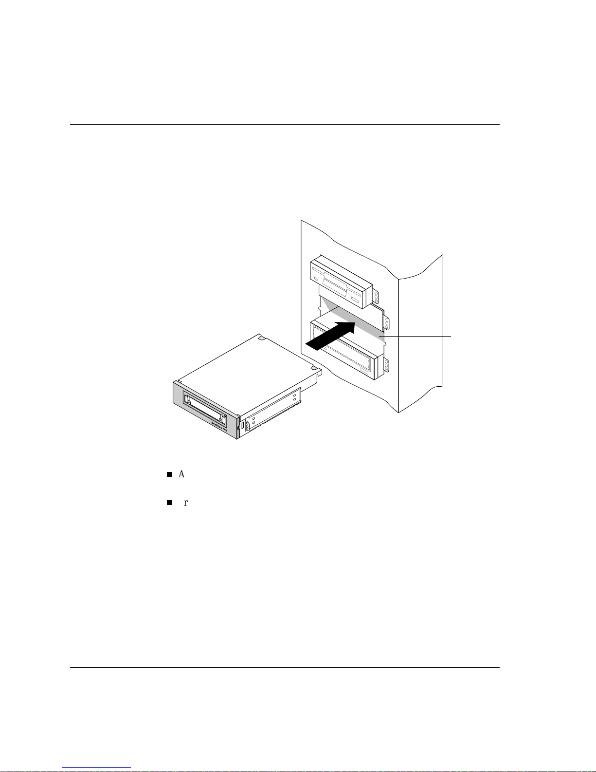
Slide the tape drive into the open bay. (See figure 2.6.) If your computer uses rails,
1
align them with the slots or fittings in the bay. Do not secure the drive with screws at
this point because you may have to move the drive a bit to get the cables into place.
Figure 2.6 Fitting the tape drive into an empty bay
Your drive may or may
not use rails to slide in to
the empty bay.
Half-height
drive bay
2-8
Attach the SCSI cable to the tape drive, as shown in figure 2.7 and figure 2.8.
2
Align the raised square on the cable’s connector with the slot on the tape drive’s
connector.
Press the connectors gently but firmly together.
Page 25

Figure 2.7 SCSI cable connections
Terminator block
SCSI cable
Plug one of the computer’s power cables into the back of the tape drive. (See
3
figure 2.8.)
Installing an Internal Tape Drive
Installing the Tape Drive in the Bay
Other internal
SCSI devices
Tape
drive
Connection to
SCSI controller
Align the beveled edges o f the computer’s power connector with the be v eled edges
of the drive’s connector.
Insert it into the drive’s power connector and press the connectors firmly together.
Figure 2.8 Connecting the power cable and SCSI cable
Align the plastic square
on the cable’s connector
with the slot on the
drive’s connector.
SCSI cable
Power cable
2-9
Page 26

Installing an Internal Tape Drive
Installing the Tape Drive in the Bay
Secure the tape drive in the bay.
4
Position the drive so its face plate is aligned with the front of the computer. Other
installed devices should give you an idea of positioning.
Align the screw holes in the drive’s mounting hardware with the holes in the drive
bay. Depending on your computer, the screws may go in on the front of the bay or
through the sides of the chassis. (See figure 2.9 or figure 2.10.)
Fix the drive into place with screws.
Use the screws that held on the cover plate if your computer has mounting
•
hardware that fixes the tape drive in from the front (figure 2.9).
Use the screws provided with the HP rails if you are fixing the tape drive in
•
through the sides of the chassis.
Figure 2.9 Fixing the tape drive in a system with mounting hardware
2-10
Page 27

Figure 2.10 Fixing the tape drive in a chassis-mount system
Reconnect any internal cables you may have removed from other devices and check
5
that no cables or boards were knocked loose during installation.
Installing an Internal Tape Drive
Verifying the Installation
If your computer’s cover uses blank plates over empty bays, remove the plate that
6
corresponds to the new tape drive’s position.
Replace the computer’s co ver.
7
Reconnect any external cables and power cords you removed.
8
Plug in the computer and peripherals.
9
Verifying the Installation
Once you hav e installed the t ape driv e hardware, you s hould verify th at it is functioni ng
properly before you store your valuable data. The TapeAssure software on the
HP SureStore Tape CD-ROM will perform a series of tests on the tape drive to verify
that it has been properly installed and provide guidance on what to do if there is a
problem.
Switch on the computer and boot it up. If you encounter any prob lems, refer to Ch apter
1
5, “Troubleshooting.”
2-11
Page 28

Installing an Internal Tape Drive
What Next?
Install TapeAssure using the setup pr ogram on the HP SureStore Tape CD-ROM.
2
In Windows NT, you can install TapeAssure directly on the server. In NetWare, you
will need to install TapeAssure on the server from a client workstation running
Windo ws 95. TapeAssure can be installed directly on a standalone computer that runs
Wind ows 95.
Run TapeAssure and follow the on-screen instructions to verify that your new tape
3
drive is operational. No other backup program should be running at the same time.
Have a blank cartridge ready for the write-to-tape test, which you should perform to
check that the drive can back up data to tape. (For tape loading instructions, see
page 4-4.)
What Next?
When the tape dri v e has passed the test s run by TapeAssure, you can be conf iden t that
you have installed it correctly.
Before you can use the tape drive, your backup software or operating system may
require the appropriate driver software for the tape drive. Follow the instructions in
your software documentation to install the driver. Some operating systems come with
drivers that support the HP SureStore T4, while others require the drivers supplied on
the HP SureStore Tape CD-ROM. Refer to the README file on the CD for the latest
information on which drivers are supplied.
Chapter 4 provides details of how to operate and care for the dri ve. Make sure you read
the advice about choosing and caring for tape cartridges.
2-12
Page 29

3
Installing an External Tape Drive
This chapter provides directions for installing an HP SureStore T4e drive in your
computer.
The hardware installation process should take about 15 minutes.
Page 30

Installing an External Tape Drive
Overview of the Installation Process
Overview of the Installation Process
There are four major steps in the installation process:
Preparing the tape drive by checking the SCSI ID and termination requirements
1
(and changing them if necessary).
Preparing the computer by shutting down all applications an d turning off the power.
2
Connecting the SCSI cable.
3
Connecting the power cord.
4
Verifying that the tape drive is properly installed and functional by running
5
TapeAssure.
Figure 3.1 Installing an external tape drive in your computer
Tools You May Need
You do not need any special tools to install the drive. If you need to change the SCSI
ID on the drive, you will need a narrow pointed object such as a ball-point pen or a
small screwdriver.
3-2
Page 31

Preparing the Tape Drive
To prepare the tape drive for installation, you need to make sure that it has the correct
SCSI ID and termination settings. Each SCSI device requires a unique SCSI ID. You
need to change the tape drive’s default SCSI ID setting of 4 only if the computer
already has a device with ID 4. See “Planning the SCSI Bus” on page 1-9 for more
information about SCSI IDs and SCSI bus termination.
Check the tape drive’s SCSI ID setting to ensure that it is set to the number you expect.
1
If you do not need to change the SCSI ID
inside front cover of this book and then go to step 3.
Installing an External Tape Drive
Preparing the Tape Drive
, note the default SCSI ID of 4 on the
To change the tape drive’s SCSI ID
Locate the SCSI ID selector on the back panel of your tape drive (see figure 3.2) and
2
use a pen or small screwdr iv er to press the but tons on the top or bott om of the SCSI ID
selector until the correct SCSI ID number is displayed.
Figure 3.2 SCSI ID selector on rear panel of tape drive
Note
Both the computer and the tape drive check the SCSI ID only at power-on. If you
change the tape drive’s SCSI ID while the system is running, the new SCSI ID will
not take effect until next time the system and the tape drive are powered on.
, continue with the next step.
Press thes e – and +
buttons to change
the SCSI ID setting
3-3
Page 32

Installing an External Tape Drive
Preparing the Tape Drive
Determine whether the tape drive should be terminated or unterminated.
3
Is the tape drive the only device on the SCSI bus?
If yes, attach the tape drive’s terminator block to one of the SCSI connectors on
•
the back of the tape drive, as shown in figure 3.3.
Is there another external device on the SCSI bus?
If yes, attach the tape drive in the middle of the SCSI chain, allowing the other
•
external device to provide termination. Plug the tape drive into the computer’s
SCSI connector and plug the other device into the tape drive’s second SCSI
connector. The device that comes last in the chain must be actively terminated.
Do not use the T4e’s passive terminator for this purpose.
Is there an internal device on the SCSI bu s?
If yes, the internal de vice probably has activ e termi nation, which means th at you
•
cannot connect the T4e onto the same SCSI bus. You must either purchase an
active terminator for the T4e from your supplier or install a second SCSI host
adapter to support the tape drive.
Note Remember that if you have devices attached to your SCSI host adapter both inside
your computer and external to your computer, the SCSI host adapter must NOT be
terminated (since it is, therefore, in the middle of the SCSI chain). Consult your SCSI
host adapter documentation for instructions on how to change the board’s termination.
Figure 3.3 Attaching the terminator block
Terminator
block
3-4
The terminator block
can be attached to
either
connector.
Page 33

Installing the Tape Drive
Perform a normal system shutdown and turn off the computer and any connected
1
peripherals. Disconnect the power cable from the outlet.
(Optional.) To save space on your desk, attach the two plastic stands that came with
2
your tape drive to the edge of the tape drive that is adjacent to the drive’s power plug,
as shown in figure 3.4.
Figure 3.4 Attaching the stands
Installing an External Tape Drive
Installing the Tape Drive
Note
The drive can also be used without the plastic stands by laying it flat on its rubber
feet. The following illustrations show it without the plastic stands.
3-5
Page 34

Installing an External Tape Drive
Installing the Tape Drive
Attach one end of the SCSI cable to one of the connectors on the back of the tape driv e
3
(it does not matter which connector you use). Press the clips on the sides of the
connector as you attach it, then release the clips, making sur e that the cable is securely
attached.
Figure 3.5 Attaching the SCSI cable
SCSI cable
Tape drive
3-6
Attach the other end of the SCSI cable to your computer’s external SCSI connector.
4
Page 35

Connect the power supply to the power connector on the back of the tape drive, with
5
the arrow on the cable end facing up, as shown in figure 3.6.
Connect the power cord to the po wer supply and then to a wall outlet or po wer strip, as
6
shown in figure 3.6.
When you plug in the power supply and attach it to the tape drive, the green light on
the power supply should come on.
Figure 3.6 Connecting the power supply to the tape drive
Installing an External Tape Drive
Installing the Tape Drive
Power cord*
*U.S. version is shown. Others may vary.
Note There is no power switch on the tape drive. It remains on in standby mode as along as
it is plugged in. It goes into operating mode automatically.
Power supply
3-7
Page 36

Installing an External Tape Drive
Verifying the Installation
Verifying the Installation
Once you hav e installed the t ape driv e hardware, you s hould verify th at it is functioni ng
properly before you store your valuable data. The TapeAssure software on the
HP SureStore Tape
that it has been properly installed and provide guidance on what to do if there is a
problem.
Power up the tape drive by plugging it into an outlet.
1
Switch on the computer an d boot it up. If yo u encounter any problems, refer to Ch apter
2
5, “Troubleshooting.”
CD-ROM will perform a series of tests on t he tape drive to verify
What Next?
Install TapeAssure fr om the
3
In Windows NT, you can install TapeAssure directly on the server. In NetWare, you
will need to install TapeAssure on the server from a client workstation running
Windo ws 95. TapeAssure can be installed directly on a standalone computer that runs
Wind ows 95.
Run TapeAssure and follow the on-screen instructions to verify that your new tape
4
drive is operational. No other backup program should be running at the same time.
Have a blank cartridge ready for the write-to-tape test, which you should perform to
check that the drive can back up data to tape. (For tape loading instructions, see
page 4-4.)
When the tape dri v e has passed the test s run by TapeAssure, you can be conf iden t that
you have installed it correctly.
Before you can use the tape drive, your backup software or operating system may
require the appropriate driver software for the tape drive. Follow the instructions in
your software documentation to install the driver. Some operating systems come with
drivers that support the HP SureStore T4, while others require one of the drivers
supplied on the
for the latest information on which drivers are supplied.
HP SureStore Tape
HP SureStore Tape
CD-ROM. Refer to the README file on the CD
CD-ROM.
Chapter 4 provides details of how to operate and care for the dri ve. Make sure you read
the advice about choosing and caring for tape cartridges.
3-8
Page 37

4
Caring for Your Tape Drive
This chapter provides information about caring for your HP SureStore T4 tape drive
and its cartridge tapes.
Page 38

Caring for Your Tape Drive
Care of the Tape Drive
Care of the Tape Driv e
The HP SureStore T4 tape drive is simple to care for. No routine cleaning or
maintenance is required. Take note of the following cautions, however.
Do
Caution
Caution
clean the tape drive’s read-write head.
not
Do
degauss or demagnetize the tape driv e’s read-write head. This will damage the
not
tape drive.
4-2
Page 39

Choosing Tapes for Your Tape Drive
Your HP SureStore T4 tape drive is compatible with several types of tape cartridge:
High-capacity Tr a van 4 (TR-4) mini-cartridge (QIC-3095 format), o ne of whic h i s
supplied with the tape drive. This is the normal tape cartridge you should use for
your backup data. See page A-4 for part numbers and ordering information.
HP Colorado 5 GB mini-cartridges, which have a lower capacity than TR-4
cartridges
QIC-Wide mini-cartridges (QIC-3095 format). This is an older tape format that
allows your T4 to maintain compatibility with previously written tapes.
Various brands of tape cartridges will work with your tape drive. T o ensure the highest
level of performance, HP brand tapes, which have been tested for compatibility with
your drive, are recom mended. The following table lists the tapes compatible with your
HP SureStore T4 tape drive.
Table 4.1 HP SureStore T4-compatible tapes
Format Capacit y
Travan TR-4
(QIC-3095)
HP Colorado 5 GB No Compression:2.5 GB
QIC-Wide
(QIC-3095)
*Y our back up software may or ma y not have comp ression capa bilities. A com pression
ratio of 2:1 is assumed for these examples. Actual compressed capacities will vary
depending on type of data.
No Compression:4.0 GB
With Compression*: ~8.0 GB
With Compression*: ~5.0 GB
No Compression:2.1 GB
With Compression*: ~4.2 GB
Caring for Your Tape Drive
Choosing Tapes for Your Tape Drive
Erasing Tapes
The Erase or Format utility provided by most backup applications is the safest and
quickest method of removing data from your tapes.
Caution
Do not erase any type of T4- compatibl e tape with b ulk erasers. Magne tic b ulk er asing
removes the tracking reference points that are placed on the tape at the factory.
Without these points, the tapes cannot be read by your tape drive.
4-3
Page 40

Caring for Your Tape Drive
Inserting and Removing Tape Cartridges
Inserting and Removing Tape Cartridges
To insert a tape cartridge into your drive:
Hold the tape cartridge with the metal base plate down and the tape window facing the
1
drive, as shown in figure 4.1.
Figure 4.1 Inserting a tape cartridge
Tape
window
4-4
Metal base plate
Align the tape cartridge with the tape drive’s opening and push it firmly into the drive.
2
Y ou will feel it click into place. Note the difference between cartridge types when each
is inserted, as shown in figure 4.2 and figure 4.3.
After the cartridge is inserted, you will hear the sound of the tape being wound back
and forth. This so und i nd icat es t hat the tape driv e i s finding the beginning of th e t ape,
determining the tape’s length and format, and positioning the drive’s read-write head.
The two cartridge types look different when they are fully inserted in the drive, as
shown in figure 4.2 and figure 4.3.
Page 41

Figure 4.2 Travan TR-4 or Colorado 5 GB cartridge
Approximately 25 mm
(1 inch) of the cartridge
extends out of the drive
when fully inserted.
Figure 4.3 QIC-Wide mini-cartridge
Approximately 20 mm
(¾ inch) of the cartridge
extends out of the drive
when fully inserted.
Caring for Your Tape Drive
Inserting and Removing Tape Cartridges
The wider Travan TR-4
or Colorado 5 GB
mini-cartridge spa ns the
entire width of the
drive’s opening.
The QIC-Wide
mini-cartridge is
narrower, leaving gaps
on each side when
inserted.
Caution Interfering with a tape cartridge during operations can cause data loss and may make
the tape temporarily unrecordable. During read-write operations (while the operation
light on the front panel is flashing), do not:
Pull the tape cartridge out of the drive
Bump the tape cartridge
Turn off the power to the computer
If this does happen, you may not be able to read the data currently written to the tape.
In addition, the tape may not be recordable until it is erased with an Erase utility.
To remove a tape cartridge from the drive:
Wait until the operation light on the front of your tape drive stops blinking and your
1
backup software indicates that it is all right to remove the tape cartridge. Do not
remove a tape cartridge during an operation. See the Caution above.
Grasp the tape cartridge firmly and pull it straight out of the drive.
2
4-5
Page 42

Caring for Your Tape Drive
Write-Protecting a Tape Cartridge
Write-Protecting a Tape Cartridge
If you write-protect a tape cartridge, the tape drive can only read data from the tape,
not write to it. Use this setting to protect data on the tape cartridg e from bein g erased
or overwritten, for example, when you are restoring files from tape.
T o write-protect a cartridge, slide the write-protect tab on the cartridge to the right.
To remove write-protection from a cartridge, slide the write-protect tab to the left.
See figure 4.4 to see how the write-protect tabs look on the TR-4 cartridge.
Figure 4.4 Write-protecting a TR-4 cartridge
Write-protect tab
in locked
position
4-6
Page 43

Caring for Your Tape Cartridges
Your data is valuable. Treat cartridges with respect so that they provide you with the
security you need. Follow these guidelines for handling tape cartridges:
Do not open the tape door unnecessarily . This ma y expose the tape to contamination
or damage.
Do not touch the tape or leader. Dust and natural skin oils can affect tape
performance.
Operating Conditions
Tape cartridges should be used in an environment within the following ranges:
T e mp erat ure: 5°C to 45°C (41°F to 113°F)
Relative humidity: 20% to 80% (non-condensing)
Caring for Your Tape Drive
Caring for Your Tape Cartridges
Caution
If a cartridge has been exposed to conditions outside its operating range, you should
acclimatize the cartridge by leaving it in the operating environment for 8 hours before
using it.
Storing Tape Cartridges
Tape cartridges should be stored safely to ensure that they perform their desi red role:
protecting your data.
Do not place tape cartridges near sources of electromagnetic interference, such as
under a telephone or near computer monitors, motors, video or X-ray equipment.
Keep cartridges out of direct sunlight and away from heaters.
Store cartridges in their plastic cases in an environment that is free from dust.
4-7
Page 44

Caring for Your Tape Drive
Caring for Your Tape Cartridges
4-8
Page 45

5
Troubleshooting
This chapter introduces you to some troubleshooting techniques you can try if you
have a problem with your tape drive after installation.
Page 46

Troubleshooting
Save Yourself a Call
Save Yourself a Call
If you experience difficulties with your HP SureStore T4 tape drive, this chapter
provides a few s uggestions that may help you solve the p roblem yourself. It m ay sound
intimidating to troubleshoot your own machine, but these procedures are simple and
take only a few minutes.
The “Troubleshooting Tips” below contain some general recommendations for
identifying proble ms. “Things to T ry Fi rst” cov ers mo re specif ic prob lems and h ow to
handle them.
T roubleshooting Tips
Effective troubleshooting involves isolating the component of the system that is
causing the problem. The general procedure is:
Change one thing at a time; for example, make sure all the cables are snugly
1
connected. If you’re going to change a setting, make a note of the original setting
so you can change it back again later, if necessary.
Try the operation that failed again.
2
If the operation still fails, make a note of the settin g or condition you tried, make
3
another change and try again. If the previous change altered a switch or software
setting, it is best to reset it back to its original setting so that you are testing only
one thing at a time.
5-2
Page 47

Things to Try First
The first step in problem-solving is establishing whether the problem lies with the tape,
the drive, the host computer and its connections, or with the way the system is being
operated. If none of the followi ng advice helps you to solve the problem, call for
service. The HP Customer Support numbers are listed in Appendix B.
TapeAssure
Troubleshooting
Things to Try First
The TapeAssure software provided on the
as a diagnostic tool if your computer is up and running. Install TapeAssure from the
CD-ROM and follow the instructions on the screen.
Problems with Your Computer
Problem Possible Cause Potential Solution
The computer does not
boot up.
The computer takes a long
time to boot up.
The computer hangs.
HP SureStore Tape
If you have just installed a SCSI host
adapter card in your computer and the
computer did not boot up when you
switched it on, the new adapter is the
likely cause of the problem.
There may be a loose connection. Turn off the computer’s power.
The computer’s memory registers may
not have cleared properly.
This can occur wh en the BIOS on a host
adapter card is enabled, but there is no
bootable SCSI device connected to it.
Check that you have no hardware
conflicts in your hardware or software
configuration, such as two devices with
the same SCSI ID.
Refer to your host adapter documentation
to check that the adapter is configured
correctly.
Disconnect and the n reconnect all cables
that may have been moved during
installation. Sometime s just reconne cting
a cable aligns it correctly or adjusts the
pins to make the connection.
Turn off the computer’s po wer for at least
20 seconds, then turn it on again. This
process of “cycling power” restarts
processes and clears memory.
Yo u may be able to disable th e host
adapter BIOS to resolve this problem.
Check the host adapter manual for
instructions on how to disable the BIOS.
Refer to your hardware and software
installation documentation. Make sure
that no two devices have the same SCSI
ID. Check that the SCSI bus is properly
terminated.
CD-ROM can be used
5-3
Page 48

Troubleshooting
Things to Try First
Problems with Your Tape Drive
Problem Possible Cause Potential Solution
The tape drive does
not power up.
(The light does not
come on.)
You cannot back up
or restore.
The power cable may not be connected to
the tape drive properly.
Proper precautions were not taken to
prevent damage by static electricity
during installation.
The driver software for the tape dri ve may
not be properly installed.
The SCSI connection may be loose. Check that all expansion boards are fully
The SCSI bus may not be pro pe rly
terminated.
The appropriate ASPI driver for your
SCSI controller may not be installed.
Can you hear the t a pe move when a
cartridge is inserted? If not, check the
power connect ion to the tape dri ve . If it is
properly connected, the device has
probably failed. Call for service.
If the tape drive has been damaged by
static, call for service.
Check that a driver has been installed that
supports bot h your HP SureStore T4
drive and your backup software. If not,
install the appropriate driver. If so,
reinstall the HP SureStore T4 driver
software.
seated and the SCSI cable is connected
properly. Run TapeAssure to ascertain
whether the SCSI board is installed and
functioning properly.
Check that the SCSI termination is
installed and secure. The SCSI bus must
be terminated at both ends and only at the
ends. Most internal cables will have a
terminator plug on t he end of the cable
farthest from the SCSI controller. If there
are no external devices, the SCSI bus
must be terminated on the SCSI host
adapter or motherboard. If there are
external devi ces, the last device in the
external chain must be terminated
properly.
When you boot up the computer, check
for error messages that refer to SCSI
devices or ASPI drivers. Verify that the
correct ASPI driver for your SCSI
controller is installed. Run TapeAssure to
ascertain whether the SCSI board is
installed and functioning properly.
5-4
Page 49

Problem Possible Cause Potential Solution
You cannot back up
or restore.
The tape drive’s SCSI ID may conflict
with another device.
Check that the tape drive SCSI ID is not
the same as that of any other device
attached to th e sa me SC SI co n troll er.Y o u
can run TapeAssure to check the SCSI
IDs of attached devices.
NOTE: If you change an external tape
drive’ s SCSI ID, unplug the power cord to
the tape driv e. Then plu g it back in agai n.
This completes the tape drive’s resetting
of the SCSI ID.
Your backup software may have
encountered a pr oblem.
Refer to the user documentation for your
backup softw are. This should co ntain a
list of error conditions and suggested
remedies.
The operator may not know how to use
your backup application, especially if the
operator is new or has been away from the
Ask the person to repeat the operation
while you watch, to check that they are
not omitting some vital step.
job for a while.
The cartridge may be defective. Try the operation with a different
cartridge. Make sure the cartridge is fully
inserted into the tape drive. If you have
been using the same cartridge for a long
time, copy the data on it to a new cartridge
and discard the old one.
The cartridge format may have been
destroyed by a bulk eraser. That process
removes the reference points needed by
Use a new tape. Any data stored on the
tape will have been erased by the bulk
eraser.
the tape drive to read and write the tape.
The cartridge may not be the correct
format.
Check that you are using the right type of
cartridge. (See “Choosing Tapes for Your
Tape Driv e” on page 4-3.) If you are using
a different brand of cartridge, it may not
be of sufficient quality.
The drive may be used in an unsuitable
location or outside its operating limits. If
it is unusually hot, cold, damp, dry, or
dusty, the tape drive may not perform
well.
A new operating system has been
installed without the correct drivers for
Check the environmental conditions
against the drive's specified limits
(described in Appendix A). If they are
outside the limits, move the drive to a
more suitable site.
Install the correct driver software for the
operating system and tape drive.
the tape drive.
Troubleshooting
Things to Try First
5-5
Page 50

Troubleshooting
Things to Try First
5-6
Page 51

Appendix A
Product Specifications and
Ordering Information
This chapter provides the technical specifications for the HP SureStore T4 tape drive
and lists part numbers for compatible tape cartridges, SCSI cables, and accessories.
Page 52

Product Specifications and Ordering Information
Interface
SCSI-2
Backup Speed
Data transfer rate
Sustained: 514 KB/second
Burst: 3 MB/second
Tape speed
Read-write: 79 ips
Search/rewind: 120 ips
Load time: 30 seconds
Retension time:
740-foot tape, 150 seco nds
400-foot tape, 81 secon ds
Tape Format
Format: QIC-3095
Media:
Travan 4 high-capacity mini-cartridges (QIC-3095)
HP Colorado 5 GB tapes
QIC-Wide mini-cartridges (QIC-3095)
Number of tracks: 73
Bit density: 67,733 bpi
Encoding method: RLL1,7
Error Correction: Level-6 Reed-Solomon
A-2
Page 53

Reliability Specifications
Product Specifications and Ordering Information
Hard error rate: <1 in 10
Predicted mean time between failures:
Internal: 250,000 hours
External: 200,000 hours
Power Requirements
100-240 VAC, 50/60 Hz, 1.0A
5V ±5%, 1.2A
12V ±10%, 0.2A
Physical Specifications
Internal:
Dimensions: 43 mm H x 149 mm W x 200 mm D (1.69 in x 5.86 in x 7.87 in)
Weight: 0.8 kg (1 lb, 12 oz)
External:
Dimensions: 635mm H x 181mm W x 282mm D (2.5 in x 7.14 in x 11.1 in)
Weight: 2.27 kg (5 lbs)
Certifications
15
bits read with Reed-Solomon ECC
Internal:
UL Recognized to UL 1950
CSA C22.2 NO. 950 (-D3)
TUV EN 60950: 1992,+A1; 1993, +A2; 1993
DIN VDE 0805/05.90
Class 1 LED product (IEC 825-1)
CE Declaration of Conformity
External:
UL
CUL
TUV EN60950:1992, +A1:1993, +A2:1993, +A3:1995
CE Declaration of Conformity
A-3
Page 54

Product Specifications and Ordering Information
Ordering Information
Ordering Information
The following HP products are recommended for use with the HP SureStore T4 tape
drive. They can be ordered from your HP dealer or sales office.
Recommended Tape Cartridges and Compatibility
Recommended
for use with the
HP SureStore T4
tape driv es
Part No Product
C4427A 1 pack TR-3 3.2 GB
minicartridge
C4427B 2 pack TR-3 3.2 GB
minicartridge
C4427D 5 pack TR-3 3.2 GB
minicartridge
C4429A 1 pack HP Colorado
5.0 GB cartridge
C4429B 2 pack HP Colorado
5.0 GB cartridge
C4429D 5 pack HP Colorado
5.0 GB cartridge
C4425A 1 pack TR-4 8.0 GB
minicartridge
C4425B 2 pack TR-4 8.0 GB
minicartridge
C4425D 5 pack TR-4 8.0 GB
minicartridge
Read/Write, R Read only
RW
HP
Colorado
T3000
RW R R
RW R R
RW R R
HP
Colorado
5GB
RW RW RW
RW RW RW
RW RW RW
HP
Colorado
8GB
RW RW
RW RW
RW RW
HP
Colorado
4i/e
SCSI Accessories
Item Description
4-header 50-pin SCSI ribbon cable with active termination
(used to attach an internal ta pe drive to a na rrow SCSI co nnecto r)
A-4
HP Part
Number
C5644-61000
Page 55

Appendix B
Customer Support
This appendix describes Hewlett-Packard's tape drive warranty, service and support
arrangements, and how to contact HP Customer Support.
Page 56

Customer Support
Warranty
Warranty
This warranty gives you sp ecific legal rights. You may also have other rights which
vary according to where you are located.
Hewlett-Packard warr ants its HP SureStore Tape products against defects in materials
and workmanship for a peri od of two years, either from the date of deli very or, where
the purchase price includes installation by Hewlett-Packard, from the date of
installation. If a new internal HP SureStore Tape driv e is installed on an HP computer
system, the tape drive warranty is automatically upgraded to the system warranty.
1
During the first two years, the 24-hour Express Exchange
program allows you to
receive a replacement u nit by next-day deli very upon verification of a faulty tape driv e.
Hewlett-Packard will, at its option, either repair or replace products that prove to be
defective. Should Hewlett-Packard be unable to repa ir or r eplace the p rod uct within a
reasonable period of t ime , a r efun d of t he p urch ase pri ce m ay b e given upon return of
the product.
Exclusions
The warranty on your HP Sur eStore tape dri ve does not ap ply to defects result ing from:
Improper or inadequate maintenance by the customer
Customer-supplied software or interfaces
Unauthorized modification or misuse
Operation outside the environmental specifications for the product
Use of unsupported media
Improper site preparation and maintenance
If you choose not to use Express Exchange, your HP SureStore tape drive must be
serviced by one of the authorized repair depots within the country in which it was
originally purchased. You must prepay shipping charges (together with all duty and
taxes) for products returned for service. Except for products returned to you from
another country, He wlett-Packard will pay for return of products to you. If the driv e is
repaired by an authorized dealer, you will need to negotiate the method and cost of
returning the drive with the dealer.
Limitations
Any implied warranty of merchantability or fitness is limited to the two-year duration
of this written warranty. Some states or provinces do not allow limitations on how long
an implied warranty lasts, so limitations or exclusions may not apply to you.
1. Please note that 24-hour Express Exchange is not available in all countries.
B-2
Page 57

Service and Support
Hewlett-Packard and its authorized dealers stand behind the HP product you have
purchased.
Customer Support
Service and Support
Note
Before calling for service or support:
Check that your drive is installed correctly.
Check the troubleshooting advice in this
that came with your computer, the host adapter, and your backup software.
Obtaining Technical Support
If you need help, your dealer has the latest information regarding HP products and
services and can provide support under HP's comprehensi ve menu of reseller services.
If your dealer is not able to help, you can obtain support from HP directly either
through online services or by telephone.
Colorado Backup Support
For questions o r problems with Col orado Backup, see “Co ntacting Customer Support”
on page B-6.
Replica Backup Support
For questions or problems with Replica Backup, HP SureStore Tape Edition by Stac,
contact Stac, Inc. Select the
information.
Support
User’s Guide
icon in the Replica program group for more
and in the documentation
Obtaining Service
During the warranty period:
warranty period. Co ntact yo ur l ocal HP dealer or telephon e the r ele v ant num ber lis ted
on page B-6. You will be connected to a responsive team waiting to help you.
After the warranty period:
can receive suppo rt for a fee thr oug h the same teleph one n umb ers. The f ee is ch ar g ed
on a per incident basis. Alternatively, you can contact your local HP dealer who will
be able to advise you and arrange for service.
HP provides a free telephone support service during the
If you require s upport after y our warran ty h as e xp ired, you
B-3
Page 58

Customer Support
Service and Support
HP Service Agreements
Returning your HP SureStore Tape Drive
HP offers a number of service agreements to meet your needs. Contact your local
dealer or local HP office for further information.
HP SureStore Tape products come with a 24-hour Express Exchange warranty. When
returning a driv e, refer to the list below fo r the correct telephone number for you r area.
When you call, make sure that you have the following information available:
The product name and serial number (see inside front cover)
Date of purchase
A description of the product fault
A contact name for details of the failure
A contact telephone number
Your shipping address
The telephone service agent will verify that the unit is faulty and will make sure that a
replacement unit is sent to you within 24 hours. When you receive the replacement
unit, remove it from the packaging and use the packaging material for returning the
faulty unit. All shipment costs are pre-paid by HP.
Note
When returning the drive to HP, any damage caused as a result of inadequate
packaging is your responsibility. Use the original packing materials whenever
possible.
B-4
Page 59

Worldwide Online Services
HP offers electronic services that give you a fast, interacti ve way to access information
and help on set-up, configuration, installation and operation of your product. The
online services are available on the World Wide Web and FTP, as well as the countryspecific resources listed later in this section.
World Wide Web
Access our World Wide Web site on the internet at:
http://www.hp.com/go/surestore_support
Software drivers, product and support information is available from HP's web site.
FTP
The address of our FTP site on the internet is:
ftp.hp.com/pub/information_storage/surestore
Software drivers, product and support information are available from this location.
CompuServe
Customer Support
Service and Support
Download software, firmware and support documents; discuss issues in user forums.
Address:
GO HPSYS
America Online
Download software, firmware and support documents; discuss issues in user forums
Keyword:
hpstor
B-5
Page 60

Customer Support
Contacting Customer Support
Contacting Customer Support
North and South America
Mailing Address:
HP SureStore Technical Support
815 14th Street SW, Bldg. E
Loveland, CO 80537 USA
Internet E-mail:
To send messages to HP SureStore technical support:
Colorado_Support@HP-Loveland-om10.om.hp.com
Messages are usually answered within 48 hours.
QuickFAX Faxback Service:
Automated system to request product information or technical support documents to
be faxed to you.
Telephone: +1 (800) 368-9673
or +1 (970) 635-1510
Fax Machine:
Faxes are answered within 48 hours.
Fax Number: +1 (970) 667-0997
Telephone Support:
Hours of Operation:
Monday – Friday,
6am – 6pm (Mountain time)
Telephone: +1 (970) 635-1500
B-6
Page 61

Europe
Customer Support
Contacting Customer Support
Mailing Address:
Hewlett-Packard Nederland B.V.
European Customer Support Center
P.O. Box 58144
1040 HC Amsterdam
The Netherlands
America Online/Bertelsmann:
Available in France, Germany, and the UK.
Address:
HP
CompuServe:
Available in the UK, France, Belgium, Germany, Switzerland, and Austria.
Address:
GO HP
HP First Faxback Service:
Automated system to request product information or technical support documents to
be faxed to you free of charge. Available 24 hours a day.
(German)
Austria
Belgium
Belgium
Denmark
Finland
Germany
Netherlands
Norway
Portugal
Sweden
Switzerland
Switzerland
United Kingdom
Other European countri es
(Dutch)
(French)
(Danish)
(Finnish)
(French)
France
(German)
(Italian)
Italy
(Dutch)
(Norwegian)
(Portuguese)
(Spanish)
Spain
(Swedish)
(French)
(German)
(English)
(English)
0660 8128
0800 11906
0800 17043
800 10453
9800 13134
05 90 59 00
0130 81 00 61
1678 59020
0800 22 2420
800 11319
0800 313 342
900 993 123
020 795 743
0800 55 1526
0800 55 1527
0800 960271
+31 (20) 681 5792
B-7
Page 62

Customer Support
Contacting Customer Support
Bulletin Board:
Download software, firmware and support documents; leave messages for technical
support.
Telephone Support:
No charge for technical support during the warranty period; a per-incident charge
applies after the warranty period.
Telephone: +31 (495) 546 909
Settings: 8,1,N, 2, 400 to 28,800 baud
Hours of Operation:
Monday – Friday
8:30 – 17:00 (Central European time)
(German)
Austria
France
Italy
Spain
Switzerland
(Dutch)
(French)
(English)
(English)
(French)
(German)
(English)
(Italian)
(Dutch)
(English)
(English)
(Spanish)
(English)
(English)
(English)
Belgium
Belgium
Denmark
Finland
Germany
Ireland
Netherlands
Norway
Portugal
Sweden
(French, German, Italian)
United Kingdom
Other European countri es
0660 6386
02 626 88 06
02 626 88 07
3929 4099
0203 47288
04 50 43 98 53
0180 5 25 81 43
01 662 5525
02 2 641 0350
020 606 8751
22 11 6299
01 441 7199
902 321 123
08 619 2170
0848 80 11 11
0171 512 5202
+44 (171) 512 5202
B-8
Page 63

Australia
Customer Support
Contacting Customer Support
Bulletin Board:
Download software, firmware and support documents, and leave messages for
technical support.
Telephone: (03) 9890 0276
HP First Faxback Service:
Automated system to request product information or technical support documents to
be faxed to you fre e of charge. Available 24 hours a day.
Telephone: (03) 9272 2627
Fax Machine:
Faxes are answered within 24 hours.
Fax Number: (03) 9272 4099
Telepho ne Support:
Hours of Operation:
Monday – Friday
7am – 7pm Eastern Standard Time
Telephone: (03) 9272 8000
China (PRC)
Mailing Address:
Fax Machine:
Please include contact information, the name of your HP product, and the type of
computer you have.
Telepho ne Support:
Hewlett Packard Customer Support Center
China World Trade Center
No.1 Jian Guo Men Wai Avenue
P.O.Box: 9401
Beijing 100004
China
Fax Number: +86 (10) 65924566
Hours of Operation:
Monday – Friday, 8:30 – 17:30
T e le ph one Numbers:
+86 (10) 65053888 or 65055959
B-9
Page 64

Customer Support
Contacting Customer Support
Hong Kong
Telephone Support: 800 7729
Indonesia
Telephone Support: (65) 271-3337
Japan
World Wide Web:
Information from HP Japan
HP First Faxback Service:
Automated system to request product information or technical support documents to
be faxed to you free of charge. Available 24 hours a day.
Fax Machine:
Please include contact information, the name of your HP product, and the type of
computer you have.
http://www.jpn.hp.com
T e l eph one: +81 (3) 3335-8622
Fax Number: +81 (3) 3335-8338
B-10
India
Telephone Support:
Hours of Operation: Monday – Friday, 9:00 –12:00, 1:00 – 5:00
T e le ph on e: +81 (3) 3335-8333
Mailing Address:
Hewlett Packard India Ltd.
HP Customer Support Centre
Chandiwala Estate
Maa Anandmai Marg
Kalkaji
Dehli -110 019 India
E-mail: csc_india@hp.com
Fax Machine:
Please include contact information, the name of your HP product, and the type of
computer you have.
Telephone Support:
+91 (11) 6826041
+91 (11) 6826035
Page 65

Korea
Customer Support
Contacting Customer Support
Mailing Address:
Hewlett Packard Customer Support Center
1F, Yongsan Electronic Office
16-58, Hangangro 3-ga, Yongsan-gu,
Seoul, Korea
FTP Site:
Download software and firmware files, as well as technical newsletters for dealers
directly from the internet.
IP Address (NT Server):
Remote access telephone number: (02) 3270-0808
Bulletin Board:
Download software, firmware and support documents; leave messages for technical
support.
Telephone:
Hitel: (02) 762-0228
Chollian: (02) 220-2001
Address: Go HPK
15.32.11.50
World Wide Web:
Information from HP Korea
URL:
HP First Faxback Service:
Automated system to request product information or technical support documents to
be faxed to you free of charge. Available 24 hours a day.
T e l eph one: (02) 769-0543
Fax Machine:
Faxes are answered within 48 hours.
Fax Number: (02) 3270-0707
Telephone Support:
Hours of Operation:
Telephone:
www.hp.co.kr
Monday – Friday
8:30 – 19:00
(02) 3270-0700
080-999-0700 (Toll Free)
B-11
Page 66

Customer Support
Contacting Customer Support
Malaysia
Telephone Support: 295-2566
New Zealand
Bulletin Board:
Download software, firmware and support documents
HP First Faxback Service:
Automated system to request product information or technical support documents to
be faxed to you free of charge. Available 24 hours a day.
Fax Machine:
Faxes are answered in 24 hours or less.
Telephone Support:
Telephone: (09) 356 3660
Telephone: (09) 356 6642
Fax Number: (+61 3) 9272 4099
Hours of Operation:
Monday – Friday,
9am – 9pm (Auckland time)
B-12
Telephone: (09) 356 6640
Philippines
Telephone Support: (65) 271-3337
Singapore
Mailing Address:
Hewlett-Packard Far East (Pte) Ltd.
438 Alexandra Road
#07-01/04 Alexandra Point
Singapore 119958
HP First Faxback Service:
Automated system to request product information or technical support documents to
be faxed to you free of charge. Available 24 hours a day.
T e l eph one: (65) 291-7951
Page 67

Fax Machine:
Faxes are answered within 48 hours.
Fax Number: (65) 278-9225
Telephone Support:
Hours of Operation:
T e l eph one: (65) 271-5300
Taiwan (ROC)
Mailing Address:
Hewlett Packard Customer Support Center
8F, 337, Fu-Hsing North Road ,
Taipei 104, Taiwan, R.O.C.
Bulletin Board:
Download software, firmware and support documents; leave messages for technical
support.
T e l eph one: (02) 923-3233
Login:
Customer Support
Contacting Customer Support
Monday – Friday, 9:00 – 17:00
First name: HP
Last name: BBS
Thailand
HP First Faxback Service:
Automated system to request product information or technical support documents to
be faxed to you free of charge. Available 24 hours a day.
T e l eph one: (02) 719-5589
Fax Machine:
Faxes are answered within 48 hours.
Fax Number: (02) 514-0276
Telephone Support:
Hours of Operation:
Monday – Friday, 8:30 – 17:30
T e l eph one: (02) 717-9609
Telephone Support: 661-4011
B-13
Page 68

Customer Support
Contacting Customer Support
B-14
Page 69

Index
A
accessories
acclimatizing tapes
active termination
addresses, customer s upport
America Online
application software
ASPI driver
B
backup
backup software
backup speed
backup test
backup utilities
Backup utility
Bertelsmann
BIOS
bit density
blinking light
boot-up fails
boot-up lengthy
box contents
bulk eraser
C
cable, internal power
capacity, tape
care instructions
caring for tapes
cartridge. See tape cartridge
CD-ROM
certifications
certifications. See back of book
cleaning read-write head
client workstation, NetWare
Colorado 5 GB mini-cartridges
A-4
4-7
1-9, 3-4, A-
4
B-5, B-7
1-8
1-7, 5-4
failure
5-4
1-8
Erase utility
4-3
A-2
2-12, 3-8
1-8
1-8
B-7
5-3
A-2
4-5
5-3
5-3
external tape drive
internal tape drive
4-3
problems
5-5
2-4
1-2, 4-3
4-2
4-7
1-3, 1-5, 1-8, 1-9
A-3
12, 3-8
B-6
1-5
1-3
4-2
2-
4-3
Colorado Backup
technical support
compression
compression software
CompuServe
computer
does not boot up
hangs
computer prerequisites
computers, installation differenc-
es
conditions for operation
connector,SCSI
contacting HP
contents of box
external tape drive
internal tape drive
cpio utility
customer support
customer support telephone nu m-
bers
cycling power
1-8
B-3
4-3
1-2
B-5, B-7
5-3
5-3
1-7
1-7
4-7
3-6
B-6
1-5
1-3
1-8
B-3
B-6
5-3
D
data compression
data loss
data security
data transfer rate
default SCSI ID
defective tape cartridges
degaussing
demagnetizing
devices, SCSI IDs
diagnostic software
dimensions
DOS
driver software
4-5
1-8
5-5
available online
not installed
1-2, 4-3
4-7
A-2
1-9
5-5
4-2
4-2
2-3
5-3
A-3
1-8, 2-12, 3-8,
B-5
5-4
E
ejecting tapes
electrical supply
4-5
3-7
electromagnetic interference
encoding method
environmental conditions, prob-
lems with
Erase utility
erasing tapes
error correction
error rate
European support numbers
Express Exchange warranty
A-3
A-2
5-5
4-3, 4-5
4-3
A-2
4-7
B-7
B-
2, B-4
F
feet
3-5
5 GB mini-cartridges
flashing light
Format utility
format, tape
formatting tapes
FTP site
4-5
A-2
B-5
4-3
4-3
4-3
G
grounding
grounding mat
2-3, 2-5
2-3
H
handling tape cartridges
hardware included
external tape drive
internal tape drive
hardware prerequisites
HP Colorado 5 GB mini-cartri dg-
es
4-3
HP NetServer. See NetServer
HP part numbers
HP service agreements
HP SureStore Tape CD-ROM
3, 1-5, 1-8, 1-9
humidity
conditioning cartridges
4-7
1-5
1-3
1-7
A-4
B-4
1-
4-7
I
inserting tapes
installation
overview of external
4-4
3-2
Index-1
Page 70

overview of internal
prerequisites
tools required
interface specification
internet
1-8, B-5
2-2
1-7
2-3, 3-2
A-2
J
jumpers, SCSI ID
2-5
L
light, blinking
load time
4-5
A-2
M
magnetic bulk erasure
magnetic interference
media. See tape cartridge
Microsoft Windows. See Win-
dows
mini-cartridge
motherboard-based SCSI
mounting hardware
4-3
7, 2-10
4-3
4-7
1-7
1-7, 2-4, 2-
N
native storage capacity
NetServer
NetServer E
NetWare
2-7
1-7
installing TapeAssure
3-8
versions supported
non-warranty serv ice
North American support num-
bers
B-6
Novell NetWare. See NetWare
1-2
2-12,
1-8
B-3
O
online services
Open Desktop 3
OpenServer 5
operating conditions for tapes
operating mode
operating system requirements
1-8, B-5
1-8
1-8
4-
7
3-7
1-8
operating system, new
operation light
ordering information
out-of-warranty service
4-5
5-5
A-4
B-3
P
packaging for shipment
part numbers
passive termination
phone numbers
power cable
external
internal, connecting
loose
power cable, internal
power connector
power cycling
power requirements
power supply
power switch, lack of
prerequisites
hardware
installation
operating system
tools
problems
determining
with computer
with tape drive
product numbers
purchasing supplies or accesso-
A-4
B-6
1-5, 3-7
5-4
5-3
1-5, 3-7
1-7
1-7
2-3, 3-2
ries
A-4
B-4
1-9, 3-4
2-9
2-4
3-7
A-3
3-7
1-8
5-2
5-3
5-4
1-2
Q
QIC-3095 cartridges
QIC-3095 format
QIC-Wide mini-cartridge
4-5
4-3
4-3, A-2
4-3,
R
radio frequency interference
statements. See back of
book
rails
2-4, 2-7, 2-10
included with drive
required for mounting
README file
read-write head, no cleaning re-
read-write operations, data loss
1-8, 2-12, 3-8
quired
4-2
1-3
1-7
4-5
Reed-Solomon error correction
A-2
reference points
reformatting tapes
reliability specifications
removing tapes
Replica technical support
resistors
restore, failure
retension time
returning a drive
ribbon cable. See SCSI cable
RLL1,7
1-9
A-2
5-5
4-3
A-3
4-4, 4-5
B-3
5-4
A-2
B-4
S
SCO UNIX
screws
SCSI
SCSI address
SCSI boot disk
SCSI cable
1-8
2-4
attaching rails
fixing drive into computer
2-7
2-10
accessories
active vs. passive termina-
checking configuration
connection loose
planning the bus
termination
termination problems
tion
A-4
3-4
1-9
5-4
1-9
1-9
5-3,
5-4
termination, external
3-4
1-9
1-9
1-5
attaching external
attaching internal
connecting to tape drive
ordering
A-4
3-6
2-4
2-8
Index-2
Page 71

planning the bus
required
SCSI controller
checking for
on motherboard
SCSI host adapter
BIOS
installing a second
problems with
SCSI host adapter, prerequisite
SCSI ID
at power on
checking current
choosing
conflicting
default
devices sharing
jumper settings
other devices
selecting for tape drive
1-7
5-3
for installation
1-9
1-9, 2-5, 3-3
1-9
1-7, 1-9
1-9
1-7
3-4
5-3
1-7
3-3
1-9
1-9
5-5
5-3
2-5
2-3
2-5,
3-3
SCSI ID selector
SCSI terminator
SCSI-2
A-2
security of data
serial number
servers, installation differences
3-3
1-5
4-7
1-2
1-7
service
B-3
service agreements
service, arranging for
shipping safely
sideways installation
software
backup
Colorado Backup
driver
1-8, 2-12, 3-8, 5-
B-4
B-3
B-4
3-5
1-8
1-8
4, 5-5
drivers, online
Erase utility
provided with drive
B-5
4-3
1-3, 1-
5, 1-8
TapeAssure
1-9, 2-11, 2-
12, 3-8, 5-3, 5-
4, 5-5
software data compression
1-2,
4-3
South American support num-
bers
B-6
specifications
physical
power
reliability
standby mode
stands
static electricity precautions
A-3
A-3
A-3
3-7
1-5, 3-5
2-3,
2-5
static electricity, problems
caused
5-4
storage capacity
storing tapes
supplies and accessories
support
B-3
telephone numbers
system prerequisites
1-2
4-7
A-4
B-6
1-7
T
tape cartridge
acclimatizing
brands
capacity
caring for
causes of data loss
compatible with drive
defective
electromagnetic interference
erasing
format
incorrect format
inserting and removing
no bulk erasers
operating conditions
ordering
poor quality
reference points
removing
specifications
storing
1-3, 1-5
4-7
4-3
1-2, 4-3
4-7
4-5
4-3
5-5
4-7
4-3
A-2
5-5
4-4
4-3
4-7
A-4
5-5
4-3
4-5
A-2
4-7
temperature and humidity
ranges
4-7
write-protecting
tape door
tape drive
4-7
cannot back up or re store
4-6
5-
4
care instructions
connecting internal power
connecting SCSI cable
dimensions
does not power up
installing external
installing internal
operating system require-
preparing for installation
cable
A-3
ments
4-2
2-9
2-8
5-4
3-5
2-8
1-8
2-
5
returning for serv ice
SCSI ID
specifications
troubleshooting. See Chapter
warranty
weight
tape speed
tape. See tape cartridge
TapeAssure
installing
operating systems supported
2-5, 3-3
5
B-2
A-3
A-2
1-9, 2-11, 3-8
2-12, 3-8
B-4
A-2
2-12, 3-8
SCSI problems
troubleshooting aid
tar utility
target ID
technical support
technical support, Replica
telephone numbers
temperature, conditioning car-
terminating resistors
termination
1-9
default
1-9
telephone numbers
tridges
1-9
5-4, 5-5
5-3
1-8
B-3
B-6
B-3
B-6
4-7
1-9
Index- 3
Page 72

active vs. passive
problems with
termination, external SCSI bus
1-9
5-3
3-4
terminator block
terminator block, attaching
testing installation
tools needed
tools needed for installation
TR-4 cartridge
TR-4 tape cartridge
inserting
tracking reference points
1-9
3-4
2-11, 3-8
2-3
3-2
4-3
4-5
4-3, 5-
5
transfer rate
Travan cartridge. See TR-4 car-
troubleshooting. See Chapter 5
A-2
tridge
U
UL certification
UNIX
1-8
cpio utility
tar utility
URL
B-5
US support numbers
A-3
1-8
1-8
B-6
write-to-tape test
2-12, 3-8
V
Vectra computer
verifying installation
vertical installation
1-7, 2-7
3-5
W
warranty
warranty service
weight
Windows 3.1
Windows 95
Windows NT
World Wide Web site
write-protection
Index-4
B-2, B-4
B-3
A-3
1-8
1-8
backup utility
installing TapeAssure
1-8
3-8
versions supported
4-6
2-11, 3-8
2-12,
1-8
1-8, B-5
Page 73

Radio Frequency Interference Statement
(Federal Communi-cations Commission),
USA only
External Tape Drives Only
This equipment has been tested and found to
comply with the limits for a Clas s B digital device,
pursuant to Part 15 of the FCC Rules.
These limits are designed to provide reasonable
protection against harmful interference in a
residential installation. This equip ment gen erates,
uses, and can radiate radio frequency energy and,
if not installed and used in accordance with the
instruction manual, may cause harmful
interference to radio communications. However,
there is no guarantee that interference will not
occur in a particular installation . If this equipme nt
does cause harmful interference to radio or
television reception, which can be determined by
turning the equipm ent off and on, you are
encouraged to try to correct the interference by one
or more of the following measures:
Reorient or relocate the receiving antenna.
Increase the separation between the equipment
and the receiver.
Connect the equipment into an outlet on a
circuit different from that to which the receiver
is connected.
Consult your dealer or an experienced radio/
TV technician for help.
Note that if you change or modify the equipment
in a way that is not expressly approved by HewlettPackard, any assurances of safety or performance
can no longer be held to apply, and could result in
violation of Part 15 of the FCC Rules.
FCC Declaration of Conformity for T4e
According to 47CFR, Parts 2 and 15, Class B
Computer Per ipherals: Th is de vice complies with
Part 15 of the FCC Rules. Operation is subject to
the following two cond itions: (1) This device m ay
not cause harmful interference, (2) This device
must accept any interference recei ved including
interference that may cause undesired operations.
This appl ies to all pr oduct options.
November 1, 1996
Richard M. Spangler, Quality Manager
Notice for Canada
(External tape drives only/lecteurs de
bande externes uniquement)
This digital apparatus does not exceed the Class B
limits for radio noise emissions from digital
apparatus as set out in the radio interference
regulations of the Canadian Department of
Communications.
Le présent appareil numérique n'émet pas de
bruits radioélectriques dépassant les limites
applicables aux appareils num ériques de Classe B
prescrites dans le règlement sur le brouillage
radioéle ctrique édict é par l e Ministère des
Communications du Canada.
DECLARATION OF CONFORMITY
according to ISO-IEC Guide 22 and EN 45014
Manufacturer’s Name:
Hewlett-Packard Company
Loveland Tape Operations Divisi on
Manufacturer’s Address:
815 SW 14th Street, Building E
Loveland, Colorado 80537
declares that product
Product Name:
Product Number:
Product Options:
conforms to the following produc t specifications:
Safety:
EN60950:1992+A1:1993+A2:1993+A3:1995
EMC:
EN 55022:1994 Class B
EN 50082-1:199 2
IEC 801-2:1991 - 4kV CD, 8kV AD
IEC 801-3:1984 - 3V CD, 8kV AD
IEC 801-4:1988 - 1kV power lines,
0.5kV signal lines
ENV 50140:1993 - 3V/m
Supplementary Information
The product herewith complies with the
requirements of the Low Voltage Directive 73/
23/EEC and carries the “CE” mark accordingly.
November 05, 1995
Richard M. Spangler, Quality Manager
T4e
C5645A
All
Page 74

Japanese VCCI Statement (External Tape Drives Only)
[
This apparatus is Class B Information Technology Equipment, based on the rules of the Voluntary
Control Council for Interference by Information Technology Equipment (VCCI). Although designed for
use in residential areas, radio interference may be caused when used near a radio or TV receiver.
Read the instructions for correct operation.
]
User’s manual statement for VCCI class B product
[
This equipment is in the Class B category information technology equipment based on the rules of
Voluntary Control Council For Interference by Information Technology Equipment (VCCI). Although
aimed for residential area operation, radio interference may be caused when used near a radio or TV
receiver.
Read the instructions for correct operation.
]
Korean RRL Statement
2
Page 75

Canadian Standards Association
Information Statement
(Internal Tape Drives Only)
INSTRUCTION TO USER:
WARNING: This component is only conside red to
be approved when installed in CSA certified
equipment evaluated to the stan dard s C22.2 No.
220-M1986 0r C22.2 No. 950-M89. The operator
accessibility into the end use enclosure is defined
with strict accordance in the operator’s manual for
the installation of compon ents into the equ ipment.
INSTRUCTIONS AUX UTILISATEURS:
AVERTISSEMENT : Ce composant n’est
considéré agréé que s’il es t i nstallé dans un
équipement certifié CSA selon les normes C22.2
No. 220-M198 6 ou C22.2 No. 950-M89.
L’accessibilité de l’opérateur à l’enceinte est
définie en stricte conformité avec le manuel de
l’opérateur pour l’installation de composants
dans l’équipement.
Notice (Internal Tape Drives Only)
For use only in UL® listed personal comp uters.
Exclusivement pour utilisation dans les microordinateurs référencés UL
®
.
TUV (Internal Tap e Drives Only)
This equipment must only be supplie d by a SafetyExtra-Low Voltage (secondary circuit in
accordance with DIN VDE 0805. During
incorporation of the equipment, all requirements
of DIN VDE 0805 must be observed and obeyed.
Cet équipement doit exclusivement être alimenté
en tension ultra- basse (circuit secondaire
conforme à DIN VDE 0805). Lors de l’intégration
de l’équipement, toutes les spécifications de DIN
VDE 0805 doivent être respectées.
Herstellerbescheinigung
Diese Information steht im Zusammenhang mit
den Anforderungender Maschinen information
verordnung vom 1 8 Januar 1991.
Schalldruckpegel Lp <70 dB(A)
am arbeitsplatz
normaler be tr i e b
nach ISO 7779: EN 27779 (Typprufu ng)
[This statement is provided to comply with the
requirements of the German Sound Emission
Directive, from 18 January 1991.
Sound pressure Lp <70 dB(A)
at operator position
normal operation
according to ISO 7779 : EN 27779 (type test)]
Page 76

4
Page 77

5
Page 78

6
Page 79

7
Page 80

8
 Loading...