

Page 1

HP 5000: Model D640
3000-S he et HC O
Installatio n and User Manual
Hewlett-Packard Company
C5638-90001
E1097
Page 2

Notice
Hewlett-Packard makes no warranty of any kind with regard to t his material, including,
but not limited to, the implied warranties of merchantability and fitness for a particular
purpos e. Hewlett-Packard shall not be liable for errors contained herein or for
incide ntal or cons eq ue nt ial dam age s i n conn ec ti on wit h th e f urni sh in g, per f orma nce , or
use of this mate rial.
Hewlett-Packard assumes no responsibility for the use or reliability of its software on
equipment that is not furnished by Hewlett-Packard.
This document contains proprietary information which is protected by copyright. All
rights are reserved. No part of thi s document may be phot ocopied, reproduced, or
translated to another language without the prior written consent of Hew lett- Packard
Company. The information contained in thi s document is subject to change without
notice.
Printing History
The dates on the title page change only when a new edition is published.
Edition 1.0. . . . . . . . . . . . . . .October 1997
Copyright ©1997 Hewlett-Packar d Company
All rights reserved.
October 1997
Please address any comments or questions to:
Publications Manager
System Peripherals Operation
HP5000 Printers - MS 44MC
Hewlett-Packard Company
19111 Pruneri dge Avenue
Cupertino, CA 95014
ii
Copyrights and Trademark Credits
Adobe™, PostScript™
Adobe Systems Incorporated whi c h may be registered in certain jurisdictions.
Other product na mes mentioned in this manual may also be trademarks and are used
here for identification only.
, PostScript II and the
PostScr ipt Logo
™ are trademarks of
Page 3

Contents
1. Introduction
Related documents. . . . . . . . . . . . . . . . . . . . . . . . . . . . . . . . . . . . . . 1
Installin g the HCO. . . . . . . . . . . . . . . . . . . . . . . . . . . . . . . . . . . . . . . 2
Unpacking the HCO . . . . . . . . . . . . . . . . . . . . . . . . . . . . . . . . . . 2
Checking the accessories . . . . . . . . . . . . . . . . . . . . . . . . . . . . . 4
Assembling the HCO . . . . . . . . . . . . . . . . . . . . . . . . . . . . . . . . . 6
Preparing the printer. . . . . . . . . . . . . . . . . . . . . . . . . . . . . . . . . 10
Connecting the HCO to the printer. . . . . . . . . . . . . . . . . . . . . . 18
Connecting cables and powering up . . . . . . . . . . . . . . . . . . . . 19
Configuring the HCO . . . . . . . . . . . . . . . . . . . . . . . . . . . . . . . . 21
2. Using the HCO
Adjusting the paper stopper and guides . . . . . . . . . . . . . . . . . . . . . 23
Adjusting the paper stopper . . . . . . . . . . . . . . . . . . . . . . . . . . . 24
Adjusting the paper guides. . . . . . . . . . . . . . . . . . . . . . . . . . . . 25
Clearing an HCO paper jam . . . . . . . . . . . . . . . . . . . . . . . . . . . . . . 26
Clearing the HCO. . . . . . . . . . . . . . . . . . . . . . . . . . . . . . . . . . . 26
Separating the HCO from the printer . . . . . . . . . . . . . . . . . . . . 28
Messages . . . . . . . . . . . . . . . . . . . . . . . . . . . . . . . . . . . . . . . . . . . . 30
3. Specifications, Regulatory Information
Specifications . . . . . . . . . . . . . . . . . . . . . . . . . . . . . . . . . . . . . . . . . 33
HCO paper handing specifications. . . . . . . . . . . . . . . . . . . . . . 33
HCO physical specifications. . . . . . . . . . . . . . . . . . . . . . . . . . . 34
HCO electrical specifications . . . . . . . . . . . . . . . . . . . . . . . . . . 34
HCO environmental specifications. . . . . . . . . . . . . . . . . . . . . . 34
Safety and regulatory information. . . . . . . . . . . . . . . . . . . . . . . . . . 35
Australia EMC . . . . . . . . . . . . . . . . . . . . . . . . . . . . . . . . . . . . . 35
HP Declaration of Conformity. . . . . . . . . . . . . . . . . . . . . . . . . . 36
Index
iii
Page 4

iv
Page 5
1
Introduction
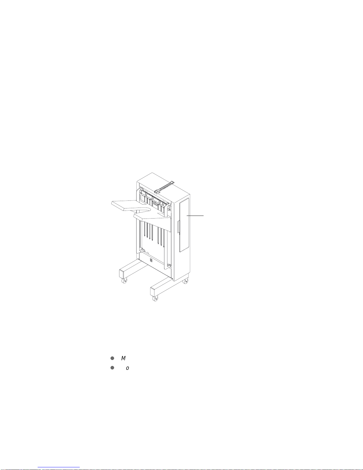
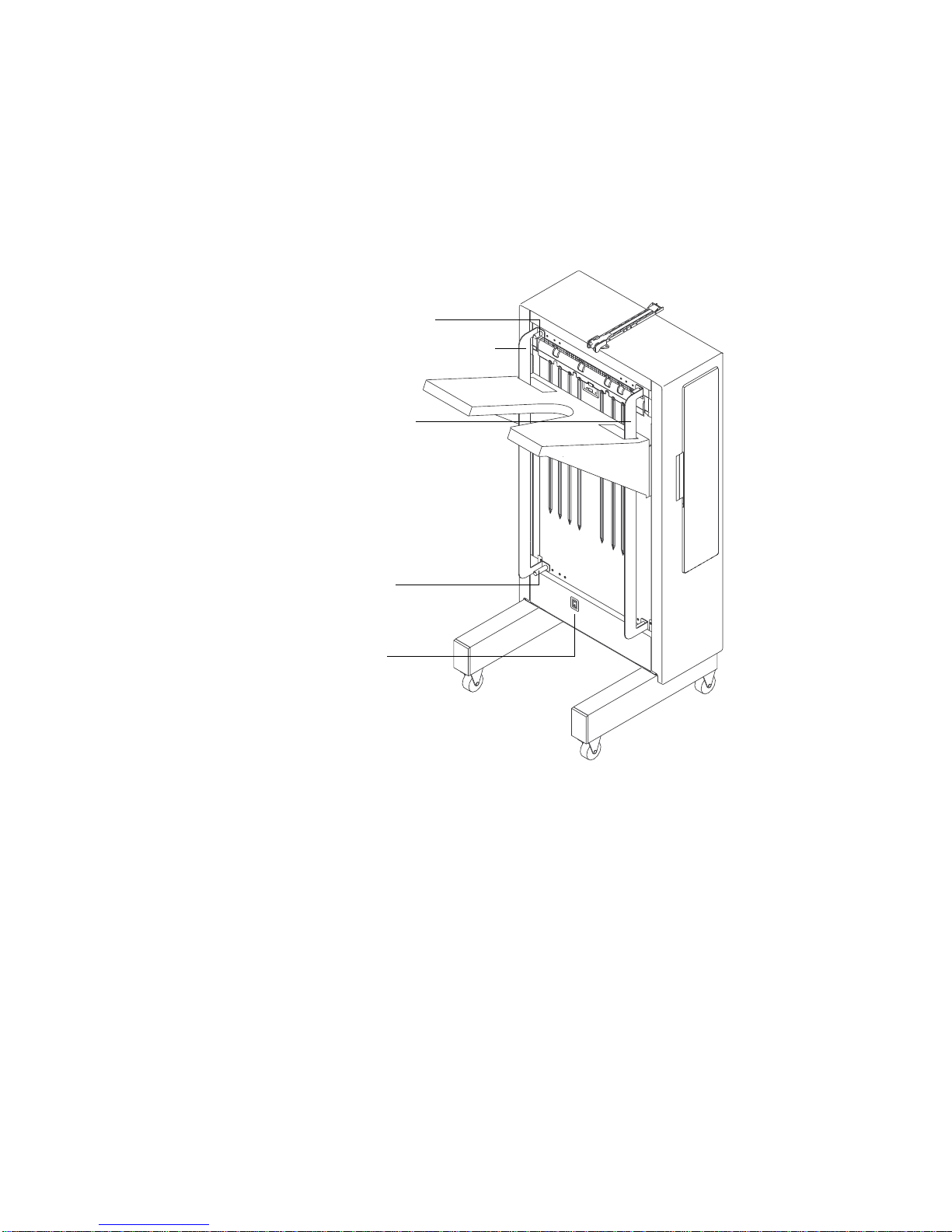
This manual describes how to install and use the 3,000-sheet
High-Capacity Output (HCO) on your Hewlett-Packard 5000 Model
D640 printer. The HCO supports a variety of paper sizes and can
handle up to 40 pages per minute (ppm).
High-capacity output
(up to 3,000 sheets)
Figure 1 High-capacity output for Model D640 printer
Related documents
The information in this manual supplements the following documents:
l
Model D640 Installation Manual
l
Model D640 User Manual
If you’re using the 3,000-sheet HCO, the installation procedures in
this manual replace the HCO installation procedures in the
D640 Installation Manual
Model
.
Chapter 1: Introduction 1
Page 6
Installing the HCO
Note Before you connect the HCO to your printer, make sure the printer
power is turned off.
Unpacking the HCO
The HCO is shipped separately from your printer. The outer carton
contains the HCO and the HCO accessories box. Unpack the HCO
accessories before you unpack the HCO.
WARNING! The HCO weighs over 66 pounds (30 kilograms). To prevent injury,
follow these instructions to unpack the HCO.
To unpack the HCO:
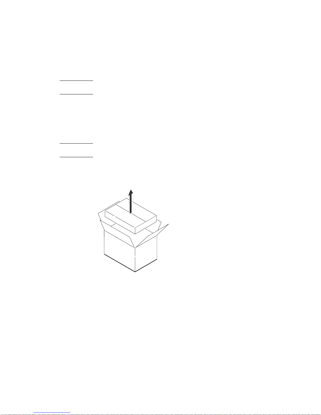
Step 1 Remove the accessories box from the outer carton. See
Figure 2.
Accessories
Figure 2 Unpacking the accessories box
Step 2 Remove the power cable and user manual (near the HCO’s
2 Chapter 1: Introduction
HCO
legs).
Page 7
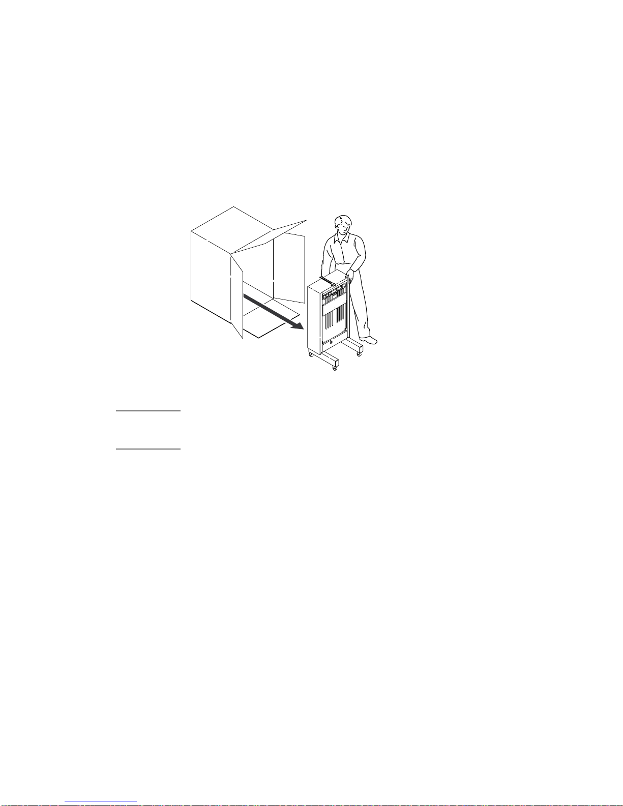
Step 3 Grasp the HCO box and set it upright. Then, remove the
cardboard on top of the HCO.
The HCO’s legs and casters should rest on the bottom of the box.
Step 4 Grasp the top and bottom of the HCO and roll it slowly out of
the box. Make sure the HCO doesn’t fall back as you roll it
from the box. See Figure 3.
HCO
Figure 3 Removing the HCO
CAUTION When you unpack and install the HCO, do not use the paper input guide
on the back of the HCO to move or lift the HCO. You might damage
the guide.
Step 5 Remove the plastic bag and all the packing tape from the
HCO and set the packing material aside.
Don’t forget to open the HCO door and remove the tape on the paper
guides inside the HCO. Otherwise, paper jams will o cc u r .
It’s a good idea to save the packing material in case you need to ship
the HCO in the future.
Chapter 1: Introduction 3
Page 8
Checking the accessories
Before you set up the HCO, use this checklist to make sure you’ve
received all the accessories.
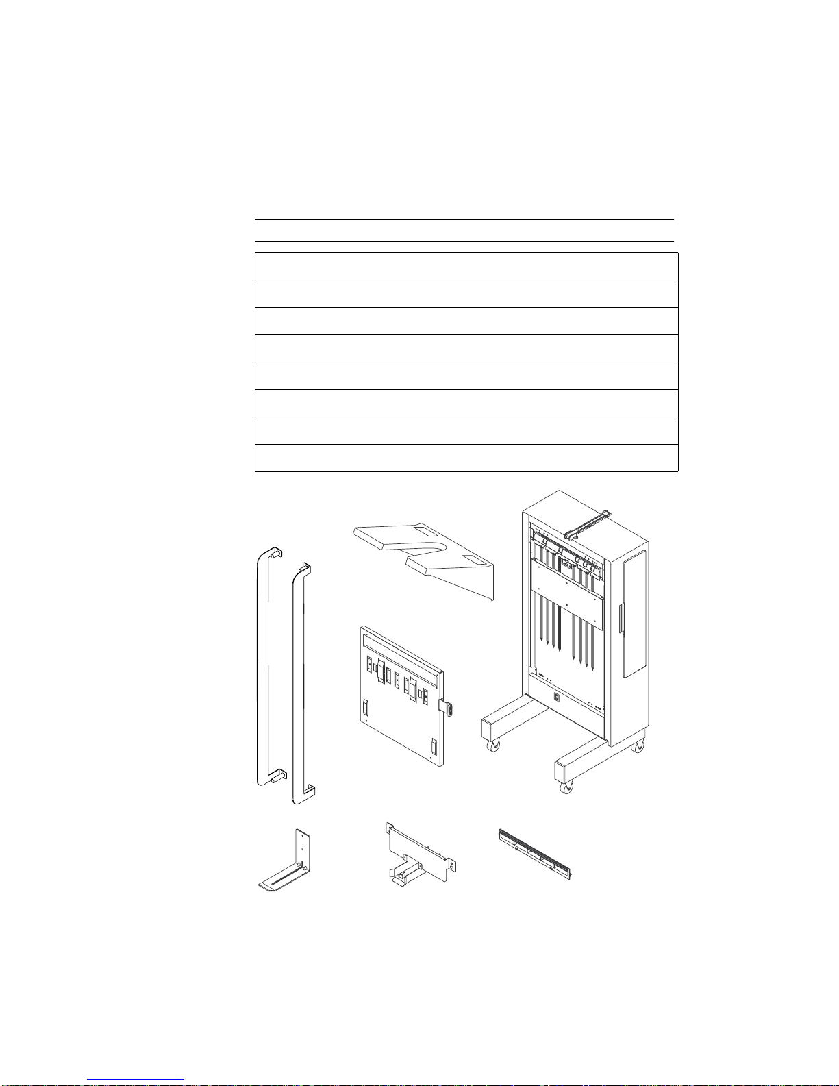
HCO accessories checklist
HCO (and att ac he d interfac e ca bl e)
❑
Tray
❑
Paper guides (with captive knurled screws), quantity = 2
❑
Stopper
❑
Stopper guide (and 2 captive screws)
❑
Paper output guide
❑
Joinin g frame (and 4 captive screws)
❑
Power ca ble, user manual, and scr ew drive r (Not shown below.)
❑
HCOTray
Paper guides
Figure 4 HCO and accessories
4 Chapter 1: Introduction
Stopper
Joining frame
Stopper guide
Paper output guide
Page 9
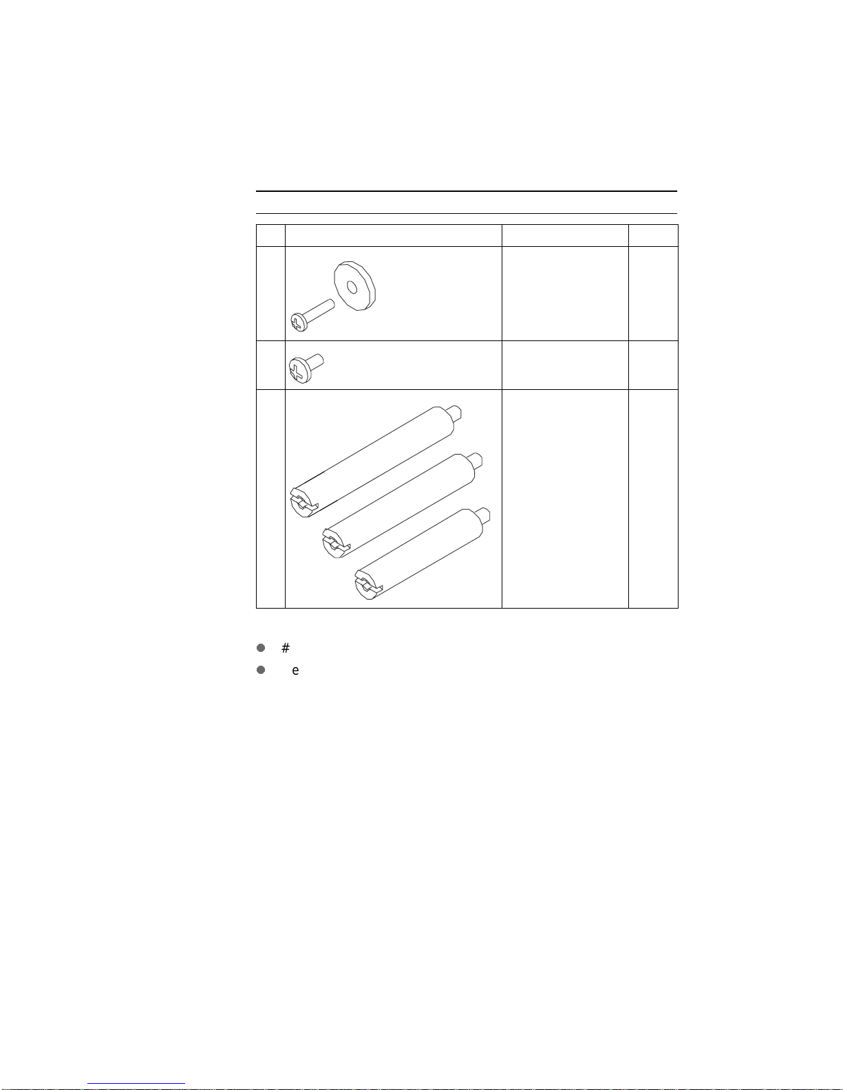
The following table shows the screws and bolts you need to install the
HCO. These are included with the HCO accessories.
Screws and bolts
Examples Description Quantity
❑
Screw and washer
(M4 x 12)
6
❑
❑
Screw
(M4 x 6)
Spacer bolts
(A, B, C)
A
B
C
To install the HCO, you need the following tools:
l
#2 Phillips screwdriver. A screwdriver is included with the HCO.
l
Medium flat-blade screwdriver
2
A = 1
B = 1
C = 2
Chapter 1: Introduction 5
Page 10
Assembling the HCO
The HCO comes with a stopper unit, tray, and paper guides. (See the
checklist on page 4 for a complete list of accessories.)
To attach these accessories to the HCO:
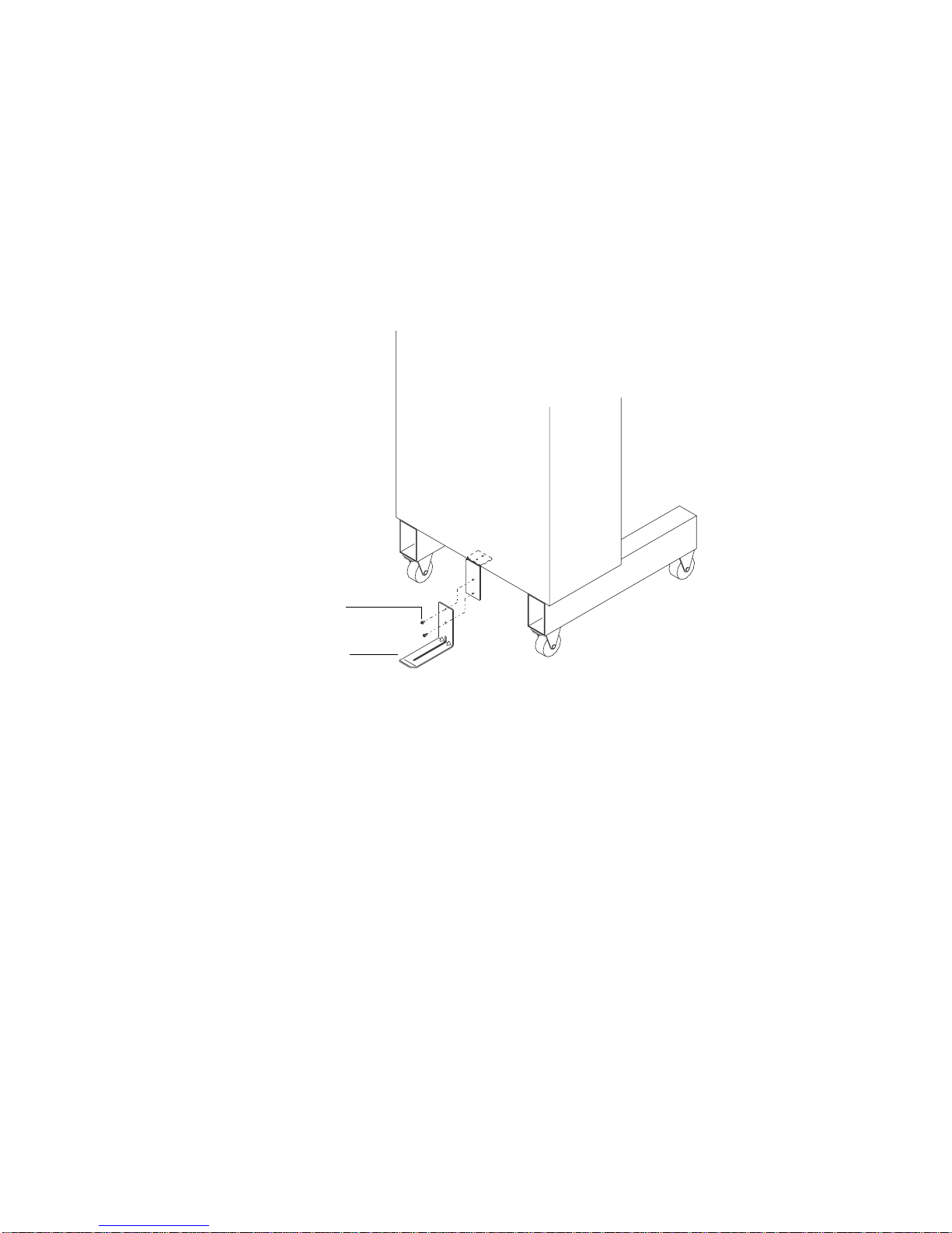
Step 1 Use the two screws (M4 x 6) to attach the stopper to the
lower rear of the HCO. See Figure 5.
.
Screws
M4 x 6
Stopper
Figure 5 Attaching the stopper
Attaching the stopper prevents the HCO from tipping backward when
you install the other HCO accessories.
6 Chapter 1: Introduction
Page 11
Step 2 Slip the hooks on the back of the tray over the tray base. Use
the six screws (M4 x 12) and washers to attach the tray to the
tray base. See Figure 6.
The tray has six drilled holes for the screws.
Tray
Tray base
Washer
Screw
M4 x12
Side view
Tray
Tray base
Figure 6 Attaching the tray to the HCO
Chapter 1: Introduction 7
Page 12
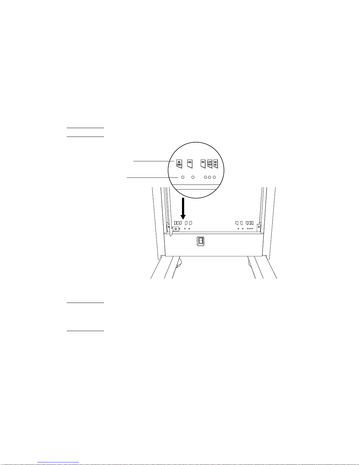
Step 3 Locate the left paper guide and slide it through the left slot of
the paper tray. See Figure 8.
The paper guides are labeled T,L for top left and T,R for top right. The
shorter arm should be on top and the flange should point inward.
Step 4 Locate the paper size markers on the HCO and find the
alignment hole that corresponds to the desired paper size.
See Figure 7.
Note Paper size markers appear on both the top and bottom of the HCO.
Paper size
markers
Alignment
holes
B5
B5
B4LTR
LGL
EXEC
11/17A4A3
B4 LTR
LGL
EXEC
11/17A4A3
Figure 7 Paper size markers
Note When you first install the HCO, Hewlett-Packard recommends you set
the paper guides as far apart as possible (A3/A4 setting). You don’t
need to adjust the guides unless the HCO has paper stacking
problems.
8 Chapter 1: Introduction
Page 13
Step 5 With the paper size markers as a guide, use the captive
knurled screws to attach the paper guide to the HCO.
See Figure 8.
Step 6 Repeat Step 3 through Step 5 for the right paper guide.
Knurled screw
(captive)
Paper guide [T,L]
Paper guide [T,R]
Knurled screw
(captive)
Power switch
Figure 8 Left and right paper guides
Chapter 1: Introduction 9
Page 14
Preparing the printer
After assembling the HCO, prepare the D640 printer for the HCO.
To prepare the printer:
Step 1 Unscrew and remove the paper output cover from the printer.
See Figure 9.
Paper output
cover
Figure 9 Removing the paper output cover
10 Chapter 1: Introduction
Page 15

Step 2 Remove the left screw in the upper cover. See Figure 10.
Left
screw
Figure 10 Removing the left screw in the upper cover
Step 3 Insert spacer bolt (B) into the upper cover hole (where the
screw was). See Figure 11.
Spacer
bolt (B)
Figure 11 Inserting spacer bolt (B)
Spacer bolts are labeled A, B, and C. Make sure you use the correct
bolt (B).
Chapter 1: Introduction 11
Page 16

Step 4 Remove the right screw in the upper cover. See Figure 12.
Right
screw
Figure 12 Removing right screw in upper cover
Step 5 Insert spacer bolt (A) into the hole where the screw was. See
Figure 13.
Spacer bolts are labeled A, B, and C. Make sure you use the correct
bolt (A).
Spacer
bolt (A)
Figure 13 Inserting spacer bolt (A)
12 Chapter 1: Introduction
Page 17

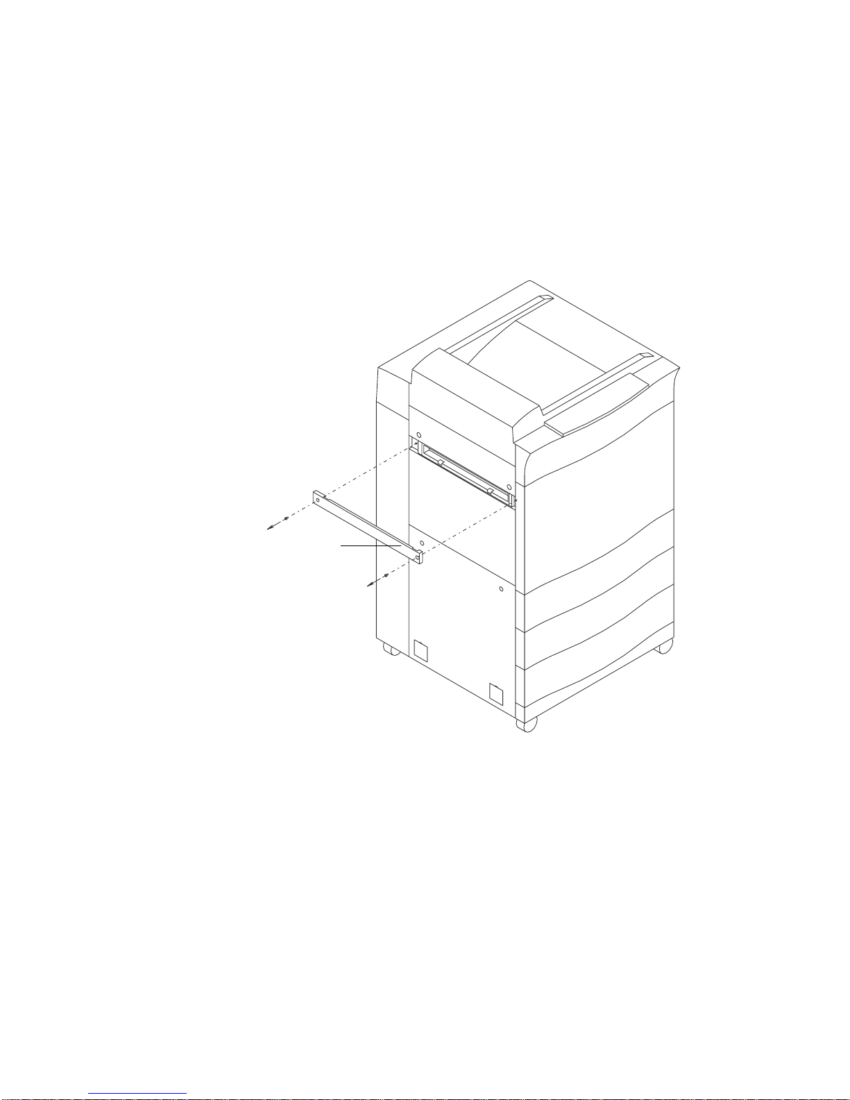
Step 6 Snap the paper output guide in place. See Figure 14.
If you have trouble inserting the paper output guide, make sure the
guide is aligned correctly (parallel to the printer — not tilted up or
down).
Paper
output gu ide
Figure 14 Attaching the paper output guide
Chapter 1: Introduction 13
Page 18

Step 7 Remove the two screws in the lower cover. See Figure 15.
Lower cover
screws (2)
Figure 15 Removing the lower cover screws
Step 8 Insert two spacer bolts (C) into the lower cover holes (where
the screws were). See Figure 16.
Spacer
bolts (C)
Figure 16 Inserting spacer bolts (C)
14 Chapter 1: Introduction
Page 19

Spacer bolts are labeled A, B, and C. Make sure you use the correct
bolt (C).
Step 9 Use a small, flat-bladed screwdriver to pop out the two small,
square panels from the lower cover of the printer. See
Figure 17.
Square panels
Figure 17 Removing square panels
Chapter 1: Introduction 15
Page 20

Step 10 Use two captive screws to install the stopper guide where
the square panels were located. See Figure 18.
Figure 18 Attaching the stopper guide
16 Chapter 1: Introduction
Page 21

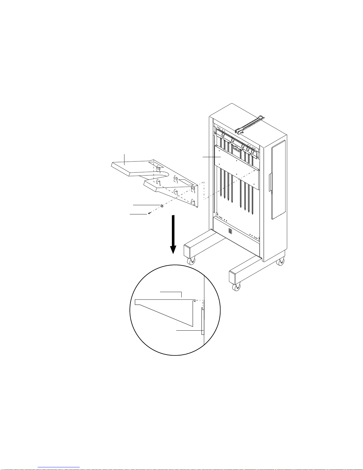
Step 11 Use the four captive screws on the joining frame to attach
the joining frame to the spacer bolts. See Figure 19.
Figure 19 Attaching the joining frame
Chapter 1: Introduction 17
Page 22

Connecting the HCO to the printer
After assembling the HCO and preparing the printer, you’re ready to
attach the HCO to the printer.
To connect the HCO to the printer:
Step 1 When connecting the HCO, lift the HCO a little to make sure
the connecting pin on the stopper guide is aligned with the
stopper hole on the HCO. See Figure 20.
Side view
Connecting pin
Figure 20 Aligning the stopper and stopper guide
18 Chapter 1: Introduction
Stopper Stopper
guide
Page 23

Step 2 Push the HCO against the printer as shown in Figure 21.
The two metal pins on the back of the HCO are connected to the
corresponding holes in the joining frame and the printer latch is
engaged.
Latch lever
Metal pin
Figure 21 Connecting the HCO
Note To disconnect the HCO from the printer, pull the latch lever towards
you and move the HCO away from the printer.
Connecting cables and powering up
After the HCO and printer are attached, you’re ready to connect the
interface cable and power cable.
Step 1 Plug the interface cable from the HCO into the connector on
the back of the printer. See Figure 22.
The connector is located at the back of the printer near the bottom.
Chapter 1: Introduction 19
Page 24

Top view
Side view
Interface
connector
Figure 22 Connecting the interface cable and power cable
Step 2 Plug the socket end of the power cable into the power cable
receptacle on the HCO. See Figure 22.
Step 3 Plug the other end of the power cable into a grounded outlet.
Step 4 Turn on the HCO power switch.
The power switch is on the lower front of the HCO. See Figure 8. It
takes a few seconds for the HCO to perform power-up diagnostics.
20 Chapter 1: Introduction
Int erf ace ca ble
Power cable
socket
Page 25

Configuring the HCO
After you power up the HCO and check the connection, you’re ready
to configure your printer for the HCO.
To configure the HCO:
Step 1 Power up the printer.
If the HCO is connected properly, you should see an HCO icon on the
printer’s control panel.
HCO icon
Ready - - free
JUN 18 05:32.23
PCL
Online
Offline
Offline
Custom Menu Test PapSize
600dpi
LTR
LGR
LTR
LTR
If the HCO icon doesn’t appear, verify the following:
l
the HCO power switch is on.
l
the printer is connected to the HCO.
l
the interface cable is connected.
Step 2 On the printer control panel, press the Menu button and
select Printi ng .
Menu
Online
Online
Printing
Configuration
PCL
Comms
Maintenance
Note For more information about using menus on the D640 printer, see t he
Model D640 User Manual
.
Step 3 Open the Printing menu and select outbin.
Online
Online
Printing
copies = 1
intray = tray1
paper
outbin
duplex = OFF
binding = LONGEDGE
= auto
= UPPER
Chapter 1: Introduction 21
Page 26

Step 4 Highlight either HCO-FACEDOWN or HCO-FACEUP and
press Select.
Printing.outbin
Online
Online Select
= UPPER
= HCO-FACEDOWN
= HCO-FACEUP
Step 5 Press Save.
The control panel changes to show that the HCO is set to act as the
printer’s main output tray.
HCO icon Paper path
Ready - - free
JUL 25 05:32.23
PCL
Offline
Online
Offline
Custom Menu Test PapSize
600dpi
LTR
LTR
LTR
LTR
Congratulations! You’ve successfully installed the 3,000-sheet HCO.
For more information on using the HCO, see Chapter 2.
22 Chapter 1: Introduction
Page 27

Using the HCO
2
This chapter contains information on how to adjust the paper stopper
and paper guides on the HCO and clear paper jams. It also includes a
list of HCO messages that may appear on the printer’s control panel.
Adjusting the paper stopper and guides
Paper stopper
Paper guide
(left)
Paper guide
(right)
Figure 23 Paper stopper and paper guides
Chapter 2: Using the HCO 23
Page 28

Adjusting the paper stopper
After you install the 3,000-sheet HCO, adjust the paper stopper to fit
the size of paper you’re using.
To adjust the paper stopper:
Step 1 Locate the paper stopper on top of the HCO and position it as
shown in Figure 23.
Step 2 Locate the paper size markers on the stopper and slide the
paper stopper to the desired paper size.
Align this marker with
the desired paper size.
LGL
EXEC
A4, LTR
B5
Figure 24 Paper size markers on the paper stopper
Paper size choices are: Legal, Executive, B5, and A4/LTR.
Note If you’re printing on A3 or Ledger paper, you don’t need the paper
stopper. Lift the paper stopper up and out of the way.
24 Chapter 2: Using the HCO
Page 29

Adjusting the paper gui des
,,,,
,,
,,,
,
,,,,,
,,,,
,,
Note Hewlett-Packard recommends you set the paper guides as far apart
as possible (A3/A4 setting). You don’t need to adjust the guides unless
the HCO has paper stacking problems.
To adjust the paper guides:
Step 1 Locate the paper guides on the HCO.
There are two paper guides, one on each side of the HCO.
Step 2 Release a guide by unscrewing the knurled screws that
connect the guide to the top and bottom of the HCO.
Top of HCO Bottom of HCO
B5
B5
B4LTR
LGL
EXEC
11/17A4A3
B4 LTR
LGL
EXEC
11/17A4A3
Figure 25 Releasing a paper guide
Step 3 Use the paper size markers at the top and bottom of the HCO
to reposition the guide to the desired paper size.
Figure 26 Paper size markers
Chapter 2: Using the HCO 25
Page 30

Step 4 Tighten the knurled screws to reattach the guide to the
printer.
Step 5 Repeat this procedure for the guide on the other side of the
HCO.
Make sure you select the same paper size for each guide.
Clearing an HCO paper jam
If the HCO has a paper jam, you’ll see an message on the printer’s
control panel. For example:
HCO jam 1
PCL
Cen
Offline
Offline
Offline
Menu End
600dpi
LTR
LTR
LGL
Clearing the HCO
To clear a paper jam in the HCO:
Step 1 Open the front door of the printer and remove any jammed
paper in the reversing area. See Figure 27.
Figure 27 Clearing the reversing area
26 Chapter 2: Using the HCO
Page 31

Step 2 Open the HCO door and locate HCO knob 1. See Figure 28.
Step 3 Rotate the knob counterclockwise to move paper from the
HCO input area to the lower section.
HCO knob 1
Figure 28 Rotating HCO knob 1
Step 4 Pull back lever 2 and remove any paper you find. See
Figure 29.
Lever 2
Figure 29 Pulling back lever 2
Chapter 2: Using the HCO 27
Page 32

Lever 1
Step 5 If jammed paper is not visible, lift HCO lever 1 to see if any
paper is jammed near the top of the HCO. See Figure 30.
Figure 30 Lifting lever 1
Step 6 Rotate knob 1 to move any paper into view. See Figure 28.
Step 7 Remove any paper you find.
Note When you check for jams, make sure you return the HCO levers to their
proper closed positions. Otherwise, more jams will occur .
Separating the HCO from the printer
If jammed paper is still not visible, paper may be jammed between the
HCO and the printer. You’ll need to separate the HC O from the
printer and check for jams.
28 Chapter 2: Using the HCO
Page 33

To separate the HCO from the printer:
Step 1 Pull the HCO latch lever towards you and move the HCO
away from the printer. See Figure 31.
Latch lever
Figure 31 Separating the HCO from the printer
Move the HCO as far as the stopper that connects the HCO to the
printer allows (about 1 inch).
Step 2 Check for any paper jammed between the HCO and the
printer.
If no other paper jam messages appear on the printer’s control panel,
you’re ready to reattach the HCO and resume printing.
If the control panel still shows the same jam, search the area again. If
the control panel shows another type of jam, search the area
indicated.
Chapter 2: Using the HCO 29
Page 34

Messages
HCO Messages
The following is a list of HCO messages that may appear on the
printer’s control panel
Message Remedy Message type
HCO jam1
HCO jam 2
HCO cover open Make sure the HCO cover is closed, the HCO
Stack fault – Call
engineer
Error code: SVC D8
HCO stacker alarm
Refer to “Clearing an HCO paper jam” on
page 26 to clear the jam.
power switch i s on, and the HCO is connected
to the printer.
1.
Important:
representative, verify the following:
l
the HCO cover is closed.
l
the HCO power switch is on
l
the HCO is connected to the printer and
the interface cable is connected.
2. Restart the printer and the HCO.
If the message still appears, call your HP
service repres entative.
1. Verify the following:
l
the HCO interface ca ble is connected to
the printer.
l
the HCO’s power cable is plug ged int o a
working power outlet.
l
The HCO’s power switch is on.
2. Press clear.
If the error code retu rns, call your HP service
representative.
3. To continue printing without the HCO,
disconnect the HCO interface cable and
restart the pr int e r.
Before you call your HP servic e
Paper jam message
Printing stops until the
jam is cleared.
Error me ssa ge
stops until the error is
cleared.
C
all engineer message
This message may
appear incorrectly, when
the HCO is
disconnected from the
printer.
Call engineer message
Stops the printer and
takes it o ffl in e .
a
:
: Printing
:
:
30 Chapter 2: Using the HCO
Page 35

HCO Messages
Message Remedy Message type
HCO not ready 1. Verify the following:
l
the HCO interface ca ble is connected to
the printer.
l
the HCO’s power cable is plug ged int o a
working power outlet.
l
The HCO’s power switch is on.
2. Press clear.
If the error message returns, cycle power on
the printer and HCO. The HCO takes a few
seconds to perfor m power-up diagnostics.
3. If the error message ret urns, call your HP
service repres entative.
a. For more information about types of messages, se e the
D640 User Manual.
Call engineer message
Stops the printer and
takes it o ffl in e .
a
:
Chapter 2: Using the HCO 31
Page 36

32 Chapter 2: Using the HCO
Page 37

Specifications,
3
Regulatory Information
This chapter contains specifications and regulatory information for the
3,000-sheet HCO.
Specifications
Note The specifications in this document are preliminary and subject to
change.
HCO paper handing specifications
HCO paper handling specifications
Item Specifications
Processing Speed 40 ppm
Paper Size Letter, Legal, Ledger, Executive, A3, A4, A5,
B4(JI S ), B 5 (ISO)
Type Plain paper, Label paper , Transparency, Bond
paper, Pre-punched paper, 64 to 90g/m2
Paper capacity 3,000 sheets (75g/ m2 )
Chapter 3: Specifications, Regulatory Information 33
Page 38

HCO physical specifications
HCO physical specifications
Item Specifications
Dimensions Width 16.1 inches (408 mm)
Depth 17.4 inches (446 mm)
Height 36.0 inches (913 mm)
Service area Front 25.6 inc hes (650 mm)
Back 33.5 inches (850 mm)
Right 33.5 inc hes (850 mm)
Weight 66 pounds (30 kilograms)
HCO electrical specifications
HCO electrical specifications
Item Specifications
Input power Vo lt age 100 to 120 VAC ± 10%
200 to 240 VAC
Phase Single-phase
± 10%
Frequency 50/60 Hz
Power consumption 180 VA or less than during operation
Heat production 95 kcal per hour (380 BTU/hr)
HCO environmental specificat ions
HCO environmental specifications
Ambie nt condition Opera t ing Non-op erating
Temperature 15 to 35 °C -40 to +70 °C
Humidity 20 to 80% RH
(no condensation)
40 to 60% RH optimal
Temperature and
humidity gradients
34 Chapter 3: Specifications, Regulatory Information
15 °C per hour or less and 30% RH per day or less
(no condensation)
20 to 80% RH
(no condensation)
40 to 60% RH optimal
Page 39

Safety and regulatory information
For safety and regulatory information on the 3,000 page HCO, refer to
the safety and regulatory information provided in the
Manual
Australia EMC
This symbol indicates compliance with Australian standard AS/NZS
3548:1995.
. In addition, the following regulatory information applies.
D640 User
Chapter 3: Specifications, Regulatory Information 35
Page 40

HP Declaration of Conformity
DECLARATION OF CONFORMITY
according to ISO/IE C Guide 22 and EN 45014
Manufacturer’s name: Hewlett-Packard Company
Manufacturer’s address: 19420 Homestead Road
Cupertino, California 95014, USA
declares that the product
Product name: 3000-page HCO for Model D640 Printer
Model number: C5638A
Product options: n/a
conforms to the following Product Specifications:
Safety: IEC 950:1991 + A1, A2, A3 / EN 60950:1992 + A1, A2
EMC: CISPR 22: 1993 / EN 55022:1994 Class A
EN 50082-1:1992
IEC 801-2:1991 / prEN 55024-2 (1992) 4kV CD, 8kV AD
IEC 801-3:1984 / prEN 55024-3 (1991) 3 V/m
IEC 801-4:1988 / prEN 55024-4 (1992) 1 kV Power Lines
0.5 kV Signal Lines
Supplementary Information:
The product herewith complies with the requirements of the EMC Directive
(89/336/EEC) and the Low Voltage Directive (73/23/EEC) and carries the
CE marking accordingly:
The product was evaluated and tested with the C5620B (HP Model D640)
printer.
September 1, 1997 Office of the Quality Manag er
European Contact: Your local Hewlett-Packard Sales and Service Office or Hewlett-Packard GmbH,
Department HQ-TRE, Herrenberge r Straße 130, D-71034 Böbli ngen (FAX:+ 49-70 31-1 4-314 3)
36 Chapter 3: Specifications, Regulatory Information
Page 41

Index
A
A3/A4 pa pe r set t in gs 8
See also
accessories
checking 4
unpack i ng 2
adjust in g
paper guides 25–26
paper stopper 24
aligning
paper output guide 13
alignment holes, for paper sizes 8
assembling, HCO 6–9
attaching
joining frame 17
paper guides 8
paper output guide 13
stopper 6
stopper guide 16
tray 7
Australia EMC certification 35
paper siz es
B
buttons
Menu 21
Save 22
C
certific ation, Aus tra lia EMC 35
checking, accessories 4
clear ing, paper jams 26–29
configuring
printer for HCO 21– 22
connec ting
HCO to printer 18–20
interfac e ca ble 19
power ca bl e 20
connecting pin, on stopper
guide 18
control panel 21, 29, 30
Cover open message 30
D
Declaration of Conformity 36
diagno stics, power-up 20, 31
dimensions, of HCO 34
disconnecting, HCO from
printer 19
E
error messages 30
F
flange, on paper guide 8
front door, of printer 26
G
grounded outlet 20
H
HCO
connecting to printer 18–20
error messages 30
knobs and levers 27
powering up 20
printing without 30
separating from printer 19,
28–29
specifications 33–34
unpacking 2–3
using 23–31
HCO door 3, 27
HCO icon, on control panel 21
HCO input area 27
HCO, assembling 6–9
HCO-FACEDOWN setting 22
HCO-FACEUP setting 22
heat production 34
See
high capacity output.
HP Declaration of Conformity 36
humidity specifications 34
HCO
I
indicator, paper path 22
inser ting, spac er bol ts 11, 12, 14
installing.
interface cable 4, 30
interface connector 20
See
attaching
connecting 19
See also
interfac e ca ble
J
Jam messages 30
See
jams.
joining frame 4
paper jams
attaching 17
K
knobs a nd levers, inside HCO 27,
28
knurled screws 4, 9, 25
L
latch lever.
levers and knobs, inside HCO 27
See
printer latch
M
markers, paper size 8, 24, 25
Menu button 21
menus, Printing 21
N
Not ready message 31
O
outbin setting 21
output tray, using HCO as 22
Index 37
Page 42

P
packing material 3
pages pe r min ute 1, 33
paper capacity 33
paper guides 4, 23
adjusting 25– 26
attaching 8
paper input guide 3
paper jams 30
clearing 26–29
preventing 3, 28
paper output cover, removing 10
paper output guide 4
attaching 13
paper path indicator 22
paper sizes 1, 8, 24, 25, 33
paper stacking problems 8
paper stopper 23
adjusting 24
pins, on back of HCO 19
power ca bl e 2, 4
connec ti ng 20
See
power cord.
power requirements 34
power switch 9, 20, 30
power-up diagnostics 20, 31
preparing, printer for HCO 10–17
preventing, paper jams 3
printer
configuring for HCO 21–22
powering up 21
preparing for HCO 10–17
separating from HCO 28–29
printer latch 19, 29
Printing menu 21
printing, without HCO 30
problems
error messages 30
stacking paper 8, 25
processing speed 33
power ca bl e
R
regula to ry in for m a tio n 35
related documents 1
removing
paper output cover 10
screws 12, 14
square panels 15
upper cover 11
reversing area, clearing paper
jams in 26
S
safety information 35
Save button 22
screwdriver 5, 15
screws 5
knurled 9, 25
lower cover 14
M4 x 12 7
M4 x 6 6
on joining frame 17
on stopper guide 16
upper cover 12
servic e area specifications 34
settings
HCO-FACEDOWN 22
HCO-FACEUP 22
outbin 21
paper size 8
spacer bolts 5
inserting 11, 12, 14
specifications 33–34
square panels, removing 15
Stack fault message 30
Stacker alarm message 30
stacking problems.
stacking problems
stopper 4, 29
attaching 6
stopper guide 4
attaching 16
connecting pin 18
SVC D8 error message 30
See
paper
T
tempera ture specifications 34
tipp ing, preventing 6
tray 4
attaching 7
tray base 7
U
unpacking
accessories 2
HCO 2– 3
upper cover, removing 11
user manual 2, 4
W
washers 5, 7
weight specifications 2, 34
38 Index
Page 43

READER COMMENT SHEET
System Peripherals Operation
D640 Cut Sheet Printer 3,000-Sheet HCO
Manual Part Number C5638-90001
October 1997
A reader comment sheet helps us improve the accuracy and readability of this document. It
also gives you a way to make sugges tions and recommend improvements to the product.
Serious errors, such as technical inaccuracies that may render a program or mechanical device
inoperative, should be reported immediately to your Hewlett Packard Response Center or
directly to a Support Engineer. This ensures that such problems are addre ssed a s quickly as
possible.
Editorial suggestions (please include page, table, and figure numbers):
Recommendations (attach additional information, if needed):
Name: Date:
Job Title: Telephone:
Company:
Address:
Hewlett-Packard has the right to use submitted suggestions without obligation, with all such
ideas becoming the property of Hewlett-Packard.
Page 44

 Loading...