

Page 1

Service Handbook
C Class
Models
C100, C110, C160L, C160,
C180, C200, C240 and C360
HP Part No. A4200-90042
Edition E1298
Printed in U.S.A.
Page 2

Hewlett-Packard Co. 1998
Printing History
First Printing: August 1998
UNIX is a registered trademark in the United States and other
countries, licensed exclusively through X/Open Company Limited.
NOTICE
The information contained in this document is subject to change
without notice.
HEWLETT-PACKARD WARRANTY STATEMENT
HP PRODUCT DURATION OF WARRANTY
C160/C180/C200/C240/C360 one year
1. HP warrants HP hardware, accessories and supplies against
defects in materials and workmanship for the period specified
above. If HP receive notice of such defects during the warranty
period, HP will, at its option, either repair or replace products
which prove to be defective. Replacement products may be either
new or like-new.
2. HP warrants that HP software will not fail to execute its programming instructions, for the period specified above, due to
defects in material and workmanship when properly installed and
used. If HP receives notice of such defects during the warranty
period, HP will replace software media which does not execute its
programming instructions due to such defects.
3. HP does not warrant that the operation of HP products will be
uninterrupted or error free. If HP is unable, within a reasonable
time, to repair or replace any product to a condition as warranted,
customer will be entitled to a refund of the purchase price upon
prompt return of the product.
4. HP products may contain remanufactured parts equivalent to
new in performance or may have been subject to incidental use.
ii
Page 3

5. The warranty period begins on the date of delivery or on the
date of installation if installed by HP. If customer schedules installation or causes installation by HP to be delayed more than 30 days
after delivery, warranty begins on the 31st day from delivery.
6. Warranty does not apply to defects resulting from (a) improper
or inadequate maintenance or calibration, (b) software, interfacing,
parts or supplies not supplied by HP, (c) unauthorized modification
or misuse, (d) operation outside of the published environmental
specifications for the product, or (e) improper site preparation or
maintenance.
7. TO THE EXTENT ALLOWED BY LOCAL LAW, THE
ABOVE WARRANTIES ARE EXCLUSIVE AND NO OTHER
WARRANTY OR CONDITION, WHETHER WRITTEN OR
ORAL, IS EXPRESSED OR IMPLIED AND HP SPECIFICALLY DISCLAIMS ANY IMPLIED WARRANTIES OR CONDITIONS OF MERCHANTABILITY, SATISFACTORY
QUALITY, AND FITNESS FOR A PARTICULAR PURPOSE.
8. HP will be liable for damage to tangible property per incident up
to the greater of $300,000 or the actual amount paid for the product that is the subject of the claim, and for damages for bodily
injury or death, to the extent that all such damages are determined
by a court of competent jurisdiction to have been directly caused
by a defective HP product.
9. TO THE EXTENT ALLOWED BY LOCAL LAW, THE REMEDIES IN THIS WARRANTY STATEMENT ARE CUSTOMER'S SOLE AND EXCLUSIVE REMEDIES. EXCEPT AS
INDICATED ABOVE, IN NO EVENT WILL HP OR ITS SUPPLIERS BE LIABLE FOR LOSS OF DATA OR FOR DIRECT,
SPECIAL, INCIDENTAL, CONSEQUENTIAL (INCLUDING
LOST PROFIT OR DATA), OR OTHER DAMAGE, WHETHER
BASED IN CONTRACT, TORT, OR OTHERWISE.
FOR CONSUMER TRANSACTIONS IN AUSTRALIA AND
NEW ZEALAND: THE WARRANTY TERMS CONTAINED IN
THIS STATEMENT, EXCEPT TO THE EXTENT LAWFULLY
PERMITTED, DO NOT EXCLUDE, RESTRICT OR MODIFY
AND ARE IN ADDITION TO THE MANDATORY STATUTORY RIGHTS APPLICABLE TO THE SALE OF THIS PRODUCT TO YOU.
iii
Page 4

This document contains proprietary information that is protected
by copyright. All rights reserved. No part of this document may be
photocopied, reproduced or translated to another language without
the prior written consent of Hewlett-Packard Company.
RESTRICTED RIGHTS LEGEND. Use, duplication, or disclosure by government is subject to restrictions as set forth in subdivision (c) (1) (ii) of the Rights in Technical Data and Computer
Software Clause at DFARS 252.227.7013. Hewlett-Packard Co.,
3000 Hanover St., Palo Alto, CA 94304.
10 9 8 7 6 5 4 3 2 1
iv
Page 5

Safety and Regulatory Statements
Safety and Regulatory Statements
This section contains safety and regulatory statements
pertaining to the C100, C110, C160L, C160, C180,
C200, C240 and C360 workstations. It provides information on the following topics:
• Special video configuration statements
• Emissions regulations
• Emissions regulations compliance
• Datacom users statement
• Acoustics
• Electrostatic discharge (ESD) precautions
• Safety statement
• Laser safety statements
• Warnings and cautions
v
Page 6

Special Video Configuration Statements
Special Video Configuration Statements
The following statements apply only to those applications which include a cable connected to the S-Video
connector on the A4248A card. No modification to the
regulatory statements is necessary for applications
which include cables connected to other connectors on
the card but not to the S-Video connector.
For EN55022 or CISPR 22 Applications:
WARNING: This is a Class A product. In a domestic environment
this product may cause radio interference in which
case the user may be required to take adequate
measures.
For FCC Applications:
NOTICE: This equipment has been tested and found to
comply with the limits for a Class A digital device,
pursuant to part 15 of the FCC rules. These limits
are designed to provide reasonable protection
against harmful interference when the equipment
is operated in a commercial environment. This
equipment generates, uses, and can radiate radio
frequency energy and, if not installed and used in
accordance with the instruction manual, may cause
harmful interference to radio communications.
Operation of this equipment in a residential area is
likely to cause harmful interference in which case
the user will be required to correct the interference
at his own expense.
vi
Page 7

Models C160L/C160/C180/C200/C240/C360 Emissions Regulations
Models C160L/C160/C180/C200/C240/
C360 Emissions Regulations
Federal Communications Commission (FCC)
This equipment has been tested and found to comply
with the limits for a Class B digital device, pursuant to
part 15 of the FCC Rules and the Canadian Department of Communications. These limits are designed to
provide reasonable protection against harmful interference in a residential installation. This equipment generates, uses, and can radiate radio frequency energy
and, if not installed and used in accordance with the
instructions, may cause harmful interference to radio
communications. However, there is no guarantee that
interference will not occur in a particular installation.
If this equipment does cause harmful interference to
radio or television reception (determined by turning
the equipment off and on), you can correct the interference by one or more of the following measures:
• Reorient or relocate the receiving antenna.
• Increase the separation between the equipment and the
receiver.
• Connect the equipment into an outlet on a circuit different from that to which the receiver is connected.
• Ask the dealer or an experienced radio/television technician for help.
Hewlett-Packard’s system certification tests were conducted with HP-supported peripheral devices and HP
shielded cables, such as those you receive with your
vii
Page 8
Models C160L/C160/C180/C200/C240/C360 Emissions Regulations
computer. Changes or modifications not expressly
approved by Hewlett-Packard could void the user’s
authority to operate the equipment.
Operation of this device is subject to the following
conditions:
• This device may not cause harmful interference.
• This device must accept interference received, including
interference that may cause undesired operation.
• Cables used with this device must be properly shielded to
comply with the requirements of the FCC.
VCCI Class B ITE (Japan)
Korea RRL (EMI Class A)
viii
Page 9

Models C100/C110 Emissions Regulations
Models C100/C110 Emissions
Regulations
Federal Communications Commission (FCC)
This equipment has been tested and found to comply
with the limits for a Class A digital device, pursuant to
part 15 of the FCC Rules and the Canadian Department of Communications. These limits are designed to
provide reasonable protection against harmful interference in a residential installation. This equipment generates, uses, and can radiate radio frequency energy
and, if not installed and used in accordance with the
instructions, may cause harmful interference to radio
communications. However, there is no guarantee that
interference will not occur in a particular installation.
If this equipment does cause harmful interference to
radio or television reception (determined by turning
the equipment off and on), you can correct the interference by one or more of the following measures:
• Reorient or relocate the receiving antenna.
• Increase the separation between the equipment and the
receiver.
• Connect the equipment into an outlet on a circuit different from that to which the receiver is connected.
• Ask the dealer or an experienced radio/television technician for help.
Hewlett-Packard’s system certification tests were conducted with HP-supported peripheral devices and HP
shielded cables, such as those you receive with your
ix
Page 10
Models C100/C110 Emissions Regulations
computer. Changes or modifications not expressly
approved by Hewlett-Packard could void the user’s
authority to operate the equipment.
Operation of this device is subject to the following
conditions:
• This device may not cause harmful interference.
• This device must accept interference received, including
interference that may cause undesired operation.
• Cables used with this device must be properly shielded to
comply with the requirements of the FCC.
VCCI Class 1 ITE
x
Page 11

Emissions Regulations Compliance
Emissions Regulations Compliance
Any third-party I/O device installed in HP system(s)
must be in accordance with the requirements set forth
in the preceding Emissions Regulations statements. In
the event that a third-party noncompliant I/O device is
installed, the customer assumes all responsibility and
liability arising therefrom.
Acoustics
Regulation On Noise Declaration
For Machines -3. GSGV
Lpa <70dB
Lpa<70dB
operator position am Arbeitsplatz
normal operation normaler Betrieb
per ISO 7779 nach DIN 45635 T.19
xi
Page 12

Electrostatic Discharge (ESD) Precautions
Electrostatic Discharge (ESD)
Precautions
Electrostatic charges can damage the integrated circuits on printed circuit boards. To prevent such damage from occurring, observe the following precautions
during board unpacking and installation:
• Stand on a static-free mat.
• Wear a static strap to ensure that any accumulated electrostatic charge is discharged from your body to ground.
• Connect all equipment together, including the static-free
mat, static strap, routing nodes, and peripheral units.
• Keep uninstalled printed circuit boards in their protective
antistatic bags.
• Handle printed circuit boards by their edges, once you
have removed them from their protective antistatic bags.
Safety Statement
This equipment conforms to the following safety standards:
• UL 1950
• CSA 950
• IEC 950
• EN 60950
xii
Page 13

Laser Safety Statement (U.S.A. Only)
Laser Safety Statement (U.S.A. Only)
The CD ROM mass-storage system is certified as a
Class-1 laser product under the U.S. Department of
Health and Human Services (DHHS) Radiation Performance Standard according to the Radiation Control
for Health and Safety Act of 1968.
This means that the mass-storage system does not produce hazardous laser radiation. Because laser light
emitted inside the mass-storage system is completely
confined within protective housings and external covers, the laser beam cannot escape from the machine
during any phase of user operation.
xiii
Page 14
Warnings and Cautions
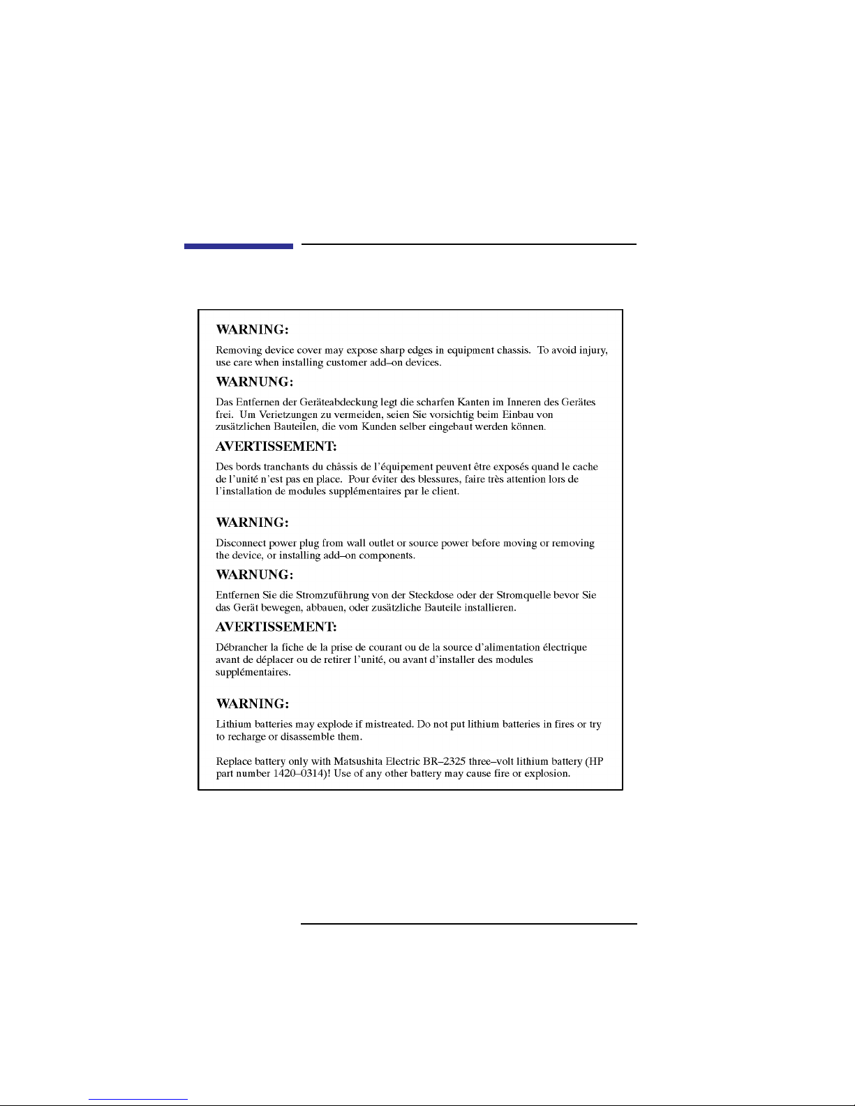
Warnings and Cautions
xiv
Page 15

Contents
1 Product Information
Product Description 3
System Unit Front Panel Controls 6
System Power Switch 6
Power LED 7
System LEDs 7
Audio Controls 8
Storage Device Controls and Features 8
CD-ROM Drive 9
DDS Tape Drive 11
Floppy Disk Drive 13
System Unit Rear Panel Connectors 14
Security Loop 15
Audio Connectors 16
Keyboard and Mouse Connectors 19
PS/2 Keyboard and Mouse Connectors 19
ITF Keyboard Connector 19
HP Parallel I/O Connector 19
802.3 Network Connectors 19
Serial Input/Output Connectors 20
SCSI Connectors 21
TOC Button 21
Power Cord Connector 21
Monitors 22
Keyboards 23
Keyboard Differences 23
Pointing Devices 27
xv
Page 16

Contents
Operating System Overview 28
2 Environmental/Installation/PM
Environmental Specifications 31
Installation 33
Preventive Maintenance 33
3 Configuration
Workstation Configurations 37
FRU Configurations 38
Internal Storage Configurations 38
Allowable Memory Configurations 50
Monitor-Type Selection 53
Changing the Console to External Terminal 53
Graphics Configurations 54
Special Video Configuration Statements
for all Systems 54
For EN55022 or CISPR 22 Applications: 54
For FCC Applications: 54
Models C100 and C110 55
Models C160 and C180 56
Graphics Paths 56
Graphics Configuration Restrictions 57
Models C160L 59
Graphics Paths 59
xvi
Page 17

Contents
Graphics Configuration Restrictions 60
4 Troubleshooting
Getting Ready to Troubleshoot 63
Dealing with a Boot Failure 68
Searching for Bootable Media 70
Stable Storage 71
Boot Command Notations 71
Supported Boot Paths 72
ISL Environment 72
Selftest Failures 73
Chassis Display Codes 77
Running System Verification Tests 95
Running ODE-Based Diagnostics 97
Troubleshooting the SCSI I/O Board 99
5 Field Replaceable Units
Exchange and Nonexchange Part Numbers 107
FRU Removal and Replacement 115
Storage Tray Assembly 117
Disk Interconnect Board 118
Storage Tray Bezel 119
Disk Filler Panel 120
xvii
Page 18

Contents
Storage Devices 121
Human Interface Board 123
Main Tray Assembly 124
Removing Memory Modules 125
Installing Memory Modules 127
Removing Second Level Cache Modules (C160L) 129
Installing Cache Modules 131
Removing PCI, EISA, and GSC Option Boards 133
EGRAM (Enhanced Graphics RAM) Board 136
CPU Board 138
System Fans 142
Rear Panel 145
I/O Board 146
Determining LAN ID and FDDI ID 147
Removing the I/O Board 148
I/O Extension Board 149
Battery 150
Backplane 151
Power Supply 153
Power Interconnect Board 154
6 Diagrams
System Power 157
System Block Diagram 163
7 Reference
Installation Manual 171
xviii
Page 19

Contents
Service Manuals 171
Reference Manuals 171
8 Service Notes
9 Boot Console Interface Model C100/110
Accessing the Boot Console Interface 179
Boot Console Menus 181
Searching for Bootable Media 184
Resetting the Workstation 186
Displaying and Setting Paths 187
Displaying and Setting the Monitor Type 190
The Monitor Command 190
Displaying the Current Monitor Configuration 193
Setting the Monitor Type 194
Setting the Monitor Type at Power On 197
Changing the Console to External Terminal 198
Displaying the Status of the System I/O 199
Setting the Auto Boot and Auto Search Flags 200
Displaying and Setting Secure Mode 202
Displaying and Setting Fastboot Mode 203
xix
Page 20

Contents
Displaying the LAN Station Address 204
Displaying System Information 205
Displaying PIM Information 206
Configure and Display LAN Settings 207
Stable Storage 209
ISL Environment 210
Invoking ISL from the Boot Console Interface 210
ISL User Commands 211
Updating System Firmware with ODE 213
10 Boot Console Interface Model C160L/160/180/
200/240/360
Accessing the Boot Console Interface 217
Boot Console Menus 219
Searching for Bootable Media 223
Resetting Your Workstation 224
Displaying and Setting Paths 225
Displaying and Setting the Monitor Type 228
The Monitor Command 228
Displaying the Current Monitor Configuration 230
Setting the Monitor Type 231
Setting the Monitor Type at Power On 233
xx
Page 21

Contents
Changing the Console to External Terminal 235
Displaying the Status of the System I/O 236
Setting the Auto Boot and Auto Search Flags 237
Displaying and Setting the Fastboot Mode 239
Displaying the LAN Station Address 240
Configure and Display LAN Settings 241
Displaying System Information 243
Displaying PIM Information 244
Stable Storage 245
ISL Environment 246
Invoking ISL from the Boot Console Interface 246
ISL User Commands 247
Updating System Firmware with ODE 249
xxi
Page 22

Contents
Figures
System Unit Front Panel Controls 6
CD-ROM Drive Controls and Features 9
DDS-DC Drive Controls and Indicators 11
DDS-2 Drive Controls and Indicators 11
Floppy Drive Controls and Features 13
System Unit Rear Panel Connectors 15
Disk Tray Positions 38
Hewlett-Packard 2 GB Fast, Wide Differential Disk
Drive Jumper Settings (1-inch Low Profile) 41
Seagate 2 GB FWD or UWSE Disk Drive Jumper
Settings (1-inch Low Profile) 42
Seagate 4 GB, FWD or UWSE Disk Drive Jumper
Settings (1.6-inch Full Height) 43
Early Model CD-ROM Drive
SCSI Address/Jumper Settings 44
Later Model CD-ROM Drive
SCSI Address/Jumper Settings 45
Early Model DDS-DC Tape Drive
SCSI Address/Jumper Settings 46
Later Model DDS-DC Tape Drive
SCSI Address/Jumper Settings 47
DDS-2 Tape Drive SCSI Address/Jumper Settings 48
xxii
Page 23

Contents
Figures
DDS Drive Switch Settings for Data Compression Operation Mode 49
Memory Connectors (Model C100/110) 51
Memory Connectors (Model C160L) 51
Memory Connectors Model (C160/180XP/200/240/360)
52
Power On Troubleshooting 64
Selftests Troubleshooting 65
HP-UX Compatible Mode Troubleshooting 66
HP-UX Compatible Mode Troubleshooting
(Continued) 67
System Unit Front Panel LEDs 73
C Class Major Components 107
Main Tray FRUs 108
Storage Tray FRUs 109
Power Supply FRUs 110
Removing the Floor Stand 116
Removing the Storage Tray Assembly 117
Removing the Disk Interconnect Board 118
Removing the Storage Tray Bezel 119
xxiii
Page 24

Contents
Figures
Removing a Disk Filler Panel 120
Removing a Storage Device 122
Removing the Human Interface Board 123
Removing the Main Tray Assembly 124
Memory Module Location (C100, C110) 125
Memory Module Location (C160L) 126
Memory Module Location (C160/180/200/240/360) 126
Removing a Memory Module 127
Installing Memory Modules 128
Cache Module Location (C160L) 129
Removing a Cache Module 130
Installing Cache Modules 131
Rotating the EISA Fan 133
Removing the EISA Slider and Retainer 134
Installing an EISA Slot Blank Plate 135
Removing the EGRAM Board 136
Removing the CPU Board (C100/110) 138
Removing the CPU Board (C160L) 139
Removing the CPU Board (C160/180/200/240/360) 140
xxiv
Page 25

Contents
Figures
Removing the EISA Area Fan Assembly 142
Removing the CPU Area Fan Assembly 143
Removing the Fan 144
Removing the Rear Panel 145
Removing the I/O Board 148
Removing the I/O Extension Board 149
Removing the Battery 150
Removing the Backplane 152
Removing the Power Supply 153
Removing the Power Interconnect Board 154
Power Distribution Board 157
C100/110 System Unit Functional Block Diagram 164
C160L System Unit Functional Block Diagram 165
C160/180 System Unit Functional Block Diagram 166
C200/240 System Unit Functional Block Diagram 167
C360 System Unit Functional Block Diagram 168
EISA/GSC Slots from Outside the System Unit 192
xxv
Page 26

Contents
Tables
CD-ROM Drive Controls and Features 9
DDS Tape Drive Controls and Features 12
Floppy Drive Controls and Features 13
Audio Electrical Specifications 18
Serial I/O Pins 20
PS/2 Keyboard and ITF Keyboard Equivalent Keys 24
Environmental Specifications 31
Storage Configurations 39
Default SCSI IDs 40
Bootable Device Types 68
Bootable Device Types 70
LED Error Codes (C100/110) 74
LED Error Codes (C160L/160/180) 76
Exchange Parts FRU List 111
Nonexchange Parts FRU List 112
CPU Board Power Pinouts for J10 158
CPU Board Power Pinouts for J9 160
Floppy Drive Power Pinouts 161
Hard Disk Drive Power Pinouts 161
xxvi
Page 27

Contents
Tables
Fan Power Pinouts 162
LED Power Pinouts 162
System Paths 187
Mnemonic Style Notation for Boot Paths 188
Graphics Configurations and Hardware Slots 191
System Paths 225
Mnemonic Style Notation 226
xxvii
Page 28

Contents
Tables
xxviii
Page 29

1
Product Information
1
Page 30

Product Information
This chapter introduces the HP 9000 C Class workstations, including their controls and indicators. This
chapter discusses the following topics:
• Product description
• System unit front panel controls
• System unit rear panel connectors
• Monitors
• Keyboards
• Operating system overview
2
Page 31

Product Information
Product Description
Product Description
The C Class workstations contain the following key
features:
• Processor Performance:
100 MHz (Model C100)
120 MHz (Model C110)
160 MHz (Model C160/C160L)
180 MHz (Model C180XP)
200 MHz (Model C200)
236 MHz (Model C240)
367 MHz (Model C360)
• Operating System: Native HP/UX
HP-UX 9.05 (Model C100/C110)
HP-UX 10.20 (Model C160/C160L)
HP-UX 10.20 (Model C180XP)
HP-UX 10.20 ACE 9707 (Model C200)
HP-UX 10.20 ACE 9707 (Model C240)
HP-UX 10.20 ACE 9806, IPR9812 (Model C360)
• User Interface: HP VUE graphical user interface
HP CDE graphical user interface
• Compatibility: Source and binary code compatible
with the Series 700 product family
• Optional Graphics:
Fast 2D color graphics; choice of 2 or 3 display
HCRX-8Z Fast 8-plane or 24-plane graphics
(C100/110 only)
HP VISUALIZE-8/24 Accelerated 8-plane
or 24-plane 3D graphics
HP VISUALIZE-48 24/24 image planes, 8 overlay
planes, 24-bit Z buffer 3D graphics
A4070A/B + A4242A (HCRX-8Z with the A4443A
Upgrade), C200, C240 only
A4071A/B + A4242A (HCRX-24Z with the
A4443A Upgrade), C200, C240 only
HP VISUALIZE EG, FX2, FX4, FX6
3
Page 32

Product Information
Product Description
• Memory
32 MB to 512 MB Main Memory in pairs of 16 MB,
32MB, or 64 MB modules - four pairs maximum
(C100/110/160L)
32 MB to 768 MB Main Memory in pairs of 16 MB,
32MB, or 64 MB modules - six pairs maximum
(C160/180)
32 MB to 1.5 GB main memory in pairs of 16 MB,
32MB, 64 MB or 128 MB modules (C200, C240,
C360 only - six pairs maximum)
• Internal Storage Devices:
Fast, Wide Differential SCSI Hard Disk Drives:
1-inch Low Profile Drive (up to three)
1-inch Low Profile Drive (up to two, C200 upgrade)
1.6-inch Full Height Drive (one, C100/110 only)
Narrow, Single-Ended SCSI Removable Media:
CD-ROM Drive
or
2.0/4.0 GB, 4-mm DDS-DC Tape Drive
2.0/4.0/8.0 GB 4-mm DDS-2 Tape Drive
Ultra, Wide Single-Ended SCSI Hard Disk Drives
(C200/C240/C360 Only):
1-inch Low Profile Drive (up to two)
3.5-inch Floppy Disk Drive (not a SCSI Device)
• Standard Network:
Ethernet IEEE 802.3 AUI
RJ45, UTP Twisted Pair
(10/100BaseT C200/C240/C360 only)
• Standard I/O:
One Single-Ended, 8-bit (for removable devices)
5 MB/sec synchronous, 1.5 MB/sec
asynchronous ALT-1, 50-pin, high density
SCSI-2 connector
One Fast, Wide Differential (for hard disk drives)
20 MB/sec synchronous 68-pin, high-density
SCSI connector (C100, C110, C160, C160L, C180,
C200 upgrade only)
One Ultra Wide Single-Ended (for hard disk drives)
40 MB/sec synchronous 68-pin high density SCSI
4
Page 33

connector (C200 new, C240, C360 only)
Two Serial Interfaces RS232C, 9-pin male
One Parallel Interface, Centronics, BUSY handshake, 25-pin female
16 Bit Audio Line-in and Line-out connectors
Two PS/2 ports
One HP-HIL connector
• EISA/GSC: 4 slots total
C100/110
Slot1 - EISA/GSC (no GSC graphics support)
Slot 2 - EISA/GSC (no GSC graphics support)
Slot 3 - EISA/GSC
Slot 4 - GSC
C160L
Slot 1 - EISA/ GSC
Slot 2 - EISA/GSC
Slot 3 - EISA/PCI (32-bit, 3.3V)
Slot 4 - PCI (32-bit, 3.3V)
Product Information
Product Description
C160/180
Slot 1 - EISA/GSC
Slot 2 - EISA/GSC
Slot 3 - EISA/GSC/PCI (32-bit, 3.3V)
Slot 4 - GSC/PCI (32-bit, 3.3V)
C200/C240/C360
Slot 1 - EISA-Optional/GSC/PCI (32-bit, 5V)
Slot 2 - GSC/PCI (64-bit, 3.3V)
Slot 3 - GSC/PCI (32-bit, 5V)
Slot 4 - GSC/PCI (64-bit, 3.3V)
• Keyboards:
PS/2 Keyboard (mouse)
or
ITF Keyboard (also known as HP HIL)
(HP HIL mouse) (C100/110 only)
(also available via hidden HIL using PS/2
connection (C200 only))
5
Page 34

Product Information
System Unit Front Panel Controls
System Unit Front Panel Controls
Figure 1 shows the location of the system unit front
panel controls.
Removable
Storage Devices
Power Switch
Power LED
System LEDs
Mute
Volume
Headset
Figure 1 System Unit Front Panel Controls
System Power Switch
Use the Power switch to power the system unit on and
off.
6
Mic
Page 35

Product Information
System Unit Front Panel Controls
NOTICE: There is no need to manually shut down the HP-
UX operating system on your workstation before
powering it off. When you turn off the power
switch, your workstation automatically shuts down
the operating system before terminating the power.
Power LED
The Power LED lights when the system unit power is
on.
System LEDs
The Power Light Emitting Diode (LED) is located on
the left side of the front panel on the disk tray . It lights
when the system unit power is on and flashes until the
OS is booted. Once the OS is booted, the LED remains
on without flashing, indicating that a soft shutdown is
enabled.
Each C Class workstation has four diagnostic LEDs
located next to the system power LED.
LED 4 - System Heartbeat
LED 3 - SCSI Bus Activity
LED 2 - Network Transmit
LED 1 - Network Receive
7
Page 36

Product Information
System Unit Front Panel Controls
Audio Controls
Next to the system LEDs are the following audio controls:
Headset Jack
Volume Control Adjusts the audio output volume
Mic Jack Accommodates microphones
Mute Button Turns off the audio output to line
Accommodates mini-headphones with a 3.5 mm diameter
miniature stereo plug.
to the headset or lineout.
with a 3.5 mm diameter miniature stereo plug.
out and speaker only.
The volume control, headset jack, and microphone
jack features of the CD-ROM are supported through
applications only.
For more information on the features and electrical
specifications, see the section called “Security Loop,”
later in this chapter.
Storage Device Controls and Features
The C Class workstations allow up to two of the following internal storage devices: CD-ROM drive, DDS
tape drive, or floppy drive. The following sections
describe the controls and features of these devices.
NOTICES: You may not have two of the same type of device.
For example, you can have a CD-ROM device and
a floppy device, but not two CD-ROMs.
Due to space limitations, a DDS-format tape drive
and a CD-ROM drive cannot both be mounted in
the system at the same time.
8
Page 37

Product Information
System Unit Front Panel Controls
CD-ROM Drive
Figure 2 shows the operating controls and features of
the CD-ROM drive, and Table 1 describes them.
Headphone
Jack
Volume
Control
Disk Tray
Busy
Indicator
Emergency
Eject
Eject
Button
Figure 2 CD-ROM Drive Controls and Features
Table 1 CD-ROM Drive Controls and Features
Control/Feature Purpose
Busy Indicator Lights during a data access oper-
ation and blinks during a data
transfer. The indicator blinks
initially and then stays lit when
there is one of the following:
• A defective disc
• A disc insertion error (for
example, an upside-down
disc)
• No disc present
9
Page 38

Product Information
System Unit Front Panel Controls
Table 1 CD-ROM Drive Controls and Features
Control/Feature Purpose
Eject Button Press to open the disc tray and
insert or remove a disc. When
the drive is in use, press the eject
button for more than one second
to open the disc tray.
Emergency Eject Insert the end of a paper clip to
open the disc tray when the
workstation does not have
power.
Disc Tray Holds the CD-ROM disc. This
type of CD-ROM drive does not
use a disc caddy. The disc tray
does not open if the workstation
power is off.
Headphone Jack Used to connect headphones
with a 1/8-inch connector.
Volume Control Volume control for the head-
phone jack.
10
Page 39

Product Information
System Unit Front Panel Controls
DDS Tape Drive
Your DDS tape drive is either a DDS-DC or DDS-2
tape drive with a 3.5-inch form factor, data compression, and a single-ended SCSI interface. Both drives
incorporate data compression capability and are highcapacity , high transfer-rate devices for data storage on
tape.
Figure 3 and Figure 4 show the LEDs, power on/off
button, and eject button of the DDS-format tape
drives.
Cassette LED Drive LED Eject Button
Figure 3 DDS-DC Drive Controls and Indicators
Tape LED Clean/Attention LED Eject Button
Figure 4 DDS-2 Drive Controls and Indicators
11
Page 40

Product Information
System Unit Front Panel Controls
Table 2 DDS Tape Drive Controls and Features
Control/Feature Purpose
Eject Button Push the eject button to remove tape cassettes
from the drive.
Drive LEDs The DDS drive LEDs light and flash to indicate
drive status and error conditions.
12
Page 41

System Unit Front Panel Controls
Floppy Disk Drive
Figure 5 shows the operating controls and features of
the floppy drive, and Table 2 describes them.
Eject ButtonDrive LED
Figure 5 Floppy Drive Controls and Features
Product Information
Table 3 Floppy Drive Controls and Features
Control Feature Purpose
Eject Button Push the eject button to
remove floppy diskettes
from the drive.
Drive LED The floppy drive LED
flashes to indicate the
drive is in use.
13
Page 42

Product Information
System Unit Rear Panel Connectors
System Unit Rear Panel Connectors
This section describes the following connectors on the
system unit’s rear panel:
• Security loop
• Audio connectors
• Keyboard and mouse connectors
• HP parallel (Centronics) I/O connector
• 802.3 network connectors
• Serial I/O connectors
• SCSI connectors (including Fast, Wide SCSI and
single-ended SCSI)
• TOC (Transfer of Control) button
• Power cord connector
NOTICE: To maintain emissions compliance, verify that
all cables are fully seated and properly
fastened.
Figure 6 shows the locations of the connectors on the
system unit’s rear panel.
14
Page 43

System Unit Rear Panel Connectors
HP HIL
Monitor (C160L/160/180/180XP)
HP Parallel
Narrow Single-Ended SCSI
Fast, Wide Differential SCSI(C100/110/160/160L/180XP)
Ultra, Wide SE SCSI(C200/C240/C360)
Audio Line Out
Audio Line In
Monitor (C100/110/180XP/200)
Product Information
Power
TOC
LAN-AUI
LAN-TP
Serial 1
Serial 2
PS/2 Mouse
PS/2 Keyboard
Security Loop
Figure 6 System Unit Rear Panel Connectors
Security Loop
The security loop provides a means of locking the
storage tray with a padlock or other locking device, to
prevent unauthorized removal from the system.
15
Page 44

Product Information
System Unit Rear Panel Connectors
Audio Connectors
The C Class workstations have audio input and output
capability through external input and output connectors on the rear panel and through an internal speaker.
The rear panel contains the Line IN (Stereo line-in)
and Line OUT (Stereo line-out) connectors.
NOTICE: To maintain compliance with FCC/CISPR B you
must use fully shielded, unbalanced audio cables
and plugs.
The audio connectors are standard stereo audio minijacks. Hewlett-Packard recommends using gold-plated
plugs available through audio retailers. The following
summarizes the capabilities of the C Class workstations:
• Audio Features
Programmable sample rates:
8kHz, 16kHz, 32kHz, 48kHz,
11.025kHz, 22.05kHz, and 44.1kHz.
Programmable output attenuation:
0 to -96dB in -1.5dB steps
Programmable input gain:
0 to 22.5dB in 1.5dB steps.
Input monitoring:
16-bit linear, 8-bit u-law, or A-law coding
• Audio Inputs
Line-in
Mono microphone compatible with 1.5V phantom
supply (bias voltage supplied by the system)
CD-ROM audio (if internal CD-ROM is installed)
16
Page 45

• Audio Outputs
Line-out
Headset
Built-in mono speaker
• Audio CODEC
Crystal CS4215
Product Information
System Unit Rear Panel Connectors
17
Page 46

Product Information
System Unit Rear Panel Connectors
Table 4 summarizes the audio electrical specifications
for the C Class workstations.
Table 4 Audio Electrical Specifications
Frequency Response 25-20,000Hz
Input Sensitivity/Impedance
Line Out 2.0Vpk/47k ohm
Microphone 22mVpk/1k ohm
Max Output Level/Impedance
Line out 2.8Vpp/47k ohm
Headphone 2.75Vpp/50 ohm
Speaker 5.88Vpp/48 ohm
Output Impedance
Line Out 619 ohm
Headphone 118 ohm
Signal to Noise
Line out 65 dB
Headphone 61 dB
Speaker 63 dB
Line in 61 dB
Microphone 57 dB
THD (w nominal load)
Line out -73 dB
Headphone -70 dB
Speaker -68 dB
Line in -75 dB
Microphone -73 dB
To convert from dB to number of significant bits, use
the formula: n=dB/20 log10 = dB/6. For example, for
61dB S/N then n=61/6 10 significant bits, or in other
words, about 6 bits of noise.
18
Page 47

Product Information
System Unit Rear Panel Connectors
Keyboard and Mouse Connectors
PS/2 Keyboard and Mouse Connectors
The PS/2 connectors provide an interface for the keyboard, mouse, and a variety of other pointing devices,
such as trackballs, to the system. Consult the documentation that accompanies each input device for
specific information concerning its use.
ITF Keyboard Connector
On the C100/C110/C160/C180 systems, the HP HIL
connector provides an interface for the ITF Keyboard
to the system. Consult the documentation that accompanies each input device for specific information concerning its use. On the C200 systems, ITF is available
through the PS/2 connector using a special adaptor and
by setting four jumpers on the leg I/O board.
HP Parallel I/O Connector
The 25-pin HP Parallel I/O interface uses Centronics
interface protocols to support peripheral devices such
as printers and plotters. Consult the documentation
that accompanies each peripheral device for specific
information concerning its use.
802.3 Network Connectors
The C Class workstations have built-in ThickNet
LAN-AUI and LAN-TP (Twisted Pair) connectors for
the 802.3 (ETHERNET) network. Connections to
ThinLAN networks require an external transceiver.
The workstation automatically selects the correct network setting.
19
Page 48

Product Information
System Unit Rear Panel Connectors
Serial Input/Output Connectors
There are a variety of pointing devices (mouse or
trackball) or peripheral devices that can attach to the
Serial Input/Output (SIO) ports on the workstation.
Peripheral devices include printers, plotters, modems,
and scanners. Consult the documentation that accompanies each peripheral device for specific information
concerning its use.
The SIO ports are programmable, allowing functions
such as bit rate, character length, parity, and stop bits
to be set. The SIO Ports are used as interfaces for
serial asynchronous devices to the CPU. The ports
operate at up to a 460.8 K baud rate.
Table 5 shows the SIO connector pin listings. The
serial connectors are 9-pin D-sub connectors. Signal
names are those specified in the EIA RS-232 standard.
Table 5 Serial I/O Pins
Pin No. Signal Description
1 DCD Data Carrier Detect
2 RXD Receive Data
3 TXD Transmit Data
4 DTR Data Terminal Ready
5 GND Ground
6 DSR Data Set Ready
7 RTS Request To Send
8 CTS Clear To Send
9 RI Ring Indicator
20
Page 49

Product Information
System Unit Rear Panel Connectors
SCSI Connectors
Use the SCSI connectors to connect external SCSI
devices such as DDS-format tape drives and CD-ROM
drives. Consult the documentation that accompanies
each SCSI device for specific information concerning
its use. Refer to Appendix C of the C Class Owner’s
Guide for information about connecting SCSI devices
to your workstation.
NOTICE: There must ALWAYS be a terminator at the end of
a SCSI bus. This means that an external terminator
must be connected to the last device on the
external SCSI chain, or on the connector on the
rear of the system if no external devices are
connected.
TOC Button
The TOC button resets the system and transfers control from the default device to an auxiliary device.
Power Cord Connector
Plug the workstation’s power cord into the power cord
connector to provide ac power to the system.
21
Page 50

Product Information
Monitors
Monitors
The Models C100/C110/C200/C240/C360 do not have
a built-in graphics controller. A graphics board is
installed in on of the option slots. The Models C160L,
C160, and C180 have a graphics controller built-in on
the I/O board. The Model C180XP also comes with an
extended graphics adapter installed in an option slot.
The C Class workstations with built-in graphics supports using one of the following HP monitors:
• 17-inch, 1280x1024 color monitor (A4032)
• 20-inch, 1280x1024 color monitor (A4033)
• 17-inch, 1280x1024 color monitor (A4330)
• 20-inch, 1280x1024 color monitor (A4331)
The built-in monitor connector is a new Enhanced
Video connector. An EVC to DB adapter cable (HP
Part No. 8120-6861) is required to use monitors not
equipped with an EVC connector.
22
Page 51

Product Information
Keyboards
There are two types of Hewlett-Packard keyboards
available:
• PS/2 Keyboard (PS/2 interface)
(All C Class Workstations)
• ITF Keyboard (HP-HIL interface)
(C100/110/C160/C180 only)
CAUTION: With the HIL interface, use only devices that
conform to the HP-HIL specification with HewlettPackard computer systems. Devices that are not
HP-HIL compatible but have similar connectors
may appear to be compatible, but will damage your
system.
Keyboard Differences
Keyboards
Aside from the obvious difference in the appearance
of the ITF and PS/2 style keyboards due to the
arrangement of the keys, there is also a difference in
the keys and their output codes. Some keys on the ITF
keyboard may not exist on the other keyboard. These
keys generate codes that may not exist as output from
the other keyboard (or may be generated by a different
key). Codes that are generated when a key is pressed
are called keycodes.
23
Page 52

Product Information
Keyboards
Some applications expect to use keycodes generated
by keys existing on the ITF keyboard. Since the keys
do not exist on the PS/2 keyboard, an accommodation
must be made if the PS/2 keyboard is to be used. In
most cases, it is still possible to use some other key
that is equivalent (generates the same keycode from a
different keycap). To do this, it is necessary to know
which keys are equivalent on the two keyboards.
Table 6 compares the equivalent keys of the ITF and
PS/2 keyboards.
NOTICE: Keyboard keys not mentioned in Table 6 are the
same on both keyboards.
Table 6 PS/2 Keyboard and ITF Keyboard Equivalent Keys
PS/2 Keycap Symbol ITF Keycap Symbol
F9 blank1 (left)
F10 blank2
F11 blank3
F12 blank4 (right)
PrintScreen/SysReq Menu
Scroll Lock
Pause/Break Break/Reset
Page Up Prev
Num Lock System/User
End
Page Down Next
Enter Return
Alt (left) Extend Char (left)
24
Stop
Select
Page 53

Product Information
Keyboards
Table 6 PS/2 Keyboard and ITF Keyboard Equivalent Keys
PS/2 Keycap Symbol ITF Keycap Symbol
Alt (right) Extend Char (right)
No Equivalent
No Equivalent
No Equivalent
No Equivalent
No Equivalent
Clear Line
Clear Display
Insert Line
Delete Line
Print/Enter
No Equivalent , (number pad)
No Equivalent Tab (number pad)
Esc Esc/Del
Insert Insert Char
Home
Delete
Delete Char
Caps Lock Caps
Esc Shifted Esc/Del Shifted
Pause/Break Shifted Break/Reset Shifted
Num Lock Shifted System/User Shifted
0/Ins (number pad) 0 (number pad)
1/End (number pad) 1 (number pad)
2/ (number pad)
2 (number pad)
3/Pg Dn (number pad) 3 (number pad)
4/ (number pad)
4 (number pad)
25
Page 54

Product Information
Keyboards
Table 6 PS/2 Keyboard and ITF Keyboard Equivalent Keys
PS/2 Keycap Symbol ITF Keycap Symbol
6/ (number pad)
6 (number pad)
7/Home (number pad) 7 (number pad)
8/ (number pad)
8 (number pad)
9/Pg Up (number pad) 9 (number pad)
./Del (number pad) . (number pad)
Ctrl (left) Ctrl
Ctrl (right) No Equivalent
26
Page 55

Product Information
Pointing Devices
Pointing Devices
The PS/2 connector, the HIL port, or the Serial ports
support using an HP three-button mouse, a trackball,
or other options as pointing devices. For instructions
on using a particular device, see the manual that came
with that device.
For general information on using three-button mice
and on the various cursor shapes associated with different areas of HP VUE while using a mouse, see
Using Your HP Workstation.
27
Page 56

Product Information
Operating System Overview
Operating System Overview
The C Class workstations use the HP-UX operating
system. The individual models require the following
minimum versions:
Model C100/110 - HP-UX 9.05 or later
Model C160L - HP-UX 10.20 or later
Model C160 - HP-UX 10.20 or later
Model C180XP - HP-UX 10.20 or later
Model C200/C240 - HP-UX 10.20 ACE 9707 or later
Model C360 - HP-UX 10.20 ACE 9806 and IPR9812
or later.
Instant Ignition systems (systems with preloaded soft-
ware) have X-windows and either the HP VUE or the
HP CDE graphical user interface installed and configured.
Refer to Using Your HP Workstation for more infor-
mation on Instant Ignition.
28
Page 57

2
Environmental/Installation/
PM
29
Page 58

Environmental/Installation/PM
This chapter lists the environmental specifications and
regulatory requirements for the system. Installation
and preventive maintenance information, if applicable,
is also provided.
30
Page 59

Environmental Specifications
T able 7 lists the environmental specifications for the C
Class workstations.
Table 7 Environmental Specifications
Type Specifications
Altitude
Operating 0-15,000 ft
Non-operating 40,000 ft
DC magnetic field
Operating <5 Gauss
Non-operating <2 Gauss @ 7 ft
Electromagnetic Interference
(EMI)
Emissions FCC Class B, CISPR B
Susceptibility FCC Class B, CISPR B
Electrostatic Discharge
Air discharge 0-16 kV, no effect
Contact discharge 0-3 kv, no effect
Humidity (Non-condensing)
Operating 95%
Leakage Current less than 3.5 mA
Temperature
Operating +5 to +40˚ C
Non-operating -40 to +70˚ C
Shock
Operating 20g at 3 ms, 1/2 sine in
Non-operating 80g at 3 ms, 1/2 sine,
Environmental/Installation/PM
Environmental Specifications
normal axis with no hard
errors
normal axis
31
Page 60

Environmental/Installation/PM
Environmental Specifications
Table 7 Environmental Specifications
Type Specifications
Vibration
Operating random 0.21 G rms, 5-50 Hz
Swept sine survival 0.5 G peak, 5-500 Hz
Random survival 2.09 G rms, 5-500 Hz
Acoustics <5 bels 5-30˚ C
<6 bels 30-40˚ C
32
Page 61

Environmental/Installation/PM
Installation
Installation
Refer to Hardware Installation Card C Class (Part
Number A4200-90012) for system installation information.
Preventive Maintenance
The system unit requires no preventive maintenance.
Some removable media storage devices require operator preventive maintenance. Refer to the owner’s
guide that came with the workstation for more information.
33
Page 62

Environmental/Installation/PM
Preventive Maintenance
34
Page 63

3
Configuration
35
Page 64

Configuration
This chapter provides details about setting up and
changing the system configuration.
36
Page 65

Configuration
Workstation Configurations
Workstation Configurations
Refer to the HP 9000 C Class Configuration Guide for
a complete list of supported accessories, peripherals,
and operating systems for your workstation.
37
Page 66

Configuration
FRU Configurations
FRU Configurations
This section provides information for setting up or
changing the configuration of the system Field
Replaceable Units (FRUs).
Internal Storage Configurations
Each storage device is restricted as to where in the
storage tray it may be installed. Before installing a
storage device, use Figure 7 and Table 8 to determine
which disk tray position is correct for your device.
Figure 7 shows the storage device positions in the disk
tray. Table 8 lists what devices are supported in the
different disk tray positions. The numbers in the left
column of Table 7 refer to the position numbers in
Figure 7.
Figure 7 Disk Tray Positions
38
Page 67

Table 8 Storage Configurations
Configuration
FRU Configurations
Disk Tray
Position
1 Floppy Drive
2 CD-ROM
3 1-inch Low Profile
4 1-inch Low Profile
Hard disk drives are FWD SCSI devices on C100/110/160/180. Hard dis-
kdrives are UWSE SCSI devices on C200/240/360. The CD-ROM drive and
the DDS tape drive are single-ended SCSI devices. The floppy drive is not a
Supported
Devices
1-inch Low Profile
Disk Drive
DDS-Tape
Disk Drive
1.6-inch Full Height
Disk Drive
Disk Drive
1.6-inch Full Height
Disk Drive
SCSI device.
Conditions
If a CD-ROM drive is installed,
install a 1.6-inch full height disk
drive in this position.
This is the preferred position for a
1.6-inch full height disk drive.
If a CD-ROM drive is installed, a
1.6-inch full height disk drive cannot be installed in this position.
Table 9 lists the recommended SCSI IDs for internal
storage devices. Figure 8, Figure 9, and Figure 10
show the FWD SCSI and UWSE SCSI ID settings for
the hard disk drives. Figure 11 and Figure 14 show the
Narrow Single-Ended SCSI ID settings for the CDROM drive and the DDS drive. Figure 16 shows the
Operation Mode switches for the DDS drive.
NOTE: There are no jumper settings to change for the floppy drive.
These SCSI IDs are the default IDs for each storage
device. If an existing device already uses an ID, select
an alternate ID.
39
Page 68

Configuration
FRU Configurations
NOTICE: The floppy disk drive is not a SCSI device.
Table 9 Default SCSI IDs
Fast, Wide Differential SCSI
1st Hard Disk Drive ID 6
2nd Hard Disk Drive ID 5
3rd Hard Disk Drive ID 4
Ultra Wide Single-Ended SCSI
1st Hard Disk Drive ID 6
2nd Hard Disk Drive ID 5
3rd Hard Disk Drive ID 4
Narrow Single-Ended SCSI
CD-ROM Drive ID 2
DDS Drive ID 3
Notes: The floppy drive is NOT a SCSI device.
The controller is set to SCSI ID 7.
40
Page 69

Configuration
FRU Configurations
SCSI ID
6
5
4
3
2
1
0
SCSI ID
15
14
13
12
11
10
9
8
Figure 8 Hewlett-Packard 2 GB Fast, Wide Differential Disk
Drive Jumper Settings (1-inch Low Profile)
41
Page 70

Configuration
FRU Configurations
SCSI ID Jumpers
SCSI ID
6
5
4
3
2
1
0
SCSI ID
15
14
13
12
11
10
9
8
Figure 9 Seagate 2 GB FWD or UWSE Disk Drive Jumper
Settings (1-inch Low Profile)
42
Page 71

SCSI ID Jumpers
SCSI ID SCSI ID
0
Configuration
FRU Configurations
8
1
2
3
4
5
6
7
9
10
11
12
13
14
15
Figure 10 Seagate 4 GB, FWD or UWSE Disk Drive Jumper
Settings (1.6-inch Full Height)
43
Page 72

Configuration
FRU Configurations
SCSI Jumpers
SCSI ID
0
1
2
3
4
Figure 11 Early Model CD-ROM Drive
SCSI Address/Jumper Settings
SCSI ID
5
6
44
Page 73

Configuration
FRU Configurations
Figure 12 Later Model CD-ROM Drive
SCSI Address/Jumper Settings
45
Page 74

Configuration
FRU Configurations
SCSI ID
0
1
2
3
Figure 13 Early Model DDS-DC Tape Drive
SCSI Address/Jumper Settings
SCSI ID
4
5
6
46
Page 75

Configuration
FRU Configurations
Figure 14 Later Model DDS-DC Tape Drive
SCSI Address/Jumper Settings
47
Page 76

Configuration
FRU Configurations
Figure 15 DDS-2 Tape Drive SCSI Address/Jumper Settings
48
Page 77

Configuration
FRU Configurations
Figure 16 DDS Drive Switch Settings for Data Compression
Operation Mode
49
Page 78

Configuration
FRU Configurations
Allowable Memory Configurations
The Model C100/110/160L workstations have 8 memory slots, labeled 0A, 0B through 3A, 3B. The memory configuration is 32 MB to 512 MB installed in
pairs of 16 MB, 32 MB, or 64 MB memory modules.
The Model C160/180XP/200/240/360 workstations
have 12 memory slots, labeled 0A, 0B through 5A,
5B. The memory configuration is 32 MB to 1.5 GB
installed in pairs of 16 MB, 32 MB, 64 MB or 128 MB
memory modules.
Memory modules must be installed in pairs of equal
capacity.
Always install the largest capacity memory modules in
the lowest numbered memory slots and don’t skip any
numbers.
For example, if you have a pair of 16 MB memory
modules and a pair of 64 MB memory modules, first
install the pair of 64 MB memory modules in slots 0A
and 0B, then install the 16 MB modules in slots 1A
and 1B.
Figure 17 shows the positions of the memory connectors on the Models C100/110 CPU board.
Figure 18 shows the positions of the memory connectors on the Model C160L CPU board.
Figure 19 shows the positions of the memory connectors on the Models C160/180XP/200/240/360 CPU
board.
50
Page 79

FRU Configurations
0A
2A
0B
2B
1A
3A
1B
3B
Figure 17 Memory Connectors (Model C100/110)
Configuration
0A
2A
0B
2B
1A
3A
1B
3B
Figure 18 Memory Connectors (Model C160L)
51
Page 80

Configuration
FRU Configurations
0A
4A
0B
4B
2A
5A
2B
5B
3A
1A
3B
1B
Figure 19 Memory Connectors Model (C160/180XP/200/240/
360)
See chapter 5 of this manual for details on installing
memory modules.
52
Page 81

Configuration
FRU Configurations
Monitor-Type Selection
The built-in graphics in the C Class workstations support the following two monitors:
• 17-inch, 1280x1024 color monitor (A4032A)
• 20-inch, 1280x1024 color monitor (A4033A)
The monitor type does not have to be changed on the
workstation since the workstation is set up to support
these monitors. However, if for some reason the monitor type needs to change, refer to Chapter 9 of this
book.
NOTICE: Unsupported monitors may “lock up” if they
cannot sync to a scan rate.
Changing the Console to External Terminal
In the event that your console stops displaying to your
graphics device, use the following procedure to display to
console to an external terminal:
1 Turn system power off.
2 Disconnect the PC keyboard connector from the system
rear panel.
3 Connect a serial terminal to the Serial 1 connector (the
top serial connector) on the system rear panel.
4 Power on the system.
The system will now display the console to the terminal
connected to the Serial 1 port. Note that you can use a 9-pin
to 9-pin serial cable (HP F1044-80002) to connect an HP
OmniBook serial port to the workstation.
53
Page 82

Configuration
Graphics Configurations
Graphics Configurations
This section describes the rules for installing and configuring graphics options in your C Class workstation.
Special Video Configuration Statements
for all Systems
The following statements apply only to those applications which include a cable connected to the S-Video
connector on the A4248A card. No modification to the
regulatory statements is necessary for applications
which include cables connected to other connectors on
the card but not to the S-Video connector.
For EN55022 or CISPR 22 Applications:
WARNING: This is a Class A product. In a domestic environment
this product may cause radio interference in which
case the user may be required to take adequate
measures.
For FCC Applications:
NOTICE: This equipment has been tested and found to
comply with the limits for a Class A digital device,
pursuant to part 15 of the FCC rules. These limits
are designed to provide reasonable protection
against harmful interference when the equipment
is operated in a commercial environment. This
equipment generates, uses, and can radiate radio
frequency energy and, if not installed and used in
accordance with the instruction manual, may cause
harmful interference to radio communications.
Operation of this equipment in a residential area is
likely to cause harmful interference in which case
the user will be required to correct the interference
at his own expense.
54
Page 83

Configuration
Graphics Configurations
Models C100 and C110
graphics0 through graphics2 are not supported. If the
configuration value is set to “default” (graphics 0),
the system console will be graphics 3, Slot 3.
graphics3 Graphics device in slot3. If there is a Dual
Graphics Card in slot4, this is the port to the right on
the card when facing the back of the workstation.
graphics4 Graphics device in slot4. If there is a Dual
Graphics Card in slot3 or 4, this is the port to the left
on the card when facing the back of the workstation.
NOTICE: If you install a VISUALIZE-48 graphics card
(geometry accelerator board installed in slot 3 or
slot 4) the system path is graphics 3.
If your workstation is running HPUX 9.05, the
system console graphics device must be installed
in Slot 3.
If your workstation is running HPUX 9.07 or later,
the system will find a console graphics device
installed in Slot 3 by default. You may install the
console graphics device in Slot 4 if you modify
your system files as described in HP Visual User
Environment User’s Guide or HPUX X User
Environment User’s Guide.
55
Page 84

Configuration
Graphics Configurations
Models C160 and C180
This subsection describes the graphics configuration
rules and restrictions for the Models C160 and C180.
Note that a C200 upgraded from a C160/C180 will
have these same rules and restrictions.
Graphics Paths
graphics(0) is the built-in 8-plane graphics adapter.
graphics(1) through graphics(4) are graphics adapters
installed in option slots 1 through 4.
When a dual display graphics adapter (an adapter
which has two video output connectors) is installed,
the video connector on the left (when looking at the
system from the rear) is graphics(NA) and the video
connector on the right is graphics(NB). Where N is the
slot number in which the graphics adapter is installed.
A and B denote the two video output connectors on the
dual display adapter.
For example, a Dual Visualize Enhanced Graphics
Card (A4451A) installed in option slot 3 would be
graphics(3A) and graphics(3B).
56
Page 85

Configuration
Graphics Configurations
Graphics Configuration Restrictions
This subsection describes restrictions on the installation and support of graphics adapters.
Graphics Displays The system supports only four
graphics displays at a time. A “display” is a video output port or connector. For example, the Dual Visualize
Enhanced Graphics Card (A4451A) is a dual display
card. It has two external video connectors so it
accounts for two of the maximum of four displays. If
you install two of these cards they account for four
displays, which is the maximum supported by the system.
The built-in graphics adapter accounts for one graphics display
(graphics(0)). If four displays are installed in the
option slots, the built-in graphics adapter is automatically disabled.
Dual Graphics Adapters You may not install a dual
display graphics adapter in option slot 1 and option
slot 3 at the same time. Installing a dual display graphics adapter in option slot 1 and option slot 3 at the
same time results in the graphics adapter in slot 1
being disabled.
You may not install a dual display graphics adapter in
option slot 2 and option slot 4 at the same time. Installing a dual display graphics adapter in option slot 2 and
option slot 4 at the same time results in the graphics
adapter in slot 2 being disabled.
Multi-board Graphics Adapters When a Visualize48Z
(A4244A) two board graphics adapter is installed,
Only one other graphics adapter may be installed in
the option slots. If the highest numbered slot used by
the Visualize 48Z board set is an even numbered slot,
then you may only install a graphics card in the
57
Page 86

Configuration
Graphics Configurations
remaining odd numbered slot. If the highest numbered
slot used by the Visualize 48Z board set is an odd
numbered slot, then you may only install a graphics
card in the remaining even numbered slot. For example; assuming a Visualize 48Z board set is installed in
slots 1 and 2, slot two is the highest numbered slot
used and it is an even numbered slot. Therefore you
may only install an additional graphics adapter in slot
3 which is the remaining odd numbered slot.
NOTICE: The A4077A Color Graphics Card, A4078A Dual
Color Graphics Card, A4079B HCRX-8Z graphics
adapter, and the A4071B HCRX-24 graphics
adapter with the A4072A Z Accelerator attached
are not supported in the Model C160/C180.
58
Page 87

Configuration
Graphics Configurations
Models C160L
This subsection describes the graphics configuration
rules and restrictions for the Models C160L.
Graphics Paths
graphics(0) is the built-in 8-plane graphics adapter.
graphics(1) and graphics(2) are graphics adapters
installed in option slots 1 and 2.
When a dual display graphics adapter (an adapter
which has two video output connectors) is installed,
the video connector on the left (when looking at the
system from the rear) is graphics(NA) and the video
connector on the right is graphics(NB). Where N is the
slot number in which the graphics adapter is installed.
For example, a Dual Visualize Enhanced Graphics
Card (A4451A) installed in option slot 2 would be
graphics(2A) and graphics(2B).
59
Page 88

Configuration
Graphics Configurations
Graphics Configuration Restrictions
The system supports only four graphics displays at a
time. A “display” is a video output port or connector.
For example, the Dual Visualize Enhanced Graphics
Card (A4451A) is a dual display card. It has two external video connectors so it accounts for two of the maximum of four displays. If you installed two of these
cards they would account for the maximum of four
displays supported by the system.
The built-in graphics adapter accounts for one graphics display (graphics(0)). If four displays are installed
in the option slots, the built-in graphics adapter is
automatically disabled.
NOTICE: The A4077A Color Graphics Card and A4078A Dual Color
Graphics Card are not supported in the Model C160L.
The Model C160l only supports the A4211A HP Visualize48
graphics adapter. It does not support the A4244A HP
Visualize48 graphics adapter.
Optional graphics adapters may only be installed
in option slots 1 and 2 since only these 2 slots
support GSC boards.
NOTE: The Model C200 and C240 systems do not have a built-in
graphics card, but use an optional graphics card.
60
Page 89

4
Troubleshooting
61
Page 90

Troubleshooting
This chapter provides information about isolating a
failing component, known as a Field Replaceable Unit
(FRU), in the C Class workstations.
62
Page 91

Troubleshooting
Getting Ready to Troubleshoot
Getting Ready to Troubleshoot
To troubleshoot a C Class workstation, you must be
familiar with the HP-UX operating system and be able
to start and stop processes. You should also be familiar
with the boot ROM diagnostics, ISL diagnostics, and
the SupportWave and Support Tools Manager online
tests, which we describe in this chapter.
Note any error or status messages, then run the powerup boot ROM diagnostics, known as Self Test. If the
Self Test diagnostics fail, replace the FRU that is indicated. If the tests pass but you still suspect a problem,
run the ISL diagnostics and the SupportWave and Support Tools Manager online tests.
For a complete description of using ISL diagnostics
and SupportW ave, see thePrecision Ar chitectur e RISC
HP Apollo 9000 Series 700 Diagnostics manual.
In the following flowcharts, use Figure 20
(flowchart 1) and Figure 21 (flowchart 2) to troubleshoot based on whether or not the LEDs light. Use
Figure 22 (flowchart 3) and Figure 23 to troubleshoot
the HP-UX environment.
63
Page 92

Troubleshooting
Getting Ready to Troubleshoot
Figure 20 Power On Troubleshooting
64
Page 93

Troubleshooting
Getting Ready to Troubleshoot
Figure 21 Selftests Troubleshooting
65
Page 94

Troubleshooting
Getting Ready to Troubleshoot
Figure 22 HP-UX Compatible Mode Troubleshooting
66
Page 95

Troubleshooting
Getting Ready to Troubleshoot
Figure 23 HP-UX Compatible Mode Troubleshooting
(Continued)
67
Page 96

Troubleshooting
Dealing with a Boot Failure
Dealing with a Boot Failure
To start the workstation from an operating system
stored on a device different from the usual boot
device, to boot from a different disk, or to boot from
another type of device (such as a DDS tape drive), see
the following situations and examples that use the
Boot Console Interface. To access the Boot Console
Interface, see Chapters 9 and 10 of this book.
• To boot from a known device containing a bootable
operating system, type the following at the prompt:
boot <device>
where device is the hardware path to the device, specified in Mnemonic Style Notation as listed in the following table:
Table 10 Bootable Device Types
C100/110
fwscsi fwscsi built-in FWD or UWSE SCSI bus
slotn.fwscsi gscn optional FWD SCSI bus
scsi sescsi built-in narrow SE SCSI bus
lan lan all connections to the built-in LAN
C160l/160/180/
200/240/360
For example, to boot an operating system stored on a
DDS-format tape in a drive located at Single-ended
SCSI ID 1 type the following command at the prompt:
68
Description
Page 97

Troubleshooting
Dealing with a Boot Failure
boot sescsi.1.0 (C160L, C160, and C180)
boot scsi.1.0 (C100 and C110)
The operating system on the specified device is used to
start the workstation.
• To interact with the Initial System Loader (ISL) before
booting the workstation, type the following at the
prompt:
boot <device>
You are prompted:
Interact with ISL (Y, N, Q) >
Answering yes (y) causes the ISL to be loaded from the
specified device. After a short time, the following
prompt appears on the screen:
ISL>
ISL is the program that actually controls the loading of
the operating system. By interacting with ISL, you can
choose to load an alternate version of the HP-UX operating system.
For example, if the usual kernel (/hp-ux for 9.05 and
/stand/vmunix for 10.0) on the root disk (fwscsi.6.0)
has become corrupted, boot the workstation from the
backup kernel (/SYSBCKUP for 9.05, and
/stand/vmunix.prev for 10.0) by typing the following
at the ISL> prompt:
hpux /SYSBCKUP (for 9.05)
hpux /stand/vmunix.prev (for 10.0)
• To find the location of the bootable operating systems on
the various media in the file system, use the search command.
69
Page 98

Troubleshooting
Dealing with a Boot Failure
Searching for Bootable Media
T o list all devices that may contain bootable media, go
to the Main Menu of the Boot Console Interface and
then type the following at the prompt:
search ipl
The search may turn up more devices than there are
lines on the display. If using a text terminal, control
the progress of the search from the terminal’s keyboard by performing the following steps:
• To hold the display temporarily, press Ctrl S
• To continue the display, press Ctrl Q
• To halt the search, press Esc
These flow-control commands do not work with a
bitmapped display, but such a display can show more
than forty lines of text, so they are unnecessary.
To search for devices of just one type that actually con-
tain bootable media, go to the Main Menu of the Boot
Console Interface and then type the following at the
prompt:
search ipl device_type
where device_type is one of the values listed in the fol-
lowing table:
Table 11 Bootable Device Types
C100/110
fwscsi fwscsi built-in FWD or UWSE SCSI bus
slotn.fwscsi gscn optional FWD SCSI bus
scsi sescsi built-in narrow SE SCSI bus
C160l/160/180/
200/240/360
70
Description
Page 99

Table 11 Bootable Device Types
Troubleshooting
Dealing with a Boot Failure
C100/110
lan lan all connections to the built-in LAN
C160l/160/180/
200/240/360
Description
Stable Storage
Stable Storage is non-volatile memory associated with
each PA-RISC processor module. Stable storage is
used by the processor (CPU) to store device path
information, the state of the boot flags, HPMC error
information, and operating system initialization data.
Boot Command Notations
The boot command supports the following two notations:
• Mnemonic
• Path number
Type help scsi or help lan for more information on the
boot path parameters.
Here are examples of mnemonic notation:
• boot with “no parameters” selects the primary boot path
in stable storage.
• boot with the alternate or alt parameter selects the alternate boot path in stable storage.
Here is an example of path number notation:
boot p1 attempts to boot from the second path indicated
by the search command.
71
Page 100

Troubleshooting
Dealing with a Boot Failure
Supported Boot Paths
SCSI devices are bootable when connected to the NSE
SCSI and FWD or UWSE SCSI ports on the System
card. Diskless workstations can only boot from the
LAN port on the System card.
ISL Environment
The ISL environment provides the means to load the
operating system (HP-UX) environment. The ISL
environment also provides an offline platform to execute diagnostic and utility programs from a boot
device when HP-UX does not load.
The ISL program is the first program loaded into main
memory from an external media (LAN, disk, or tape)
and launched by the initial program loader (IPL) routine during the Boot Administration environment.
The ISL environment provides the following capabilities:
• Execute user-entered commands to modify boot device
paths and boot options in stable storage.
• Run offline diagnostic programs (TDIAG, IOMAP).
• Provide automatic booting of the HP-UX O/S after
power-on or reset.
The ISL program provides a standalone environment
for loading offline diagnostic and utility programs
from the LIF directory . The ISL program also provides
user commands to configure the boot parameters into
Stable Storage.
72
 Loading...