

Page 1
HP
C2486Aj88Aj90A
3.5-inch
Technical
SCSI-2 Disk Drives
Reference
Manual
Fli;-
~~
HP
Printed in U.S.A. September 1992
DRAFT 1/18/93
HEWLETT
PACKARD
Part No. xxxx-xxxx
Edition 1
09:58
Page 2

Page 3
Printing
History
This manual will be revised without notice in order
it
describes. New editions are complete revisions of
change only when a new edition is published.
Many
product
may be done
Edition 1
updates
without
.................................................................
do
not
require manual changes and, conversely, manual corrections
accompanying product changes.
to
the
reflect
manual.
the
latest
The
version of
dates
on
the
product
the
title
page
September 1992
DRAFT
1718/93 09:58
iii
Page 4

Page 5
Contents
1.
Product
Product
Key Features . .
Interface Options .
Specials
Related Documentation
Disk Drive Capacities .
Operating
DC Power Characteristics
Environmental Requirements
Specifications
Description
.....
Specifications
1-1
1-1
1-2
1-2
1-2
1-4
1-6
1-9
1-10
Product
2.
Introduction
Handling Guidelines . . . . . . . .
Protection
Protection
Unpacking
Inspecting
Inspecting
Recording
Disk Drive
Return
Re-Packing For Shipment
Mounting Information . . . . . . . .
Safety
Chassis Dimensions
Physical Mounting
Airflow Requirements . . . . . . . .
Front Panel LED Indicator . .
Address
Drive To Interface Connections . . . .
Interface Connectors
Connector Dimensions
SCSI Connector
DC
Mating
Cabling Requirements
Installation
. . . . . . . . . . .
From Mechanical Shock
from Electrostatic Discharge (ESD)
the
Disk Drive
the
Shipping Container
the
Disk Drive
the
Serial Number
Returns
Shipment Addresses
Vendor Purchases
Hewlett- Packard Direct Purchases .
/Regulatory
and
Configuration Pin-Set Set-ups
Power Connector
Connector Requirements
Single-ended Cable
Differential Cable .
. . . . .
Compliance . . .
and
......
.....
....
and
Mounting Screw Locations
Cables
and
Locations
..
. . . .
.
2-1
2-1
2-1
2-1
2-2
2-2
2-2
2-2
2-2
2-2
2-2
2-2
2-3
2-5
2-5
2-5
2-5
2-5
2-6
2-6
2-8
2-9
2-9
2-9
2-9
2-9
2-10
2-10
2-10
DRAFT
1/18/93
09:58
Contents-1
Page 6
3.
Product Features
Introduction
Functional Description .
Disk
Format
Sector
Addressing
Error
Track Sparing
Head Alignments
Command
Synchronized
Assembly
Head/Disk
Block Diagram
SCSI Interface
RAM Buffer
Disk Controller
Data
Microcontroller
Servo Processor .
Data
Actuator
Servo
Spindle
Power Distribution
Format
Structure
Correction Code
Cyclic Redundancy Check
Look Ahead Reads
Head Alignment
Head Alignment Modes
Typical Head Alignment Times
Queuing
Error
Recovery
Descriptions .
Assembly
Disks
Heads
Actuator
Head Interface Electronics
Atmospheric Controls
Vibration Isolators
Spindle Assembly
Encoder/Decoder
Head Interface
and Latch Assembly
Driver
Timing
Motor
(CRC)
States
Spindle Operation
.
Driver
.-
3-1
3-1
3-1
3-1
3-1
3-1
3-2
3-2
3-2
3-3
3-3
3-3
3-4
3-4
3-6
3-6
3-6
3-6
3-6
3-7
3-7
3-7
3-7
3-7
3-7
3-8
3-8
3-8
3-8
3-8
3-8
3-9
3-9
3-9
3-9
3-9
3-9
4.
SCSI Interface
Introduction
Supported Functions
Status
SCSI Message Support .
Contents-2
Byte
Target
Message
Command
lllegal Messages .
Reselection
Error
Out
or
Conditions
Phase
Data
Timeout
Parity
Out
.
Error
Phase
Parity
Error
4-1
4-1
4-6
4-7
4-8
4-8
4-8
4-8
4-8
DRAFT
1/18/93 09:58
Page 7
A.
SCSI
Command
Command
Command
Control
Change
Format
Byte
Descriptions
Descriptions
Details .
Definition.
Unit A-7
Inquiry
Mode Select, -Mode Sense
Read A-31
Read Buffer
Read Capacity A-33
Data
Read Defect
. A-34
Read Long A-36
Reassign Blocks .
Receive Diagnostic Results A-39
Release
Request
Sense A-42
Reserve
Rezero
Unit A-49
Seek.
Diagnostic
Send
Start/Stop
Synchronize
Unit Ready A-55
Test
Unit
Cache
Verify
Write
Write
Write
Write
Write
And Verify
Buffer
Long.
Same
A-I
A-I
A-2
A-6
A-ll
A-15
A-32
A-37
A-41
A-48
A-50
A-51
A-53
A-54
A-56
A-57
A-59
A-60
A-62
A-63
B. Vendor Unique
Command
Access
Log.
Change SCSI ID
Change
Execute
Interface
Manage
Media
Test.
Read Full
Read Headers
Reformat Track .
Write Full
DRAFT
1/18/93 09:58
Command
Descriptions
Wide SCSI ID
Data.
Control
Primary
Descriptions
B-1
B-2
B-7
B-8
B-9
B-I0
B-ll
B-16
B-18
B-20
B-21
B-22
Contents-3
Page 8
C. Vendor Unique Status Codes
D.
Reference
E. Narrow, Single-Ended Drive Configurations
Terminator Power Source
Options.
. . . .
Index
E-4
Contents-4
DRAFT
1/18/93 09:58
Page 9
Figures
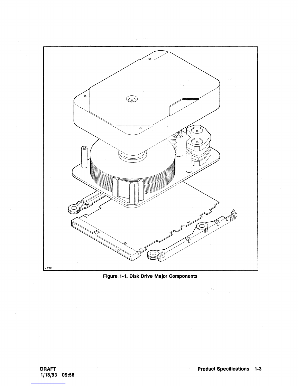
1-1. Disk Drive Major Components 1-3
Single-Unit Packaging . . . . 2-3
2-1.
2-2. Ten-Unit Packaging . . . . . 2-4
3-1. Disk Drive Addressing Structure
3-2. Formatted Physical Sector Allocation 3-14
3-3. Disk Drive Block Diagram . . . . . 3-15
E-1. Narrow, Single-Ended: Disk Drive Dimensions and Mounting Locations
E-2. Narrow, Single-Ended: Interface, Address and Option Connectors E-2
..
E-3. Narrow, Single-Ended: Connector Dimensions
E-4. Narrow, Single-Ended: Temperature Measuring
. . E-5
Points.
. . . . E-6
Tables
3-10
E-l
1-1. HP C2486A/88A/90A SCSI Disk Drive Capacities
1-2.
HP
C2486A/88A/90A Operating Specifications . .
1-3. HP
1-4.
2-1. Address/Configuration
2-2. Address/Configuration
2-3. Recommended Mating Connectors
3-1.
4-1. HP C2486A/88A/90A Supported SCSI Commands
A-I. Supported SCSI-2 Commands
B-1. Vendor Unique Commands
C-1. Vendor Unique
D-1. Reference Appendix Contents
E-l.
E-2. Narrow, Single-Ended: On-Board Terminator Power (TermPwr)
E-3. Narrow, Single-Ended: SCSI Connector Pin Assignments
C2486A/88A/90A DC Power Characteristics .
HP
C2486A/88A/90A Environmental Requirements
Pin-Set Information Locations
Option Descriptions
......
C2486A/88A/90A Cylinder
DERROR
Narrow, Single-Ended: Address and Option Connector Configurations
Allocation.
...
.....
Status
Codes
....
. . .
.
.
.
..
.....
Sources
1-4
1-6
1-9
1-10
2-6
2-7
2-9
3-11
4-4
A-3
B-1
C-l
D-l
E-3
E-4
.
E-5
DRAFT
1/18/93 09:58
Contents-5
Page 10

Page 11
Product Specifications
Product Description
The
HP
C2486A/88A/90A single-ended and differential disk drives are reliable, low cost,
high capacity, high performance, random access mass storage devices. Each
The
sputtered thin-film 3.5-inch (95 mm) disks as storage media.
is compatible with
1-1
shows
the
the
major
industry
components of
standard
Small Computer System Interface (SCSI-2). Figure
the
disk drive.
disk drive electrical interface
product
1
utilizes
These drives incorporate an advanced Digital
provides
alignment of an embedded servo system. High capacity and fast average transfer rates are
achieved with Multiple Zone Recording.
The
Capacities
Operating Specifications
DC Power Characteristics
Environmental Requirements
the
flexibility and performance of a dedicated servo system
product specifications are listed in
............................................
.........................................................
........................................................
....................................................
Signal Processor
the
following tables:
(DSP)
.-
..........................
hybrid servo design
and
the
dynamic head
Table
Table 1-2
Table 1-3
Table 1-4
Key Features
• High reliability (500,000 hours
• Synchronous
• Digital Signal Processor (DSP) hybrid servo sytem.
• High performance HP-designed balanced
•
Industry
• Fast and Wide Embedded SCSI-2 controller.
• Powerful HP-designed Reed-Solomon ECC.
data
standard
transfer
3.5-inch form factor and voltage requirements.
rate
MTBF).
of up
to
20
megabytes per second.
actuator.
that
1-1
DRAFT
1/18/93
09:58
Product Specifications 1·1
Page 12
Interface Options
The
following interface options are available:
Interface
001
002
012
Option
Description
SCSI-2 Fast, Narrow, Single-Ended
SCSI-2
Fast, Narrow, Differential
SCSI-2 Fast, Wide, Differential
Reference
Appendix
E
F
'.
G
Specials
For customer needs
can provide specially modified products. These modifications are ordered, defined, engineered,
and
manufactured under "special" contract negotiations.
that
differ from
the
products described in this manual, Hewlett-Packard
Related Documentation
The
following documentation provides information related
C2486A/88A/90A disk drives:
• Small Computer Systems Interface:
II
Common Command Set (CCS)
ANSI
XT39.2/86-109 (Rev 10h), XT39/89-042
of
the Small Computer System Interface (SCSI):
XT39.2/85-52 (Rev 4B)
to
the
operation of
the
HP
ANSI
1-2 ProductSpecifications
DRAFT
1/18/93 09:58
Page 13
w3101
Figure 1·1. Disk Drive Major Components
DRAFT Product Specifications
1/18/93 09:58
1·3
Page 14
Disk
Drive
Capacities
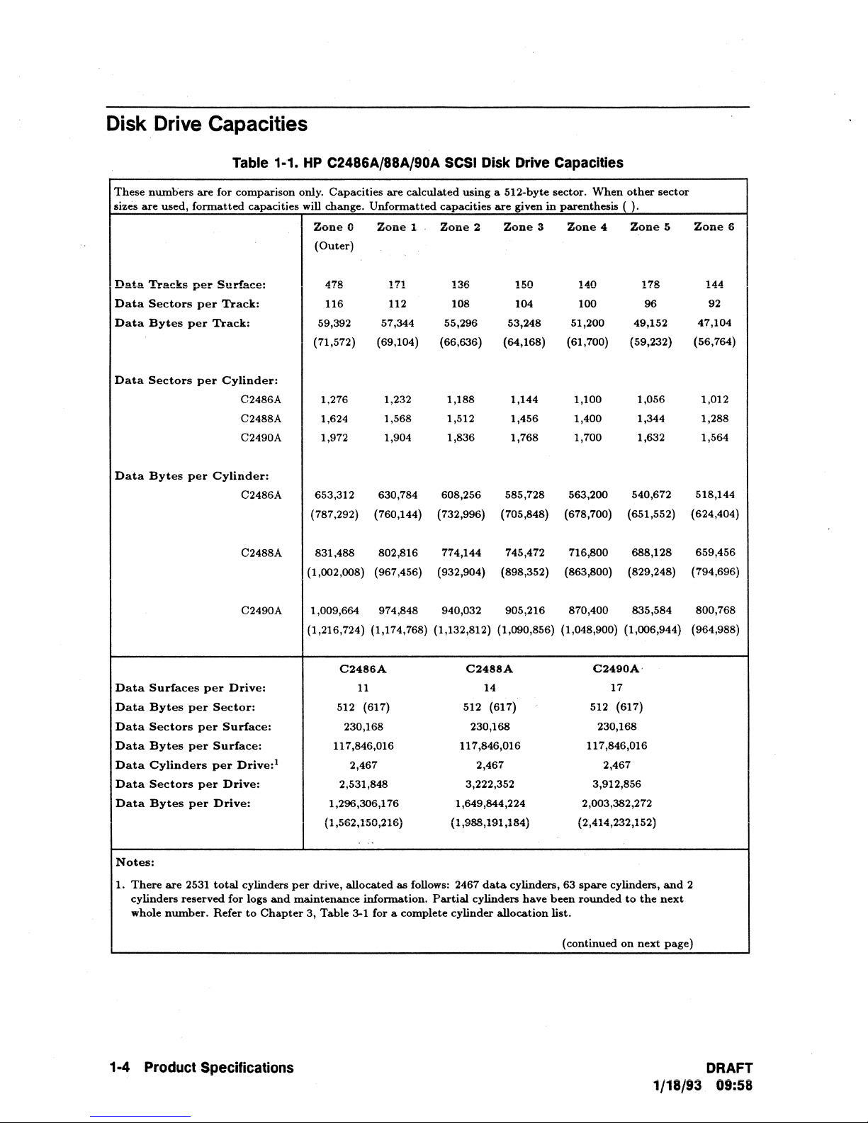
Table 1·1.
HP
C2486A/88A/90A SCSI Disk Drive Capacities
These
nuniliers
are
for
comparison
only. Capacities
are
calculated
using
a 512-byte sector.
When
other
sector
sizes
are
used,
formatted
capacities will change.
Unformatted
capacities
are
given
in
parenthesis ( ).
Zone
0
Zone
1 .
Zone
2
Zone
3
Zone
4
Zone
5
Zone
6
(Outer)
Data
Tracks
per
Surface:
478 171 136 150 140 178
144
Data
Sectors
per
Track:
116 112 108
104
100
96
92
Data
Bytes
per
Track:
59,392
57,344
55,296 53,248
51,200 49,152
47,104
(71,572) (69,104) (66,636) (64,168)
(61,700) (59,232)
(56,764)
Data
Sectors
per
Cylinder:
C2486A 1,276 1,232 1,188 1,144 1,100
1,056 1,012
C2488A
1,624
1,568 1,512 1,456
1,400 1,344 1,288
C2490A
1,972 1,904 1,836 1,768 1,700 1,632 1,564
Data
Bytes
per
Cylinder:
C2486A 653,312 630,784 608,256 585,728 563,200
540,672
518,144
(787,292)
(760,144) (732,996)
(705,848) (678,700) (651,552)
(624,404)
C2488A
831,488
802,816 774,144 745,472
716,800
688,128
659,456
(1,002,008) (967,456) (932,904) (898,352)
(863,800)
(829,248) (794,696)
C2490A 1,009,664
974,848 940,032 905,216 870,400 835,584
800,768
(1,216,724) (1,174,768) (1,132,812) (1,090,856) (1,048,900) (1,006,944)
(964,988)
C2486A
C2488A
C2490A'
Data
Surfaces
per
Drive:
11
14 17
Data
Bytes
per
Sector:
512 (617) 512 (617)
512 (617)
Data
Sectors
per
Surface:
230,168 230,168 230,168
Data
Bytes
per
Surface:
117,846,016 117,846,016 117,846,016
Data
Cylinders
per
Drive:
1
2,467 2,467 2,467
Data
Sectors
per
Drive:
2,531,848 3,222,352
3,912,856
Data
Bytes
per
Drive:
1,296,306,176
1,649,844,224
2,003,382,272
(1,562,150,216)
(1,988,191,184) (2,414,232,152)
...
Notes:
1.
There
are
2531
total
cylinders
per
drive,
allocated
as
follows: 2467
data
cylinders, 63
spare
cylinders,
and
2
cylinders
reserved
for
logs
and
maintenance
infonnation.
Partial
cylinders
have
been
rounded
to
the
next
whole
number.
Refer
to
Chapter
3,
Table
3-1 for a complete cylinder
allocation
list.
(continued
on
next
page)
1·4
Product SpecHications
DRAFT
1/18/93 09:58
Page 15
These
sizes
Data
Data
Data
Data
Data
numbers
are
used,
Tracks
Sectors
Bytes
Sectors
Bytes
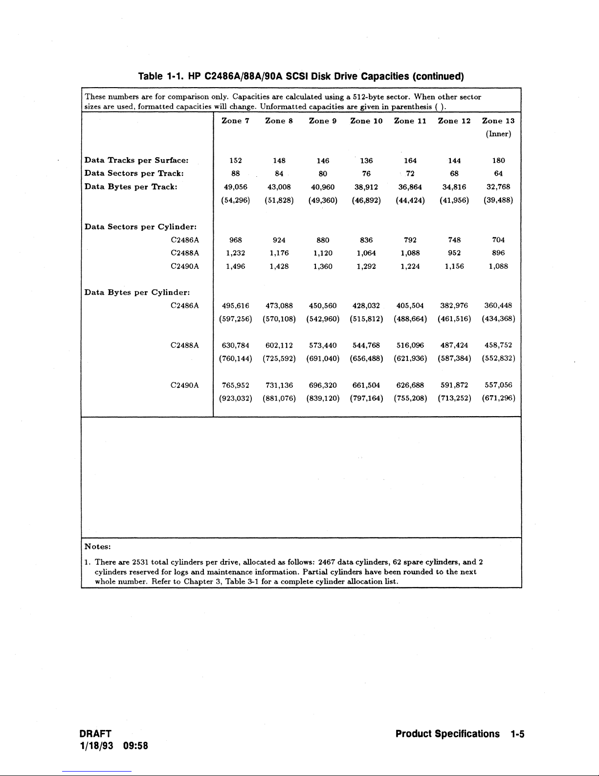
Table 1-1.
are
for
comparison
formatted
per
Surface:
per
Track:
per
Track:
per
Cylinder:
C2486A 968 924
C2488A
C2490A 1,496 1,428 1,360 1,292 1,224
per
Cylinder:
C2486A 495,616 473,088 450,560 428,032 405,504
HP
C2486A/88A/90A
only.
capacities
will change.
(597,256) (570,108)
SCSI
Capacities
Zone
152
88
49,056 43,008
(54,296) (51,828)
1,232
Unformatted
7
Zone
are
148
84
1,176
calculated
Disk Drive Capacities (continued)
using a 512-byte
capacities
8
Zone
146
40,960
(49,360) (46,892) (44,424) (41,956)
880 836
1,120 1,064 1,088 952
(542,960)
are
Zone
9
80 76
38,912 36,864
(515,812) (488,664) (461,516)
given in
10
136
sector.
When
parenthesis ( ).
Zone
11
164
72
792
other
sector
12
Zone
(hIDer)
180
64
32,768
(39,488)
704
896
1,088
(434,368)
Zone
144
68
34,816
748
1,156
382,976 360,448
13
Notes:
1.
There
cylinders
whole
are
2531
reserved
number.
C2488A 630,784 602,112 573,440
(760,144) (725,592) (691,040) (656,488)
765,952
(923,032) (881,076) (839,120)
per
drive,
maintenance
3,
Table
731,136
allocated
information.
3-1 for a
as
follows: 2467
complete
total
for
Refer
C2490A
cylinders
logs
and
to
Chapter
544,768 516,096 487,424 458,752
696,320 661,504
(797,164) (755,208)
dMa
Partial
cylinder
cylinders,
cylinders
allocation
(621,936) (587,384) (552,832)
626,688 591,872
(713,252) (671,296)
62
spare
have
been
list.
cylinders,
rounded
to
the
and
next
557,056
2
DRAFT
1/18/93 09:58
Product Specifications 1-5
Page 16
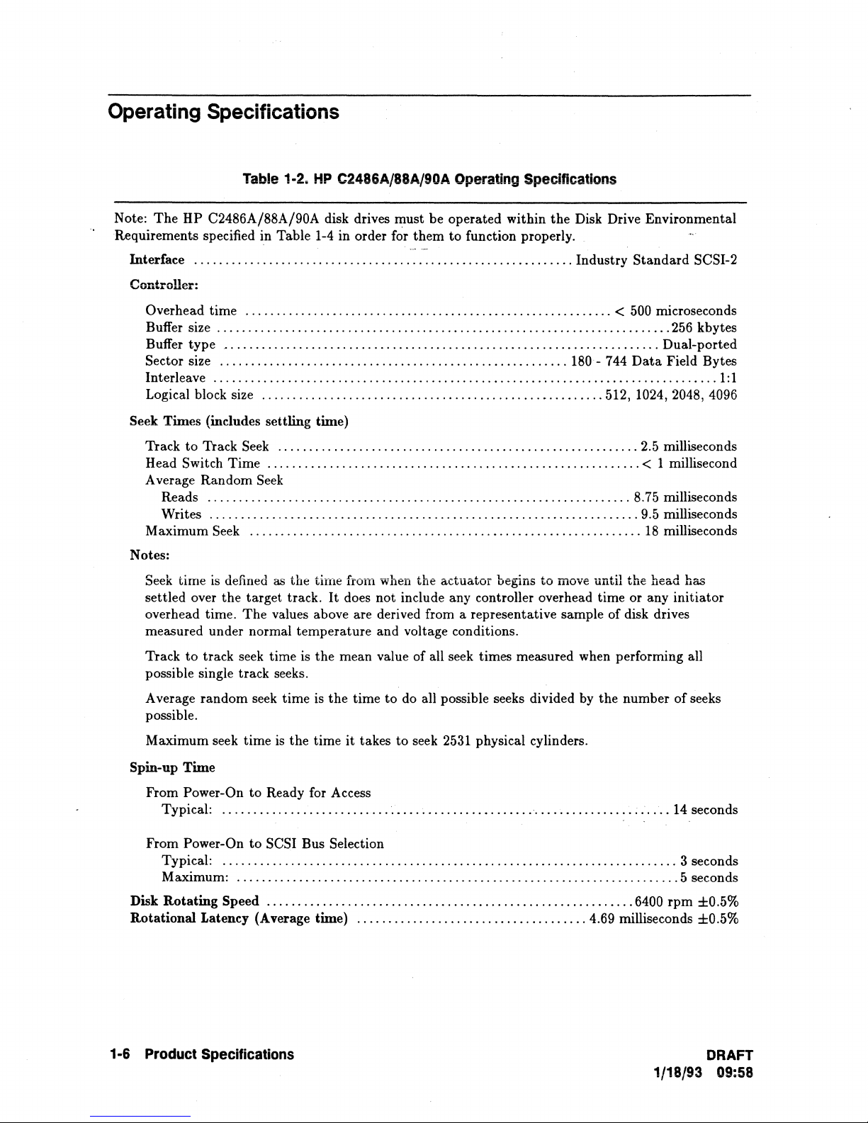
Operating Specifications
Table 1·2.
Note:
The
HP C2486A/88A/90A disk drives must be operated within
Requirements specified in Table 1-4 in order for them to function properly.
Interface
Controller:
Overhead
Buffer size
Buffer type
Sector size
Interleave
Logical block size
Seek Times
Track
Head Switch Time
A verage Random
Maximum Seek
Notes:
Seek time
settled over the target track.
overhead time.
measured under normal temperature and voltage conditions.
.............................................................
time
...........................................................
.........................................................................
......................................................................
........................................................
.................................................................................
.......................................................
(includes settling time)
to
Track Seek
............................................................
Seek
Reads
Writes
....................................................................
.....................................................................
...............................................................
is
defined
The
HP
C2486A/88A/90A Operating Specifications
the
..........................................................
as
the titne from when the actuator begins to move until the head has
It
does not include any controller overhead time or any initiator
values above are derived from a representative sample of disk drives
Disk Drive Environmental
Industry
Standard
SCSI-2
< 500 microseconds
256
kbytes
Dual-ported
180
- 744
Data
Field Bytes
1:
512, 1024,2048, 4096
2.5 milliseconds
< 1 millisecond
8.75 milliseconds
9.5 milliseconds
18
milliseconds
1
Track
to
track seek time is the mean value of all seek times measured when performing all
possible single track seeks.
A verage random seek time is the time to
possible.
Maximum seek time
Spin-up Time
From
Power-On to Ready for Access
Typical:
From
Typical:
Maximum:
Disk Rotating
Rotational Latency (Average time)
........................................................................
Power-On
.........................................................................
Speed
is
the time
to
SCSI Bus Selection
.......................................................................
...................
1·6 Product Specifications
do
all possible seeks divided
it
takes
to
seek 2531 physical cylinders.
,
.......................................
.....................................
by
the number
4.69 milliseconds ±O.5%
6400
of
seeks
14 seconds
3 seconds
5 seconds
rpm
±0.5%
DRAFT
1/18/93 09:58
Page 17
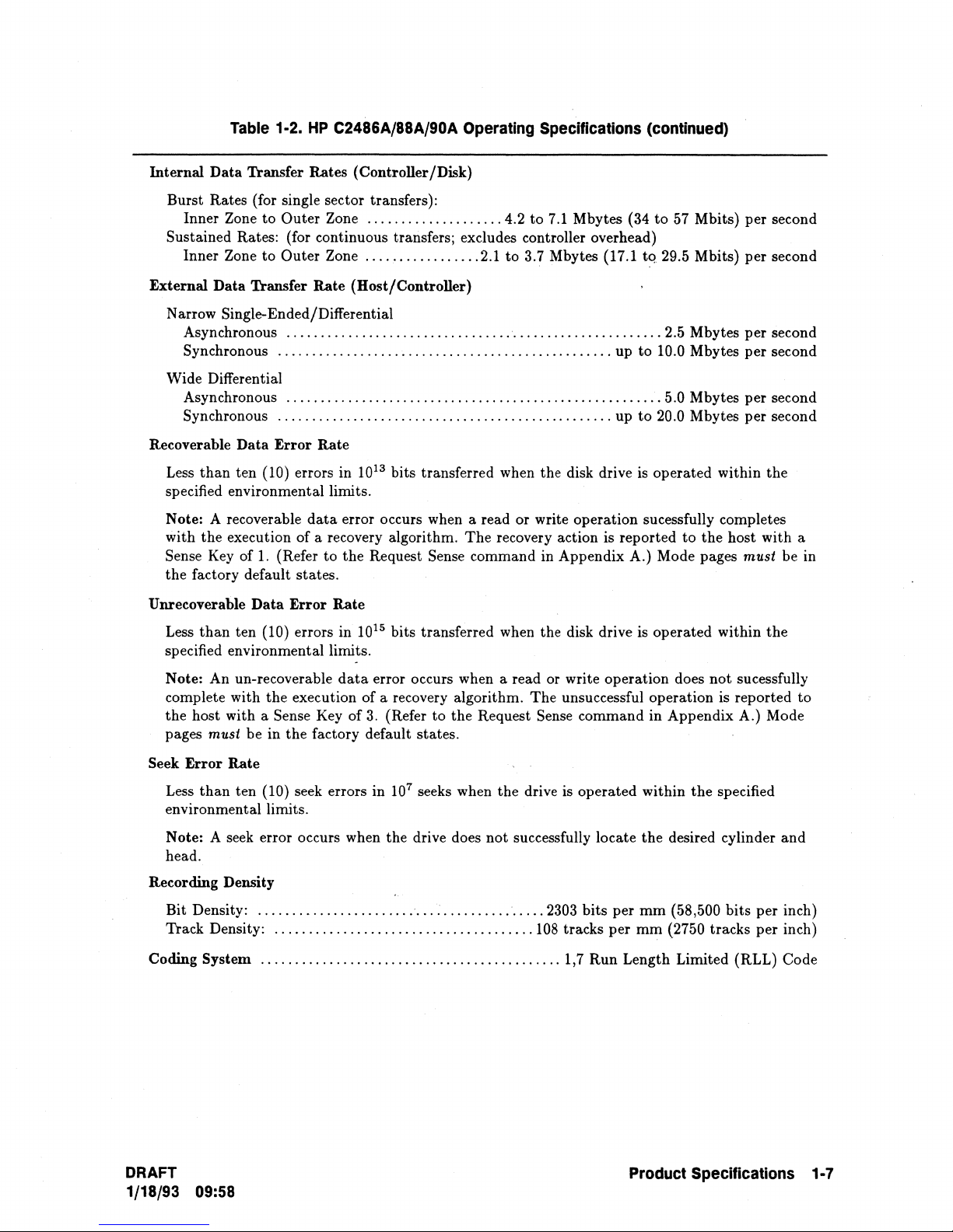
Table 1·2.
HP
C2486A/88A/90A Operating Specifications (continued)
Internal Data Transfer Rates (Controller/Disk)
Burst Rates (for single sector transfers):
Inner Zone to
Outer Zone
....................
4.2 to
7.1
Mbytes (34
Sustained Rates: (for continuous transfers; excludes controller overhead)
Inner Zone to
Outer Zone
.................
2.1
to 3.7 Mbytes (17.1
External Data Transfer Rate (Host/Controller)
to
57
Mbits) per second
tq
29.5 Mbits) per second
N arrow
Single-Ended/Differential
Asynchronous
Synchronous
.......................................................
.................................................
2.5 Mbytes per second
up to 10.0 Mbytes per second
Wide Differential
Asynchronous
Synchronous
.......................................................
.................................................
up
5.0 Mbytes per second
to
20.0 Mbytes per second
Recoverable Data Error Rate
Less
than
ten (10) errors in
13
10
bits transferred when the disk drive
is
operated within the
specified environmental limits.
data
Note: A recoverable
with the execution of a recovery algorithm. The recovery action is reported
Sense
Key
of
1.
(Refer to the Request Sense command in Appendix A.) Mode pages must be in
error occurs when a read or write operation sucessfully completes
to
the host with a
the factory default states.
Unrecoverable Data Error Rate
Less
than
ten (10) errors in
15
10
bits transferred when the disk drive is operated within the
specified environmental limits.
data
Note: An un-recoverable
error occurs when a read or write operation does not sucessfully
complete with the execution of a recovery algorithm. The unsuccessful operation is reported to
Sense
Key
of
3.
the host with a
must be in the factory default states.
pages
(Refer to the Request Sense command in Appendix A.) Mode
Seek Error Rate
Less
than ten (10) seek errors in
environmental limits.
seek
Note: A
error occurs when the drive does not successfully locate the desired cylinder and
head.
Recording Density
Bit Density:
Track Density:
Coding System
DRAFT
..........................
......................................
............................................
1/18/93 09:58
107 seeks when the drive
:
...............
2303
108
is
operated within the specified
bits per
mm
(58,500 bits per inch)
tracks per mm (2750 tracks per inch)
1,7 Run Length Limited (RLL) Code
Product Specifications 1·7
Page 18
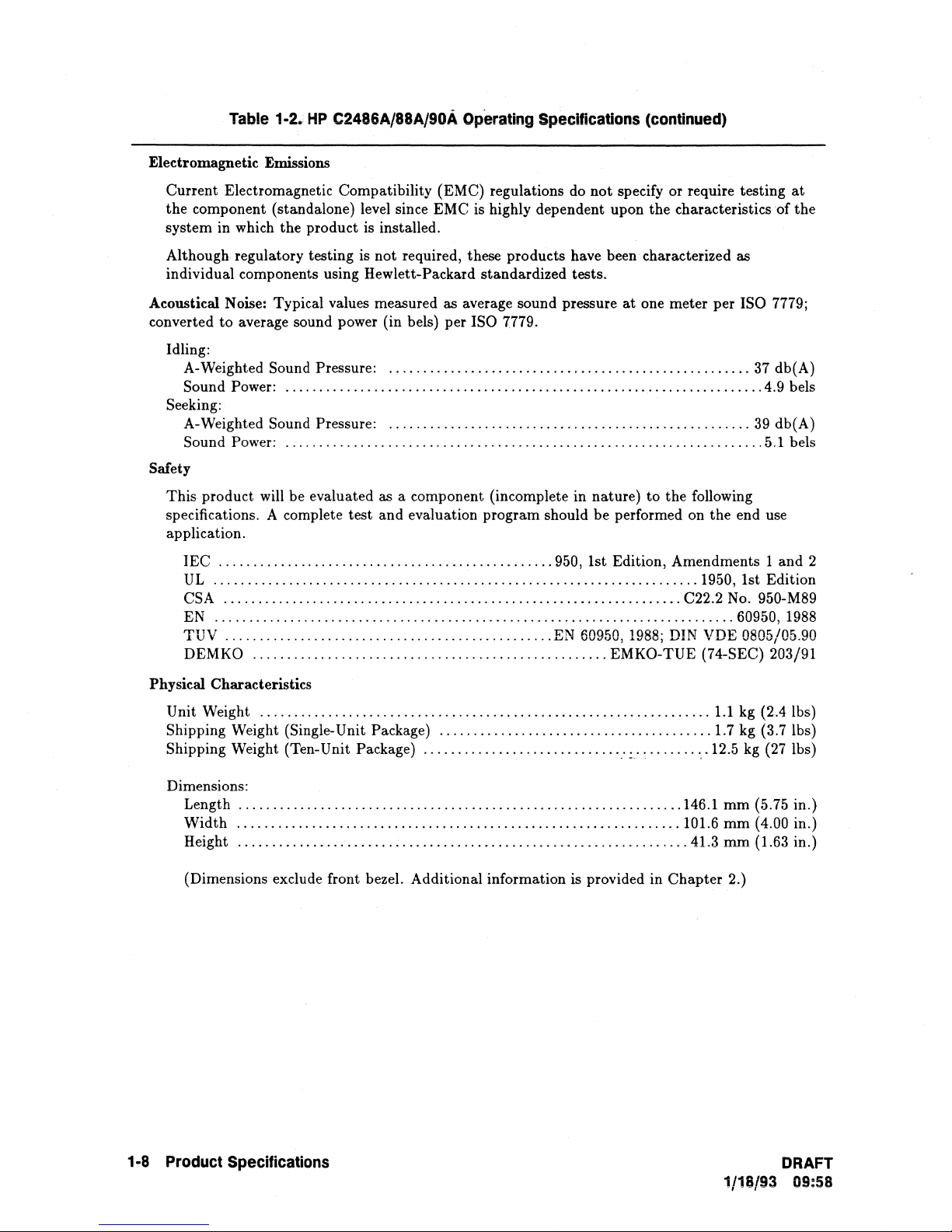
Table
Electromagnetic Emissions
1·2.;
HP
C2486A/88A/90A
Operating
Specifications
(continued)
Current Electromagnetic Compatibility
the component (standalone) level since EMC is highly dependent upon the characteristics of the
system in which the product is installed.
Although regulatory testing is not required, these products have been characterized as
individual components using Hewlett-Packard standardized tests.
Acoustical Noise: Typical values measured as average sound pressure
converted to average sound power (in bels) per
Idling:
A-Weighted
Sound Power:
Seeking:
A-Weighted
Sound Power:
Safety
This product will be evaluated as a component (incomplete in nature) to the following
specifications. A complete test and evaluation program should be performed on the end use
application.
lEe
.................................................
UL
.......................................................................
CSA
EN
............................................................................
TUV
DEMKO
Sound Pressure:
......................................................................
Sound Pressure:
......................................................................
...................................................................
................................................
....................................................
.....................................................
.....................................................
(EMC) regulations
ISO 7779.
do
not specify or require testing
at
one meter per ISO 7779;
950,
1st Edition, Amendments 1 and 2
1950, 1st Edition
C22.2
No.
60950,
EN
60950,
1988;
DIN
VDE 0805/05.90
EMKO-TUE (74-SEC) 203/91
37
4.9 bels
39
5.1 bels
950-M89
at
db(A)
db(A)
1988
Physical Characteristics
Unit Weight
Shipping Weight (Single-Unit Package)
Shipping Weight (Ten-Unit Package)
Dimensions:
Length
Width
Height
(Dimensions exclude front bezel. Additional information is provided in Chapter 2.)
..................................................................
........................................
.............................
.................................................................
.................................................................
..................................................................
".:.:
..........
1.1
kg (2.4 Ibs)
1.7 kg (3.7Ibs)
12.5
kg
(27 Ibs)
146.1 mm (5.75 in.)
101.6 rom (4.00 in.)
41.3 rom (1.63 in.)
1·8
Product
Specifications
DRAFT
1/18/93 09:58
Page 19
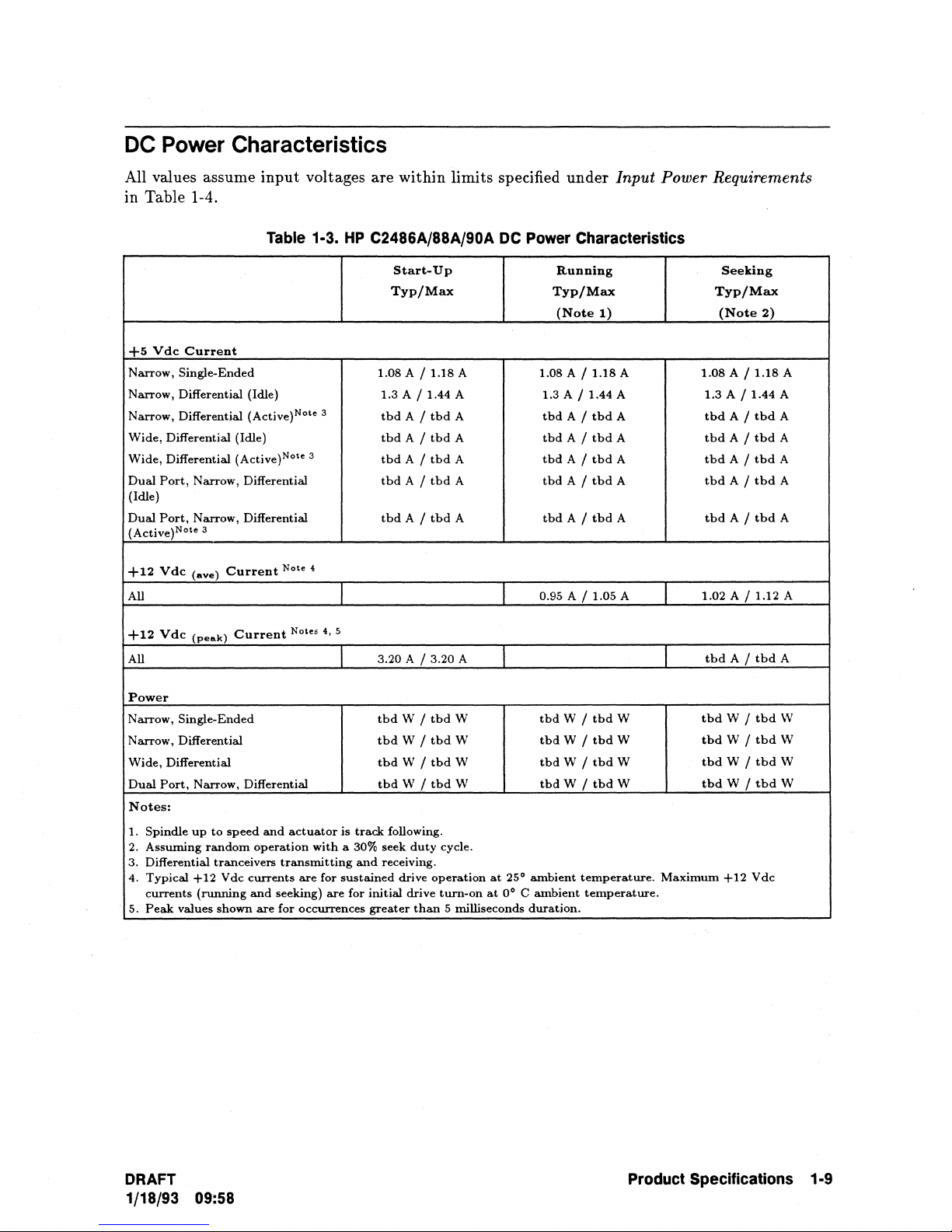
DC
Power
Characteristics
All values assume
in Table 1-4.
+5 V dc
Narrow,
Narrow,
Narrow,
Wide,
Wide,
Dual
(Idle)
Dual
(Active)Note 3
+12
All
Current
Single-Ended
Differential (Idle)
Differential (Active)Note 3
Differential (Idle)
Differential (Active)Note 3
Port,
Port,
Vdc
Narrow,
Narrow,
(ave)
Differential
Differential
Current
input
voltages
Table 1·3.
Note
4
are
within
HP
C2486A/88A/90A
Start-Up
Typ/Max Typ/Max
1.08
1.3
A /
tbd
tbd
tbd
tbd
tbd
limits specified
A /
1.18
A
1.44
A
A /
tbd
A
A /
tbd
A
A /
tbd
A
A /
tbd
A
A /
tbd
A
DC
under
Input Power Requirements
Power Characteristics
Running
(Note
1)
1.08
A /
1.18
A
1.3
A /
1.44
A
tbd
A /
tbd
A
tbd
A /
tbd
A
tbd
A /
tbd
A
tbd
A /
tbd
A
tbd
A /
tbd
A
0.95
A /
1.05
A
Seeking
Typ/Max
(Note
1.08
A /
1.3
A /
tbd
tbd
A /
tbd
tbd
tbd
1.02
A /
A /
A /
A /
A /
2)
1.18
1.44
tbd
tbd
tbd
tbd
tbd
1.12
A
A
A
A
A
A
A
A
+12
Vdc
All
Power
Narrow,
Narrow,
Wide,
Differential
Dual
Port,
Notes:
1.
Spindle
2.
Assuming
3.
Differential
4.
Typical
currents
5.
Peak
(peak)
Current
Single-Ended
Differential
Narrow,
up
+12
(running
values
Differential
to
speed
random
tranceivers
Vdc
shown
and
operation
transmitting
currents
and
seeking)
are
for
Notes
4, 5
actuator
with
are
for
are
occurrences
3.20
tbd
tbd
tbd
tbd
is
track
a
30%
seek
and
receiving.
sustained
for
initial
greater
A /
3.20
W /
tbd
W /
tbd
W /
tbd
W /
tbd
following.
duty
drive
drive
than
A
W
W
W
W
cycle.
operation
turn-on
at
5 milliseconds
at
25°
0°
tbd
tbd
tbd
tbd
ambient
C
ambient
duration.
W /
tbd
W /
tbd
W /
tbd
W /
tbd
temperature.
temperature.
W
W
W
W
tbd
tbd
tbd
tbd
tbd
Maximum
A /
W /
W /
W /
W /
+12
tbd
tbd
tbd
tbd
tbd
Vdc
A
W
W
W
W
DRAFT
1/18/93
09:58
Product Specifications 1·9
Page 20
Environmental
R~quirements
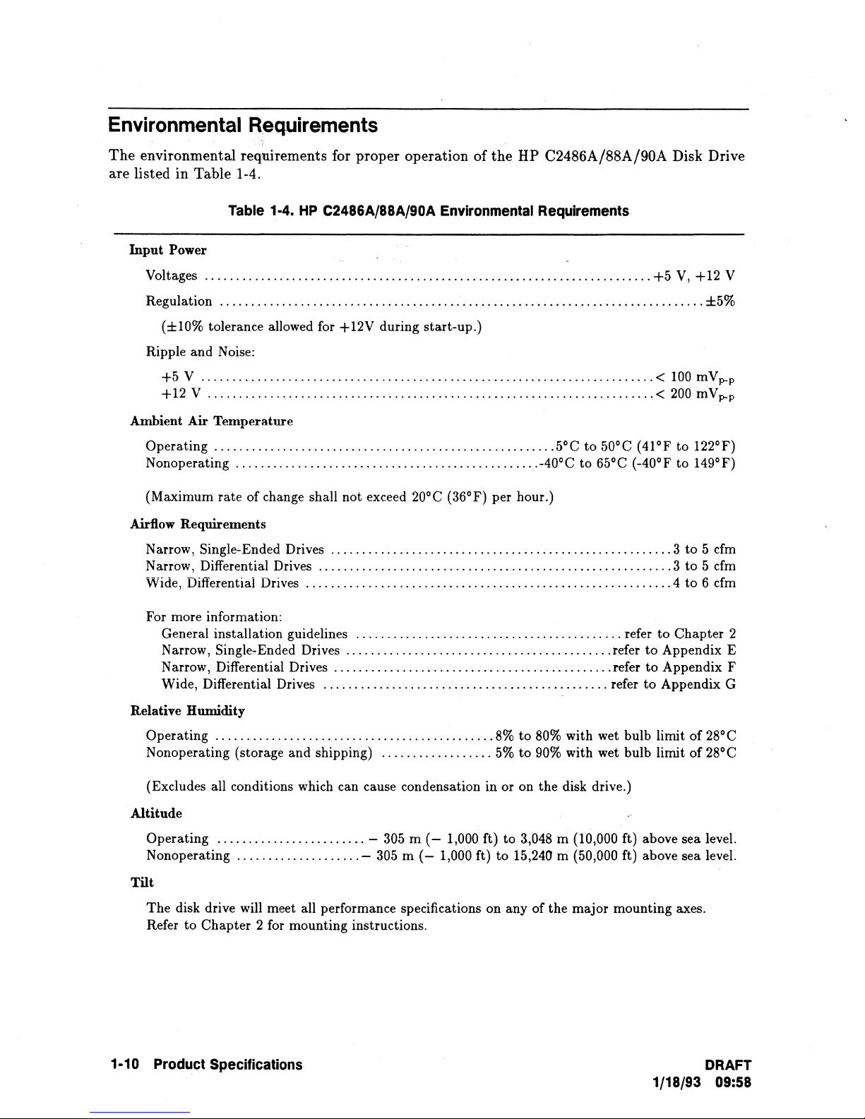
The environmental requirements for proper operation of the HP C2486A/88A/90A Disk Drive
are listed in Table 1-4.
Table 1-4.
Input Power
Voltages
Regulation
(±10% tolerance allowed for +12V during start-up.)
Ripple and Noise:
+5 V .........................................................................
+12 V
Ambient
Operating
Nonoperating
(Maximum rate of change shall not exceed 20°C (36°F) per hour.)
Airflow Requirements
Narrow, Single-Ended Drives
Narrow, Differential Drives
Wide, Differential Drives
For more information:
General installation guidelines
Narrow, Single-Ended Drives
Narrow, Differential Drives
Wide, Differential Drives
........................................................................
..............................................................................
........................................................................
Air
Temperature
.......................................................
.................................................
HP
C2486A/88A/90A Environmental Requirements
.......................................................
.........................................................
...........................................................
...........................................
...........................................
.............................................
..............................................
+5
V,
+12 V
±5%
<
100
mVp-p
<
200
mVp-
5°C
to
50°C (41°F to 122°F)
-40°C to 65°C (-40°F to 149°F)
3 to 5
cfm
3 to 5 cfm
4 to 6 cfm
refer to Chapter 2
refer to Appendix E
refer to Appendix F
refer
to
Appendix G
p
Relative Humidity
Operating
Nonoperating (storage and shipping)
(Excludes all conditions which can cause condensation in or on the disk drive.)
Altitude
Operating
Nonoperating
Tilt
The disk drive will meet all performance specifications on any of the major mounting axes.
Refer to Chapter 2 for mounting instructions.
1·10 Product Specifications
.............................................
........................
....................
..................
-
305 m (-
-
305 m (-
8%
to
80%
with wet bulb limit of 28°C
5%
to
90%
with wet bulb limit
1,000 ft) to 3,048 m (10,000 ft) above sea level.
1,000 ft)
to
15,240
IIi
(50,000 ft) above sea level.
of
28°C
DRAFT
1/18/93 09:58
Page 21
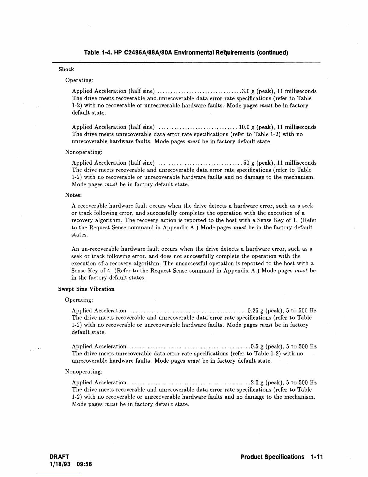
Table
Shock
Operating:
Applied Acceleration
The
drive meets recoverable
1-2)
with
default
state.
1·4.
HP
C2486A/88A/90A Environmental Requirements (continued)
(half
no recoverable
sine)
................................
and
unrecoverable
or
unrecoverable hardware faults. Mode pages must
data
error
3.0 g (peak),
rate
specifications (refer
11
milliseconds
to
be
in
factory
Table
Applied Acceleration
The
drive meets unrecoverable
(half
sine)
unrecoverable hardware faults. Mode pages
Nonoperating:
(half
Applied Acceleration
The
drive meets recoverable
1-2) with no recoverable
Mode pages
must
be
sine)
and
or
unrecoverable
in
factory default
Notes:
A recoverable
or
track
hardware
following error,
recovery algorithm.
to
the
Request Sense
fault
occurs when the drive detects a
and
successfully completes the
The
recovery action is
command
states.
to
the
states.
fault
and
Request Sense
An un-recoverable hardware
or
track
seek
execution
Sense Key
in
the
Swept Sine
factory default
following error,
of
a recovery algorithm.
of
4.
(Refer
Vibration
Operating:
..............................
data
error
rate
specifications (refer
must
be
in factory default
................................
unrecoverable
data
hardware
error
faults
rate
and
state.
operation
reported
to
the
in Appendix A.) Mode pages
occurs when
does
not
The
unsuccessful
the
drive
detects a hardware
successfully complete
operation
command
in
Appendix
10.0 g (peak),
to
Table
state.
50 g (peak),
specifications (refer
no
damage
hardware
host
with
must
is
the
reported
error, such
with
the
a Sense Key
be
in
operation
A.) Mode pages
11
milliseconds
1-2)
with
11
milliseconds
to
to
the
mechanism.
as
execution
of
the
factory default
error, such as a
with
to
the
host with a
no
Table
a seek
of
1.
the
must
a
(Refer
be
Applied Acceleration
The
drive meets recoverable
1-2) with no recoverable
default
state.
Applied Acceleration
The
drive meets unrecoverable
unrecoverable hardware faults. Mode pages
Nonoperating:
Applied Acceleration
The
drive meets recoverable
1-2) with no recoverable
Mode pages
must
be
DRAFT
1/18/93 09:58
............................................
and
unrecoverable
or
unrecoverable
data
hardware
..............................................
data
error
rate
specifications (refer
must
be
..............................................
and
unrecoverable
or
unrecoverable hardware faults
in factory default
state.
data
0.25 g
error
rate
specifications (refer
faults. Mode pages
0.5 g
to
Table
in
factory
default
2.0 g (peak), 5
error
rate
specifications (refer
and
no
damage
Product Specifications 1·11
(peak), 5 to
must
be
(peak), 5 to
1-2)
state.
to
the
500 Hz
to
Table
in
factory
500
with
no
to
500
to
Table
mechanism.
Hz
Hz
Page 22
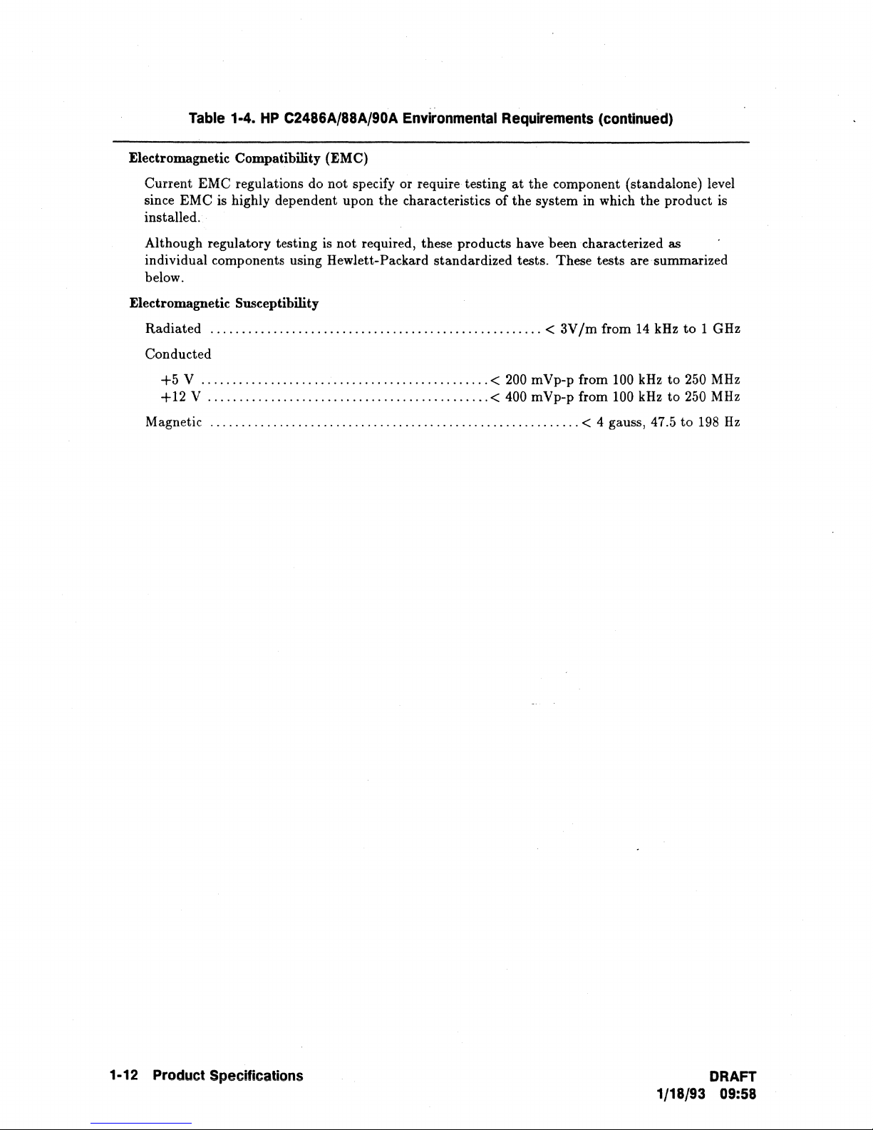
Table 1·4.
Electromagnetic Compatibility (EMC)
HP
C2486A/88A/90A Environmental Requirements (continued)
Current EMC regulations do not specify or require testing
since EMC is highly dependent upon the characteristics of the system in which
installed.
Although regulatory testing is not required, these products have been characterized
individual components using Hewlett-Packard standardized tests. These tests are summarized
below.
Electromagnetic Susceptibility
Radiated
Conducted
+5 V ..............................................
+12 V .............................................
Magnetic
.....................................................
...........................................................
at
the component (standalone) level
the
<
3V
1m
from
14
<
200
m Vp-p from
100
kHz to 250
< 400 mVp-p from 100 kHz
< 4 gauss, 47.5 to
product is
as
kHz
to
to
250
1 GHz
MHz
MHz
198
Hz
1·12 Product Specifications
DRAFT
1/18/93 09:58
Page 23
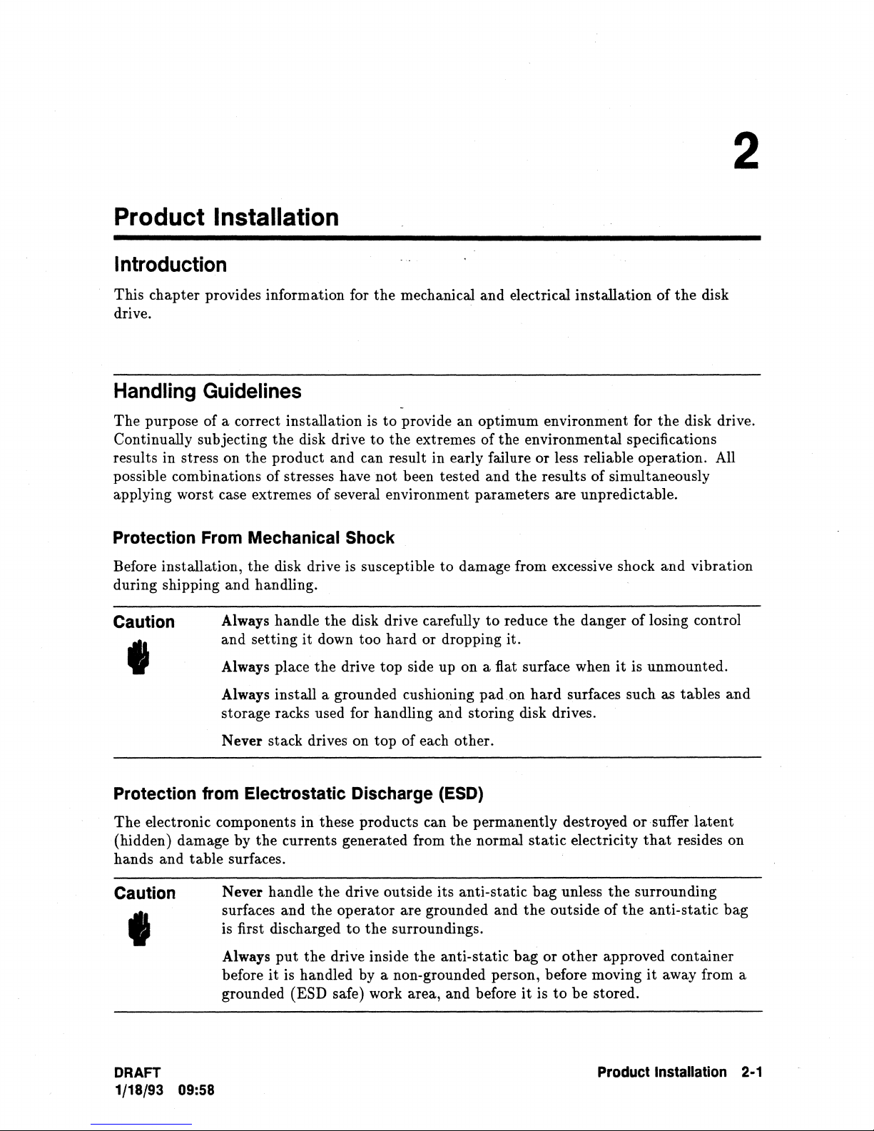
Product Installation
Introduction
2
This chapter provides information for
drive.
Handling
The purpose of a correct installation is
Continually subjecting
results in stress on
possible combinations of stresses have not been tested
applying worst case extremes of several environment parameters are unpredictable.
Protection From Mechanical Shock
Before installation,
during shipping
Caution
Guidelines
the
the
product and can result in early failure or less reliable operation. All
the
disk drive is susceptible to damage from excessive shock
and
handling.
Always handle
and setting
disk drive
the
it
down too
the
mechanical and electrical installation
to
provide
to
the
disk drive carefully
hard
an
extremes
or dropping it.
optimum environment for
of
the
environmental specifications
and
the
to
results
reduce
the
of
simultaneously
danger
of
of
the
and
losing control
,
Always place
Always install a grounded cushioning
storage racks used for handling and storing disk drives.
the
drive top side up on a fiat surface when
pad
on
hard
it
is unmounted.
surfaces such as tables
the
disk
disk drive.
vibration
and
Never stack drives on top of each other.
Protection from Electrostatic Discharge (ESD)
The
electronic components in these products can
(hidden) damage by
hands
Caution
and
table surfaces.
the
currents generated from
Never handle
surfaces and
is first discharged
I
Always
before
grounded
DRAFT
1/18/93 09:58
put
it
is handled by a non-grounded person, before moving
(ESD safe) work area, and before
be
permanently destroyed
the
normal
the
drive outside its anti-static bag unless
the
operator
to
the
drive inside
are grounded and
the
surroundings.
the
anti-static
static
the
bag
it
is
electricity
outside of
or
other
to
be stored.
or
. suffer
that
the
surrounding
the
anti-static
approved container
it
Product Installation 2·1
latent
resides on
bag
away from a
Page 24
Unpacking
the
Disk
Drive
Note
The disk drive is shipped in a reusable shipping container. Retain
container and all packing material for re-shipment.
Inspecting the Shipping Container
When your shipment arrives, ensure
lading. Inspect
during transit.
be
present when
the
shipping container immediately upon receipt for evidence of mishandling
IT
the
container is damaged or water stained, request
the
container is unpacked.
that
.-.
it
is complete as specified by
the
carrier's bill of
that
the
the
shipping
carrier's agent
Inspecting the Disk Drive
Remove the disk drive from the shipping container and inspect
that
may have occurred during shipment.
Hewlett-Packard and
file
a claim with any carrier involved.
If
any damage is observed, immediately notify
it
for any mechanical damage
Recording the Serial Number
Each drive carries an individual serial number. Keep a record of all serial numbers and dates
of purchase.
recovery, as well as for any insurance claims.
IT
your drive is lost or stolen, this information is often necessary for tracing and
Disk
Drive
Returns
Return Shipment Addresses
Vendor
Return the drive(s)
ordering information for
Hewlett-Packard Direct
Purchases
to
the vendor from which
that
address.
Purchases
it
was purchased. Refer
to
your original
H you purchased your drive(s) directly from Hewlett-Packard, contact your Hewlett-Packard
sales representative for instructions.
..
2-2
Product
Installation
DRAFT
1/18/93 09:58
Page 25
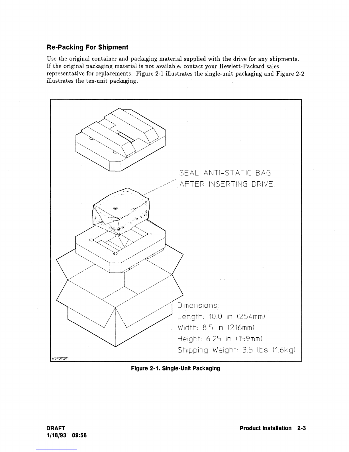
Re-Packing
For
Shipment
Use the original container and packaging material supplied with
If
the original packaging material is not available, contact your Hewlett-Packard sales
representative for replacements. Figure
the
illustrates
ten-unit packaging.
2-1
illustrates
the
single-unit packaging and Figure 2-2
SEAL ANTI-STATIC
AFTER INSERTING
the
drive for any shipments.
BAG
DRIVE.
WSPDH201
DRAFT
1/18/93 09:58
Figure
2-1.
Single-Unit
Length:
Width: 8 5 in
Height: 6.25 in
10.0 in (254mm)
(216mm)
(159mm)
Shipping Weight: 3.5
Packaging
Product
lbs
(1.6kg)
Installation
2-3
Page 26
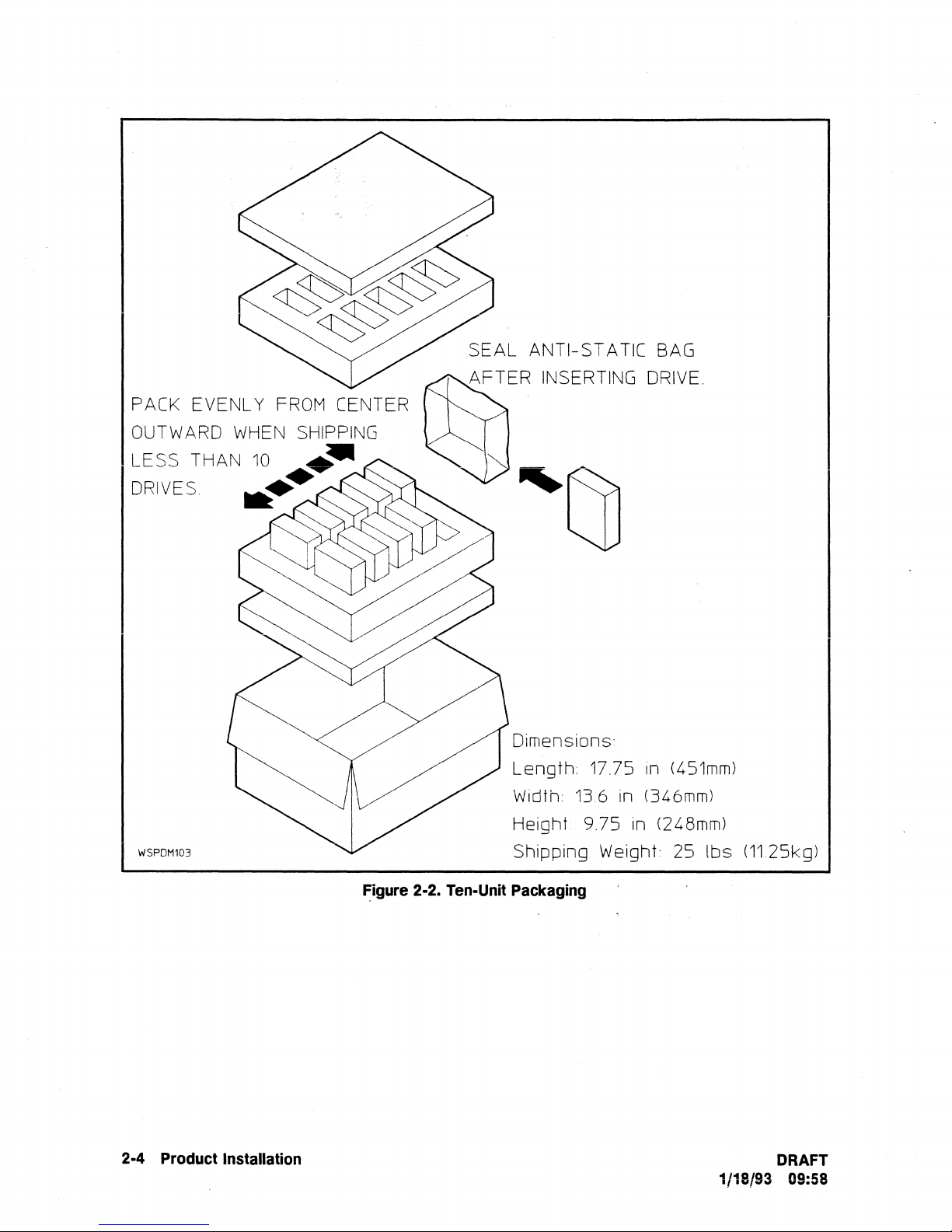
SEAL ANTI-STATIC
BAG
PACK EVENLY
OUTWARD
LESS THAN
DRIVES
WHEN
10
..
WSPDM103
FROM
SHIPPING
••
CENTER
.-.A
Dimensions:
Length:
Width:
Height 9.75 in (248mm)
Shipping Weight: 25
17.75
136
in
(451mm)
in (346mm)
lbs
(1125kg)
2-4
Product
Installation
~igure
2-2.
Ten-Unit
Packaging
DRAFT
1/18/93 09:58
Page 27

Mounting
Information
The disk drive can be mounted in any of
Safety /Regulatory
• When installing an HP C2486A/88A/90A Disk Drive into
regulatory Conditions of Acceptability must be considered. Contact your sales/service
representative for a-copy of
•
If
the
front bezel option has been installed,
application.
•
If
installing an HP C2486A/88A/90A Disk Drive with an
complete installation should be evaluated in
Chassis
The
the
only and do not include clearances for power and interface connectors.
Physical
There are twelve (12) threaded mounting holes (for no. 6-32 screws) on
each side, and four on the
respective appendices for each option.
Dimensions
physical dimensions and mounting screw locations for each interface option are shown in
respective appendices for each option.
Mounting
Compliance
the
Hewlett-Packard Conditions
and
Mounting
bottom
(see Figure 2-3).
the
major
Screw
The
mounting axes.
an
end
of
Acceptability.
it
should be evaluated in
adaptor
the
intended end use application.
Locations
length dimensions shown are for
Use
the mounting guidelines listed in
use
product, safety
the
intended end use
mounting frame,
the
the
disk
drive: four on
and
the
chassis
the
Airflow
The
drive is maintained within
1.
Airflow
drive should be operated as cool as possible.
option are listed in Table 1-4.
function
The
measuring points on
respective appendix for each interface option.
All temperature measurements should be made under worst case operating conditions, These
conditions should be maintained for
before making any measurements.
Requirements
disk drive must be installed
is
required to maintain disk drive performance and reliability. For best results,
of
the
specific airflow
airflow
pattern
around
the
HDA and
so
that
the
ambient air temperature surrounding
the
limits specified under Environmental Requirements in
The
airflow requirements for each interface
The
majority of
pattern
the
drive should be adjusted to prevent
inside
the
PCA
at
least one hour
the
air should
the
cabinet where
from exceeding
to
allow
flow
across
the
the
maximum limits shown
the
drive
the
disk drive is installed.
the
temperature
to
the
disk
Chapter
the
PCA. This is a
in
the
reach equilibrium
DRAFT
1/18/93 09:58
Product Installation 2·5
Page 28
Front
The
the
Panel
light
emitting
operational
status
normal operation.
LED
Indicator
diode (LED) on
of
the
the
front of
the
disk drive is
drive from power-on, through
an
activity light
the
self-test diagnostics, and into
that
indicates
LOn
2.
Flashing
3.
Intermittent
Address
The
location
interface option
and
Configuration
and
set-up of
and
its
the
associated
contained in its own appendix
use .
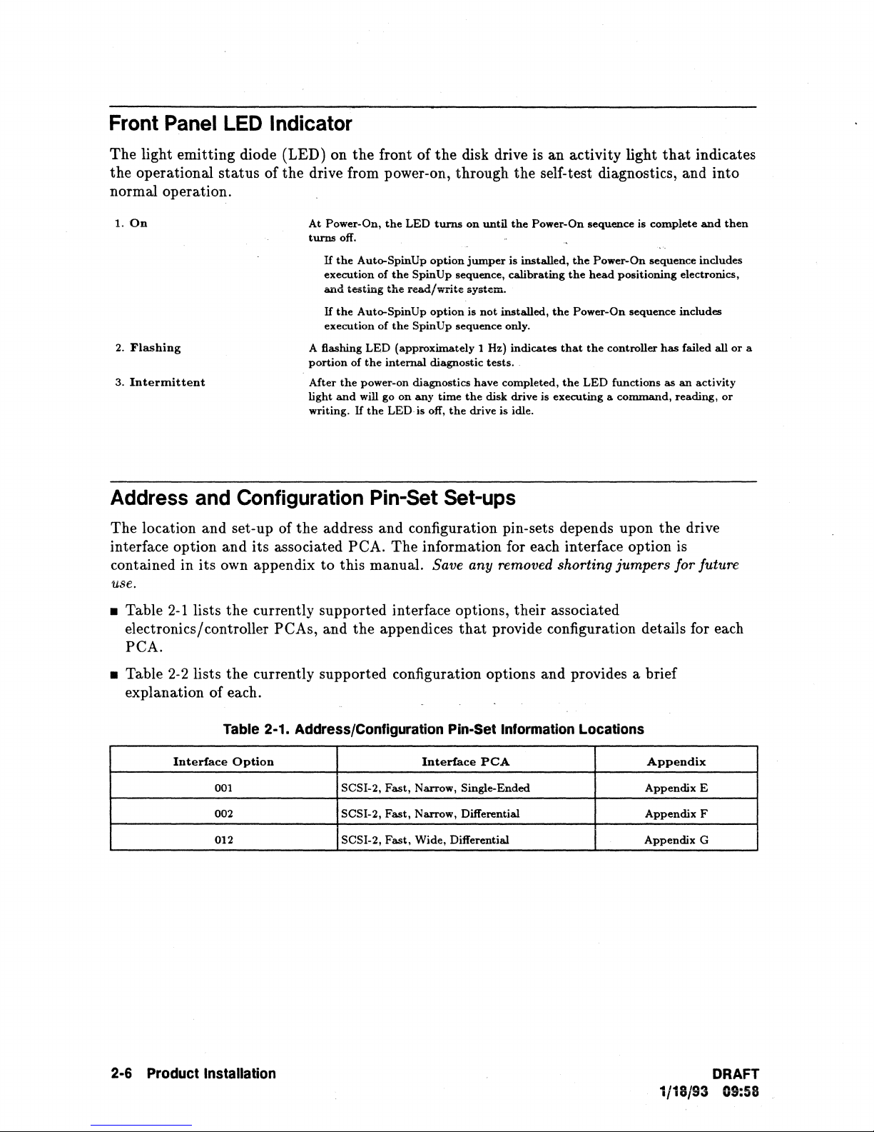
• Table
2-1
lists
the
currently supported interface options, their associated
electronics/controller
peA
.
peAs,
At
Power-On,
turns
off.
If
the
execution
and
If
the
execution
A flashing
portion
After
the
light
and
writing.
address
to
this manual. Save any removed shorting jumpers for future
and
the
LED
turns
Auto-SpinUp
of
testing
Auto-SpinUp
of
LED
of
the
internal
power-on diagnostics
will go
If
the
option
the
SpinUp
the
read/write
option
the
SpinUp
(approximately
diagnostic
on
any
LED
is off,
Pin-Set
and
configuration pin-sets depends upon
peA.
the
appendices
The
information for each interface option is
on
until
jumper
sequence,
system.
is
not
sequence only.
1 Hz)
tests.
have
time
the
disk
the
drive is idle.
Set-ups
that
provide configuration details for each
the
Power-On
is
installed,
calibrating
installed,
indicates
completed,
drive
is
sequence
the
Power-On
the
head
the
Power-On
that
the
the
LED
executing a command,
is
sequence
positioning
sequence
controller
functions
complete
has
the
as
and
includes
electronics,
includes
failed
all
an
activity
reading,
drive
then
or
or
a
• Table 2-2 lists
explanation of each.
Table
Interface
001 SCSI-2,
002
012 SCSI-2,
2-6
Product
Installation
the
currently supported configuration options
2-1.
Option
AddressiConfiguration
Fast,
SCSI-2,
Fast,
Fast,
Pin-Set
Interface
Narrow, Single-Ended
Narrow, Differential
Wide,
Differential
Information
peA
and
provides a brief
Locations
Appendix
Appendix
Appendix
Appendix
E
F
G
DRAFT
1/18/93 09:58
Page 29

Table
2·2.
Address/Configuration
Option
Descriptions
Configuration
Auto
Spin
Up
Parity
SCSI-l/SCSI-2
SCSI Address Selection Narrow SCSI drives
Synchronized
Option
Spindle.
When
shorted,
not
will
spin
up
SENSE, INQUIRY, RESERVE, RELEASE,
access.
When
shorted,
drive does
shorted.
When
open,
default is SCSI-2.
pin-sets which sets
factory
These
pinsets
if
the
Synchronous Spindle Mode is disabled.
the
Stand
power-on
Select
command
these
functions, including positional offset from
•
When
It
It
•
When
It
It
•
When
It
It
the
spin
up
until
mode
the
the
not
check for parity.
the
drive checks Mode
with
shorting
control
Alone, Slave,
default
for all drives is
page
the
drive is
does
not
the
the
not
drive is
not
sync
drive is
transmit a sync
sync
transmit a sync
to
does
does
will
transmits
syncs internally
Description
disk drive will automatically
the
Initiator
drive will
disk drive checks
When
shorted
are
shipped
up
a SCSI Address
jumpers
the
routing
and
04 infomation
in
the
to
allY
set
to
an
externally sourced slave
set
to
a sync signal
to
return
Parity
the
from
across
Master
the
Stand
signal.
externally
the
SIa1le
signal.
the
Ma8ter
on
the
same signal.
sends a Start
"Not
Ready"
parity
on
bits
are
Page
09,
drive is forced
the
factory
of
7.
all
four pin-sets which
of
the
Synchronized Spindle signals.
modes,
Stand
Alone Mode. Refer
in
Appendix A for more details
Alone
mode:
sourced slave sync
mode:
mode:
the
sync
spin
up
Unit
command.
to
all
and
START
commands
generated
byte
8,
bit 4 and
to
with
Wide
SCSI
The
C2486A/88A/90A
but
not
the
the
input
sync
signal.
pin.
at
power on. H
When
commands
UNIT
and
whether
respond
shorting
drives
Master
except
until
data.
this
responds accordingly.
as
a SCSI-! device.
jumpers
are
shipped
sets
up
Control
to
the
sync
signal.
inputs.
open,
the
not
in
the
REQUEST
the
drive
is
ready
When
open,
pin-set
across
a SCSI Address
They
disk drives
mode.
Mode
about
the
is
open
all
from
the
have
no
support
The
Sense/Mode
implementing
drive
auto
disk
or
The
three
of
effect
for
15.
Synchronous
Request
Termination
Unit
Write
(SDTR)
Attention
Protect
Data
Transfer
Power Source
When
open,
host-initiated
Determines
Controls
When
the
is
NOT
A for more details.
DRAFT
1/18/93 09:58
shorted,
the
shorted,
Write
drive will
the
the
Unit
Protect
write
protected.
the
SDTR
power
Attention
the
function
drive will
not
initiate
message
source
entire
drive is forced
Refer
initiate
an
whether
and
function:
can
be
to
an
SDTR
SPTR
this
routing
Shorted
into
controlled
the
Mode
message
message.
pin-set
is
for
the
on-board
= disabled;
the
media
with
the
Select/Mode
at
power-on
The
drive
open
or
terminators.
Open = enabled.
Write
Mode
Sense
Product
and
willl'espond
shorted.
Protect
Select
command.
explanation
RESET.
to
a
mode.
When
The
in
Appendix
Installation
When
open,
default
2·7
Page 30
Drive
You should be aware
bus.
To
Interface
Connections
,
of
the following considerations when connecting
the
drive
to
the
SCSI
• Static
• Resistive/Capacitive Loading • "Glitch" Generation
Caution
I
The effects of connecting a drive
• Drive powered
1. Connecting or removing a powered-off drive
2.
3.
Damage
1. A void static damage
handling and grounding procedures.
When plugging
ground
When unplugging
SCSI connector before disconnecting
2.
The active terminators must have terminator power (TermPwr) applied
all times; either from
off:
Connecting or removing a powered-off drive
the
bus
is
loaded and terminated according
The
SCSI bus will operate properly with one or more drives connected
• Stub Length • Terminator
to
all components of a bus system by observing proper
a drive into an active or inactive bus, connect
to
the
system ground before connecting
a drive from an active or inactive bus, disconnect
the
SCSI bus pin 26, or from
to
the
SCSI bus are as follows:
to
the
power connector.
to/from
to/from
an inactive bus will have no effect.
an active bus will have no effect
the ANSI specification.
Power
the
SCSI connector.
the
drive, or both.
but
the
drive's
the
at
if
powered-off.
4. Applying power
is loaded and terminated according to
• Drive powered on:
1. Connecting
2.
Connecting or removing a powered-on drive
the
bus is loaded and terminated according
3. Removing power from a powered-on drive connected
bus is loaded and terminated according
to
a powered-off drive connected to
or
removing a powered-on drive
the
ANSI specification .
to/from
to/from
to
to
the
the
bus will have no effect if
an inactive bus will have no effect.
an active bus will have no effect
the
ANSI specification.
to
the bus will have no effect
ANSI specification.
the
if
bus
if
the
2-8 Product Installation
DRAFT
1/18/93 09:56
Page 31
Interface Connectors and Cables
Connector Dimensions and Locations
The
physical locations
appendices for each interface
SCSI Connector
The
SCSI device connector is a nonshielded 50-pin (narrow drives)
connector.
The
physical construction and pin assignments for
SCSI specifications. Mating connector information is listed
assignments
are
listed in
DC Power Connector
and
dimensions
PCA.
the
respective appendices for each interface
of
Refer
the
interface connectors
to
Table
2-1
for a list
of
the
in
Table 2-3.
are
shown in
the
respective
these appendices.
or
a 68-pin (wide drives)
connectors conform
The
connector pin
PCA
(refer
to
Table 2-1).
to
Power requirements for the disk drive are listed in
the
power connector are shown in
respective appendices for each interface
Chapter
2-1). Mating connector information is listed in Table 2-3.
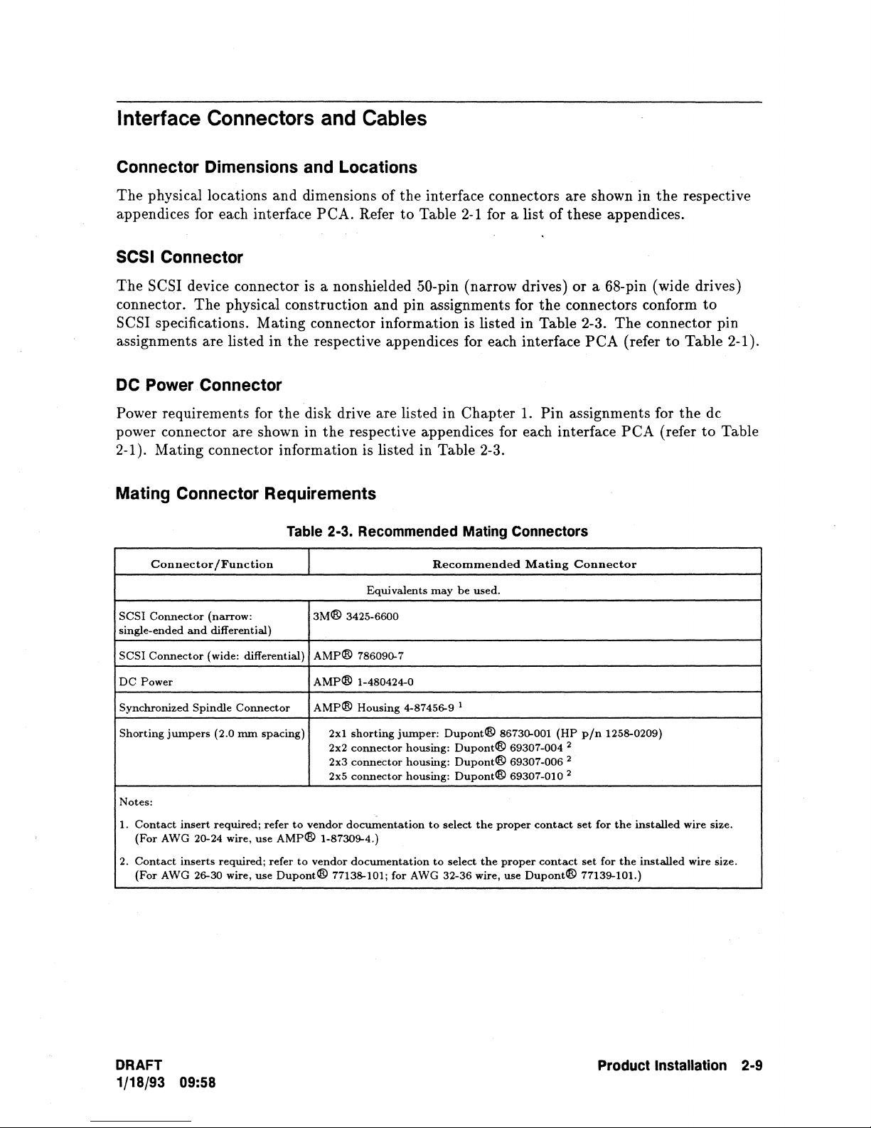
Mating Connector Requirements
Table 2-3. Recommended Mating Connectors
Connector
SCSI
Connector
single-ended
SCSI
Connector
DC
Power
Synchronized
Shorting
Notes:
1.
2.
jumpers
Contact
(For
AWG 20-24 wire,
Contact
(For
AWG 26-30 wire,
/Function
(narrow:
and
differential)
(wide: differential)
Spindle
insert
inserts
Connector
(2.0
mm
required;
required;
spacing)
refer
use
AMP®
refer
use
Dupont®
to
to
3M®
AMP@
AMP@
AMP®
vendor
vendor
Equivalents
3425-6600
786090-7
1-480424-0
Housing
2x1
shorting
2x2
connector
2x3
connector
2x5 COlmector
documentation
1-87309-4.)
documentation
77138-101;
Recommended
may
4-87456-9 I
jumper:
for
Dupont@
housing:
housing:
housing:
to
select
to
select
AWG 32-36 wire,
be
used.
Dupont®
Dupont®
Dupont®
the
the
1.
Mating
86730-001
69307-004 2
69307-006 2
69307-010 2
proper
contact
proper
use
Dupont®
Pin
assignments for
Connector
(HP
pin
1258-0209)
set
for
contact
set
for
77139-101.)
PCA
the
the
(refer
installed
installed
the
dc
to
wire
wire size.
Table
size.
DRAFT
1/18/93 09:58
Product
Installation 2-9
Page 32
Cabling
The
Requirements
disk drive adheres to
specifications. Refer
to
the
cabling requirements and limitations
the
SCSI specifications for additional details.
set
forth in
the
ANSI SCSI
• Cables with a characteristic impedance of 100 ohms
flat
or
twisted
• Cables with a characteristic impedance of
pair
ribbon cable.
90
ohms ±10% are preferred for shielded cables.
±1O%
are recommended for unshielded
• To minimize discontinuities and signal reflections, do not use cables with different
the
impedances on
• A minimum wire size of
distribution of termination power. Note: because
connector designs,
same bus.
28
AWG should be used
a wire size
to
minimize noise effects and ensure proper
of
physical size limitations of current
of
30 AWG should be used for wide differential cabling.
• Cables must be properly terminated.
Single-ended Cable
• A 50-conductor flat cable or 25-signal twisted-pair cable should be used. Cable length
should be equal
to
or
less
than
6.0 meters. This refers
to
internal and external cable length
(except stubs).
• A
stub
length of no more
than
0.1
meter is allowed off
the
main line interconnection within
any connected device.
Differential Cable
• For narrow differential drives, a 50-conductor flat cable
should be used. For wide differential drives,
pair cable should be used. Twisted
should be equal to or less
than
pair
25
meters. This refers to internal and external cable length
a 68-conductor flat cable
cabling
is
or
preferred
25-signal twisted-pair cable
or
34-signal twisted
to
minimize noise. Cable length
(except stubs).
• A
stub
length
of
no more
any connected device.
2-10 Product Installation
than
0.2 meter is allowed off
the
main line interconnection within
1/18/93 09:58
DRAFT
Page 33

Product Features
Introduction
This chapter provides an overall functional description, major assembly descriptions, and a
block diagram description.
3
Functional
This section provides a functional description of
Disk
Format
The head/disk assembly (RDA) contains the magnetic disks (see Figure 3-1). Table
the
physical allocation of the cylinders. Each physical sector can store 512 bytes of user
in
the
standard format. The user can choose
sizes (from
which are
Description
the
RP
C2486A/88A/90A SCSI disk drives.
3-1
to
format the drives using other physical sector
180-744 bytes in increments of 2 bytes). The user can choose logical block sizes
1,
2,
4, or 8 times as large as the physical sector size.
lists
data
Sector Format
The smallest directly addressable storage area on a
is
accomplished when the controller specifies the address of
The formatted sector bytes are allocated as shown in figure 3-2.
Addressing
All
addressing between the disk drive and the host is logical.
converts the logical block address into the appropriate physical address (Le. cylinder, head,
sector), allowing for any sparing operations
blocks larger
physical sectors into the currently specified logical block size.
Structure
that
than
the physical sector size, the drive automatically blocks and deblocks the
data
surface is a sector. Accessing a sector
the
cylinder, head, and sector.
.
The
drive's embedded controller
have been performed. To support logical
'
Error
The disk drives use a Reed-Solomon error correction code (ECC) for detection and correction
of
information, and writes
read operation, the controller generates an 18-byte code from
compares
from
The ECC function is enabled or disabled via the DCR (Disable Correction)
page 01R of the MODE SELECT command. When enabled,
DRAFT
1/18/93
Correction
data
errors. During a write operation,
it
to
the
ECC field, a
09:58
Code
the
the
ECC field created during the write operation.
data
the
ECC function generates
information into the ECC field as
error is detected and the ECC field is used
the
sector is written. During a
the
data
If
the
the
ECC algorithm divides a
18
bytes of
field being read, and
I8-byte code differs
to
correct
Product
bit
ECC
the
data.
in
parameter
Features
3·1
Page 34

sector's
two,
72
contiguous bytes is 65. Therefore,
boundaries of nine contiguous bytes,
contiguous bytes,
been executed (Le. read
The
Span field
Span field value is
bytes-per-interleave by dividing
it
Cyclic Redundancy Check (CRC)
ECC
miscorrection.
assumed,
data
field
into
three interleaves, or rows, with a selectable correction factor of one,
or
three
bytes per'interleave. Mathematically, this converts to a maximum
bits
per
number
up
to
sector. However,
it
will be flagged as unrecoverable after
of
bytes
in
parameter
stated
the
nearest
byte
.
that
the
maximum number of bits
if
an error
it
will be corrected.
retry
count, recalibrations, read with offset, reseek, etc.).
will
be
corrected in an interleave is selectable via
page 01h
of
in bits-per-sector.
it
by 24 (8-bits per byte times
the
'.
MODE
The
value.
is aided by a 2-byte cyclic redundancy check (CRC)
With
the
correction span set
the
calculated probabilities of error misdetection
to
burst
SELECT
ECC
72
bits,
that
is guaranteed
longer
than
65
bits falls exactly within
If
it
spreads across more
the
error correction algorithm has
command.
The
Correction
algorithm converts this value
three
interleaves)
to
decrease
if a random
and
miscorrection are as follows:
the
probability
error distribution is
burst
to
fit
the
Correction
and
size
into
nine
than
to
rounding
of
of
the
nine
error
• Probability
1 x
10-
• Probability
than
less
79
of
misdetection (an error exists,
.
of
miscorrection
47
1 x
10-
.
(an
error
is
detected,
but
Track Sparing
Refer
ta
Table
3-1
far a complete track allocation list.
eight "pools", one located
given zone have been used, the drive will use
to
the
outer
diameter.
Track sparing is implemented for any defect within
may
operation
During a
and
the
logical volume is slipped one
defective
exist in
Format
track
is passed over
operation, "Slip Track Sparing" is used: defective tracks are passed over,
For a Reassign Block operation,
is reassigned
in
a RAM look-up
encounters
to
the
original
to
an
alternate track located in
table
the
defective track,
track
the
and
to
continue
at
the
inside diameter of each zone.
the
header,
and
data
field,
track
the
read continues
or
into
the
"Skip Track Sparing" is used:
the
supplied
it
to
will seek
the
read.
the
servo system prior
to
the
spare cylinders
any
spare pool.
alternate
ECC does
but
The
the
other
not
recognize
it)
is less
is improperly corrected) with
spare cylinders are divided
If
all of
the
spare cylinders in a
in
the
adjacent zones
track. Defects causing a spare
area
within
the
physical sector.
than
spare pool. During subsequent reads,
at
the
next logical track.
the
data
in
the
defective
The
"new" location is maintained
to
seeking. When.
location, read
the
data,
the
and
drive
CRC
into
nearer
the
track
return
is
Look Ahead Reads
The
Look Ahead Read capability can improve
READs by preloading the
READ command. After a READ command is received by
proper
to
track
on
3·2 Product Features
the
the
track
host,
into
same
and
loads
the
the
Look Ahead Read function continues
the
buffer.
track,
If
in subsequent READ requests,
they will already be in
track
buffer with
requested
data
the
into
the
the
performance
data
most
the
buffer. While
to
buffer,
and
likely
the
controller,
read
the
the
host asks for
the
data
of
a drive doing sequential
to
be requested with
the
drive seeks
that
data
is being transferred
remainder of
the
will be
the
current
following blocks
returned
1/18/93 09:58
to
the
next
to
the
DRAFT
the
Page 35

host without the delay of a media access. However, the controller is optimized
requested
If a
data
to
the host as fast as possible.
new
READ command requests
data
not contained in the buffer while
performing a Look Ahead Read, the process is aborted, and the drive will immediately seek
the new track with no effect
unrequested
data
has a lower priority
on
access or transfer performance. Filling the track buffer with
than
delivering requested
data,
Other conditions
the
to
return any
drive is
to
that
may affect completing a full-track READ before receiving the next READ command are: head
position relative to the requested data, transfer size, and the host
tr~nsfer
rate.
Head
The drive executes periodic head alignments
During the
Alignments
Power-On sequence,
to
maintain proper track following tolerances.
the
drive executes a complete calibration and head alignment
for all heads. For subsequent operation, there are two modes for head alignments: the
automatic mode, and
Initiator-controlled mode. In the automatic (default) mode,
the
the
drive automatically implements single head alignments in Seek, Read, and Write commands.
In the Initiator-controlled mode, head alignments are executed upon receipt
of
a Rezero Unit
command.
Head Alignment States
The drive will enter either a head alignment needed or critical
temperature since the last head alignment, or the elapsed time since
Temperature
H a
temperature
defined
thresholds,
needed
state.
the
needed
state. H the
second (higher)
accomplished,
change
the
H a
head
threshold
the
drive
Considerations
exceeds
drive
enters
alignment
temperature
before a
enters
the
the
first
of
the
head
occurs
the
change exceeds
head
alignment
critical
two
factory
alignment
drive cancels
state.
is
the
Under
normal
alignment
drive
enters
alignment
the
expected
drive
enters
head
alignments
reliable
operation
calibrations
occurs
state
Elapsed
conditions,
the
needed
the
time
interval
the
critical
are
under
according
the
Time
Considerations
the
drive
at
preset
state
at
drive
cancels
passes
state.
pre-defined
start-up
to
changes in
last head alignment.
schedules
intervals
these
the
without a calibration,
The
time
at
the
and
after
intervals.
needed
periods
factory
long
term
head
spin-up.
H a
head
state.
between
to
assure
conditions.
H twice
The
the
Head Alignment Modes
The Mode Select command (page 09H, byte 8, bits 6 and 7), allows
head alignment function as follows:
DRAFT
1/18/93
09:58
the
Initiator
to
control
Product Features 3·3
the
Page 36

Drive
State
Automatic
(bit
6 =
Mode
0)
Initiator
Controlled
(bit
6 =
Mode
1)
Norm4/
,
Needed:
CritiC4i:
Perlonn
RezeroUnit
Embed
Write
Rezero
Write
Read,
Rezero
no
automatic
behavior:
bit 7 =0:
command
bit
7 = 1: align: all
Command
single-head alignments
commands.
Unit
bit
7 = 0: align
command
bit
7 = 1: align all
command
Protect
or
Write
Unit
bit
7 = 0: align
command
bit
7 = 1: align all
command
align
current
behavior:
current
until
alignment
command.
behavior:
current
head
heads
heads
heads
Typical Head Alignment Times
alignments.
head
on
next
on
next
--
in
Seek,
head
on
on
next
occurs
head
on
on
next
Rezero
Read,
next
Rezero
on
next
Rezero
Rezero
Unit
and
Rezero
Unit
next
Seek,
Rezero
Unit
Disable
Rezero
Unit
Disable
alignments
Rezero
Unit
Disable
to a head
alignment occurs
Rezero
Unit
automatic
Unit
behavior:
bit
7 = 0: align
command
bit
7 =
1:
Command
automatic
upon
Unit
behavior:
bit
7 = 0:
command
bit
7 = 1: align all
command
automatic
that
Unit
behavior:
bit
7 = 0:
command
bit
7 = 1: align
command
head
alignments.
current
head
on
align
all
heads
on
next
head
alignments.
receipt
of
Rezero
align
current
head
on
heads
on
next
head
needs alignment. Write
align
alignments except for a
on
next
write.
current
head
all
heads
on
next
on
next
Rezero
Rezero
Execute
commands.
next
Rezero
Rezero
Protect
next
Rezero
Rezero
Unit
Unit
Unit
Unit
write
until
Unit
Unit
The time requirements for head alignments will vary according
to
how they are executed.
Some typical values are listed below:
Single
Head
Alignment:
All-Heads Alignment:
13
data
heads
....................
................•.....
110 milliseconds
;.:
..
820 milliseconds
Command Queuing
The
disk drives support the following SCSI command queuing operations:
• Head
• Simple Queue Tag. Instructs the Target
• Ordered Queue Tag. Instructs the Target
of
Queue Tag. Instructs the Target
the
command queue and execute
it
executed. A command in the process of being executed will not be
executes multiple Head-of-Queue commands
to
put
the command
that
follows
at
the front of
immediately following the command currently being
to
in
last-in, first-out order.
put
the command
pre~empted.
that
follows
The Target
at
the end of
command queue. The Target executes multiple Simple-Queue commands in any order
will enable
it
to
minimize actuator seek times
to
block locations if
the
queue algorithm
modifier allows it.
to
put
the command
the
command queue. The Target executes Ordered-Queue commands in the order they were
received. All Simple-Queue commands received prior
to
an
that
follows
Ordered~Queue
at
the
command are
the
that
end of
3·4 Product Features DRAFT
1/18/93 09:58
Page 37

executed before
an Ordered-Queue command are executed after
the
Ordered-Queue command. All Simple-Queue commands received after
the
Ordered-Queue command.
• Clear Queue Message. Clears from
queue for
terminated. All pending
is sent for any of
initiators with
The
additional sense code for
• Abort Tag Message.
the
execution is halted. Any pending
or ending message is sent
active or queued
Command queuing is activated by
a one-byte queue
one-byte queue
are:
20H = Head of Queue Tag
21H
22H
A queue
to
tags
is assigned
to
a LUN, all commands are aborted for
the
specified logical unit (LUN). All active
the
I/O
I/O
processes
device goes
current
I/O
tag
to
the
Bus Free phase following successful receipt
Instructs
process.
I/O
processes are not affected.
tag
message
value
that
= Simple Queue Tag
= Ordered Queue Tag
tag
value can be any hex value from
a LUN. A queue
to
is completed.
tag
status
the
If
and
processes. A Unit Attention condition is generated for all other
that
Unit Attention is: Commands Cleared by Another Initiator.
the
the
target
to
the
initiator. Pending
the
that
specifies
uniquely defines
value becomes available for reassignment after
If
more
the
queue all
data
for
either were active or were queued for
target
status
than
to
has already
or
Target when
the
one command with
that
I/O
that
LUN are cleared.
abort
a tagged command.
started
data
for
the
type
the
I/O
OOh
to
initiator.
processes from all initiators
I/O
processes for
No
.of
this message.
execution
the
I/O
process is cleared
status,
of command queuing, followed by a
FFh.
data,
Initiator
process.
An
Initiator
the
of
and commands for
precedes a command with
The
queue
same queue
in
the
that
LUN are
status
that
The
the
can assign 256 queue
or message
target.
target
I/O
tag
the
tag
clears
process,
and
no
message values
I/O
process
value is sent
The
the
status
other
it
The
Clear Queue and Abort Tag operations are activated by one-byte messages with no
follow-on values. These message formats are:
OEH
= Clear Queue
ODH = Abort
If
an Initiator sends a tagged command
Target will send a Queue Full
and
time,
Untagged commands are also accepted by
• An untagged command sent by an
commands (tagged or untagged) in
• A tagged command sent by an
command already in
The drives will clear
then
Note
Tag
to
a Target when
status
send
the
command again.
the
queue
the
queue in either case.
Error
recovery is an exception
to
required
while a Target is executing a command.
send
to
the
Initiator. The
the
drives with
Initiator
the
Initiator
that
was sent by
an
untagged REQUEST SENSE command if
will not be accepted
queue
that
will not
to
were sent by
be
the
the
the
command queue is full,
Initiator
the
accepted
same Initiator.
above restrictions because
should wait a period of
following restrictions:
if
there are any
the
same
Initiator.
if
there is
an
untagged
"
the
other
the
Initiator
an
error occurs
is
DRAFT
1/18/93 09:58
Product Features 3·5
Page 38

Error Recovery
If
an error occurs while a Target is executing a queued command, the following error recovery
sequence is performed
1.
Target sends a Check Condition
2.
A Contingent Allegiance condition is established for the current Initiator. This means all
commands in
Initiator (normally a
Initiators will be queued normally.
3.
If
QErr=l
Sense commands), all commands in
clearwhich clears
Additional Sense Key
all other Initiators
in the Control Mode Parameter Page
to
ensure proper handling of any commands still in the queue:
status
the
queue are suspended until the next command is received from
REQUEST SENSE command). Commands received from other
the
Contingent Allegiance condition. A Unit Attention condition with
of
Tagged Commands Cleared by Another Initiator is established for
that
had
commands in the-queue.
to
the current Initiator.
OAh
(refer
to
the
Mode Select and Mode
the
queue are aborted upon receipt of a command
the
current
to
an
Current Initiator sends
4.
REQUEST SENSE, it is'executed immediately by the Target.
command other
command is queued or rejected according to normal queuing procedures.
5.
The
Contingent Allegiance condition is removed, and any commands still in the queue are
executed by
Synchronized
Synchronized spindle operation (Master or Slave modes) is enabled via Mode Page 04R. Refer
to
Table
A), for more details about implementing these functions.
2-2
Assembly
The
assemblies in
electronics/controller printed-circuit assembly
mechanical and electromechanical assemblies of the disk drive. The drive electronics/controller
PCA
provides the SCSI interface and all electronic control over the RDA. The following
paragraphs describe
than
the
Target in a normal manner.
Spindle
(Chapter 2), and the Mode Sense/Mode Select command information (Appendix
Descriptions
the
the
next command.
an untagged REQUEST SENSE, error recovery is terminated and the
If
the next command is an untagged
lithe
next command is any
Operation
disk drive include the head/disk assembly (RDA) and the drive
(PCA). The sealed RDA contains
the
major functional components of each assembly.
the
Head/Disk
The head/disk assembly (RDA) contains disks, heads,
circuits, atmospheric controls, vibration isolators, and a spindle assembly. A stainless steel
baseplate and cover provide
sealed and is not field repairable.
Disks
The disks are 3.5-inch (95 mm) diameter aluminum substrates with sputtered thin-film
surfaces.
information.
3·6 Product Features DRAFT
Assembly
Data
is stored on
an
actuator
the
supporting structure for these parts. The entire assembly is
both
surfaces of all disks except for one surface reserved for servo
assembly, head interface
1/18/93 08:58
Page 39
Heads
Thin film
each unit is used
Actuator
A rotary actuator positions the heads. A shipping latch captures the
inside diameter of the disks (away from user data) whenever power is removed from
drive. This prevents the heads from moving over
are spinning, causing
power-up sequence, the processor releases
Head
The head interface circuits (located inside the RDA), process
between the read/write heads and the drive electronics/controller
write drivers which provide the necessary current
read preamplifiers
circuit on the drive electronics/controller
data
and
Latch
Interface
heads in the RDA write and read user data. An additional thin film head in
to
recover the servo information.
Assembly
the
Electronics
that
amplify
heads to
data
fly
at
a safe distance above
the
latch, allowing normal movement of
read from
peA.
the
Additional functions performed by
actuator
data
until power is applied
the
disk surfaces. During
the
data
signals transferred
peA.
to
the heads during write operations, and
These circuits include
disk before transferring
it
arm
and
to
at
the
the
disks
the
the
read/write
the
the
disk
the
heads.
head
interface include head selection and write control.
Atmospheric
Controls
The atmospheric controls in the RDA consist of a breather filter and a recirculating filter.
The breather filter equalizes air pressure within the RDA to ambient air pressure
and
prevents contaminants from entering the RDA. The recirculating filter maintains the internal
cleanliness of
the
RDA.
Vibration
The RDA is mounted on vibration isolators
Isolators
to
protect
it
from high frequency external
vibrations.
Spindle
Assembly
The spindle assembly provides the mechanical mounting for the disks. The spindle rotates on
a bearing system and is driven by an "in
motor is supplied by the spindle driver circuit on the drive electronics/controller
hub" brushless
dc
motor.
The
drive current for the
peA.
DRAFT
1/18/93 09:58
Product
Features 3·7
Page 40

Block Diagram
Refer
to
figure 3-3.
including head positioning,
SCSI Interface
The
SCSI interface is
electronics.
configuration information.
The
SCSI interface handles SCSI protocol without intervention from
and is capable of automatically controlling
each transaction. Full arbitration and disconnectJreselection are implemented by
interface.
It
RAM Buffer
The
RAM buffer contains 256-kilobytes of
the
and
disk must pass through
Disk Controller
The
disk controller coordinates
SCSI interface and
of
data
between
the
accesses
and
the
256-kilobyte
disk controller.
The
drive electronics/controller
data
transfer, spindle speed, and power distribution.
the
direct electrical interface between
handles all SCSI timing and protocol, and
the
static
the
RAM buffer.
the
flow
of
data
the
disk controller.
the
SCSI interface,
static
RAM buffer
It
contains a DMA section which controls
the
buffer RAM
to
PCA
proper sequence of bus phases involved in
RAM. All
by interleaving RAM accesses between
and
match
the
controls
the
transfer
data
the
transfer speeds of
the
operation
SCSI channel
of commands,
the
microprocessor,
transferred between
disk controller.
and
The
the
of
the
drive,
the
drive
status
SCSI interface
the
SCSI
the
the
transfer
DMA
and
host
the
The
disk controller also performs error checking on
RAM buffer and generates ECC on
data
controller also does header verification during
data
transferred from
data
being transferred from
the
RAM buffer
read/write
operations.
to
the
Data Encoder/Decoder
The
primary
Return
1,7)
data
information provided by
normal Read and Write operations.
function of
to
Zero)
transferred
the
datal
clock present on
to
and from
the
Data
Encoder/Decoder is
the
SCSI channel and RLL (Run Length Limited,
the
disk surface. This includes sector length
host during format operations as well as
to
convert between
the
NRZ (Non
and
data
transfers during
Microcontroller
The
microcontroller used on
micro controller is responsible for decoding incoming SCSI commands, controlling
processor
and
the
read/write
the
drive electronics/controller
circuitry, and managing
PCA
is a single-chip device.
the
head alignment function.
the
disk.
the
disk
to
The
content
The
servo
the
3·8
Product
Features
1/18/93
DRAFT
09:58
Page 41
Servo Processor
The
servo processor provides index and start-of-sector timing signals,
movement,
motor
spin-up and speed control, and synchronized spindle operation.
movement control consists of track-to-track seeks, track following,
DC
and
repeatable AC errors. Motor spin-up
drive
motor
current modified by information derived from
Synchronized spindle control is derived from an external sync
position information from
the
disk surface.
and
speed control consists of regulated
the
dedicated servo surface.
input
Data Head Interface
The
data
and
the
head interface processes
the
data
encoder / decoder. This includes head selection, providing analog write
heads,
and
amplification and conversion of impulses from
the
data
signals transferred between
the
Actuator Driver
The
actuator
driver amplifies
resultant current
driver provides
the
control information provided by
to
the
the
actuator.
current necessary
to
operate
the
the
servo processor, and
Servo Timing
and
and
correction for
that
the
heads
to
actuator
controls
actuator
Actuator
is compared
read/write
RLL
data.
assembly.
outputs
both
to
heads
current
The
the
to
The
head
function
into
of
the
position
servo timing circuit is
and
Spindle Motor Driver
The
spindle
in-hub spindle
motor
motor.
driver provides 3-phase current
Power Distribution
The
+5
and +
12
voltages provided by an external dc power supply are
spindle
alerts
in a predefined
motor
the
driver,
other
actuator
circuits when power-on occurs
manner
rotation
to
the
to
amplify and convert impulses from
speed information for
to
the
servo processor.
start,
drive,
and
control
the
the
speed
distributed
driver, analog amplifiers, and digital circuitry. A reset
and
when power is lost. Each circuit responds
reset condition.
servo
to
output
the
of
the
DRAFT
1/18/93
09:58
Product Features 3·9
Page 42
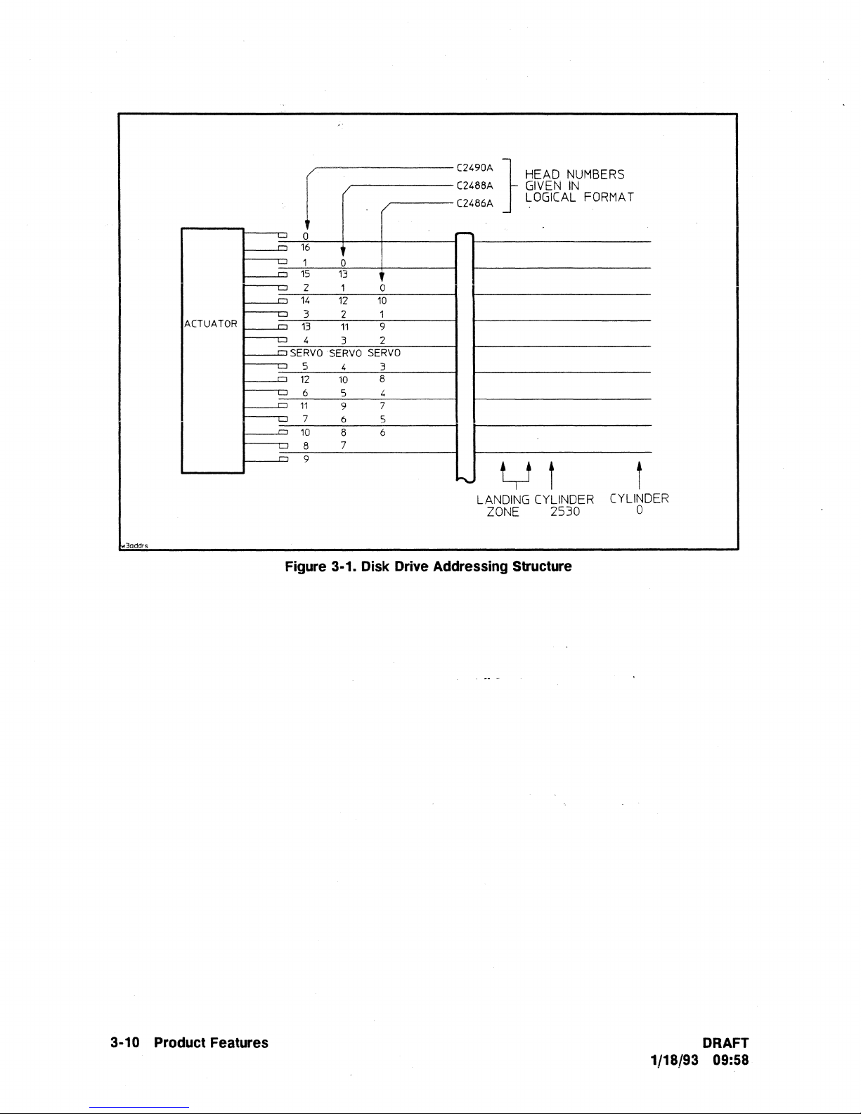
3addrs
ACTUATOR
[
'-'
0
,...,
16
L..J
1
,....,
15
2 1
'-'
,...,
14
3 2
'-'
,...,
13
4
'-'
"""SERVO
5
'-'
,...,
12 10
L-J
6
,...,
11
7 6
'-'
10
'-'
8
,..,
9
0
13
12
11
3
·SERVO
4
5
9
8 6
7
0
10
1
9
2
SERVO
3
8
4
7
5
"490'
C248M
C2486A
r-
}
HEAD
GIVEN
LOGICAL FORMA T
y i i
"'"
LANDING CYLINDER CYLINDER
ZONE
Figure 3·1. Disk Drive Addressing Structure
NUMBERS
IN
2530
0
3-10 Product Features
DRAFT
1/18/93 09:58
Page 43

Table 3·1. C2486A/88A/90A Cylinder Allocation
Function
Zone 0 (Outer
Defect List
Logs,
Mode
Pages
Maintenance
User
Data
Spares
Zone
1
Zone)
Product
C2486A/88A/90A
C2486A/88A/90A
C2486A
C2488A
C2490A 0 4
C2486A
C2488A
C2490A
C2486A
C2488A
C2490A 480
CYlinder(s)
0
0
0
1 o
0
1
1
1
2
thru
479 o
1 4
2
thru
479 o
1
2
thru
479 o
480
thru
493(14
480
thru
493 (14
thru
493 (14
1
ea)
ea)
ea)
Head(s)2
0,1,2
3
4
thru
thru
4
thru
o
thru3
thru
o
thru
thru
4
thru
thru
thru
thru
4
thru
o
thru
o
thru
o
thru
10
3
13
16
3
10
10
13
13
16
16
10
13
16
User
Spares
Zone
User
Spares
Zone
User
Spares
Notes:
1.
Cylinder
2.
Head
Data
2
Data
3
Data
references
references
are
are
given
C2486A 494
C2488A 494
C2490A 494
C2486A 665
C2488A 665
C2490A 665
C2486A
C2488A
C2490A
C2486A
C2488A
C2490A
C2486A 811
C2488A 811
C2490A
C2486A
C2488A
C2490A
given
in
in
physical
logical
format.
format.
thru
thru
thru
thru
thru
thru
67a
thtu
670
thru
670
thru
806
thru
806
thru
806
thru
thru
thru
811
thru
961
thru
961
thru
96lthru
664 o
664 o
664 o
669 (5
ea)
669 (5
ea)
669 (5
ea)
805 o
805
805 o
810 (5
ea)
810
(5
ea)
810
(5
ea)
960
960
960
964 (4
ea)
964 (4
ea)
964 (4
ea)
(continued
o
o
o
o
o
o
o
o
o
o
o
o
o
thru
thru
thru
thru
thru
thru
thru
thru
thru
thru
thru
thru
thru
thru
thru
thru
thru
thru
on
10
13
16
10
13
16
10
13
16
10
13
16
10
13
16
10
13
16
next
page)
DRAFT
1/18/93 09:58
Product Features 3·11
Page 44

'Table 3·1. C2486A/88A/90A Cylinder Allocation (continued)
Zone
User
Spares
Zone
User
Spares
Zone
User
Spares
4
Data
5
Data
6
Data
Function
C2486A
C2488A
C2490A
C2486A
C2488A
C2490A
C2486A
C2488A
C2490A
C2486A
C2488A
C2490A
C2486A
C2488A
C2490A
C2486A
C2488A
C2490A
Product
Cylinder(s)l
965
thru
965
thru
965
thru
1105
1105
1105
1109
1109
1109
1287
1287
1287
1291
1291
1291
1435
1435
1435
1104
1104
1104
thru
1108
(4
thru
thru
thru
thru
thru
thru
thru
thru
thru
thru
thru
thru
thru
thru
ea)
1108
(4
ea)
1108
(4
ea)
1286
1286
1286
1290
(4
ea)
1290
(4
ea)
1290
(4
ea)
1434
1434 o
1434
1439 (5
1439 (5
1439 (5
ea)
ea)
ea)
Head(s)2
o
thru
o
thru
o
thru
o
thru
o
thru
o
thru
o
thru
o
thru
o
thru
o
thru
o
thru
o
thru
o
thru
thru
o
thru
o
thru
o
thru
o
thru
10
13
16
10
13
16
10
13
16
10
13
16
10
13
16
10
13
16
Zone
User
Spares
Zone
User
Spares
Notes:
1.
Cylinder
2.
Head
7
--
Data
8
Data
references
references
are
are
given
given
in
C2486A
C2488A
C2490A
C2486A
C2488A
C2490A
C2486A
C2488A
C2490A
C2486A
C2488A
C2490A
in
physical
logical
fonnat.
fonnat.
1440
1440
1440
1592
1592
1592
1595
1595
1595
1743
1743
1743
thru
1591
thru
1591
thru
1591
thru
1594
(3
thru
1594 (3-ea)
thru
1594
thru
1742 o
thru
thru
thru
thru
thru
ea)
(3
ea)
1742 o
1742
1747
(5
ea)
1747 (5
ea)
1747
(5ea)
(continued
o
thru
o
thru
o
thru
o
thru
o
thru
o
thru
thru
thru
o
thru
o
thru
o
thru
o
thru,16
on
10
13
16
10
13
16
10
13
16
10
13
next
page)
3·12
Product Features
DRAFT
1/18/93 09:58
Page 45

Table 3·1. C2486A/88A/90A Cylinder Allocation (continued)
Zone
User
Spares
Zone
User
Spares
Zone
User
Spares
9
Data
10
Data
11
Data
Function
Product
C2486A
C2488A
C2490A
C2486A
C2488A
C2490A 1894
C2486A
C2488A
C2490A
C2486A 2032
C2488A
C2490A 2032
C2486A
C2488A
C2490A
C2486A 2200
C2488A 2200
C2490A
1748
1748
1748
1894
1894
1896
1896
1896
2032
2036
2036
2036
2200
CYlinder(s)
thru
thru
thru'1893
thru
thru
thru
thru
thru
thru
thru
thru
thru
thru
thru
thru
thru
thru
thru
1
1893
1893
1895
(2
(2
(4
(3
ea)
ea)
ea)
ea)
ea)
ea)
ea)
ea)
ea)
1895
1895 (2
2031
2031 o
2031
2035 (4
2035
2035 (4
2199 o
2199
2199 o
2202
2202 (3
2202 (3
Head(s)2
o
thru
o
thru
o
thru
o
thru
o
thru
o
thru
o
thru
thru
o
thru
o
thru
o
thru
o
thru
thru
o
thru
thru
o
thru
o
thru
o
thru
10
13
16
10
13
16
10
13
16
10
13
16
10
13
16
10
13
16
Zone
User
Spares
Zone
User
Spares
Notes:
1.
Cylinder
2.
Head
12
Data
13
(Inner
Data
references
Zone)
references
are
are
given
C2486A
C2488A
C2490A
C2486A
C2488A
C2490A 2347
C2486A 2349
C2488A
C2490A
C2486A 2529
C2488A 2529
C2490A
given
in
in
physical
logical
fonnat.
fonnat.
2203
2203
2203
2347
2347
2349
2349
2529
thru
2346
thru
2346
thru
2346 o
thru
2348 (2
thru
2348 (2
thru
2348 (2
thru
2528 o
thru
2528 o
thru
2528 o
thru
2530 (2
thru
2530 (2
thru
2530 (2
ea)
ea)
ea)
ea)
ea)
ea)
o
thru
o
thru
thru
o
thru
o
thru
o
thru
thru
thru
thru
o
thru
o
thru
0·dlJ'lll6
10
13
16
10
13
16
10
13
16
10
13
DRAFT
1/18/93
09:58
Product Features 3·13
Page 46

INDEX/SECTOR
) Write
1 4
"Zpdm303
Splice
Bytes
ipost
i Gap
i
14
NOTES:
1.
2.
---~----------.---------.-
Sector
4
Bytes
Data
PLO
Sync
Byles
(00)
FOUR
BYTE
BYTE
BYTE n3: PHYSICAL TRACK ADDRESS LSB
BYTE n4:
~CLUDES
Write
Splice
4
Bytes
Data
Sync
Pattern
1
Byte
(BE)
BYTE HEADER ADDRESS FORMAT
n1:
FLAG BYTE
n2: PHYSICAL
LOGICAL
SPEED TOLERANCE BYTES.
Header
PLO
23
bytes
(00)
Dala
Field
512
Bytes
TRACK
SECTOR
Sync
Data
18
(NUMBERS
ADDRESS
ADDRESS
Header
Sync
Pattern
1
Byte
(BE)
ECC
Bytes
IN
PA TTERN
..
Header
Address'
4
Bytes
Note 1
Data
CRC
2
Bytes
PARENTHESIS REPRESENT
WRITTEN
MSB
Header
2
Data
Pad
6
Byte
(0)
CRC
Bytes
ON
Intersector
7
DISK)
Header
Pad
8
Bytes
(00)
Gap
Bytes
Note 2
)
(
Figure
3·2.
Formatted
Physical
Sector
Allocation
3·14
Product
Features
DRAFT
1/18/93 09:58
Page 47

<:
SCSI
CHANNEL
SCSI
INTERFACE
~;
RAM
BUFFER
~;
DISK
CONTROLLER
"
A
...
.A
"
A
ELECTRONICS/
CONTROLLER
DISK
PCA
DATA
-~
"
ENCODER!
"
"
DATA
DECODER
w2Ddm304
SECTOR
PROCESSOR
i r
SERVO
INDEX
...
DATA
HEAD
POSITION
ACTUATOR
MOTOR
CONTROL
SERVO
INFORMA
HEAD
POSITION
SPEED
TION
SPINDLE
MOTOR
CONTROL
Figure 3·3.
..
MICRO-
CONTROLLER
...
HEAD
ALIGNMENT
ACTUATOR
DRIVER
SERVO
TIMING
SPINDLE
MOTOR
DRIVER
Disk
Drive Block Diagram
/'"'II
r----
i
i
i
I
I
I
I
I
I
I
----------------
DATA
HEAD
INTERFACE
1
r----o
f----D
~
f----D
~
"-
f----D
v
~
~
----
,-
f----DSERVO
~
f----D
r--t::J
~
r--t::J
~
'--
I HALL EFFECT
SENSOR
J
MOTOR
i
DATA
HEADS
r---
=:Jf
FEEDBACK
CURRENT
HDA
DRAFT
1/18/93 09:58
Product Features 3·15
Page 48

Page 49

SCSI Interface
Introduction
4
This chapter describes the implementation
the
HP C2486A/88A/90A Disk Drives. The information includes an overview of
features, options, and commands supported by these products. Any operating characteristics
relevant
the HP C2486A/88A/90A Disk Drives.
Table
which commands are
implementations.
Appendix A provides detailed descriptions of the
These descriptions are in alphabetical order and include Command Descriptor Block
formats,
further command specific details, refer
Appendix B provides descriptions of the Vendor
These descriptions include Command Descriptor Block
device specific information involved in command execution.
Supported
The Target supports
to
SCSI implementation are also discussed. In this manual
1-1
provides a list of all the commands supported by
SCSI implementations and which commands are Vendor Unique
data
formats, and all device specific information involved
Functions
the
following:
of
the Small Computer System Interface, SCSI on
the
Target and identifies
SCSI commands supported by
to
the ANSI SCSI Specification.
Unique commands supported by
(CDB) formats,
the
SCSI
the
term Target refers
the
Target.
(CDB)
in
command execution. For
the
Target.
data
formats, and all
to
• Command Queuing. Command queuing is supported.
• Write Cache. Write caching is supported.
• Arbitration. Full arbitration is supported.
• Disconnect.
significant delay occurring during a
• Linked Commands. Command linking is supported.
DRAFT
1/18/93 09:58
If
allowed, the Target may disconnect after a command is received, and for any
data
transfer operation.
SCSI
Interface 4·1
Page 50

• Power-On Sequence Sequence. At Power-on,
Turn on LED
Microprocessor
Microprocessor RAM Test
Data
Controller Test
ECC
Verification Test
Buffer RAM Test, first 64 bytes
and
Test
Initialize SCSI interface
If
Auto Spin-Up is not enabled:
turn
If
Auto
begin spin-up sequence:
Initialize Servo Processor .
off LED
Spin-Up is enabled:
Start
Test buffer RAM while spindle is gaining speed
Settle heads on track and calibrate servo system
Perform head alignments
Write/Read
Initialize
Initialize Logs
Initialize
Turn off LED and wait for a command
Self Test
and
wait for a command
spindle motor (See Note below)
Test
Spare Table
Saved Pages Information
the
Target performs
the
following:
the
Note: While
(except
subsequent
•
Data
Head Alignment. These drives incorporate
data
head alignments. A full head alignment is executed
alignments may be executed relative
power-on.
• Bus Reset. In response to a SCSI bus reset or Bus Device Reset message,
perform
Turn on LED
Abort
Initialize
Initialize Controller
Initialize
Initialize Logs
Initialize
Turn
REQUEST SENSE and INQUIRY) with a
the
following:
Any Command
SCSI interface
Spare Table
Saved Pages Information
off LED
spindle
REQUEST
and
wait for a command
motor
SENSE command will
is spinning up,
the
to
temperature
the
drive will respond
return
capability
changes
- '
in
Progress (reads/writes are aborted
status
byte
of Check Condition.
a Sense Key Code of Not Ready.
to
perform periodic
at
power-on. ,Subsequent head
and/or
elapsed time since
at
sector boundaries)
to
all commands
the
Target will
The
4·2
SCSI
Interface
DRAFT
1/18/93 09:58
Page 51

• SCSI Messages.
The
following SCSI messages are supported:
Code
(hex)
00 1
01
01
03
00
02
04 1
05 1
06
07
08
09
OA
OB
OC
OD
OE
20 2
21
22 2
80-FF
Notes:
1.
In = Target
2.
2nd
byte
Length
(bytes)
to
Initiator;
indicates
22
The
3*
2*
1
1
1
1
1
1
1
1
2
1
additional
Conunand
Extended
following
Request
Wide
*
added
Abort
Save
Disconuect
Initiator
Abort
Message
No
Message
Linked
Linked
Bus
Abort
Clear
Simple
Head
Ordered
Identify
Out = Initiator
Complete
Message
extended
for
Data
length
Tag
Data
Pointers
Detected
Reject
Operation
Parity
Command
Command
Device
Tag
Queue
Queue
of
Queue
Queue
length
of
Transfer
SDTR
in
error
Reset
Tag
Tag
Tag
to
extended
Message
to
Follow
message
Request
bytes
Error
Complete
Complete
Target.
message
is
supported:
With
.
Flag
Direction!
In
In/Out
In/Out
In/Out
Out
In
In
Out
Out
In/Out
Out
Out
In
In
Out
Out
Out
In/Out
Out
Out
In/Out
•
Status
Codes.
The
following
status
Code
(hex)
byte
codes are supported:
Status
Good
00
Check Condition
02
Busy
08
Intermediate
10
Reservation Conflict
18
Queue Full
28
DRAFT
1/18/93 09:58
SCSI
Interface 4·3
Page 52

Table
4·1.
HP
C2486A/88A/90A
Supported
SCSI
Commands
Command
Access Log
Change
Definition 40
Change
SCSI
Change
Wide
Execute
Fonnat
Inquiry
Interface
Manage
Media
Mode
Mode
Mode
Mode
Read
Read
Read
Read
Read
Read
Read
Read
Reassign
Receive
Reformat
Release
Request
Reserve
Rezero
Data
Unit
Primary
Test
Select
Select
Sense
Sense
(6-byte)
(lO-byte)
Buffer
Capacity
Defect
Full
Headers
Long
Diagnostic
Sense
Unit
ill
SCSI
Control
(6-byte)
(lO-byte)
(6-byte)
(lO-byte)
Data
Blocks
Track
Name
ill
Results
Opcode
(hex)
(Appendix
F2
Cl
C2
FE
04
12
EF
FD
Fl
15
55
lA
5A
08
28 •
3C
25
37
FO
EE
3E
07
IC
ED
17
03
16
01
SCSI
Command
*
*
*
*
*
*
•
*
*
*
*
*
*
•
'.
*
*
*
A)
Vendor
Command
(Appendix
Unique
B)
*
*
*
*
*
*
*
*
*
*
4·4
SCSI
Interface
DRAFT
1/18/93 09:58
Page 53

Table 4·1.
HP
C2486A/88A/90A Supported SCSI Commands (continued)
Command
Name
Opcode
(hex)
Seek (6-byte)
Seek (lO-byte) 2B
Send
Diagnostic
Start/Stop
Synchronize Cache 35
Test
Verify
Write
Write
Write
Write
Write Full
Write Long
Write
Unit
Unit
Ready
(6-byte)
(to-byte)
and
Verify 2E
Buffer 3B
Same
.
·~lB
OB
10
00
2F
OA
2A
FC
3F
41
SCSI
Command
(Appendix
*
*
*
*
*
*
*
*
*
*
*
*
*
A)
Vendor
Command
(Appendix
*
Unique
B)
DRAFT SCSI Interface
1/18/93 09:58
4·5
Page 54

Status Byte
A
status
termination of each command as specified, unless the command is cleared by an
message, by a
format, code values, and code descriptions are shown below.
byte is sent from the Target to the Initiator during the Status phase
Bus
Device Reset message, or by a "hard"
Reset
condition. The
at
the
Abort
status
byte
Byte
00
Value
3
S 4
0
0
0 0 1 0 0
0 1 0 0
0
0
2 1
0 0 0
0 0 1
7
Reserved
Good
Check
Busy
0
Intennediate
6
I
Status
Condition
Status
S
Byte Format
Bit
4
I
Status
I
Byte
3
Code
Status Byte Code Descriptions
Description
Indicates
Caused
to
Check Condition
The
accept a command
to
This
(except
condition
retum.ed,
the
by
be
set.
Target
issue
the
status
the
series will
that
Target
any
The
is
busy.
conunand
is
retum.ed
last
causes
the
chain
be
has
error,
exception,
REQUEST
status
This
from
again
for
GOOD
a Check
of
linked
requested.
successfully
or
SENSE
to
determine
status
is
an
Initiator.
at a later
every
conunand),
conunand
Condition
conunands
abnonnal
conunand
retum.ed
2
I
completed
the
nature
whenever a Target
The
nonnallnitiator
time.
in
unless
an
status
to
is
broken;
I
the
condition
should
be
of
the
a series
error,
exception,
be
set.
no
1 0
conunand.
that
causes
issued
condition.
recovery
of
linked
IT
this
status
further
Reserved
sense
following a
is
unable
action
commands
or
abnonnal
is
not
commands
data
to
is
in
0 1 1 0
0
1
1 0 0
4·6
SCSI Interface
Reservation
0
Queue
Conflict
Full
This
unit
This
Head
I/O
status
that
is
status
oj
Queue
process
is
retum.ed
reserved
is
retum.ed
Tag
is
not
whenever a SCSI
to
another
when
message
placed
in
is
the
device
and
the
queue.
attempts
command
SCSI
device.
a Simple Queue Tag, Ordered
received
conunand
to
access
a logical
Queue
Tag,
or
queue
is full.
The
DRAFT
1/18/93 09:58
Page 55
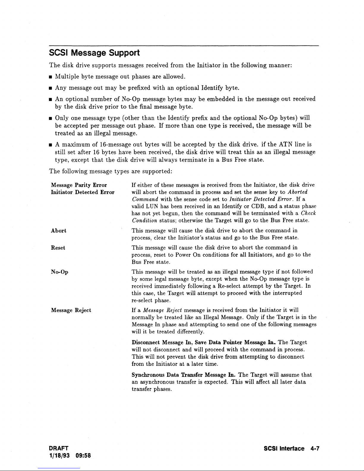
SCSI Message Support
The
disk drive supports messages received from
the
Initiator
in
the
following manner:
• Multiple
byte
message
out
phases are allowed.
• Any message out may be prefixed with an optional Identify byte.
• An optional number
by
the
disk drive prior
• Only one message type
be accepted per message
treated
as an illegal message.
• A maximum of 16-message out bytes will be accepted by
still set after
type, except
The
following message types are supported:
Message Parity
Initiator Detected
Abort
Reset
No-Op
Message Reject
16
that
Error
of
No-Op message bytes
to
the
final message byte.
(other
out
than
phase.
the
If
more
may
be embedded in
Identify prefix and
than
one type is received,
the
bytes have been received, the disk drive will
the
disk drive will always
If
either of these messages
Error
will abort the command in process
Command
valid
has
Condition
This message will cause the disk drive to
process, clear the Initiator's status and go
This message will cause the disk drive
process, reset to
Bus Free state.
This message will be treated
by
some legal message byte, except when the No-Op message type
received immediately following a Re-select
this case, the Target will
re-select phase.
If
a Message Reject message
normally be treated like an Illegal Message.
Message In phase and attempting
will
with the sense code set to Initiator Detected Error.
LUN
has been received in an Identify or CDB, and a
not
yet begun, then the command will be terminated with a Check
status; otherwise the Target will go to the Bus Free state.
it
be treated differently.
terminate
Power On conditions for all Initiators, and go to the
in a Bus Free
is
received from the Initiator, the disk drive
as
an illegal message type if
attempt
is
received from
the
optional N o-Op bytes) will
disk drive.
treat
and
set the sense key to Aborted
to
to
proceed with the interrupted
to
send one of the following messages
the
message
the
if
out
received
message will
the
ATN line is
this as an illegal message
state.
If
a
status
abort
the command in
to
the Bus Free state.
abort the command in
not
attempt
Only if the Target
by the Target. In
the
Initiator
it
phase
followed
will
is
in the
be
is
DRAFT
1/18/93 09:58
Disconnect Message
will not disconnect and will proceed with the command in process.
This
will
not
prevent the disk drive from
from the Initiator
Synchronous
an asynchronous transfer is expected. This will affect all later
transfer phases.
Data
In, Save
at
a later time.
Transfer Message In.
Data
Pointer
The
Message.ln~
attempting
Target will assume
The
to
disconnect
SCSI
Interface 4·7
Target
data
that
Page 56

Extended SDTR Message
Target Error Conditions
The SDTR (SynChronous Data Transfer Request) message type will
only be accepted prior to the
Command phase, and only prior
to
the
first
Command phase in a linked command set. At any other time
it
will be treated as an illegal message type. If the negotiation process
is
started
by
the Initiator, the drive will respond with its SDTR message.
If
the Initiate SDTR Message Option
is
enabled, the drive will initiate
an
SDTR message
a.t
Power On and Reset.
Under some error conditions
the
Target may proceed
to
the
Bus Free phase without
terminating
the
command (i.e. no Disconnect
or
Command Complete message sent
to
the
host). In this case,
the
Target will not
attempt
to re-connect with
the
Initiator.
The
Initiator
should consider this as a catastrophic error. Information regarding
the
cause
of
this abnormal
response can be recovered by
the
Initiator with
the
REQUEST SENSE command.
Message Out Phase Parity Error
If
parity checking is enabled and a message out parity error is detected
the
disk drive will
abort
the
command
in
process and set
the
sense key
to
Aborted Command with
the
sense
code set
to
Parity Error. If a valid
LUN
has been received in an identify or in
the
CDB, and
status
phase has not yet begun, then
the
command will be terminated with a Check Condition
status; otherwise,
the
Target will go the
the
Bus Free
state.
Command
or
Data Out Phase Parity Error
If
parity checking is enabled and a Command or
Data
Out
phase parity error
is
detected then
disk drive will
terminate
the
command in process with a Check Condition status.
The
sense
information will have the sense key set
to
Aborted Command with
the
sense code set
to
Parity
Error.
Illegal Messages
If
an illegal or unexpected message out is received from
the
Initiator,
the
disk drive will
abort
the
command in process and set
the
sense key
to
Aborted Command with
the
sense code set to
Inappropriate/megal Message.
If
a valid LUN has been received
in
an identify or in
the
CDB,
and
the
status
phase has not yet begun, then
the
command will be terminated with a Check
Condition status; otherwise
the
Target will go
to
the
BUS
FREE
phase.
Reselection Timeout
If
the
Target
attempts
to reselect
the
Initiator
and
the
Initiator does not respond within a
Selection Timeout Delay,
the
Target will
attempt
to
reselect a second time.
If
the
second
attempt
fails,
the
Target will
abort
the command
in
process
and
make no further
attempts
to
reselect
the
host.
The
sense information will be set with a sense key of Hardware Error and a
sense code
of
Select/Reselect Failed.
4·8
SCSI
Interface
DRAFT
1/18/93 09:58
Page 57

SCSI Command Descriptions
A
This appendix provides descriptions of
A-I is a list
for each command.
Command
Detailed descriptions of
following pages. These descriptions include Command Descriptor Block (CDB) formats,
formats, and all device-specific information involved
ofthe
SCSI commands supported by
Descriptions
the
SCSI commands supported by
the
SCSI commands supported by
the
Target with brief descriptions included
the
Target are provided in
in
command execution.
the
Target. Table
the
Command Details
The
following information applies
•
The
abbreviations "MSB" and "LSB" in
and
most significant byte
•
The
Target only supports a single Logical Unit Number (LUN). All commands
addressed
•
All reserved fields in each command must be set to
• All reserved and vendor-unique fields in each command are tested for proper values
(normally
to
LUN 0, except an INQUIRY command which
0).
least significant byte, respectively.
to
all commands:
the
CDB
and
O.
other
descriptor blocks refer
may
be directed
must
to
any LUN.
to
data
the
be
DRAFT
1/18/93 09:58
SCSI
Command
Descriptions A·1
Page 58
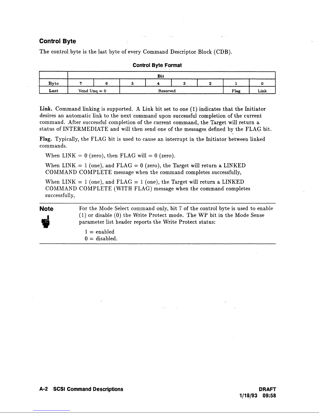
Control Byte
The
control byte is the
last
byte of every Command Descriptor Block (CDB).
Byte
Last
Link. Command linking
7
Vend
I
Unq
6
= 0
is
desires an automatic link to
Control
5
supported. A Link bit set
the
next command upon successful completion of
I
Byte
Bit
4
Reserved
Format
3
I
to
one (1) indicates
2 1 0
I
Flag
that
the
command. After successful completion of the current command, the Target will
status
Flag. Typically, the FLAG bit is used
of INTERMEDIATE and will then send one of
to
cause an interrupt in
the
messages defined by
the
Initiator between linked
commands.
When LINK::: 0 (zero), then FLAG will = 0 (zero).
When LINK
= 1 (one), and FLAG = 0 (zero), the Target will return a LINKED
COMMAND COMPLETE message when the command completes successfully,
When LINK
COMMAND COMPLETE (WITH FLAG) message when
= 1 (one), and FLAG = 1 (one), the Target will return a LINKED
the
command completes
successfully,
Note
For the Mode Select command only, bit 7 of the control byte
(1) or disable
parameter list header reports
(0) the Write Protect mode. The
the
Write Protect status:
WP
bit in the Mode Sense
is
the
Initiator
current
return
the
FLAG bit.
used
to
Link
a
enable
1
= enabled
o = disabled.
A-2
SCSI
Command
Descriptions
DRAFT
1/18/93 09:58
Page 59
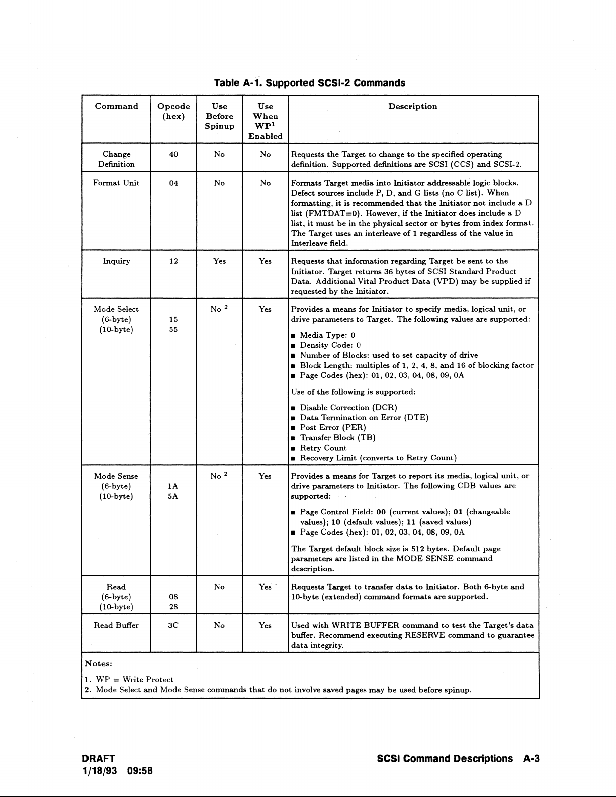
Table
A-1.
Supported
SCSI-2
Commands
Command
Change
Definition
Format
Unit
Inquiry
Mode Select
(6-byte) 15
(to-byte)
Opcode
(hex)
40 No No
04
12
55
Use
Before
Spinup
No No
Yes
No 2
Use
When
Wpl
Enabled
Yes
Yes
Description
Requests
definition.
Formats
Defect sources include P,
formatting,
list (FMTDAT=O). However,
list,
The
Interleave field.
Requests
Initiator.
Data.
requested
Provides a
drive
•
•
•
• Block Length: multiples
•
Use
• Disable Correction
•
•
•
•
• Recovery Limit (converts
the
Target
Supported
Target
media
it
is recommended
it
must
be
Target
Additional
parameters
Media
Density Code: 0
Number
Page
of
the
Data
Post
Transfer Block
Retry
in
uses
an
that
information regarding
Target
by
the
means
Type:
0
of
Blocks:
Codes (hex):
following is
Termination
Error
(PER)
Count
to
change
definitions
into
Initiator
0,
the
physical
interleave
returns
36
Vital
Product
Initiator.
for
Initiator
to
Target.
used
to
of
01,02,03,04,08,09,
supported:
(OCR)
on
Error
(TB)
to
the
specified
are
SCSI (CCS)
addressable logic blocks.
and
G lists
(no C list).
that
the
Initiator
if
the
Initiator
sector
or
of
bytes
to
The
set
1, 2, 4, 8,
(DTE)
to
Retry
bytes
1 regardless
Target
of
SCSI
Data
specify media, logical
following values
capacity
Standard
(VPD)
of
and
Count)
operating
does
from
of
the
be
sent
may
drive
16
of
OA
and
SCSI-2.
When
not
include a 0
include a 0
index
value
to
the
Product
be
supplied
unit,
are
supported:
blocking
format.
in
if
or
factor
Mode Sense
(6-byte)
(IO-byte)
Read
(6-byte) 08 10-byte (extended)
(to-byte)
Read
Buffer
Notes:
1.
WP
= Write
2. Mode Select
Protect
and
Mode
lA
5A
28
3C
Sense commands
DRAFT
1/18/93 09:58
No 2
No
No
Yes
that
Yes'
Yes
Provides a
drive
supported:
•
Page
vaIues)j
•
Page
The
parameters
description.
.
Requests
Used
buffer. Recommend executing
data
do
not
involve saved pages
means
parameters
Control
10
(default values);
Codes (hex):
Target
default block size is 512
are
listed
Target
with
WRITE
integrity.
for
Target
to
Initiator.
Field:
to
transfer
command
BUFFER
to
The
00
(current
01,02,03, 04,08,09,
in
the
MODE
data
formats
command
may
be
used
SCSI
Command
report
its
following
values);
11
(saved values)
bytes.
SENSE
to
Initiator.
are
RESERVE
before
media,
logical
COB
values
01
(changeable
OA
Default
supported.
to
test
command
spinup.
page
command
Both
6-byte
the
Target's
Descriptions
unit,
are
to
guarantee
or
and
data
A-3
Page 60

Table
A-1.Supported
SCSI-2
Commands
(continued)
Command
Read
Capacity
Read
Defect 37
Data
Read
Long
Reassign Blocks
Receive
Diagnostic Diagnostic
Results
Release 17
Request
Sense 03
Reserve
Opcode
(hex)
25 No Yes
3E
07 No No
lC
16
'Use
Before
Spinup
No
No
No
Yes Yes
Yes
Yes Yes
'Use
When
Wpl
Enabled
Enables
logical
supported
Yes
Yes Requests
Yes
Yes
Requests
Target
index
of
Requests
logical
defect list
Requests
Releases previously reserved logical
Release
Only
Pointer
Unit
Reservations
one
Initiator
unit.
Target
returns
format.
Target
physical sector.
Target
unit
supported.
the
and
and
to
Use
of
(REL=O) .
to
P,
G,
to
to
reserved for
contain
the
target
command
Extended
Field
Third-Party
are
not
Description
request
information regarding
PMI
bit
supported.
..
transfer
return
reassign defective logical blocks
only one defect
Extent
Sense
Pointer
media
or
P+G
the
this
purpose.
to
send
the
to
the
initiator.
Release
Data
fields
Reservations
supported.
lists
header,
Format
Relative Addressing
defect
data
in
physical
data
It
is recommended
location
results
of
a previous
units.
Unit
not
supported.
is
supported,
are
not
used.
are
supported.
"
to
sector
field
per
command.
capacity
Initiator.
or
and
ECC
to
Send
and
Third-Party
Extent
bytes
an
The
bytes
area
that
Bit
of
not
from
on
the
Rezero
Seek
(6-byte)
(lO-byte)
Send
Diagnostic
Start/Stop
Synchronize
Cache
Test
Ready
Verify
Notes:
1.
WP = Write
2.
Mode
Unit
Unit
Unit
Select
Protect
and
Mode
01
OB
2B
to
IB
35
00
2F
Sense
commands
No Yes
No
No Yes
Yes Yes
No No
Yes Yes
No No
Yes
that
Requests
logical
address
Requests
lO-byte (extended)
status
when seek is complete.
Self-test (Power-On)
self-test·fails, CHECK
are
available via
Both
modes
Ensures
their
Checks
status
Requests
performing a selectable
addressing
do
not
that
most
Target
if
involve saved pages
Target
to
perform
O.
Target
to
seek
to
formats
and
CONDITION
REQUEST
are
supported.
specified logical blocks
recent
data
value recorded
spindle
for
drive is
up
to
speed.
Target
to
verify
ECC
not
supported.
may
a recalibrate
a specified address.
are
supported.
Translate
SENSE
proper
the
data
check
(REL=O).
be
used
Address
status
command.
in
the
on
speed.
Target
written"on
or a byte
before
and
the
spinup.
then
Both
Target
are
supported.
indicates
cache
memory
media.
returns
the
compare.
to
seek
6-byte
returns
that
media
Relative
to
and
GOOD
IT
results
have
GOOD
by
A-4
SCSI
Command
Descriptions
DRAFT
1/18/93 09:58
Page 61

Table
A·1.
Supported
SCSI·2
Commands
(continued)
Command
Write
(6-byte)
(lO-byte)
Write
And
Verify
Write
Buffer
Write
Write
Notes:
1.
WP = Write
2.
Mode
Long
Same
Select
Opcode
Protect
and
Mode
(hex)
OA
2A
2E
3B
3F
41
Sense
Use
Before
Spinup
No No
No
No
No No Allows
No
commands
Use
When
Wpl
Enabled
No
No
No
that
do
Requests
the
supported.
The
byte
May
avoid
RESERVE
command.
header,
Requests
media
not
media.
Target
compare.
be
possible
involve
Target
Both
perfonns a write
Relative
used
to
data
command
Initiator
data,
and
the
Target
a specified
saved
pages
to
write
6-byte
test
Target's
corruption,
be
to
write
ECC
to
number
may
Description
the
data
and
lO-byte
followed
addressing
data
it
executed
one
complete
fields.
write
the
of
times.
be
used
transferred
(extended)
by
an
not
supported.
buffer
or
is
recommended
prior
to
physical
supplied
before
spinup.
by
formats
ECC
download
the
WRITE
sector,
block
of
the
Intitiator
verify
(REL=O).
code.
that
a
BUFFER
including
data
are
pass
to
To
the
or
to
a
DRAFT
1/18/93 09:58
SCSI
Command
Descriptions
A·5
Page 62
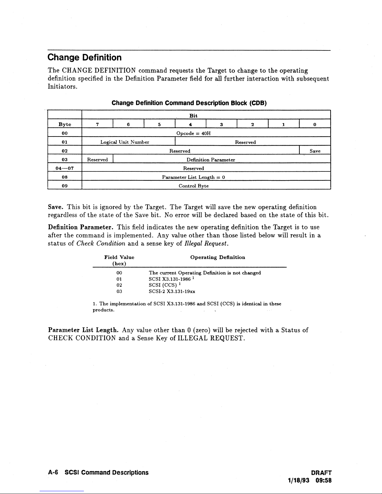
Change
Definition
The
CHANGE DEFINITION command requests
the
Target
to
change
to
the
operating
definition specified in the Definition Parameter field for
all further interaction with subsequent
Initiators.
Change
Definition
Command
Description
Block
(COB)
Bit
Byte
7
I
6
I
5
I
4
I
3
I
2
I
1
I
0
00
Opcode
= 40H
01
Logical Unit
Nwnber
I
Reserved
02
Reserved
I
Save
03
Reserved I
Definition
Parameter
04-07
Reserved
08
Parameter
List
Length
= 0
09
Control
Byte
Save. This
bit
is ignored by
the
Target.
The
Target will save
the
new operating definition
regardless of
the
state
of
the
Save bit.
No
error will be declared based on the
state
of this
bit.
Definition
Parameter.
This field indicates
the
new operating definition the Target
is
to
use
after
the
command is implemented. Any value other
than
those listed below will result in a
status
of Check Condition and a sense key of Illegal Request.
Field
Value
(hex)
00
01
02
03
Operating
Definition
The
CWTent
Operating
Definition is
not
changed
SCSI X3.131-1986 1
SCSI (CCS) 1
SCSI-2 X3.131-19xx
1.
The
implementation
of
SCSI X3.131-1986
and
SCSI (CCS) is identical
in
these
products.
Parameter
List Length. Any value other
than
0 (zero) will be rejected with a
Status
of
CHECK CONDITION and a Sense Key
oflLLEGAL
REQUEST.
A·6
SCSI
Command
Descriptions
DRAFT
1/18/93 09:58
Page 63

Format Unit
Format
The
blocks according
command,
controlled by
instructions (if any) are contained in
phase of
The
can be accessed. Any
lost. Any log information will be cleared by
operating
zero
Unit
FORMAT UNIT command formats
to
the
the
the
command.
FORMAT
parameters
(0).
Initiator
Target may perform a media defect management algorithm (which can be
Initiator
UNIT command ensures
data
will become
defined options. During execution
using optional forms
the
residing on
the
the
saved values
the
Target media
of
the
Defect List supplied
that
the
media is
into
Initiator-addressable logical
of
the
FORMAT
command). Defect management
to
the
formatted
Target
so
that
in
all
media before this command is issued will
the
format operation.
if
the
DSP
bit
The
current Mode Select
in
the
defect
There are four possible sources of defect location information during execution
FORMAT UNIT command:
Plist
(Primary
manufacturer.
Plist is accessible by
the
by
Plist
Initiator
is
not
Clist (Target Certification List). This list includes defects detected
optional certification process executed during
added
to
subject
the
Glist.
Defect List).
The
Plist is stored outside of
the
except through
to
change.
The
Target
list
(to
the
The
of
permanent
the
defects supplied by
Initiator-accessible logical block space.
reference while formatting),
READ
DEFECT
command. Once created,
Format Unit command does
the
FORMAT UNIT command.
but
not
is
not
affect
by
the
the
original
normally accessible
the
Target during an
UNIT
the
data
list
of
the
the
Plist.
This
Data
Out
blocks
be
header is
The
original
list will
be
Dlist
(Data
Defect List). Supplied by
the
Initiator
in
the
Data
Out
phase
of
the
UNIT command.
Glist (Grown Defect List.) Maintained by the Target and includes all defects sent
Target from
current
command.
Byte
00
01
02
03-04
05
FMTDTA
information (Dlist)
there
the
Target will
all previous defect information (Glist)
and
the
FORMAT
The
(Format
will be no
the
CMPLST
Initiator
UNIT
Glist does
7
Logical Unit
Data
not
(the
operations,
NOT
Format Unit Command Descriptor Block (COB)
6
I
Number
Data).
to
Indicates whether
the
Target.
Out
receive a new Dlist,
bit
and
Dlist), any defects identified by
and
any defects identified by a REASSIGN BLOCKS
include
I
(MSB=03)
If
5
set
the
to
Plist.
Bit
4
I
Opcode - 04H
I
FMTDTA I CMPLST
Vendor Unique
Interleave
Control
the
I
Byte
Initiator will send additional defect
zero (0),
phase,
is
retained,
the
Defect List
Format
field will have no effect.
the
3
1
(LSB=04)
Target during previous
I
2
Defect List
1
1
Format
FORMAT
to
the
and
0
I
DRAFT
1/18/93 09:58
SCSI Command Descriptions A-7
Page 64
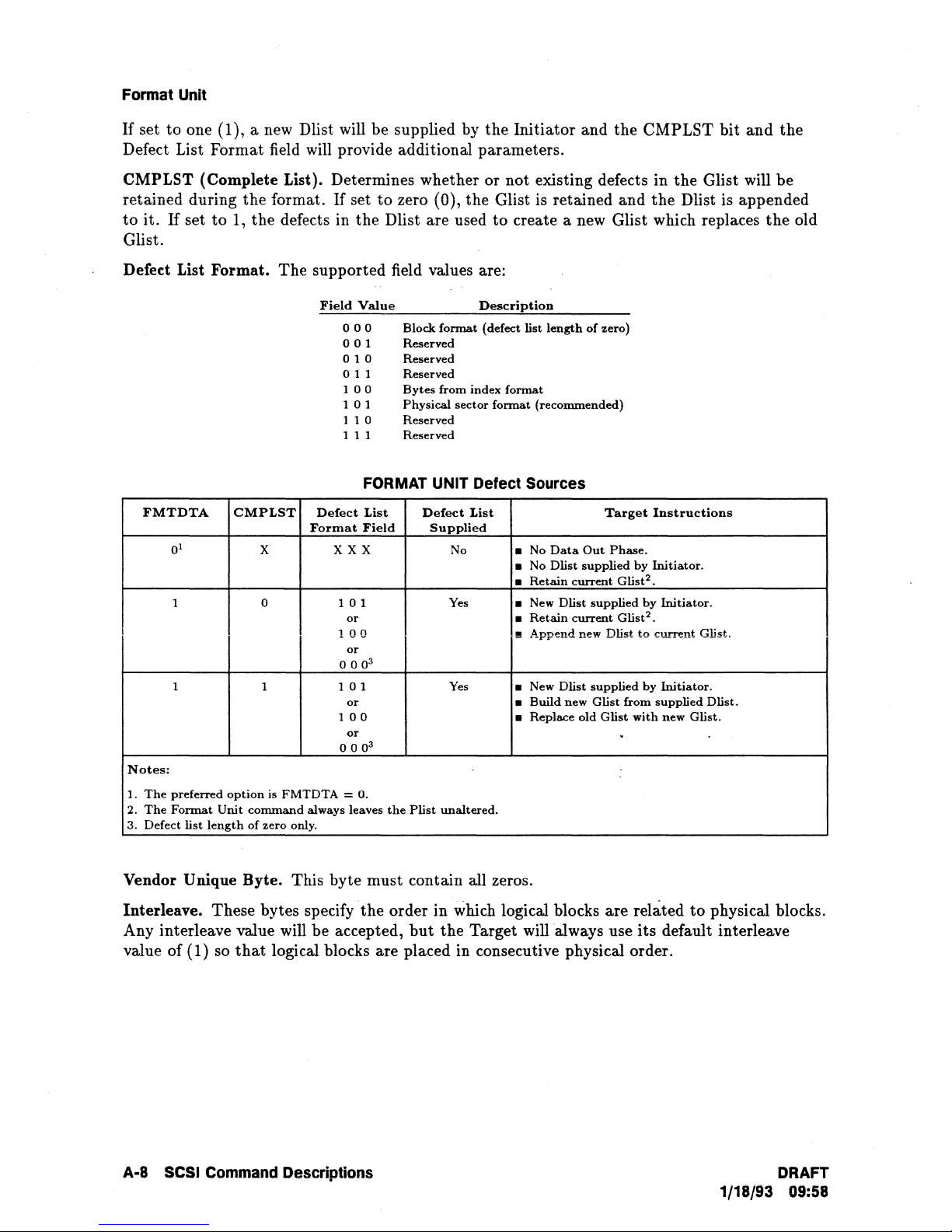
Format Unit
If
set to one (1), a new Dlist will be supplied by the Initiator and the CMPLST bit
Defect List Format field will provide additional parameters.
and
the
CMPLST (Complete List). Determines whether or not existing defects
If
set
to
retained during the format.
to
it.
If
set to
1,
the defects in the Dlist are used
zero (0), the Glist is retained and
to
create a new Glist which replaces
Glist.
Defed
List Format. The supported field values are:
Field
Value
o 0 0 Block
o 0 1 Reserved
format
Description
(defect list
length
of
zero)
o 1 0 Reserved
o 1 1 Reserved
FMTDTA
1
0
1 0
1 1 1
Notes:
1.
The
preferred
2.
The
Format
3. Defect list
CMPLST
option
Unit
length
X
is
FMTDTA
command
of
zero only.
0 0
1
1 0 1 Physical sector
1 1
1 1 1 Reserved
Defect
Format
XXX
101
or
100
or
000
01
or
100
or
000
=
always leaves
Bytes
from index
0 Reserved
format
format
(recommended)
FORMAT UNIT Defect Sources
List
Field
3
3
O.
the
Defect
Supplied
Plist
List
No
Yes
Yes
unaltered.
• No
Data
• No Dlist
•
Retain
New Dlist supplied
•
•
Retain
•
Append
New Dlist
•
•
Build
• Replace
new Glist from
Target
Out
Phase.
supplied
current
current
new Dlist
supplied
old
Glist
by
Glist
Glist
with
.
in
the Glist will be
the
Dlist is appended
Instructions
Initiator.
2
•
by
Initiator.
2
•
to
current
Glist.
by
Initiator.
supplied
Dlist.
new Glist.
the
old
Vendor Unique Byte. This byte must contain all zeros.
Interleave. These bytes specify
Any interleave value will be accepted,
value of (1) so
A-8 SCSI Command Descriptions DRAFT
that
logical blocks are placed in consecutive physical order.
the
order in which logical blocks are related
but
the
Target will ·always use
to
physical blocks.
its
default interleave
1/18/93 09:58
Page 65

Format Unit
Defect List
The defect list consists of a 4-byte header followed by zero or more 8-byte defect descriptors.
Each descriptor consists of an 8-byte physical address or bytes from index address. Each
is
address
bounds-checked by the Target.
REQUEST Sense Key
is
generated, and the format operation is discontinued.
If
any address
is
out of bounds, an ILLEGAL
FORMAT
Byte
00
01 FOV
02-03
7
6
I
DPRY
I
(MSB=02) Defect List Length
FOV (Format Options Valid).
(Disable Primary), DCRT (Disable Certification),
UNIT Defect List Header Format .
Bit
1)
I
DCRT
I
If
the FOV bit is set to one (1), the drive will accept a DPRY
I
I
4
Reserved
STPF
STPF
3
I
IP=O
I
(Stop Format)
2
I
DSP
I
(LSB=03)
1
I
I IMED=O I
and/or
DSP (Disable
I
0
VU=o
Saving Parameter) bites) set to one (1). All other options must be set to zero (0).
DPRY (Disable Primary). A DPRY
the
of
media identified
as
defective in
Target cannot locate the Plist or
action specified by
the
Plist
to
identify defective areas of
nCRT
(Disable Certification). A DCRT
STPF
bit. A DPRY bit of one (1) indicates
the
a media certification operation to generate a
bit
of zero (0) indicates
the
Plist for Initiator addressable logic blocks.
it
cannot determine
the
media. The Plist is not deleted.
bit
of zero (0) indicates
Clist. A DCRT
that
if
a Plist exists,
bit
Target will
it
that
that
the
not
use portions
will perform the
the
target will not use
Target will perform
of one (1), indicates
If
the
that
the
target will not perform any media certification process or format verification operation while
the
executing
STPF
(Stop Format). The
FORMAT UNIT command.
STPF
bit
controls
the
behavior of
the
Target when one
of
the
following events occurs:
1.
The Target has requested the use of
is
set
to
zero) and the Target cannot locate
2.
The target has been requested
(CMPLST is set
A
STPF
bit
of zero (0) indicates
to
zero), and
that,
Target will continue to execute the
CHECK CONDITION status
at
the
Key will be set to RECOVERED ERROR and
DEFECT
ERROR
A
STPF
will terminate
LIST NOT FOUND if condition 1 described above occurs, or
if
condition 2 occurs.
bit
of
one (1) indicates
the
FORMAT UNIT command with a status of CHECK CONDITION, a
that,
the
Plist (DPRY
the
to
use
the
Plist (DPRY
the
Target encounters an error while accessing
if one or
both
is
set
list or determine whether
is
set
of the above conditions occurs, the
FORMAT UNIT command. The Target will
completion of
if one or
the
FORMAT UNIT command.
the
Additional Sense Code will be set
both
of the above conditions occurs,
Sense Key of MEDIA ERROR, and an Additional Sense Code
FOUND
IP
Initialization
it
formats
DRAFT
1/18/93 09:58
if condition 1 occurred,
(Initialization
Pattern).
Pattern
the
media.
or
DEFECT
The IP bit must be set
LIST ERROR
to
zero (0), indicating
will be sent. The Target will use its default initialization
to
zero), or the Glist (CMPLST
the
list exists.
to
zero)
or
the
Glist
the
Dlist.
return
The
DEFECT
LIST
the
of
either
if
condition 2 occurred.
DEFECT
that
no
LIST NOT
pattern
SCSI
Command Descriptions A-9
Sense
to
either
Target
when
Page 66
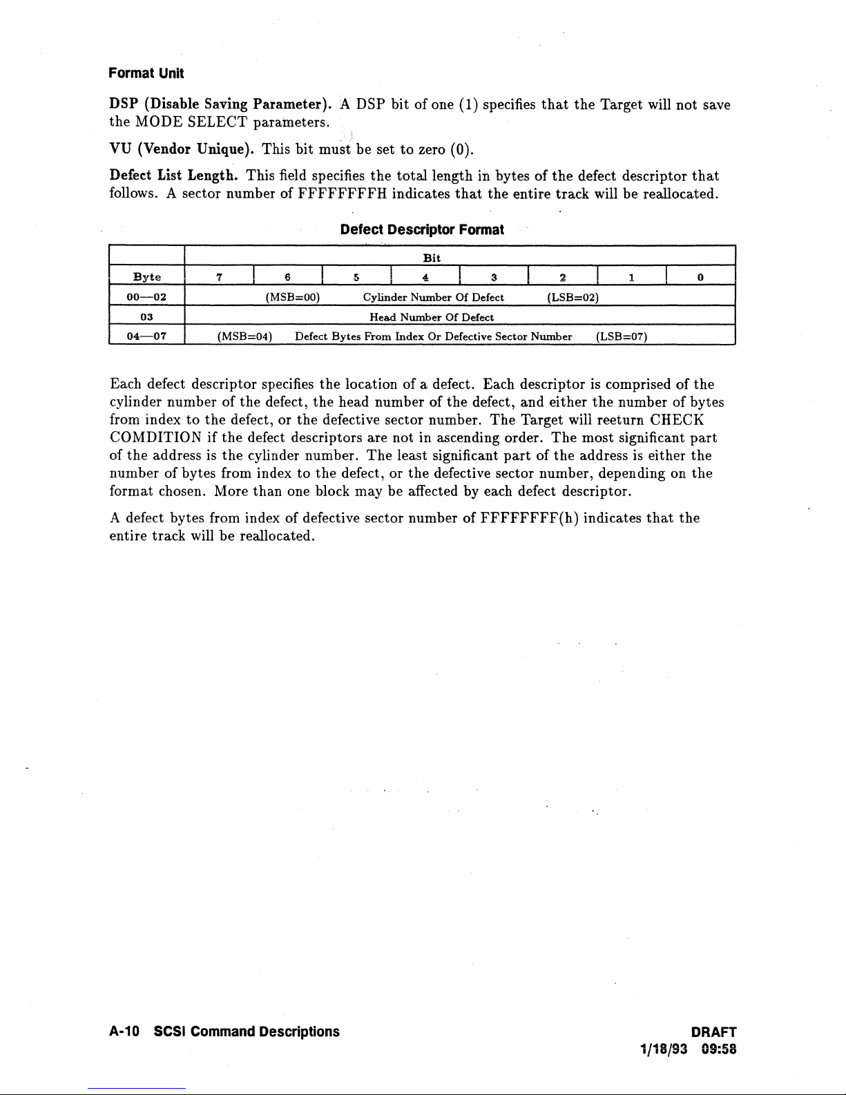
Format Unit
DSP (Disable Saving
the
MODE
SELECT
VU {Vendor Unique}. This
Parameter).
parameters.
bit
must
A DSP
Defect List Length. This field specifies
follows. A sector number of
Byte
00-02
03
04-07
7
1
(MSB=04)
Each defect descriptor specifies
cylinder number of
from index
to
COMDITION if
of
the
address is
the
defect, or
the
the
the
defect descriptors are not in ascending order.
cylinder number.
number of bytes from index
format chosen. More
than
FFFFFFFFH
Defect Descriptor Format
6
(MSB=OO) Cylinder
Defect
defect,
the
to
1>
I
Bytes
the
location of a defect. Each descriptor is comprised of
the
head number of
defective sector number.
the
defect, or
one block may be affected by each defect descriptor.
be set
the
Head
From
The
bit
of one (1) specifies
to
zero (0).
total
length in bytes of
indicates
I
Number
Number
Index
Bit
4,
Or
that
I
Of Defect
Of
Defect
Defective
the
defect,
least significant
the
defective sector number, depending on
that
the
Target will
the
defect descriptor
the
entire
3
Sector
The
part
track
will
be
I
Number
and
2
(LSB=02)
either
1
I
(LSB=07)
the
number of bytes
Target will reeturn CHECK
The
most significant
of
the
address is either
not
save
that
reallocated.
0
J
the
part
the
the
A defect bytes from index of defective sector number of
entire
track
will
be
reallocated.
FFFFFFFF(h)
indicates
that
the
A-10 SCSI Command Descriptions
DRAFT
1/18/93 09:58
Page 67

Inquiry
Inquiry
The INQUIRY command requests
to
the Initiator.
The INQUIRY command will return a CHECK
cannot return the requested Inquiry data. Inquiry
peripheral device may not be ready for other commands. The
execute even
If
an INQUIRY command is received from an Initiator with a pending UNIT ATTENTION
if
the drive is reserved
condition (before the Target reports CHECK
the INQUIRY command and will not clear the
Note
An INQUIRY command directed to an invalid
that
information regarding parameters of the Target be sent
CONDITION status only when the Target
data
will be returned even though the
INQUIRY command will
to
another Initiator.
CONDITION status), the Target will execute
UNIT ATTENTION condition.
LUN
(
=I
0) will return a
Peripheral Device Type of 7FH (Logical Unit Not Present) in byte 0 of
9
Byte
00
01
02
03
04
05
parameter list. This condition is not considered an error. The INQUIRY
if
command will be executed with no error reported even
reserved by
7
(Logical Unit Nwnber)
LUN
Ito
a different Initiator.
Inquiry Command DeSCriptor Block
Bit
I
6
I
5
4
I
Opcode = 12H
I
VPD Page Code
Reserved
Allocation Length
Control
I
Byte
(COB)
3
Reserved
I
the Target is
2
I
1
I
I
the
0
EVPD
EVPD (Enable Vital Product Data) and VPD Identifier. The
VPD Identifier field determine the information
combinations are:
EVPD
bit
If
EVPD is set
to
0 (zero), and the VPD Page Code
Allocation Length. This field specifies the number of bytes
returned Inquiry data. An Allocation Length of zero indicates
transferred. This condition will not be considered as an error. Any other value indicates the
DRAFT
1/18/93
09:58
to
be returned
VPD
Page
Code
o
1
1
1
OOH
OOH
SOH
EOH
Sense
Additional Sense Code: INVALID FIELD IN CDB.
Target
Standard
Supported
Unit Serial Number VPD
Manufacturing Information VPD
Status:
Key: ILLEGAL REQUEST
Will
Inquiry
Parameter
VPD Page List
is
set
CHECK CONDITION
to
Return:
Page
to
1 (one),
that
SCSI
status
of
the EVPD bit and the
the Initiator. The supported
Page
Page
the
Target will return:
the Initiator has allocated for
that
no INQUIRY
Command Descriptions A·11
data
will be
Page 68

Inquiry
maximum number
of
bytes
that
will be transferred. The Target will terminate
the
DATA IN
phase when the specified number of bytes have been transferred or when all available Inquiry
data
have been transferred
Byte
00
01
02
03
04
05-06
07
P
-
/.
i
..
,(.'
1
.'
..
08-15
08
09
10-15
16-31
---
-
16 = C (ASCII)
17
18 = '4 (ASCII)
19
20
21
22
23
24
25-31
32-35
Notes:
1.
For narrow drives, WBUS16 = 0; for wide drives, WBUS16 = 1
7 6 5
...
RMB=O Device
ISO
VER
AENC
RELADR
=1
(MSB=32)
to
the Initiator, whichever is less.
Standard
Peripheral Qualifier
= 0
TRMIOP=O
WBUS32 WBUS16
=0
Inquiry
all zero's = requested LUN is
7FH =
Additional
Note 1
Vendor Identification
Product
0"
--
"
Product
Parameter
Bit
4
,
..
~
(bits
7 - 5) / Peripheral Device
requested
ECMA
Reserved
\
C2486/88: = 8
'::''';'
LUN is
Type
VER=
Parameter
Reserved
SYNC
= H (ASCII)
= P (ASCII)
= ASCII
Identification
= 2
C2490: = 9 (ASCII)
C2486: = 6 (ASCII)
C2488: = 8 (ASCII)
C2490:
Product
Product
Product
Product
0 ANSI
Length
=1
Bytes
Sp~<;eS
Bytes
(ASCII)
(ASCII)
= 0 (ASCII)
ID (ASCII)
ID (ASCII)
ID (ASCII)
ID (ASCII)
ASCII~s
Revision
.....
_ .... _ ........
Number
----)
Page
Format
3 2 1
Type
(bits
supported
not
supported
Modifier = 0
Response
(n=1Fh)
LINKED Reserved
=1
(ASCII)
(ASCII)
(ASCII)
=0
--
.
4 - 0)
Data
Fonnat
CMDQUE
{LSB=35}
VER
=1
0
= 2
= 2
SOFTR
=0
A·12
SCSI
Command
Descriptions
DRAFT
1/18/93 09:58
Page 69

Inquiry
Page Code
OOH:
Supported VPD Page List Format
Bit
Byte
7
I
6
I
5
I
4
I
3
I
2
I
1
I
0
00
Peripheral
Qualifier (bits 7 - 5) /
Peripheral
Device
Type
(bits
4 -
0)
all
zero's =
requested
LUN is
supported
7FH =
requested
LUN is Dot
supported
01
Page
Code =
OOH
02
Reserved
03
Page
Length = 3
04
Page
Code
OOH,
Supported
VPD
Page
List
05
Page
Code
80H, Unit Serial
Number
06
Page
Code EOH,
Manufacturing
Infonnation
Page Code 80H: Unit Serial Number
VPD
Page Format
Bit
Byte
7
I
6
I
5 4
I
3
I
2
I
1
I
0
00
Peripheral
Qualifier = 0 Peripheral Device Qualifier = 0
01
VPD
Identifier = 80H
02
Reserved
03
VPD
ASCII
Data
Length = OAH
04-13
Product
Serial
Number
(ASCII)
DRAFT
SCSI Command Descriptions A·13
1/18/93 09:58
Page 70
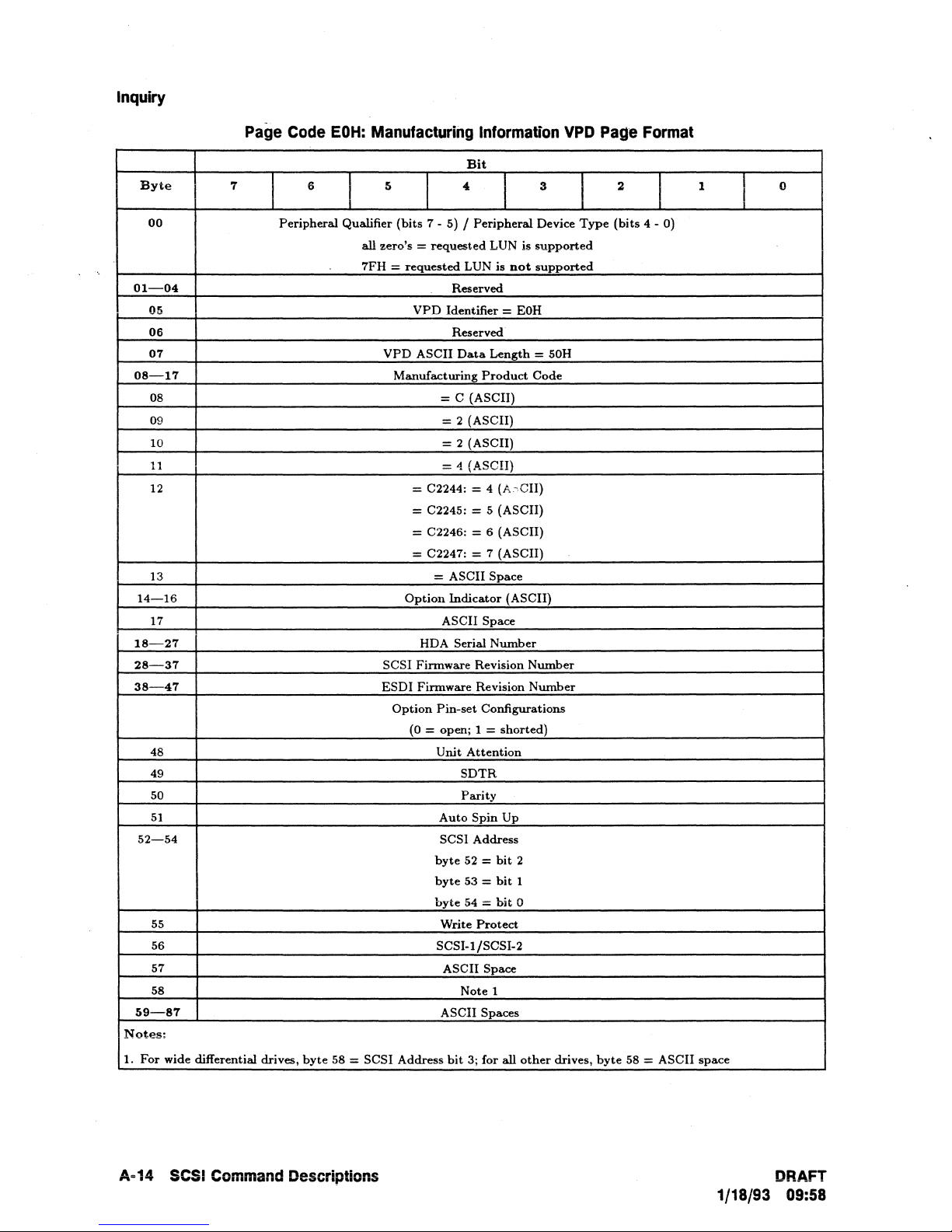
Inquiry
Page
Code
EOH:
Manufacturing
Byte
00
01-04
05
06
07
08-17
08
09
10
11
12
7
6
I
Peripheral
I
Qualifier
all zero's =
7FH =
5
I
(bits
7 - 5) /
requested
requested
VPD
VPD
ASCII
Manufacturing
= C (ASCII)
= C2244: = 4 (A.-CII)
= C2245: = 5 (ASCII)
= C2246: = 6 (ASCII)
= C2247: = 7 (ASCII)
13
14-16
17 ASCII Space
18-27
28-37
38-47
48
49
50
51
52-54
55
56
57
58
59-87
Notes:
1.
For
wide differential drives,
byte
58 =
SCSI
ESDI
SCSI
Option
HDA Serial
Finnware
Finnware
Option
(O
Address
= open; 1 =
= ASCII Space
Pin-set
Unit
Auto
SCSI Address
byte
byte
byte
Write
SCSI-l/SCSI-2
ASCII Spaces
Information
Bit
,
I
Peripheral
LUN is
LUN is
Reserved
Identifier =
Reserved·
Data
Length
Product
= 2 (ASCII)
= 2 (ASCII)
="
(ASCII)
Indicator
Number
Revision
Revision
Configurations
shorted)
Attention
SDTR
Parity
Spin
Up
52 =
bit
53 =
bit
54
:::
bit
Protect
ASCII
Space
Note 1
bit
3; for all
3
Device
supported
not
supported
EOH
= 50H
Code
(ASCII)
Number
Number
2
1
0
other
VPD
I
Type
drives,
Page
2
(bits
byte
Format
I
4 - 0)
58 = ASCII
1
space
0
I
A·14
SCSI
Command
Descriptions
DRAFT
1/18/93 09:58
Page 71

Mode Select, Mode Sense
Mode
Select,
Mode
Sense
The MODE SELECT command provides a means for the Initiator
to
unit, or peripheral device parameters to the Target.
The
MODE SENSE command provides a means for a Target
or peripheral device parameters to the Initiator.
It
is
a complementary command to
to
report its media, logical unit,
MODE SELECT command.
Mode
If
the Target will report CHECK
with Additional
Initiators but not
Select
Command
Description
a MODE SELECT modifies operating parameters
CONDITION status and UNIT ATTENTION Sense Key
Sense Code of MODIFIED PARAMETERS when next accessed by other
by
the Initiator issuing the MODE SELECT command. This rule does
that
are common
NOT override the normal first access rule for each Initiator, nor does
rules for INQUIRY and REQUEST
Mode Select (6-Byte) Command Descriptor Block (COB)
Byte
00
01
02-03
04
05
7
Logical Unit Number
I
6
SENSE.
5
I
(MSB=02)
J
Opcode = ISH
PF
I
Reserved
Parameter
Control
Bit
4
I
I
List Length
Byte
.3
(LSB=03)
J
Reserved
specify media, logical
the
to
other Initiators,
it
override the normal
1
1
I
2
I
0
SP
Byte
02-06
07-08
Note
00
01
09
Mode Select (10-Byte) Command Descriptor Block (COB)
Bit
7
Logical Unit Number
I
6
I
(MSB=02)
(MSB=07)
5
Parameter
I
Opcode
I
Reserved
Control
4
= 5SH
PF
List Length
Byte
I
I
3
(LSB=06)
2
I
Reserved
(LSB=08)
I
1
I
I
0
SP
Bit 7 of the Mode Select control byte will enable (1) or disable (0) the Write
Protect mode. The
the Write Protect status: 1
WP
bit in the Mode Sense parameter list header reports
= enabled, 0 = disabled.
DRAFT
1/18/93
09:58
SCSI Command Descriptions A-15
Page 72

Mode Select, Mode Sense
PF
(Page Format) A
format. When set
both formats are
PF
to
zero (0), the
the
same and
bit
setto
the
one (1) indicates
data
is sent in the vendor unique format. For this product
PF
bit is ignored.
that
the
data
is sent in the
SCSI~2
page
SP (Save Page) Thls bit indicates
If
the
command.
SP bit is set
that
the Target should save any savable pages
to
one (1), the current block size and drive capacity will also be
sent
with this
saved.
Parameter List Length This field specifies the length in bytes
parameter list
zero indicates
that
will be transferred during the
that
no
data
will be transferred. This condition is not considered as an error.
Data
Out
of
the MODE SELECT
phase. A parameter list length
of
non-zero, the parameter length must contain a header and optionally a Block Descriptor (if
is
Block Descriptor Length
8) and optional Parameter Pages.
The currently supported Mode Select Pages are:
Page
Codes
OlH
02H
03H
04H
08H
09H
OAH
Read
Device Disconnect/Reconnect
Direct Access Device
Rigid Disk Drive Geometry
Cache
Peripheral
Control Mode
Parameter
Write
Control
Device
Error
Recovery
Parameters
Parameters
Parameters
Pages
Fonnat
Parameters
Parameters
Parameters
Parameters
The minimum page length accepted is 2 bytes (page code plus length). The Page Length field
must exactly match the values supplied in the Mode
result in a
Additional
Status of CHECK CONDITION, a Sense Key of ILLEGAL REQUEST, and an
Sense Key of INVALID FIELD
IN
CDB.
Sense data. megal parameter lengths will
If
A·16
SCSI
Command Descriptions DRAFT
1/18/93 09:58
Page 73

Mode Select,
Mode
Sense
Mode
Sense
Byte
00
01 Logical
02
03 Reserved
04
05
byte
00
01
02
03-06
07-08
09
Command
Mode Sense (6-Byte) Command Descriptor Block (COB)
7
I
PC
Mode Sense (10-Byte) Command Descriptor Block (COB)
7
I
Logical
PC
Description
6
Unit
Number
6
Unit
Number
(MSB=07)
I
I
I
I
5
Allocation
5
Bit
4
I
Opcode = lAH
Reserved
I
Length
Control
I
Opcode
Byte
Bit
4
= 5AH
I Reserved I
Reserved
Allocation
Control
Length
Byte
3
I
I DBD
Page
3
I
DBD
Page
I
I
Code
I
I
Code
(LSB=08)
2
2
I
Reserved
I
Reserved
1
1
I
I
0
0
DRAFT
1/18/93
09:58
SCSI Command Descriptions A-17
Page 74
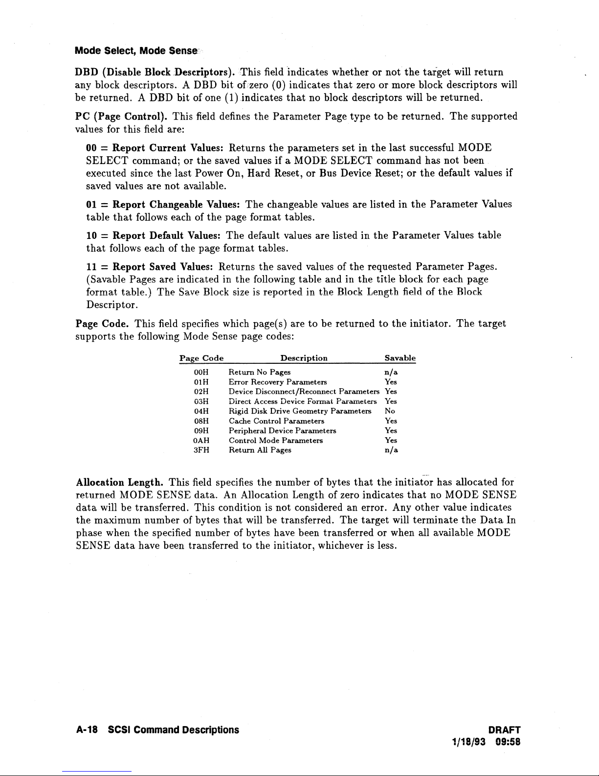
Mode Select, Mode
Sense'>
DBD (Dbable Block
any block descriptors. A DBD bit of:zero (0) indicates
be
returned. A
PC
(Page Control). This field defines the Parameter Page type
Ueseriptors).This
DBDbit
of
one
field 'indicates whether
(l)jndicates
that
that
no block descriptors will be returned.
values for this field are:
00 = Report
SELECT
executed since the last
Current Values: Returns
command; or
the
saved values if a MODE SELECT command has not been
Power On, Hard Reset, or Bus Device Reset; or the default values if
the
parameters set in
saved values are not available.
01
= Report Changeable Values: The changeable values are listed in
that
table
10
= Report Default Values: The default values are listed
that
11
= Report Saved Values: Returns
(Savable Pages
format ta.ble.) The
follows each of the page format tables.
follows each of the page format tables.
the
saved values of
are indicated in the following table and in the title block for each page
Save Block size
is
reported in the Block Length field of
the
Descriptor.
Page Code. This field specifies which page(s) are
supports
the
following Mode Sense page codes:
to
be returned
or
not
the
target will
zero
or
more block descriptors will
to
be returned.
the
last successful MODE
the
in
the Parameter Values table
The
Parameter Values
requested Parameter Pages.
the
Block
to
the initiator. The
return
supported
target
Page
Code
OOH
OIH
02H
03H
04H
OSH
09H
OAH
3FH
Retwn
Error
Recovery
Device Disconnect/Reconnect
Direct
Rigid Disk Drive Geometry
Cache
Peripheral
Control Mode
Retwn
Allocation Length. This field specifies the number of bytes
returned
data
the maximum number of bytes
MODE SENSE data. An Allocation Length of zero indicates
will be transferred. This condition is not considered an error. Any other value indicates
that
will be transferred. The target will terminate the
Description
No
Pages
Parameters
Access Device
Control
All
Parameters
Device
Parameters
Pages
Parameters
Format
Parameters
Parameters
Parameters
that
Savable
nfa
Yes
Yes
Yes
No
Yes
Yes
Yes
n/a
the
initiator has allocated for
that
no MODE SENSE
phase when the specified number of bytes have been transferred or when all available
SENSE
data
have been transferred
to
the initiator, whichever is less.
Data
MODE
In
A·18
SCSI
Command Descriptions
DRAFT
1/18/93 09:58
Page 75
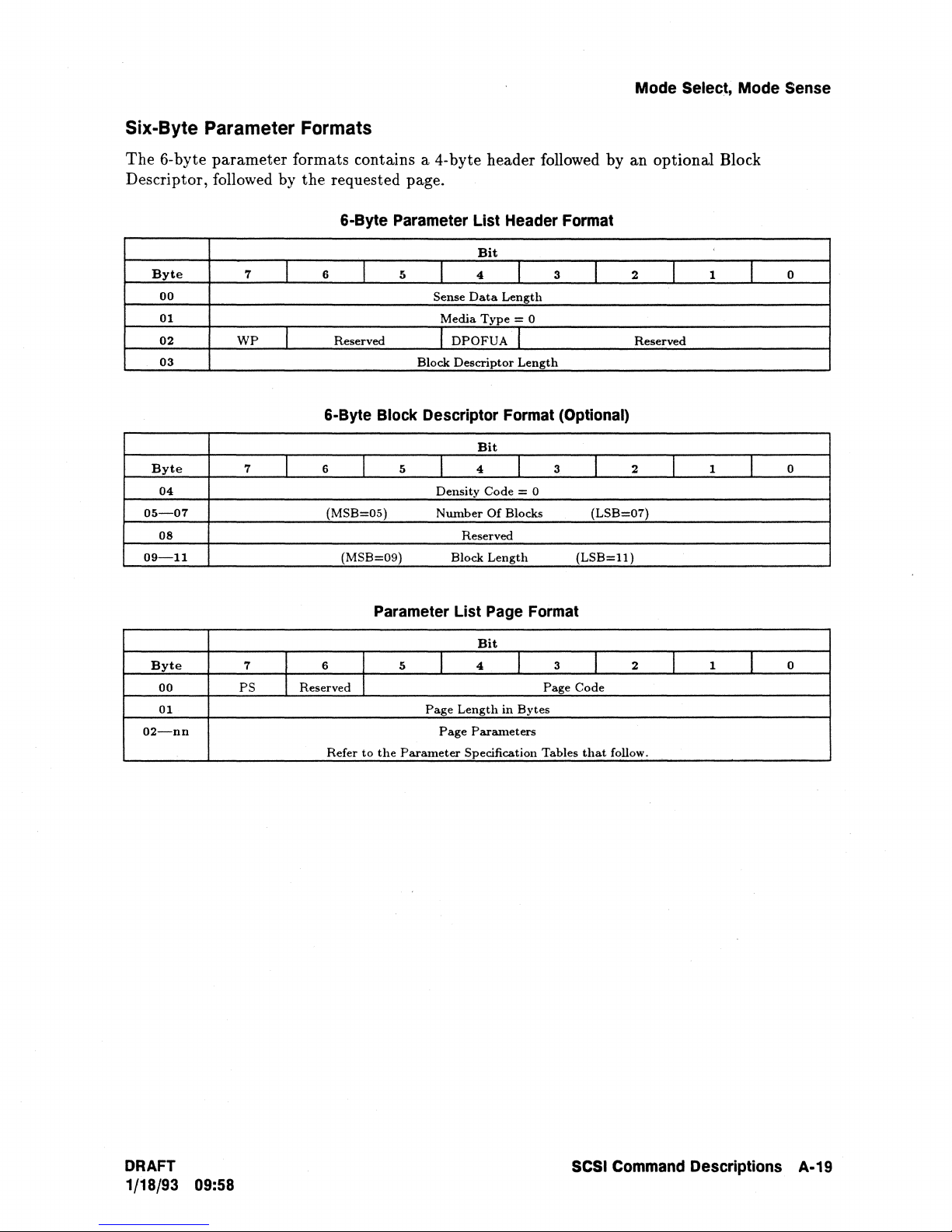
Six-Byte Parameter Formats
Mode Select, Mode Sense
The 6-byte
parameter
Descriptor, followed by
Byte
00
01
02
03
Byte
04
05-07
08
09-11
7
WP
7
I
I
J
formats contains a 4-byte header followed by an optional Block
the
requested page.
6·Byte Parameter List Header Format
Bit
6
Reserved
6·Byte Block Descriptor Format (Optional)
6
(MSB=05)
(MSB=09)
I
I
5
5
I
Sense
Media
I
Block
I
Density
Number
4
Data
Type
DPOFUA
Descriptor
Bit
4
Code
Of
Reserved
Block
Length
I
Length
= 0
I
Length
I
= 0
Blocks
3
3
I
I
(LSB=07)
(LSB=l1)
2
Reserved
2
I
I
1
t
1
J
0
0
Byte
00
01
02-nn
7
PS
6 5
Reserved
Refer
Parameter List Page Format
Bit
4
to
the
Parameter
I
Page
Page
Length
Specification
I
in
Bytes
Parameters
Page
Tables
3
Code
that
I
2
follow.
I
1
I
0
DRAFT
1/18/93 09:58
SCSI Command Descriptions A·19
Page 76

Mode Select, Mode Sense
Ten-Byte Parameter Formats
The
10-
byte
parameter
Descriptor, followed by
Byte
00-01
02
03
04-05
06-07
Byte
08
09-11
12
13-15
7
WP
7
formats contains an 8-byte
the
requested page.
10-Byte Parameter List Header Format
6
I
I
(MSB""06)
I
I
(MSB:::;;OO)
Reserved
10-Byte Block Descriptor Format (Optional)
6
I
(MSB=09)
(MSB:::;;13)
5
5
I
Sense
Media
I
Block
I
Density
Number
Bit
4
Data
Type
DPOFUA
Reserved
Descriptor
Bit
4
Code
Of
Reserved
Block
Length
header followed by an optional Block
I
Length
3
2
I
(LSB:::;;Ol)
I
1
I
= 0
(LSB=07)
2
I
(LSB=ll)
Reserved
I
1
I
I
Len.gth
I
= 0
Blocks
3
(LSB=15)
0
0
Byte
00
01
02-nn
7
PS
I
Reserved
I
6
Refer
Parameter List Page Format
Bit
I
I
to
5
the
Parameter
Page
4
I
Length
Page
Parameters
Specification
in
I
Page
Bytes
..
Tables
3
Code
that
I
2
follow.
J
1
I
0
A-20 SCSI Command Descriptions
DRAFT
1/18/93 09:58
Page 77
Mode Select, Mode Sense
Sense
during the
Data
Length. This field specifies the length in bytes of the page
Data
In phase. The Sense
Data
Length field does not include itself nor does
data
to
be returned
it
include the Block Descriptor length.
Media Type.
WP
(Write
Set to all zeros
Protect).
Indicates whether the drive is in the write protect mode: zero (0) =
to
indicate fixed disk.
write protect disabled; one (1) = write protect enabled. The write protect mode is enabled
or disabled with bit 7 in the Mode
disabled; one (1)
= write protect enabled.
DPOFUA. Indicates whether the target supports
Out)
and FUA (Force Unit Access) in the extended READ command. The
reports
a zero (0) indicating
that
Device Specific Parameters. Not used. Set
Block Descriptor Length. This field specifies the length in bytes of
does not include the
Parameter Pages. The block descriptor length will be either 0 or
Block Descriptor specifies the media characteristics for the entire Logical
Density Code. Not used. Set
Number
of
Blocks. Set to all zeros by MODE SENSE indicating
same size. In MODE SELECT, used by the Set Capacity function
Select command control byte: zero (0) = write protect
the
cache control bits DPO (Disable Page
target
only the FUA bit is supported.
to
all zeros.
the
Block Descriptor, and
Unit.
to
zeros.
that
all blocks are set
to
allow
the
always
8.
Initiator
The
to
to
modify the working capacity of the drive.
The
Set Capacity function is performed by placing a value in the Number of Blocks field of
the
6-
or lO-byte MODE SELECT Block Descriptor. The change
the
drive can be made non-volatile by setting the SP (Save Page)
to
the working capacity of
bit
in the MODE SELECT
Command Descriptor Block to one (1).
Considerations for setting of Number of Block field:
If
set
to
zero (0), the working capacity is not affected.
If
set
to
FFFFFFh,
If set to a value greater than zero
capacity, the working capacity is adjusted
If
set
to
a value greater than
CHECK
CONDITION, a Sense Key oflLLEGAL REQUEST, and an additional Sense Key
of ILLEGAL LOGICAL
Attempting any access beyond the current working capacity
the working capacity is set to maximum.
(0),
but
less than'or-equal
to
the
number of blocks indicated.
the
maximum drive capacity, the drive will set a Status of
BLOCK ADDRESS.
of
to
the
maximum drive
the
drive will result
in
a Status
of CHECK CONDITION, a Sense Key of ILLEGAL REQUEST, and an Additional Sense Key
of ILLEGAL LOGICAL
Block
Length. Indicates logical block size; Set
MODE SELECT, changing the Block Length (or changing
field
in
Mode Page 03H) will reset the working capacity to the maximum.
PS (Page Save). Indicates savable Mode Sense page when set
BLOCK ADDRESS. .
to
user configuration in MODE SENSE. In
the
Data
Bytes per Physical Sector
to
one (1). Ignored for Mode
Select.
Length. Indicates number of bytes remaining in specified page after Page Length field.
Page
DRAFT
1/18/93 09:58
SCSI
Command Descriptions A·21
Page 78

Mode Select, Mode.Sense
Parameter
Specifications
for
Supported
Pages
The following tables list the parameter formats for all supported pages, their respective
default values, and indicates whether the
field
values are changeable or non-changeable with
the Mode Select command.
If
a field
is
changeable, the allowable range is given.
In
addition,
the title block for each page indicates whether the page
is
savable.
A·22 SCSI Command Descriptions
DRAFT
1/18/93 09:58
Page 79

Mode Select, Mode Sense
Page
Byte
00
01
02
03
04
05
06
07
07
08
09
10-11
Code
01H,
ReadfWrite
7
PS
AWRE
6
Reserved
Page
ARRE
SCSI
(MSB=10)
Error
Length
(CCS):
SCSI
SCSI-2
Page
Recovery
5
in
Bytes:
TB
Retry
Data
(CCS):
Bytes
Write
Recovery
01
Parameters
Bit
4
I
SCSI
(CCS)
RC
I
Count;
SCSI-2:
Correction
Head
Strobe
Recovery
H Parameter
Offset
Offset
time
Follow
Reserved
Retry
Reserved
Time
Span
Count
Count
I
Page
= 06;
I
Count
Limit
Limit
Values
3
Code
SCSI-2 = OA
EER
Read
Retry
(last
(Savable
I
= 01H
PER
I
Count
byte)
(LSB=ll)
Page)
2
I
I
1
DTE
I
I
0
DCR
Parameter
AWRE
(Automatic
ARRE
(Automatic
TB
(Transfer Block) 0 Yes o = Disable; 1 =
RC
(Read
Continuous)
EER
(Enable
PER
(Post
Error)
DTE
(Disable
DCR
(Disable
Read
Retry
Correction
Head
Data
Write
Recovery
Recovery
Span
Offset
Strobe
Retry
Time
Time
Write
Reallocation)
Read
Reallocation)
Early
Recovery) 0
Transfer
Correction)
Count
Count
Offset
Count
on
Error)
(Bits
per
Sector)
Count
(SCSI-2 only)
Limit:
SCSI
(CCS)
Limit:
SCSI-2 0000 Yes SCSI-2: 0000 = use
Default
Values Values
(hex)
Changeable
0 Yes o = Disable; 1 =
0 Yes o = Disable; 1 =
data
0
1
0 Yes 1 = Disable; 0 =
0 Yes 1 = Disable; 0 =
08
48
0 No
0 No
8
FF
No
No
Yes o = Disable; 1 =
Yes
Yes
Yes o
No
nla
nla
errors
errors
Maximum
0,24
(I8H).
nla
nla
to
255
SCSI
(CCS):
allowed.
Counts).
Allowable
Enable
Enable
Enable
Enable
Enable
Enable
allowable
retries
72 (48H)
FF = maximum
defaults
Ranges
transfer
posting
transfer
error
correction
= 255
number
(i.e.
of
errored
of
recovered
on
recovered
(FFH)
Retry
of
retrys
DRAFT
1/18/93 09:58
SCSI Command Descriptions A·23
Page 80

Mode Select, Mode Sense
Page Code 02H, Disconnect/Reconnect Parameters (Savable Page)
Bit
Byte
00
01
02
03
04-05
06-07
08-09
10-11
7
PS
6 5
Reserved
Page
Length
(MSB=04)
(MSB=06)
(MSB=08)
in
Bytes;
SCSI
I
SCSI
Buffer Full
Buffer
Empty
Bus
Inactivity
Disconnect
Connect
(CCS):
Reserved (last
4
(CCS):
Ratio
Time
Time
i
Page
= OAH;
Ratio
Limit
Limit
Limit
3
Code
SCSI-2:
bytes)
i
= 02H
(L5B=05)
(LSB=07)
(LSB=09)
2
= OEH
J
1
1
0
10-11
12
13-15
Buffer Full
Buffer
Empty
Bus
Inactivity
Disconnect
Connect
Maximum
DTDC
Control)
Time
(SCSI-2 only;
(MSB=lO)
Parameter
Ratio
Ratio
Limit
Time
Limit
Limit
Burst
Size (SCSI-2 only) 0000
Data
Transfer
Disconnect
SCSI-2
Bytes
Maximum
Reserved
Follow
Burst
Reserved
Size
Page 02H Parameter values
Default
Values
(hex)
CO
co
0004
0000
0000
00
Changeable
Values
Yes
Yes
Yes
Yes
Yes
Yes
Yes
00
00
0000
0000
0000 = No
0000
•
OOB
• 01B = No discolmect
• 11B = No disconnect once
started
• lOB = Reserved
(LSB=l1)
to
FF
to
FF
to
FFFF
to
FFFF
to
FFFF
= Disconnect
until
Allowable
(ignored)
limit
command
I
Range
as
controlled
during
complete
DTDC
data
data
by
ratios
transfer
transfer
A-24 SCSI Command Descriptions
DRAFT
1/18/93 09:58
Page 81
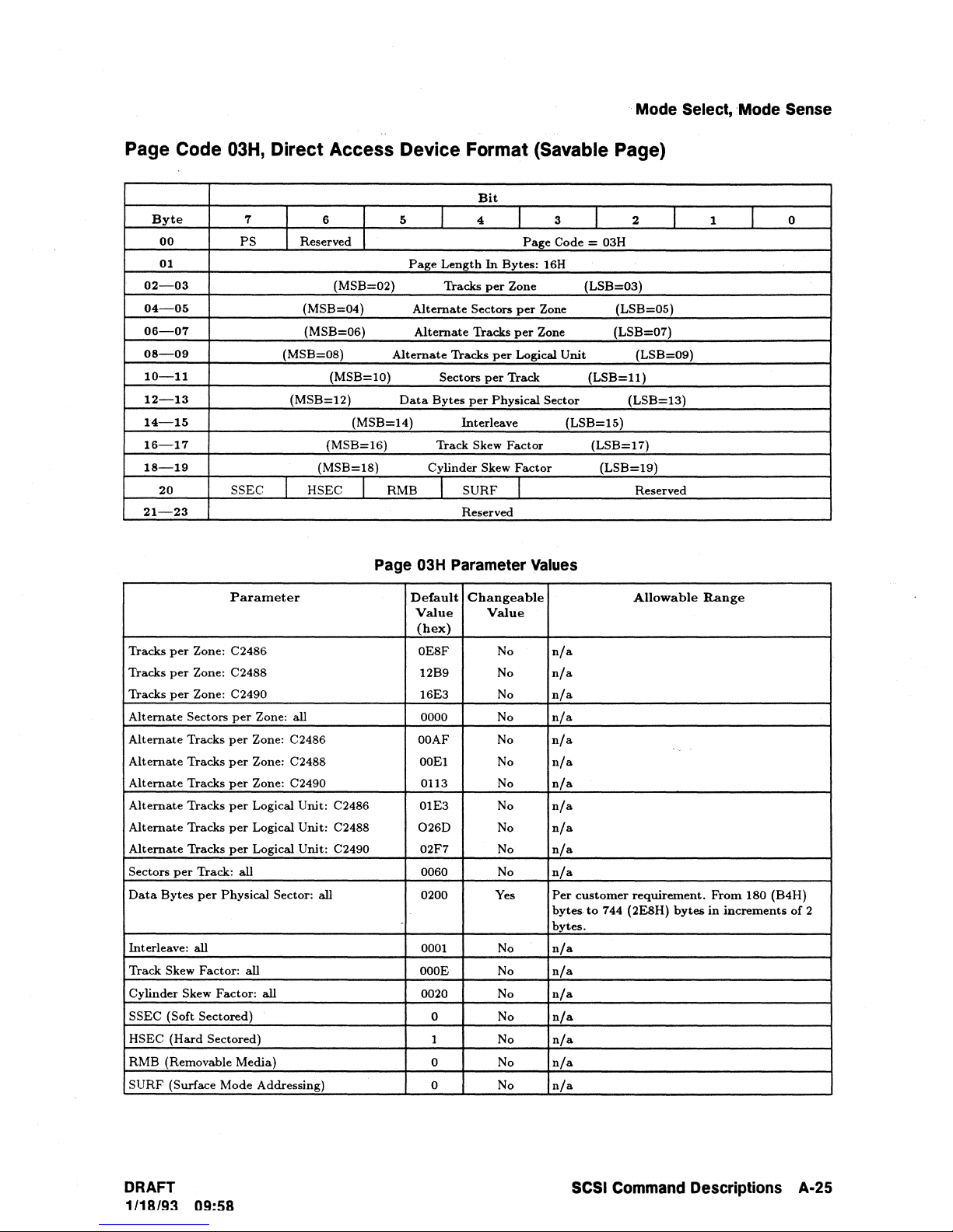
..
Mode
Select,
'Mode
Sense
Page
Tracks
Tracks
Tracks
Alternate
Alternate
Alternate
Alternate
Alternate
Alternate
Alternate
Sectors
Data
Interleave:
Track Skew Factor:
Cylinder Skew Factor:
SSEC (Soft Sectored)
HSEC
RMB (Removable Media) 0
SURF
Code
Byte
00
01
02-03
04-05
06-07
08-09
10-11
12-13
14-15
16-17
18-19
20
21-23
per
per
per
per
Bytes
(Hard
(Surface Mode Addressing)
03H, Direct
7
PS
SSEC HSEC
Parameter
Zone: C2486
Zone: C2488
Zone: C2490
Sectors
per
Zone: all
Tracks
per
Zone: C2486
Tracks
per
Zone: C2488
Tracks
per
Zone: C2490
Tracks
per
Logical Unit: C2486
Tracks
per
Logical Unit: C2488
Tracks
per
Logical Unit: C2490 02F7
Track: all 0060
per
Physical Sector: all
all
all
all
Sectored)
Access
6
Reserved
(MSB=02) Tracks
(MSB=04)
(MSB=06)
(MSB=08)
(MSB=lO) Sectors
(MSB=12)
(MSB=14) Interleave
(MSB=16) Track Skew
(MSB=18)
Device
5
Alternate
Data
RMB
Page
Page
Alternate
Alternate
03H
Default
Value
(bex)
OE8F No
OOAF
0260
Format
Bit
4
I
Length
In
Bytes: 16H
per
Sectors
Tracks
Tracks
per
per
Bytes
per
Physical Sector
Cylinder Skew
SURF
I
Reserved
Parameter
Cbangeable
Value
12B9 No
16E3 No
0000
OOEI
0113
01E3
0200
0001
OOOE
0020 No
0 No
1 No
0 No
No
No
No
No
No
No
No
No
Yes
No
No
No
(Savable
3
I
Page
Code = 03H
Zone
per
Zone
per
Zone
Logical Unit
Track
Factor
Factor
I
values
n/a
n/a
n/a
n/a
n/a
n/a
n/a
n/a
n/a
n/a
n/a
Per
bytes
bytes.
n/a
n/a
n/a
n/a
n/a
n/a
n/a
Page)
I
(LSB=03)
(LSB=07)
(LSB=l1)
(LSB=15)
(LSB=17)
(LSB=19)
customer
to
744 (2E8H)
2
(LSB=05)
(LSB=09)
(LSB=13)
Reserved
Allowable
requirement.
I
bytes
1
Range
From
in
.increments
0
I
180 (B4H)
of
2
DRAFT
1118193
09:58
SCSI
Command
Descriptions
A·25
Page 82

Mode Select,
Mode
Sense
Page Code 04H, Rigid disk Drive Geometry Parameters (Non-Savable Page)
Bit
Byte
00
01
02-04
05
06-08
09-11
12-13
14-16
17-19
7
PS
(MSB=09)
6
Reserved
Page
(MSB=02)
(MSB=02)
(MSB=06)
(MSB=14)
Length
Starting
(MSB=12)
SCSI
5
In
Bytes:
Starting
I
SCSI
Number
Number
Cylinder,
Cylinder,
Drive
Landing
(CCS):
4
(CCS)
Of
Cylinders
Of
Heads
Write
Reduced
Step
Rate
Zone
Cylinder
Reserved
I
Page
= 12H;
Write
(last
3
Code
SCSI-2
Precomp
Current
bytes)
2
I
= 04H
= 16H
(LSB=04)
(LSB=042)
(LSB=08)
(LSB=13)
(LSB=16)
i
(LSB=l1)
1
I
0
17
18
19
20-21
22-23
Number
Number
Number
Number
Starting
Starting
(Not
Drive
Landing
RPL
Locking)
Rotational
SCSI-2
Media
Of
Of
Of
Used)
Step
(SCSI-2 only;
only)
Rotation
Parameter
Cylinders
Heads: C2486 =
Heads: C2488 = 14
Of
Heads: C2490 = 17
Cylinder:
Cylinder:
Zone
Rate
Cylinder
Offset
Write
Reduced
Rotational
(from
Rate
(SCSI-2 only)
11
Precomp
Write
input
(MSB=20)
(Not Used)
Current
Position
sync signal;
SCSI-2
Bytes
Reserved
Media
Follow
Rotational
Reserved
Rotation
Reserved
Offset
Rate
Page 04H Parameter values
0803
OB
OE
11
0000
00
00
1518
Changeable
Values
No
No
No
No
No
No
No
No
Yes
Yes
No
nla
nla
nla
nla
nla
nla
nla
nla
• 00 = No locking
• 01 = Slave
•
0-
revolution
nla
Default
Values
(hex)
000000
000000
000000
(LSB=21)
10 = Master
255
(Note:
of
I
Allowable
each
unit
the
disk.)
RPL
Range
represents
1/256th
A~26
SCSI
Command
Descriptions
DRAFT
1/18/93 09:58
Page 83

Mode Select, Mode Sense
Page Code
Byte
00
01
02
03
04-05
06-07
08-09
10-11
12
13
14-15
16
17-19
OSH,
Cache Control Parameters (Savable Page)
Bit
7
PS
IC
Demand
FSW
6
Reserved
APBF
Read
(MSB=04)
(MSB=06)
(MSB=08)
(MSB=lO)
Reserved
(MSB=14)
(MSB=17)
Retention
5
Page
CAP
Priority
Disable
Maximum
DRA
Number
Non-CaclJe
4 3
1
Length
DISC
I
Pre-Fetch
Minimum
Maximum
Pre-Fetch
I
of
Cache
Cache
Segment
Reserved
In
Bytes
Transfer
Pre-Fetch
Pre-Fetch
Segments
Segment
Page
= 12H
SIZE
Length
Ceiling
Size
Size
I
Code = 08H
I
Write
(LSB=07)
(LSB=09)
Reserved
(LSB=15)
(LSB=19)
2
WCE
Retention
(LSB=05)
(LSB=l1)
I
I
Priority
1
MF
I
1
0
RCD
DRAFT
1/18/93 09:58
SCSI Command Descriptions A·27
Page 84

ModeSelect,Mode
Sense
Page 08H Parameter values
IC
(Initiator
ABPF
(Abort
CAP
(Caching
DISC
(Discontinuity)
SIZE
(Size
WCE
(Write
MF
(Multiplier
RCD
(Read
Demand
Write
Disable
Minimum
Maximum
Maximum
FSW
DRA
Number
Cache
Non-Cache
Read
Retention
Pre-Fetch
(Force
(Disable
of
Segment
Parameter
Control)
Pre-Fetch)
Analysis
Enable)
Cache
Factor)
Cache
Retention
Priority
Pre-Fetch
Pre-Fetch
Pre-Fetch
Sequential
Read-Ahead)
Cache
Segments
Size
Segment
Default
Values
(HEX)
Pennitted)
Enable)
Disable)
Priority
Transfer
Length
Ceiling
Write)
Size 000000
a
-
a
1
1
0
a
a
a
0
a
FFFF
0000
0080
0080
a
a
2
FFFF
Changeable
Values
Yes
No
Yes
No
No
Yes
No
Yes
No
No
Yes
Yes
Yes
Yes
No
Yes
Yes
Yes
No
Allowable
ignored
1 = Use
control
a = Use
nla
ignored
1 =
a = Disable
nla
number
caching
adaptive
Enable
Caching
Caching
n/a
a = Disable; 1 =
nla
1 = Disable; a =
nla
nla
0000 -
FFFF
(ignored)
0000 -
FFFF
logical blocks
0000 -
FFFF
logocal blocks
0000 -
FFFF
(ignored)
nla
a = Enable; 1 =
--
1,2,4,8,
Depends
and
upon
size of
or
16
RAM
Number
nla
of
cache
algorithm
algorithm
Enable
Enable
Disable
buffer
Range
segments
Analysis
Analysis
TFack
of
Cache
in
bytes
Caching
Segments
to
field
A·28 SCSI
Command
Descriptions
DRAFT
1;18/93 09:58
Page 85

Mode Select, Mode Sense
Page Code 09H, Peripheral Device Parameters (Savable Page)
Bit
Byte
00
01
02-03
04-07
08-10
11
7 6 5
PS
Reserved
(MSB=02)
(MSB=08)
Page 09H Parameter values
I
Page
Length
Interface Identifier
Reserved
Interface
Specific
Reserved
4
I
Page
In
Bytes = OAH
Parameters
3
I
Code = 09H
(LSB=03)
2
(LSB=lO)
I
1
I
0
Parameter
Default
Values
(HEX)
Interface Identifier 8000
Interface Specific
Parameters
000000 Yes
Changeable
Values
No 8000 = SCSI
•
•
•
• All
Byte
8,
bit
o =
copy
RAM
1 =
do
lost
on
Byte
8,
bit
o =
enable
1 =
disable
and
execute
commands,
Byte
8,
bit
alignment
o =
align
1 = always
bit 6 state
other
should
be
Allowable
5:
drive
to
media
not
copy
power
6:
Auto-head
automatic
automatic
them
check
7:
Rezero
control
current
align
bit
positions
set
to
error
on
error
log; log
cycle
or
on
bit
Unit
head
all
zero (0)
Range
and
fault
only
contents
bus
alignment
head
head
Rezero
7
command
heads
are
reserved
log from
will
reset
control
alignments
alignments
Unit
head
regardless
and
be
of
DRAFT
1/18/93
09:58
SCSI Command Descriptions A-29
Page 86

Mode Select, Mode Sense
Page
Byte
00
01
02
03
04
05
06-07
Code
OAH,
EECA
Control
7 6
PS
Queue
Reserved
Algoritlun Modifier
Page
Parameter
RLEC
(Report
Queue
Algoritlun Modifier 1
QErr
(Queue
DQue
(Disable Queuing) 0
EECA
(Enable
Allegiance)
RAENP
UAAENP
EAENP
Ready
AEN
Notes:
1.
AEN = Asynchronous
Log
Error
Extended
(Ready
AEN Permission)!
(Unit
Attention
(Error
AEN
Holdoff
Exceptions)
Management)
Contingent
AEN
Permission)l
l
Period
Event
Permission)l
Notification
Mode
OAH
Parameters
5
I
Page
Length
Reserved
Reserved
Ready
AEN Holdoff
Bit
4
In
Bytes
Reserved
(Savable
3
I
Page
Code = OAH
= 06H
I
Reserved
Period
Parameter values (Savable)
Default
Values
(HEX)
0000
0
0
0
0
0
0
Changeable
Values
Yes
Yes
Yes
No
No
No
No
No
No
o = Disable; 1 =
Exception
o =
reordering
0=
nfa
nfa
nfa
nfa
nfa
nfa
Page)
I
-.-
..
!
RAENP
Conditions
Restricted
Continue; 1 =
2
UAAENP
Allowable
Enable
reordering; 1 =
Abort
1 0
QErr
Range
reporting
of Log
Unrestricted
RLEC
DQue
EAENP
A-30 SCSI Command Descriptions
DRAFT
1/18/93 09:58
Page 87

Read
Read
The READ command requests
both
the
accepts
Byte
00
01
02-03
04
05
Byte
00
01
02-05
06
07-08
09
non-extended (6-byte) and extended (lO-byte) CDB formats.
Read (S-Byte) Command Descriptor Block (CDB)
7
Logical
7
Logical
6
I
Unit
Number
(MSB=02)
Read (10-Byte) Command Descriptor Block (CDB)
6
I
Unit
Number
(MSB=02)
(MSB=07)
that
I
I
the
Target transfer
5
I
Opcode
J
Logical Block
Transfer
Control
5
1
Opcode
DPO=O
I
Logical Block
Reserved
Transfer
Control
Bit
4
Bit
4
I
= 08H
Address
Length
Byte
J
= 28H
I
Address
Length
Byte
data
to
the
3
I
Logical Block
3
1
FUA
I
(LSB=08)
Initiator. The Target
2
Address
(LSB=03)
2
Reserved
(LSB=05)
I
(MSB)
I
.1
1
I
I
I
0
0
RelAdr
Logical Block Address. This field specifies
the
logical block
at
which the read operation will
begin.
DPO (Disable Page Out). Not supported. Must be set to 0 (zero).
FUA (Forced Unit Access). A zero (0) instructs the target
a one (1) instructs the target
RelAdr (Relative Address). A one (1) indicates
to
satisfy
data
demand from
that
to
satisfy
the
media.
the
logical block address field is a two's
complement displacement. This negative or positive displacement is
logical block address last accessed on
command. This feature
previous command in
A RelAdr
bit
of zero (0) indicates
is
only available when linking commands. The feature requires
the
linked group has accessed a block of
block of the range of logical blocks
Transfer Length. This field specifies
the
transferred. When using
that
256
indicates
logical blocks will be transferred. When using the extended (lO-byte) CDB
non extended (6-byte) CDB format, a Transfer Length
format, a Transfer Length of zero indicates
condition is not considered an error (no SEEK occurs, and no
data
The most recent
value written in the addressed logical block( s) will be returned.
the
logical unit to form
the
logical block address for this
data
that
the logical block address field specifies
to
be operated on by this command.
the
number of contiguous logical blocks of
that
no logical blocks will be transferred. This
data
data
demand from cache;
to
be added to
the
on the logical unit.
the
first logical
data
to
of
is
transferred).
that
be
zero
a
DRAFT
1/18/93
09:58
SCSI
Command Descriptions A-31
Page 88

Read
Buffer
The READ
as
a diagnostic tool for testing Target memory and
does not alter the media or
contains
Byte
00
01 Logical
02
03-05
06-08
09
Mode. Modes 0
by the
Buffer ID. This field
Buffer Offset. This field
Allocation Length. This
returned data.
BUFFER
command is used in conjunction with the
the
buffer. The
data
a 4-byte header, followed by the buffer data.
Read Buffer Command Descriptor Block
Bit
7
(OOOb)
data
bytes, and Mode 3 returns only the 4-byte header.
An
allocation length of zero specifies
I
6
Unit
Number
(MSB=03)
(MSB=06)
I
5
I
Opcode = 3CH
I
Buffer ID = 0
Buffer Offset = 0
Allocation
4
Control
and 3 (OUb) are supported. Mode 0 returns a 4-byte header followed
is
not supported and should be set
is
not supported and should be set
field
specifies the number of bytes
considered an error. The target will terminate the
bytes or when all available buffer
data
has been transferred, whichever is less.
WRITE
the
SCSI bus integrity. This command
returned by the READ
(COB)
I
Reserved
Length
Byte
that
Data
3
to
zero (0).
to
that
no
data
Phase when the specified number of
2
I
1
(LSB=05)
(LSB=08)
zero (0).
the
initiator has allocated for
be transferred and is not
BUFFER
BUFFER
1
I
Mode
command
command
0
I
Read Buffer Header Format
Bit
Byte
00
01-03
7
I
6
(MSB=Ol)
Available Length. This field may contain up to 262,144 bytes
that
Length of zero indicates
is
the CDB
adjusted
data
The
too small
to
reflect the truncation.
in the buffer may have been altered since the last
recommended
that
to
the Target be placed in reserve or
and subsequent READ
the
test
Target's
data
buffer.
no
allow all of the Available Length, the Available Length field is NOT
BUFFER
5
I
data
transfer will take place.
4
I
Reserved
A vailable
command be linked
I
Length
that
to
3
WRITE
the
ensure
2
1
(LSB=03)
(1
's-based 256K). An Available
If
the
Allocation Length of
BUFFER
WRITE
that
BUFFER
the
1
I
command.
command
initiator can reliably
If any command has been executed by the controller between the execution of the
BUFFER
will be returned. In this case, the sense information
set. The amount of requested buffer
error
A-32 SCSI Command Descriptions DRAFT
command and
status,
but
the
READ
BUFFER
data
command, a status of CHECK CONDITION
will be returned regardless of the MISCOMPARE
the contents should be suspect.
wi11
have a Sense Key of MISCOMPARE
0
I
WRITE
It
is
1/18/93 09:58
Page 89

Read Capacity
Read Capacity
The READ CAPACITY command provides a means for the Initiator
to
request information
regarding the capacity of the logical unit.
Read Capacity Command Descriptor Block
(COB)
Bit
Byte
7
I
6
I
5
I
"
I
3
I
2
I
1
I
0
00
Opcode
= 25H
01 Logical
Unit
Number
I
Reserved
I RelAdr=O
02-05
(MSB=02)
Logical Block Address
(LSB=05)
06-07
Reserved
08
Reserved
I
PMI
09
Control
Byte
PMI
(Partial Media Indicator). A PMI bit of zero (0) indicates
that
the information returned
in
the
READ CAPACITY
Data
phase will be the logical block address and block length (in
bytes) of the
last
logical block of the logical unit. The Logical Block Address field in
the
CDB
must be set
to
zero for this option.
If
the PMI bit is zero (0) and the logical block address
is
not zero, the Target will return a Status of CHECK CONDITION, a Sense Key
of
ILLEGAL
REQUEST, and an Additional Sense Code of ILLEGAL FIELD IN CDB.
A PMI bit of one (1) indicates
that
the information returned in
the
Data
phase will
be
the
logical block address and block length (in bytes) of
the
last logical block address after which
a substantial delay in
data
transfer
will
be encountered. This logical block address shall be
greater than or equal
to
the
logical block address specified in
the
CDB. (Implementor's Note:
This function
is
intended
to
assist storage management software in determining whether there
is sufficient space on the current track, cylinder, etc.
to
contain a frequently accessed
data
structure such as a
file
directory or
file
index without incurring
an
access delay. The address
returned will normally be
the
last block on the addressed track.) .
Read Capacity Data Format
The format
of
the information returned by the Target during
the
Data
In
phase of
the
command is as follows:
Bit
Byte
7
I
6
I
5
I
"
I
3
I
2
I'
1
I
00-03
(MSB=OO) Logical Block Address
(LSB=03)
04-07
(MSB=04)
Block
Length
(LSB=07)
0
DRAFT
SCSI
Command Descriptions A·33
1/18/93
09:58
Page 90
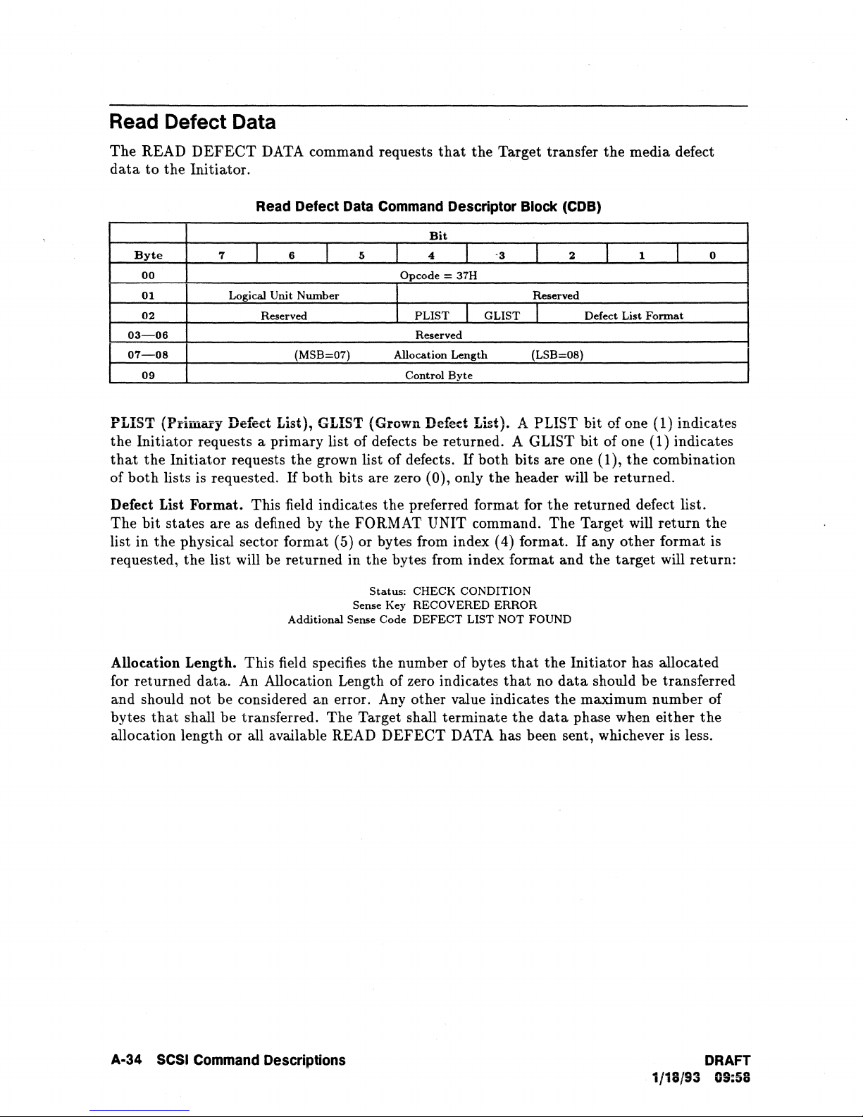
Read Defect Data
The
data
03-06
07-08
READ
to
Byte
00
01
02
09
DEFECT
the
Initiator.
DATA command requests
Read
7
I
Logical Unit
Reserved
Defect
6
J
Number
(MSB=07)
Data
5
that
Command
Bit
4
Opcode = 37H
PLIST
Reserved
Allocation
Control
the
Target transfer
Descriptor
-3
1
GLIST
I
Length
Byte
Block
1
Reserved
I
(LSB=08)
(COB)
2
Defect
the
I
media
1
List
Fonnat
defect
I
0
PLIST (Primary
the
Initiator
that
the
of
both
Defect List
The
bit
list
in
the
requested,
requests a primary list of defects be returned. A GLIST
Initiator
lists is requested.
Format.
states
are as defined by
physical sector
the
list will be
Allocation Length.
for
returned
and should
bytes
that
data.
not
be considered an error. Any
shall
be
allocation length
Defed
requests
List), GLIST (Grown Defect List). A PLIST bit of one (1) indicates
the
grown list
If
both
bits are zero (0), only
This field indicates
the
format
(5)
returned
Additional Sense Code
This
field specifies
An
Allocation Length of zero indicates
of
defects.
the
preferred format for
FORMAT UNIT command.
or
bytes from index (4) format.
in
the
bytes from index format
Status:
Sense Key
the
CHECK
RECOVERED
DEFECT
number
other
transferred.
or
all available READ
The
Target shall
DEFECT
bit
of one (1) indicates
If
both
bits are one (1),
the
header will be returned.
CONDITION
ERROR
LIST
NOT
of
bytes
that
that
value indicates
terminate
the
the
The
and
FOUND
the
no
data
the
data
returned
Target will
If
Initiator
maximum
phase when
any
other
the
target
should
the
combination
defect list.
return
format
will
has allocated
be
transferred
number
either
DATA has been sent, whichever is less.
the
is
return:
of
the
A-34
SCSI
Command
Descriptions
DRAFT
1/18/93 09:58
Page 91

Read Defect Data Defect List Header Format
02-03
00-02
04-07
The
Byte
00
01
Byte
03
.
data
7
7
(MSB=04)
6
I
Reserved
(MSB=02) Defect List
6
I
(MSB=OO)
Sector
Byte
returned by the READ
5
I
I
I
Defect List Descriptor Format
5
I
Number
Index of Defect (Bytes from Index Format)
DEFECT
I
Cylinder
Head Number of Defect
Of
followed by zero or more Defect Descriptors
Read Defect Data
Bit
3
I
"
Reserved
PLIST
Bit
4
Number
Defect (Physical Sector Format) (LSB=07)
DATA
GLIST
I
Length
3
I
Of Defect
command contains a four-byte Header,
2
I
I
(LSB=03)
2
I
(LSB=02)
I
Defect List
I
1
1
Format
..
I
1
0
0
Defed
Descriptors in bytes.
available defect list
List Length. This Header field specifies the total length of
If
the Allocation Length field of
data,
the Defect List Length is NOT adjusted
the
CDB is less
the
following Defect
than
the
to
reflect
the
length of the
truncation.
The defect descriptors are in ascending address order. Ascending address order for physical
sector format is defined as cylinder most-significant and sector least-significant. A sector
number of
The defect
command
cannot be read from the media,
all ones
data
to
(FFFFFFFFH)
is supplied in such a manner
indicates
that
the
entire track has been spared.
that
the list can be issued in a FORMAT
restore the current media reassignment mapping without re-ordering. If the list
the
Target will return:
Status:
Sense
Additional Sense Code:
CHECK CONDITION
Key: MEDIUM
DEFECT
ERROR
LIST
ERROR
DRAFT
1/18/93 09:58
SCSI Command Descriptions A-35
Page 92

Read Long
The READ LONG command requests the Target
Initiator. The
data
transferred will include all header,
to
transfer a specific block of
data,
and ECC (Error Correction
data
to
the
Code) bytes.
Read Long Command Descriptor Block
Bit
Byte
00
01
02-05
06
07-08
09
7
Logical
J
6
Unit
Number
(MSB=02)
(MSB=07)
J
5
4
I
Opcode=
I
Logical Block Address
Reserved
Byte
Transfer
Control
I
3EH
Reserved I
Length
Byte
CORRCT (Corrected). A CORRCT bit of one (1) instructs the Target to correct the
by ECC before transferring
block
to
be read and transferred without any error detection or correction.
it
to
the Initiator. A CORRCT bit of zero (0) causes the logical
3
(COB)
2
I
(LSB=05)
(LSB=08)
I
CORRCT
1
0
I
I RelAdr=O
data
Logical Block Address. This field specifies the starting address for the Read Long operation.
The operation will continue for the length specified by the Byte Transfer Length field.
Byte Transfer Length. This field should specify exactly
transfer.
target
ILLEGAL
Valid and ILl bits will be set
(residue) of
If
a non-zero transfer length does not exactly match the available
will terminate
the
command with a Status of CHECK CONDITION, a Sense Key of
REQUEST, and an Additional Sense Code of INVALID FIELD
to
one (1), and the information field will
the
requested lenght minus the requested length in bytes.
the
number of bytes available for
data
IN
CDB. The
be
set
to
length, the
the
difference
A byte transfer length of zero indicates
considered an error.
A~36
SCS!
Command DeScriptions
that
no bytes will be transferred and wil not
be
DRAFT
1/18/93 09:58
Page 93

Reassign Blocks
Reassign
The
REASSIGN BLOCKS command requests
blocks
logical blocks
be relocated by each defect descriptor sent by
contents
The
The
data
other
to
Byte
00
01
02-04
05
Initiator
Target reassigns
contained
logical blocks on
Blocks
an
area
on
the
to
the
Grown Defect list (Glist). More
or
location
transfers a defect list
7
Logical
in
of
the
Reassign Blocks Command Descriptor Block COB)
I
Unit
the
the
logical blocks specified in
the
the
Target to reassign
logical
unit
reserved for this purpose
than
the
Initiator. This
Primary
6
Number
Defect List (Plist).
5
I
I
Opcode
I
(MSB=02)
that
contains
Bit
4
Reserved
Control
I
=
om
Byte
the
logical block addresses
physical media used for each logical block address in
the
defect list will be lost,
media shall be preserved.
A specific logical block address may be reassigned more
media, a logical block can
locations remain on
the
be
assigned to multiple physical addresses (until no more
media).
and
one physical
3
I
Reserved
(LSB=04)
than
once;
the
defective logical
to
record
or
command
2
I
thus,
over
the
defective
logical block
does
not
alter
1
I
to
be
reassigned.
the
list.
but
the
data
the
life
spare
may
the
0
The
in all
the
Note
REASSIGN BLOCKS command is intended
The
single block defect.
command is
made
provision
to
allow recovery from a
occur on a single track. Therefore,
be
accepted by
the
Target is 96. Duplicate entries in
to
handle multiple defects
the
maximum length defect list
to
situation
The
single spare operation.
Reassign Blocks Defect List Header Format
Bit
Byte
00-01
02-03
The
REASSIGN BLOCKS defect list contains a 4-byte header followed by one
descriptors.
Defect List Length. This field specifies
follow.
does
not
The
include
The
7
length
6
I
of
I
(MSB=02)
each defect descriptor
5
Defect List Length is equal
the
Defect Header length.
I
Defect List
the
total
to
four times
4
I
Reserved
Length
is
four bytes.
length in bytes
the
3
I
(LSB=03)
number
of
the
of
be
used
to
reassign a
in
a single
where multiple defects
that
will
the
defect list result
2
I
1
I
or
more defect
defect descriptors
defect descriptors
and
in
0
that
a
DRAFT
1/18/93 09:58
SCSI Command Descriptions A·37
Page 94
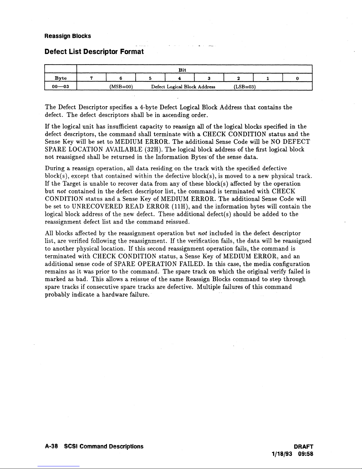
Reassign
Blocks
Defect List Descriptor Format
Bit
Byte
00-03
The
Defect Descriptor specifies a 4-byte Defect Logical Block Address
defect.
If
the
The
logical
defect descriptors,
Sense Key will be set
SPARE LOCATION AVAILABLE (32H).
not reassigned shall be returned in
7
6
I
(MSB=OO)
I
defect descriptors shall
unit
has insufficient capacity
the
command shall terminate with a CHECK CONDITION
to
MEDIUM ERROR.
5
Defect Logical Block Address
be
in ascending order.
the
Information Bytes-of
4
t
to
reassign all of
The
The
J
additional Sense Code will
logical block address of
3
2
I
(LSB=03)
the
logical blocks specified
that
I
contains
be
the
first logical block
the
sense
data.
1
status
NO
0
I
the
in
the
and
the
DEFECT
During a reassign operation, all
that
block(s), except
If
the
Target is unable
but
not contained in
CONDITION
be set
to
status
UNRECOVERED READ
logical block address of
contained within
to
recover
the
defect descriptor list,
and
a Sense Key of MEDIUM
the
reassignment defect list and
All blocks affected by the reassignment operation
list, are verified following
to
another physical location.
terminated
with CHECK CONDITION
the
additional sense code of SPARE OPERATION FAILED. In this case,
it
remains as
was prior
marked as bad.
This
to
allows a reissue of
data
residing on
the
data
from any of these block( s) affected by
ERROR
the
track with
the
specified defective
defective block(s), is moved
the
command is terminated with
(llH),
ERROR.
and
The
additional Sense Code will
the
information bytes will contain
new defect. These additional defect(s) should
the
command reissued.
but
not included in
reassignment.
If
this second reassignment operation fails,
the
command.
If
the
verification fails,
status,
the
a Sense Key of MEDIUM ERROR,
The
spare
track
on which
same Reassign Blocks c-ommand
the
the
to
a new physical track.
the
operation
CHECK
be
added
the
defect descriptor
data
will be reassigned
the
command is
to
and
the
media configuration
original verify failed is
to
step
through
spare tracks if consecutive spare tracks are defective. Multiple failures of this command
probably indicate a hardware failure
..
the
the
an
A-38 SCSI Command Descriptions
DRAFT
1/18/93 09:58
Page 95
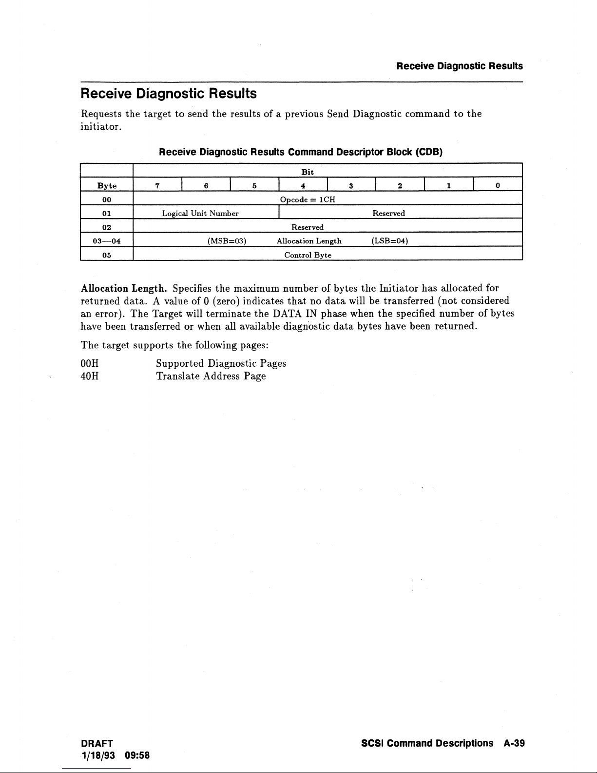
Receive Diagnostic Results
Receive
Requests
Diagnostic
the
target
to
Results
send
the
initiator.
Receive Diagnostic Results
Byte
00
01 Logical
02
03-04
05
7
Allocation Length. Specifies
returned data. A value of
The
an error).
Target will terminate the DATA IN phase when
have been transferred
The
target supports the following pages:
OOR
40R
Supported Diagnostic Pages
Translate Address Page
6
I
Unit
Number
(MSB=03)
the
0 (zero) indicates
or
when all available diagnostic
results
I
of
a previous Send Diagnostic command
Command
Bit
5
I
Opcode
4
I
Reserved
Allocation
Control
maximum number
that
Descriptor Block
3
I
=
lCH
Length
Byte
of
bytes
no
data
will
data
to
the
(COB)
T
1
T
2
I
Reserved
(LSB=04)
the
Initiator has allocated for
be
transferred (not considered
the
specified number
bytes have been returned.
of
0
bytes
DRAFT SCSI
1/18/93 09:58
Command
Descriptions A·39
Page 96

Receive Diagnostic Results
Byte
00
01
02-03
04
05
Byte
00
01
02-03
04
05
06-13
14-21
22-nn
7
7
RAREA
I
I
I
ALTSEC=O I ALTTRK=oj
(MSB=14)
(MSB=14)
Page
OOH:
Supported Diagnostic Page
Bit
6
(MSB=02)
Page 40H: Translate Address Page
6
(MSB=02)
(MSB=06)
5
I
5
I
Reserved
Translated
Translated
I
Page
-Page
Supported
Translate
I
Pagecode
Translated
4
Code = OOH
Reserved
Length:
Page
Address
Bit
4
= 40H
Reserved
Page
Length
Reserved
Address
Address
Address
I
= 0002' ' .
List:
Page:
I
2 (if
required)
n
(if
required)
3
OOH
40H
3
1
I
(LSB=03)
I
(LSB=03)
I
I
(LSB=13)
2
I
2
Supplied
Translated
(LSB=21)
(LSB=nn)
I
1
1
Format
Format
I
1
0
.
0
Suppiied
Formatj
Translated Format. Contains
command Supplied Format field.
RAREA
Addressing.
1 All or
(Reserved Area). Supported when Translated Format field is set
The
bit
indications are:
part
of the translated address
returned Translated Address is
o No
ALTSEC
part
of
(Alternate
the
translated address is within a reserved
Sedor),
and ALTTRK
o (zero).
Translated Address. Contains
in
the
SEND DIAGNOSTIC command.
DIAGNOSTIC
•
If
the
Logical Block Format is specified:
the
block address will be in
and
the
•
If
the
Physical or Logical Sector Formats are specified,
covers more
the
target
DIAGNOSTIC
Translate Format field .
remaining bytes
than
one address after translation:
will
return
Address
the
will
all posible addresses contained in
To
is
FFFF
(Alternate
address( s)
the
first four bytes of
be
set
The
to
0 (zero) .
the
data
Translate field.
the
value from
within a reserved
with
the
remaining bytes filled with zeros.
the
area
area
Track). Not Supported. Will
Target translated from
will be in
the
field,
and
the
format specified in
the
the
area specified in
SEND DIAGNOSTIC
to
Logical Block
of
the
of
media.,
the
media.
the
address supplied
The
the
address
to
be
translated
the
SEND
be
set
to
SEND
A-40
SCSI
Command Descriptions DRAFT
1/18/93 09:58
Page 97

Release
The
RELEASE command is used
error for an
case,
the
Initiator
Target returns GOOD
release option for
was previously reserved using the
Byte
00
01 Logical
02
03-04
05
to
attempt
the
RELEASE command allows an
Release Command Descriptor Block (CDB)
7
I
Unit
6
Number
I
(MSB=03)
to
release previously reserved logical
to
release a reservation
status
without altering any
that
other
Initiator
third-party
5
Reservation
reservation option.
Bit
4
I
Opcode = 17H
J
3RDPTY
Identification = 00
Reserved
Control
I
I
Byte
3
Third
(LSB=04)
units.
is
not
currently active. In this
reservation. A
to
release a logical
2
I
Party
Device
I
ill
It
is
not
third-party
unit
1
I
I
Release
an
that
0
XTNT=O
3RDPTY
(Third-Party).
specified logical
If
the
the
option by
ID field.
unit,
same
Initiator
3RDPTY
If
the
3RDPTY
but
only
if
the
reservation was made using
for
the
same SCSI device as specified in
bit is set to zero (0),
bit
is set
the
to
one (1),
third-party
the
Target shall release
the
third-party
the
Third-Party
release option is
the
reservation
Device
not
requested.
DRAFT
1/18/93 09:58
SCSI Command Descriptions A·41
Page 98

Request Sense
The
REQUEST
Initiator. Only
Byte
00
01
02-03
04
05
The
returned Request Sense
prior
command~
REQUEST
unit from
status.
the
Initiator
option,
Initiator.
the
Sense
the
Sense information will be cleared by
transfer of
SENSE command requests
the
extended sense
7
Logical
This
SENSE command or until
Initiator
data
is cleared upon receipt of any subsequent command
receiving
Target will assume
the
data.
that
the
Target transfer sense
data
format is supported.
Request Sense Command Descriptor Block (CDB)
Bit
6
I
Unit
Number
data
data
is
preserved by
that
issued
the
CHECK CONDITION status.
I
5
. I
4
Opcode
1
Reserved
Allocation
Control
I
= 03H
Length
Byte
3
Reserved
is valid for a CHECK CONDITION
the
that
Target for
the
receipt of any other command for
the
command resulting in
the
REQUEST
the
REQUEST SENSE command following
the
Initiator
the
In
the
SENSE command is from
I
CHECK
case
data
to
2
status
1
I
returned on
until retrieved by
the
same logical
CONDITION
to
the
logical unit from
of
the
single
the
the
0
I
the
Initiator
same
the
the
AUo~ation
for returned sense
that
of zero
number of bytes
the
specified number of bytes have been transferred or when all available sense
transferred
(SCSI-CCS) or 28 bytes (SCSI-2) of sense
Data
The
fatal errors for
executed even
If
any nonfatal error occurs during
the
Target will
REQUEST
After
Sense Key if
is set by
subsequent command. This is done
Length. This field specifies
data.
four bytes of sense
(0) indicates
that
to
the
data
that
will be transferred.
Initiator, whichever is less. The drive will
Format descriptions.
REQUEST
SENSE command will
the
REQUEST SENSE command.
if
the
drive is reserved
return
the
SENSE command,
the
Sense
the
Data
is returned, all conditions are cleared except for a UNIT
Power~On
Target for
verification failed.
the
the
number of bytes
In
the
SCSI (CCS) mode, an allocation length of zero (0) indicates
will be transferred. In
no
data
will be returned. Any other value indicates
The
data.
return
to
another Initiator.
the
execution of
sense
data
with GOOD
the
returned sense
In
this case, the HARDWARE
first REQUEST SENSE,
to
insure
that
the
SCSI-2 mode, an allocation length
Target will
terminate
return
Refer
to
the
REQUEST
the
CHECK CONDITION
The
REQUEST SENSE command will be
the
REQUEST SENSE command,
status.
data
that
diagnostic failures
When a fatal error occurs on a
may be invalid.
and
UNIT ATTENTION is set for
the
Initiator
the
a maximum
and
are observed.
has allocated
the
maximum
Data
In phase when
data
has been
of
22 bytes
SENSE Extended
status
only
to
report
ATTENTION
ERROR
Sense Key
the
"Reset Conditions"
A·42 SCSI Command Descriptions
DRAFT
1/18/93 09:58
Page 99

Request Sense
SCSI
(CCS)
Request
Sense
Extended Data
Format
Bit
Byte
7
I
6
I
5
I
4
I
3
I
2
I
1
I
0
00
Valid
I
Error
Class=7
I
Reserved
I
Error
Code
01
Segment
Number
= 0
02
FM=O
I EOM=O I
ILI=O I Reserved I
Sense Key
03-06
(MSB=03)
Information
Bytes
(LSB=06)
07
Additional Sense Length =
OEH
08-11
Command
Specific Information
12
Additional Sense Code
13
Reserved
14
Field
Replaceable
Unit
Code = 0
15
FPV=O
I
C/D=O
J
Vendor Unique=O
I
BPV=O
I
Bit
Pointer=O
16-17
(MSB=16)
Field
Pointer
= 00
(LSB=17)
Device
Error
Field
Follows:
(Bytes
18-21)
18
Vendor Unique
DERROR
Status
Code
19
ESDI
Status
Byte
20-21
SCSI Sta.tus
Bytes
,
,-'--
'------,
SCS~~2
--Request
Sense
Extended Data
Format
;~.-~"
Bit
Byte
7
6
I
5
I
4
3
I
2
I
1
I
0
00
Valid
Error
Class = 7
Reserved
I
Error
Code
01 Segment
Number
= 0
02
FM
=0
EOM
= 0 I
ILl
= 0
I Reserved
Sense Key
03-06
(MSB=03)
Infonnation
Bytes
(LSB=06)
07
Additional Sense
Length
= 14H
08-11
Command
Specific Information
12
Additional Sense Code
13
Additional Sense Code Qualifier
14
Field Replacea.ble Unit Code = 0
15
SKSV=O
Sense
Key Specific
16-17
Sense Key Specific
18
Retry=O Reassign=O I
HRDERR=d
Reserved
19-23
Reserved
Device
Error
Field
Follows:
(Bytes
24-27)
24
Vendor Unique
DERROR
Status
Code
25
ESDI
Status
Byte
26-27
SCSI
Status
Bytes
DRAFT
SCSI Command Descriptions A·43
1/18/93 09:58
Page 100
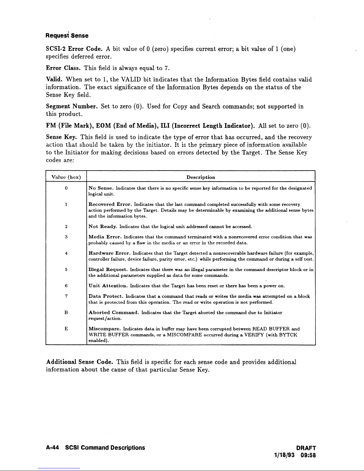
Request Sense
SCSI-2 Error Code. A bit value of 0 (zero) specifies current error;
a'bit
value
of'
1 (one)
specifies deferred error.
to
Error Class. This field is always equal
Valid. When set
information.
to
1, the
The
exact significance of
VALID
bit indicates
7.
that
the Information Bytes field contains valid
the
Information Bytes depends on
the
status
of
Sense Key field.
Segment Number.
Set to zero (0). Used for Copy and Search commands; not supported in
this product.
FM
(File Mark), EOM (End
Sense
action
to
Key. This field is used
that
should be taken by the initiator.
the Initiator for making decisions based on errors detected by the Target. The Sense Key
of
Media), ILl
to
indicate
(In~orred
the
type of error
It
is
the primary piece of information available
Length
that
Indi~ator).
All set
to
zero (0).
has occurred, and the recovery
codes are:
Value
(hex)
0
1
No
Sense.
logical
unit.
Recovered
action
performed
and
the
information
Indicates
Error.
by
that
there
Indicates
the
Target.
bytes.
is
that
Details
no
the
Description
specific sense key
last
command
may
be
completed
determinable
infonnation
successfully
by
examining
to
be
reported
with
some recovery
the
additional
for
the
designated
the
sense
bytes
Not
2
3
4
S
6
7
B
E
Ready.
Media
probably
Hardware
controller
Dlegal
the
additional
Unit
Data
that
is
Aborted
request
Miscompare.
WRITE
enabled).
Indicates
Error.
Indicates
caused
by
a flaw
Error.
failure, device failure,
Request.
Attention.
Protect.
protected
Command.
/ action.
BUFFER
Indicates
Indicates
parameters
Indicates
Indicates
from
Indicates
commands,
that
the
logical
that
the
in
the
media
that
parity
that
there
supplied
that
the
that a command
this
operation.
Indicates
data
in
or
that
buffer
a MIS
unit
command
or
the
Target
error,
was
as
data
Target
The
the
may
COMPARE
addressed
terminated
an
error
detected
etc.) while
an
illegal
for
some
has
been
that
reads
read
or
Target
have
cannot
with
in
the
recorded
a nonrecoverable
performing
parameter
commands.
reset
or
or'writes
write
operation
aborted
been
the
corrupted
occurred
be
accessed.
a nonrecovered
data.
the
in
the
there
has
the
media
is
not
command
between
during a VERIFY
error
hardware
command
command
been a power
was
performed.
due
to
READ
condition
failure (for
or
during
descriptor
on.
attempted
Initiator
BUFFER
(with
BYTCK
a self
block
on a block
and
Additional Sense Code. This field is specific for each sense code and provides additional
the
information about
cause of
that
particular Sense
Key.
that
was
example,
test.
or
in
A·44
SCSI
Command Descriptions
DRAFT
1/18/93 09:58
 Loading...