

Page 1

Combined Service
Manual
HP LaserJet 4 / 4M
(C2001A / C2021A)
HP LaserJet 4 Plus /
4M Plus
(C2037A / C2039A)
HP LaserJet 5 / 5M
/5N
(C3916A/C3917A/
C3952A)
Page 2

© Copyright
Hewlett-Packard
Company 1996
All Rights Reserved.
Reproduction, adaptation,
or translation without
prior written permission
is prohibited, except as
allowed under the
copyright laws.
Publication number
C3916-90984
First edition, March 1996
Printed in USA
Warranty
The information
contained in this
document is subject to
change without notice.
Hewlett-Packard makes
no warranty of any kind
with regard to this
material, including, but
not limited to, the
implied warranties or
merchantability and
fitness for a particular
purpose.
Hewlett-Packard shall
not be liable for errors
contained herein or for
incidental or
consequential damaged
in connection with the
furnishing, performance,
or use of this material.
WARNING
Electrical Shock
Hazard
To avoid electrical shock,
use only supplied power
cords and connect only to
properly grounded
(3-hole) wall outlets.
Hewlett-Packard Company
11311 Chinden Boulevard
Boise, Idaho 83714
Page 3

Conventions
This manual uses the following conventions:
Unless specifically stated otherwise, information applies to all
seven printer models (LaserJet 4/4 Plus/4 M/4 M Plus/5/5 M/5 N).
Most procedures are combined for all printers, except where they
differ substantially.
Color is used to emphasize items which are important to the
material under discussion.
The names of major printer parts and assemblies are Capitalized.
Bold is used for emphasis, particularly in situations where italic
type would be confusing.
Italic type is used to indicate related documents or emphasis.
COMPUTER type indicates text as seen on a computer monitor.
DISPLAY type indicates text as seen on the printer’s 16 character
LCD display panel (LaserJet 4Plus/4MPlus only).
[KEYFACE] indicates keys on a computer keyboard or on the
printer’s control panel. Examples include [Enter], [On Line] and
Go.
Note
CAUTION
WARNING!
Notes contain important information set off from
the text.
Caution messages alert you to the possibility of
damage to equipment or loss of data.
Warning messages alert you to the possibility of
personal injury.
i
Page 4

ii
Page 5

Contents
1 Product Information
Product Family Information . . . . . . . . . . . . . . . 1-2
Identification . . . . . . . . . . . . . . . . . . . . . . . 1-3
Specifications . . . . . . . . . . . . . . . . . . . . . . . . 1-5
HP LaserJet 4 and 4 Plus . . . . . . . . . . . . . . . . 1-5
Related Documentation . . . . . . . . . . . . . . . . . . 1-7
Safety Information . . . . . . . . . . . . . . . . . . . . . . 1-8
Product and Laser Safety . . . . . . . . . . . . . . . . 1-8
FCC RFI Statement . . . . . . . . . . . . . . . . . . . 1-9
Laser Statement (Sweden/Finland) . . . . . . . . . . 1-10
Toner Safety . . . . . . . . . . . . . . . . . . . . . 1-11
Ozone Statement . . . . . . . . . . . . . . . . . . . . 1-11
Doing Business with HP . . . . . . . . . . . . . . . . . . 1-12
Technical Assistance . . . . . . . . . . . . . . . . . 1-12
HP ASAP 1-800-333-1917 (U.S.) . . . . . . . . . . . . 1-12
HP FIRST . . . . . . . . . . . . . . . . . . . . . . . . 1-12
HP FIRST, U.S. . . . . . . . . . . . . . . . . . . . . . 1-12
HP FIRST, Europe . . . . . . . . . . . . . . . . . . . 1-12
HP AUDIO-TIPS . . . . . . . . . . . . . . . . . . . . 1-13
HP CompuServe Forum . . . . . . . . . . . . . . . . 1-13
Customer Information Centers . . . . . . . . . . . . . 1-13
Customer Support Center (Assist Line) . . . . . . . . 1-13
Printer Drivers . . . . . . . . . . . . . . . . . . . . . 1-13
European Customer Support Center . . . . . . . . . 1-14
Other Areas . . . . . . . . . . . . . . . . . . . . . . . 1-14
2 Site Planning and Requirements
Site Requirements . . . . . . . . . . . . . . . . . . . . . . 2-1
Printer Space Requirements . . . . . . . . . . . . . . . 2-2
Print Media Specifications . . . . . . . . . . . . . . . . 2-3
Adhesive Labels . . . . . . . . . . . . . . . . . . . . . 2-5
Label Construction . . . . . . . . . . . . . . . . . . . . 2-5
Overhead Transparencies . . . . . . . . . . . . . . . . 2-6
Envelopes . . . . . . . . . . . . . . . . . . . . . . . . . 2-6
Envelope Construction . . . . . . . . . . . . . . . . . . 2-7
3 Configuration
Introduction . . . . . . . . . . . . . . . . . . . . . . . . . 3-1
Using The Control Panel . . . . . . . . . . . . . . . . . . 3-2
Contents-1
Page 6

Control Panel Keys . . . . . . . . . . . . . . . . . . . 3-2
Reset Menu . . . . . . . . . . . . . . . . . . . . . . . 3-5
Control Panel Menus . . . . . . . . . . . . . . . . . . . 3-6
Printer Features . . . . . . . . . . . . . . . . . . . . . . 3-13
Page Protection (HP LaserJet 4 only) . . . . . . . . . 3-13
Resource Saving (HP LaserJet 4 Plus and 5 only) . . 3-14
I/O Buffering (HP LaserJet 4 Plus and 5 only) . . . . 3-15
EconoMode (HP LaserJet 4 Plus and 5 only) . . . . . 3-16
Resolution Enhancement (REt) . . . . . . . . . . . . 3-16
Memory Enhancement technology (MEt)
(HP LaserJet 4 Plus and 5 only) . . . . . . . . . . 3-17
Density . . . . . . . . . . . . . . . . . . . . . . . . 3-17
Network Security . . . . . . . . . . . . . . . . . . . . . 3-18
Remote Control Panel (DOS) . . . . . . . . . . . . . 3-18
HP LaserJet Utility (Macintosh) . . . . . . . . . . . 3-18
HP JetAdmin Utility (Novell Networks) . . . . . . . 3-19
Service Mode . . . . . . . . . . . . . . . . . . . . . . . 3-20
Setting the Page Count . . . . . . . . . . . . . . . . 3-21
Setting the Cold Reset Default . . . . . . . . . . . 3-22
Cold Reset . . . . . . . . . . . . . . . . . . . . . . . . 3-23
Understanding the PCL Self Test Printout . . . . . . 3-24
Changing the Control Panel Display Language . . . . 3-28
Test Print Button . . . . . . . . . . . . . . . . . . . . 3-29
System Configuration . . . . . . . . . . . . . . . . . 3-31
MS-DOS System Configuration . . . . . . . . . . . . 3-31
Parallel DOS Commands . . . . . . . . . . . . . . . 3-31
Serial MS-DOS Commands . . . . . . . . . . . . . . 3-32
Printer I/O Configuration . . . . . . . . . . . . . . . . . 3-33
Parallel Menu . . . . . . . . . . . . . . . . . . . . . 3-33
Advanced Functions . . . . . . . . . . . . . . . . . 3-33
Serial Configuration . . . . . . . . . . . . . . . . . . 3-33
Serial Protocol . . . . . . . . . . . . . . . . . . . . . 3-33
BAUD Rate . . . . . . . . . . . . . . . . . . . . . . . 3-33
Pacing (Handshaking) . . . . . . . . . . . . . . . 3-34
Serial Cable Pin-outs . . . . . . . . . . . . . . . . . . . 3-35
DB-9 RS-232 Serial Connection — HP LaserJet 4 . . 3-35
DB-25 RS-232 Serial Connection — HP LaserJet 4
Plus/5 . . . . . . . . . . . . . . . . . . . . . . . . . 3-36
DB-25 Serial Connection — HP LaserJet 4 . . . . . 3-37
DB-25 RS-232 Serial Connection — HP LaserJet 4
Plus/5 . . . . . . . . . . . . . . . . . . . . . . . . . 3-38
RS-422A Serial Connection (Not available on the
HP LaserJet 4 Plus or 5 printers) . . . . . . . . . 3-39
RS-422A Serial Configuration (LaserJet 4 only) . . . 3-39
Modular I/O Configuration . . . . . . . . . . . . . . . . 3-40
Contents-2
Page 7

Printer Drivers . . . . . . . . . . . . . . . . . . . . . . . 3-41
Install Printer Drivers and Utilities . . . . . . . . . 3-41
How to Obtain Printer Drivers . . . . . . . . . . . . . 3-41
DOS Utilities . . . . . . . . . . . . . . . . . . . . . . . . 3-42
Packing the Printer . . . . . . . . . . . . . . . . . . . 3-43
Repackaging Instructions . . . . . . . . . . . . . . 3-43
Packing Checklist . . . . . . . . . . . . . . . . . . . . 3-43
Installing The Optional Lower Cassette . . . . . . . . 3-44
Loading Paper into the Optional Lower Cassette . . 3-45
Envelope Feeder Installation . . . . . . . . . . . . . . . 3-49
LaserJet 4 and 4 Plus . . . . . . . . . . . . . . . . . . 3-50
LaserJet 5 . . . . . . . . . . . . . . . . . . . . . . . . 3-50
SIMM Installation . . . . . . . . . . . . . . . . . . . . . 3-51
Protecting the SIMM Board . . . . . . . . . . . . . . 3-51
Memory Requirements . . . . . . . . . . . . . . . . . 3-53
Accessing the SIMM Slots . . . . . . . . . . . . . . . 3-55
Installing the SIMM Boards . . . . . . . . . . . . . . 3-55
Testing a SIMM Board . . . . . . . . . . . . . . . . . . 3-57
Memory SIMM . . . . . . . . . . . . . . . . . . . . . 3-57
Running a Self Test Printout . . . . . . . . . . . . . . 3-57
Personality SIMM
(PostScript) . . . . . . . . . . . . . . . . . . . . . . 3-58
Troubleshooting a SIMM Board . . . . . . . . . . . . . . 3-59
Service / Error Messages . . . . . . . . . . . . . . . . 3-59
4 Preventive Maintenance
Introduction . . . . . . . . . . . . . . . . . . . . . . . . . 4-1
Life Expectancy of Consumables . . . . . . . . . . . . . . 4-2
Service Checkpoints . . . . . . . . . . . . . . . . . . . . . 4-3
Cleaning Your Printer . . . . . . . . . . . . . . . . . . 4-4
Toner Cartridge . . . . . . . . . . . . . . . . . . . . . . 4-5
Saving Toner with EconoMode (HP LaserJet 4
Plus and 5 Only) . . . . . . . . . . . . . . . . . . . . 4-6
Storing the Toner Cartridge . . . . . . . . . . . . . . . 4-6
Installing the Toner Cartridge . . . . . . . . . . . . . 4-7
Non-HP Toner Cartridges . . . . . . . . . . . . . . . . 4-9
Clearing the TONER LOW Message . . . . . . . . . 4-10
Periodic Maintenance Procedures . . . . . . . . . . . . 4-11
Removing the MP Tray (Tray 1) Pickup Roller and
Separation Pad . . . . . . . . . . . . . . . . . . . 4-11
Removing the PC (Tray 2) Pickup Roller . . . . . . 4-13
Removing the Lower Cassette (LC) or (Tray 3)
Pickup Roller . . . . . . . . . . . . . . . . . . . . 4-14
Removing and Replacing the Transfer Roller . . . . 4-15
Contents-3
Page 8

Removing the Transfer Roller . . . . . . . . . . . . 4-16
Replacing the Transfer Roller . . . . . . . . . . . . 4-16
5 Functional Overview
Introduction . . . . . . . . . . . . . . . . . . . . . . . . . 5-1
DC Controller System . . . . . . . . . . . . . . . . . . 5-2
DC Controller Loads . . . . . . . . . . . . . . . . . . . 5-3
Serial Data Communication . . . . . . . . . . . . . . . 5-4
Solenoids . . . . . . . . . . . . . . . . . . . . . . . . . 5-5
Photosensors . . . . . . . . . . . . . . . . . . . . . . . 5-6
Microswitches . . . . . . . . . . . . . . . . . . . . . . 5-8
PC (Tray 2) and LC (Tray 3) Tray Size Sensing
System . . . . . . . . . . . . . . . . . . . . . . . . . 5-9
Motors . . . . . . . . . . . . . . . . . . . . . . . . . 5-10
Paper Jam Detection . . . . . . . . . . . . . . . . . 5-11
Formatter System . . . . . . . . . . . . . . . . . . . . 5-12
I/O Control . . . . . . . . . . . . . . . . . . . . . . . 5-12
Memory Management . . . . . . . . . . . . . . . . . 5-14
Data Processing . . . . . . . . . . . . . . . . . . . . 5-14
PJL Overview . . . . . . . . . . . . . . . . . . . . . 5-15
Image Formation System . . . . . . . . . . . . . . . . . 5-16
Photosensitive Drum . . . . . . . . . . . . . . . . . 5-17
Drum Sensitivity . . . . . . . . . . . . . . . . . . . 5-17
Cleaning Stage . . . . . . . . . . . . . . . . . . . . 5-18
Conditioning Stage . . . . . . . . . . . . . . . . . . 5-19
Writing Stage . . . . . . . . . . . . . . . . . . . . . 5-20
Developing Stage . . . . . . . . . . . . . . . . . . . 5-22
Transferring Stage . . . . . . . . . . . . . . . . . . 5-24
Fusing Stage . . . . . . . . . . . . . . . . . . . . . 5-25
Paper Feed System . . . . . . . . . . . . . . . . . . . 5-26
Printing from the MP Tray (Tray 1) . . . . . . . . . 5-29
Printing from the PC Tray (Tray 2) . . . . . . . . . 5-30
Power System . . . . . . . . . . . . . . . . . . . . . . . 5-31
Basic Sequence of Operation . . . . . . . . . . . . . . 5-33
Standard Printer Operation . . . . . . . . . . . . . 5-33
Timing Diagrams . . . . . . . . . . . . . . . . . . . 5-34
Warmup Period . . . . . . . . . . . . . . . . . . . . 5-37
Standby Period . . . . . . . . . . . . . . . . . . . . 5-37
PowerSave . . . . . . . . . . . . . . . . . . . . . . . 5-37
Initial Rotation Period . . . . . . . . . . . . . . . . 5-38
Print Period . . . . . . . . . . . . . . . . . . . . . . 5-40
Last Rotation Period . . . . . . . . . . . . . . . . . . . 5-42
Contents-4
Page 9

6 Removal and Replacement
Required Tools . . . . . . . . . . . . . . . . . . . . . . . . 6-2
Hardware Review . . . . . . . . . . . . . . . . . . . . . . 6-2
Removing the Covers . . . . . . . . . . . . . . . . . . . . 6-4
Right Side Cover Removal . . . . . . . . . . . . . . . . 6-4
Top Cover Removal . . . . . . . . . . . . . . . . . . . 6-5
Left Side Cover Removal . . . . . . . . . . . . . . . . . 6-7
Rear Door Removal . . . . . . . . . . . . . . . . . . . . 6-8
Font Door Cover Removal (LJ 5 Right Front
Cover Removal) . . . . . . . . . . . . . . . . . . . 6-10
Multi-Purpose (MP) Tray (Tray 1) Door Removal . . . 6-12
Multi-Purpose (MP) Tray (Tray 1) Removal . . . . . . 6-13
Assemblies Removal . . . . . . . . . . . . . . . . . . . . 6-15
Power Supply Removal . . . . . . . . . . . . . . . . . 6-15
Paper Feed Assembly Removal . . . . . . . . . . . . . 6-18
High Voltage Power Supply (HVPS) Removal . . . . . 6-21
Fuser Assembly Removal . . . . . . . . . . . . . . . . 6-22
Control Panel and Overlay Removal . . . . . . . . . . 6-23
Removing the SIMMs Door . . . . . . . . . . . . . . 6-25
Formatter Cage Removal . . . . . . . . . . . . . . . . 6-27
Formatter PCA Removal . . . . . . . . . . . . . . . . 6-29
DC Controller Removal . . . . . . . . . . . . . . . . . 6-33
DC Controller Installation . . . . . . . . . . . . . . . 6-35
Main Motor Assembly Removal . . . . . . . . . . . . 6-37
Gear Assembly Removal . . . . . . . . . . . . . . . . 6-38
Fan Removal . . . . . . . . . . . . . . . . . . . . . . 6-39
Output Assembly Removal . . . . . . . . . . . . . . . 6-41
Paper Exit Sensor (PS3) Removal . . . . . . . . . . . 6-42
Scanner Assembly Removal . . . . . . . . . . . . . . 6-43
Lower Cassette Assemblies . . . . . . . . . . . . . . . . 6-44
Lower Cassette Sensor PCA Removal . . . . . . . . . 6-44
Lower Cassette Pickup Motor Removal . . . . . . . . 6-45
Replacing Fuser Assembly Parts . . . . . . . . . . 6-47
Fuser Assembly Configuration . . . . . . . . . . . . 6-48
Removing the Fuser Roller Heat Lamp . . . . . . . . 6-49
Fuser Assembly Thermoswitch Removal . . . . . . . 6-55
Thermistor Removal . . . . . . . . . . . . . . . . . . 6-56
Paper Control PCA Removal . . . . . . . . . . . . . . 6-59
Sensor PCA Removal . . . . . . . . . . . . . . . . . . 6-60
PS1 and PS2 Sensor Assembly Removal . . . . . . . 6-61
High Voltage Contact Plate (HVCP) and Paper Guide
Removal . . . . . . . . . . . . . . . . . . . . . . . . 6-62
Accessing the High Voltage Contact Plate and
Feed Guide Assembly . . . . . . . . . . . . . . . . 6-62
Contents-5
Page 10

Removing the High Voltage Contact Assembly and
Feed Guide Assembly . . . . . . . . . . . . . . . . 6-67
Replacing the High Voltage Contact
Assembly/Feed Guide Assembly . . . . . . . . . . 6-68
Interconnect PCA Removal . . . . . . . . . . . . . . . 6-69
7 Troubleshooting
LaserJet 5 Error Map . . . . . . . . . . . . . . . . . . . . 7-A
Pre-Troubleshooting Procedures . . . . . . . . . . . . . 7-1
Preliminary Operating Checks . . . . . . . . . . . . . 7-1
Printer Message Troubleshooting . . . . . . . . . . . 7-2
Printer Message Summary Table . . . . . . . . . . . 7-2
Clearable Warnings . . . . . . . . . . . . . . . . . 7-10
Printer Message Troubleshooting Procedures . . . . . . 7-12
Blank Display . . . . . . . . . . . . . . . . . . . . . 7-12
MP/PC/LC (Tray 1/2/3) LOAD Message . . . . . . 7-13
Cassette Size Switches (SW603, SW604, SW605)
Functional Check . . . . . . . . . . . . . . . . . . 7-15
Paper Size Sensing Lower Cassette . . . . . . . . . 7-16
PC Empty Sensor (PS2) Functional Check . . . . . . 7-17
PS4 Check (MP Tray Empty Sensor) . . . . . . . . . 7-17
12 Printer Open Message . . . . . . . . . . . . . . . 7-18
SW601 Functional Check . . . . . . . . . . . . . . . 7-19
13 PAPER JAM Message . . . . . . . . . . . . . . . 7-20
PS1 (Input/Registration Sensor) Check . . . . . . . . 7-22
PS3 (Exit Sensor) Check . . . . . . . . . . . . . . . . 7-23
Pickup Motor Functional Test (M2) . . . . . . . . . . 7-23
Lower Cassette Functional Check . . . . . . . . . . 7-24
14 NO EP CART Message . . . . . . . . . . . . . . . 7-25
16 Toner Low Message . . . . . . . . . . . . . . . . 7-25
41.X ERROR Message . . . . . . . . . . . . . . . . 7-27
50 SERVICE Error - Fuser Malfunction . . . . . . . 7-29
51 ERROR Message . . . . . . . . . . . . . . . . . . 7-31
52 ERROR Scanner Malfunction . . . . . . . . . . . 7-32
Laser/Scanner Assembly Functional Checks . . . . . 7-32
57 (or 57.1) SERVICE Message (Main Motor
Failure) . . . . . . . . . . . . . . . . . . . . . . . 7-33
Main Motor Functional Checks . . . . . . . . . . . . 7-33
58 (or 57.2) SERVICE (Fan Failure) . . . . . . . . . 7-34
Image Defect Summary . . . . . . . . . . . . . . . . . 7-35
PS5 Check (MP Tray Paper End Sensor)
Functional Test . . . . . . . . . . . . . . . . . . . 7-44
Image Formation Troubleshooting . . . . . . . . . . . . 7-49
Half Self-Test Functional Check . . . . . . . . . . . 7-49
Contents-6
Page 11

Drum Rotation Functional Check . . . . . . . . . . . 7-50
High Voltage Power Supply Assembly . . . . . . . . 7-51
Interface Troubleshooting . . . . . . . . . . . . . . . . . 7-52
Communications Check . . . . . . . . . . . . . . . . 7-52
Test Message . . . . . . . . . . . . . . . . . . . . . . 7-52
AUTOEXEC.BAT Standard Configurations . . . . . 7-53
Parallel DOS Commands . . . . . . . . . . . . . . . 7-53
Serial MS-DOS Commands . . . . . . . . . . . . . . 7-53
Communications Checks . . . . . . . . . . . . . . . . 7-54
MIO Troubleshooting . . . . . . . . . . . . . . . . . . . 7-56
Troubleshooting Hints . . . . . . . . . . . . . . . . . 7-56
Explanation of Self Test Printout . . . . . . . . . . . 7-57
Troubleshooting Aids . . . . . . . . . . . . . . . . . . . 7-59
Component Locations . . . . . . . . . . . . . . . . . . 7-59
Repetitive Defect Template . . . . . . . . . . . . . . 7-67
Voltage Test Points . . . . . . . . . . . . . . . . . . 7-69
Measuring the DC Voltage Levels . . . . . . . . . . . 7-69
8 Parts and Diagrams
How To Use the Parts Lists . . . . . . . . . . . . . . . . . 8-1
Parts Lists and Illustrations . . . . . . . . . . . . . . . 8-2
Accessory Parts . . . . . . . . . . . . . . . . . . . . . . 8-33
SIMM Memory . . . . . . . . . . . . . . . . . . . . . 8-38
Miscellaneous Parts and Accessories . . . . . . . . . 8-39
Parts List . . . . . . . . . . . . . . . . . . . . . . . . . . 8-40
A Duplexer
Functional Overview . . . . . . . . . . . . . . . . . . A-2
Duplex Printing . . . . . . . . . . . . . . . . . . . . . A-3
Switchback Assembly . . . . . . . . . . . . . . . . . . A-3
Holding Tray . . . . . . . . . . . . . . . . . . . . . . A-3
Electrical Overview . . . . . . . . . . . . . . . . . . . A-5
Installing the Optional Duplexer . . . . . . . . . . . . . A-6
Removal and Replacement . . . . . . . . . . . . . . . . A-8
Required Tools . . . . . . . . . . . . . . . . . . . . . A-8
Removing the Covers . . . . . . . . . . . . . . . . . . A-9
Removing the Switchback Covers . . . . . . . . . . . A-9
Removing the Side Cover on Power Side . . . . . . . A-10
Removing the Side Cover on Gear Side . . . . . . . . A-11
Removing the Back Cover . . . . . . . . . . . . . . . A-13
Removing the Front Cover . . . . . . . . . . . . . . . A-13
Removing Internal Duplexer Components . . . . . . . A-14
Removing the Fan/Motor/Solenoid/Sensor . . . . . . . A-14
Removing the Switchback Paper Guide . . . . . . . . A-15
Contents-7
Page 12

Removing the Paper Guide Assembly . . . . . . . . . A-16
Removing the Paper Roller . . . . . . . . . . . . . . A-17
Removing the Control PCA . . . . . . . . . . . . . . A-20
Removing the Power PCA . . . . . . . . . . . . . . . A-22
Removing the Holding Tray Center Paper Guide . . . A-23
Removing the Holding Tray Belt . . . . . . . . . . . A-24
Removing the Holding Tray Paper Sensor . . . . . . A-26
Removing the Switchback Assembly . . . . . . . . . A-27
Parts and Diagrams for the Duplexer . . . . . . . . . . A-28
B LaserJet 5/5M/5N Printer
Product Information . . . . . . . . . . . . . . . . . . . . . B-2
Product Family Information . . . . . . . . . . . . . . . B-3
Identification . . . . . . . . . . . . . . . . . . . . . . . . B-5
Specifications . . . . . . . . . . . . . . . . . . . . . . . . B-6
HP LaserJet 5 / 5M / 5N . . . . . . . . . . . . . . . . . B-6
Related Documentation . . . . . . . . . . . . . . . . . . B-8
Laser Statement (Sweden/Finland) . . . . . . . . . . B-9
Control Panel Layout . . . . . . . . . . . . . . . . . . . B-10
Control Panel Keys . . . . . . . . . . . . . . . . . . . B-10
Control Panel Menus . . . . . . . . . . . . . . . . . . B-13
To change a control panel setting: . . . . . . . . . . . B-13
Printing Menu . . . . . . . . . . . . . . . . . . . . . B-15
PCL Fonts Menu . . . . . . . . . . . . . . . . . . . . B-17
PostScript Menu . . . . . . . . . . . . . . . . . . . . B-18
Job Menu . . . . . . . . . . . . . . . . . . . . . . . . B-18
Configuration Menu . . . . . . . . . . . . . . . . . . B-19
Memory Configuration Menu . . . . . . . . . . . . . B-21
Parallel Menu . . . . . . . . . . . . . . . . . . . . . B-22
Serial Menu . . . . . . . . . . . . . . . . . . . . . . . B-22
Resets Menu . . . . . . . . . . . . . . . . . . . . . . B-23
Test Menu . . . . . . . . . . . . . . . . . . . . . . . B-24
Service Mode . . . . . . . . . . . . . . . . . . . . . . . B-25
Setting the Page Count . . . . . . . . . . . . . . . . B-26
Setting the Cold Reset Default . . . . . . . . . . . . B-27
Skip Demo . . . . . . . . . . . . . . . . . . . . . . . B-28
Big Data . . . . . . . . . . . . . . . . . . . . . . . . B-28
Diagnostics . . . . . . . . . . . . . . . . . . . . . . . B-28
Programming a Flash SIMM . . . . . . . . . . . . . . . B-29
Changing the Control Panel Display Language . . . B-30
NVRAM Init . . . . . . . . . . . . . . . . . . . . . . . . B-31
Understanding the PCL Self Test Printout . . . . . . . B-32
Infrared Communication . . . . . . . . . . . . . . . . . B-34
System Requirements . . . . . . . . . . . . . . . . . B-35
Contents-8
Page 13

To Print Using the Infrared Port . . . . . . . . . . . . B-36
Troubleshooting IR Printing Problems . . . . . . . . B-38
Infrared Port Not Responding . . . . . . . . . . . . . B-41
Contents-9
Page 14

Contents-10
Page 15
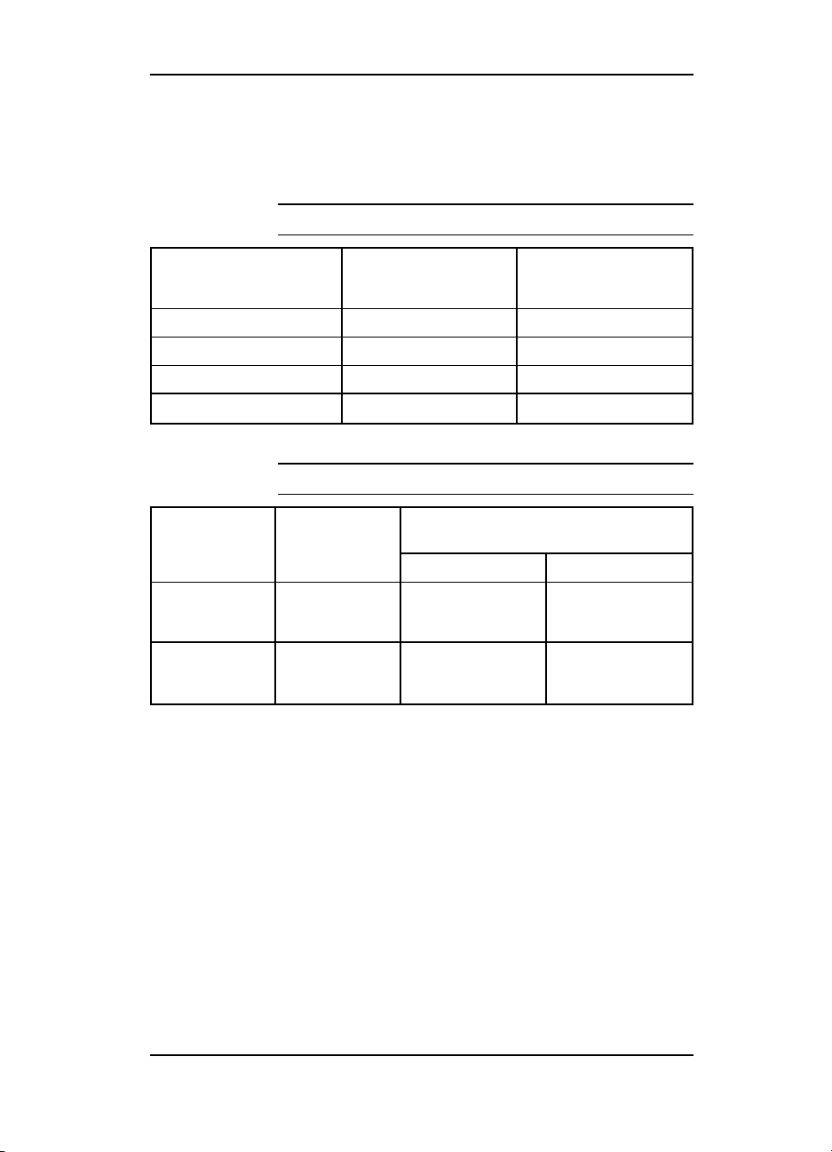
Product Information
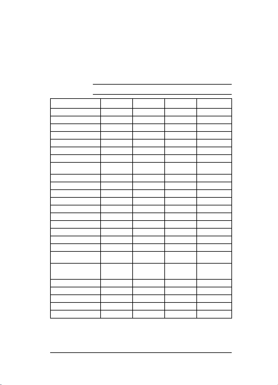
Table 1-1 Printer Features
Features HP LJ 4 HP LJ 4M HP LJ 4 Plus HP LJ4M Plus
Model C2001A C2021A C2037A C2039A
Printer Speed 8 ppm 8 ppm 12 ppm 12 ppm
Resolution 300/600 dpi 300/600 dpi 300/600 dpi 300/600 dpi
Expandable I/O Buffer No No Yes Yes
Resource Savings No No Yes Yes
MEt No No Yes Yes
REt Yes Yes Yes Yes
Languages Enhanced PCL5 Enhanced PCL5,
PostScript Upgradeable C2080A* N/ A C3129A* N/A
Resident Memory 2 MByte 6 MByte 2 MByte 6 MByte
Printer Max. Memory Capacity 34 MByte 26 MByte 66 MByte 50 MByte
Available Memory Slots Four Two** Four Two **
PC Tray Capacity 250 Sheets 250 Sheets 250 Sheets 250 Sheets
MP Tray Capacity 100 Sheets 100 Sheets 100 Sheets 100 Sheets
Output Capacity 250 Sheets 250 Sheets 250 Sheets 250 Sheets
500 Sheet Optional Feeder C2083A C2083A C2083D C2083D
Duplex Option N/A N/A C3157A C3157A
Envelope Feeder C2082A C2082A C2082B C2082B
Typefaces 45 PCL 45 PCL
Interfaces Serial (25 pin)
MIO Slots Yes Yes (J2341A) Yes Yes (J2552A)
EconoMode No No Yes Yes
Cartridge Slot Yes Yes Yes Yes
Power Sav e No No Yes Yes
Monthly Usage (pages) Up to 20,000 Up to 20,000 Up to 20,000 Up to 20,000
Parallel
Postscript Level 2
35 Postscript
Serial (25 pin)
Parallel, Local
Talk
Enhanced PCL5 Enhanced PCL5,
45 PCL 45 PCL
Serial (9 pin)
Parallel
Postscript Level 2
35 Postscript
Serial (9 pin)
Parallel
Local Talk
1
*The PostScript upgrade requires an additional 4 MB SIMM.
**PostScript & Memory SIMM already occupy 2 slots.
Product Information 1-1
Page 16
Product Family Information
The model HP C2021A is identical to the model HP C2001A from
a hardware standpoint, as is the model HP C2039A to the model
HP C2037A. The models HP C2021A and C2039A printers
include the following features:
• PostScript Level 2 SIMM
• AppleTalk MIO Card
• 4 MBytes of RAM
In every instance the repair procedures for all products are
similar.
Some LaserJet 4 accessories are compatible with the LaserJet 4
Plus and some are not. The compatibility chart below may be
used when there is a question of accessory compatibility.
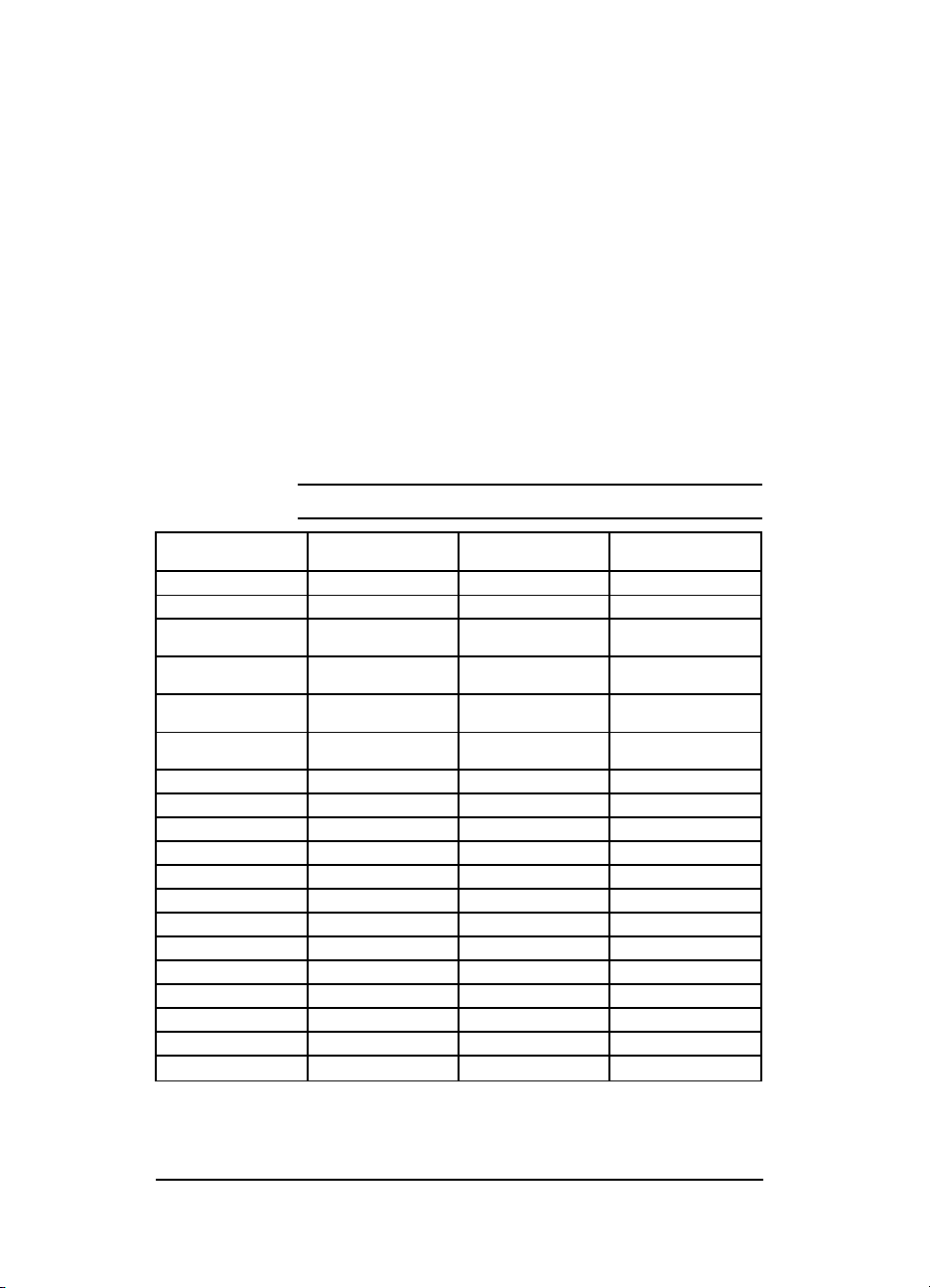
Table 1-2 Product Family Compatibility Matrix
Accessory Description Does it work in the
C2082A Envelope Feeder Yes No
C2082B Envelope Feeder Yes Yes
C2083A Optional 500 Sheet Feeder
C2083D Optional 500 Sheet Feeder
C2085A 250 Sheet Universal PC
C2085D 250 Sheet Universal PC
C3129A PostScript SIMM No Yes
C2080A PostScript SIMM Yes No
C2063A Memory (1 MByte) Yes Yes
C2064A Memory (2 MByte) Yes Yes
C2065A Memory (4 MByte) Yes Yes
C2066A Memory (8 MByte) Yes Yes
C3130A * Memory (1 MByte) No Yes
C3131A * Memory (2 MByte) No Yes
C3132A* Memory (4 MByte) No Yes
C3133A* Memory (8 MByte) No Yes
C3146A * Memory (16 MByte) No Yes
C3157A Duplex Assembly No Yes
92298A Toner Cartridge Yes Yes
*If HP LaserJet 4 Plus Optional Memory (C3130A, C3131A, C3132A, C3133 or C3146A) is installed in the HP
LaserJet 4, the printer will display a “53.1X.08 ERR O R” (X indicates the position of the SIMMs slot).
Assembly
Assembly
tray
tray
HPLaserJet 4?
Yes No
Yes Yes
Yes No
No Yes
Does it work in the
HPLaserJet 4 Plus?
1-2 Product Information
Page 17
Identification
The model number is on a label placed on the outside, rear cover
of the printer. The model number (C2001A, C2021A, C2037A or
C2039A) is found at the top of the label. The model number is the
base number for all printers.
The serial number contains information about the printer
Country of Origin. The serial number Alpha section refers to the
Country of Origin, the Revision Level and the Production Code.
The Numeric section refers to the production number of the
printer. See the following for information about the production
codes.
A typical serial number would consist of: CC R P XXXXXX
Code Meaning
CC Country of Origin
R Revision Number - Alphanumeric, no vowels
P Production Code - Alphanumeric, no vowels
XXX-XXXX Numeric serial number - Numeric, no alphas
C2037A
POWER R ATING:
100-120V 50-60 Hz, 7.8A
MANUFACTURED:
Made in Japan
XXX-XXXX
FCC ID: B94C2037A
Figure 1-1 Printer Identification Label for the
HP LaserJet 4 Plus/4M Plus
C2037A
Product Information 1-3
24131
TR1
Page 18
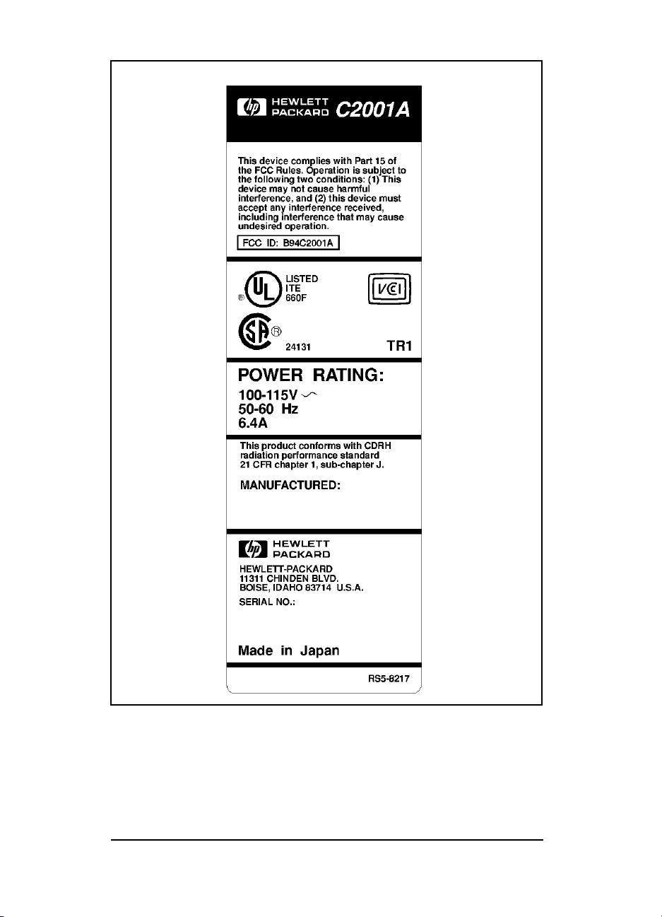
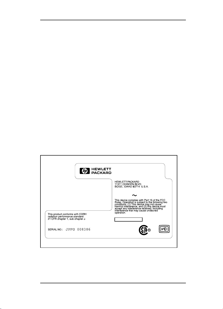
Figure 1-2 Printer Identification Label for the HP LaserJet
4/4M
1-4 Product Information
Page 19
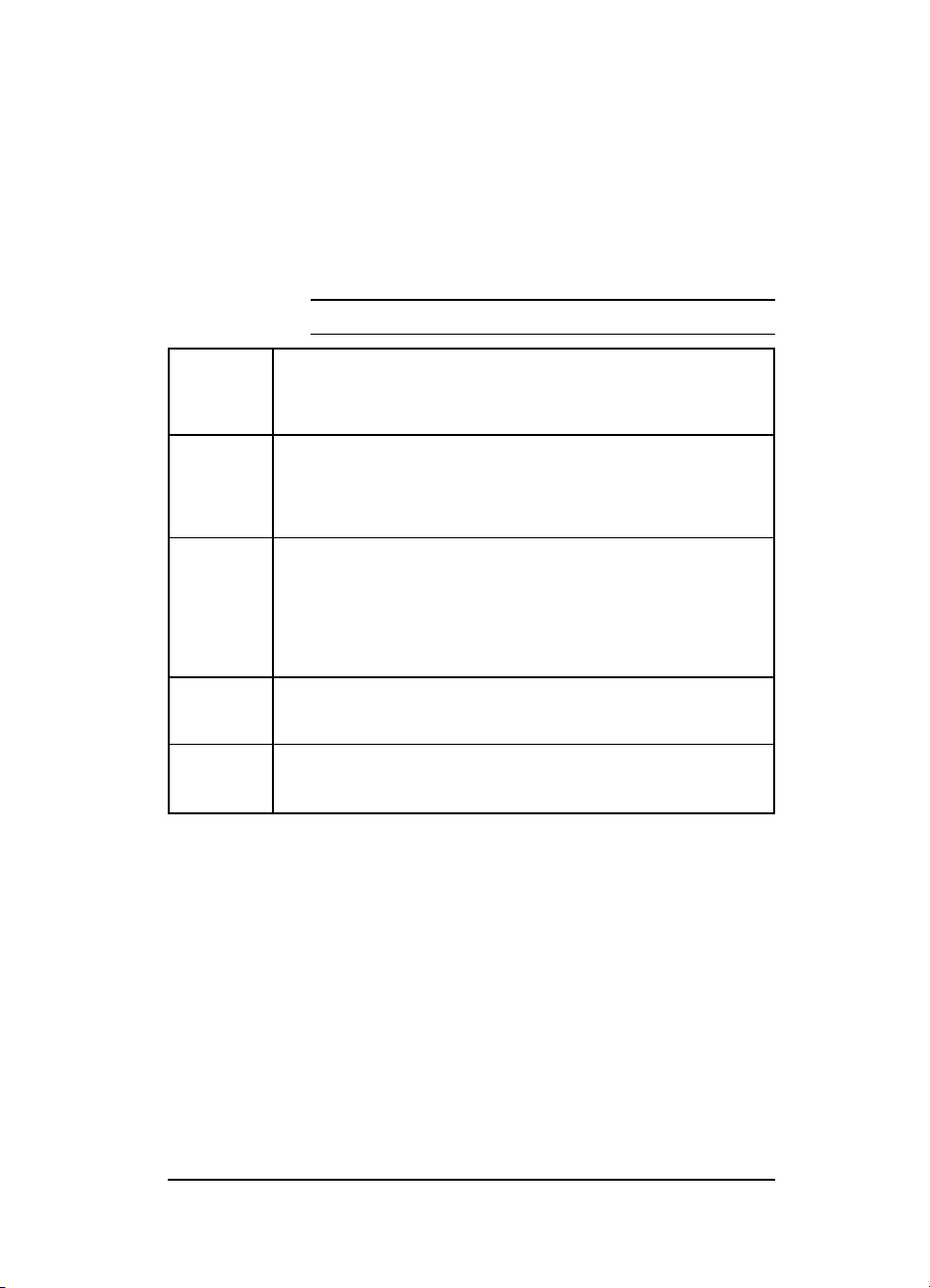
Specifications
HP LaserJet 4 and 4 Plus
Table 1-3 Printer Dimensions
Dimension HP LaserJet 4/4M
(C2001A/C2021A)
Width 16.4 in (416 mm) 16.4 in (416 mm)
Depth 15.9 in (403 mm) 15.9 in (403 mm)
Height 11.7 in (297 mm) 11.7 in (297 mm)
Weight (with toner cartridge) 37 lbs. (18.3 kg) 37 lbs. (18.3 kg)
HP LaserJet 4 Plus
HP LaserJet 4M Plus
(C2037A/C2039A)
Table 1-4 Power Specifications
Watts (typical)
Volts Freq 4/4M 4 Plus/4M Plus
100 Vac ± 10%
120 Vac ± 10%
220 Vac ± 10%
240Vac ± 10%
50/60 Hz ± 2 Hz
50/60 Hz ± 2 Hz
50/60 Hz ± 2 Hz
50/60 Hz ± 2 Hz
printing = 195
standby = 55
printing = 195
standby = 55
printing = 300
standby = 80
PowerSave=25
printing =300
standby = 80
PowerSave=25
Product Information 1-5
Page 20
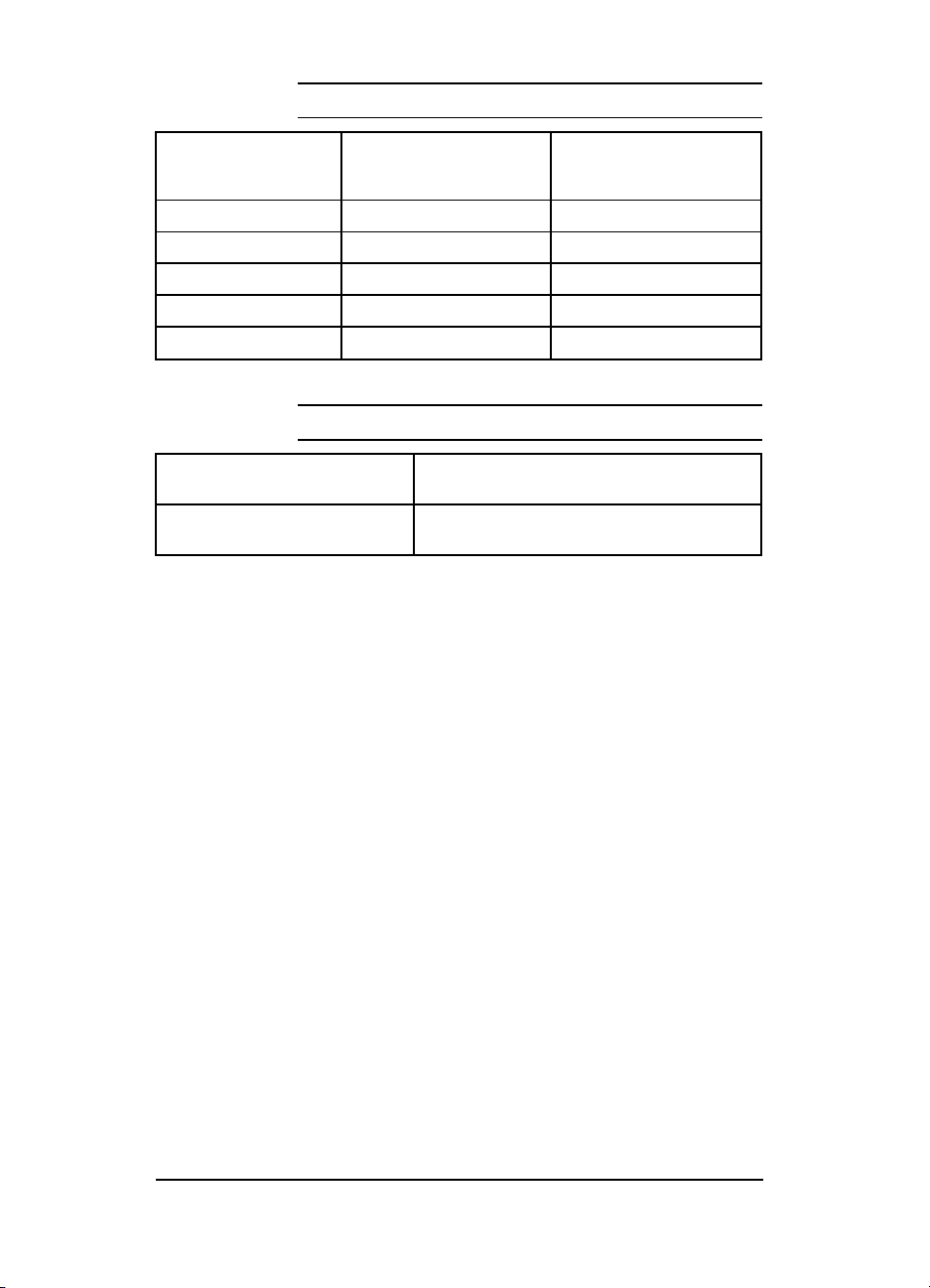
Table 1-6 Electrical Specifications
Status 100/115 V
4/4M 4 Plus/4M
Plus
Product Rating 6.4 amps 7.8 amps 3.1 amps 4.0 amps
Peak Inrush Current 22 amps 22 amps 22 amps 22 amps
25% Decay Time 13 msec 18 msec 11 msec 11 msec
Peak Fuser Current 38 amps 51 amps 17 amps 22 amps
Return-to Average Time 200 msec 200 msec 200 msec 200 msec
220/240 V
4/4M 4 Plus/4M
Plus
Table 1-5 Environmental Specifications
Operating Environment Temperature: 10° C to 32.5° C (50° F to 90.5° F)
Storage E nvironment
(not including toner cartridge)
Humidity: 20-80% (no condensation)
Temperature: -20° to 60° C (-4° to 140°F)
Humidity: 15-90% (no condensation)
1-6 Product Information
Page 21
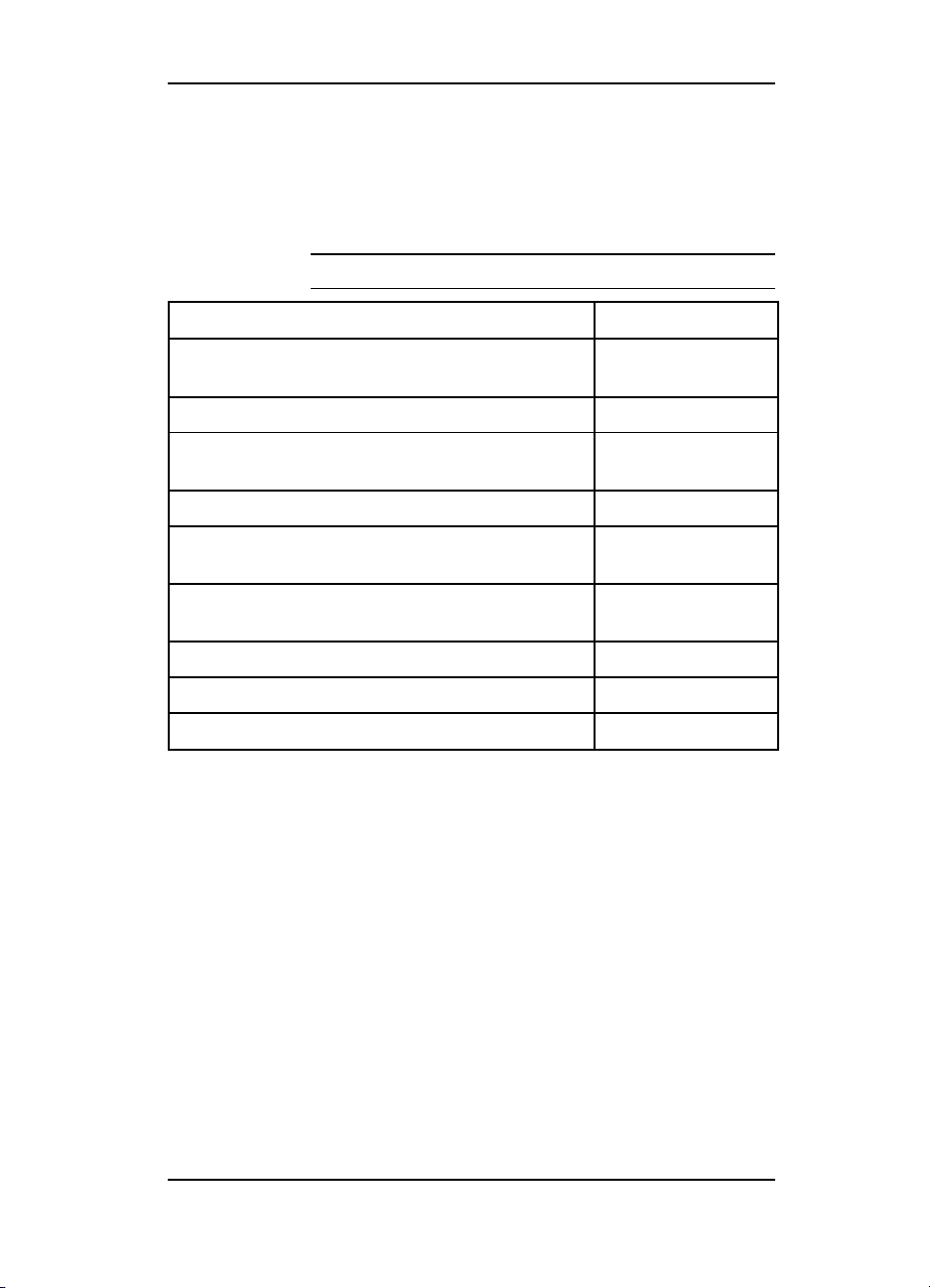
Related Documentation
The following manuals can be ordered from Hewlett-Packard’s
Support Materials Organization (SMO). The phone number for
SMO is (800) 227-8164.
Table 1-7
HP LaserJet 4 Documents—Description Part Number
Your Guide to Setting Up the HP LaserJet 4
Printer
HP LaserJet 4 User’s Manual C2001-90912
HP PCL5 Printer Language Technical
Reference Package
HPJet Direct Network Installation Guide J2552-90011
HPJet Direct Network Software Configuration
Guide
HP LaserJet 4 Plus and 4M Plus User’s Manual
HP LaserJet 4 Plus Getting Started Guide C2037-90917
HP LaserJet 4M Plus Getting Started Guide C2039-90901
Printer Documentation
C2001-90901
5010-3994
J2552-90001
HP LaserJet 4 Plus
Documents—Description Part Number
C2037-90901
Product Information 1-7
Page 22
Safety Information
Product and Laser Safety
HP printers are UL 1950 listed, CSA 22.2 950 certified, and
manufactured in accordance with DIN IEC 950. The printers are
certified as “Class 1” laser products under the U.S. Department of
Health and Human Services (DHHS) Radiation Performance
Standard, according to the Radiation Control for Health and
Safety Act of 1968. The printers do not produce hazardous laser
radiation.
Since radiation emitted inside the printer is completely confined
within protective housings and external covers, the laser beam
cannot escape during any phase of normal user operation.
The Center for Devices and Radiological Health (CDRH) of the
U.S. Food and Drug Administration implemented regulations for
laser products on August 2, 1976. These regulations apply to
laser products manufactured from August 1, 1976. Compliance is
mandatory for products marketed in the United States.
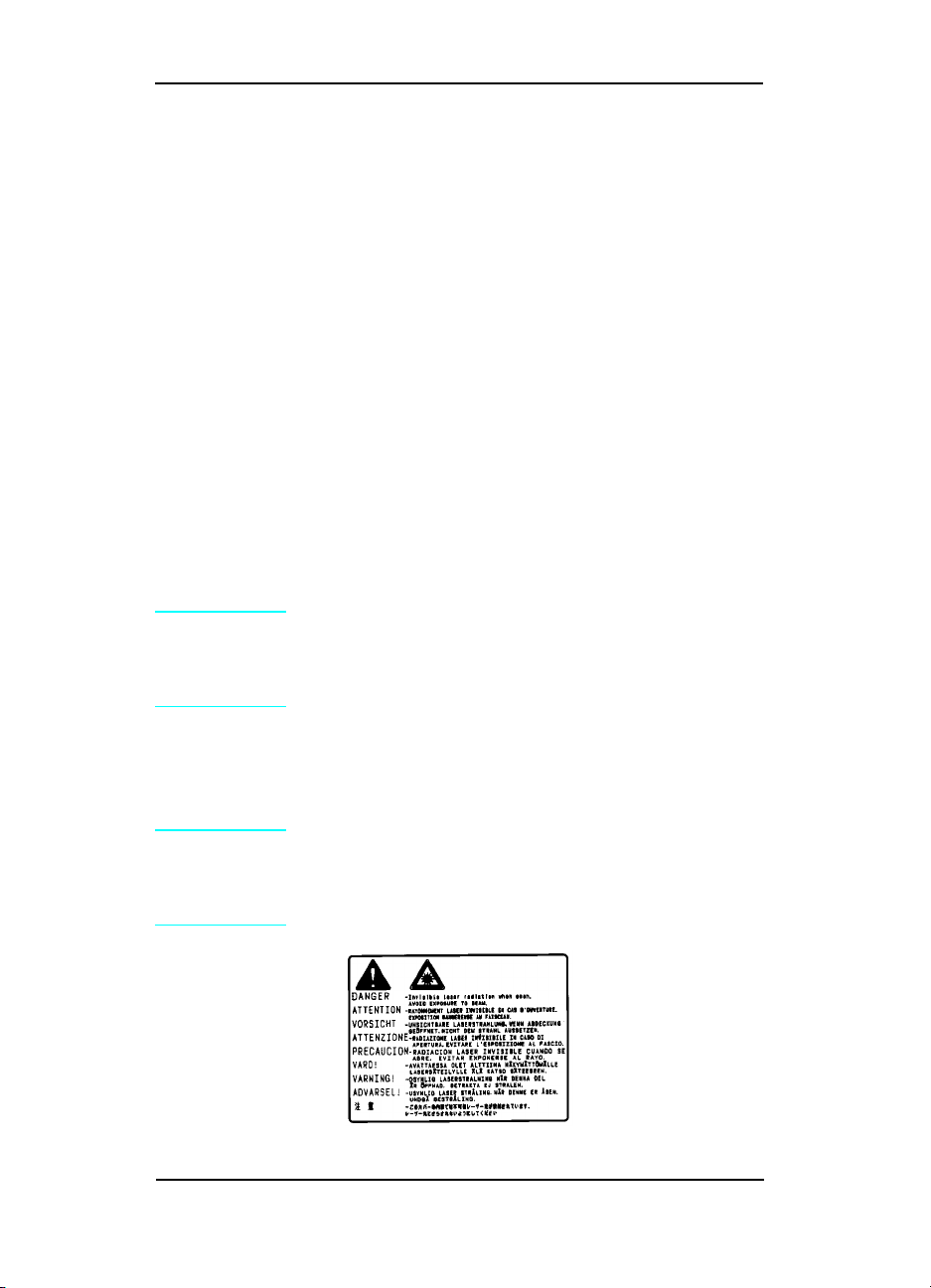
Note
Since the laser beam is invisible, the label on the following page
is attached to the Laser Scanner Cover inside the printer where
there is danger of exposure to laser radiation.
Caution
1-8 Product Information
In accordance with West German standard
VDE0836 (VDE-Bestimmung fur die Elektrische
Sicherheit von Lasergeraten und Anlagen), two
servicemen are required to service each unit.
Never service or operate the printer with the
protective cover removed from the laser scanner
assembly. The reflected beam, although invisible,
can damage your eyes.
Page 23

FCC RFI Statement
This equipment has been tested and found to comply with the
limits for a Class B digital device, pursuant to Part 15 of the FCC
Rules. These limits are designed to provide reasonable protection
against harmful interference when the equipment is operated in a
commercial environment. This equipment generates, uses, and
can radiate radio frequency energy and, if not installed and used
in accordance with the instruction manual, may cause harmful
interference to radio communications. However, there is no
guarantee that interference will not occur in a particular
installation. If this equipment does cause harmful interference to
radio or television reception, which can be determined by turning
the equipment off and on, the user is encouraged to try to correct
the interference by one or more of the following measures:
• Reorient or relocate the receiving attenna.
• Increase the separation between the equipment and the
receiver.
• Connect the equipment into an outlet on a circuit different
from that to which the receiver is connected.
• Consult the dealer or an experienced radio/TV technician for
help.
Any changes or modifications not expressly approved by
Hewlett-Packard could void the user’s authority to operate this
equipment.
Note
This product also meets the FCC Class A emission standards.
Use of a shielded interface cable is required to
comply with the Class B limits of Part 15 of the
FCC rules.
Product Information 1-9
Page 24

Laser Statement (Sweden/Finland)
LASERTURVALLISUUS
LUOKAN 1 LASERLAITE
KLASS 1 LASER APPARAT
HP LaserJet(s) 4/4M, 4 Plus/4M Plus laserkirjoitin on käyttäjän
kannalta turvallinen luokan 1 laserlaite. Normaalissa käytössä
kirjoittimen suojakotelointi estää lasersäteen pääsyn laitteen
ulkopuolelle.
Kirjoittimen on hyväksynyt Suomessa laserturvallisuuden osalta
Sähkötarkastuskeskus. Laitteen turvallisuusluokka on
määritetty valtioneuvoston päätöksen N:o 472/1985 ja standardin
EN 60825 (1991) mukaisesti.
VAROITUS ! Laitteen käyttäminen muulla kuin käyttöohjeessa
mainitulla tavalla saattaa altistaa käyttäjän turvallisuusluokan
1 ylittävälle näkymättömälle lasersäteilylle.
VARNING ! Om apparaten används på annat sätt än i
bruksanvisning specificerats, kan användaren utsättas för
osynlig laserstrålning, som överskrider gränsen för laserklass 1.
HUOLTO HP LaserJet (s) 4/4M, 4 Plus/4M Plus-kirjoittimen
sisällä ei ole käyttäjän huollettavissa olevia kohteita. Laitteen
saa avata ja huoltaa ainoastaan sen huoltamiseen koulutettu
henkilö. Tällaiseksi huoltotoimenpiteeksi ei katsota
väriainekasetin vaihtamista, paperiradan puhdistusta tai muita
käyttäjän käsikirjassa lueteltuja, käyttäjän tehtäväksi
tarkoitettuja ylläpitotoimia, jotka voidaan suorittaa ilman
erikoistyökaluja.
VARO !Mikäli kirjoittimen suojakotelo avataan, olet alttiina
näkymättömälle lasersäteilylle laitteen ollessa toiminnassa. Älä
katso säteeseen.
VARNING !Om laserprinterns skyddshölje öppnas då apparaten
är i funktion, utsättas användaren för osynlig laserstrålning.
Betrakta ej strålen.
Tiedot laitteessa käytettävän laserdiodin säteilyominaisuuksista:
Aallonpituus 770-795 nm
Teho 5 mW
Luokan 3B laser
1-10 Product Information
Page 25

Toner Safety
Note
A Material Safety Data Sheet (MSDS) for the toner cartridge
used in the HP printers, is available through Hewlett-Packard by
either mail or fax.
Mail. To obtain a MSDS for the 92298A LaserJet Toner Imaging
System through the mail, call the Customer Information Center
(CIC) at 1-800-752-0900 between 6 A.M. and 5 P.M. Pacific
Standard Time.
Fax. To obtain a MSDS for the 92298A LaserJet Toner Imaging
System by fax, call the HP FIRST number at (800) 333-1917 (U.S.
and Canada) and enter document number 1512.
Note
Toner may stain clothing. Skin and clothing are
best cleaned by removing as much toner as
possible with a dry tissue, then washing with cold
water. Hot water causes toner to melt and
permanently fuse into clothing.
To get documents from HP FIRST by fax, you
must use a Group 3 (touchtone) fax machine.
Ozone Statement
These printers do not use high voltage corona wires in the
electro-photographic process, and therefore generate no
measurable ozone gas (O
toner cartridge and a charging transfer roller in the printer.
). They use a charging roller in the
3
Product Information 1-11
Page 26

Doing Business with HP
Technical Assistance
HP ASAP 1-800-333-1917 (U.S.)
HP ASAP (Automated Support Access Program) provides free
technical support information 24 hours a day, 7 days a week. The
ASAP system includes HP FIRST and HP AUDIO-TIPS, both
explained below. The ASAP service requires a touch-tone phone.
HP FIRST
HP FIRST (Fax Information Retrieval Support Technology) is a
phone-in fax service providing technical information for HP
LaserJet users as well as service personnel. Receiving a fax
requires a group 3 facsimile machine or fax card. Service-related
information includes:
•
Service notes (HP Authorized Dealers) (password = 737842).
• Application notes.
• Product Data Sheets.
• Material Safety Data Sheets (MSDS).
• Typeface and accessory information.
• Printer support software information.
• Toner information.
• Driver request form and Software Matrix.
HP FIRST, U.S.
Call the HP ASAP system (1-800-333-1917) and follow the voice
prompts to enter HP FIRST.
HP FIRST, Europe
Call HP FIRST at one of the following numbers:
U.K., 0-800-96-02-71 Netherlands, 06-02-22-420
Belgium (Dutch), 0800-1-1906 Germany, 0130-8100-61
Switzerland (German), 155-1527 Austria, 0660-8128
For English service outside the above countries, (31) 20-681-5792
1-12 Product Information
Page 27

HP AUDIO-TIPS
HP AUDIO-TIPS, available within HP ASAP, is an interactive
voice response system providing pre-recorded answers to the
questions most frequently asked by HP LaserJet printer users.
Helpful “System Maps” to the HP AUDIO-TIPS recordings are
available by fax through HP FIRST.
HP CompuServe Forum
CompuServe members can download a variety of support
materials including product data sheets, software application
notes, and printer drivers for many popular software
applications. Members may also post and reply to questions in an
interactive format. To access the HP Forum, type GO HPPER at
any prompt. For more information, or to join CompuServe, call
1-800-524-3388.
Customer Information Centers
For further technical assistance, service-authorized HP and
dealer service personnel can contact the nearest Hewlett-Packard
Customer Information Center, 1-800-752-0900 in North America.
Customer Support Center (Assist Line)
The HP Customer Support Center, (208-323-2551) is available to
answer technical questions regarding setup, configuration,
installation and operation of HP printers in the PC and
Macintosh environments. The CSC Assist Line is available
weekdays from 7 am to 6 pm Mountain Time (Wednesdays until
4 pm).
Questions relating to operating systems such as MS-DOS and
UNIX, your network configuration, or network operating system
cannot be answered by the Center and should be referred to your
authorized reseller.
Printer Drivers
To order additional drivers for your software applications, call the
HP Driver Distribution Center at 1-970-339-7009.
Product Information 1-13
Page 28

European Customer Support Center
The HP European Customer Support Center, located in
Amsterdam, Holland, is open from 8:30 am to 6:00 pm central
European time (Wednesdays until 4:00 pm). Multilingual
customer support representatives can answer technical questions
similar to the U.S. CSC, described on the previous page. This
service is available at no charge for a period equivalent to the
original HP hardware warranty period.
Each time you call the HP European Customer Support Center,
you will be required to provide the printer’s serial number and
original date of purchase.
To receive a fax listing the supported languages on a country’s
phone number, call HP FIRST (refer to “HP FIRST,” earlier in
this section). You can also call the nearest HP Sales and Service
office to obtain the telephone number for the Center. The Center
features automated call-routing technology, so you will receive
faster service if calling from a touchtone phone or tone dialer.
Other Areas
Outside of North America and Europe, contact your local HP
sales office for assistance in obtaining technical support.
1-14 Product Information
Page 29

Site Planning and
Requirements
Site Requirements
The environmental specifications, listed in the Specifications
section of Chapter 1, must be maintained to ensure the proper
operation of this printer. Consider the following points before
installing the printer:
• Install the printer in a well-ventilated area.
• Install the printer on a sturdy, level surface.
• Install the printer where the temperature and humidity do not
change abruptly. Do not position the printer near water
sources, humidifiers, air conditioners, refrigerators, or other
major appliances.
• Do not expose the printer to direct sunlight, dust, open flames,
or ammonia fumes. If the printer is placed near a window,
make sure the window has a curtain or blind to block direct
sunlight.
• Install the printer away from walls. There must be enough
space around the printer for proper access and operation (see
Figure 2-1).
2
Site Planning and Requirements 2-1
Page 30
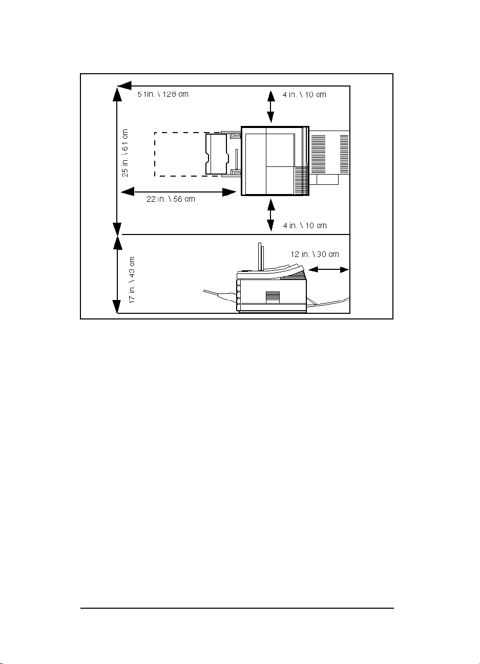
Printer Space Requirements
Figure 2-1 Space Requirements
2-2 Site Planning and Requirements
Page 31

Print Media Specifications
The complete media specifications are listed in the HP LaserJet
Family Paper Specifications Guide (part no. 5961-0920), that
came with this manual.
Each tray has its own set of paper specifications. Do not use
paper heavier than 36 pound from the MP tray (Tray 1), 28 pound
from the PC tray (Tray 2), or 24 pound from the LC Tray (Tray 3).
Table 2-1 Media Specifications for MP Tray (Tray 1)
Media Siz e C apacity Weight/Thickness Range
Paper Letter, Legal,
Executive, A4
Envelopes COM10,
MONARCH,
ISO DL, C5, B5
Transparencies Letter, A4 Approx. 75 0.0039 in. to 0.0045 in.
Labels Letter, A4 Approx. 75 0.005 in. to 0.007 in. thickness
Minimum Size: 3.5 in. x 6.5 in. (90 mm x 160 mm)
Maximum Size: 8.5 in. x 14 in. (216 mm x 356 mm)
100 sheets at
20# (75 g/m
10 of any kind 16# to 24# (60 to 90 g/m
16# to 36# (60 to 135 g/m
2
)
thickness (0.099 to 0.114 mm)
(0.127 to 0.178 mm)
2
)
2
)
Table 2-2 Media Specifications for PC Tray (Tray 2)
Media Size Capa city Weight/Thickness Range
Paper Letter, A4 250 sheets at
20# (75 g/m
16# to 28# (60 to 105 g/m
2
)
Site Planning and Requirements 2-3
2
)
Page 32

Table 2-3 Media Specifications for Optional LC Tray (Tray 3)
Media Size Capacity Weight/Thickness Range
Paper Letter, A4, Executive 500 sheets at 20#
(75 g/m
2
)
16# to 24# (60 to 90 g/m
2
)
Note Printing heavy paper stock (greater than 24 lb.
(90 g/m
2
) from the 500-sheet Lower Cassette
specifically is not supported.
Table 2-4 Media Specifications for Duplex Assembly (HP
LaserJet 4 Plus, 4M Plus, 5, 5M, and 5N pr inters)
Media Size Weight/Thickness Range
Paper Letter, Legal, A4 16# to 24# (60 to 90 g/m
2
)
2-4 Site Planning and Requirements
Page 33

Adhesive Labels
Note
Label Construction
When selecting labels, consider the quality of each component:
Printing labels using the Duplex Assembly , the
500-sheet Lower Cassette (Tray 3) or the PC tray
(Tray 2) specifically is not supported. Always use
the MP tray (Tray 1) to print labels.
• Adhesives: The adhesive material should be stable at the
392° F (200° C) temperatures encountered in the printer’s
fusing process. None of the adhesive should be exposed
between the labels.
•
Label arrangement: If possible, use labels with no exposed
areas between labels. If labels with exposed areas are used,
they should be arranged on the carrier sheet (the backing) so
that they cover the entire page with the exposed areas of the
carrier sheet running lengthwise down the sheet. Using label
stock with spaces between labels often results in labels peeling
off during the printing cycle, causing serious jamming
problems.
• Label curl: Labels must lie flat with no more than
0.5in(13mm) of curl in any direction.
• Poorly manufactured labels: Do not use labels with
wrinkles, bubbles, or other indications of delamination.
Site Planning and Requirements 2-5
Page 34

Overhead Transparencies
Note
Overhead transparencies used in HP LaserJet printers must be
able to withstand the 392° F (200° C) temperature encountered in
the printer’s fusing process. See the HP LaserJet Family Paper
Specifications Guide for more information.
Caution
Printing overhead transparencies using the
Duplex Assembly, the 500-sheet Lower Cassette
(Tray 3) or PC tray (Tray 2) specifically is not
supported.
Use only overhead transparencies recommended
for use in laser printers.
Envelopes
Many kinds of envelopes can be printed with your printer. Some
envelope styles perform better than others because their
construction is better suited to feeding through a laser printer.
Hewlett-Packard Company neither warrants nor recommends the
use of a particular brand of envelope. Envelope properties are
subject to change by envelope manufacturers, and
Hewlett-Packard Company has no control over such changes.
2-6 Site Planning and Requirements
Page 35

Envelope Construction
The following table lists the kinds of envelopes you can print in
the MP Tray (Tray 1).
Table 2-5 Specifications for Envelopes
Item Specifications
Minimum envelope size 3.5 in x 7 in (86 mm x 178 mm)
Maximum envelope size 7.4 in x 10.5 in (188 mm x 267 mm)
Basis Weight 16 to 24 pound (60 to 90 g/m2)
Quantity Maximum 10 envelopes
Envelope Size Dimensions
Commercial #10 (COM 10) 4.1 in x 9.5 in (105 mm x 241 mm)
#7 3/4 (Monarch) 3.8 in x 7.5 in (98 mm x 191 mm)
DL 109 mm x 218 mm (4.3 in x 8.6 in)
C5 163 mm x 231 mm (6.4 in x 9.1 in)
B5 178 mm x 251 mm (7.0 in x 9.9 in)
See the HP LaserJet Family Paper Specifications Guide for more
information.
Site Planning and Requirements 2-7
Page 36

2-8 Site Planning and Requirements
Page 37

3
Configuration
Introduction
The Configuration of the printer consists of setting hard and soft
user defaults, and setting up the host computer to communicate
with the printer (System Configuration). For installation
instructions refer to Installation in the Getting Started Manual
that is shipped with the printer.
Hard defaults are the I/O Menu and Configuration Menu
settings. These are set when the printer is installed and remain
as configured. The soft defaults (Printing menu and PCL menu)
change with the print job requirements. System Configuration
includes installing printer drivers, MODE commands and
updating the AUTOEXEC.BAT file.
The instructions in this chapter explain how to access the printer
features through the control panel, and how to set up the printer
in different configurations. This chapter explains how to check
the configuration settings, and how to verify that a configuration
is correctly selected.
Setup and configuration information for accessories is available
in this chapter. This information is intended to augment and not
replace the information provided with the accessories themselves.
If possible, use the information provided with the accessories
when installing the accessory products.
Use the information that comes with the printer drivers when
installing the printer. Many features of the printer are not
available without the correct printer driver for the software
application.
Configuration 3-1
Page 38

Using The Control Panel
(See Appendix B for LaserJet 5 information.)
Figure 3-1 Control Panel Keys
The control panel (see Figure 3-1) consists of eight keys, three
indicator lights, and a 16-character display panel. The three
indicator lights are described in Table 3-1.
Control Panel Keys
There are two rows of control panel keys. The upper row keys
have one function each. The lower row keys have a second level of
functions which are accessed by holding down [Shift]. Note that
the alternate functions [Reset], [Continue], and [-] are coded the
same color as [Shift]. Table 3-2 details both plain key functions
and shift-key combinations.
3-2 Configuration
Page 39
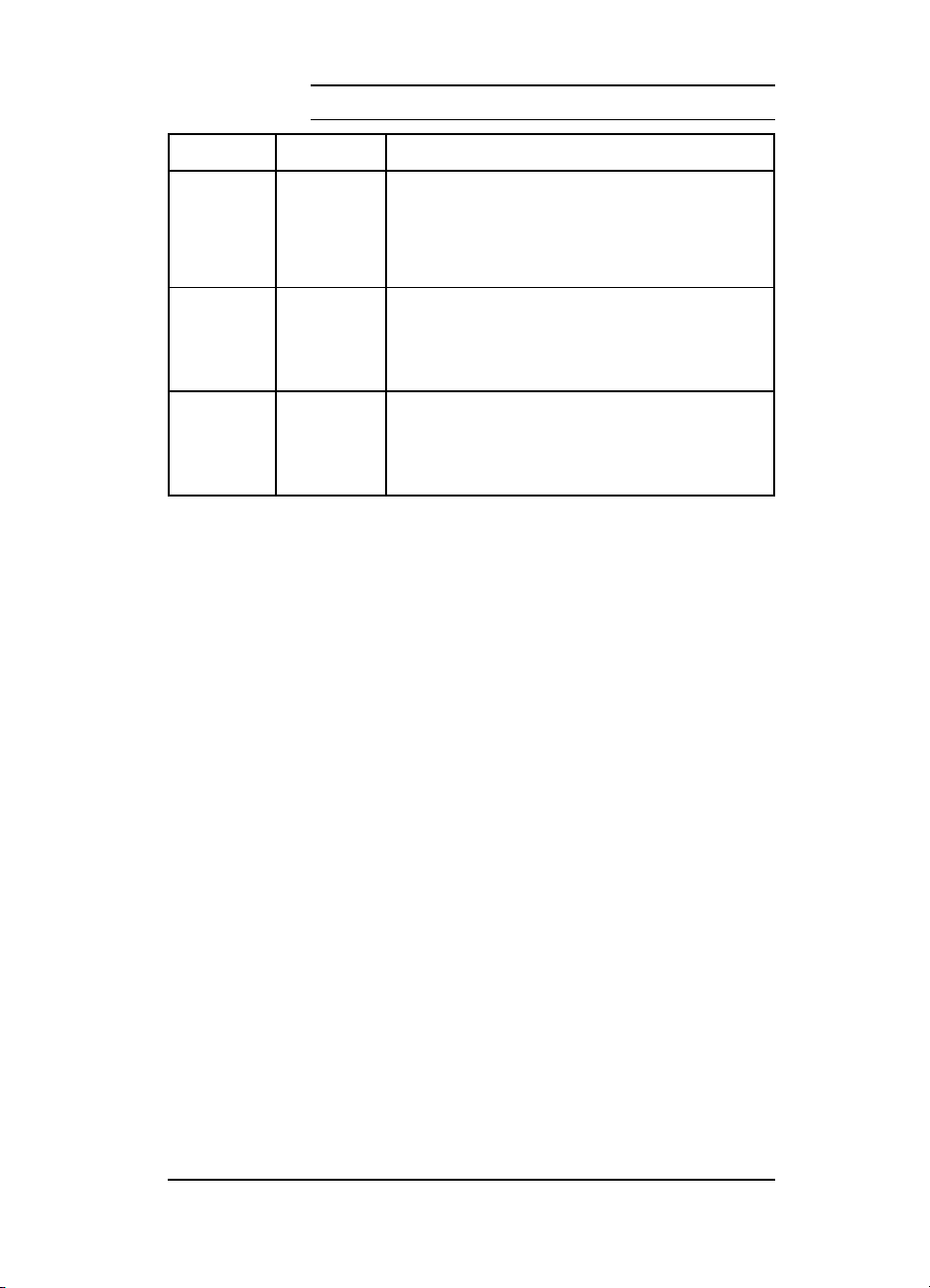
Table 3-1
Indicator Lights
Indicator Mode Description
Ready On: Ready to print.
Flashing: Processing a print job. Do not tak e off line or switch
Off: Not ready; see display for message.
On Line On: Ready to receive data.
Flashing: Going from on line to off line.
Off: Off line. Other keys can be accessed.
Form Feed On: Data still in printer buffer.
Flashing: Buffered data being printed.
Off: No buffered data in printer.
off.
Configuration 3-3
Page 40

Table 3-2
Control Panel Key Functions
Key Function
[On Line] Switches the printer between ON LINE (communicating with the
[Form Feed] Prints any data remaining in printer’s buffer. It cannot be used to send
[MP Paper
Size]
[Enter] Saves a selection in the printer’s “permanent” memory. An asterisk (*)
[Shift] Accesses the lower labels ( [Reset], [Continue], and [-]) on the control
[Menu] [Menu] cycles through the menu selections, returning to 00 READY at
[Continue] Continue ([Shift] + [Item]) allows the printer to resume printing after it
[+] or -] [+] or [-] allows you to step (by momentarily pressing the key) or scroll
computer or other data source) and OFF LINE (not communicating).
For the printer to receive data, both the On Line and Ready indicator
lights must be on.
a blank sheet of paper through the printer.
Selects the physical paper size loaded in the MP tray only when it is
operating as a PC tray.
appears next to the item to indicate that it is now the default. The
selection remains even if the printer is switched off or you perform a
reset.
If buffered data or temporary data (such as temporary downloaded
typefaces) are present, [Enter] only marks the items with an asterisk
(*) as the default. When you press [On Line] or [Menu], the message
10 RESET TO SAVE appears. There are three choices:
[Reset] Clears page buffers
RESET MENU (See the following table.) Clears page buffers
[On Line] Places the printer on line without performing a
reset.
panel. It works like the [Shift] key on your computer’s keyboard.
the end of the cycle unless an error, warning, or configuration
problem is encountered. If an option such as PostScript or a different
I/O has been added, that menu appears in the menu sequence.
has been placed off line due to an error condition or a device
attendance request (such as 21 PRINT OVERRUN). The [Continue] key
clears most error messages and places the printer back on line. It
functions like the [On Line] key except:
1. Continue does not override an error condition.
2. Continue allows you to override the paper or envelope siz e
selection regardless of what size media is in the MP tray.
3. Continue allows you to override a request to manually feed paper or
an envelope; it will selec t paper from the next available source instead.
(by holding down the key) through the item choices for a specific
menu. [Shift] [+] (or [-]) allows you to cycle through the item choices in
reverse order.
3-4 Configuration
Page 41
Reset Menu
Use Reset Menu function with caution. It can result in loss of
buffered page data or printer configuration data. Reset Menu is
activated by holding down both [Shift] and [Menu] for up to 10
seconds until RESET=MENU* appears. Use [+] or [-] to cycle through
items and [Enter] to select the item. The reset is executed by
pressing [On Line].
Table 3-2 Reset Menu Functions
[Reset]
(and Menu
of Resets)
The three
RESET=
choices are:
* indicates factory default.
A reset ([Shift] + [Menu]) displays a 07 RESET, clears the printer’s
page buffer, removes all temporary typefaces and macros, and makes
the current user-established defaults “permanent.” They will be the
default values until they are changed by the user.
To access the Menu of Resets, hold down both [Shift] and [Menu] for
about 10 seconds until RESET=MENU* appears in the display panel.
Use [-] to cycle through the display choices, and [Enter] to select the
option. Execute the reset by pressing [On Line]. The printer responds
with a reset message for the choice selected.
MENU* clears the page buffer, removes all temporary personality data
such as downloaded typefaces, and resets all printing environment
parameters (such as number of copies, paper size, etc.), and sets
user-selected defaults (such as MP tray default configuration) to their
factory defaults. Certain items, such as the display language or I/O
configuration, are not reset. RESET=MENU clears only the active I/O
input buffer.
ACTIVE I/O clears the page buffer, removes all perishable personality
data such as temporary typefaces, and clears the input and output
buffers for the active I/O only.
ALL I/O clears the page buffer, removes all perishable personality
data such as temporary typefaces, and clears the input and output
buffers for all I/Os.
Configuration 3-5
Page 42

Control Panel Menus
Figure 3-2 shows the menus and menu items available with the
basic printer configuration. Not all menu items are discussed in
this section. Only those items of specific interest from a service
standpoint, or items new to the printers are discussed in this
section. If options such as PostScript or a different I/O are
installed, new menu items automatically are added at the
appropriate location. For example, a PostScript Menu appears
following the PCL Menu.
3-6 Configuration
Page 43

Figure 3-2 Control Panel Map
Configuration 3-7
Page 44

Table 3-3 Printer Menu Items
Item Options Explanation
COPIES 1* to 999 Select any number from 1 to
PAPER
LETTER* (110V printers),
LEGAL, A4* (220V printers)
EXEC
999.
Sets default image si ze,
unless software setting
overrides it.
ENVELOPES
ORIENTATION P*, L P means portrait (vertical)
FORM
(5 to 128 lines)
MANUAL FEED OFF*, ON Only for MP Tray.
RET OFF, LIGHT, MEDIUM*, DARK Refines print quality.
ECONOMODE
(HP LJ4+only)
DUPLEX
(HP LJ4+ with
Duplex only)
BIND
(HP LJ4+with
Duplex only)
*indicates factory default.
COM10* (110V printers),
MONARCH, DL* (220V printers),
C5, B5
and L means landscape
(horizontal) orientation.
60* (110V printers)
64* (220V printers)
OFF*, ON Reduces amount of toner
OFF*, ON Allows for printing on both
LONG EDGE*
SHORT EDGE
Sets vertical spacing from 5
to 28 lines.
used.
sides of paper.
Determines orientation of
page.
3-8 Configuration
Page 45
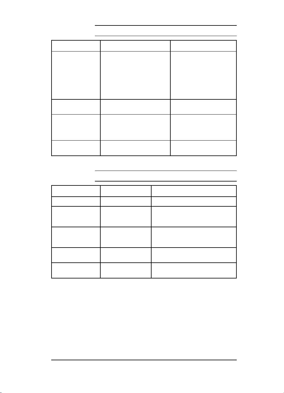
Table 3-3 PCL Menu Items
Item Options Explanation
FONT SOURCE I*
FONT NUMBER 0* to 999 Number assigned to each
PITCH
or
PT. SIZE
SYM SET ROMAN-8
*indicates factory default.
C
S
Mn (1-4)
Pitch:
10.00*
Point:
12.00*
Many others
Internal fonts*
Cartridge fonts
Permanent soft fonts
SIMM Module: n=slot
number. Typefaces stored in
one of the four ROM SIMM
slots (M1=slot 1, for
example).
typeface.
Depends on the FONT
SOURCE and FONT NUMBER
selected.
A unique grouping of all
characters in a font.
Table 3-4 Job Menu Items
Item Options Explanation
RESOLUTION 300 or 600* Sets the resolution.
PERSONALTY AUTO*
PWRSAVE
(HP LJ4+ only)
IO TIMEOUT 15*
PAGE PROTECT
(HP LJ4 only)
*indicates factory default.
PCL
PS (Postscript)
OFF, 15 MIN, 30
MIN,
1 HR, 2 HRS, 3 HRS
(5 to 300)
AUTO*, ON Only seen with error 21 PRINT
Sets the printer language.
Sets the amount of time the printer is
idle before the fuser shuts down.
Time in seconds that the printer waits
before ending a print job.
OVERRUN.
Configuration 3-9
Page 46
Table 3-5 Configuration Menu Items
Item Options Explanation
MP TRAY FIRST*
Paper is selected first.
CASS
MANUAL
LOCK NONE*
MP
PC
LC
and combinations
CLR WARN ON*, JOB Indicates a transient condition.
AUTO CONT OFF*
ON
DENSITY 1, 2, 3*, 4, 5 Determines relative darkness of print.
LOW TONER CONT*
STOP
*indicates factory default.
Operates as a PC tray.
Operates as a manual feed tray.
No trays are locked out.
The MP tray is locked out.
The PC tray is locked out.
The optional Lower Cassette is locked
out.
When an error is encountered, printer
goes off line until [SHIFT] + [CONTINUE]
are pressed.
When an error is encountered, printer
goes off line for 10 secs., then comes
back on line.
Higher numbers yield darker print but
shorter toner cartridge life. May take up
to 20 pages for new setting to stabilize.
Printer remains on line and continues to
print after the 16 TONER LOW message
is displayed.
Printer goes off line after the 16 TONER
LOW message is displayed.
3-10 Configuration
Page 47
Table 3-6
Memory Configuration Items
Item Options Explanation
IO BUFFER AUTO*
OFF
ON
IO SIZE 10K and up With IO BUFER ON, adjust size in
RESRCSAVE
AUTO*
OFF
ON
PCL MEM
PS MENU
*indicates factory default.
0K and up Increases memory for each installed
Memory is automatically determined
by the printer.
No memory is set aside.
Size can be manually adjusted
increments of 10.
Saves resources and extra memory
and personality SIMM are installed in
printer.
Printer automatically determines the
amount of memory to allocate to
personality.
No memory is allocated.
Additional memory management
selections appear.
personality.
Table 3-7 Parallel Menu Items
Item Options Explanation
HIGH SPEED YES*
NO
ADV FNCTNS ON*
OFF
*indicates factory default.
Sets parallel interface to run at a
higher data rate.
Sets the parallel interface to run at a
slower data rate.
Configuration 3-11
Page 48
Table 3-8 Serial Menu Items
Item Options Explanation
SERIAL RS-232*
RS-422
PACING DTR/DSR*
XON/XOFF
BAUD RATE 9600*
300 to 57600
ROBUST XON
ON*
OFF
DTR POLARITY HI*
LO
*indicates factory default.
(HP LJ 4 only)
Use the RS-422 when a longer cable
is needed.
Use if the computer requires
hardware flow control.
Use if the computer requires software
flow control.
Tells how fast information will be
transferred from the computer to the
printer.
Appears when pacing is set to
XON/XOFF.
Printer sends XON when printer is put
on line or when sufficient buffer space
is available.
Printer sends one XON when it can
accept more data or when it is put on
line.
Pin 20 is high.
Pin 20 is low.
Table 3-9 Test Menu Items
Item Explanation
SELF TEST With SELF TEST displayed, press [ENTER] to run a self test.
CONT SELF TEST Prints continuous self test pages until [ON LINE] or [SHIFT] +
PCL TYPE LIST Prints a list of typefaces and bitmapped fonts in your printer.
PCL DEMO PAGE Prints a page that illustrates the printer features.
*indicates factory default.
[CONTINUE] are pressed.
3-12 Configuration
Page 49

Printer Features
Some of the important features of the HP LaserJet 4, 4 Plus, and
LaserJet 5 printers are described below.
Page Protection (HP LaserJet 4 only)
Note
Page protection reserves additional memory for the page image
process, allowing the printer to create an entire page image in
memory before paper starts through the printer. The memory
required for page protection is dependent upon the resolution
selected: a 600-dpi page can take 4 times as much memory as a
300-dpi page. If you use page protection, set it for the size you
expect to use most often. Be sure you have sufficient installed
memory for the option you select. Complex graphics and
PostScript applications also require more memory than is
included in the standard printer configuration.
Note
The default is PAGE PROTECT=OFF*. Unless you
frequently get 21 PRINT OVERRUN messages, you
may not need to set a value for page protection.
Unlike earlier HP LaserJet printers, page
protection and resolution can be set regardless of
memory installed in the printer. Be aware that
setting page protection ON will decrease the
amount of memory available for other memory
dependent features.
Configuration 3-13
Page 50

Resource Saving (HP LaserJet 4 Plus and 5 only)
Resource Saving gives the printer the ability to save certain
entities such as permanent soft fonts, macros, symbol sets and
user-defined graphics patterns when the printer changes
personalities, resolutions or page protect modes. For example, if a
user switches the LaserJet 4 printer from PCL mode to
PostScript mode, all PCL soft fonts macros are lost. The HP
LaserJet 4 Plus/4M Plus printer would not clear these entities
from memory. When the user switches back to PCL from
PostScript all of the PCL entities would still be resident in the
HP LaserJet 4 Plus/4M Plus printer. Resource Saving can only be
accessed when the printer has the PostScript language installed
and a minimum memory configuration of 7 MB. If the printer has
a duplexer option, the minimum amount of memory necessary to
access Resource Saving is 13 MB.
The Resource Saving configuration is located in the Memory
Configuration Menu. Resource Saving can be set for three modes,
AUTO (default), ON, and OFF. Auto configuration sets the
Resource Saving for PCL and Postscript to a minimum value (400
KBytes) for each personality. Setting Resource Saving to ON
allows the user to determine how much printer memory will be
used for Resource Saving for the PCL personality and the
Postscript personality. The memory can be allocated in 100
KBytes increments. For example, if the user sets the Resource
Saving memory size to 200 KBytes, a total of 400 KBytes of
memory will be assigned to Resource Saving. 200 KBytes of
memory will be used for Postscript Resource Saving and 200
KBytes of memory will be used for PCL Resource Saving.
Turning Resource Saving OFF disables the Resource Saving
function and no memory is allocated to Resource Saving.
3-14 Configuration
Page 51

I/O Buffering (HP LaserJet 4 Plus and 5 only)
I/O buffering allows the user to allocate printer memory to hold
the job while it prints, freeing up the host system sooner, like a
print spooler. The standard printer has approximately 10 KBytes
of memory allocated to I/O buffering and an additional 100
KBytes of memory is assigned to I/O buffering for each 1 MByte
of memory added to the printer.
If the printer has a minimum of 6 MBytes of memory installed
(12 MBytes of memory for a printer with a duplex option), the I/O
buffer size can also be adjusted from the control panel. Three
settings exist for the I/O buffer; AUTO (default), ON, and OFF.
AUTO sets the printer’s I/O buffer to a minimum value that is
determined by the total amount of memory that is resident in the
printer. Setting I/O buffering to ON allows the user to set the I/O
buffer size from the front panel. Setting the I/O buffering to OFF
disables I/O buffering .
Note
When you change the I/O buffer setting all
downloaded resources are deleted.
Configuration 3-15
Page 52

EconoMode (HP LaserJet 4 Plus and 5 only)
The EconoMode setting uses approximately 50% less toner than
standard mode printing by reducing dot density. EconoMode,
which can also be thought of as “draft mode,” is user selectable
via a front panel key, a Printer Job Language (PJL) sequence
using HP Explorer’s Remote Control Panel or through application
software. The default setting is OFF.
EconoMode, Medium Density
Normal Mode, Medium Density
Note
EconoMode does not affect print speed or memory
usage.
Resolution Enhancement (REt)
The printer Formatter PCA contains circuitry for Resolution
Enhancement technology (REt), which modifies the standard
video dot data on its way to the DC Controller to produce
“smoothed” black-to-white boundaries. REt is user-adjustable
from the front control panel, HP Explorer’s Remote Control Panel
(Print Quality Category) or from some software applications.
Available settings are Light, Medium, Dark or Off. The default
setting is Medium.
Note
REt settings sent from software or printer drivers
override any control panel settings.
3-16 Configuration
Page 53

Memory Enhancement technology (MEt)
(HP LaserJet 4 Plus and 5 only)
HP Memory Enhancement technology (MEt) effectively doubles
the printer’s standard memory through a variety of font and data
compression methods. MEt also automatically compresses fonts
for desktop publishing applications.
When printing graphics, MEt analyzes each page as it is being
printed and automatically applies a variety of methods to print
the complete page at the correct resolution. Two of these
methods, Image Adapt and Page Protect, are user-selectable
through HP Explorer’s Remote Control Panel (Printer Memory
Category).
Note
MEt is only available in PCL mode; it is not
functional when printing in PostScript mode.
Density
Print density is a measure of the darkness of print on the page.
The factory default setting is 3, but you can experiment with
different settings to find the best setting for your job. The lower
numbers lighten the print, the higher numbers darken the print.
(1 = low, 5 = high).
Print density can be affected by resolution enhancement, which
can be set for dark, medium, or light values.
Note
To adjust print density:
1 Press [On Line] to take the printer off line.
2 Press [Menu] until CONFIG MENU appears in the display.
3 Press [Item] until DENSITY appears in the display.
4 Press [+] or [-] to select the desired setting.
5 Press [Enter] to save the selection.
6 An asterisk (*) appears to indicate that your selection was
saved.
7 Press [On Line] to return the printer to active status.
8 Print approximately 20 pages to allow the new density setting
to stabilize.
When you set the density to a higher number,
toner is used at a faster rate, reducing toner
cartridge life.
Configuration 3-17
Page 54

Network Security
The HP LaserJet 4 Plus and 5 printers allow the System
Administrator to lock out other user’s ability to change most
printer control panel settings. This is done by setting a password
and turning LOCK on. The message MENU LOCKED will appear when
a user tries to change the printer control panel settings.
Note
If you forget your password, you can perform a
“Cold Reset” by holding down the [On Line] key (Go
on LJ 5) while turning the printer on.
There are four ways to implement printer security:
1 HP Explorer software’s Remote Control Panel for DOS users,
if you are directly connected to the printer through its parallel
port.
2 HP LaserJet Utility for Macintosh users.
3 JetAdmin for Novell networks.
4 PJL escape sequence sent from any ASCII editor.
Remote Control Panel (DOS)
1
Select OPTIONS from the Remote Control Panel screen.
2 Select SECURITY from the OPTIONS menu.
3
Select Use Password from the Printer Passwords box.
4
Type in the password and confirm it in the New Password
box. Numeric password values can be set from 0 to 65535. (If
you already have a password, go the the next step; you will be
prompted for your password.)
5
To lock the printer’s control panel, select ON in the Control
Panel Lock box.
HP LaserJet Utility (Macintosh)
1 Select the HP LaserJet Utility icon in the HP LaserJet
folder on your hard drive.
2 If necessary, double click on the Select Printer button to
select the the appropriate printer.
3
Under the Extras menu, select Control Panel Lock.
In the Control Panel Lock: HP LaserJet 4M Plus or 5M
4
screen, click on the On (Locked) box, then click the OK
button. You will be prompted to enter a password if the
password has been set. If a password has not been set, go to
the next step.
3-18 Configuration
Page 55

5 Under the Extras menu, select Set Printer Password. On
the Printer Security screen, enter the new password (numeric
values can be set from 0 to 65535), and click on the OK button.
HP JetAdmin Utility (Novell Networks)
1 Run JETADMIN.
2 Select the printer you want to configure. It is listed under its
“JetDirect Interface Name” which appears on the self test
page/configuration plot.
3 Select Configuration.... The Printer I/O Configuration
screen appears.
4 Select Advance.... The Advance Settings screen appears.
5 Select Lock Printer Control Panel....
6 Click on Select... (the Advanced: Printer Security screen
appears), then click on the ON button.
7 Click the OK button.
ASCII PJL Escape Sequence
Password: send this sequence to the printer from any ASCII
editor:
E
%-12345X@PJL JOB
C
@PJL DEFAULT PASSWORD=[numeric password
(0 to 65535)]
@PJL EOJ
E
%-12345X
C
CPLOCK: to turn on or off, assuming that a password has NOT
been set, send the following ASCII sequence to the printer:
E
%-12345X@PJL JOB
C
@PJL DEFAULT CPLOCK=ON [OFF]
@PJL EOJ
E
%-12345X
C
If a password HAS been set, send the following ASCII sequence
to the printer to turn CPLOCK on or off.:
E
%-12345X@PJL JOB PASSWORD=(numeric password)
C
@PJL DEFAULT CPLOCK=ON(OFF)
@PJL EOJ
E
%-12345X
C
Configuration 3-19
Page 56

Service Mode
(Refer to Appendix B for LaserJet 5 information.)
The Service Mode should be used only by authorized service
personnel. The following can be executed while in the Service
Mode:
• Print a Service Mode Self Test.
• Verify the Page Count, (the page count also is displayed on the
standard self test).
Set the Page Count.
•
• Set the Cold Reset Default (This sets the factory default paper
size. Use when replacing non-U.S. Formatters).
• Set the Diagnostic Functions ON or OFF (for software
developers use only).
• Demo Page=On/Off. Removes the Demo Page option from the
self test menu.
• BIG Data=On/Off (HP LaserJet 4 Plus only). Setting BIG
Data to ON increases the size of the printer’s status Readback
Buffer.
The following procedure is used to initiate the Service Mode.
1 Hold down the [ON LINE], [FORM FEED], and [ENTER] keys while
powering ON the printer, until the ON LINE and FORM
FEED Indicators are both illuminated and the Display
Window is blank. (If the Display Window reads 05 SELF
TEST at this point, the keys were released too soon. Repeat
this step until successful.)
2 Press the [FORM FEED] key, then the [ENTER] key. The
message SERVICE MODE is displayed briefly, then the printer
automatically begins a 05 SELF TEST.
After several seconds, the [ON LINE] and [FORM FEED] lights turn
OFF. (The printer may display 02 WARMING UP if it has not
warmed up completely.)
After the printer has warmed up and passed the self test,
SERVICE MODE is displayed.
To exit the Service Mode press the [ON LINE] key.
3-20 Configuration
Page 57

Setting the Page Count
The page count is stored in the printer’s Non-Volatile Memory
(NVRAM). If it is necessary to replace the Formatter PCA, the
page count should be reset to the printer’s original page count to
reflect the age of the print engine. Use the following procedure to
set the page count:
1 Enter the Service Mode as described previously.
2 When SERVICE MODE is displayed, press the [MENU] key to
access the Service Menu. Press the [ITEM] key to step through
the menu.
3 PAGES=XXXXXX is displayed. XXXXXX represents the page count
currently stored in the printer’s NVRAM. The underlined
character denotes the cursor position.
4 Press the [ENTER] key to scroll the cursor to underline the
desired digit.
5
Press the [+/-] key to select the correct value.
6 Press [ENTER] to store the new value in NVRAM.
7 Set each digit in the same manner. When the last digit’s value
has been entered, press [ON LINE] to return to SERVICE MODE.
8 Click the [ON LINE] key one more time to exit Service Mode.
Configuration 3-21
Page 58

Setting the Cold Reset Default
The default paper size outside of the U.S. is typically A4.
Therefore, when replacing Formatters where the desired default
is A4, the Customization Variable must be set to A4. This
prevents the Cold Reset procedure from resetting the paper size
to Letter. To set the Customization Variable:
1 Enter the Service Mode as described previously.
2 Press the [Menu] key to display SERVICE MENU.
3 Press the [Item] key to display CR PAPER=LETTER
4 Press the [+/-] key to toggle between Letter and A4 paper.
5 Press the [Enter] key to save your selection.
6 Press [On Line] to exit the Service Mode.
3-22 Configuration
Page 59

Cold Reset
The Cold Reset feature of the printers allows the printer to be
returned instantly to the factory default configuration settings.
This feature is valuable because the the Dynamic I/O and PJL
features of the printer enable any user connected to any I/O to
access and change the default configuration as applications
require. When setting up the printer in a new location, or when
troubleshooting printer problems, always perform the Cold Reset
before entering the selected user defaults. A Cold Reset can not
reset the page count, cold reset tray size, or display
language settings. If the Control Panel is locked, a Cold Reset
will disable the lock and return the printer to the factory defaults.
Inform the system administrator of all Cold Resets.
A Cold Reset is performed as follows:
1 Turn OFF the printer.
2 Hold the [On-Line] (or Go for the LJ5) key down while powering
ON the printer.
3 The message COLD RESET is displayed. The COLD RESET does
not take effect until the 00 READY message is displayed.
When the 00 READY message is displayed, the default settings
4
have been returned to the factory defaults and the printer is
ready to accept new settings.
Configuration 3-23
Page 60

Understanding the PCL Self Test
Printout
(Refer to Appendix B for LaserJet 5 information.)
Table 3-10 Self Test Printout Items for the HP LaserJet 4/4M
Item
Figure
3-3
1 Standard Menu Selections: Shows standard menu selections, such as
Printing Menu and PCL Menu, and menu items, such as Copies and MP tray,
in the order they appear in the control panel display.
2 Optional Menus: Shows optional menu selections, such as the PostScript
Menu and MIO Menu, and menu items, such as PRT PS ERRS, in the order
they appear in the control panel display. An optional menu automatically is
added to the control panel display and Self Test printout after the option is
added to the printer.
3 MIO Menu: Once a Modular I/0 is added, it appears after the Serial Menu in
the control panel display and in the Self Test.
4 MIO Information: Reserved for MIO and Network statistics. Note that for some
installed MIO options, this block of information can take up to 20 lines and
three columns.
5 Formatter Number: Shows the printer’s unique formatter number.
6 RAM Size: Shows the total amount of installed printer memory, including
added optional memory. Two MBytes of installed memory is standard with the
printer. If you install optional memory , a self test can be used to verify proper
installation.
7 Page Count: Shows how many pages were printed. You can use the page
count to track printer use. The page count is always updated.
8 Datecodes: Eight-digit dates (YYYYMMDD) indicating when the formatter
firmware and internal typefaces were last revised. This information may be of
use to a service technician.
9 Other Installed Options: Use this area of the self test to verify the installation
of typeface cartridges, paper trays, and other installed options.
10 Resolution Enhancement: The REt pattern only appears when the printer is in
600 dpi mode. The REt pattern varies with the RET setting. To optimize REt,
adjust REt and density settings to minimize the appearance of vertical lines
through the block.
11 Print Pattern: Use the text print pattern to check print density and quality.
Explanation
3-24 Configuration
Page 61

2
1
4
5
6
7
8
9
11
3
10
Figure 3-3 HP LaserJet 4/4M PCL Self Test Printout
2
Configuration 3-25
Page 62

Table 3-11 Self Test Printout Items - HP LaserJet 4 Plus/4M
Plus
Item
Figure
3-4
1 Standard menu selections: Lists selections in the order in which they
appear in the control panel display.
2 Optional menus: Shows optional menu selections, such as the
PostScript Menu, and menu items, in the order in which they appear in the
control panel display. Optional menus automatically appear in the control
panel display when options are added to the printer.
3 MIO Menu: When an optional Modular I/O is added, the MIO Menu
appears following the Serial Menu in the self test and control panel display.
4 MIO information: Reserved for MIO and network statistics. For some
installed MIO options, this block of information can be as long as 20 lines
and three columns.
5 Formatter Number: Shows the printer’s unique formatter number.
6 RAM size: Shows total installed printer memory
7 PCL Memory Information: Shows the total amount of installed memory.
Also indicates the amount of available memory for PCL applications.
8 Page Count: Shows number of pages the printer has printed.
9 Firmware Datecode: Eight-digit date (YYYYMMDD) and version number
of formatter firmware.
10 Control Panel options status: Shows status of control panel Lock and
Password functions.
Explanation
11 Other installed options: Lists optional typeface cartridges, paper trays ,
personalities, and other installed options.
12 Resolution Enhancement: When resolution is set to 600-dpi, the REt
block appears here. The REt block illustrates current resolution
enhancement. To optimize REt, adjust REt and density settings to
minimize the appearance of vertical lines through the block.
13 I/O Buffering and Resource Saving: Information about the current
configuration appears here. If the printer does not have enough memory
installed to enable I/O Buffering or Resource Saving, the amount of
additional memory needed appears here.
14 Print Pattern: Illustrates print density and quality.
3-26 Configuration
Page 63

Figure 3-4 HP LaserJet 4 Plus/4M Plus PCL Self Test
Printout
Configuration 3-27
Page 64

Changing the Control Panel Display
Language
The default control panel display language is set for English.
Supported languages are: English, French, German, Italian,
Spanish, Finnish, Danish, Dutch, Swedish, Norwegian, and
Portuguese. Follow these instructions to change the display
language.
1 Switch OFF the printer.
Press and hold [Enter] (or Select on the LJ 5) while switching
2
the printer ON until CONFIG LANGUAGE appears in the display.
3 After the power-on self test, LANGUAGE=ENGLISH appears. Press
[+] until the desired language appears in the display.
4 Press [Enter] to save your choice. An asterisk (*)appears next
to the language to indicate it is now the default.
5 Press [On Line]. The On Line indicator is lit, and display
messages are now in the language you selected.
Note
Note
If the display language is changed, replace or
install the Control Panel Overlay to match the
selected language. See the index to Chapter 6 for
instructions on changing or installing the Control
Panel Overlay.
Failure to explicitly select a language after
powering on the printer while holding down the
ENTER or SELECT key will cause the printer to
prompt for a specific language every time it is
powered on.
3-28 Configuration
Page 65
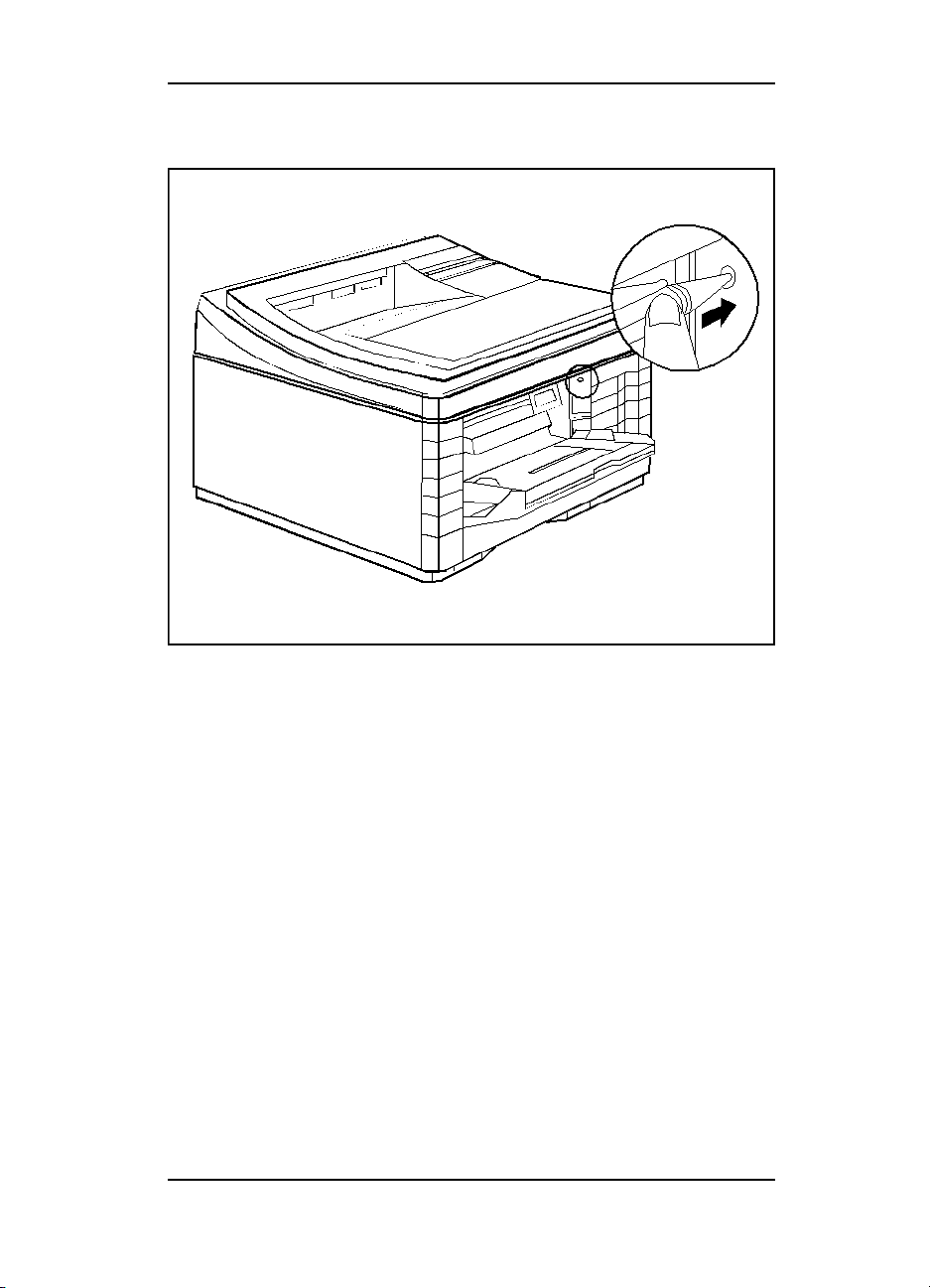
Test Print Button
Figure 3-5 Test Pr int Button Location
The Test Print button access hole is located on the side of the
printer. Press the Test Print button using a tool similar to a
paper clip (see Figure 3-5). The 15 ENGINE TEST only prints from
the PC tray (Tray 2).
Configuration 3-29
Page 66
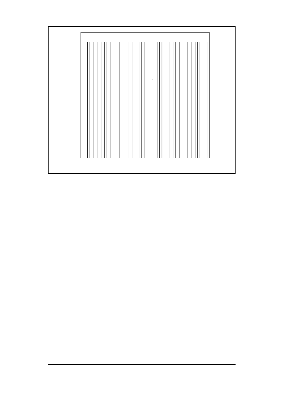
Figure 3-6 Test Print Pattern
Pressing the Test Print button will initiate a 15 ENGINE TEST.
This is an engine test only. The Format PCA is bypassed while
printing this test, although a formatter problem can interfere
with this test. A page of vertical lines is printed if the print
engine is operating correctly (see Figure 3-6).
3-30 Configuration
Page 67

System Configuration
MS-DOS System Configuration
To communicate properly with the printer, the MS-DOS
environment requires the addition or modification of MODE
commands in the AUTOEXEC.BAT file. Add or modify the
MODE command(s), depending on the interface configuration, as
follows:
Parallel DOS Commands
Most IBM PC and AT compatible computers default to a parallel
printer port. To ensure that information is sent to your parallel
printer port, type the following MS-DOS command at your
MS-DOS prompt or include it in your AUTOEXEC.BAT file:
MODE LPT1:,,P
For MS-DOS version 4.0 and above, enter:
MODE LPT1:,,B
Note
Since the MODE command is an external MS-DOS command (a
program named MODE.COM is run when the MODE command is
invoked), the program file must be contained in the root directory,
or in a directory specified in a preceding PATH command in the
AUTOEXEC.BAT file.
Note
This example assumes that you are using parallel
printer port LPT1. If you are using LPT2 or
LPT3, replace LPT1 in the example with the
printer port that you are using.
After changing the AUTOEXEC.BAT file, reboot
the computer to initiate the changes.
Configuration 3-31
Page 68

Serial MS-DOS Commands
Most IBM compatible computers default to a parallel printer port.
To ensure that information is sent to your serial printer port, type
the following MS-DOS commands at your MS-DOS prompt, or
include them in your AUTOEXEC.BAT file.
MODE COM1:9600,N,8,1,P
MODE LPT1:=COM1
For MS-DOS version 4.0 or above, enter:
MODE COM1:9600,N,8,1,B
MODE LPT1:=COM1
Note
Since the MODE command is an external MS-DOS command (a
program named MODE.COM is run when the MODE command is
invoked), the program file must be contained in the root directory,
or in a directory specified in a preceding PATH command in the
AUTOEXEC.BAT file.
Note
These examples assume that you are using serial
printer COM1. If you are using COM2 or COM3,
replace COM1 with the the printer port that you
are using.
After changing the AUTOEXEC.BAT file, reboot
the computer to initiate the changes.
3-32 Configuration
Page 69

Printer I/O Configuration
Parallel Menu
The default setting for the High Speed Parallel I/O is YES. If it is
set to NO, the interface runs at a slower speed that is compatible
with older computers. When the default is set to YES, the parallel
interface runs at a higher rate supported by newer computers.
Advanced Functions
The Advanced Functions feature of the printer enables
bi-directional communications between the printer and the host.
The default setting is ON. This default setting (ON) must be
active in order to use LaserJet Explorer, the Windows Printing
System, and other software applications and drivers.
Serial Configuration
Use RS-232C serial configuration when the printer is located 11
to 50 feet from the computer. If you need to locate the printer
between 51 and 2000 feet from the computer, use an RS-422A
serial configuration (not available on the LaserJet 4 Plus or 5).
Since the default-printer I/O setting on the printer is parallel,
remember to change the settings on the printer control panel for
serial printing.
Serial Protocol
When printing with a serial configuration, the same protocol
must be set on both the printer and the computer. Protocol on
the printer is set by changing the control panel. Protocol on the
computer is set by using DOS commands. The default protocol
settings are described below.
BAUD Rate
The BAUD-rate setting tells the printer how fast information is
transferred to and from the computer. The default BAUD rate
setting is:
BAUD RATE=9600*.
Configuration 3-33
Page 70

Pacing (Handshaking)
Pacing (or “handshaking”) is a type of communication between
the printer and the computer. This is an important item in the
printer because it allows the printer to tell the computer when to
send information. If the printer is unable to receive information,
for example, when the print buffer is full or when the printer is
out of paper, a signal is sent to the computer to stop sending
information. When the printer is able to resume receiving
information, it sends another signal to the computer to send more
data.
Pacing is set through the control panel’s Serial Menu. Two types
of handshaking are supported by your printer:
• Select DTR/DSR through the Serial Menu’s PACING item if the
computer requires hardware flow control (most personal
computers do). Through the Serial Menu’s DTR POLARITY item,
the DTR polarity can be set to High or Low. The default is DTR
POLARITY=HI
• Select XON/XOFF through the Serial Menu’s PACING item if the
computer requires software flow control (for example, if you
are using a UNIX workstation). Note that status readback
messages are not paced when XON/XOFF is selected. Through
the Serial Menu’s ROBUST XON item, Robust Xon can be set to
ON (the default) or OFF. Note that the ROBUST XON item only
appears under the Serial Menu if XON/XOFF was selected.
3-34 Configuration
Page 71

Serial Cable Pin-outs
The following cable diagrams show the cable pinouts for the most
common serial configurations.
DB-9 RS-232 Serial Connection — HP LaserJet 4
If the computer has a serial port with 9 pins, use the cable or
equivalent for the HP LaserJet 4.
Figure 3-7 24542G Cable Pinout for 25 to 9 Pin Connector
Configuration 3-35
Page 72

DB-25 RS-232 Serial Connection — HP LaserJet 4 Plus/5
If the computer has a serial port with 9 pins, use the C2932A or
equivalent cable for the HP LaserJet 4 Plus.
Figure 3-8 C2932A Cable Pinout for 9 to 9 Pin Connector
3-36 Configuration
Page 73

DB-25 Serial Connection — HP LaserJet 4
If the computer has a serial port with 25 pins, use the 17255D
cable or equivalent for the HP LaserJet 4.
Figure 3-9 17255D Cable Pinout for 25 to 25 Pin Connector
Configuration 3-37
Page 74

DB-25 RS-232 Serial Connection — HP LaserJet 4 Plus/5
If the computer has a serial port with 25 pins, use the C2933A or
equivalent cable for the HP LaserJet 4 Plus.
Figure 3-10 C2933A Cable Pinout for 9 to 25 Pin Connector
3-38 Configuration
Page 75

RS-422A Serial Connection (Not available on the HP
LaserJet 4 Plus or 5 printers)
If you are configuring the computer to use an RS-422A serial port,
you need a special cable. Contact the computer or printer network
manufacturer to see if an RS-422A cable is available. If no cable
is available, contact your computer manufacturer for your
computer pin assignments and have a cable constructed.
Figure 3-11 RS-422A Cable Pinout
RS-422A Serial Configuration (LaserJet 4 only)
The default configuration for the serial port on the printer is for
RS-232C serial communication. To set the printer to use RS-422A
serial communication, change the control panel Serial Menu’s
SERIAL setting to SERIAL=RS-422.
Note
Hardware pacing for RS-422 serial
communication is not available on the printer.
Configuration 3-39
Page 76

Modular I/O Configuration
The printers are equipped with a modular I/O slot. A modular I/O
interface card can be plugged into that slot to increase the
number of interfaces available.
A modular I/O card can provide increased printer performance
when printing from a network. In addition, a modular I/O card
provides the ability to place the printer anywhere on the network.
This eliminates the need to attach the printer directly to a server
or a workstation, and enables you to place your HP LaserJet
printer closer to your network users.
Note
The HP JetDirect Card allows these printers to operate in
multiple operating system networks.
To determine the appropriate MIO solution for a specific host
system/application environment, refer to the latest edition of the
“HP Peripherals Connectivity Solutions Guide.”
When you install a MIO card, you may need to
perform a Cold Reset to reinitialize the printer’s
control panel.
3-40 Configuration
Page 77

Printer Drivers
Install Printer Drivers and Utilities
Printer drivers are specialized programs designed to allow
specific software applications to function with the HP LaserJet
printers. Printer utilities include such things as the HP Explorer
program modules, which enhance the usability of the printer and
provide convenient access to printer features outside of specific
software applications.
How to Obtain Printer Drivers
First, check the software’s printer selection feature to see if the
printer is listed among the available printers. If it is not, run the
software’s SETUP or INSTALL program to install a “printer
driver” or “printer file” for the printer.
Here are some ways to obtain printer drivers and Software
Application Notes for HP LaserJet printers:
• Check the Printing Software package to see if it includes a
driver for your software.
• Order an updated driver from the software vendor.
• Call Hewlett-Packard at 970-339-7009.
• Obtain a driver request form by fax through HP FIRST
(call 1-800-333-1917) U.S. only.
• Download a driver through CompuServe’s HP Forum. To sign
up for CompuServe, call 1-800-524-3388.
Note
While waiting for a specific HP LaserJet printer
driver, you can substitute a similar printer driver
(such as a driver for the HP LaserJet III, IIIP, or
4 printer). These substitute drivers will allow you
to use the printer, but they do not support all of
the printer’s features.
Configuration 3-41
Page 78

DOS Utilities
Use the DOS Utilities to install printer drivers for MS-DOS
applications. Printer driver software for some common software
applications are included the DOS Utilities. See the Doing
Business With HP section of Chapter 1 for information on
software drivers not included with the LaserJet DOS Utilities.
A DOS Utilities disk is shipped with every printer. If the DOS
Utilities is not installed on the host computer, look for the DOS
Utilities software disks in the documentation package that came
with the printer and install the software.
3-42 Configuration
Page 79

Packing the Printer
Repackaging Instructions
The printer warranty is for one-year and must be returned to an
Authorized HP service center for service. If the original packaging
material is no longer available, replacement packing and
shipping material is available from HP’s Support Material
Organization (SMO) for a charge. To order replacement packing
and shipping material, call:
1-800-227-8164 (U.S.)
416-678-9430 (Canada)
To order the shipping box and packing inserts for the printers,
ask for part number C2001-00906.
In other countries, return the printer to the selling dealer or the
HP-authorized service center for your service area.
Packing Checklist
Remove and retain any accessories that were installed in the
•
printer. This includes:
• Toner Cartridge
• Optional Lower Cassette
• Envelope Feeder
Accessory Cartridge
•
•
Duplex Assembly (LaserJet 4 Plus/5)
• Optional Memory, Personality SIMMs, or Flash
• Include print samples that indicate the problem.
• If the problem is associated with media, include 50-100 sheets
of the media causing the problem.
Configuration 3-43
Page 80

Installing The Optional Lower
Cassette
Note
These printers have an optional 500-sheet Lower Cassette which
is installed in the field. Follow these instructions to install the
Lower Cassette.
1 Disconnect the cables from the printer.
2 Unpack the 500-sheet Lower Cassette Assembly.
3 Place the Lower Cassette base (without its paper tray) in the
selected location.
4 Place the printer on top of the Lower Cassette Assembly, as
shown in Figure 3-12.
Note
Please see also the Service Notes section for
proper use and adjustment of the lower cassette.
Install the printer onto the Lower Cassette Base
so that the alignment pins on the cassette base
mate with the holes in the bottom of the printer.
Figure 3-12 Installing the Printer on the Lower Cassette
5 Reconnect the printer cables and run a self test to ensure the
lower cassette is recognized by the printer.
3-44 Configuration
Page 81
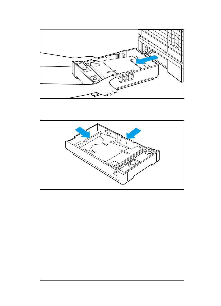
Loading Paper into the Optional Lower Cassette
Figure 3-13 Pull the cassette tray straight out of the printer.
Figure 3-14 Adjust the cassette for the paper size you want
to load.
Configuration 3-45
Page 82

Figure 3-15 Slide about 450 sheets of paper into the tray, up
against the adjustable bracket that sets the
paper length.
Figure 3-16 Press down on the stack of paper until the top of
3-46 Configuration
the stack fits under the top edge of the back
green bracket.
Page 83

Figure 3-17 Push down the left corner of the stack until the
paper is secured undered the metal clip.
EXEC
A4
LEGAL
LETTER
Figure 3-18 Set the knob on the top right of the cassette to
the paper size you have loaded.
Configuration 3-47
Page 84

Figure 3-19 Note: cassette MUST be full before adj usting the
tension.
To adjust the tension, tap the stack of paper
several times and turn the leftmost knob on the
cassette until the arrows on the indicator align.
Tap the stack again and verify the arrows are
still aligned.
Figure 3-20 Slide the cassette back into the Lower Cassette
assembly.
3-48 Configuration
Page 85

Envelope Feeder Installation
For complete information about installing the Envelope Feeder,
see Envelope Feeder User’s Guide. This guide is provided with the
envelope feeder. The instructions below are not intended to
replace the information of the Envelope Feeder User’s Guide.
Note
To install the Envelope Feeder:
1
Turn OFF the printer.
2
Open the MP tray.
3 Remove the black plastic cover from inside the printer (see
Figure 3-21).
The LaserJet 4, 4 Plus, and 5 printers all use
different envelope feeder products.
Figure 3-21 Remove the Black Plastic C over
Configuration 3-49
Page 86

Figure 3-22 Install the Envelope Feeder
4 Insert the Envelope Feeder firmly into the printer (see Figure
3-22).
5 Turn ON the printer.
LaserJet 4 and 4 Plus
The envelope size (EE TRAY=) appears on the display when the
envelope feeder is installed and loaded with envelopes. The
envelope size can be selected through the Control Panel. Paper
jams can result if the envelope size selected does not match the
envelopes loaded into the envelope feeder.
LaserJet 5
The envelope size (ENV FEED=) appears in the CONFIG MENU when
the envelope feeder is installed. The envelope size can be selected
in the CONFIG MENU. Paper jams can result if the envelope size
selected does not match the envelopes loaded into the envelope
feeder.
Note
3-50 Configuration
It is not necessary to configure the Envelope
Feeder to the printer through the printer’s
Control Panel. The printer automatically
recognizes the presence of the Envelope Feeder
and prints from the feeder as the software
requires.
Page 87

SIMM Installation
SIMM installation is covered in detail in the the printer’s User’s
Manual and in the kit that accompanies the SIMM. The
instructions shown here are not intended to replace these sources.
Follow these instructions to install memory, language, and flash
SIMM boards. Install all types of SIMM boards in the same
manner.
Protecting the SIMM Board
SIMM boards can be damaged easily by small amounts of static
electricity. To prevent damage from static electricity:
• Touch the surface of the antistatic package before removing
the board from its package. When handling the board,
frequently touch bare metal on the printer or the antistatic
bag, or wear an antistatic wrist strap.
• Avoid moving about the work area to prevent generating static
electricity.
• Handle the board carefully at all times. Avoid flexing it or
touching its components.
Configuration 3-51
Page 88

Any SIMM board can be installed in any of the four SIMM slots.
Because the slots are close together, we recommend installing
them from right to left, starting with slot 1 and ending with slot 4.
Figure 3-23 Identifying the Four SIMM Slots
3-52 Configuration
Page 89

Memory Requirements
A page’s complexity (rules, graphics, or dense text) may exceed
the printer’s ability to create the image rapidly enough to keep
pace with the printing process. If a page is too complex, only part
of the page prints, and some print data loss is likely. In such
cases, a 21 PRINT OVERRUN message (signifying possible loss of
print data) or a Clearable Warning message appears in the
display.
Table 3-12 Minimum Memory Recommendations
LaserJet 4 Only
PCL Only PostScript Only
Resolution 300 dpi 600 dpi 300 dpi 600 dpi
Letter/A4 Pages
1
Page Protect OFF
Legal Pages
1
Page Protect OFF
Letter/A4 Pages
1
Page Protect ON
Legal Pages
1
Page Protect ON
2
2 (1.6)
2 (1.4) 2 (1) 6 (2.3)
2 (1.6) 2 (1.4) 3 (1.7) 6 (1.3)
2 (0.8) 6 (1.9) 2 (1) 6 (2.3)
3 (1.6) 6 (1) 3 (1.7) 6 (1.3)
3
1 More memory may be required if using downloaded soft fonts, forms, or complex
text with a large num ber of downloaded typefaces.
2 Numbers in parentheses indicate the approximate amount of memory available to
the user for data files, downloaded typefaces, and other non-system uses.
3 For P ostScript language applications only, a “mini-legal” page will print with this
amount of memory.
Configuration 3-53
Page 90

Caution
When removing a board from the antistatic
package, avoid touching the metal traces on the
SIMM board.
For memory boards, compare the part number on the outside of
the package to the part number in the table below. If you have
not received the correct board, notify your authorized
Hewlett-Packard dealer immediately.
Table 3-13
SIMM boards
Part Number
Size
HP LaserJet 4/4M
C2063A One MB
C2064A Two MB
C2065A Four MB
C2066A Eight MB
HP LaserJet 4+/4M+/5/5M/5N Size
C 3130A One MB
C3131A Two MB
C 3132A Four MB
C 3133A Eight MB
C 3146A Sixteen MB
The LaserJet 4 Plus Optional Memory (C3130A, C3131A,
C3132A, C3133A, or C3146A) is not compatible with the HP
LaserJet 4. If the LaserJet 4 Plus Optional Memory is installed
in the LaserJet 4, the printer will display a “53.1X.08 ERROR” (X
indicates the position of the SIMMs slot).
3-54 Configuration
Page 91

Accessing the SIMM Slots
Please refer to Chapter 6, Removal and Replacement, for
instructions on removing the SIMMS door to access the slots.
Note that access to the SIMM slots are slightly different for the
various printer models.
Installing the SIMM Boards
Figure 3-24 Positioning the SIMM board with the notch at the
1
Through the open door, you can see the four SIMM board slots
(see previous Figure 3-23). For easiest installation, fill the
slots from right to left, starting with slot 1 (see the diagram on
the SIMM slots door).
2
Remove the SIMM board from the antistatic package. Hold
the board with your forefingers on the side edges and your
thumbs against the back edge. Turn the board so the notch on
one end is on the bottom and the metal teeth face the slot (see
Figure 3-24.
bottom.
Configuration 3-55
Page 92
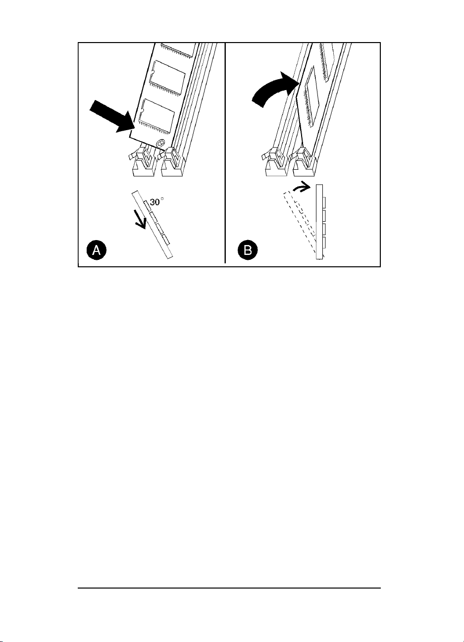
Figure 3-25 Installing the SIMM Board
3 Hold the SIMM board at a 30-degree angle to the slot and
push the edge of the board evenly and firmly into the slot (see
Figure 3-25 callout (A) ).
4 Rotate the SIMM board to the right until the board “clicks”
into the metal locking tabs, securing the board into place (see
Figure 3-25 callout (B)).
5 Gently rock the SIMM board back and forth. If it is seated
correctly, it will not lift away from the slot. If it lifts up, you
have not pushed it firmly enough into the slot. Try again.
6
Replace the SIMM door and screws.
7 Replace the right side cover.
8 Close the top front cover and gently press down on each end
until the cover is completely seated.
3-56 Configuration
Page 93

Testing a SIMM Board
Use the procedures below to print a self-test page to verify SIMM
board installation. Procedures are given for both memory and
PostScript SIMMs.
Memory SIMM
Note
Running a Self Test Printout
Plug in the power cord and turn ON the printer.
1
After a few seconds, 00 READY should appear in the control
2
panel display. If an error message appears, refer to
“Troubleshooting a SIMM Board” later in this chapter.
3 Press [On Line] to take the printer off line.
4 Press [Menu] until TEST MENU appears in the control panel
display.
5 Press [Item] until SELF TEST appears in the control panel
display.
6 Press [Enter] to print a self test.
7 Press [On Line] after the self test printed.
Locate “RAM SIZE” on the self-test printout. This is the amount
of printer memory now installed in the printer.
For the LaserJet 5/5M/5N, the On Line key has
been replaced by the Go key. The Enter key has
been replaced by the Select key.
Configuration 3-57
Page 94

Personality SIMM
(PostScript)
A personality (printer language) SIMM installation can be
verified as outlined below (a PostScript SIMM is used in this
example).
Note
For the LaserJet 5/5M/5N, the On Line key has
been replaced by the Go key. The Enter key has
been replaced by the Select key.
1 Plug in the power cord and turn ON the printer.
2 After a few seconds, the on line indicator should light and 00
READY should appear in the control panel display. If an error
message appears, refer to “Troubleshooting a SIMM Board”
following.
3 Press [On Line to take the printer off line.
4 Press [Menu] until JOB MENU appears in the control panel
display.
5 Press [Item] until PERSONALITY=AUTO*, the default, appears in
the control panel display.
6 Press [+] until PERSONALITY=PS appears in the display. This
indicates that your printer recognizes that PostScript is
installed. If PERSONALITY=PS does not appear, check the
SIMM installation.
7 Press [On Line] to return the printer on line.
3-58 Configuration
Page 95

Troubleshooting a SIMM Board
For more information about the service/error messages below, see
Chapter 7, Troubleshooting.
Service / Error Messages
One of two messages can be generated when your printer is
checking its SIMM internal memory.
61.X SERVICE
where X = 1, 2, 3, or 4
This error indicates a SIMM parity error. The x indicates which
SIMM slot generated the error. If these messages appear first,
check the HP part number to make sure you have the right SIMM
board.
62.X ERROR
where X = 0, 1, 2, 3, 4, or 5
This error indicates your printer identified a problem while
checking memory.
If x=0, the problem is in internal Read Only Memory (ROM) on
the Formatter.
If x = 1, 2, 3, or 4, the problem is in SIMM slot 1, 2, 3, or 4.
If x = 5, the problem is in an external cartridge installed in the
printer.
Refer to chapter 7 for more information.
Configuration 3-59
Page 96

3-60 Configuration
Page 97

Preventive Maintenance
Introduction
The printer requires minimum routine maintenance. Use this
chapter for information on:
• Service Checkpoints. These are the items that must be
cleaned and checked when the Toner Cartridge is replaced, or
before performing periodic maintenance.
• Toner Cartridge information, such as:
• Storing and installing the Toner Cartridge
• Refilled Toner Cartridges
• 16 TONER LOW message
•
Required periodic maintenance on:
• Transfer roller
• Separation pads
• Paper pickup rollers
4
Preventive Maintenance 4-1
Page 98

Life Expectancy of Consumables
Always inspect the components listed in Table 4-1 for wear when
servicing the printer. Replace these components as needed, based
on printer failures or wear, not strictly on usage.
Table 4-1 Selected Service Consumables
DESCRIPTION QTY EST. LIFE
1. Toner Cartridge 1 6800
2. MP (Tray 1) Pickup Roller
Assembly
3. PC (Tray 2) Pickup Roller 1 200,000
4. Separation Pad 1 200,000
5. Transfer Charging Roller 1 200,000
6. Fuser Assembly
(115 V, 50/60 Hz)
Fuser Assembly
(220 V, 50 Hz)
7. LC (Tray 3) Pickup Roller 1 200,000
8. Exhaust Fan 1 25,000 hrs.
Notes:
The
estimated Toner Cartridge life is based on A4 or letter size prints with an average
of 5% toner coverage, and with the density setting at 3.
(pages)
1 200,000
1
200,000
1
200,000
1
When print becomes faint, shake
cartridge to distribute remaining
toner.
Replace roller and separation pad
together.
Look for glazing and cracks.
Look for glazing and grooves.
Replace together with Pickup
Rollers.
May affect print quality and/or
paper jams.
May affect print quality and/or
paper jams. L ook for marks on
rollers.
Look for glazing and grooves.
Replace the Separation Pad.
REMARKS
Note
For part numbers of the components listed in
Table 4-1, see Chapter 8.
4-2 Preventive Maintenance
Page 99

Service Checkpoints
This is a fold-out page 3 panels wide.
Figure 4-1 Maintenance Checkpoints
Preventive Maintenance 4-3
Page 100

Cleaning Your Printer
When it is time to replace the toner cartridge, perform the
cleaning procedures outlined in Figure 4-1.
4-4 Preventive Maintenance
 Loading...