

Page 1

Capacity Upgrade
For C1104/05 Series Jukeboxes
Important! Read This First
This upgrade requires code to be downloaded to the controller PCA and the drives.
BEFORE starting this upgrade, obtain the following:
* The downloadable code required for this upgrade. FTP this code
from hpgrsg.gr.hp.com (15.38.89.10
Further download instructions are available at that address.
* A PC with a SCSI interface and appropriate cables.
* A utility to download the code - DOWNLD2 or HP TOOLSET (Version 1.95ce
or later) from CoComp
) using an "anonymous" login.
HP Part No. C1159-90001
Printed in USA June, 1996
Edition 1 0596
Page 2

Hewlett-Packard Company, 1996
Page 3

Capacity Upgrade For C1104/05 Jukeboxes
Before upgrade:
(# of drives and slots)
C1104F/G/H
(4 drives, 128 slots)
C1105F/G/H
(6 drives, 128 slots)
Table 1: C1104/05 Series Capacity Upgrade Options
a. After you install this capacity upgrade (C1159F/G/H), you are able to install 1
or more 2-drive upgrades ( C1158F/G/H).
Upgraded to the equivalent of a:
C1107F/G/H (238 slots)
a
ESD Precautions
The optical disk jukebox contains very sensitive electrical components. It is EXTREMELY IMPORTANT that you follow the proper procedures for preventing ESD (Electrostatic Discharge). Use wristgrounding straps, anti-static mats, and anti-static work stations when removing and replacing the
major assemblies.
Caution
Failure to follow proper procedures could lead to intermittent
failures and/or premature hard failures in the disk controller
and mechanism.
Tools Required
The following tools are needed for assembly/disassembly of the autochanger:
• Torx driver with the following bits: T-10, T-15, T-20
• 1/4-inch hex nut driver
3
Page 4

Kit Contents
• 24 - magazine guides, 8 slot (makes 12 sets) — # C1100-44x00
• 6 - magazine guides, 6 slot (makes 3 sets) — # C1160-41x15
• 1 - interposer PCA — # C1107-60x05
• 1 - controller PCA — # C1107-60x01
• 1 - power Supply (200W)— # C1107-60x32
• 1 - short AC power cable (to 12V) — # C1107-60x50
• 1 - SCSI cable (lower) — # C1107-60x60
• 1 - interposer (lower) power cable —- # C1107-60x68
• 1 - enclosure for SCSI repeater/converter PCA — # C1107-60x81
• 1 - SCSI repeater/converter/LUN PCA — # C1107-60x08
• 1 - SCSI terminator, single-ended — # 1250-2548
• 1 - SCSI terminator, wide differential — # A1658-62024
• 3 - drive brackets — # C1107-60x47
• 12 - screws (RLG) — # 0515-2282
• 6 - hex standoff screws — # 0380-4416
• 1 - ferrite cable clip — # 9170-1648
• 2 - product upgrade label sheets (Upgrade to: ) — # 5181-9902
• 1 - 600FX name plate — # C1107-84x09 (C1159F and C1159G kits only)
• 1 - these instructions
Note
The “x” in the part numbers listed in the following parts tables
represents a number from “0” to “9” depending on the
revision of the part. For example, if the part is newly
released, the number will be “0”. The first time the part is
revised, the number increments to “1”; the second time the
part is revised, the number increments to“2”, and so on.
If you are unsure of the current part number, enter a “0” or a
“1” in place of the “x” when checking your parts database and
the current part number will be displayed.
4
Page 5

Before You Begin
Caution
Do NOT switch off power to the jukebox until you are sure the
SCSI bus is inactive
SCSI bus is active can cause data loss and/or indeterminate
bus states.
When doing this upgrade, be sure that disk cartridges are not
moved from their original slot locations.
the cartridges, record their SLOT LOCATIONS and
ORIENTATION so they can be replaced to their ORIGINAL
positions. Failure to follow this practice results in a serious
loss of file system integrity.
1. Look in the jukebox front "window" and make sure that there are no disks in any drive.
Use the control panel to eject any disk still in a drive.
. Switching off the jukebox when the
If you need to remove
2. Bring the jukebox “down.”
Procedures for bringing this jukebox offline depend on the specific host system. Coordinate with
the system administrator to prepare this jukebox for the upgrade. This may involve “downing” the
host system also.
3. Remove power from the jukebox.
4. Disconnect the SCSI interface from the host.
5
Page 6
Installing a Capacity Upgrade
Caution
When doing this conversion, be sure that disk cartridges are
not moved from their original slot locations.
remove the cartridges, record their SLOT LOCATIONS and
ORIENTATION so they can be replaced to their ORIGINAL
positions. Failure to follow this practice results in a serious
loss of file system integrity.
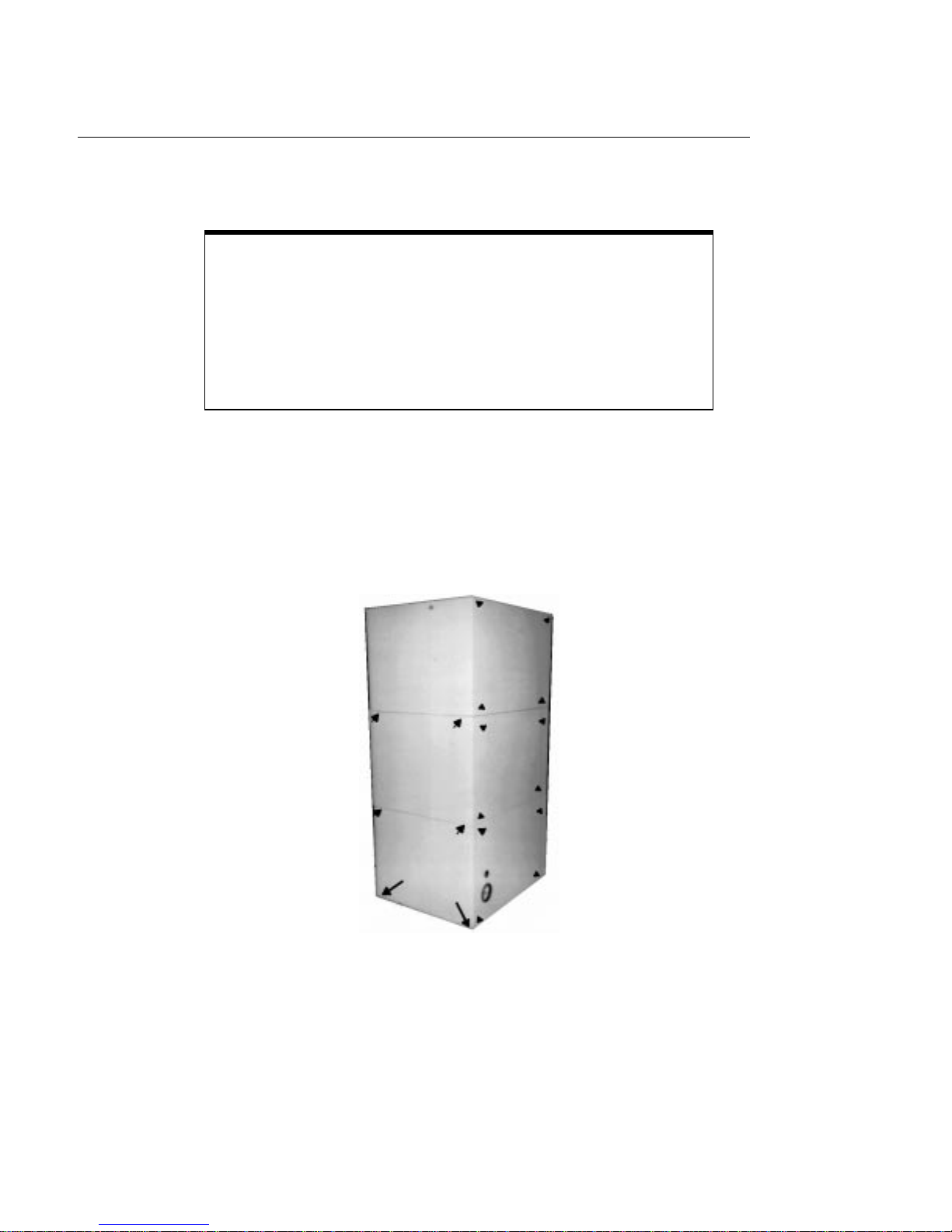
1. Remove the 3 right-side panels and the 3 back panels.
To remove the 3 right-side panels, you must start at the bottom panel. The bottom panel may have
2 slotted/T-15 T orx screws at each corner (long arrows in Figure 1) if the customer has re-installed
them after installation. The 2 screws at the bottom of each of the other side panels are T-20.
The rear panels may be removed in any order. Each panel is held by 4 T-20 screws.
If you need to
Figure 1: Screws on side and rear panels
2. Remove the 2 RFI panels (see Figure 2).
There are 6 T-20 screws around the edge of each panel.
6
Page 7

Figure 2: Screws on the RFI panel
Caution
Put on a grounding strap to work inside the outer shell of this
jukebox.
3. Install the 110 cartridge slots. Refer to Figure 1 for an overview of where these slots will be added
Note
Fot this kit, magazines (sets of cartridge slots) come in 12 sets
of 8-slot and 3 sets of 6-slot. Each magazine (set of cartridge
slots) uses two sides.
Although there are 114 slots added, only 110 of these slots
can be used by the jukebox.
7
Page 8

Figure 3: Location of 8-slot and 6-slot magazine sets after upgrade
Figure 4: Magazine tabs and spring latch (right side)
8
Page 9

The magazine guide above is shown as it is oriented when
placing it into the inside right of each stack (as you face the
stacks).
Place the leading tabs (top right in the picture) into the slots
farthest in, then rotate the magazine guide into the stack,
catching the trailing tabs (lower left arrows in picture). Push
the guide against the stack and forward until you (hear/feel)
the latch click into the wall of the stack (the latch is the
"angle"shown in the lower left of the picture).
If this latch does not catch (click into place), the guide is
not correctly mounted and could come out during use.
When installing the magazines in the left stack (as you face
the interior of the jukebox during this step) you will have to
slip the magazines under a small groove running along the
length of the stack.
4. Install the additional power supply on the right side as seen in Figure 5.
Figure 5: Power supply location
9
Page 10

a. Place the power supply on the power supply bracket. Make sure all cables are out of the
way.
b. Mount the new power supply with 2 T-20 screws through mount tabs on the top of the
power supply.
5. Install the new SCSI interface module.
Note
The new interface module you will assemble has 2 SCSI
interface PCAs to support future upgrades to the number of
drives (upgrading to 8, 10, or 12 drives).
Figure 6: Location of the interface module and mounting screws
a. Remove the current interface module.
1. Disconnect the cables from the module.
2. Remove the 4 T-20 mounting screws and rotate the module down.
3. Remove all cables from the interface PCA.
a. Remove the SCSI interface PCA from the module by removing the 6 T -15 mounting screws.
10
Page 11

((Place the interface module and interface board aside.))
4. Install the new, lower interposer PCA below the one currently in the jukebox.
Figure 6 shows the location of this PCA and Figure 7 shows how cables are routed from the upper
interposer PCA and the new, lower interposer PCA.
Figure 7: Correct placement of the interposer PCA
a. Attach the loose end of the new interposer-to-interface SCSI cable to the interposer PCA by
bringing the cable BEHIND the board up and over the top, connecting it on the top of the
board. Put the PCA in place against its screw mounts on the chassis.
Note
There are NO CABLES connected to the BOTTOM
connection of the new, lower interposer PCA.
b. Mount the PCA by inserting and tightening the 8 T-20 screws.
c. Attach the GPIO cable from the controller PCA to the top left of the lower interposer PCA.
Refer to Figure 8 for the location of this cable.
11
Page 12

.
Figure 8: GPIO cable connection to the lower interposer PCA
d. Place the additional ferrite clip that comes with this kit around the new SCSI cable going to
the upper interposer PCA. Attach this clip on top of the one is currently there. See Figure 9
for placement.
Figure 9: Placement of the ferrite clips on both interposer SCSI cables
12
Page 13

5. Attach the power cables. Refer to Figure 10 for proper power cable connections.
Figure 10: Paths for connection of power cables
a. Connect the interposer PCA power cable.
1. Connect the 2 connectors on the power cable to the lower interposer PCA (at the
upper and middle power connectors on the right side of the interposer PCA).
2. Route this cable to the new power supply along the path indicated in Figure 10.
Use the stake-in clamps along the path.
b. Connect the interposer PCA power cable connectors to the connectors on the top of the new
power supply as shown in the detail of Figure 10.
c. Attach the short AC power cable to the bottom of the new power supply and to the power
distributor PCA as shown in Figure 10.
3. Install the "old" SCSI interface PCA in the new interface module.
a. Mount the SCSI PCA you removed from the previous module into the new enclosure. Use
the 6, 1/4-inch hex standoff screws from the upgrade kit. See Figure 11.
b. Install the new SCSI PCA on top of the first PCA. Mount its screws into the hex standoffs.
Use the T -15 screws that were previously installed.Add a jumper to the left-most position
of the jumper block shown in Figure 12.
13
Page 14

.
Figure 11: Installing the first (lower) PCA with standoff screws
Figure 12: Installing the second (upper) PCA - adding jumper
c. Mount the new interface module on the jukebox.
1. Connect the upper interposer-to-interface SCSI cable to the “bottom” SCSI
interface PCA (“bottom” is closest to the module enclosure). Mount the lower
interposer-to-interface SCSI cable to the “top” PCA. Reconnect the 2 GPIO
cables and the power cables. Refer to Figure 12 for proper cable connections.
14
Page 15

Figure 13: Connecting Cables to the SCSI rpeater/converter PCA
2. Rotate the interface module up against the jukebox chassis, insert and tighten
the 4 T-20 mounting screws.
Caution
Make sure that the cables are not pinched by the side of the
interface module, and can be moved freely.
3. Replace cables and terminators as required by customer needs.
Note
The C1104F/G/H (1/2 capacity) jukebox was shipped with a
single-ended and a differential terminator. This capacity
upgrade includes additional single-ended and differential
terminators for use on the new interface PCA, if necessary.
7. Install the new controller PCA.
Figure 14: Location of the controller PCA
15
Page 16

Note
In the first step, below, leave the top cables attached to the
controller PCA to hold this PCA in place when its mounting
screws are removed.
a. Remove all cables (except the top cables - see Note above) from the controller PCA.
b. Remove the 7 T -20 screws holding the controller PCA in place, remove the final top cables,
and remove the PCA.
c. Place the new controller PCA in position by attaching the top cables to hold it.
d. Insert and tighten the 7 T-20 mounting screws.
e. Reconnect the remaining cables. See Note below.
7. Install the 3 drive enclosures.
Note
IF YOU WILL ALSO BE DOING A DRIVE UPGRADE,
wait until you are ready to install the new drives and install the
drive enclosures as part of that procedure. If doing a drive
upgrade, skip to Step 8.
16
a. Remove the 2 T-20 screws from each of the 3 front plates that cover the lower drive loca-
tions.
b. Insert each drive enclosure and secure it by inserting and tightening 2 T-20 screws.
Note
The RFI strips tend to compress the enclosure sides. Keep the
front of the enclosure spread so that the slots on the bottom of
the enclosure correctly fit into the tabs.
c. Connect the 3 drive fan power cables from the each of the new drive enclosures to the lower
interposer PCA connections (see Figure 15).
Page 17

.
Figure 15: Connecting the drive fan cables to the lower interposer PCA
8. Download the latest code to the controller PCA and drives.
You will use an external SCSI connector on the interface module.
9. Run the Wellness Test to verify installation.
10. Remove power from the jukebox.
11. Label the jukebox (see the following Note for guidance on which label to use).
a. Place the appropriate product upgrade label over the previous lable as shown in Figure 16. Use
a drive-upgrade-based or capacity-upgrade-based label as explained in the following Note. Do
not cover the serial number.
The label is located on the bottom ledge of the jukebox, under the interface module enclosure.
Figure 16: Positioning the upgrade label on the old label
17
Page 18

Note
Choose the correct product label based on the FINAL product
configuration
1/2 capacity (128 slots)
6 drives = C1105 F/G/H
Full capacity (238 slots)
6 drives = (use labels from capacity upgrade kit)
8 drives = C1108F/G/H
10 drives = C1110F/G/H
12 drives = C1112F/G/H
Choose the label that has the same product suffiix (F, G, or H)
that the original product had.
12. Reconnect external SCSI interface cables as previously installed at the site.
13. Replace the 3 right-side and 3 rear panels.
14. Bring the jukebox online according to site requirements.
18
 Loading...