

Page 1
Model C100/110 Owner’s Guide
HEWLETT
PACKARD
HP Part No. A4200-90014
Edition E0995
Printed in U.S.A.
®
Page 2

Hewlett-Packard Co. 1995
Printing History
First Printing: September 1995
UNIX is a registered trademark in the United States and other countries,
licensed exclusively through X/Open Company Limited.
NOTICE
The information contained in this document is subject to change without
notice.
HEWLETT -PACKARD MAKES NO WARRANTY OF ANY KIND WITH
REGARD TO THIS MATERIAL INCLUDING BUT NOT LIMITED TO
THE IMPLIED WARRANTIES OF MERCHANTABILITY AND FITNESS FOR A PARTICULAR PURPOSE. Hewlett-Packard shall not be liable for errors contained herein or for incidental or consequential damages in
connection with the furnishing, performance or use of this material.
Hewlett-Packard assumes no responsibility for the use or reliability of its
software on equipment that is not furnished by Hewlett-Packard.
This document contains proprietary information that is protected by copyright. All rights reserved. No part of this document may be photocopied,
reproduced or translated to another language without the prior written consent of Hewlett-Packard Company.
RESTRICTED RIGHTS LEGEND. Use, duplication, or disclosure by government is subject to restrictions as set forth in subdivision (c) (1) (ii) of the
Rights in Technical Data and Computer Software Clause at DFARS
252.227.7013. Hewlett-Packard Co., 3000 Hanover St., Palo Alto, CA
94304.
10 9 8 7 6 5 4 3 2 1
Page 3

Contents
Contents
Preface xvii
1 System Overview
Product Description 3
System Unit Front Panel Controls and LEDs5
System Power Switch 6
Power LED 6
System LEDs 6
Audio Controls 7
Removable Storage Devices 7
iii
Page 4

Contents
System Unit Rear Panel Connectors 8
Security Loop 9
Audio Connectors 10
Keyboard Connectors 12
HP Parallel I/O Connector 12
802.3 Network Connectors 12
Serial I/O Connectors 12
SCSI Connectors 13
TOC Button 14
Power Cord Connector 14
Monitors 15
Keyboards 16
Keyboard Differences 16
Pointing Devices 19
Operating System Overview 20
Important Information You Need to Note 21
LANIC ID 21
SCSI ID and Device File Information for HP-UX 9.05 23
SCSI ID and Device File Information for HP-UX 10.0 23
Networking Overview 25
Mail 25
telnet 25
rlogin 26
ftp 26
rcp 26
NFS 26
iv
Page 5

Contents
2 Setting Up Your Printer
Gathering Printer Information 29
Setting Up a Local Printer Using SAM 30
Setting Up Your Printer for Network Printing 35
Printing a File 37
Solving Printer Problems 38
3 Using Your CD-ROM Drive
CD-ROM Drive and CD-ROM Media Descriptions 41
CD-ROM Drive 41
CD-ROM Media 44
Operating the CD-ROM Drive 45
Loading and Unloading a CD-ROM in the Disc Tray 45
Verifying the CD-ROM Drive Operation 51
Using Device Files 53
Mounting and Unmounting a CD-ROM Disc 54
Mounting a CD-ROM Disc Using SAM 54
Unmounting a CD-ROM Disc Using SAM 57
Reading the Busy Light 59
Troubleshooting 61
v
Page 6

Contents
4 Using Your Digital Data Storage (DDS) Tape Drive
DDS Tape Drive and Data Cassette Descriptions 65
DDS Drive 65
Data Cassettes 68
Setting the Write-Protect Tab on a Data Cassette 69
Operating the DDS Tape Drive 71
Loading and Unloading a Data Cassette 71
Verifying the DDS Tape Drive Operation 72
Using Device Files 73
Archiving Data in Compressed and Noncompressed Mode 74
Writing to a Data Cassette 74
Restoring Files from a Data Cassette to Your System 75
Listing the Files on a Data Cassette 75
Further Command Information 76
Media Interchangeability Restrictions 76
Troubleshooting 77
Ordering Information 78
vi
Page 7

Contents
5 Using Your 3.5-Inch Floppy Disk Drive
Using the Floppy Diskette 81
Setting the Write-Protect Tab on a Diskette 81
Inserting and Removing a Diskette 82
Operating the Floppy Drive 83
Verifying the Floppy Drive Configuration 83
Using Device Files 84
Formatting a New Diskette 85
Transferring Data To and From a Floppy Diskette 86
Saving Files to a Floppy Diskette 86
Restoring Files from a Floppy Diskette to Your System 87
Listing the Files on a Floppy Diskette 88
For More Information 89
Configuring the Floppy Driver 90
Troubleshooting 91
Ordering Information 91
vii
Page 8

Contents
6 Solving Problems
Common Problems and Solutions 95
Problems with Powering Up the System 95
Problems Loading and Booting the Operating System 96
Problems with the 802.3 Network 96
Problems Using a Hard Disk Drive 97
Problems Using the CD-ROM Drive 98
Problems Using the DDS Tape Drive 99
Problems Using the Floppy Disk Drive 100
Dealing with a Boot Failure 101
Running System Verification Tests 102
A Safety and Regulatory Statements
Emissions Regulations 107
Federal Communications Commission (FCC) 107
VCCI Class 2 ITE 108
108
Emissions Regulations Compliance 108
Acoustics 108
Regulation On Noise Declaration For Machines -3. GSGV 108
Electrostatic Discharge (ESD) Precautions 109
Safety Statement 110
Laser Safety Statement (U.S.A. Only) 111
Warnings and Cautions 112
viii
Page 9

Contents
B Changing Your Workstation’s Hardware Configuration
Checking the SCSI IDs 115
Preparing Your Workstation 117
Installing Storage Devices 119
Preparing to Install Your Storage Device 120
Installing a CD-ROM or a DDS-Format Tape Drive 125
Installing a Floppy Drive 127
Installing a Hard Disk Drive in Position 1 129
Installing a Hard Disk Drive in Position 3 or Position 4 131
Replacing the Storage Tray 134
Configuring a Hard Disk Drive 136
Removing the Main Tray Assembly 139
Replacing the Main Tray Assembly 141
Installing Additional memory 143
Installing an EISA or GSC Option Board 147
Graphics Paths 148
Installing the Option Board 149
Replacing the Battery 154
Changing Your Monitor Type 155
Setting the Monitor Type from the Boot Console Interface 155
Setting the Monitor Type at Power On 155
ix
Page 10

Contents
C SCSI Connections
SCSI Bus Differences 159
SCSI Restrictions 161
Cables 161
Connectors and Terminators 162
SCSI Configuration Constraints 162
Determining SCSI Bus Length 165
Single-Ended SCSI-2 Bus Length 165
Fast, Wide Differential SCSI Bus Length 167
Assigning SCSI Device IDs 168
Single-Ended Standard System SCSI Device IDs 170
Fast, Wide Differential SCSI IDs 172
Connecting to the SCSI Ports 173
System SCSI Port Connection 173
D The Boot Console Interface
Boot Console Interface Features 177
Accessing the Boot Console Interface 180
Booting Your Workstation 181
Searching for Bootable Media 183
Resetting Your Workstation 184
Displaying and Setting Paths 185
Displaying and Setting the Monitor Type 187
x
Page 11

Contents
The Monitor Command 187
Displaying the Current Monitor Configuration 188
Setting the Monitor Type 189
Setting the Monitor Type at Power On 193
Displaying the Current Memory Configuration 194
Sample Output 1 195
Sample Output 2 196
Displaying the Status of the EISA Slots 197
Setting the Auto Boot and Auto Search Flags 198
Displaying and Setting the Fastboot Mode 200
Displaying the LAN Station Address 201
Displaying System Information 202
Displaying PIM Information 203
xi
Page 12

Figures
Contents
System Unit Front Panel Controls 5
System Unit Rear Panel Connectors 9
Opening the Toolbox Subpanel 30
Opening the General Toolbox 30
Opening the System_Admin Toolbox 31
Executing the SAM Icon 31
CD-ROM Drive Controls and Features 42
CD-ROM Disc Tray 45
Placing a CD-ROM Disc in a Horizontally Mounted Drive 46
Removing a CD-ROM Disc From a Horizontally Mounted Drive 47
Releasing the Disc Holder Retainers 48
Placing a CD-ROM Disc in a Vertically Mounted Drive 49
Removing a CD-ROM Disc From a Vertically Mounted Drive 50
DDS Drive Controls and Indicators 65
DDS Tape Drive LED Display Codes 67
Setting the Write-Protect Tab on a DDS Tape 70
Loading and Unloading a Data Cassette 71
Setting the Write-Protect Tab on a Floppy Diskette 81
xii
Page 13

Figures
Contents
Inserting and Removing a Floppy Diskette 82
Removing the Floor Stand 118
Disk Tray Positions 121
Mounting the Storage Device Slides 122
Mounting the Disk Shield 123
Removing the Storage Tray 124
Removing a Disk Filler Panel 125
Installing a CD-ROM or DDS Tape 126
Removing a Disk Filler Panel 127
Installing a Floppy Drive 128
Removing a Disk Filler Panel 129
Installing a Hard Disk Drive in Position 1 130
Removing the Disk Interconnect Board 131
Installing a Hard Disk Drive 132
Installing the Disk Interconnect Board 133
Installing the Storage Tray Assembly 134
Removing Main Tray Assembly 139
Replacing the Main Tray Assembly 141
xiii
Page 14

Contents
Memory Module Location 145
Installing Memory Cards 146
EISA/GSC Slots from Outside the System Unit 147
Rotating the Fan 149
Removing the EISA Retainer 149
Removing the EISA Slider and Blank Plate 150
Installing an Option Board 151
Installing the EISA Retainer and EISA Slider 152
Securing the Fan 153
Removing the Battery 154
Rear Panel SCSI Connectors without Terminators 173
xiv
Page 15

Tables
Contents
Audio Electrical Specifications 11
Serial I/O Pins 13
PS2 Keyboard and ITF Keyboard Equivalent Keys 17
Sample LANSCAN COMMAND TABLE 22
CD-ROM Drive Operating Controls and Features 43
Power Up Problems 95
Problems Loading and Booting the Operating System 96
Problems with the 802.3 Network 96
Problems Using a Hard Disk Drive 97
Problems Using the CD-ROM Drive 98
Problems Using the DDS Tape Drive 99
Problems Using the Floppy Disk Drive 100
Default SCSI IDs 120
Storage Configurations 121
C100/C110 Memory Configurations 144
SCSI Bus Differences 159
SCSI Bus Addresses, ID Numbers, and Arbitration Priorities 160
Single-Ended SCSI-2 Bus Configuration Constraints 163
xv
Page 16

Tables
Contents
Fast, Wide Differential SCSI Bus Configuration Constraints 164
Bus Length Worksheet for Single-Ended SCSI Bus 166
Fats, Wide SCSI Bus Length Worksheet for Fast, Wide Differential SCSI Bus 167
Single-Ended SCSI Device IDs 171
Fast, Wide Differential SCSI Device Drives and Device ID 172
System Paths 185
Mnemonic Style Notation 185
Graphics Configurations 192
xvi
Page 17

1
System Overview
1
Page 18

System Overview
This chapter introduces the HP 9000 C100/C110 workstation. Its purpose is
to familiarize you with your workstation and its controls and indicators. The
information is presented in the following sections:
• Product Description
• System unit front panel controls and LEDs
• System unit rear panel connectors
• Monitors
• Keyboards
• Pointing devices
• Operating system overview
• Important information you need to note
• Networking overview
NOTICE: The instructions in this chapter assume you are using HP-UX
version 9.05 or greater operating system with HP VUE version 3.0
interface.
2
Page 19

System Overview
Product Description
Product Description
This workstation has the following key features:
• Processor Performance C100, 100 Mhz; C110, 120 Mhz
• Operating System Native HP-UX (version 9.05 or greater)
• User Interface HP VUE version 3.0 graphical user interface
• Compatibility Source and binary code compatible with the Series
700 product family
• Optional Graphics:
Fast 2D color graphics; choice of 2 or 3 head
HCRX-8Z Fast 8-plane or 24-plane graphics
HP VISUALIZE-8\24 Accelerated 8-plane or 24-plane 3D graphics
HP VISUALIZE-48 24/24 image planes, 8 overlay planes, 24-bit Z buffer
3D graphics
• Main Memory 32 MB to 512 MB in pairs of 16 MB or 64 MB modules.
Four pairs maximum
3
Page 20

System Overview
Product Description
• Internal Storage Devices:
Fast, Wide SCSI Hard Disk Drives:
1-inch Low Profile (up to three)
1.6-inch Full Height (one)
Single-Ended SCSI Removable Media:
CD-ROM Drive
or
2.0/4.0 GB, 4-mm DDS-Format Tape Drive
3.5-inch Floppy Disk Drive (not a SCSI Device)
• Standard Network Ethernet IEEE 802.3 AUI
RJ45, UTP Twisted Pair
• Standard I/O One Single-Ended, 8-bit (for removable devices)
5 MB/sec synchronous 1.5 MB/sec asynchronous
50-pin, high density SCSI connector
One Fast, Wide SCSI (for hard disk drives)
20 MB/sec synchronous 68-pin, high-density connector
Two Serial Interfaces RS232C, 9-pin male
One Parallel Interface, Centronics, BUSY handshake
25 pin female
Audio Line-in, Line-out, Mic, and Headphone
One HP-HIL connector
Two PS/2 ports
• EISA/GSC 4 slots total; 3 EISA or GSC and 1 GSC only
• Keyboards PS/2 Keyboard (mouse)
or
ITF Keyboard (also known as HP HIL) (HP HIL mouse)
4
Page 21
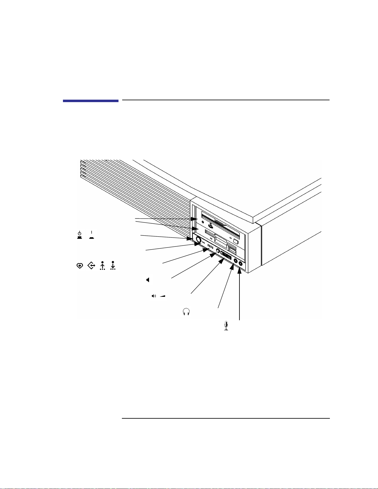
System Unit Front Panel Controls and LEDs
Before powering on your system, you should become familiar with the
system unit controls.
Figure 1 shows the system unit front panel controls.
Removable
Storage Devices
Power Switch
System Overview
System Unit Front Panel Controls and LEDs
Power LED
System LEDs
Mute
Volume
Headset
Figure 1 System Unit Front Panel Controls
Mic
5
Page 22

System Overview
System Unit Front Panel Controls and LEDs
System Power Switch
Use the Power switch to power the system unit on and off.
NOTICE: There is no need to manually shut down the HP-UX operating system on
your workstation before powering it off. When you turn off the power
switch, your workstation automatically shuts down the operating system
before terminating the power.
Power LED
The Power LED lights when the system unit power is on.
System LEDs
The system LEDs indicate the status of your workstation. In the event of a
system problem, the LEDs are lighted in different patterns to indicate error
codes. See Chapter 6 for a complete list of the system LED error codes.
LED 4 - System Heartbeat
LED 3 - SCSI Bus Activity
LED 2 - Network Transmit
LED 1 - Network Receive
6
Page 23

System Overview
System Unit Front Panel Controls and LEDs
Audio Controls
Next to the system LEDs are the following audio controls:
Headset Jack Accommodates mini-headphones with a 3.5-mm diameter
miniature stereo plug.
Volume Control Adjusts the audio output volume to the headset jack or line
out.
Mic Jack Accommodates microphones with a 3.5-mm diameter min-
iature stereo plug.
Mute Button Turns off the audio output to line out and speaker only.
NOTICE: The volume Control, Headphone Jack, and Microphone Jack Features of
the CD-ROM are supported through applications only
For more information on the features and electrical specifications, see
“Audio Connectors” later in this chapter.
Removable Storage Devices
The model C100/110 supports the following removable storage devices:
• CD-ROM Disc Drive or DDS-Format Tape Drive
• Floppy Diskette Drive
NOTICES: Due to space limitations, a DDS-format tape drive and a CD-ROM drive
cannot both be mounted in the system at the same time.
A description of each drive’s controls and indicators is in the chapter
describing that device, later in this book.
7
Page 24

System Overview
System Unit Rear Panel Connectors
System Unit Rear Panel Connectors
This section describes the following connectors on the system unit’s rear
panel:
• Security Loop
• Audio Line IN and Line OUT connectors
• PS/2 keyboard and mouse connectors
• HP parallel Centronics I/O connector
• 802.3 AUI LAN connector
• 802.3 TP (Twisted Pair) LAN connector
• Serial I/O connectors
• HP HIL connectors (keyboard, mouse, optional HIL devices)
• Monitor connector
• SCSI connectors (including fast, wide SCSI and single-ended SCSI)
• TOC button (Transfer of Control)
• Power cord connector
NOTICE: To maintain electro-magnetic and radio frequency emissions compliance,
verify that all cables are fully seated and properly fastened.
Figure 2 shows the locations of the connectors on the system unit’s rear
panel.
8
Page 25

Monitor
System Overview
System Unit Rear Panel Connectors
Power
TOC
LAN-AUI
LAN-TP
Serial 1
Serial 2
PS/2 Mouse
PS/2 Keyboard
HP Parallel
Single-ended SCSI
Fast, Wide SCSI
Audio Line Out
Audio Line In
Security Loop
Figure 2 System Unit Rear Panel Connectors
Security Loop
The security loop provides a means of locking the storage tray, with a padlock or other locking device, to prevent unauthorized removal from the system.
HP HIL
9
Page 26

System Overview
System Unit Rear Panel Connectors
Audio Connectors
Your workstation has audio input and output capability through external
input and output connectors on the rear panel and through an internal
speaker. The rear panel contains the Audio IN (stereo line-in) and Audio
OUT (stereo line-out) connectors.
The audio connectors are standard stereo audio mini-jacks. Hewlett-Packard
recommends using gold-plated plugs available through audio retailers for
best quality recording and playback through the external connectors. The
following is a summary of the workstation audio features:
• Audio Features Programmable sample rates:
8kHz, 16kHz, 32kHz, 48kHz, 11.025kHz,
22.05kHz, and 44.1kHz.
Programmable output attenuation:
0 to -96dB in -1.5dB steps
Programmable input gain:
0 to 22.5dB in 1.5dB steps
Input monitoring:
16-bit linear, 8-bit u-law, or A-law coding
• Audio Inputs Line-in
Mono microphone (on the front panel) compatible with 1.5V
phantom supply (bias voltage supplied by the system).
CD-ROM audio (if internal CD-ROM is installed.
• Audio Outputs Line-out
Headphone (on the front panel)
Built-in mono speaker
• Audio CODEC Crystal CS4215
10
Page 27

The audio electrical specification for this workstation are summarized in
Table 1.
Table 1 Audio Electrical Specifications
System Overview
System Unit Rear Panel Connectors
Frequency Response
Input Sensitivity/Impedance
Line In 2.0Vpk/47k ohm
Microphone 22mVpk/1k ohm
Max Output Level/Impedance
Line Out 2.8Vpp/47k ohm
Headphone 2.75Vpp/50 ohm
Speaker (internal) 5.88Vpp/48 ohm
Output Impedance
Line Out 619 ohm
Headphone 118 ohm
Signal to Noise*
Line Out 65 dB
Headphone 61 dB
Speaker 63 dB
Line In 61 dB
Microphone 57 dB
THD (w nominal load)
Line Out -73 dB
Headphone -70 dB
Speaker -68 dB
Line In -75 dB
Microphone -73 dB
25-20,000 Hz
*To convert from dB to number of significant bits, use the formula:
dB
---------------------------
=
'n
20 10log[]
For example, for 61dB S/N then n=61/6 or approx. 10 significant bits, or in other
words, about 6 bits of noise.
dB
------ -
≈
6
11
Page 28

System Overview
System Unit Rear Panel Connectors
Keyboard Connectors
PS/2 Keyboard and Mouse Connectors
The PS/2 connectors provide an interface for a keyboard and a mouse to the
system. Consult the documentation that accompanies each input device for
specific information concerning its use.
HP-HIL Keyboard Connector
The HP HIL connector provides an interface for the ITF Keyboard and its
mouse to the system. Consult the documentation that accompanies each
input device for specific information concerning its use.
HP Parallel I/O Connector
The 25-pin HP Parallel I/O interface uses Centronics interface protocols to
support peripheral devices such as printers and plotters. Consult the documentation that accompanies each peripheral device for specific information
concerning its use.
802.3 Network Connectors
Your workstation has built-in ThickNet LAN-AUI and LAN-TP (Twisted
Pair) connectors for the 802.3 (ETHERNET) network. Connections to ThinLAN networks require an external transceiver. Your workstation will autoselect the correct network setting.
Serial I/O Connectors
You can attach a variety of pointing devices (such as a mouse or trackball),
or peripheral devices to the Serial Input/Output (SIO) ports on the C100/
C110 workstation. Peripheral devices include printers, plotters, modems,
and scanners. Consult the documentation that accompanies each pointing or
peripheral device for specific information concerning its use.
The SIO ports are programmable. You can set functions such as bit rate,
character length, parity , and stop bits. The SIO Ports are used as an interface
for serial asynchronous devices to the CPU. The ports operate at up to a
460.8K baud rate.
12
Page 29

T able 2 shows the SIO connector pin listings. The serial connectors are 9-pin
D-sub connectors. Signal names are those specified in the EIA RS-232 standard.
Table 2 Serial I/O Pins
Pin No. Signal Description
1 DCD Data Carrier Detect
2 RXD Receive Data
3 TXD Transmit Data
4 DTR Data Terminal Ready
5 GND Ground
6 DSR Data Set Ready
7 RTS Request To Send
8 CTS Clear To Send
System Overview
System Unit Rear Panel Connectors
9 RI Ring Indicator
SCSI Connectors
Use the single-ended and fast, wide connectors to connect external SCSI
devices such as DDS-format tape drives and CD-ROM drives. Consult the
documentation that accompanies each SCSI device for specific information
concerning its use. Refer to Appendix C for information about connecting
SCSI devices to your workstation.
NOTICE: When attaching external SCSI devices, be sure to terminate the last device
on the external SCSI bus.
13
Page 30

System Overview
System Unit Rear Panel Connectors
TOC Button
The TOC button resets the system and transfers control from the default
device to an auxiliary device.
Power Cord Connector
Plug the workstation’s power cord into the power cord connector to provide
ac power to the system.
14
Page 31

System Overview
Monitors
Monitors
You can use one of two HP monitors with your workstation:
• 17-inch, 1280x1024 color monitor (A4032A)
• 20-inch, 1280x1024 color monitor (A4033A)
Before using your monitor you should become familiar with its controls,
connectors, and indicators. For this information, consult the documentation
that was packaged with your monitor, or see the HP A4032/A4033 Color
Monitor CE Handbook (A4033-90099).
15
Page 32

System Overview
Keyboards
Keyboards
There are two types of Hewlett-Packard keyboards available for use with
your workstation.
• PS/2 Keyboard (P/S2 interface)
• ITF Keyboard (HP-HIL interface)
CAUTION: Only connect devices that conform to the HP-HIL specification with
Hewlett-Packard HIL ports. Devices that are not HP-HIL compatible but
have similar connectors may appear to be compatible, but will damage
your system.
Keyboard Differences
Aside from the obvious difference in the appearance of the PS/2 and ITF
keyboards due to the arrangement of the keys, there is also a difference in
the keys and their output codes. For example, some keys on one keyboard
may not exist on the other keyboard. These keys generate codes that may not
exist as output from the other keyboard (or may be generated by a different
key). Codes that are generated when a key is pressed are called keycodes.
Some applications expect to use keycodes generated by keys existing on one
of the keyboards (the ITF keyboard for example). Since the keys do not exist
on the other keyboard (the PS/2 keyboard for example), an accommodation
must be made if the PS/2 keyboard is to be used. In most cases, it is still possible to use some other key that is equivalent (generates the same keycode
from a different keycap). To do this, it is necessary to know which keys are
equivalent on the two keyboards. Table 3 compares the equivalent keys of
the ITF and PS/2 keyboards.
NOTICE: Keyboard keys not mentioned inTable 3 are the same on both keyboards.
16
Page 33

Table 3 PS2 Keyboard and ITF Keyboard Equivalent Keys
PS/2 Keycap Symbol ITF Keycap Symbol
F9 blank1 (left)
F10 blank2
F11 blank3
F12 blank4 (right)
PrintScreen / SysReq Menu
Scroll Lock Stop
Pause / Break Break / Reset
Page Up Prev
Num Lock System / User
End Select
System Overview
Keyboards
Page Down Next
Enter Return
Alt (left) Extend Char (left)
Alt (right) Extend Char (right)
No Equivalent Clear Line
No Equivalent Clear Display
No Equivalent Insert Line
No Equivalent Delete Line
No Equivalent Print / Enter
No Equivalent , (number pad)
No Equivalent Tab (number pad)
Esc Esc / Del
Insert Insert Char
17
Page 34

System Overview
Keyboards
Table 3 PS2 Keyboard and ITF Keyboard Equivalent Keys
PS/2 Keycap Symbol ITF Keycap Symbol
Home
Delete Delete Char
Caps Lock Caps
Esc Shifted Esc / Del Shifted
Pause / Break Shifted Break / Reset Shifted
Num Lock Shifted System / User Shifted
0 / Ins (number pad) 0 (number pad)
1 / End (number pad) 1 (number pad)
2 / (number pad)
3 / Pg Dn
(number pad)
4 / (number pad)
6 / (number pad)
7 / Home
(number pad)
8 / (number pad) 8 (number pad)
9 / Pg Up
(number pad)
. / Del (number pad) . (number pad)
Ctrl (left) Ctrl
Ctrl (right) No Equivalent
2 (number pad)
3 (number pad)
4 (number pad)
6 (number pad)
7 (number pad)
9 (number pad)
18
Page 35

System Overview
Pointing Devices
Pointing Devices
You can use an HP three-button mouse, a trackball, or other options as pointing devices using the PS/2 connector, the HIL port, or the Serial ports. For
instructions on using your particular pointing device, see the manual that
came with it.
For general information on using three-button mice and on the various cursor shapes associated with different areas of HP VUE while using a mouse,
see Using Your HP Workstation.
19
Page 36

System Overview
Operating System Overview
Operating System Overview
Your workstation uses the HP-UX operating system, version 9.05 or greater .
Instant Ignition systems, (systems with preloaded software), have X-windows and Hewlett-Packard’s graphical user interface, HP VUE version 3.0,
installed and configured.
Please refer to the “Instant Ignition System Configuration Information”
sheet that shipped with your system for details on configuration.
If you have any questions about Instant Ignition, refer to Using Your HP
Workstation for more information.
NOTICE: When you power on your workstation, a selftest program runs before the
system boots.
20
Page 37

Important Information You Need to Note
Important Information You Need to Note
Before you begin using your workstation, take a moment to gather the following important information and note it in the appropriate subsection for
future use:
• LANIC ID
• SCSI device ID
• Device file used for each SCSI device
• Internet Protocol (IP) address
• Subnetwork mask
NOTICE: For help with these, refer to Using your HP Workstation.
System Overview
LANIC ID
Locate the contents label that comes with the workstation shipping carton.
Find the LANIC ID listed there and write it down in the space provided:
LANIC ID ____________________________________________
You can also get your LANIC ID by using the lanscan command in a termi-
nal window. To do this, follow these steps:
1 Turn your workstation and monitor on, if you have not already done so. Figure 1
of this chapter shows the location of the power switch on the workstation. See the
documentation that came with your monitor for the location of the monitor power
switch.
2 Move the mouse cursor to the Terminal Control on the Front Panel of your Work-
space and click the left mouse button.
21
Page 38

System Overview
Important Information You Need to Note
Terminal Control
A terminal window opens.
3 Move the mouse cursor into the terminal window and single-click the left mouse
button.
4 If you are using HP-UX 9.05, enter the following at the prompt:
/etc/lanscan
If you are using HP-UX 10.0, enter the following at the prompt:
/usr/sbin/lanscan
You will see a table similar to Table 4.
Table 4 Sample LANSCAN COMMAND TABLE
Hardware Station Dev Hard
Path Address lu State NameUnit State ID Methods
2.0.2 0x0800091595EE 0 UP lan0 UP 4 ETHER IEEE8023
Net-Interface NetMgt Encapsulation
ware
The LANIC ID in this example is 0800091595EE.
22
Page 39

System Overview
Important Information You Need to Note
SCSI ID and Device File Information for HP-UX 9.05
Default device file names for your drives are listed below. The underlined
number in the device file name indicates the SCSI ID number:
Device Device File Name
CD-ROM drive /dev/dsk/c201d
DDS-format tape drive /dev/rmt/
2s0
3m
These device file names assume the SCSI ID of your drive is set to the factory default. If you change the factory-set value, you must create a new
device file and substitute the pathname of your device file for the pathname
above. See the System Administration Tasks manual for information on how
to create a device file.
SCSI ID and Device File Information for HP-UX 10.0
Default device file names for your drives are listed below.
Device Device File Name
CD-ROM drive /dev/[r]dsk/c#t#d#
c# identifies the bus address of the SCSI interface card.
t# identifies the target address of the SCSI disk.
d# identifies the SCSI lun address (0, except for disk arrays).
The device file should have its protections set to read and write for owner
and group.
23
Page 40

System Overview
Important Information You Need to Note
Device file names for DDS drives at HP-UX 10.0 depend on the naming
conventions of the system on which you are installing them.
For installation on a system permitting long file names:
/dev/rmt/c#t#d#BEST AT&T style, best available density,
character entry.
/dev/rmt/c#t#d#BESTb Berkeley style, best available density
character entry.
/dev/rmt/c#t#d#BESTn AT&T style, no rewind, best available
density, character entry.
/dev/rmt/c#t#d#BESTnb Berkeley style, no rewind, best available
density, character entry.
For installation on a system requiring short file names:
/dev/rmt/c#t#d#f0 AT&T style, best available density,
character entry.
/dev/rmt/c#t#d#f0b Berkeley style, best available density
character entry.
/dev/rmt/c#t#d#f0n AT&T style, no rewind, best available density
character entry.
/dev/rmt/c#t#d##f0nb Berkeley style, no rewind, best available
density, character entry.
IP Address and Subnetwork Mask Information
Get the IP address and the subnet mask information for your workstation
from either your System Administrator or your Network Administrator and
note them here:
IP address ____________________________________________________
subnet mask __________________________________________________
24
Page 41

System Overview
Networking Overview
Networking Overview
Your workstation is capable of many more tasks than are described in this
owner’s guide. This section gives an overview of some of the networking
capabilities of your system and directs you to the appropriate source for
more information.
Mail
Electronic mail allows you to send and receive mail messages on your workstation. For information on setting up and using electronic mail on your
workstation, contact your system administrator and also see the Using Your
HP Workstation manual that came with your workstation.
telnet
The telnet application uses the TELNET protocol to communicate with
another computer system on the network. The telnet application allows you
to log on to the remote system from your workstation. If your system has
manpages installed, you may read the online telnet man page by entering the
following at a command-line prompt:
man telnet
25
Page 42

System Overview
Networking Overview
rlogin
The rlogin application also allows you to log on to another computer system
on the network from your workstation. For more information on rlogin, see
the Using Your HP Workstation manual that came with your workstation and
read the online man page by entering the following at a command-line
prompt:
man rlogin
ftp
The ftp application is a user interface to the File Transfer Protocol. Use ftp to
copy files between your workstation and another computer system on the
network. For more information, see the Using Your HP Workstation manual
that came with your workstation and read the online man page by entering
the following at a command-line prompt:
man ftp
rcp
The rcp application allows you to remotely copy files from another computer
system on a network to your workstation. For more information, see the
Using Your HP Workstation manual that came with your workstation and
read the online man page by entering the following at a command-line
prompt:
man rcp
NFS
The Network File System (NFS) allows your workstation to access files on
remote computer systems as if they were on your local system. The file system on the remote computer system does not have to be compatible with
your workstation’s file system. For more information, see Installing and
Administering NFS Servers and HP-UX System Administration Tasks manuals.
26
Page 43

2
Setting Up Your Printer
27
Page 44

Setting Up Your Printer
This chapter describes how to configure your workstation to use a printer
that you have physically attached to either the parallel connector or the serial
(RS-232C) connector on the rear of your workstation.
This chapter is divided into the following sections:
• Gathering printer information
• Setting up a local printer using SAM
• Setting up your printer for network printing
• Printing a file
• Solving printing problems
The instructions in this chapter assume you are using HP-UX version 9.05 or
10.0 operating system with HP VUE version 3.0 or later interface.
NOTICES: Make sure you have installed the printer as described in the manufacturer’s instruc-
tions before following the instructions in this chapter. Also ensure that the printer is
powered on, connected to your workstation, has paper loaded, and is online.
Some procedures in this chapter require you to log in as root. If you cannot
log in as root, contact your system administrator.
28
Page 45

Setting Up Your Printer
Gathering Printer Information
Gathering Printer Information
Before you start, fill in the following list with the requested information and
refer to it during the printer setup procedure:
• Printer Interface (check one):
❒ Parallel
❒ Serial (RS232C) Port 1
❒ Serial (RS232C) Port 2
• Printer Name ____________________________________________________
(The printer name is a name the system uses to identify the printer. The printer
name can be any name that you wish.)
• Printer Model Number_____________________________________________
(On Hewlett-Packard printers the model number is located on a label on the back
of the printer.)
29
Page 46

Setting Up Your Printer
Setting Up a Local Printer Using SAM
Setting Up a Local Printer Using SAM
Follow the instructions in this section to set up a printer that is physically
attached to your workstation.
The procedures in this section require you to log in as root. If you cannot log
in as root, contact your system administrator.
If your workstation is running HP VUE, follow these instructions to set up
your printer using SAM.
1 Log in as root. If you need information on logging in or setting up a user account,
see Using Your HP Workstation.
2 Move the mouse pointer to the up arrow above the Toolbox control and click the
left mouse button. (This is called a single click, or simply a click.)
Figure 3 Opening the Toolbox Subpanel
3 The Toolbox subpanel opens. Click on the General toolbox icon, shown below.
Figure 4 Opening the General Toolbox
30
Page 47

4 A file manager window appears with a number of icons in it. Double-click on the
System_Admin toolbox icon.
Figure 5 Opening the System_Admin Toolbox
5 Move the mouse cursor to the SAM icon shown below (your icon can look like
either of these) and double-click the left mouse button.
Setting Up Your Printer
Setting Up a Local Printer Using SAM
Figure 6 Executing the SAM Icon
6 The System Administration Manager window opens. Double-click on Printers
and Plotters ->.
7 The Printers and Plotters window opens. Double-click on Printers/Plotters.
If your workstation doesn’t have any printers set up, a message window opens.
Click on OK to remove it.
8 From the Actions menu, click on Add Local Printer/Plotter.
9 Another menu opens. If your printer is connected to the parallel port on your
workstation, click on Add a Parallel Printer/Plotter.
If your printer is connected to one of the serial connectors on your workstation,
click on Add Serial (RS-232C) Printer/Plotter.
A window opens displaying the available parallel or serial interfaces.
10 If you chose Add Parallel Printer/Plotter in the previous step, only one parallel
interface will be listed. Place the mouse cursor on the listed parallel interface and
click the left mouse button.
31
Page 48

Setting Up Your Printer
Setting Up a Local Printer Using SAM
If you chose Add Serial (RS-232C) Printer/Plotter in the previous step, more
than one serial interface may be listed. The serial interfaces are listed in ascending order. The lowest numbered serial interface corresponds to the lowest numbered serial connector on your workstation. Choose the serial interface that
corresponds to the connector to which you have connected your printer. Place
the mouse cursor on the selected serial interface and click the left mouse button.
11 Click on OK.
12 A window opens. Click on the Printer Name box. Then enter the printer’s name
and press Enter.
13 Click on Printer/Model Interface.
14 A window opens. Move the mouse cursor onto the scroll bar slider at the side of
the new window. Press and hold the left mouse button while moving the mouse.
When the model name of your printer appears, release the left mouse button.
15 Move the mouse cursor to your printer’s model name and click the left mouse
button.
16 Click on OK.
The window closes and the Add Local Printer/Plotter window becomes visible
again.
17 If you want your printer to be set as the system default printer, move the mouse
cursor to the small box labeled Make this the system default printer and click
the left mouse button.
18 Click on OK.
19 A small window opens with a message that asks if you want to add your printer
to the “Printers” subpanel. Click on Yes.
20 Another small window opens with a message that asks if you want to restart the
workspace manager. With the left mouse button, click on OK.
21 If the print spooler was not previously running, a window will open with the fol-
lowing question:
Do you want to start the print spooler now?
Click on Yes.
22 A window appears asking if your printer is powered on, has paper, is connected
to your workstation, and is online. Check your printer to make sure it meets these
requirements.
Click on OK.
32
Page 49

Setting Up Your Printer
Setting Up a Local Printer Using SAM
23 Click on OK at the bottom of the Messages window.
The Printer/Plotter Manager window now lists your printer.
24 Move the cursor to the word List at the top of the Printer/Plotter Manager win-
dow and click the left mouse button.
25 A menu opens below the word List. Click on Exit.
The main SAM window becomes visible again.
26 In the main SAM window, click on Exit SAM.
The SAM window closes.
27 Double-click on the window menu button in the upper-left corner of the Toolbox
window. The window closes.
28 To test the printer, first create a terminal window by clicking the Terminal Con-
trol on the Front Panel as shown. Refer to Using Your HP Workstation for the
placement if the Terminal Control if you are using VUE Lite.
Terminal Control
A terminal window opens.
29 Move the mouse cursor into the terminal window and click the left mouse button.
33
Page 50

Setting Up Your Printer
Setting Up a Local Printer Using SAM
30 If you made your printer the default system printer, enter the following command
to test your printer:
lp .vueprofile
If your printer isn’t the default system printer, enter the following command to
test your printer:
lp -dprintername .vueprofile
where printername is the name you chose when setting up your printer.
The lp command sends files to a printer.
The file named .vueprofile prints out on the printer.
If the file doesn’t print, see the section titled “Printing Problems,” later in this
chapter.
34
Page 51

Setting Up Your Printer
Setting Up Your Printer for Network Printing
Setting Up Your Printer for Network Printing
If you have a printer physically attached to your workstation, you can set it
up to receive print requests from other computers on your network. To do
this, you must start up the remote line printer daemon.
Follow the instructions in this section to set up your workstation to accept
print requests from other computers on your network.
1 Log in as root. If you need information on logging in or setting up a user account,
see Using Your HP Workstation.
2 If you are using HP-UX 9.05, using a text editor such as vi or Text Editor, edit
the following file:
/etc/inetd.conf
If you are using HP-UX 10.0, using a text editor such as vi or Text Editor, edit
the following file:
/usr/sbin/inetd.conf
3 Find the following section in the file:
##
#
# Other HP-UX network services
#
##
4 The following line should be directly below Other HP-UX network services:
# printer stream tcp nowait root /usr/lib/rlpdaemon rlpdaemon -i
If the line is present, delete the pound sign (#) from the beginning. If the line is
not there, add it without the pound sign (#) at the beginning.
35
Page 52

Setting Up Your Printer
Setting Up Your Printer for Network Printing
The line should look like the following:
printer stream tcp nowait root /usr/lib/rlpdaemon rlpdaemon -i
5 Save the file and close it.
6 Click on the Terminal Control on the Front Panel of your Workspace.
A terminal window opens.
7 Move the mouse cursor into the terminal window and click the left mouse button.
8 If you are using HP-UX 9.05, enter the following command line to reboot your
workstation:
/etc/reboot
If you are using HP-UX 10.0, enter the following command line to reboot your
workstation:
/usr/sbin/reboot
Your workstation shuts itself down and then reboots automatically. This may
take a few minutes. When the login prompt returns, your system is ready to
accept printer requests from other computers on your network.
36
Page 53

Setting Up Your Printer
Printing a File
Printing a File
T o print a file, use one of the following command lines in a terminal window
lp filename
or
lp -dprintername filename
where filename is the name of the file that you want to print, and
printername is the name of the printer on which you wish to print the file.
The lp command sends files to a printer.
1 Click on the Terminal Control on the Front Panel of your Workspace.
A terminal window opens.
2 Move the mouse cursor into the terminal window and click the left mouse button.
3 Enter the lp command as described above.
For more information on the lp command, enter the following:
man lp
Also see the manual Using Your HP Workstation for information on printing
files by dragging and dropping the file icon onto the printer tool.
37
Page 54

Setting Up Your Printer
Solving Printer Problems
Solving Printer Problems
If you have problems printing, check the following:
• Printer’s power cord is plugged in.
• Printer is powered on.
• Printer is online.
• Printer has paper loaded.
• Printer is set up for the correct interface type.
• Printer cable is connected to the correct interface port on your printer.
• Printer cable is connected to the correct interface port on your workstation.
38
Page 55

3
Using Your CD-ROM Drive
39
Page 56

Using Your CD-ROM Drive
This chapter describes how to use your CD-ROM drive. It is divided into the
following sections:
• CD-ROM drive and CD-ROM media descriptions
• Operating the CD-ROM Drive
• Mounting and unmounting a CD-ROM disc
• Troubleshooting
NOTICE Be sure you read and understand the information on mounting and
unmounting CD-ROM discs before you begin using your CD-ROM disc
drive.
This chapter provides an overview of the optional CD-ROM drive and
media, and describes how to use the CD-ROM drive. We assume the CDROM drive is set to the factory default address of SCSI ID 2.
The instructions in this chapter assume you are using HP-UX version 9.05 or
later operating system with HP VUE version 3.0 or later interface.
NOTICE Some procedures in this chapter require you to log in as root. If you cannot
log in as root, contact your system administrator.
40
Page 57

Using Your CD-ROM Drive
CD-ROM Drive and CD-ROM Media Descriptions
CD-ROM Drive and CD-ROM Media Descriptions
This section describes basic information needed for using the CD-ROM
drive and CD-ROM discs.
CD-ROM Drive
The CD-ROM drive is a random access read-only mass storage device that
uses removable CD-ROM discs. The drive supports the ISO 9660 and High
Sierra format standards. You can access information from the drive like any
other disk drive, except that you cannot write to the drive. The drive contains
a semiconductor laser for reading data optically, and includes an embedded
controller with a SCSI interface.
41
Page 58

Using Your CD-ROM Drive
CD-ROM Drive and CD-ROM Media Descriptions
Controls and Features
Figure 7 shows and Table 5 describes the operating controls and features of
the CD-ROM drives.
Headset
Jack
Figure 7 CD-ROM Drive Controls and Features
Volume
Control
Thumbwheel
Busy
Indicator
Emergency
Eject Hole
Eject
Button
42
Page 59

CD-ROM Drive and CD-ROM Media Descriptions
Table 5 CD-ROM Drive Operating Controls and Features
Control/Feature Purpose
Headset Jack You can plug mini-headphones with a 3.5-mm diameter
miniature stereo plug into this jack.
Volume Control Use the volume control to adjust the audio output volume to
the headset jack.
Busy Indicator The Busy Indicator lights during a data access operation and
blinks during a data transfer. The indicator blinks initially
and then stays lit when there is one of the following:
• A defective disc
• A disc insertion error (for example, an upside-down disc)
• No disc present
Eject Button Press the Eject Button to open the Disc Tray and insert or
remove a disc. When the drive is in use, you must press the
eject button for more than one second to open the Disc Tray.
Using Your CD-ROM Drive
Emergency Eject By removing the Phillips type screw and inserting the end of
a paper clip, you can open the Disc Tray when the
workstation does not have power.
NOTICE The Volume Control, Headset Jack, and Audio Jack features of the CD-
ROM drive are supported through applications only.
43
Page 60

Using Your CD-ROM Drive
CD-ROM Drive and CD-ROM Media Descriptions
CD-ROM Media
CD-ROM discs are 120 mm (4.7 in.) in diameter, and use one data surface
with a capacity of approximately 600 megabytes. The data surface contains
pits and flat spots arranged in a continuous spiral track, which is read at a
constant speed. You may access files and data stored on a CD-ROM disc, but
you may not write files or data to a CD-ROM disc.
CD-ROM data discs are identical to audio compact discs (CDs) except that
they store computer data and information.
CAUTION: Handle CD-ROM discs by the edges only. Always be sure a CD-ROM disc is either
in the CD-ROM drive or its protective case when not in use. This will lessen the
chance of exposing the disc surface to dust. Over time, dust reduces the reliability of
the read head in the CD-ROM drive.
Caring for CD-ROM Discs
Observe the following guidelines to help prevent data loss and prolong the
life of your CD-ROM discs and drive:
• Use CD-ROM discs in a clean environment to prevent dust particles from
scratching disc surfaces.
• Store CD-ROM discs in a cool, dry place to prevent moisture and heat
damage.
• Don’t try to clean the surface of a CD-ROM disc with cleaning solvents,
as some cleaning solvents may damage the disc.
NOTICE: You must mount the disc after loading it into the drive. Refer to the section
“Mounting and Unmounting a CD-ROM Disc,” later in this chapter, for
instructions about mounting a disc.
44
Page 61

Using Your CD-ROM Drive
Operating the CD-ROM Drive
Operating the CD-ROM Drive
This section describes how to perform tasks with your CD-ROM drive.
Loading and Unloading a CD-ROM in the Disc Tray
This subsection describes how to load or unload a CD-ROM disc in the CDROM drive.
Disc Tray Description
This CD-ROM is designed to be used in either the horizontal or vertical
position, depending on whether your system unit is horizontal or vertical (in
the floor stand). The disc tray has three spring-loaded disc holders that hold
the disc in place when the CD-ROM drive is in the vertical position. When
the drive is in the horizontal position, the disc holders are not used and are
held out of the way by three disc holder retainers. Figure 8 shows the CDROM disc tray, and disc holders.
Disc
Holder
Figure 8 CD-ROM Disc Tray
Disc
Holder
Disc
Holder
45
Page 62

Using Your CD-ROM Drive
Operating the CD-ROM Drive
Loading a CD-ROM Disc in a Horizontally Mounted Drive
This CD-ROM drive has an automatic loading/ejecting feature. To load a
disc in the CD-ROM drive, follow these steps:
Figure 9 Placing a CD-ROM Disc in a Horizontally Mounted Drive
1 Check that the workstation is powered on.
2 To open the disc tray, press and release the load/eject button on the CD-ROM
drive.
3 Be sure the disc holders are held away from the disc by the disc holder retainers.
4 Hold the disc by the edges with the label side up and place it in the disc tray as
shown in Figure 8.
5 To close the disc tray, push the front of the disc tray gently towards the drive until
it closes by itself.
46
Page 63

Using Your CD-ROM Drive
Operating the CD-ROM Drive
Unloading a CD-ROM Disc in a Horizontally Mounted Drive
Perform the following steps to unload a disc from the CD-ROM drive:
Figure 10 Removing a CD-ROM Disc From a Horizontally Mounted Drive
1 Press the eject button to eject the disc tray from the drive. If the drive is in use,
you must press the eject button form more than one second to eject the disc tray.
The emergency eject feature allows you to eject the disc tray if the normal procedure fails. See Table 5.
NOTICE: You must unmount the disc before eject it from the drive. Refer to the
subsection, “Unmounting a CD-ROM Disc Using SAM,” for instruction on
unmounting a disc.
2 Wait until the drive has fully ejected the disc tray, then remove the disc from the
tray as shown in Figure 11. Be careful to touch only the edges of the disc.
3 To close the Disc Tray, push the front of the disc tray gently towards the drive
until it closes by itself.
47
Page 64

Using Your CD-ROM Drive
Operating the CD-ROM Drive
Loading a CD-ROM Disc in a Vertically Mounted Drive
To load a disc in the CD-ROM drive, follow these steps:
Disc
Holder C
Disc
Holder A
Figure 11 Releasing the Disc Holder Retainers
1 Make sure the three disc holders are disengaged from the disc holder retainers, as
shown in Figure 11.
48
Disc
Holder B
Page 65

Using Your CD-ROM Drive
Operating the CD-ROM Drive
2 Hold the disc with the label side to the left and place the edge of the disc onto disc
holders A and B as shown in
Figure 12 Placing a CD-ROM Disc in a Vertically Mounted Drive
3 Press down gently against the spring tension of disc holders A and B, and swing
the top of the disc in until it is held by disc holder C.
4 To close the disc tray, push the front of the disc tray gently towards the drive until
it closes by itself.
49
Page 66

Using Your CD-ROM Drive
Operating the CD-ROM Drive
Unloading a CD-ROM Disc in a Vertically Mounted Drive
Perform the following steps to unload a disc from the CD-ROM drive:
Figure 13 Removing a CD-ROM Disc From a Vertically Mounted Drive
1 Press the eject button to eject the disc tray from the drive. If the drive is in use,
you must press the eject button for more than one second to eject the disc tray.
The emergency eject feature allows you to eject the disc tray if the normal proce-
dure fails. See Table 5.
NOTICE: You must unmount the disc before eject it from the drive. Refer to the
subsection, “Unmounting a CD-ROM Disc Using SAM,” for instruction on
unmounting a disc.
2 Press down gently against the spring tension of disc holders A and B and swing
the top of the disc away from disc holder C as shown in Figure 13.
3 Remove the disc from disc holders A and B.
4 To close the Disc Tray, push the front of the disc tray gently towards the drive
until it closes by itself.
50
Page 67

Using Your CD-ROM Drive
Operating the CD-ROM Drive
Verifying the CD-ROM Drive Operation
To verify that your workstation can communicate with the CD-ROM drive,
follow these steps:
1 Click on the Terminal Control on the Front Panel of your Workspace.
Terminal Control
A terminal window opens.
2 Move the mouse cursor into the terminal window and click the left mouse
button.
3 If you are using HP-UX 9.05, enter the following at the prompt:
/etc/ioscan -d scsi
51
Page 68

Using Your CD-ROM Drive
Operating the CD-ROM Drive
After a few moments the ioscan utility lists all of the SCSI I/O devices it could
find. If there is a SCSI CD-ROM drive in the list, that listing appears similar to
the following:
H/W Path Description Status
=======================================
2.0.1.2.0 cd-rom_drive ok(nnnnnnnn)
If you are using HP-UX 10.0, enter the following at the prompt:
/usr/sbin/ioscan -d sdisk
After a few moments the ioscan utility lists all of the SCSI I/O devices it could
find. The list appears similar to the following:
H/W Path Class Description
============================================
bc
8 bc I/O Adapter
8/12 ext_bus GSC built-in Fast/Wide SCSI Interface
8/12.0 target
8/12.0.0 disk QUANTUM LPS1080WD
8/12.5 target
8/12.5.0 disk DEC DSP3210SW
8/12.6 target
8/12.6.0 disk DEC DSP3210SW
8/16 ba Core I/O Adapter
8/16/5 ext_bus Built-in SCSI
8/16/5.2 target
8/16/5.2.0 disk TOSHIBA CD-ROM XM-4101TA
8/16/5.4 target
8/16/5.4.0 disk SEAGATE ST3600N
8/16/5.6 target
8/16/5.6.0 disk MICROP 2112
10 bc I/O Adapter
10/12 ext_bus GSC add-on Fast/Wide SCSI Interface
10/12.4 target
10/12.4.0 disk SEAGATE ST31200W
52
Page 69

Using Your CD-ROM Drive
Operating the CD-ROM Drive
If ioscan does not see your CD-ROM drive it returns the following message:
ioscan: No hardware found
If you receive this message, go to Chapter 6, “Solving Problems.”
Using Device Files
Device files are special files that tell your system which pathway to use
through the system hardware when communicating with a specific device,
and tell what kind of device it is.
The examples in this section assume that the SCSI ID of your CD-ROM
drive is set to the factory default of SCSI ID 2, using the device file
/dev/dsk/c201d
NOTICE: The device file name used in these examples is appropriate only for
systems running HP-UX 9.05. If you are using HP-UX 10.0, the device file
names will depend on the naming conventions of your particular system.
See “SCSI ID and Device File Information for HP-UX 10.0” in Chapter 1
of this book.
2s0. (The underlined 2 indicates the SCSI ID number.)
If you set the SCSI address of your CD-ROM drive to a value other than 2,
you must create a device file for it, then substitute the pathname of your
device file in the examples that follow. Refer to the System Administration
Tasks manual for information on how to create a device file.
53
Page 70

Using Your CD-ROM Drive
Mounting and Unmounting a CD-ROM Disc
Mounting and Unmounting a CD-ROM Disc
To access information on a CD-ROM disc, you must first mount the disc.
This applies to file system information only . If you wish to load a music CD,
for example, you would not need to mount the disc. Mounting a disc with
file system information on it gives the disc a pathname that allows your
workstation to communicate electronically with it. You must unmount the
CD-ROM disc before removing it from the drive.
CAUTION: T o use a CD-ROM disc as a mounted file system, you must mount the CD-ROM disc
every time you load it into the drive. You must also unmount the CD-ROM disc
every time you unload it from the drive. Failure to mount or unmount a disc can cause
a system error condition that can require rebooting the system.
If your workstation is running HP VUE, follow these instructions to mount
and unmount a CD-ROM disc as a file system. If you’re using something
other than HP VUE, use the instructions for mounting and unmounting a
CD-ROM disc that come with that product. For more information on configuring your CD-ROM drive, see the System Administration Tasks manual or
online help.
The procedures in this chapter require you to log in as root. If you cannot
log in as root, contact your system administrator.
Mounting a CD-ROM Disc Using SAM
Use the following procedure to mount a CD-ROM disc:
1 Log in as root. If you need information on logging in or setting up a user
account, see Using Your HP Workstation.
2 Load the CD-ROM disc into the disc tray and gently push the tray into the
drive.
3 Move the mouse pointer to thearrow above theT oolboxcontrol and click
the left mouse button once.
54
Page 71

Using Your CD-ROM Drive
Mounting and Unmounting a CD-ROM Disc
Toolbox Arrow
4 The Toolboxes subpanel opens. Click on the General toolbox icon,
shown below.
5 A file manager window appears with a number of icons in it. Double-click
on the System_Admin toolbox icon.
6 Move the mouse cursor to theSAM icon shown below (your icon can look
like either of these) and double-click the left mouse button.
55
Page 72

Using Your CD-ROM Drive
Mounting and Unmounting a CD-ROM Disc
7 The System Administration Manager window opens. Double-click on
Peripheral Devices ->.
8 The Peripheral Devices window opens. Double-click on Disks and File
Systems ->.
9 The Disks and File Systems window opens. Double-click on CD-ROM,
Floppy, and Hard Disks.
The following screen message appears:
Scanning the system’s hardware...
The CD-ROM, Floppy, and Hard Disks window opens containing a list of
drives currently configured on this system. Disks that are unmounted will have
the word “unused” in the Use column.
10 From the Actions menu, click on Add a Hard Disk Drive
11 The Select a Disk to Add... window opens with a list of unused disks. Highlight
the CD-ROM disc you want to mount.
12 Click on OK.
13 The Set Disk Usage and Options... window opens. Select File System
and click on
14 The following screen messages appear:
Click on OK.
OK.
Task started.
Creating the device file...
Mounting file system...
Modifying “/etc/checklist”...
Task completed.
Now you can access the CD-ROM disc as you would any other mounted file
system.
56
Page 73

Using Your CD-ROM Drive
Mounting and Unmounting a CD-ROM Disc
Unmounting a CD-ROM Disc Using SAM
Use the following procedure to unmount a CD-ROM disc:
NOTICE: Before you unmount a CD-ROM disc, make sure that your working
directory (the directory in which a relative path name search begins)
is set to some directory other than the one under which the disc was
mounted.
CAUTION: If you wish to use a CD-ROM disc as a mounted file system, you must mount
the CD-ROM disc every time you load it into the drive. You must also
unmount the CD-ROM disc every time you unload it from the drive. Failure
to mount or unmount a disc may cause a system error condition that may
require rebooting the system.
1 Log in as root. If you need information on logging in or setting up a user
account, see Using Your HP Workstation.
2 Move the mouse pointer to the Toolbox control and click on the arrow
with the left mouse button.
Toolbox Arrow
57
Page 74

Using Your CD-ROM Drive
Mounting and Unmounting a CD-ROM Disc
3 The Toolbox subpanel opens. Place the mouse cursor on the General
toolbox icon, shown below, and click the left mouse button.
4 A file manager window appears with a number of icons in it. Double-click
on the System_Admin toolbox icon.
5 Move the mouse cursor to theSAM icon shown below (your icon can look
like either of these) and double-click the left mouse button.
6 The System Administration Manager window opens. Double-click on
Peripheral Devices ->.
7 The Peripheral Devices window opens. Double-click on Disks and File
Systems ->.
8 The Disks and File Systems window opens. Double-click on CD-ROM,
Floppy, and Hard Disks.
The following screen message appears:
Scanning the system’s hardware...
The CD-ROM, Floppy, and Hard Disks window opens containing a list of
drives currently configured on this system.
58
Page 75

Using Your CD-ROM Drive
Mounting and Unmounting a CD-ROM Disc
9 Highlight the disc you want to unmount and click on Remove a Hard
Disk Drive from the Actions menu.
10 A window with the following message opens:
Do you want to remove the disk?
Click on Yes.
11 Press the eject button on the CD-ROM drive and remove the CD-ROM
disc from the disc tray.
Reading the Busy Light
The CD-ROM busy light shows the status of the drive during the self test
and during activity with the host system.
The CD-ROM drive performs the self test when one of the following happens:
• You load a disc and close the Disc Tray.
• You turn on the workstation with a disc already loaded in the CD-ROM
drive.
For the self test, the busy light operates in the following sequence:
1 Light On - The busy light goes on when the disc loads into the
drive.
2 Light Flashing - The light flashes six times while a read test is per-
formed on the disc.
3 Light Off - The light goes off when the self test is complete.
59
Page 76

Using Your CD-ROM Drive
Mounting and Unmounting a CD-ROM Disc
The busy light stays on after the self test when one of the following conditions exist:
• A defective disc
• A disc insertion error (for example, an upside-down disc)
• No disc present
The busy light goes off when one of the following conditions exist:
• A CD-ROM drive power failure exists.
• The drive is idle on the SCSI bus.
The busy light flashes during normal activity with the system.
60
Page 77

Using Your CD-ROM Drive
Troubleshooting
Troubleshooting
If you have trouble with any of these procedures for using your CD-ROM
drive, see Chapter 6 of this book, “Solving Problems.”
61
Page 78

Using Your CD-ROM Drive
Troubleshooting
62
Page 79

4
Using Your Digital Data Storage (DDS)
Tape Drive
63
Page 80

Using Your Digital Data Storage (DDS) Tape Drive
This chapter describes how to perform tasks that archive to and transfer data
from the optional Digital Data Storage (DDS) tape drive. It also describes
how to maintain and care for the drive. We assume the DDS tape drive is set
to the factory default address of SCSI ID 3.
The instructions in this chapter assume you are using HP-UX version 9.05 or
later operating system with HP VUE version 3.0 or later interface.
This chapter provides information on the following:
• DDS tape drive and data cassette descriptions
• Operating the DDS Tape Drive
• Troubleshooting
• Ordering information
CAUTION: Use only data cassettes labeled DDS cassettes. Never use audio cassettes labeled
DAT (Digital Audio Tape) in your DDS-format drive.
64
Page 81

Using Your Digital Data Storage (DDS) Tape Drive
DDS Tape Drive and Data Cassette Descriptions
DDS Tape Drive and Data Cassette Descriptions
This section describes basic information needed for using your DDS tape
drive and data cassettes. Note that this drive is also referred to as a DDS-DC
drive, the DC standing for Data Compression.
DDS Drive
Your DDS tape drive is a 3.5-inch form factor DDS tape drive with data
compression and a SCSI interface. It conforms to the DDS format standard
for storing computer data, and incorporates a data compression capability.
It’s a high-capacity, high transfer-rate device for data storage on tape.
Controls and Indicators
Figure 14 shows the LEDs, power on/off button, and eject button of the DDS
drive.
Cassette LED Drive LED Eject Button
Figure 14 DDS Drive Controls and Indicators
65
Page 82

Using Your Digital Data Storage (DDS) Tape Drive
DDS Tape Drive and Data Cassette Descriptions
LEDs
This section describes the LED codes that are displayed.
LEDs (light emitting diodes) indicate different activities or problems that
occur with your workstation DDS drive.
The front panel has two colored LEDs: Cassette and Drive. A green light
indicates normal operation, and an amber light indicates a warning condition. Pulsing shows activity between the drive and the SCSI bus.
If the Cassette Light (left LED) shows steady amber, it means that the cassette is write-protected. If the Drive Light (right LED) shows steady amber,
this indicates a fault condition. Figure 15 lists the LED codes and their
meanings.
66
Page 83

Using Your Digital Data Storage (DDS) Tape Drive
DDS Tape Drive and Data Cassette Descriptions
Cassette Drive Meaning
Read/Write States
Cassette (un)loading
Cassette loaded/online
Cassette loaded/activity
Cassette loaded/offline
Write-Protect States
Cassette (un)loading
Cassette loaded/online
Cassette loaded/activity
Cassette loaded/offline
Error States
Media wear (caution)
High humidity
Self-test (normal)
Key
OFF
Green
Amber
Pulsing Green
Pulsing Amber
Pulsing Green
and Amber
Self-test (failure)
Figure 15 DDS Tape Drive LED Display Codes
LED Warning Conditions
The following sections describe actions to take if the LEDs indicate a warning condition.
High Humidity If the LEDs display the high humidity signal, the humidity is
too high. The drive does not perform any operations until the humidity
drops.
Self-Test (Failure) If the LEDs display the self-test (failure) signal, a fault
was diagnosed during the self tests. Note the pattern of the pulses and contact your local service representative.
67
Page 84

Using Your Digital Data Storage (DDS) Tape Drive
DDS Tape Drive and Data Cassette Descriptions
Media Wear (Caution) Hewlett-Packard DDS drives continually monitor the
number of errors they have to correct when reading and writing to a tape to
determine tape wear and tape head cleanliness. If excessive tape wear or
dirty tape heads are suspected, the drive warns you by displaying the Media
Wear (Caution) signal on the LED indicators.
If the LED indicators on your DDS-format drive display the Media Wear
(Caution) condition, follow this procedure:
1 Check the system console for any tape error messages. A hard error during a read
or write operation may have occurred.
2 Clean the heads with a cleaning cassette (HP92283K) as described in the “Clean-
ing the Tape Heads” section, later in this chapter.
3 Repeat the operation you performed when the Media Wear (Caution) signal dis-
played. If the Media Wear (Caution) signal still displays, then the data cassette
should be replaced.
4 If you are performing a backup from disk to tape, discard the data cassette and
back up your files using a new data cassette.
5 If you are performing a restore from tape to disk, complete the restore, back up
the files to a new data cassette, then discard the data cassette
Data Cassettes
Media Life
HP DDS data cassettes are currently specified to 2000 passes over any part
of the tape under optimal environmental conditions (50% relative humidity,
22 degrees C). During a tape operation, any one area of the tape may have
multiple passes over the heads. This translates into approximately 200 to
300 backups or restores.
Under certain conditions, the life of your data cassette is less. Replace your
data cassettes after 100 backups or restores if your operating conditions meet
any of the following criteria:
• The relative humidity in your operating environment is consistently less than
50%.
• Y ou know that the backup software you are using makes multiple passes over sec-
68
Page 85

Using Your Digital Data Storage (DDS) Tape Drive
DDS Tape Drive and Data Cassette Descriptions
tions of the tape during backups or restores.
• You notice that when you do backups and restores the tape stops and starts frequently.
Cleaning the Tape Heads
Clean the heads of your tape drive after every 25 hours of tape drive use or if
the Media Wear (Caution) signal is displayed on the LED.
NOTICE: Only use HP Cleaning Cassettes (HP92283K) to clean the tape heads. Do
not use swabs or other means of cleaning the tape heads.
Follow this procedure to clean the tape heads:
1 Insert the cleaning cassette into the drive. The tape automatically loads the cas-
sette and cleans the heads. At the end of the cleaning cycle, the drive ejects the
cassette.
2 Write the current date on the label on the cleaning cassette so that you know how
many times you have used it. Discard the cleaning cassette after you have used it
25 times.
Media Restrictions
If you interchange media between other HP workstation DDS tape drives,
note that data cassettes with compressed data can only be read by tape drives
that have data compression capabilities. This includes data cassettes that
contain both compressed and noncompressed data.
Setting the Write-Protect Tab on a Data Cassette
You can only store or change information on a data cassette when the writeprotect tab is in the write position. So, before trying to write to the data cassette, make sure that the write-protect tab is in the write position, as shown
in Figure 16.
69
Page 86

Using Your Digital Data Storage (DDS) Tape Drive
DDS Tape Drive and Data Cassette Descriptions
Push tab right
for write.
Push tab
left for
write-protect.
Figure 16 Setting the Write-Protect Tab on a DDS Tape
To protect information on a data cassette from being overwritten, set the
write-protect tab to the write-protect position, as shown in Figure 16.
NOTICE: The write-protect tab should always be in the write position for transferring
data to a cassette.
70
Page 87

Using Your Digital Data Storage (DDS) Tape Drive
Operating the DDS Tape Drive
Operating the DDS Tape Drive
This section describes how to perform tasks with your DDS tape drive.
Loading and Unloading a Data Cassette
Follow these steps to load and unload a data cassette from the DDS tape
drive:
1 Turn on power to the tape drive.
2 Insert the data cassette into the drive, as shown in Figure 17.
Eject Button
Figure 17 Loading and Unloading a Data Cassette
3 Push the data cassette about three quarters of the way into the drive. The drive
automatically pulls the data cassette the rest of the way in. When the LEDs on the
front of the drive stop flashing, the drive has loaded the data cassette.
4 T o remove the data cassette, press and release the eject button on the front of the
drive, as shown in Figure 17. The LEDs on the drive flash on and off. T en to twenty seconds later, the data cassette slides partway out of the drive. Remove the cassette from the drive.
71
Page 88

Using Your Digital Data Storage (DDS) Tape Drive
Operating the DDS Tape Drive
Verifying the DDS Tape Drive Operation
T o verify that your workstation can communicate with the DDS-format tape
drive, if you are using HP-UX 9.05, enter the following:
/etc/ioscan -d scsi
After a few moments the ioscan utility returns a message similar to the following:
H/W Path Description Status
======================================
2.0.1.3.0 tape_drive ok(nnnnnnnnn)
If you are using HP-UX 10.0, enter the following:
/usr/sbin/ioscan -d stape
After a few moments the ioscan utility returns a message similar to the following:
H/W Path Class Description
============================================
bc
8 bc I/O Adapter
8/16 ba Core I/O Adapter
8/16/5 ext_bus Built-in SCSI
8/16/5.3 target
8/16/5.3.0 tape HP HP35480A
If ioscan does not see your tape drive it will return the following message:
ioscan: No hardware found
If you receive this message, go to Chapter 6, “Solving Problems.”
72
Page 89

Using Your Digital Data Storage (DDS) Tape Drive
Operating the DDS Tape Drive
Using Device Files
Your system has four default device files for use with your tape drive: two
device files for noncompressed mode and two device files for compressed
mode. If you use these device files, you do not need to create any device
files.
Device files are special files that tell your system which system hardware
pathway to use when communicating with a specific device and what kind of
device it is.
If the SCSI address of your tape drive is not set to the factory default of
SCSI ID 3, you must create a device file, then substitute the pathname of
your device file in the examples that follow. Refer to the System Administra-
tion Tasks manual for information on how to create a device file.
NOTICE: The device file names used in these examples are appropriate only for
systems running HP-UX 9.05. If you are using HP-UX 10.0, the device file
names will depend on the naming conventions of your particular system.
See “SCSI ID and Device File Information for HP-UX 10.0” in Chapter 1
of this book.
Device Files — No Data Compression
Your system has two device files for using your tape drive with data compression turned off. The device files are named /dev/rmt/3m and /dev/rmt/
3mn, and are set for SCSI ID 3.
If you use the /dev/rmt/3m device file, the tape drive rewinds the data cassette every time the system releases the drive from its control.
If you use the /dev/rmt/3mn device file, the drive does not rewind the data
cassette. The tape stays where it was after the last operation.
If you use these device files, you do not need to create any device files.
Device Files — Data Compression
If you wish to use the data compression feature, use the device files /dev/
rmt/3hc and /dev/rmt/3hcn, which are set for SCSI ID 3.
If you use the /dev/rmt/3hc device file, the tape drive compresses the data
and rewinds the data cassette every time the system releases the drive from
its control.
73
Page 90

Using Your Digital Data Storage (DDS) Tape Drive
Operating the DDS Tape Drive
If you use the /dev/rmt/3hcn device file, the drive compresses the data, but
does not rewind the data cassette. The tape stays where it was left after the
last operation.
If you use these device files, you do not need to create any device files.
Archiving Data in Compressed and Noncompressed Mode
This section describes how to transfer data to and from a DDS- format data
cassette (saving and restoring) using the HP-UX tar command and your tape
drive’s device file.
NOTICE: Before using your DDS-format tape drive to back up your file system,
make sure you read the “Media Interchangeability Restrictions” section
later in this chapter.
The tar (tape file archiver) command allows you to save files to a data cassette, restore files from a data cassette to your system, or list the files on your
data cassette.
The examples in this chapter use the device file /dev/rmt/3m, which
archives the data in noncompressed mode and causes the drive to rewind the
data cassette. To use data compression, substitute
/dev/rmt/3hc for /dev/rmt/3m. If you named your device files differently,
substitute the correct file name where appropriate.
NOTICE: A DDS-format tape drive with data compression capability is labeled
DCLZ on its front panel.
Writing to a Data Cassette
Use the following instructions to save files to a data cassette:
1 Check that the write-protect tab on the data cassette is in the write position.
2 Load the data cassette into the tape drive.
3 Click on the Terminal Control on the Front Panel of your Workspace.
A terminal window opens.
74
Page 91

Using Your Digital Data Storage (DDS) Tape Drive
Operating the DDS Tape Drive
4 Move the mouse cursor into the terminal window and click the left mouse button.
5 Enter the following command line to write to the tape:
tar -cvf /dev/rmt/3m pathname
where pathname is the pathname of the file or directory containing files that you
want to write to the tape. To use the data compression mode, substitute /dev/
rmt/3hc for /dev/rmt/3m.
Restoring Files from a Data Cassette to Your System
Use the following instructions to restore files from a data cassette to your
system:
1 Load the data cassette into the tape drive.
2 Click on the Terminal Control on the Front Panel of your Workspace.
A terminal window opens.
3 Move the mouse cursor into the terminal window and click the left mouse button.
4 Use cd to change to the directory you want the files to reside in.
5 Enter the following command line to restore data:
tar -xvf /dev/rmt/3m pathname
where pathname is the pathname of the file or directory containing files that you
want to restore from the tape. If pathname is not specified, everything on the
data cassette is restored. T o use the data compression mode, substitute /dev/rmt/
3hc for /dev/rmt/3m.
Listing the Files on a Data Cassette
Use the following instructions to list the files on a data cassette:
1 Load the data cassette into the tape drive.
2 Click on the Terminal Control on the Front Panel of your Workspace.
A terminal window opens.
3 Move the mouse cursor into the terminal window and click the left mouse button.
75
Page 92

Using Your Digital Data Storage (DDS) Tape Drive
Operating the DDS Tape Drive
4 Enter the following command line to receive a file listing of the data cassette:
tar -tvf /dev/rmt/3m
To use the data compression mode, substitute /dev/rmt/3hc for /dev/rmt/3m.
Further Command Information
For additional information on using tar and a complete list of the command
arguments, refer to the tar man page by typing the following:
man tar
The man utility looks up man pages on the system.
You may also communicate with the tape drive with the cpio, ftio, mt, and
fbackup commands. For more information on these commands, enter the
following in a terminal window:
man command
Media Interchangeability Restrictions
If you interchange media between DDS-format tape drives, the following
two restrictions apply to the media:
• Data cassettes with compressed data can only be read by tape drives which have
data compression capabilities, such as the tape drive (part number C1504-67201)
found in Kit A2275A #AHS. This includes data cassettes that contain both compressed and noncompressed data.
• Use 90-meter data cassettes only in the 3.5-inch form factor DDS-format tape
drives found in Kit A2274A #AHS (part number C1503-67201) and Kit A2275A
#AHS (part number C1504-67201). The full height (5 1/4-in) DDS-format tape
drives cannot read or write to 90-meter data cassettes.
76
Page 93

Using Your Digital Data Storage (DDS) Tape Drive
Troubleshooting
Troubleshooting
If you have trouble with any of these procedures for using your DDS tape
drive, see Chapter 7 of this book, “Solving Problems.”
77
Page 94

Using Your Digital Data Storage (DDS) Tape Drive
Ordering Information
Ordering Information
To order Hewlett-Packard data cassettes and cleaning cassettes for use in
your DDS tape drive, use the following order numbers:
• HP92283A Box of five 60-meter DDS data cassettes
• HP92283B Box of five 90-meter DDS data cassettes
• HP92283K Package of two cleaning cassettes
CAUTION: Use only data cassettes labeled as DDS cassettes. Never use audio cassettes labeled
DAT (Digital Audio Tape) in your DDS-format drive.
78
Page 95

5
Using Your 3.5-Inch Floppy Disk Drive
79
Page 96

Using Your 3.5-Inch Floppy Disk Drive
This chapter describes how to perform tasks that allow you to archive to or
transfer data from the optional 3.5-inch floppy disk drive. The information is
organized into the following sections:
• Using the floppy diskette
• Operating the floppy drive
• Troubleshooting
• Ordering information
The instructions in this chapter assume you are using HP-UX version 9.05 or
later operating system with HP VUE version 3.0 or later interface.
NOTICES: When examples of user input are given in this chapter, enter them at the
command-line prompt in an HP VUE terminal window or HP-UX shell.
Some procedures in this chapter require you to log in as root. If you cannot
log in as root, contact your system administrator.
80
Page 97

Using Your 3.5-Inch Floppy Disk Drive
Using the Floppy Diskette
Using the Floppy Diskette
This section describes basic information needed for using your floppy diskettes.
Setting the Write-Protect Tab on a Diskette
You can only store or change information on a diskette when the write-protect tab is in the write position. So, before trying to write to the diskette,
make sure that the write-protect tab is in the write position, as shown in Figure 18.
Push tab up
for write.
Push tab
down for
write-protect
Figure 18 Setting the Write-Protect Tab on a Floppy Diskette
T o protect files on a diskette from being overwritten, set the write-protect tab
to the write-protect position, as shown in Figure 18.
NOTICE: The write-protect tab should always be in the write position for formatting
a new diskette and transferring data to a diskette.
81
Page 98

Using Your 3.5-Inch Floppy Disk Drive
Using the Floppy Diskette
Inserting and Removing a Diskette
Follow these steps to insert and remove a diskette from the floppy disk drive:
1 Insert the diskette into the drive, as shown in Figure 19.
Eject Button
Figure 19 Inserting and Removing a Floppy Diskette
2 Push the diskette into the floppy drive until it clicks into place.
3 To remove the diskette, push the eject button (Figure 19), then take out the dis-
kette.
82
Page 99

Using Your 3.5-Inch Floppy Disk Drive
Operating the Floppy Drive
Operating the Floppy Drive
This section describes how to perform tasks with your 3.5-inch floppy disk
drive.
Verifying the Floppy Drive Configuration
To verify that your workstation can communicate with the floppy drive, use
the ioscan command in a terminal window to see which devices are currently in use on your system. The following are examples of using ioscan for
version 9.05 and version 10.0:
1 Click on the Terminal Control on the Front Panel of your Workspace.
Terminal Control
A terminal window opens.
2 Move the mouse cursor into the terminal window and click the left mouse button.
3 Enter the following at the prompt:
/etc/ioscan (for 9.05)
ioscan (for 10.0)
83
Page 100

Using Your 3.5-Inch Floppy Disk Drive
Operating the Floppy Drive
After a few moments the ioscan utility lists all of the I/O devices it could
find. If there is a floppy drive in the list, that listing appears similar to the
following:
Example of version 9.05 output:
H/W Path Description Status
========================================
2.0.10 floppy ok(nnnnnn)
2.0.10.1.0 disk ok(nnnnnn)
2.0.10 floppy is the floppy controller. 2.0.10.1.0 disk is the floppy drive.
Example of version 10.0 output:
H/W Path Class Description
============================================
8 bc I/O Adapter
8/0 graphics Graphics
8/16/10 unknown Built-in Floppy Drive
Using Device Files
Device files are special files that tell your system which pathway to use
through the system hardware when communicating with a specific device
and what tell kind of device it is.
Your workstation uses the following device file to communicate with the
floppy drive:
/dev/rfloppy/c20Ad1s0
84
 Loading...