

Page 1

Upgrade Guide
Online Guide
Date: Autumn1997
Page 2
How To Use This Online Guide
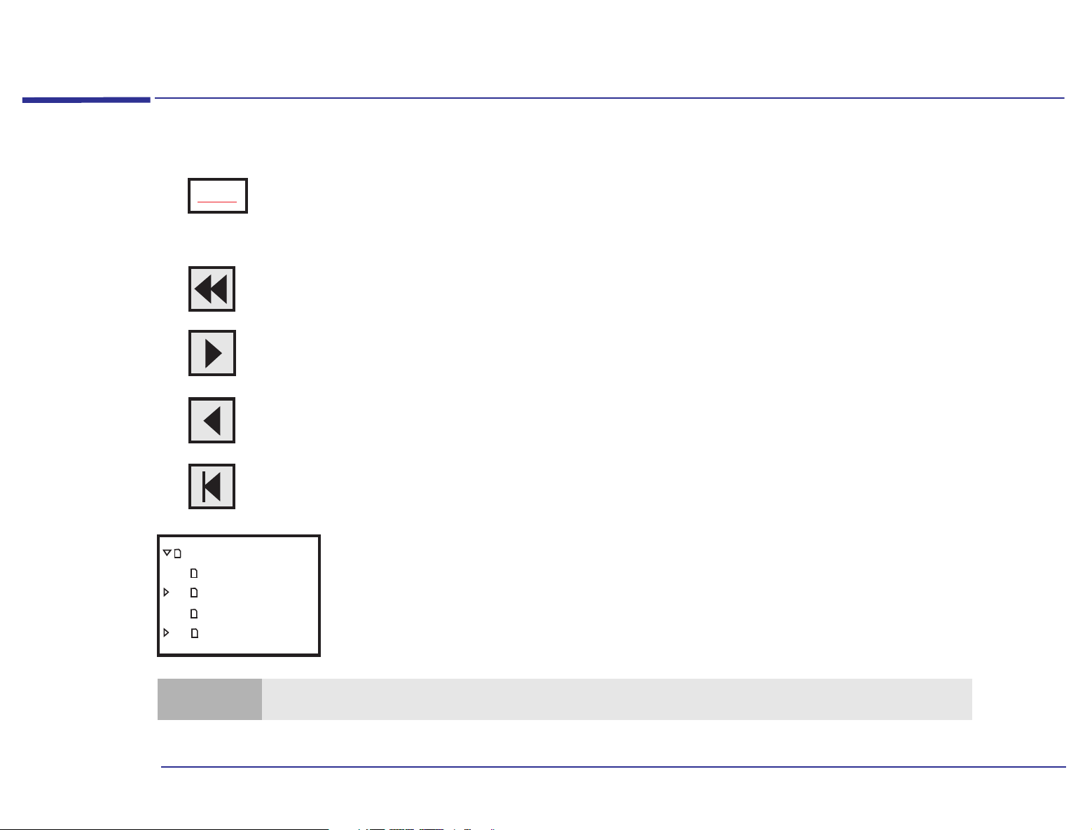
Click underlined red text to go to the topic indicated. Underlined red text is text that is “linked”
Topic
Click the Go Back button in the toolbar to go back to your previous place in the guide.
Click the Next Page button in the toolbar to go to the next page in the guide.
Click the Previous Page button in the toolbar to go to the previous page in the guide.
to another topic in the guide.
How To Use This Online Guide
Upgrade Guide
How to use this
Notice
Contents
Why Upgrade?
Note
Click the First Page button in the toolbar to go to the opening screen of the guide.
Click a bookmark name (to the left of the screen) to go to the topic corresponding to that
bookmark. Click the small triangle to the left of the bookmark to hide or show subordinate
bookmarks.
You can print this book; you can only print it in landscape format.
2
Page 3

Notice
Notice
The information contained in this document is subject to change without notice.
Hewlett-Packard makes no warranty of any kind with regard to this material, including, but not limited to, the implied
warranties of merchantability and fitness for a particular purpose. Hewlett-Packard shall not be liable for errors contained
herein or for incidental or consequential damages in connection with the furnishing, performance, or use of this material.
This document contains proprietary information that is protected by copyright. All rights are reserved. No part of this
document may be photocopied, reproduced, or translated to another language without the prior written consent of
Hewlett-Packard Company.
Microsoft®, MS-DOS® and Windows® are U.S. registered trademarks of Microsoft Corporation.
Hewlett-Packard France
Grenoble Personal Computer Division
Technical Marketing
38053 Grenoble Cedex 9
France
1997 Hewlett-Packard Company
3
Page 4

Associated Documentation
Associated Documentation
The following HP publications will also be useful to you.
• Advanced Setup Guide - online book giving technical specifications, and setup and configuration information for your
computer.
• Getting Support - paper book explaining how to obtain HP support. The book also contains safety and warranty
information.
• Questions & Answers - paper document that answers the most commonly asked questions.
• Learning About Your HP PC - online help giving information about your computer.
For a list of available documentation, double-click on the icon on the desktop or press the information key on
your (enhanced) keyboard.
If your computer is up and running but you are experiencing problems, refer to the online support center (see page 5
).
4
Page 5

HP Centers
HP Centers
Double-click on the icon on the desktop, or click on the start menu and then HP Centers, or press the key
on your keyboard, to open the HP Centers window.
Once you have opened the HP Centers window, you can access and use the following centers:
• Communications - communicate easily with the outside world
enable/disable fax reception, set up your answering machine, dial a phone number, and listen to your voice messages.
1
. You can set up your fax program, send a fax,
• Data Protection - make sure your data is secure and protected. You can protect your PC from viruses, back up your
data, maintain your hard disk (for example, scan it for errors), and restrict access to your PC.
• Network - share and access local network resources
modems, CD-ROM drives, Internet connections, and so on.
2
. You can easily share and access printers, folders and files, fax
• Welcome - discover what you can do with your PC and how to personalize it. You can register your PC, check your PC
settings, follow a PC tour, and see what documentation is available to you.
• Support - solve computer problems with the support tools and services provided by HP. You can diagnose hardware
problems, recover software applications that were preinstalled on your PC, access HP online support services, and run
Windows 95 troubleshooting tools.
1. Communications features are only available on communications models.
2. To use a local area network (LAN), you need to install a network card and software.
5
Page 6

HP Centers
6
Page 7

Contents
1 Why Upgrade?
How To Use This Online Guide. . . . . . . . . . . . . . . . . . . . . . . . . . . . . . . . . . . . . . . . . . . . . . . . . . . . . . . . . . . . . . . 2
Notice. . . . . . . . . . . . . . . . . . . . . . . . . . . . . . . . . . . . . . . . . . . . . . . . . . . . . . . . . . . . . . . . . . . . . . . . . . . . . . . . . . . . 3
Associated Documentation . . . . . . . . . . . . . . . . . . . . . . . . . . . . . . . . . . . . . . . . . . . . . . . . . . . . . . . . . . . . . . . . . . 4
HP Centers. . . . . . . . . . . . . . . . . . . . . . . . . . . . . . . . . . . . . . . . . . . . . . . . . . . . . . . . . . . . . . . . . . . . . . . . . . . . . . . . 5
Upgrading Your HP PC. . . . . . . . . . . . . . . . . . . . . . . . . . . . . . . . . . . . . . . . . . . . . . . . . . . . . . . . . . . . . . . . . . . . . 10
Upgrading the Main Memory. . . . . . . . . . . . . . . . . . . . . . . . . . . . . . . . . . . . . . . . . . . . . . . . . . . . . . . . . . . . . . . . 12
Upgrading the Video Memory . . . . . . . . . . . . . . . . . . . . . . . . . . . . . . . . . . . . . . . . . . . . . . . . . . . . . . . . . . . . . . . 13
Installing Expansion Cards . . . . . . . . . . . . . . . . . . . . . . . . . . . . . . . . . . . . . . . . . . . . . . . . . . . . . . . . . . . . . . . . . 14
Installing Storage Devices . . . . . . . . . . . . . . . . . . . . . . . . . . . . . . . . . . . . . . . . . . . . . . . . . . . . . . . . . . . . . . . . . . 15
Upgrading the Processor . . . . . . . . . . . . . . . . . . . . . . . . . . . . . . . . . . . . . . . . . . . . . . . . . . . . . . . . . . . . . . . . . . . 16
Upgrading the BIOS . . . . . . . . . . . . . . . . . . . . . . . . . . . . . . . . . . . . . . . . . . . . . . . . . . . . . . . . . . . . . . . . . . . . . . . 17
2 Installing Accessories in Your Computer
Supported HP Accessories . . . . . . . . . . . . . . . . . . . . . . . . . . . . . . . . . . . . . . . . . . . . . . . . . . . . . . . . . . . . . . . . . 20
7
Page 8

System Board Jumpers and Switches . . . . . . . . . . . . . . . . . . . . . . . . . . . . . . . . . . . . . . . . . . . . . . . . . . . . . 21
Backing Up Your Files. . . . . . . . . . . . . . . . . . . . . . . . . . . . . . . . . . . . . . . . . . . . . . . . . . . . . . . . . . . . . . . . . . . . . 22
Removing and Replacing the Cover . . . . . . . . . . . . . . . . . . . . . . . . . . . . . . . . . . . . . . . . . . . . . . . . . . . . . . . . . 23
Installing Main Memory . . . . . . . . . . . . . . . . . . . . . . . . . . . . . . . . . . . . . . . . . . . . . . . . . . . . . . . . . . . . . . . . . . . 27
Installing Video Memory . . . . . . . . . . . . . . . . . . . . . . . . . . . . . . . . . . . . . . . . . . . . . . . . . . . . . . . . . . . . . . . . . . . 30
Installing Video Memory on the System Board . . . . . . . . . . . . . . . . . . . . . . . . . . . . . . . . . . . . . . . . . . . . . 31
Installing Expansion Cards. . . . . . . . . . . . . . . . . . . . . . . . . . . . . . . . . . . . . . . . . . . . . . . . . . . . . . . . . . . . . . . . . 33
Installing an Expansion Card . . . . . . . . . . . . . . . . . . . . . . . . . . . . . . . . . . . . . . . . . . . . . . . . . . . . . . . . . . . 34
Installing a Network Card . . . . . . . . . . . . . . . . . . . . . . . . . . . . . . . . . . . . . . . . . . . . . . . . . . . . . . . . . . . . . . 39
Removing an Expansion Card . . . . . . . . . . . . . . . . . . . . . . . . . . . . . . . . . . . . . . . . . . . . . . . . . . . . . . . . . . . 41
Installing Storage Devices . . . . . . . . . . . . . . . . . . . . . . . . . . . . . . . . . . . . . . . . . . . . . . . . . . . . . . . . . . . . . . . . . 45
Installing an Additional Hard Disk Drive . . . . . . . . . . . . . . . . . . . . . . . . . . . . . . . . . . . . . . . . . . . . . . . . . . 49
Installing a Floppy Disk Drive, CD-ROM Drive, Zip Drive, or Tape Drive . . . . . . . . . . . . . . . . . . . . . . . . 52
Installing a Processor Upgrade . . . . . . . . . . . . . . . . . . . . . . . . . . . . . . . . . . . . . . . . . . . . . . . . . . . . . . . . . . . . . 56
Changing the Battery. . . . . . . . . . . . . . . . . . . . . . . . . . . . . . . . . . . . . . . . . . . . . . . . . . . . . . . . . . . . . . . . . . . . . . 61
Index . . . . . . . . . . . . . . . . . . . . . . . . . . . . . . . . . . . . . . . . . . . . . . . . . . . . . . . . . . . . . . . . . . . . . . . . .63
8
Page 9

1
Why Upgrade?
Page 10

1 Why Upgrade?
Upgrading Your HP PC
Upgrading Your HP PC
Your computer uses some of the latest hardware technology to achieve outstanding performance. If required,
performance can be even further enhanced thanks to this computer’s upgradeable design.
Main Memory Main memory is the workspace of the computer. It is in this workspace that the processor stores all work in progress. You
can increase the size of the computer’s workspace by adding more main memory.
To find out more about upgrading the main memory, refer to “Upgrading the Main Memory” on page 12.
Video Memory Video memory stores everything that you see on your computer screen. In order to provide a solid image on the screen,
the screen image has to be continually refreshed. The computer’s graphics system uses the image stored in video memory
to refresh the screen.
Increasing the amount of video memory enables higher screen resolutions, higher refresh rates and many more colors for
existing resolutions, enhancing and accelerating graphics-intensive applications.
To find out more about upgrading the video memory, refer to “Upgrading the Video Memory” on page 13
.
Expansion Cards An expansion card, or accessory board, is a component that usually adds some specialized function to a computer. For
example, installing a network card can, in conjunction with the necessary software and cables, connect a computer to a
network.
To find out more about installing expansion cards, refer to “Installing Expansion Cards” on page 14
.
Storage Devices A storage device is a device that stores software (for example, applications, programs, the operating system, data, and so
on). Hard disk drives, CD-ROM drives, tape drives, Zip drives, and floppy disk drives are all examples of storage devices.
To find out more about installing storage devices, refer to “Installing Storage Devices” on page 15.
10
Page 11

1 Why Upgrade?
Upgrading Your HP PC
Processor The processor is the primary computational chip inside the computer. It can be thought of as the computer’s brain. It may
be upgraded to provide more power for processor-intensive applications.
To find out more about installing a processor upgrade, refer to “Upgrading the Processor” on page 16.
11
Page 12

Upgrading the Main Memory
1 Why Upgrade?
Upgrading the Main Memory
How Much Main
Memory Does My
Computer Have?
Why Add More Main
Memory?
How Much Main
Memory Can I Add?
Will Adding Memory
Always Improve
The amount of main memory that your computer has depends on the particular model that you have. To see how much
main memory is installed, restart your computer and press when Press <F2> to enter SETUP is displayed at
the bottom of the screen. This displays a series of screens that show the computer’s configuration. The amount of main
memory installed is shown on the Main screen in the Memory fields.
By adding more memory you can significantly improve the computer’s performance. If your computer does not have
enough memory, it uses hard disk space as virtual memory which allows large applications to execute even though the
physical memory is not sufficient. Virtual memory, however, is approximately 200 times slower than main memory.
The amount of main memory your computer requires depends on the operating system and the applications you use. You
will need more memory if you use memory-hungry applications (for example, image processing and desktop publishing
applications) or if you run several applications at the same time.
Your computer is capable of supporting up to 128 MB of main memory, using four memory module sockets on the system
board.
Adding memory will not always improve performance. If your computer has sufficient memory, installing extra memory
will not improve performance.
Performance?
For instructions on how to add main memory modules, refer to “Installing Main Memory” on page 27.
12
Page 13

Upgrading the Video Memory
1 Why Upgrade?
Upgrading the Video Memory
How Does Video
Memory Work?
How Much Video
Memory Does My
Computer Have?
Why Increase the
Amount of Video
Memory?
How Much Video
Memory Can I Add?
The image on the screen is made up of tiny dots called pixels. Each pixel has a color, and every color is represented by a
value. Video memory stores the color value of every pixel.
The screen resolution determines how many pixels make up a displayed screen. The number of pixels required is
typically very large (for example, 300,000 pixels for a standard VGA screen with a resolution of 640
The amount of video memory that your computer has depends on the particular model that you have. You may have 1 MB
or 2 MB of video memory installed on the system board. To find out how much video memory is installed, from Windows
95 select the Display icon from the Control Panel and click the Settings tab, then select the Advanced Properties button.
Increasing your display resolution will increase the total number of pixels needed to define an entire screen. Similarly,
increasing the number of displayable colors will increase the amount of data required to display the pixels. Increasing
either of these parameters will increase your requirement for video memory.
More video memory makes it possible to obtain higher screen resolutions, higher refresh rates (the frequency at which
the screen’s horizontal lines are recharged), and many more colors for existing resolutions.
If your computer has 1 MB of video memory on the system board, you can increase it to 2 MB. To find out how much video
memory is installed, from Windows 95 select the Display icon from the Control Panel and click the Settings tab, then select
the Advanced Properties button.
× 480).
For instructions on how to upgrade the video memory, refer to “Installing Video Memory” on page 30
.
13
Page 14
Installing Expansion Cards
1 Why Upgrade?
Installing Expansion Cards
What Is an
Expansion Card?
How Many
Expansion Cards Do
I Have?
Why Add More
Expansion Cards?
Expansion cards have sockets at one end which, once the card is installed, are accessible from the back of the computer.
There are two types of expansion cards that you can install in your computer: Industry-Standard Architecture (ISA)
cards and Peripheral Component Interconnect (PCI) cards. PCI cards use the computer’s PCI bus (information
pathway), and ISA cards use the computer’s ISA bus. The PCI bus is faster than the ISA bus.
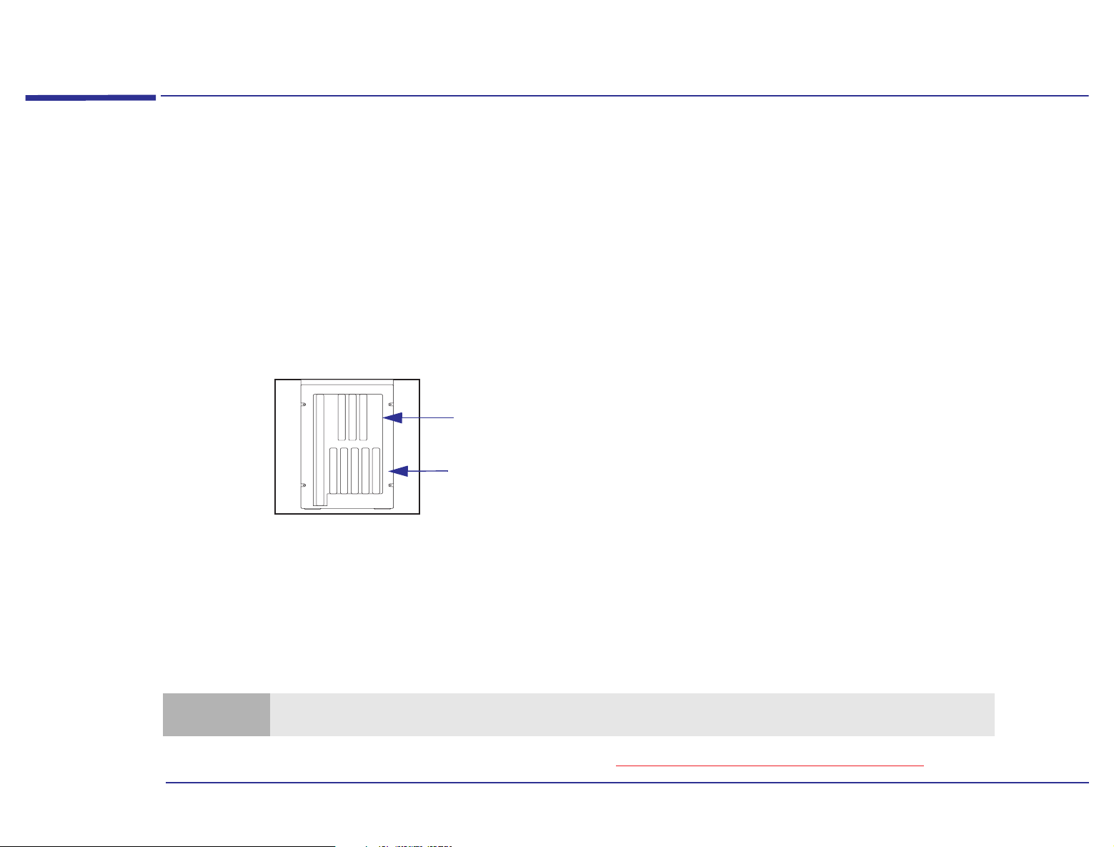
The number of expansion cards that your computer has depends on the particular model that you have. You can tell how
many cards are installed by looking at the back of your computer and counting the number of slots that are occupied. This
is the number of expansion cards that are installed.
These three upper expansion
card slots are not available.
Expansion card slots
Back of computer
Adding more expansion cards will increase the capability of your computer.
How Many
Expansion Cards Can
I Install?
Your computer supports up to five cards.
Note
For instructions on how to add an expansion card, refer to “Installing Expansion Cards” on page 33
The three upper expansion card slots cannot be used.
.
14
Page 15

Installing Storage Devices
1 Why Upgrade?
Installing Storage Devices
How Many Storage
Devices Does My
Computer Have?
Why Add More
Storage Devices?
How Many Storage
Devices Can I Add?
Your computer is supplied with one hard disk drive mounted on an internal shelf, and one front-access 3.5-inch floppy
disk drive. There may also be a CD-ROM drive installed.
Adding additional storage devices is often necessary when, for example, a large amount of information needs to be
frequently accessed.
The number of storage devices that you can add to your computer is determined by the number of mounting shelves that
are unused and by the number of storage device interface channels that are unused.
In addition to the 3.5-inch floppy disk drive and a hard disk drive, your computer has four front-access device shelves
available for new drives (note that one of these shelves may already be occupied by a CD-ROM drive). There is also one
internal shelf available, which may be used for an additional hard disk drive.
The on-system board electronics have a total of six interface channels that can support up to six storage devices—two
FDD (Floppy Disk Drive) devices and four IDE (Integrated Drive Electronics) devices.
Note
You can install a non-IDE device such as a SCSI drive but you will also need to install an interface card and software
for it.
For instructions on how to add a storage device, refer to “Installing Storage Devices” on page 45
.
15
Page 16

Upgrading the Processor
1 Why Upgrade?
Upgrading the Processor
What Is the
Processor?
Why Upgrade the
Processor?
What Is the Fastest
Processor I Can
Install?
The processor communicates with other parts of the computer via three buses (information pathways):
• the processor’s local bus
• the PCI (Peripheral Component Interconnect) bus
• the ISA (Industry-Standard Architecture) bus
Each bus connects functional components of the computer which have similar data-handling requirements. The three
buses operate at different speeds and are connected via bridges. (A bridge converts data from one bus into a format that
is suitable for the destination bus.)
The speed at which the processor can perform tasks is determined by the processor’s internal speed; the faster the
internal speed, the faster tasks can be performed. Replacing the processor by one with a faster internal speed will improve
the performance of your computer.
New, faster processors are being developed all the time. Check with your HP-authorized support agent or reseller to find
out what is the fastest processor that you can install in your computer.
For instructions on how to install a processor upgrade, refer to “Installing a Processor Upgrade” on page 56.
16
Page 17

1 Why Upgrade?
Upgrading the BIOS
Upgrading the BIOS
What Is the BIOS? The BIOS (Basic Input/Output System) is the set of programs that automates the computer’s components. The BIOS is
stored in a chip on the system board.
The BIOS simplifies the instructions necessary for the operating system and the programs running on your computer,
thereby reducing their size and making the system more efficient.
Why Upgrade the
BIOS?
How Do I Upgrade
the BIOS?
Hewlett-Packard are continually improving the BIOS in their computers, introducing new features and making them more
efficient. You can therefore keep your own computer up-to-date by upgrading the BIOS.
To upgrade your system BIOS, download the appropriate BIOS utility from our Web support site.
World-Wide Web URL http://www.hp.com/go/smallbizsupport
17
Page 18

1 Why Upgrade?
Upgrading the BIOS
18
Page 19

2
Installing Accessories in Your Computer
Page 20
2 Installing Accessories in Your Computer
Supported HP Accessories
Supported HP Accessories
This chapter describes how to install memory, storage devices (such as a hard disk drive, floppy disk drive, CD-ROM
drive, Zip drive, or tape drive), and expansion cards in your computer.
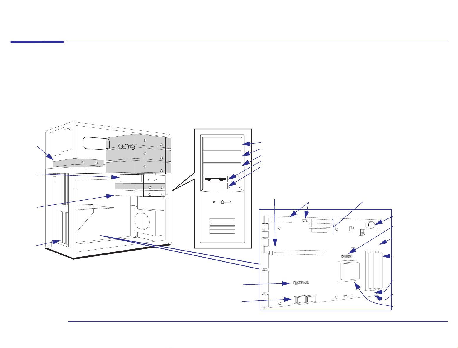
Your computer might have one or more expansion cards preinstalled. Some of the additional accessories that you can
add to your computer are shown here.
Second 3.5inch Hard
Disk Drive
bay
Preinstalled
3.5-inch
Floppy Disk
Drive
(Drive A)
Preinstalled
3.5-inch
Hard Disk
Drive
(Drive C)
Expansion
Cards
For example,
a LAN card
† Sockets are shown filled. Empty sockets indicate that an upgrade is
possible.
Front Bezel
VESA Feature Connector
Video Memory Upgrade
Modules
†
1 MB (2 × 512 KB modules)
Front-Access Device Shelves
· IDE CD-ROM Drive bay
· Tape or Zip Drive bay
· 5.25-inch Floppy or Hard Disk Drive bay
· Preinstalled 3.5-inch Floppy Disk Drive (Drive A)
· Second 3.5-inch Floppy Disk Drive bay
Backplane connector
Power Connectors
(to power supply)
JP5
System Board
JP7
IDE and Floppy Drive
Connectors
System Board
Configuration Jumpers
Backup Battery
Front Bezel Switch
JP37
DCBA
Connector
Memory Module Order:
Left to right: A, B, C, D
Main Memory Upgrade
Modules
8 MB, 16 MB or 32 MB
Front Bezel Fan
Connector
Processor Fan
Connector
Processor Upgrade
†
20
Page 21

Contact your HP-authorized support agent or reseller for HP accessory part numbers.
2 Installing Accessories in Your Computer
Supported HP Accessories
Warning
For your safety, never remove the computer’s cover without first removing the power cord and any connection to a
telecommunications network. Always replace the cover before turning on the computer.
System Board Jumpers and Switches
Power Connectors
(to power supply)
Backplane
Connector
J1
Rear Panel
Connectors
J30
Secondary IDE Connector
Primary IDE Connector
Floppy Disk Drive Connector
J12
J15
J20
JP6
1
2
3
JP7
3
5
1
3
5
7
9
J37
21
4
6
Clear CMOS
Backup Battery
2
4
6
8
10
Processor
Voltage Selection
Clock Ratio
Front Bezel Switch
Connector
Main Memory Module
and Sockets
VESA Feature Connector
Video Memory
Upgrade Sockets
Processor Fan
Connector
ABCD
Processor Socket
Front Bezel Fan
Connector
21
Page 22

Backing Up Your Files
2 Installing Accessories in Your Computer
Backing Up Your Files
Caution
For further information about backing up your files, refer to the online data protection center.
You should always make sure you have performed a backup of your files before you install components inside your
computer.
22
Page 23

2 Installing Accessories in Your Computer
Removing and Replacing the Cover
Removing and Replacing the Cover
You need to remove the computer’s cover to install accessories or to gain access to the system configuration jumpers.
Removing the Cover 1 Turn off the computer and display, and disconnect all power supply cords and any telecommunications cables.
23
Page 24

2 Remove the four screws from the back of the computer.
3 Pull the cover back 1.5 cm. Then lift the cover completely off.
2 Installing Accessories in Your Computer
Removing and Replacing the Cover
1.5 cm
24
Page 25

2 Installing Accessories in Your Computer
Removing and Replacing the Cover
Replacing the Cover 1 Check that you have installed all your accessories and that internal cables are properly connected and safely routed
(for example, check that they will not interfere with the cover when it is replaced).
2 Lower the cover onto the computer. Position the cover so that there is a 1.5 cm gap between the front edge of the cover
and the front bezel.
1.5 cm
25
Page 26

2 Installing Accessories in Your Computer
Removing and Replacing the Cover
3 While holding the cover as shown, lift the cover up approximately 1 cm until a ‘pop’ is heard, then lower the cover. Metal
tabs at the bottom of the cover should now be hooked onto the chassis of the computer.
1cm
4 Push the cover forward until it meets the front bezel. Secure the cover in place by replacing the four screws on the rear
panel.
5 Reconnect the power supply cords and any telecommunications cables. Turn on the display and computer.
26
Page 27

Installing Main Memory
2 Installing Accessories in Your Computer
Installing Main Memory
Installing Main
Memory Modules
Caution
Your computer is supplied with main memory. If you need more main memory to run your applications, you can increase
the memory up to 128 MB.
Main memory is available in modules of 8 MB, 16 MB or 32 MB.
Note
1 Remove the computer’s cover (refer to “Removing the Cover” on page 23).
2 Align the new memory module with the socket. Make sure that the notch in the module is aligned in the socket, as
shown in the following diagram.
Static electricity can damage electronic components. Turn off all equipment. Don’t let your clothes touch the
accessory. To equalize the static electricity, rest the accessory bag on top of the computer while you are removing
the accessory from the bag. Handle the accessory as little as possible and with care.
You must install memory modules in pairs which are the same size.
Notch
27
Page 28

2 Installing Accessories in Your Computer
Installing Main Memory
3 Slide the memory module into the socket at an angle of about 45° (that is, the leading edge of the module is pointing
slightly to the back of the computer). Firmly press the module completely into the socket.
4 Pivot the memory module until it clicks into the socket retaining clips.
Step 3 Step 4
System Board
B
A
Retaining Clips
D
C
A
D
C
B
For best performance, fill
bank “A” and “B” first, then
fill bank “C”, and “D”.
5 Repeat this procedure to install each of the new memory modules.
6 Install any other accessories before replacing the cover, and reconnecting the power supply cords and any
telecommunications cables.
7 Turn on the display, let it warm up, and then turn on the computer. Press when Press <F2> to enter SETUP
is displayed at the bottom of the screen. This displays a series of screens that show the computer’s configuration details.
Check that the new memory is recognized (it is shown on the Main screen in the Memory fields).
28
Page 29

2 Installing Accessories in Your Computer
Installing Main Memory
Troubleshooting ❒ If the new memory is not recognized, check that you have correctly followed the installation procedure described
above.
❒ If there are any errors reported during the computer’s startup routine, press to view the error(s) and take any
necessary action.
❒ If you cannot start your computer properly, remove the memory and try starting your computer again. If the computer
now starts OK, there may be a problem with the new memory.
❒ If you experience any other problems as a result of the upgrade, refer to the online support center.
Removing a
Memory Module
If you need to remove a main memory module, release the retaining clips at both ends of the socket and lift the module
up and then out.
a. Release the
retaining clips
b. Lift the module up,
then out
29
Page 30

Installing Video Memory
2 Installing Accessories in Your Computer
Installing Video Memory
Caution
You may need to install more video memory to display more colors, for higher resolutions, or for increased speed. The
system board can accept a maximum of 2 MB of video memory. Depending on your model, your computer may already
have 2 MB of video memory on the system board, in which case your video memory cannot be upgraded. Otherwise, your
computer is supplied with 1 MB of video memory on the system board, which can be increased to 2 MB (using an
upgrade module available from your HP-authorized support agent or reseller).
Static electricity can damage electronic components. Turn off all equipment. Don’t let your clothes touch the
accessory. To equalize the static electricity, rest the accessory bag on top of the computer while you are removing
the accessory from the bag. Handle the accessory as little as possible and with care.
30
Page 31

2 Installing Accessories in Your Computer
Installing Video Memory
Installing Video Memory on the System Board
1 Remove the computer’s cover (refer to “Removing the Cover” on page 23).
2 Align the video memory module directly over the socket, making sure that the tapered end of the module is facing the
rear of the computer.
The small circle on
the module should
match up with a
small arrow on the
socket.
System Board
Arrow
Circle
3 Firmly press the memory module completely into the socket.
4 Repeat steps 2 and 3 for the second memory module.
5 Install any other accessories before replacing the cover and reconnecting the power supply cords and any
telecommunications cables.
6 Turn on the display, let it warm up, and then turn on the computer.
7 Once your computer is up and running, use the Display icon in the Windows 95 Control Panel (accessible from the
Windows 95 START | Settings | Control Panel | Display | Settings) to change the video resolution
and the number of colors displayed.
31
Page 32

2 Installing Accessories in Your Computer
Installing Video Memory
Troubleshooting ❒ If the new memory is not recognized, check that you have correctly followed the installation procedure described
above.
❒ If there are any errors reported during the computer’s startup routine, press to view the error(s) and take any
necessary action.
❒ If you cannot start your computer properly, remove the memory and try starting your computer again. If the computer
now starts OK, there may be a problem with the new memory.
❒ If you experience any other problems as a result of the upgrade, refer to the online support center.
Removing Video
Memory
If you need to remove a video memory module, a special tool (part number 5041-2553, available from your HP-authorized
support agent or reseller) is required. Insert this tool into the notched ends of the module and lever the module out.
32
Page 33

2 Installing Accessories in Your Computer
Installing Expansion Cards
Installing Expansion Cards
Your computer has five expansion card slots. These slots allow you to install expansion cards as follows:
• Slot 1 (next to the system board) can be used for a short 16-bit ISA card (16 cm/6.3-inch maximum length). If your
computer is equipped with an audio card, it is located in this slot.
• Slot 2 can be used for a short 16-bit ISA card (16 cm/6.3-inch maximum length).
• Slot 3 can be used for a full-length 16-bit ISA or a 32-bit PCI card.
• Slots 4 and 5 can be used for 32-bit PCI cards.
Note
The Windows 95 operating system can automatically recognize and configure many expansion cards that you may want
to install in your computer. With other cards, you will need to run the Windows 95 Add New Hardware wizard to help
Windows 95 to recognize the card.
You must physically install the card before you run the wizard. Refer to your Windows 95 documentation and online help
for more information about using the wizard.
The settings selected by Windows 95 may be different from those recommended by the card’s manufacturer. In this case,
the card’s jumper settings and driver options might need to be altered. Refer to the manual supplied with the card for
more information.
You may already have one or more expansion cards installed and configured in your
computer.
33
Page 34

Installing an Expansion Card
2 Installing Accessories in Your Computer
Installing Expansion Cards
Caution
Static electricity can damage electronic components. Turn off all equipment. Don’t let your clothes touch the
accessory. To equalize the static electricity, rest the accessory bag on top of the computer while you are removing
the accessory from the bag. Handle the accessory as little as possible and with care.
1 Remove the computer’s cover (refer to “Removing the Cover” on page 23).
2 On a table top turn the computer on to its side, with the system board closest to the surface of the table top.
3 Disconnect the power, storage device, and front bezel fan connectors shown below from the system board connectors.
Secondary IDE Connector
Disks E and F
Primary IDE Connector
Disks C and D
Floppy Disk Connector
Disks A and B
System Board
PS1
Power Connectors
(to power supply unit)
PS2
CD-ROM
HDD
FDD
System Board
Front Bezel
Fan Connector
Processor
Fan Connector
System Board
34
Page 35

2 Installing Accessories in Your Computer
Installing Expansion Cards
4 Slide the system board drawer out of the computer chassis as far as the remaining connected cables permit.
5 Find a free expansion card slot with the correct type of connector (PCI or ISA, refer to “Installing Expansion Cards” on
page 33). Some cards may have preferred locations, in which case special installation instructions should be detailed
in their manuals.
6 Unscrew and remove the expansion card slot cover. Store it in a safe place. If the slot cover is tight, loosen the screws
on the adjacent slots.
35
Page 36

2 Installing Accessories in Your Computer
Installing Expansion Cards
7 Hold the card horizontally with the card’s connector pointing towards the slot’s connector. Slide the card into the slot.
Do not bend the card.
Step 6
Step 7
8 Ensure that the card’s connector engages completely with the slot’s connector and does not touch components on other
cards.
36
Page 37

2 Installing Accessories in Your Computer
Installing Expansion Cards
9 Secure the card by replacing the slot cover screw. If you loosened the screws on adjacent slots, remember to tighten
them.
10 Reconnect the power, storage device, and front bezel fan connectors to the system board connectors. The connectors
are shaped to fit one way only (they have indexing pins). Slide the system board drawer back into the computer chassis.
PS
PS2
PS1
Indexing Pin
System Board
11 If you are installing a VESA-standard video adapter card that uses the video controller, connect the expansion card’s
cable to the VESA Feature Connector on the system board (refer to “Supported HP Accessories” on page 20
).
37
Page 38

2 Installing Accessories in Your Computer
Installing Expansion Cards
12 Install any other accessories before replacing the cover and reconnecting the power cords and any telecommunications
cables. Turn on the display and computer.
13 If you have just installed a Plug and Play expansion card, Windows 95 is able to recognize and configure the card
automatically. The New Hardware Found dialog box is displayed while Windows 95 loads the necessary driver(s).
If you have just installed a non-Plug and Play expansion card, run the Windows 95 Add New Hardware wizard
(accessible from the Windows 95 STAR T | Settings | Co ntrol Panel) to help Windows 95 to recognize and
configure the card.
Troubleshooting ❒ If the new card is not recognized, check that you have correctly followed the installation procedure described above.
❒ If there are any errors reported during the computer’s startup routine, press to view the error(s) and take any
necessary action.
❒ If you find that files on your storage devices no longer correspond to the correct drive letter (for example the content
of disk C is now shown as being on disk E), you have reversed the connection of the primary and secondary IDE cables
on the system board. Remove the computer’s cover (refer to “Removing the Cover” on page 23
connection of the IDE cable as shown below.
) and reverse the
CD-ROM
HDD
FDD
System Board
Secondary IDE Connector
Disks E and F
Primary IDE Connector
Disks C and D
Floppy disk Connector
Disks A and B
Reverse the cable connection
to these two connectors
❒ If you cannot start your computer properly, remove the card and try starting your computer again. If the computer now
starts OK, there may be a problem with the new card.
❒ If you experience any other problems as a result of the upgrade, refer to the online support center.
38
Page 39

2 Installing Accessories in Your Computer
Installing Expansion Cards
Installing a Network Card
This section contains additional expansion card information describing how to install a “10BaseT” type of network card
such as the one supplied in the HP network kit.
Caution
Static electricity can damage electronic components. Turn off all equipment. Don’t let your clothes touch the
accessory. To equalize the static electricity, rest the accessory bag on top of the computer while you are removing
the accessory from the bag. Handle the accessory as little as possible and with care.
Installing the Card 1 Install the network card as described in steps 1 to 10 of “Installing an Expansion Card” on page 34.
2 Do not turn on the computer yet as this may cause an error message to be displayed indicating that there is a problem
with the network card—which is not true.
3 Connect one end of the network cable to the back of the network card, and the other end of the cable to the network
hub.
Network Hub
Network Card
Turning On the
Computer
4 Turn on the display and computer. Shortly after Windows 95 starts, the New Hardware Found - PCI Ethernet Controller
dialog box appears.
39
Page 40

2 Installing Accessories in Your Computer
Installing Expansion Cards
If Windows 95 finds the driver for the network card in its list of pre-loaded drivers, Windows 95 loads the driver. If this
is the case, go to step 5.
If Windows 95 does not find the correct driver, it displays the following choices for you to select:
• Windows default driver.
(Shaded if the card is not known by Windows 95). If this option is available, select it.
• Driver from disk provided by the manufacturer.
If a Windows default driver is not available, and you have a driver disk, select this option. You then need to insert
the disk and click the OK button.
• Do not install a driver. Windows will not prompt you again.
In this case, the card will be installed but it will not work.
• Select from a list of alternative drivers.
Note
If at any time, Windows 95 asks for the disk or the directory where its master files are located, either type
c:\windows\options\cabs, or insert your Windows 95 CD-ROM in the CD-ROM drive and type
E:\win95 (assuming that E: is the CD-ROM drive letter).
Network Settings 5 In the Network Identification dialog box, enter a Computer name and a Workgroup.
The computer name must be a unique name within a workgroup. The workgroup name does not have to be unique
(HP recommends that all the PCs in an office have the same workgroup name).
Also, you can optionally enter some free-format text in the Computer Description field.
6 If you do not want your computer to appear on other computer lists when people browse the network, click the Close
button and go to step 9.
40
Page 41

2 Installing Accessories in Your Computer
Installing Expansion Cards
Otherwise, select the Configuration tab at the top of the dialog box and check that you can see the following network
components.
Restarting the
Computer
• Client for Microsoft
®
Networks
• Client for NetWare Networks
• Your LAN card adapter name
• IPX/SPX-compatible Protocol
• NetBEUI
7 In the Primary Network Logon drop-down list box, select Client for Microsoft Networks.
8 Click the File and Print Sharing button. Select the two check boxes and click the OK button.
9 Shut down and then restart the computer.
10 When Windows 95 prompts you for a user name and password, enter a new user name and password. Re-enter the
password to confirm it, and click the OK button.
If you experience any problems as a result of the upgrade, refer to the online support center.
Removing an Expansion Card
You might need to remove an expansion card to install a component on it, or to improve access to components on the
system board.
Removing a Card 1 Remove the computer’s cover (refer to “Removing the Cover” on page 23).
2 On a table top turn the computer on to its side, with the system board will be closest to the surface of the table top.
41
Page 42

2 Installing Accessories in Your Computer
Installing Expansion Cards
3 Disconnect the power, storage device, and front bezel fan connectors shown below from the system board connectors.
System Board
PS1
Power Connectors
(to power supply unit)
PS2
System Board
System Board
CD-ROM
HDD
FDD
Secondary IDE Connector
Disks E and F
Primary IDE Connector
Disks C and D
Floppy Disk Connector
Disks A and B
Processor Fan
Connector
Front Bezel
Fan Connector
42
Page 43

2 Installing Accessories in Your Computer
Installing Expansion Cards
4 Slide the system board drawer out of the computer chassis as far as the remaining connected cables permit.
5 Unscrew and remove the screw securing the card. Keep the screw.
6 Carefully remove the card from its connector, holding the card at each end by its top edge. If the card is tight, loosen
the screws on the adjacent slots. Do not bend the card. If you intend to replace the card later, note which connector it
is in.
43
Page 44

2 Installing Accessories in Your Computer
Installing Expansion Cards
7 With its components facing up, place the card on a clean, flat, solid, static-free surface. Handle the card by its edges.
8 Install any new accessories.
9 Replace the expansion card if necessary (refer to steps 7, 8, and 9 of “Installing an Expansion Card” on page 34
). If you
do not replace the card, remember to replace the slot cover.
10 Reconnect the power, storage device, and front bezel fan connectors to the system board connectors. The connectors
are shaped to fit one way only (they have indexing pins). Slide the system board drawer back into the computer chassis.
PS
PS2
PS1
Indexing Pin
System Board
11 Replace the cover. Reconnect the power cords and any telecommunications cables. Turn on the display and computer.
44
Page 45

2 Installing Accessories in Your Computer
Installing Storage Devices
Installing Storage Devices
You can install additional storage devices if, for example, you need extra storage space for your application software.
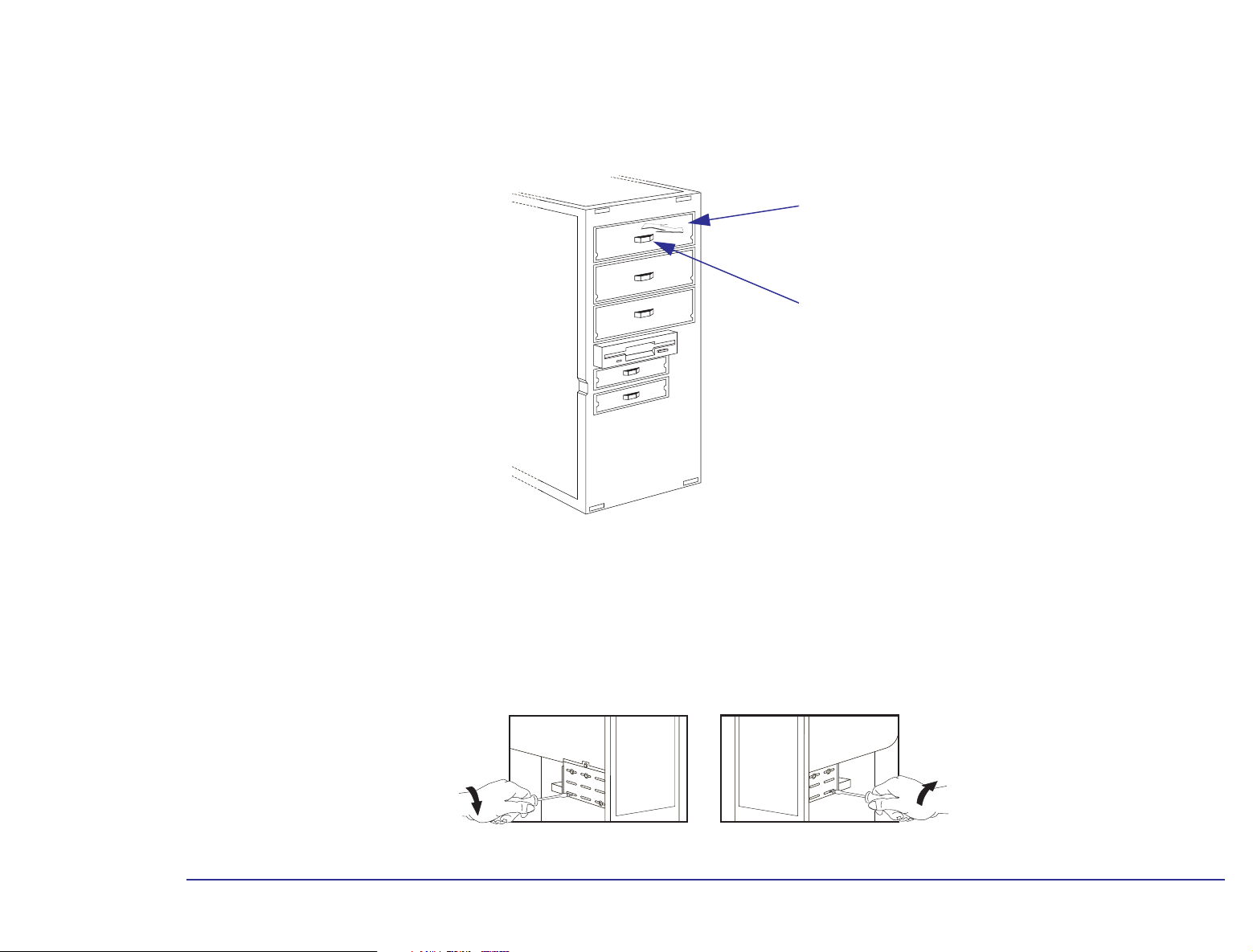
Your computer already has one hard disk drive installed in an internal front shelf. You can install another 3.5-inch hard
disk drive in the internal back shelf, beneath the power supply, or a 5.25-inch hard disk drive in the front lower 5.25-inch
storage device shelf.
Your computer has a 3.5-inch floppy disk drive installed in a front-access device shelf. Four more front-access device
shelves are available to install other drives (only three shelves are available if you already have a CD-ROM drive
installed).
Second 3.5inch Hard
Disk Drive
bay
Preinstalled
3.5-inch
Floppy Disk
Drive
(Drive A)
Preinstalled
3.5-inch
Hard Disk
Drive
(Drive C)
Note
Front-Access Device Shelves
· IDE CD-ROM Drive bay
· Tape or Zip Drive bay
· 5.25-inch Floppy or Hard Disk Drive bay
· Preinstalled 3.5-inch Floppy Disk Drive (Drive A)
· Second 3.5-inch Floppy Disk Drive bay
Front Bezel
Disk drives ordered from HP may be supplied with mounting rails. Remove all mounting rails from the drive, as your
computer does not need them.
45
Page 46

2 Installing Accessories in Your Computer
Installing Storage Devices
Your computer has the following cables which may be used by storage devices:
• A primary Enhanced IDE (Integrated Drive Electronics) hard disk drive cable with two connectors. This cable supports
up to two IDE hard disk drives, one of which is already connected to the drive C connector on this cable.
• A secondary Enhanced IDE drive cable with two connectors. If you already have a CD-ROM drive installed, it is
connected to the drive E connector on this cable. If you install a CD-ROM drive, or a third hard disk drive, or both,
connect it or them to this cable.
• A floppy disk drive cable. This supports up to two floppy disk drives (or one floppy disk drive and one tape drive). One
3.5-inch floppy disk drive is already connected to the drive A connector on this cable.
46
Page 47

2 Installing Accessories in Your Computer
Installing Storage Devices
System Board
Connectors
If you add a floppy disk drive, hard disk drive, CD-ROM drive, Zip drive, or tape drive, you need to connect it to power
and data cables. The connectors are shaped to fit one way only. The data cables are shown below.
Connectors for IDE
CD-ROM Drives, Zip
Drives, or IDE Hard
Disk Drives
Connectors for IDE Hard
Disk Drives
System Board
CD-ROM
HDD
FDD
Secondary IDE Connector
Disks E and F
Primary IDE Connector
Disks C and D
Floppy disk Connector
Disks A and B
Connectors for 3.5-inch Floppy
Disk Drives (some types) or Tape
Drives (some types)
Drive A
Drive B
Drive F
Drive E
Drive D
Drive C
Note
System Board
You may install a non-IDE storage device, but this requires a cable, an expansion card, and driver software. Contact
your HP-authorized support agent or reseller for information.
47
Page 48

2 Installing Accessories in Your Computer
Installing Storage Devices
The following table explains which connectors you should typically use when you install additional IDE devices.
Type of Storage
Device
One to four hard
disk drives
One CD-ROM drive 1. CD-ROM drive (not available if the third hard disk drive is installed—see above): Secondary IDE cable, drive E connector
One or two floppy
disk drives
One tape drive 1. Primary tape drive (not available if the second floppy disk drive is installed—see above): Floppy disk cable, drive B connector
One Zip drive 1. Zip drive (not available if the fourth hard drive is installed—see above): Secondary IDE cable, drive F connector
Note
1. Bootable hard disk drive:
2. Second hard disk drive:
3. Third hard disk drive (not available if a CD-ROM drive is installed):
4. Fourth hard disk drive (not available if a Zip drive is installed):
1. Primary floppy disk drive:
2. Second floppy disk drive (not available if the tape drive is installed):
If you install a hard disk drive and connect it to the cable that the CD-ROM drive is connected to, the hard disk drive
Device Connection
Connections to Data Cables
Primary IDE cable, drive C connector
Primary IDE cable, drive D connector
Primary IDE cable, drive E connector
Secondary IDE cable, drive F connector
Floppy disk cable, drive A connector
Floppy disk cable, drive B connector
must be connected to the first connector in the cable from the system board, not the last connector. If you have a
CD-ROM drive currently connected to the first connector, you must reconnect the CD-ROM drive to the last
connector of the cable, and then attach the new hard disk drive to the first connector.
48
Page 49

2 Installing Accessories in Your Computer
Installing Storage Devices
There are two different types of power connectors:
Power Connectors for Hard
Disk Drives, Tape Drives,
5.25-inch Floppy Disk Drives,
CD-ROM Drives, Zip Drives,
and 3.5-inch Floppy Disk
Drives (some types)
Some of the power connectors will be already connected to devices.
If you install a device that requires a different connector, the connector converter should be supplied with the device.
Power Connector for 3.5inch Floppy Disk Drive
(some types)
Installing an Additional Hard Disk Drive
Refer to the drive’s manual(s) to see if you must set jumpers or if there is a special installation procedure to follow.
Note
Installing the Drive 1 Remove the computer’s cover (refer to “Removing the Cover” on page 23).
If your new hard disk drive already has a mounting tray attached, you must remove it before you can install the drive
in your computer.
49
Page 50

2 Installing Accessories in Your Computer
Installing Storage Devices
2 Install the new hard disk drive in the computer:
• For a 3.5-inch hard disk drive – mount the new hard disk drive in the bay under the power supply unit at the rear of
the computer. Have the connectors of the new hard disk drive pointing towards the front of the computer.
• For a 5.25-inch hard disk drive – mount the new hard disk in the bottom 5.25-inch bay at the front of the computer.
Have the connectors of the new hard disk drive pointing towards the back of the computer.
3 Secure the drive to the computer using the four screws provided with the drive. Two screws must be inserted in each
side of the drive. Using screws other than those provided may cause damage to the device.
4 Connect the power and data cables to the rear of the drive. The power connector is shaped to fit one way only. Refer
to the drive’s manual(s) for the orientation of the data connector. Use the second to last connector on the hard disk
drive data cable. Refer to “System Board Connectors” on page 47
Data Cable
5 If the system board drawer was pulled-out, slide the system board drawer back into the computer chassis.
for an illustration of the cables and connectors.
Storage Device
Power Cable
50
Page 51

2 Installing Accessories in Your Computer
Installing Storage Devices
6 Install any other accessories before replacing the cover and reconnecting the power cords and any telecommunications
cables.
7 Turn on the display, let it warm up, and then turn on the computer. Press when Press <F2> to enter SETUP
is displayed at the bottom of the screen. This displays a series of screens that show the computer’s configuration details.
Check that the new drive is recognized (it is shown on the Main screen in the Primary / Secondary, Master /
Slave fields).
Before you can use the new hard disk drive, you will probably need to set up partitions and then format the drive. To
do this, restart your computer in MS-DOS mode, run fdisk to set up the partitions, restart the computer, and then
format the new drive from within Windows 95.
Troubleshooting ❒ If the new drive is not recognized, you may need to run the Setup program: restart the computer and press when
Press <F2> to enter SETUP is displayed at the bottom of the screen.
❒ If the new drive is still not recognized, check that you have correctly followed the installation procedure described
above.
❒ If there are any errors reported during the computer’s startup routine, press to view the error(s) and take any
necessary action.
❒ If you cannot start your computer properly, remove the drive and try starting your computer again. If the computer
now starts OK, there may be a problem with the new drive.
❒ If you experience any other problems as a result of the upgrade, refer to the online support center.
51
Page 52

2 Installing Accessories in Your Computer
Installing Storage Devices
Installing a Floppy Disk Drive, CD-ROM Drive, Zip Drive, or Tape Drive
1 Remove the computer’s cover (refer to “Removing the Cover” on page 23).
2 If the future location of the storage device is in one of the small storage device mounting bays (below the 3.5-inch floppy
drive) at the front of the computer, you must pull out the system board from the back of the computer by 6 cm. This
permits access to the mounting chassis for these storage devices.
3 Pull off the front bezel from the computer by 4 cm.
Caution
4 To allow access to the device, remove the relevant shelf cover plate (from the bezel) by popping out the shelf cover
plate from the front bezel of the computer. Store it in a safe place.
Be careful when pulling off the front bezel. If you pull the bezel off too far, you will pull the indicator lights out of
their holders.
Step 4Step 3
➀
➀
➁
Inside View
Cover Plate
Front Bezel
➂
52
Page 53
2 Installing Accessories in Your Computer
Installing Storage Devices
5 Remove the metal cover plate on the shelf by bending it in and out until it breaks off. If necessary, use a flat-blade
screwdriver in the metal tab of the cover plate to help break the cover plate free.
Bend the
Metal Cover
Plate In and
Out
Metal Tab
6 Replace the front bezel on the computer.
7 Check that there are no mounting rails attached to the device. If there are mounting rails attached, remove them.
8 Insert the drive into the shelf from the front of the computer.
9 Secure the device in position using the screws provided with it.
53
Page 54

2 Installing Accessories in Your Computer
Installing Storage Devices
10 Connect the power and data cables to the rear of the device. The power connector is shaped to fit one way only. Refer
to the drive’s manual(s) for the orientation of the data connector. Refer to “System Board Connectors” on page 47
for
more information about which connectors to use.
Data Cable
Storage Device
Power Cable
11 If the system board drawer was pulled out, slide it back into the computer chassis.
12 Install any other accessories before replacing the cover and reconnecting the power cords and any telecommunications
cables.
13 Turn on the display, let it warm up, and then turn on the computer. Press when Press <F2> to enter SETUP
is displayed at the bottom of the screen. This displays a series of screens that show the computer’s configuration details.
Check that the new drive is recognized (it is shown on the Main screen in the Diskette or Primary / Secondary,
Master / Sl av e fields).
Depending on the type of drive you have installed, you may need to install some driver software.
54
Page 55

2 Installing Accessories in Your Computer
Installing Storage Devices
Troubleshooting ❒ If the new drive is not recognized, check that you have correctly followed the installation procedure described above.
❒ If there are any errors reported during the computer’s startup routine, press to view the error(s) and take any
necessary action.
❒ If you cannot start your computer properly, remove the drive and try starting your computer again. If the computer
now starts OK, there may be a problem with the new drive.
❒ If you experience any other problems as a result of the upgrade, refer to the online support center.
55
Page 56

2 Installing Accessories in Your Computer
Installing a Processor Upgrade
Installing a Processor Upgrade
You may be able to install a processor upgrade in your computer. Contact your
HP-authorized support agent or reseller for more details about the availability of processor upgrades for your computer.
Removing the Old
Processor
Installing the New
1 Remove the computer’s cover (refer to “Removing the Cover” on page 23).
2 If the heatsink is not directly attached to the processor, unclip the heatsink. (Be careful not to let the heatsink fall when
you unclip it.)
3 Unlock the socket and lift out the old processor. (Be careful not to let the processor fall when you unlock and lift it out.)
Heatsink Processor
If any thermal interface material, such as
aluminum foil or silicone, is supplied with
the heatsink or the processor, place it
carefully on the top of the processor before
installing the heatsink.
Note
1 Position the processor over the socket, with the processor’s corner marker facing the socket’s corner marker.
Certain higher speed processors may require a fan mounted on the heatsink. Contact your HP-authorized support
agent or reseller for more information.
Processor
Locating the markers:
• on the processor—a dot or notch (“broken” corner)
• on the processor socket—no pin hole in the corner.
56
Page 57

2 Installing Accessories in Your Computer
Installing a Processor Upgrade
2 Gently place the processor in the socket.
3 Lower the socket’s lever to lock the processor into position.
4 Replace the heatsink and fasten the clip (if the heatsink is not directly attached to the processor).
Caution
5 If there is a fan mounted on the heatsink of the processor, connect the fan to the processor fan connector on the system
board (the connector is shaped to go in one way only). The front bezel fan should also be connected.
If any thermal interface material, such as aluminum foil or silicone, is supplied with the heatsink or the processor,
place it carefully on the top of the processor before installing the heatsink.
Processor
System Board
Processor Fan
Connector
Front Bezel
Fan Connector
Setting the System
Board for the
Processor Type
Set the system board configuration jumpers.
The following diagram shows the location on the system board of the jumpers used to configure the computer for the
new processor.
57
Page 58

2 Installing Accessories in Your Computer
Installing a Processor Upgrade
If you are in any doubt as to whether you should change switch settings or not, contact your HP-authorized support
agent or reseller.
1
2
J37
J37
JP7
System Board
JP7
Sample
9
10
configuration
jumper setting
for an AMD K6
1
2
200 MHz
processor
5
6
System Board
58
Page 59

CPU Clock Ratio (JP7) and Voltage (J37) Selection:
Intel CPU Type CPU Marking
2 Installing Accessories in Your Computer
Installing a Processor Upgrade
Jumper
JP7 J37
P55C 166 FV80503_66_166
SY059 or SL27H
or
A80503_66_166
SL239 or SL27K
P55C 200 FV80503_66_200
SY060 or SL27K
P55C 233 FV80503_66_233
SL27S
P54C 200 A80502_66_200
SY044 or SY045
Jumper
AMD CPU Marking
JP7 J37
AMD-K6/166ALR 1-2, 3-4 1-2, 9-10
1-2, 3-4 9-10
3-4 9-10
OPEN 9-10
3-4 1-2, 5-6, 7-8, 9-10
AMD-K6/200ALR 3-4 1-2, 9-10
AMD-K6/233ANR OPEN 7-8, 9-10
AMD-K5-PR166ABR 1-2, 3-4 1-2, 5-6, 7-8, 9-10
59
Page 60

2 Installing Accessories in Your Computer
Installing a Processor Upgrade
Completing the
Installation
1 Install any other accessories before replacing the cover, and reconnecting the power cords and any telecommunications
cables.
2 Turn on the display and computer. The computer should recognize the new processor.
Troubleshooting ❒ If the new processor is not recognized, the startup routine will stop shortly after you turn on the computer. If this
happens, turn off the computer and check that you have correctly installed the processor.
❒ If the new processor is still not recognized, remove it and put the old processor back into the computer (remember to
reset any system board switches if necessary), and then restart the computer. If the computer now starts OK, there
may be a problem with the new processor.
❒ If you experience any other problems as a result of the upgrade, refer to the online support center.
60
Page 61

Changing the Battery
2 Installing Accessories in Your Computer
Changing the Battery
Warning
Replace the battery with a CR2032 coin type manganese/lithium battery, available from most local stores. Install the
battery as follows:
1 Remove the computer’s cover (refer to “Removing the Cover” on page 23).
There is a danger of explosion if the battery is incorrectly installed. For your safety, never attempt to recharge,
disassemble, or burn the old battery. Replace the battery only with the same type or equivalent type recommended by
the manufacturer. The battery in this computer is a lithium battery which does not contain heavy metals.
Nevertheless, in order to protect the environment, do not dispose of batteries in household waste. Please return used
batteries to the shop from where you bought them, to the dealer from whom you purchased your computer, or to HP
so that they can be either recycled or disposed of in an environmentally sound way. Returned used batteries will be
accepted free of charge.
61
Page 62

2 Installing Accessories in Your Computer
Changing the Battery
2 Remove the old battery by sliding it from under the retaining clip (note the position of the cross marked on the battery).
3 Place the new battery in the battery holder, with the cross in the same position as on the old battery (the cross should
be facing up from the board), and ensure that it is properly seated. Ensure that the clip holds the battery firmly in place.
After installing a replacement battery, install any other accessories before replacing the cover, then reconnect the power
cords and any telecommunications cables. Run the Setup program to reconfigure the computer.
Note
Removing the battery will clear the CMOS, returning the configuration to their default settings. Refer to the
Advanced Setup Guide for information on reconfiguring your system.
62
Page 63

Index
A
accessories
location
, 20
supported, 20
B
backing up
, 22
files
software, 22
battery, changing, 61
BIOS, upgrading, 17
C
cables
floppy drive
, 46
hard disk, 46
CD–ROM drive, installing, 15, 45
changing the battery, 61
connectors, storage device, 46
cover
removing
, 23
replacing, 25
E
expansion card
installing
, 14, 33
network card installation, 39
Plug and Play, 33, 38
removing, 41
F
files, backing up, 22
floppy disk drive, installing, 15, 45
H
hard disk drive, installing, 15, 45
hardware problems, battery
replacement
, 61
I
IDE drive, installing, 15, 45
installing
CD–ROM drive
, 15, 45
expansion card, 14, 33
floppy disk drive, 15, 45
hard disk drive, 15, 45
IDE drive, 15, 45
main memory, 12, 27
network card, 39
processor upgrade, 16, 56
storage device, 15, 45
tape drive, 15, 45
video memory module, 30
Zip drive, 45
J
jumpers, system board
configuration
, 57
M
main memory
installing
, 12, 27
removing, 29
memory
main memory, installing
, 12, 27
main memory, removing, 29
video memory, installing, 30
N
network card, installing, 39
P
Plug and Play card
, 33, 38
processor upgrade, installing, 16, 56
R
removing
, 23
cover
expansion card, 41
memory module, 29
replacing
the battery
, 61
the cover, 25
63
Page 64

Index
S
software, backing up, 22
storage device
connectors
installing, 15, 45
system board configuration
jumpers
T
tape drive, installing, 15, 45
V
VESA connector, 37
video memory module, installing, 30
Z
Zip drive, installing, 45
, 46
, 57
64
Page 65

Page 66

 Loading...