

Page 1

Online Reference Guide
HP
Online Guide
Date: Spring1998
PC
Page 2
How to Use This Online Guide
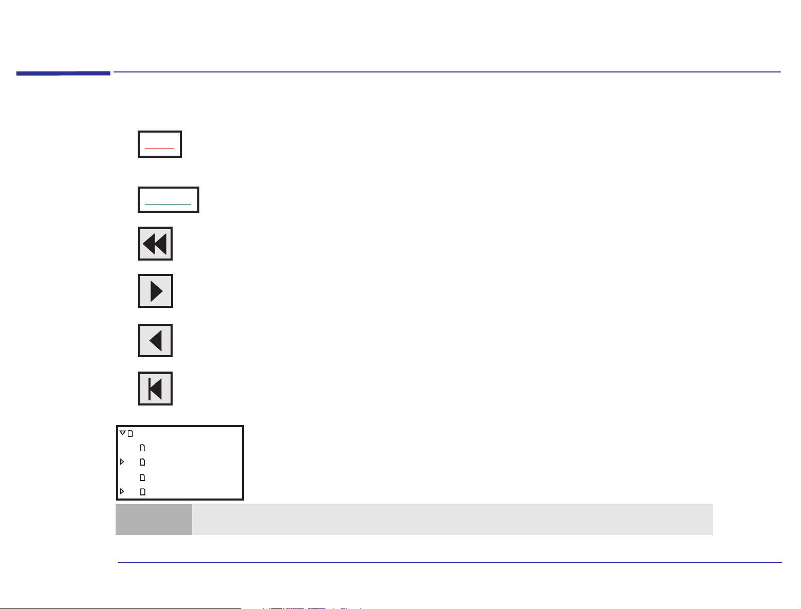
Click underlined red text to go to the topic indicated. Underlined red text is text that is “linked”
Topic
Click green text to go to the glossary, where a definition of the acronym is given.
Acronym
Click the Go Back button in the toolbar to go back to your previous place in the guide.
Click the Next Page button in the toolbar to go to the next page in the guide.
Click the Previous Page button in the toolbar to go to the previous page in the guide.
to another topic in the guide.
How to Use This Online Guide
Click the First Page button in the toolbar to go to the opening screen of the guide.
Online Reference Guide
How to Use This Guide
Notice
About This Guide
Purpose ofThis Guide
Note
You can print this book, but only in landscape format.
Click a bookmark name (to the left of the screen) to go to the topic corresponding to that
bookmark. Click the small triangle to the left of the bookmark to hide or show subordinate
bookmarks.
2
Page 3

Notice
Notice
The information contained in this document is subject to change without notice.
Hewlett-Packard makes no warranty of any kind with regard to this material, including, but not limited to, the implied
warranties of merchantability and fitness for a particular purpose. Hewlett-Packard shall not be liable for errors contained
herein or for incidental or consequential damages in connection with the furnishing, performance, or use of this material.
This document contains proprietary information that is protected by copyright. All rights are reserved. No part of this
document may be photocopied, reproduced, or translated to another language without the prior written consent of
Hewlett-Packard Company.
Microsoft®, MS-DOS® and Windows® are U.S. registered trademarks of Microsoft Corporation.
Zip™ is a trademark of Iomega Corporation.
Hewlett-Packard France
Grenoble Personal Computer Division
Technical Marketing
38053 Grenoble Cedex 9
France
1997 Hewlett-Packard Company
3
Page 4

About This Guide
About This Guide
This Online Reference Guide is broken down into three main sections:
• About Your Hardware - information about the main hardware components that make up your computer: the system
board, your sound card, your keyboard, and so on.
• About Your BIOS (Basic Input/Output system) - information about the set of programs that control the input and output
of data to peripherals.
• Upgrading and Adding Accessories - information about how to install new hardware components such as main memory
or expansion cards.
Purpose of This Guide
The purpose of this guide is to provide you with technical information about your computer. This is information that you
won’t need to reference every day, but which you will find useful if you ever want to upgrade or customize your
computer.
4
Page 5

Contents
1 About Your Hardware
How to Use This Online Guide . . . . . . . . . . . . . . . . . . . . . . . . . . . . . . . . . . . . . . . . . . . . . . . . . . . . . . . . . . . . . . . 2
Notice. . . . . . . . . . . . . . . . . . . . . . . . . . . . . . . . . . . . . . . . . . . . . . . . . . . . . . . . . . . . . . . . . . . . . . . . . . . . . . . . . . . . 3
About This Guide . . . . . . . . . . . . . . . . . . . . . . . . . . . . . . . . . . . . . . . . . . . . . . . . . . . . . . . . . . . . . . . . . . . . . . . . . . 4
Purpose of This Guide . . . . . . . . . . . . . . . . . . . . . . . . . . . . . . . . . . . . . . . . . . . . . . . . . . . . . . . . . . . . . . . . . . . . . . 4
A Quick Look Inside Your Computer . . . . . . . . . . . . . . . . . . . . . . . . . . . . . . . . . . . . . . . . . . . . . . . . . . . . . . . . . 10
System Board Layout . . . . . . . . . . . . . . . . . . . . . . . . . . . . . . . . . . . . . . . . . . . . . . . . . . . . . . . . . . . . . . . . . 10
Main Components and Features of the System Board . . . . . . . . . . . . . . . . . . . . . . . . . . . . . . . . . . . . . . . . . . 11
System Board Configuration Jumpers . . . . . . . . . . . . . . . . . . . . . . . . . . . . . . . . . . . . . . . . . . . . . . . . . . . . 12
Your Sound Card. . . . . . . . . . . . . . . . . . . . . . . . . . . . . . . . . . . . . . . . . . . . . . . . . . . . . . . . . . . . . . . . . . . . . . . . . . 13
Connecting Audio Devices to the Rear Panel . . . . . . . . . . . . . . . . . . . . . . . . . . . . . . . . . . . . . . . . . . . . . . 14
Connecting Audio Devices to the Internal Connectors . . . . . . . . . . . . . . . . . . . . . . . . . . . . . . . . . . . . . . 15
Power Consumption. . . . . . . . . . . . . . . . . . . . . . . . . . . . . . . . . . . . . . . . . . . . . . . . . . . . . . . . . . . . . . . . . . . . . . . 16
Typical Power Consumption/Availability. . . . . . . . . . . . . . . . . . . . . . . . . . . . . . . . . . . . . . . . . . . . . . . . . . 16
Your HP Enhanced Keyboard . . . . . . . . . . . . . . . . . . . . . . . . . . . . . . . . . . . . . . . . . . . . . . . . . . . . . . . . . . . . . . . 17
Using the Enhanced Keys. . . . . . . . . . . . . . . . . . . . . . . . . . . . . . . . . . . . . . . . . . . . . . . . . . . . . . . . . . . . . . 18
Configuring Keyboard Shortcut Keys . . . . . . . . . . . . . . . . . . . . . . . . . . . . . . . . . . . . . . . . . . . . . . . . . . . . 19
5
Page 6

2 About Your BIOS
The BIOS in Your Computer. . . . . . . . . . . . . . . . . . . . . . . . . . . . . . . . . . . . . . . . . . . . . . . . . . . . . . . . . . . . . . . . 22
The HP Setup Program . . . . . . . . . . . . . . . . . . . . . . . . . . . . . . . . . . . . . . . . . . . . . . . . . . . . . . . . . . . . . . . . . . . . 23
Working Within the Setup Program . . . . . . . . . . . . . . . . . . . . . . . . . . . . . . . . . . . . . . . . . . . . . . . . . . . . . . 24
Boot Device Priority . . . . . . . . . . . . . . . . . . . . . . . . . . . . . . . . . . . . . . . . . . . . . . . . . . . . . . . . . . . . . . . . . . 25
Saving Your Changes and Leaving Setup . . . . . . . . . . . . . . . . . . . . . . . . . . . . . . . . . . . . . . . . . . . . . . . . . . 25
Protecting Your Computer . . . . . . . . . . . . . . . . . . . . . . . . . . . . . . . . . . . . . . . . . . . . . . . . . . . . . . . . . . . . . . . . . 26
Restricting Access to Your Computer - Setting a Password . . . . . . . . . . . . . . . . . . . . . . . . . . . . . . . . . . . 26
Power Management in the BIOS . . . . . . . . . . . . . . . . . . . . . . . . . . . . . . . . . . . . . . . . . . . . . . . . . . . . . . . . . . . . 27
Checking Your Configuration. . . . . . . . . . . . . . . . . . . . . . . . . . . . . . . . . . . . . . . . . . . . . . . . . . . . . . . . . . . . . . . 28
Warning Messages and the Power-On Self-Test. . . . . . . . . . . . . . . . . . . . . . . . . . . . . . . . . . . . . . . . . . . . . . . . 29
Beep Codes . . . . . . . . . . . . . . . . . . . . . . . . . . . . . . . . . . . . . . . . . . . . . . . . . . . . . . . . . . . . . . . . . . . . . . . . . 29
How to Recover if Things Go Wrong. . . . . . . . . . . . . . . . . . . . . . . . . . . . . . . . . . . . . . . . . . . . . . . . . . . . . . . . . 30
System Boot Failure. . . . . . . . . . . . . . . . . . . . . . . . . . . . . . . . . . . . . . . . . . . . . . . . . . . . . . . . . . . . . . . . . . . 30
Incorrect Password on Startup . . . . . . . . . . . . . . . . . . . . . . . . . . . . . . . . . . . . . . . . . . . . . . . . . . . . . . . . . . 30
Clearing the CMOS Configuration. . . . . . . . . . . . . . . . . . . . . . . . . . . . . . . . . . . . . . . . . . . . . . . . . . . . . . . . 31
3 Upgrading and Adding Accessories
Why Upgrade? . . . . . . . . . . . . . . . . . . . . . . . . . . . . . . . . . . . . . . . . . . . . . . . . . . . . . . . . . . . . . . . . . . . . . . . . . . . 34
Upgrades and Accessories You Can Install. . . . . . . . . . . . . . . . . . . . . . . . . . . . . . . . . . . . . . . . . . . . . . . . . 35
6
Page 7

Upgrading the BIOS. . . . . . . . . . . . . . . . . . . . . . . . . . . . . . . . . . . . . . . . . . . . . . . . . . . . . . . . . . . . . . . . . . . . . . . 36
Upgrading Hardware . . . . . . . . . . . . . . . . . . . . . . . . . . . . . . . . . . . . . . . . . . . . . . . . . . . . . . . . . . . . . . . . . . . . . . 37
Removing and Replacing the Cover . . . . . . . . . . . . . . . . . . . . . . . . . . . . . . . . . . . . . . . . . . . . . . . . . . . . . . 37
Upgrading Main Memory . . . . . . . . . . . . . . . . . . . . . . . . . . . . . . . . . . . . . . . . . . . . . . . . . . . . . . . . . . . . . . . 39
Upgrading Video Memory . . . . . . . . . . . . . . . . . . . . . . . . . . . . . . . . . . . . . . . . . . . . . . . . . . . . . . . . . . . . . . 42
Upgrading a Processor. . . . . . . . . . . . . . . . . . . . . . . . . . . . . . . . . . . . . . . . . . . . . . . . . . . . . . . . . . . . . . . . . 44
Adding Accessories . . . . . . . . . . . . . . . . . . . . . . . . . . . . . . . . . . . . . . . . . . . . . . . . . . . . . . . . . . . . . . . . . . . . . . . 49
Adding Expansion Cards . . . . . . . . . . . . . . . . . . . . . . . . . . . . . . . . . . . . . . . . . . . . . . . . . . . . . . . . . . . . . . . 49
Installing an Expansion Card . . . . . . . . . . . . . . . . . . . . . . . . . . . . . . . . . . . . . . . . . . . . . . . . . . . . . . . . . . . 50
Installing Storage Devices . . . . . . . . . . . . . . . . . . . . . . . . . . . . . . . . . . . . . . . . . . . . . . . . . . . . . . . . . . . . . . 54
Changing the Battery. . . . . . . . . . . . . . . . . . . . . . . . . . . . . . . . . . . . . . . . . . . . . . . . . . . . . . . . . . . . . . . . . . . . . . 62
Appendix AT Commands
Basic AT Commands . . . . . . . . . . . . . . . . . . . . . . . . . . . . . . . . . . . . . . . . . . . . . . . . . . . . . . . . . . . . . . . . . . . . . . 64
Modem Response Messages . . . . . . . . . . . . . . . . . . . . . . . . . . . . . . . . . . . . . . . . . . . . . . . . . . . . . . . . . . . . . . . . 69
Glossary . . . . . . . . . . . . . . . . . . . . . . . . . . . . . . . . . . . . . . . . . . . . . . . . . . . . . . . . . . . . . . . . . . . . . . . . .73
Index. . . . . . . . . . . . . . . . . . . . . . . . . . . . . . . . . . . . . . . . . . . . . . . . . . . . . . . . . . . . . . . . . . . . . . . . . . . . 77
7
Page 8

8
Page 9

1
About Your Hardware
Page 10
1 About Your Hardware
A Quick Look Inside Your Computer
A Quick Look Inside Your Computer
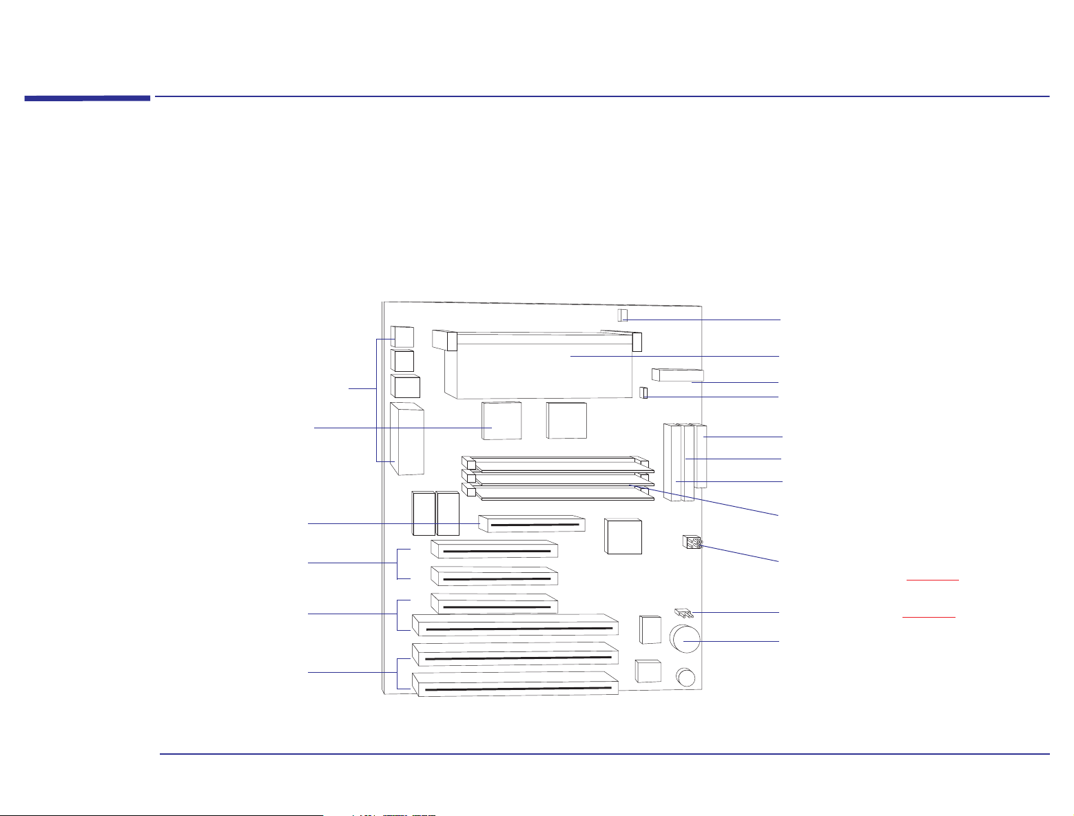
System Board Layout
The following system board block diagram will help you identify where the different components and connections are
located on the board.
Fan Chassis Connector
Processor and Socket
Rear Panel Connectors
Video Controller
AGP Slot
2 PCI Expansion
Card Slots
COMBO Slot
(PCI or ISA)
2 ISA Expansion
Card Slots
Power Supply Connector
Power Supply Fan
Floppy Disk Drive Connector
Primary IDE Connector
Secondary IDE Connector
Main Memory Module
and Sockets
Processor Frequency Selection
Jumper Strip (refer to page 47 )
Clear CMOS (refer to page 31 )
Battery
10
Page 11

1 About Your Hardware
Main Components and Features of the System Board
Main Components and Features of the System Board
The main components and features of your HP Brio PC are:
• Enhanced IDE controller with two channels on the computer bus:
❒ A primary IDE channel used, for example, for one or two IDE hard disk drives.
❒ A secondary IDE channel used, for example, for IDE CD-ROM drives, IDE hard disk drives, or IDE Zip drives.
• Floppy Disk Drive controller supporting two devices.
• Rear panel connectors:
❒ 1 mouse socket
❒ 1 keyboard socket
❒ 1 display connector
❒ 2 Universal Serial Bus (USB) connectors
❒ 1 parallel port
❒ 1 serial port
• The main memory controller supports three DIMM slots. Each slot can host a 168-pin unbuffered DIMM module, for a
total of up to 192 MB of dynamic random access memory. These slots can be filled in any order.
• Depending on the model you have purchased, your computer is supplied with one of the following:
❒ An on-board video controller with 2 MB of video memory on the system board.
❒ An AGP video card installed in the AGP expansion slot.
11
Page 12

• Six expansion card slots for the installation of:
❒ Two 32-bit PCI cards, three 16-bit ISA cards and one AGP card,
or
❒ Three 32-bit PCI cards, two 16-bit ISA cards and one AGP card.
1 About Your Hardware
Main Components and Features of the System Board
Clear CMOS
Jumper (J22)
Microprocessor
Configuration
Jumper (J23)
Note
PCI expansion card slots are generally white plastic grooves.
ISA expansion card slots are generally black plastic grooves lined with silver.
System Board Configuration Jumpers
The CMOS memory stores information, such as your computer’s configuration, which is preserved when you turn off your
computer. A jumper placed on pins 1-2 prevents changes to the CMOS configuration. This is the default setting. Refer to
“Clearing the CMOS Configuration” on page 31
This jumper allows the system board to be set so that it matches the speed of the installed processor. You only need to
change the microprocessor configuration jumper, if you install a new processor that has a different processor speed to the
one that is currently installed. Refer to “Upgrading a Processor” on page 44
processor upgrade, and changing the jumper settings.
for information about clearing the CMOS and using this jumper.
for more information about installing a
12
Page 13
1 About Your Hardware
Your Sound Card
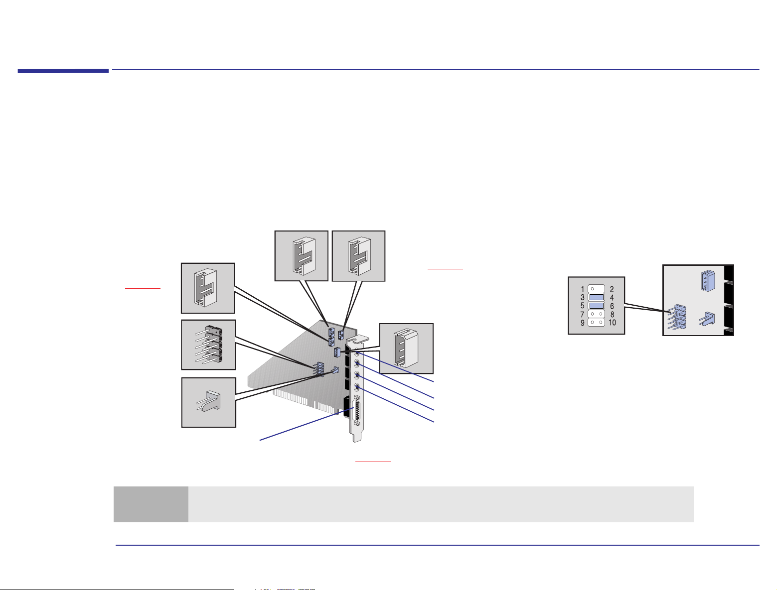
Depending on the computer you have purchased, a sound card may be already installed. The sound card has several
connectors that allow you to connect the card to other devices. This figure shows where the connectors are located on
the sound card.
Telephone Answering
Device Connector
(refer to note below)
CD Audio
Connector
AUX In Connector
(refer to page 15 )
(refer to page 15 )
Your Sound Card
Multimedia Control
Panel Connector
(refer to note below)
Internal Speaker
Connector
(refer to note below)
Note
Multimedia Control Panel
Microphone Connector
(refer to note below)
Line In
Mic
Line Out
SPK
MIDI / Game
Refer to page 14 for details about the sound card’s rear panel
The internal connectors Internal Speaker Connector, Multimedia Control Panel Connector, Telephone Answering
Device Connector and Multimedia Control Panel Microphone Connector are not used on this computer.
Jumpers are required between pins 3 and
4 and between pins 5 and 6 of the
Multimedia Control Panel Connector.
Without these jumpers, the sound card
will not output sound through the rear
panel. (These jumper connections are set
by default).
13
Page 14

1 About Your Hardware
Your Sound Card
Connecting Audio Devices to the Rear Panel
You can connect external speakers, a microphone, or other audio devices to the rear panel. Do not connect headphones
to the jack on the CD-ROM drive, as this will only let you hear output from music CDs. Through the rear panel jack on
your computer you will hear sounds from training presentations, MIDI music files, any other audio software, and music
CDs too.
Warning
Details of what each jack on the sound card is for are given below.
LINE IN Connect devices such as a cassette, DAT, or Minidisc player for playback and recording.
MIC Connect a microphone for voice input.
LINE OUT Bypass the sound card’s internal amplifier to connect powered speakers, an external amplifier for audio
SPK Connect speakers for audio output from the card’s built-in power amplifier. Adjust the volume from within
Before connecting any headphones or speakers, always turn the volume down to avoid discomfort from unexpected
noise or static. Listening to loud sounds for prolonged periods of time may permanently damage your hearing. Before
putting on any headphones, place them around your neck and turn the volume down. Then, put on the headphones
and slowly increase the volume by using the Audio Mixer Applet or the enhanced keyboard until you find a
comfortable listening level, where the sound is clear, without being too loud. When you can hear comfortably and
clearly, without distortion, leave the volume control in that position.
output, a recording device (tape deck), or stereo headphones.
You can use this jack for headphones with limited power output. You can also use it with amplified
speakers which have a dedicated headphone jack for this purpose.
the software or from the multimedia control panel if this feature is on your computer.
Warning
MIDI/GAME Connect a joystick (for game software) or MIDI instrument. The MIDI port is disabled by default. You will
The SPK jack is for a highly amplified output and is therefore not suitable for connecting headphones.
have to enable this port if you wish to use it with a MIDI.
14
Page 15

1 About Your Hardware
Your Sound Card
Connecting Audio Devices to the Internal Connectors
There are also several internal connectors located on the sound card itself. These are shown on page 13 , and those that
are used are described below.
AUX In Connector This Auxiliary Connector allows you to connect an additional internal audio source such as a TV tuner, or another similar
card. It can also be used to accept decompressed audio data from an MPEG video card. The AUX In connector has the
following pin assignments:
Pin Signal I/O
1 Analog Ground -
2 AUX right channel IN
3 Analog Ground 4 AUX left channel IN
CD Audio Connector The CD Audio Connector, labeled “CDAUDIO”, allows you to connect the sound card to the CD-ROM drive via the audio
cable, so that you can listen to audio from the CD-ROM drive. The CD Audio Connector has the following pin
assignments:
Pin Signal I/O
1 Analog Ground 2 CD right channel IN
3 Analog Ground -
4 CD left channel IN
15
Page 16
Power Consumption
1 About Your Hardware
Power Consumption
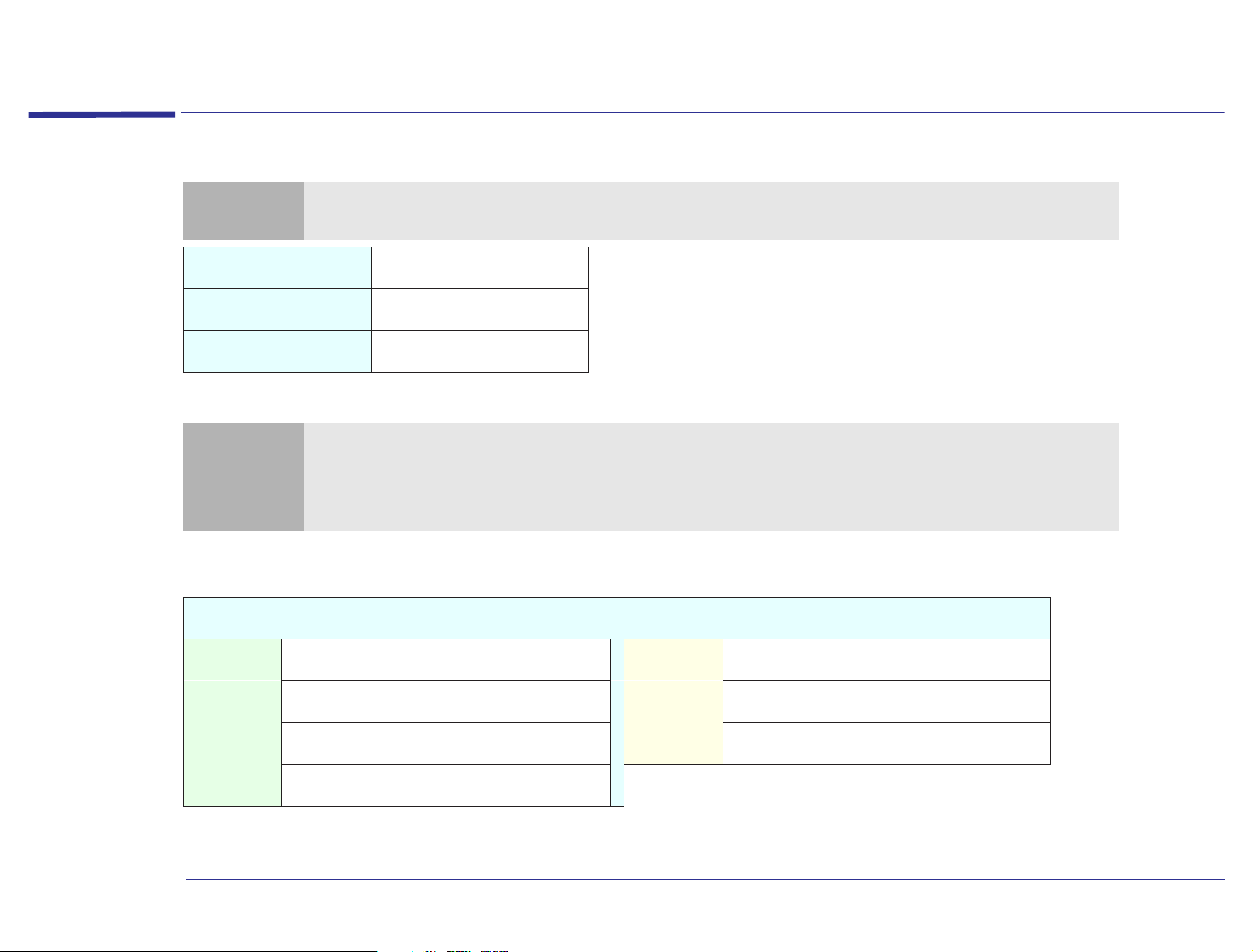
Note
Full Power Mode
Suspend Mode
Off
1. The power supply in your HP PC continues to supply power to the CMOS memory, even when turned off.
Note
The figures given below are valid for computers with a standard configuration—no expansion cards and no CD-ROM
drive. For certain configurations, the power consumption values will be higher.
<44 W
<30 W
1
<3 W
When the computer is turned off with the power button on the front panel, the power consumption falls below 3
watts, but it is not zero. The special on/off method used by this computer considerably extends the lifetime of the
power supply. To reach zero power consumption in “off” mode, either unplug the computer from the power outlet or
use a power block with a switch.
Typical Power Consumption/Availability
PCI Expansion Card Slots
4.5A maximum per slot
+ 5 V
ISA Expansion Card Slots
4.5A limit per slot (limited by system board)
+ 5 V
+ 12 V
- 5 V
- 12 V
There is a maximum per-slot limit of 25 W between all supply rails.
1.5A limit per slot (limited by system board)
0.1A total power limit (limited by power supply)
0.3A total power limit (limited by power supply)
+ 12 V
- 12 V
0.5A maximum per slot
0.1A maximum per slot
16
Page 17
1 About Your Hardware
Your HP Enhanced Keyboard
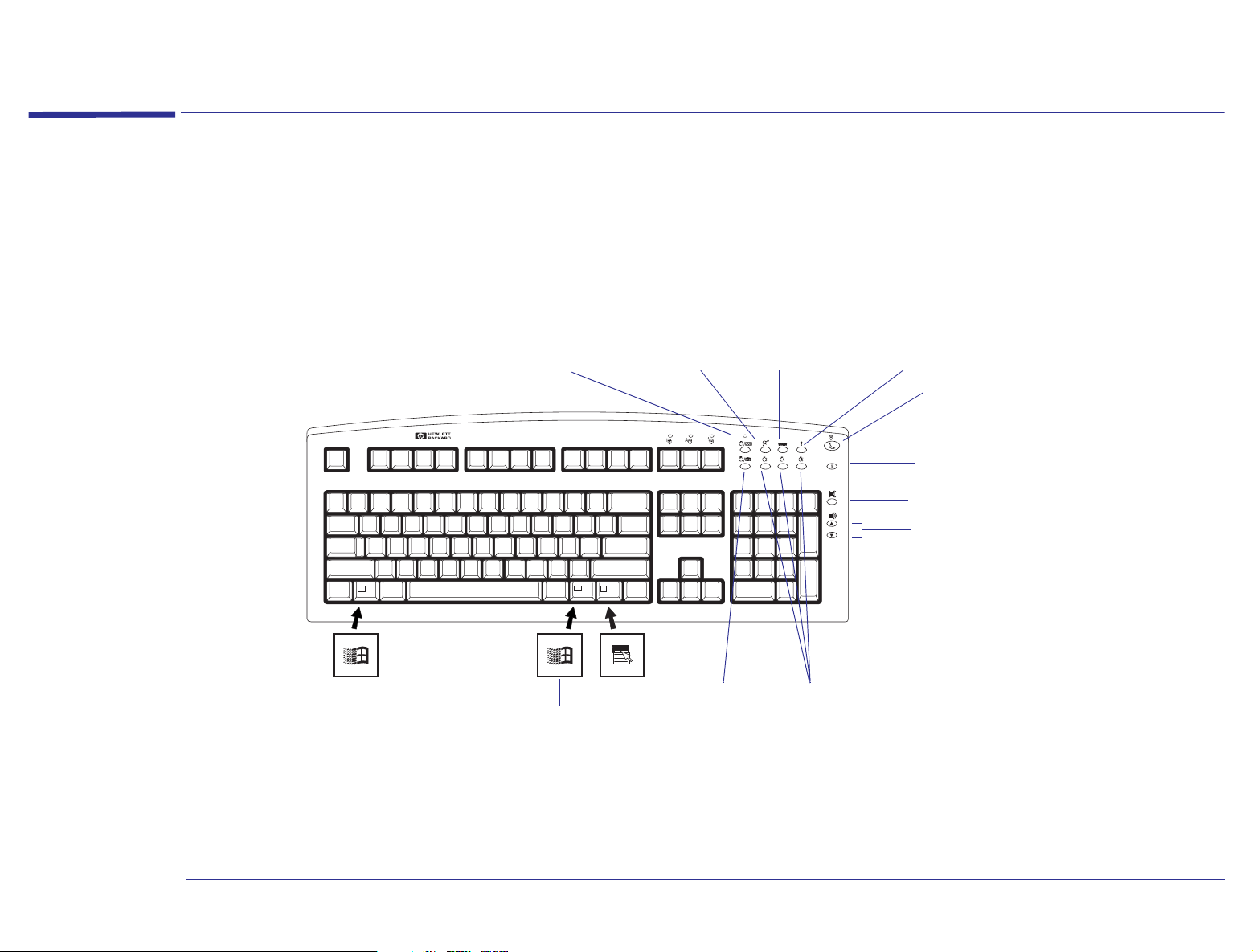
Your HP Enhanced Keyboard
Depending on the computer you have purchased, you may have the HP Enhanced Keyboard. As well as offering standard
keys, the Enhanced Keyboard allows you direct access to various software applications. You can also create your own
shortcuts to your most frequent tasks by configuring certain keys. For example, you can access your word processor
application at a touch of the single key.
Messages key, with
mail LED
Display the Windows Start menu by
pressing either of the two Windows
keys.
HP Brio Center WEB browser Menu key
Suspend key
Information
Mute
Volume control
Phone key Shortcut keys
Access the rightmouse-button
functions.
17
Page 18

Using the Enhanced Keys
The keys are located on the top right-hand side of the keyboard and can be used as follows:
1 About Your Hardware
Your HP Enhanced Keyboard
Key Function
Messages and LED
HP Brio Center
Web Browser
Menu
Suspend
Information
Mute and Volume Control
Configurable
Key
Monitors the arrival of fax messages or electronic mail. The LED blinks when a new fax or E-mail arrives. The LED
is turned off when you open the message. Press this key to launch your e-mail application.
Accesses the HP Brio Center. No
Launches the default Internet browser configured in your system. No
Displays a window displaying the current configuration of the keys and the actions mapped to them. Pressing the
Menu key again will close this window without further action needed. Pressing any other extended key will close
the window and launch the associated command.
This key can be used to either turn on the power saving capabilities if configured in the Control Panel, or start the
screen saver. It is recommended that you configure your screen saver with a password to lock the computer when
the screen saver is activated. A screen saver will not be cleared until the correct password has been typed.
Accesses the information section of the HP Brio Center. No
Press the Mute key to mute the audio. The volume keys are used to adjust the volume level. If no sound card is
installed in your computer, a warning will be displayed on the screen if one of these three keys is pressed.
Yes. Refer to
page 19
No
No
No
Shortcuts
(S3, S4, S5)
Phone
You can assign these keys to start applications, open files, or open URLs on the Internet. For example, you can
access your word processor application at the touch of a single key.
This key can be used to access telephone directory sites world-wide. To do this, however, you must have an
Internet connection. You can also configure this key in the same way as the shortcut keys.
Yes. Refer to
page 19
Yes. Refer to
page 19
18
Page 19
1 About Your Hardware
Your HP Enhanced Keyboard
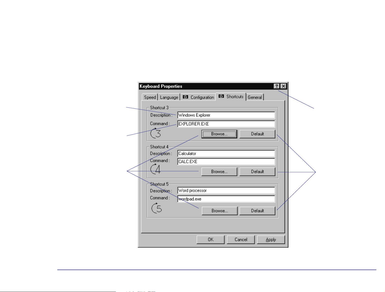
Configuring Keyboard Shortcut Keys
You have three standard configurable shortcut keys (S3, S4, S5). You can configure shortcut keys from the Control Panel.
Double-click the Keyboard icon, then select the Shortcuts tab from the Keyboard Properties screen. To define a Shortcut
key, you need to:
Provide a Description of the
application you are assigning to
the Shortcut key.
Provide a Command, which is
the executable that starts the
application.
Click here to activate the
Question Mark pointer. Then
click any element to obtain
information.
Use the Browse button to
locate the file you want to use
in the Command field.
Click here to restore the
default settings for the
shortcut key.
19
Page 20
1 About Your Hardware
Your HP Enhanced Keyboard
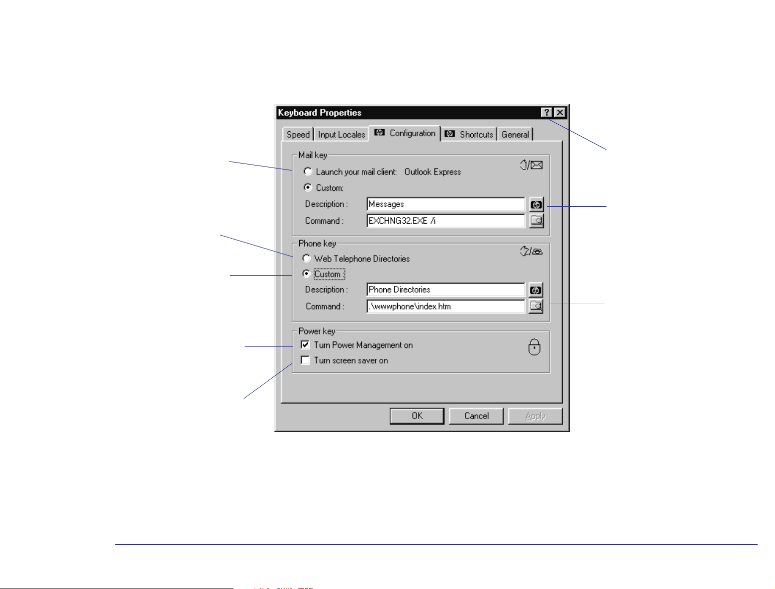
You can also reconfigure the mail, phone, and power keys on your keyboard. Double-click the Keyboard icon, then select
the Configuration tab from the Keyboard Properties screen.
Launch your default mail
client that has been
configured in your Internet
settings.
Link to several telephone
directories world-wide.
Create a link to your
frequently used telephone
directory on the Web.
Reduce the power used by the
computer by putting it in
suspend mode. This option is
activated by pressing the
Suspend key
Launch the screen saver when the
Suspend key is activated
1
.
Click here to activate the
Question Mark pointer. Then
click any element to obtain
information.
Click this button to restore the
default settings for the shortcut
key.
Click this button to browse
through the folders to locate
the file you want to use in the
Command field.
1. The Turn Power Management on and
Turn screen saver on options can both be enabled at the same time
20
Page 21

2
About Your BIOS
Page 22

The BIOS in Your Computer
What Is the BIOS? The BIOS has two main roles:
• It tests and configures the computer’s hardware components during the POST, and lets you perform further
configuration by using the Setup program.
• It provides the link between the software running on your computer, which has been written to be independent of any
particular computer, and your computer’s hardware (the hard disk, the keyboard, the display, and so on).
The BIOS is part of the System ROM and is stored in a chip on the system board. A computer’s BIOS is specific to that
computer.
2 About Your BIOS
The BIOS in Your Computer
What Can I Do with
the BIOS?
You can configure certain aspects of your computer by using the Setup program which is part of the BIOS. Refer to “The
HP Setup Program” on page 23 for more information about the Setup program.
22
Page 23

2 About Your BIOS
The HP Setup Program
The HP Setup Program
The built-in Setup program is accessed by pressing the key during the POST. Online help for an item on the Setup
screen can be obtained by highlighting the item (refer to page 24
is then displayed on the right of the screen. It is updated as you move the cursor to each field.
If you have any doubts about using the Setup program, contact your reseller for help.
The band along the top of the screen offers the following menus:
• Main: for basic system configuration.
• Advanced: for setting the Advanced Features.
• Security: for setting a password to restrict access to your computer. For information on how to set a password, refer
to “Restricting Access to Your Computer - Setting a Password” on page 26
for instructions on how to use the key functions). Help
.
• Power: for selecting power-management modes to reduce the amount of energy used after specified periods of
inactivity. Refer to “Power Management in the BIOS” on page 27
.
• Boot: for choosing your boot device order and priority. Refer to “Boot Device Priority” on page 25.
• Exit: for leaving the Setup program. Refer to “Saving Your Changes and Leaving Setup” on page 25.
The Setup program changes system behavior by modifying the power-on initialization parameters. Setting incorrect
values may cause system boot failure. Should this occur, press the key while you are in the Setup program to load
the Setup program’s default values. This should enable the computer to boot properly.
HP strongly recommends that you make a note of any changes you make while in the Setup program.
23
Page 24

2 About Your BIOS
The HP Setup Program
Working Within the Setup Program
The following key functions are available when using the HP Setup program.
• The or arrows can be used to select fields in the current menu.
• The key moves the cursor to the top item, and the key moves the cursor to the bottom item of the
current menu.
• The key displays a sub-menu for menu items marked with a solid right arrow .
• The key or + keys allow you to exit from a sub-menu.
• The and arrows select menus from the menu bar.
• The key loads factory-installed default values.
• The key saves and exits from the Setup program.
• The key or + keys display the general help screen.
• The key exits from the general help screen.
Pressing the or arrows while you are on a main menu screen will take you to the next menu option. If, however,
you are on a sub-menu screen and you press these arrows, you will stay on that screen.
Use the and arrows to scroll through the items on the general help screen.
24
Page 25

2 About Your BIOS
The HP Setup Program
Boot Device Priority
You can select the order of the devices from which the BIOS attempts to boot the operating system. During the POST, if
the BIOS is unsuccessful at booting from one device, it will try the next one on the Boot Device Priority list until an
operating system is found. The default boot device is the floppy disk. To speed up booting, you may wish to set the hard
disk as the default boot device. If you ever need to boot from a floppy though, remember to reset the floppy as the
default boot device.
The Boot Device Priority can be changed through the Boot menu. Use the or arrows to move along the top of
the main menu bar to its location. The item is then highlighted and displays the available boot options.
Main PowerAdvanced Security ExitBoot
To select the boot device, use the and arrows, then press the key to move the device up the list, or the
key to move it down the list.
Changing the Boot Device Priority for the current boot:
You can also change the boot order just for the current boot. To do this, press while the logo and the message Pr ess
<F2> to enter SETUP are displayed during system startup. This initially displays the POST before displaying the
Boot Menu. On the Boot Menu use the and arrows to select the device from which you want to boot, and then
press . The computer then attempts to boot from the selected drive.
Saving Your Changes and Leaving Setup
When you have made all your changes, you must save them and exit Setup.
1 Press the key to enter the Exit menu.
2 Select Exit Saving Changes to save your changes and exit Setup.
The computer will automatically restart. If you set a Password, the computer will display the power-on prompt. Enter the
Password to use the computer.
25
Page 26

Protecting Your Computer
Restricting Access to Your Computer - Setting a Password
2 About Your BIOS
Protecting Your Computer
Note
It is recommended that you set a password that you can easily remember.
Setting a Password Set a password to protect your computer’s configuration by preventing access to the Setup menus. Full access to the
Setup menus will only be possible by using your password. To set a Password:
1 Start the Setup Program. Refer to “The HP Setup Program” on page 23.
2 Select the Security menu group. Then select the “Set Password” item.
3 You will be asked to enter your password twice. Be sure to save your changes before you exit the Setup program.
Password on Boot Enabling a password entry on boot can provide a power-on password prompt to prevent your computer being started or
used in your absence. The password is entered when the POST has completed, before the computer finishes its normal
startup procedure. Password on boot can only be enabled if the Password has already been set. It should be noted that
this password option is not linked with your Windows operating system.
After three unsuccessful attempts, your computer will be disabled. If this is the case, turn your computer off and
Note
then on again, then enter the correct password. If you have forgotten your password, you need to clear the CMOS
configuration. Refer to page 31
for an explanation on how to clear the CMOS.
To enable a Password on Boot:
1 Start the Setup Program.
2 Select the Security menu group. Then enable the “Password on Boot” item.
3 Be sure to save your changes before you exit the Setup program.
26
Page 27

2 About Your BIOS
Power Management in the BIOS
Power Management in the BIOS
If your computer stays idle for a certain amount of time, your system BIOS switches the system from Full Power Mode to
Suspend Mode in order to reduce power consumption.
In Suspend Mode, graphics, the processor and hard disks are stopped. Any user event, such as from the mouse or
keyboard, will cause the system to resume to Full Power Mode within a few seconds.
Other events may also wake up the system: a daily alarm clock (for a scheduled backup), a ring on an external modem,
an IRQ signal sent by an expansion card (modem, network card, etc.).
To customize the power management settings though the HP Setup program, use the or keys to move along the
top of the main menu bar to the Power Menu. The item is then highlighted and displays the available power management
options.
Main Advanced Security ExitBootPower
You will be able to set the delay before the system can automatically enter Suspend Mode, and also specify the events
which will make the computer wake up.
In most cases, default settings should be appropriate. However, you may need to configure the IRQs which will be
monitored in accordance with your system components (additional network card or modem ...). For this, select the field
>IRQ Activity Monitoring.
Note
Windows can provide you with a list of IRQs used by all system components: right-click the My computer icon, select
Properties, select the Device Manager tab, then click Properties. The list of IRQs used will be displayed.
27
Page 28

2 About Your BIOS
Checking Your Configuration
Checking Your Configuration
To view your computer’s current configuration, press the key just after you computer is turned on and while the
computer’s logo is being displayed during the POST.
The text-based POST screen will replace the computer’s logo, displaying the system components and devices. Press the
Pause/Break key to “freeze” the screen. When you have finished reading the POST screen, press any key to continue. At
the end of the POST screen, the Boot Menu will be displayed.
You can either, select to exit the menu by pressing the key, or enter the Boot Menu to modify the device for the
current boot. How to modify the current boot device priority is described in “Changing the Boot Device Priority for the
current boot:” on page 25.
28
Page 29

2 About Your BIOS
Warning Messages and the Power-On Self-Test
Warning Messages and the Power-On Self-Test
The POST is executed each time the system is turned on or a reset is performed. The POST process checks that system
components are operating correctly and initializes certain system parameters.
Beep Codes
If a terminal error occurs during POST, the system issues a beep code before attempting to display the error. Beep codes
are useful for identifying the error when the system is unable to display the error messages.
The following table is a list of beep codes issued for terminal errors.
Beep Pattern Numeric Code Description
B4h This does not indicate an error
There is one short beep before system startup
16h BIOS ROM checksum failure
20h DRAM refresh test failure
22h 8742 Keyboard controller test failure
2Ch RAM failure on address line
2Eh RAM failure on data bits in low byte of memory bus
30h RAM failure on data bits in high byte of memory bus
46h ROM copyright notice check failure
58h Unexpected interrupts test failure
98h Video configuration failure or no card installed
Option ROMs checksum failure
29
Page 30

2 About Your BIOS
How to Recover if Things Go Wrong
How to Recover if Things Go Wrong
System Boot Failure
If you have made some modifications in the Setup program and there is a system boot failure, you should do the
following:
1 Restart the computer, then press when Press <F2> to enter SETUP is displayed at the bottom of the screen.
Change the setting that you have modified to its original configuration, save it and exit the Setup program, then
continue with the system startup.
2 If the system still fails to start up, restart the computer, enter the Setup program, then press the key. This will load
the Setup default values to recover. However, by doing this, you will lose all customized settings in the Setup program.
These settings will have to be reconfigured.
Note
If you are having problems with POST error messages, you probably need to clear the current configuration memory
values and reset the built-in default values. Refer to “Clearing the CMOS Configuration”
this.
HP strongly recommends that you take note of any change to the system setup and store it in a safe place. If you
have any doubts about using the HP Setup program, contact you HP-authorized support agent or reseller for help.
below for details on how to do
Incorrect Password on Startup
After three unsuccessful attempts to enter the correct password on Password on Boot, your computer becomes
disabled. If this happens, turn your computer off and then on again, then enter the correct password. If you have
forgotten your password, you need to clear the CMOS configuration. Refer to “Clearing the CMOS Configuration”
for details on how to do this.
below
30
Page 31

2 About Your BIOS
How to Recover if Things Go Wrong
Clearing the CMOS Configuration
The CMOS memory stores information, such as your computer’s configuration, which is preserved when you turn off your
computer. The only time you need to clear the CMOS is if the configuration stored in memory is corrupted or you have
forgotten the system password. A jumper placed on pins 1-2 prevents changes to the CMOS configuration.
The following table shows the possible pin settings:
Jumper Function Pins Description
Default setting 1 - 2
Clear CMOS
To clear the configuration:
1 Turn off the computer. Unplug the computer from the electrical socket. Disconnect any peripherals from the computer.
Note
2 Remove the computer’s cover (refer to “Removing and Replacing the Cover” on page 37
3 Place the jumper on pins 2-3 (refer to page 10
CMOS).
4 Wait for a couple of seconds, then place the jumper on pins 1-2 to re-enable the configuration.
5 Replace the cover. Reconnect the power cord and any peripherals to the computer.
6 Turn on the computer.
To set a new system password, you will need to run the Setup program.
The CMOS will be cleared only if the computer is unplugged from the electrical socket.
2 - 3 Place the jumper on these pins to clear the CMOS. You only need to leave it there for a
The jumper on these pins prevents any change to the CMOS configuration. Refer to page
10 for the jumper position on the system board.
few seconds, otherwise you run the risk of discharging the battery.
for any assistance).
for the jumper strip (J22) location on the system board to clear the
31
Page 32

2 About Your BIOS
How to Recover if Things Go Wrong
32
Page 33

3
Upgrading and Adding Accessories
Page 34

3 Upgrading and Adding Accessories
Why Upgrade?
Why Upgrade?
Your computer uses some of the latest hardware technology to achieve outstanding performance. If required,
performance can be even further enhanced thanks to this computer’s upgradeable design.
Main Memory Main memory is the workspace of the computer in which the processor stores all work in progress. You can increase the
size of the computer’s workspace by adding more main memory.
To find out more about upgrading the main memory, refer to “Upgrading Main Memory” on page 39.
Video Memory Video memory stores everything that you see on your computer screen. In order to provide a solid image on the screen,
the screen image has to be continually refreshed. The computer’s graphics system uses the image stored in video memory
to refresh the screen. Increasing the amount of video memory enables higher screen resolutions, higher refresh rates and
many more colors for existing resolutions, enhancing and accelerating graphics-intensive applications.
To find out more about upgrading the video memory, refer to “
Upgrading Video Memory” on page 42.
Expansion Cards An expansion card, or accessory board, is a component that usually adds some specialized function to a computer. For
example, installing a network card can, in conjunction with the necessary software and cables, connect a computer to a
network.
To find out more about installing expansion cards, refer to “Adding Accessories” on page 49.
Storage Devices A storage device is a device that stores software (for example, applications, programs, the operating system, data, and so
on). Hard disk drives, CD-ROM drives, tape drives, Zip drives, and floppy disk drives are all examples of storage devices.
To find out more about installing storage devices, refer to “Installing Storage Devices” on page 54.
Processor The processor is the primary computational chip inside the computer. It can be thought of as the computer’s brain. It may
be upgraded to provide more power for processor-intensive applications.
To find out more about installing a processor upgrade, refer to “Upgrading a Processor” on page 44.
34
Page 35

Upgrades and Accessories You Can Install
Some of the additional accessories that you can add to your computer are shown here.
Front-Access Device Shelves
· CD-ROM Drive bay
· 5.25-inch Accessory bay
· 5.25-inch Floppy or Hard Disk Drive bay
· 3.5-inch Floppy Disk Drive (Drive A)
· Second 3.5-inch Floppy Disk, Zip or Tape Drive bay
Front Bezel
3 Upgrading and Adding Accessories
Why Upgrade?
Fan Chassis Connector
Processor Upgrade
Power Connector
Main Memory
Upgrade Modules
16 MB, 32 MB or
64 MB
IDE and Floppy Drive
Connectors
AGP Video Slot
†
Expansion Cards
For example, a sound card
† Sockets are shown filled. Empty sockets on your computer’s system
board indicate that an upgrade is possible.
Contact your reseller for HP accessory part numbers.
System Board
Extension Card Slots
Battery
BIOS Flash
35
Page 36

Upgrading the BIOS
What Is the BIOS? For a description of the BIOS, refer to “The BIOS in Your Computer” on page 22.
3 Upgrading and Adding Accessories
Upgrading the BIOS
Why Upgrade the
BIOS?
How Do I Upgrade
the BIOS?
Hewlett-Packard are continually improving the BIOS in their computers, introducing new features and making them more
efficient. You can therefore keep your own computer up-to-date by upgrading the BIOS.
To upgrade your system BIOS, download the appropriate BIOS utility from our support WEB site:
http://www.hp.com/go/smallbizsupport
36
Page 37

Upgrading Hardware
3 Upgrading and Adding Accessories
Upgrading Hardware
Warning
For your safety, never remove the computer’s cover without first removing the power cord and any connection to a
telecommunications network. Always replace the cover before reconnecting any cables to your computer.
Removing and Replacing the Cover
You need to remove the computer’s cover to install accessories or to gain access to the system configuration jumpers.
Removing the Cover 1 Turn off the computer and display, and disconnect all power supply cords and any telecommunications cables.
2 If necessary, unlock the cover using the key on the back panel. Remove the four screws from the back of the computer.
3 Pull the cover back 1.5 cm, then lift the cover completely off the computer’s chassis.
1.5 cm
37
Page 38

3 Upgrading and Adding Accessories
Upgrading Hardware
Replacing the Cover 1 Check that you have installed all your accessories and that internal cables are properly connected and safely routed
(for example, check that they will not interfere with the cover when it is replaced).
2 Lower the cover onto the computer. Position the cover so that there is a 1.5 cm gap between the front edge of the cover
and the front bezel.
3 While holding the cover as shown, lift the cover up approximately 1 cm until a ‘pop’ is heard, then lower the cover. Metal
tabs at the bottom of the cover should now be hooked onto the chassis of the computer.
4 Push the cover forward until it meets the front bezel. Secure the cover in place by replacing the four screws on the rear
panel. If required, lock the cover using the key provided.
1.5 cm
1 cm
5 Reconnect the power supply cords and any telecommunications cables. Turn on the display and computer.
38
Page 39

Upgrading Main Memory
3 Upgrading and Adding Accessories
Upgrading Hardware
How Much Main
Memory Does My
Computer Have?
Why Add More Main
Memory?
How Much Main
Memory Can I Add?
Will Adding Memory
Always Improve
Performance?
The amount of main memory that your computer has depends on the particular model that you have. To see how much
main memory is installed, right-click the My Computer icon on the desktop. Then click Properties in the drop-down menu.
By adding more memory you can significantly improve the computer’s performance. If your computer does not have
enough memory, it uses hard disk space as virtual memory which allows large applications to execute even though the
physical memory is not sufficient. Virtual memory, however, is approximately 200 times slower than main memory.
The amount of main memory your computer requires depends on the operating system and the applications you use. You
may need more memory if you use memory-hungry applications (for example, image processing and desktop publishing
applications) or if you run several applications at the same time.
Your computer is capable of supporting up to 192 MB of main memory (3 x 64 MB), using three memory module sockets
on the system board.
Main memory is available in modules of 16 MB, 32 MB, and 64 MB non-ECC SDRAMs.
If your computer has sufficient memory, installing extra memory will not improve performance.
39
Page 40
3 Upgrading and Adding Accessories
Upgrading Hardware
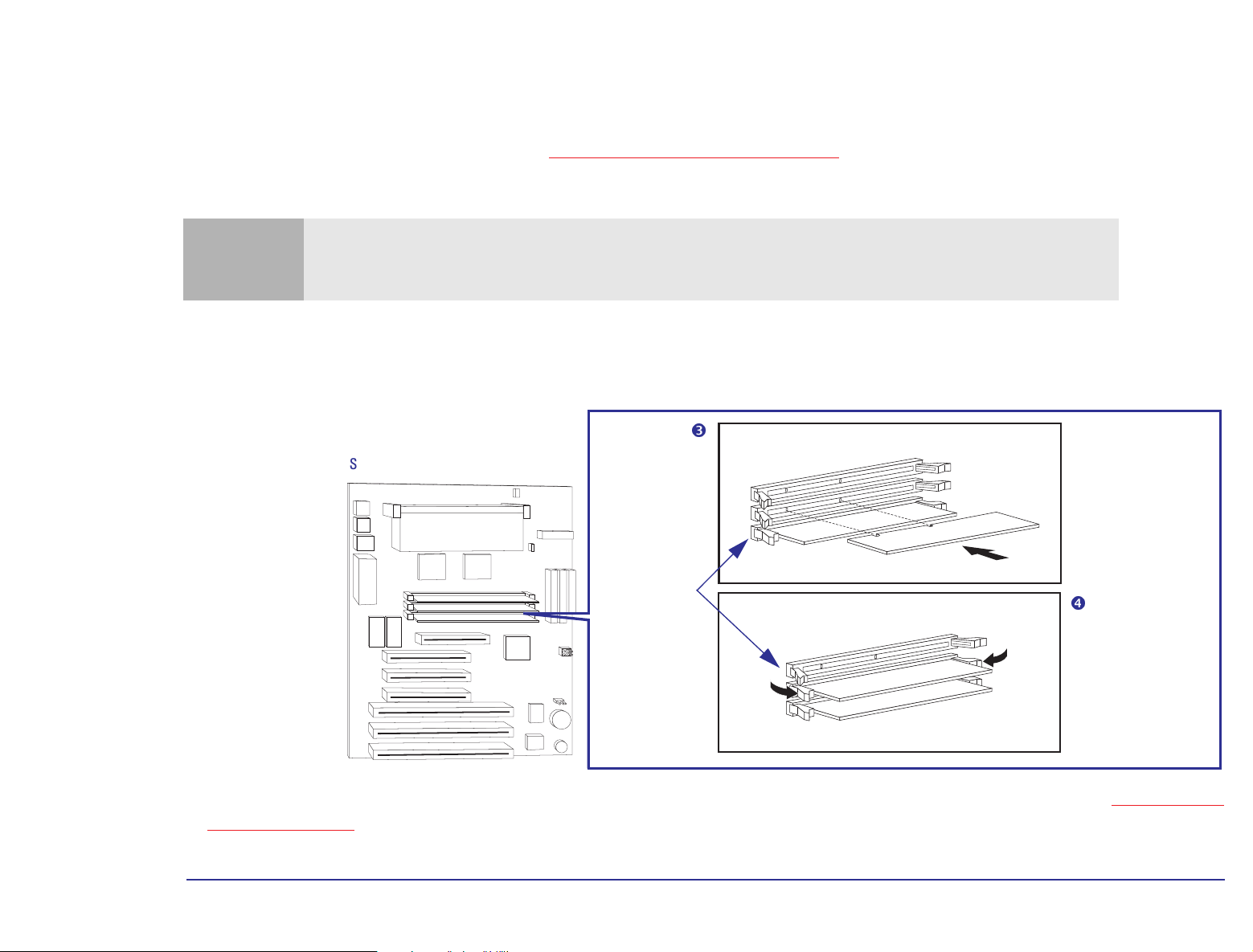
Installing Main Memory Modules
1 Remove the computer’s cover (refer to “Removing the Cover” on page 37).
2 On a table top turn the computer on to its side, with the system board closest to the surface of the table top.
Caution
3 Handle the memory module by its edges. Slide the memory module into the connector at 90
module will only fit into the socket one way round).
4 Firmly press the memory module completely into the connector until the retaining clips click into position.
Static electricity can damage electronic components. Turn off all equipment. Don’t let your clothes touch the
accessory. To equalize the static electricity, rest the accessory bag on top of the computer while you are removing
the accessory from the bag. Handle the accessory as little as possible and with care.
o
to the system board (the
System Board
Retaining Clips
5 If you need to remove a memory module, perhaps because you are replacing an existing module, refer to “Removing a
Memory Module” below.
40
Page 41

3 Upgrading and Adding Accessories
Upgrading Hardware
6 Install any other accessories before returning the computer to the upright position, replacing the cover, and
reconnecting the power supply cords and any telecommunications cables.
7 Turn on the display, and then turn on the computer.
8 In Windows, check that the new memory has been recognized. To do this, right-click the My Computer icon on the
desktop, then click Properties in the drop-down menu.
Troubleshooting ❒ If the new memory is not recognized, check that you have correctly followed the installation procedure described
above.
❒ If there are any errors reported during the computer’s startup routine, press to view the error(s) and take any
necessary action. If you have any doubts about using the HP Setup program, contact your reseller for help.
❒ If you cannot start your computer properly, remove the memory and try starting your computer again. If the computer
now starts without any problems, there may be a problem with the new memory.
❒ If you experience any other problems as a result of the upgrade, and your computer is supplied with the HP Brio Center,
refer to the support tools for further assistance.
Removing a
Memory Module
If you need to remove a main memory module, release the retaining clips at both ends of the socket. This raises the module
out of the socket. Handle the memory module by its edges, then lift it up and clear of the system board.
Release the
retaining clips
41
Page 42

Upgrading Video Memory
3 Upgrading and Adding Accessories
Upgrading Hardware
How Much Video
Memory Does My
Computer Have?
Why Increase the
Amount of Video
Memory?
How Much Video
Memory Can I Add?
The amount of video memory that your computer has depends on the particular model that you have. To find out how
much video memory is installed, select the Display icon from the Control Panel and click the Settings tab, then select the
Advanced Properties button.
You should upgrade the amount of video memory if you want to increase your display resolution or the number of
displayable colors.
For example, with 1 MB, you can have up to 65K colors with a screen resolution of 800 x 600 (default setting). If you
increase the resolution to 1024 x 768, you will only be able to have 256 colors available, which will result in a flickering
and bad ergonomic display. In this case, 2 MB of video memory is necessary to keep the optimal colors and refresh rate.
If your computer has 2 MB of video memory on the system board, it cannot be increased (unless you use a separate video
card, such as an AGP video card).
If your computer has an AGP video card supplied with 4 MB of video memory, you can upgrade it to 8 MB by installing a
video memory module.
Note
If you install an AGP video card, the video memory on the system board (if any) will no longer be available. The 2 MB
of system board video memory is not added to the total amount of available video memory.
42
Page 43

Installing Video Memory on an AGP Video Card
3 Upgrading and Adding Accessories
Upgrading Hardware
Caution
1 Remove the computer’s cover (refer to “Removing the Cover” on page 37).
2 On a table top turn the computer onto its side, with the system board closest to the surface of the table.
3 Carefully remove the card from the AGP expansion card slot. Handle the card by its edges. Do not bend the card. With
its components facing up, place the card on a clean, flat, solid, static-free surface. If you have any doubts about
removing an expansion card, refer to “Removing an Expansion Card” on page 53
4 Install the video memory upgrade module in the upgrade socket.
5 Replace the AGP video card in the computer. Carefully slide the card back into its expansion slot. Firmly press the card
into the slot. Make sure that the card slides into the slot completely and does not touch any components on other cards.
Secure the AGP video card. How to install an expansion card is described on page 50
6 Install any other accessories before returning the computer to the upright position, and replacing the cover. Reconnect
all cables and power cords.
7 Turn on the display, and then turn on the computer.
Static electricity can damage electronic components. Turn off all equipment. Don’t let your clothes touch the
accessory. To equalize the static electricity, rest the accessory bag on top of the computer while you are removing
the accessory from the bag. Handle the accessory as little as possible and with care.
.
8 In Windows, change the video resolution and the number of colors displayed. To do this, right-click on the desktop, and
then click Properties, then select the Settings tab.
Note
If you need to use a special video driver for your application, you may be asked to insert the CD-ROM or floppy disk
containing the driver.
43
Page 44

3 Upgrading and Adding Accessories
Upgrading Hardware
Troubleshooting ❒ If the new memory is not recognized, check that you have correctly followed the installation procedures described
above.
❒ If there are any errors reported during the computer’s startup routine, press to view the error(s) and take any
necessary action. If you have any doubts about using the HP Setup program, contact your reseller for help.
❒ If you cannot start your computer properly, remove the memory and try starting your computer again. If the computer
now starts without any problems, there may be a problem with the new memory.
❒ If you experience any other problems as a result of the upgrade, and your computer is supplied with the HP Brio Center,
refer to the support tools for further assistance.
Upgrading a Processor
Why Upgrade the
Processor?
What Is the Fastest
Processor I Can
Install?
The speed at which the processor can perform tasks is determined by the processor’s internal speed; the faster the
internal speed, the faster tasks can be performed. Replacing the processor by one with a faster internal speed will
improve the performance of your computer.
New, faster processors are being developed all the time. Check with your reseller to find out what is the fastest processor
that you can install in your computer. Information about processor upgrades is also available at:
http://www.hp.com/go/smallbizsupport
44
Page 45

Installing a Processor Upgrade
3 Upgrading and Adding Accessories
Upgrading Hardware
Removing the Old
Processor
1 Remove the computer’s cover (refer to “Removing the Cover” on page 37).
2 On a table top turn the computer on its side, with the system board closest to the surface of the table top.
3 Remove the airflow guide covering the processor: open the retaining clips on top of the airflow guide, slide it back so
that it clears the fan, then lift it out of the computer.
System Board
Processor and
Processor Socket
Retaining clips
45
Page 46

3 Upgrading and Adding Accessories
Upgrading Hardware
4 Squeeze the tabs on either side of the processor and gently pull the processor away from the system board.
Installing the New
Processor
1 Verify that the tabs on either side of the processor are open.
2 Slide the new processor into the processor socket and push gently until it snaps into place (the processor can only go
in one way).
46
Page 47

3 Upgrading and Adding Accessories
Upgrading Hardware
Setting the System
Board for the
Processor Type
Set the system board configuration jumpers (or jumper block).
The following diagram shows the location on the system board of the jumpers used to configure the computer for the
new processor. If you are in any doubt as to whether you should change jumper settings or not, contact your reseller.
System Board
Fan Chassis Connector
Sample configuration
jumper setting for a
233 MHz processor (if no
jumper block is used)
1
9
J23
2
10
CPU Clock Ratio (J23):
CPU SPEED
CPUCLK Ratio Jumper Position
233 MHz 2 / 7 1-2 and 9-10
266 MHz 1 / 4 5-6, 7-8 and 9-10
300 MHz 2 / 9 5-6 and 9-10
333 MHz 1 / 5 7-8 and 9-10
Completing the
Installation
Note
If your computer is supplied with a jumper block, you will need to change this with individual jumpers when you
upgrade the processor.
1 Replace the airflow guide covering the processor. Verify that the Fan cable is still connected to the Fan Chassis
Connector on the system board.
2 Install any other accessories before returning the computer to the upright position, replacing the cover, and
reconnecting the power cords and any telecommunications cables.
3 Turn on the display and computer. The computer should recognize the new processor.
47
Page 48

3 Upgrading and Adding Accessories
Upgrading Hardware
Troubleshooting ❒ If the new processor is not recognized, the startup routine will stop shortly after you turn on the computer. If this
happens, turn off the computer and check that you have correctly installed the processor.
❒ If the new processor is still not recognized, remove it and put the old processor back into the computer (remember to
reset any system board jumpers if necessary), and then restart the computer. If the computer now starts without any
problems, there may be a problem with the new processor.
❒ If you experience any other problems as a result of the upgrade, and your computer is supplied with the HP Brio Center,
refer to the support tools for further assistance.
48
Page 49

Adding Accessories
Adding Expansion Cards
3 Upgrading and Adding Accessories
Adding Accessories
What Is an
Expansion Card?
How Many
Expansion Cards Do
I Have?
How Many
Expansion Cards Can
I Install?
An expansion card, or accessory board, is a component that usually adds some specialized function to a computer. For
example, installing a network card can, in conjunction with the necessary software and cables, connect a computer to a
network.
There are two types of expansion cards that you can install in your computer: PCI cards and ISA cards. PCI cards use the
computer’s PCI bus (information pathway), and ISA cards use the computer’s ISA bus. The PCI bus is faster than the ISA
bus.
You can tell how many cards are installed by looking at the back of your computer and counting the number of slots that
are occupied. This is the number of expansion cards that are installed.
Your computer supports up to six cards (refer to page 12).
The Windows operating system can automatically recognize and configure many expansion cards that you may want to
install in your computer. With other cards, you will be required either to install a driver, or to run the Windows Add New
Hardware wizard to help Windows to recognize the card.
You must physically install the card before you run the wizard. Refer to your Windows documentation and online help for
more information about using the wizard.
For non plug and play (legacy) expansion cards, the settings selected by Windows may be different from those
recommended by the card’s manufacturer. In this case, the card’s jumper settings and driver options might need to be
altered. Refer to the manual supplied with the card for more information.
49
Page 50

Installing an Expansion Card
3 Upgrading and Adding Accessories
Adding Accessories
Caution
1 Remove the computer’s cover (refer to “Removing the Cover” on page 37).
2 On a table top turn the computer on to its side, with the system board closest to the surface of the table top.
3 Find a free expansion card slot with the correct type of connector (PCI or ISA). Some cards may have preferred
locations, in which case special installation instructions should be detailed in their manuals.
4 Remove the faceplate. If it is tight, loosen the screws on the adjacent slots. Save the retaining screw(s).
Note
5 Handle the card horizontally by its “top” edge with the card’s connector pointing towards the slot’s connector. Do not
bend the card. Carefully slide the card into the slot and firmly press it into place. Ensure that the card’s connector
engages completely with the slot’s connector and does not touch components on other cards.
Static electricity can damage electronic components. Turn off all equipment. Don’t let your clothes touch the
accessory. To equalize the static electricity, rest the accessory bag on top of the computer while you are removing
the accessory from the bag. Handle the accessory as little as possible and with care.
Some models may be provided with faceplate that have to be removed with a screwdriver. To do this, insert a
flathead screwdriver into the slot on the faceplate, then push forward until it snaps off.
50
Page 51

3 Upgrading and Adding Accessories
Adding Accessories
6 Secure the card with the retaining screw. If you loosened the screws on adjacent faceplates, remember to tighten them.
7 Install any other accessories before returning the computer to the upright position, replacing the cover and
reconnecting the power cords and any telecommunications cables. Turn on the display, and then turn on the computer.
8 If you have just installed a Plug and Play expansion card, Windows is able to recognize and configure the card
automatically. The New Hardware Found dialog box is displayed while Windows loads the necessary driver(s).
If Windows does not find the correct driver, it displays the following choices for you to select:
• Windows default driver.
(Shaded if the card is not known by Windows). If this option is available, select it.
• Driver from disk provided by the manufacturer.
If a Windows default driver is not available, and you have a driver disk, select this option. You then need to insert
the disk and click the OK button.
• Do not install a driver. Windows will not prompt you again.
In this case, the card will be installed but it will not work.
• Select from a list of alternative drivers.
51
Page 52

3 Upgrading and Adding Accessories
Adding Accessories
If you have just installed a non-Plug and Play expansion card, you will be required to either install a driver, or run the
Windows Add New Hardware wizard (accessible from the Control Panel) to help Windows to recognize and configure the
card.
Troubleshooting ❒ If the new card is not recognized, check that you have correctly followed the installation procedure described above.
❒ If there are any errors reported during the computer’s startup routine, press to view the error(s) and take any
necessary action. If you have any doubts about using the HP Setup program, contact your reseller for help.
❒ If you cannot start your computer properly, remove the card and try starting your computer again. If the computer now
starts without any problems, there may be a problem with the new card.
❒ If you experience any other problems as a result of the upgrade, and your computer is supplied with the HP Brio Center,
refer to the support tools for further assistance.
Fax/Modem
Card
Warning
Do not attempt to connect this product to the phone line during a lightning storm. Never install telephone jacks in wet
locations unless the telephone line has been disconnected at the network interface. Never touch uninsulated
telephone wires or terminals unless the telephone line has been disconnected at the network interface. Use caution
when installing or modifying telephone lines. Avoid using a telephone (other than a cordless type) during a lightning
storm. There may be a risk from lightning. Do not use the telephone to report a gas leak in the vicinity of the leak.
Never touch or remove the Communications board without first removing the connection to the telephone network.
52
Page 53

Removing an Expansion Card
You might need to remove an expansion card to install a component on it, or to improve access to components on the
system board.
Removing a Card 1 Follow steps 1 to 3 of “Installing an Expansion Card” on page 50.
2 Unscrew and remove the retaining screw securing the card. Keep the retaining screw.
3 Upgrading and Adding Accessories
Adding Accessories
3 Carefully remove the card from its connector, handling the card at each end by its top edge. If the card is tight, loosen
the screws on the adjacent slots. Do not bend the card. If you intend to replace the card later, note which connector it
is in.
4 With its components facing up, place the card on a clean, flat, solid, static-free surface. Handle the card by its edges.
5 Install any new accessories.
6 Replace the expansion card if necessary (refer to steps 5
If you do not replace the card, remember to insert a faceplate.
7 Return the computer to the upright position, then replace the cover. Reconnect the power cords and any
telecommunications cables. Turn on the display, and then turn on the computer.
and 6 on pages 50 and 51).
53
Page 54

Installing Storage Devices
3 Upgrading and Adding Accessories
Adding Accessories
How Many Storage
Devices Does My
Computer Have?
Why Add More
Storage Devices?
How Many Storage
Devices Can I Add?
Your computer is supplied with one hard disk drive mounted on an internal shelf, and one front-access 3.5-inch floppy disk
drive. There may also be a CD-ROM drive installed.
Adding additional storage devices is often necessary when, for example, a large amount of information needs to be
frequently accessed.
You can install additional storage devices if, for example, you need extra storage space for your application software.
The number of storage devices that you can add to your computer is determined by the number of mounting shelves that
are unused and by the number of storage device interface channels that are unused.
Your computer has a 3.5-inch floppy disk drive and either a 3.5-inch or 5.25-inch hard disk drive already installed. There
may also be a CD-ROM drive installed.
The on-system board electronics have a total of six interface channels that can support up to six storage devices—two
FDD devices and four IDE devices.
Note
Disk drives ordered from HP may be supplied with mounting rails. Remove all mounting rails from the drive, as your
computer does not need them. You can install a non-IDE device such as a SCSI drive but you will also need to install
an interface card and software for it.
54
Page 55

3 Upgrading and Adding Accessories
Adding Accessories
Storage Device
Cables
System Board
Connectors
Your computer has the following cables which may be used by storage devices:
• A primary IDE hard disk drive cable with two connectors. This cable supports up to two IDE hard disk drives, one of
which is already connected to the Master connector on this cable.
• A secondary IDE drive cable with two connectors. If you already have a CD-ROM drive installed, it is connected to the
Master connector on this cable. If you install a CD-ROM drive, or a third hard disk drive, or both, connect it or them to
this cable.
• A floppy disk drive cable. This supports up to two floppy disk drives (or one floppy disk drive and one tape drive). One
3.5-inch floppy disk (Drive A) is already connected to the Master connector on this cable.
If you add a floppy disk drive, hard disk drive, CD-ROM drive, Zip drive, or tape drive, you need to connect it to power
and data cables. The connectors are shaped to fit one way only. The data cables are shown below.
FDD Master (Drive A)
CD-ROMHDD FDD
FDD Slave
Connectors for Primary
IDE devices
System Board
Secondary IDE Connector
Primary IDE Connector
Floppy Disk Connector
Connectors for 3.5-inch Floppy
Disk Drives or Tape Drives
Primary Master
Primary Slave
Secondary Slave
Connectors for Secondary
IDE devices (CD-ROM
Drives, Zip Drives, or
IDE Hard Disk Drives)
Secondary Master
55
Page 56

3 Upgrading and Adding Accessories
Adding Accessories
Note
There are two different types of power connectors:
Power Connectors for Hard
Disk Drives, Tape Drives,
5.25-inch Floppy Disk Drives,
CD-ROM Drives, Zip Drives,
and 3.5-inch Floppy Disk
Drives
If you install a device that requires a different connector, the connector converter should be supplied with the device.
If you install a hard disk drive and connect it to the cable that the CD-ROM drive is connected to, the hard disk drive
must be connected to the Master connector in the cable from the system board, not the Slave connector. If you have
a CD-ROM drive currently connected to the Master connector, you must reconnect the CD-ROM drive to the Slave
connector of the cable, and then attach the new hard disk drive to the Master connector.
Power Connector for 3.5inch Floppy Disk Drive
Installing an Additional Hard Disk Drive
Refer to the drive’s manual(s) to see if you must set jumpers or if there is a special installation procedure to follow.
Note
If your new hard disk drive already has a mounting tray attached, you must remove it before you can install the drive
in your computer.
56
Page 57

Installing the Drive 1 Remove the computer’s cover (refer to “Removing the Cover” on page 37).
2 Install the new hard disk drive in the computer:
• For a 3.5-inch hard disk drive – mount the new hard disk drive in the 3.5-inch bay (below the floppy disk drive). Have
the connectors of the new hard disk drive pointing towards the back of the computer.
• For a 5.25-inch hard disk drive – mount the new hard disk in the 5.25-inch bay. Have the connectors of the new hard
disk drive pointing towards the back of the computer.
3 Secure the drive to the computer using the four screws provided with the drive. Two screws must be inserted in each
side of the drive. Using screws other than those provided may cause damage to the device.
4 Connect the power and data cables to the rear of the drive. Both connectors are shaped to fit one way only. Use the
second connector on the hard disk drive data cable. Refer to “
of the cables and connectors.
System Board Connectors” on page 55 for an illustration
3 Upgrading and Adding Accessories
Adding Accessories
Data Cable
Storage Device
Power Cable
57
Page 58

3 Upgrading and Adding Accessories
Adding Accessories
5 Install any other accessories before replacing the cover and reconnecting the power cords and any telecommunications
cables.
6 Turn on the display, and then turn on the computer.
7 In Windows, check that the new hard disk drive has been recognized. To do this, double-click the My Computer icon on
the desktop, the disk drives that are available on your computer are displayed in the My Computer window.
Before you can use the new hard disk drive, you will probably need to set up partitions and then format the drive. To
do this, restart your computer in MS-DOS mode, run fdisk to set up the partitions, restart the computer, and then
format the new drive from within Windows.
Troubleshooting ❒ If the new drive is not recognized, you may need to run the Setup program: restart the computer and press when
Press <F2> to enter SETUP is displayed at the bottom of the screen. If you have any doubts about using the HP
Setup program, contact your reseller for help.
❒ If the new drive is still not recognized, check that you have correctly followed the installation procedure described
above.
❒ If there are any errors reported during the computer’s startup routine, press to view the error(s) and take any
necessary action.
❒ If you cannot start your computer properly, remove the drive and try starting your computer again. If the computer
now starts without any problems, there may be a problem with the new drive.
❒ If you experience any other problems as a result of the upgrade, and your computer is supplied with the HP Brio Center,
refer to the support tools for further assistance.
58
Page 59

3 Upgrading and Adding Accessories
Adding Accessories
Installing a Floppy Disk Drive, CD-ROM Drive, Zip Drive, or Tape Drive
1 To remove the front bezel, move the computer to the edge of the table (only far enough to be able to place your hand
between the table and the front bezel). Pull the front bezel outwards from the computer by hooking your fingers in the
gap and pulling (it should still be connected at the top). Then, gently continue to pull the front bezel outwards until it
is completely detached from the computer.
View from inside the bezel
To remove the plastic panel from the
bezel, unclip and push outwards.
Store the panel in a safe place.
Table edge
Hook your fingers in the gap
underneath the bezel and
pull out
2 Check that there are no mounting rails attached to the device. If there are mounting rails attached, you should remove
them.
59
Page 60

3 Upgrading and Adding Accessories
Adding Accessories
3 If you are installing a 3.5-inch drive, use a star-shaped screwdriver to unscrew the two screws on either side of the front
plate and remove it.
4 If you are installing a 5.25-inch drive, remove the faceplate on the 5.25-inch bay by inserting a flathead screwdriver into
the slot, then push outward until the faceplate snaps off.
CD-ROM
Warning
To avoid electric shock and harm to your eyes by laser light, do not open the laser module. The laser module should be
serviced by service people only. Do not attempt to make any adjustment to the laser unit. Refer to the label on the
CD-ROM for power requirements and wavelength. This product is class 1 laser product.
60
Page 61

3 Upgrading and Adding Accessories
Adding Accessories
5 Insert the drive into the shelf from the front of the computer.
6 Secure the device in position using the screws provided with it. Using screws other than those provided may cause
damage to the device.
7 Connect the power and data cables to the rear of the device. The power connector and data connector are shaped to
fit one way only. Refer to “System Board Connectors” on page 55 for more information about which connectors to use.
8 Install any other accessories before replacing the cover and reconnecting the power cords and any telecommunications
cables. Replace the front bezel on the computer.
9 Turn on the display, and then turn on the computer.
10 In Windows, check that the drive has been recognized. To do this, double-click the My Computer icon on the desktop,
the disk drives that are available on your computer are displayed in the My Computer window.
11 Depending on the type of drive you have installed, you may need to install some driver software. This could be done
when you have returned to the operating system.
Troubleshooting ❒ If the new drive is not recognized, you may need to run the Setup program: restart the computer and press when
Press <F2> to enter SETUP is displayed at the bottom of the screen. If you have any doubts about using the HP
Setup program, contact your reseller for help.
❒ If the new drive is not recognized, check that you have correctly followed the installation procedure described above.
❒ If there are any errors reported during the computer’s startup routine, press to view the error(s) and take any
necessary action. If you have any doubts about using the HP Setup program, contact your reseller for help.
❒ If you cannot start your computer properly, remove the drive and try starting your computer again. If the computer
now starts without any problems, there may be a problem with the new drive.
❒ If you experience any other problems as a result of the upgrade, and your computer is supplied with the HP Brio Center,
refer to the support tools for further assistance.
61
Page 62

Changing the Battery
3 Upgrading and Adding Accessories
Changing the Battery
Warning
Replace the battery with a CR2032 coin type manganese/lithium battery, available from most local stores.
1 Remove the computer’s cover (refer to “
2 On a table top turn the computer onto its side, with the system board closest to the surface of the table.
3 Remove the old battery by sliding it from under the retaining clip (note the position of the cross marked on the battery).
There is a danger of explosion if the battery is incorrectly installed. For your safety, never attempt to recharge,
disassemble, or burn the old battery. Replace the battery only with the same type or equivalent type recommended by
the manufacturer. The battery in this computer is a lithium battery which does not contain heavy metals.
Nevertheless, in order to protect the environment, do not dispose of batteries in household waste. Please return used
batteries to the shop from where you bought them, to the dealer from whom you purchased your computer, or to HP
so that they can be either recycled or disposed of in an environmentally sound way. Returned used batteries will be
accepted free of charge.
Removing the Cover” on page 37).
Static-free
4 Place the new battery in the battery holder, with the cross in the same position as on the old battery (the cross should
be facing up from the board), and ensure that it is properly seated. Ensure that the clip holds the battery firmly in place.
After installing a replacement battery, install any other accessories before returning the computer to the upright
position. Replace the cover, and reconnecting the power cords and any telecommunications cables. Run the Setup
program to reconfigure the computer.
Note
Removing the battery will clear the CMOS memory, returning its configuration to its default settings. Refer to “The
BIOS in Your Computer” on page 22 for information on reconfiguring your system.
62
Page 63

Appendix
AT Commands
Page 64

Appendix AT Commands
Basic AT Commands
Basic AT Commands
This section describes the AT commands supported by your modem. If you send an AT command that is not applicable,
the modem returns an error message. See Modem Response Messages, on page 69
The following table lists the basic AT commands.
Command Description
+++ Escape characters used to switch between Data mode and Command mode. In either case the computer stays connected to remote modem.
ATA Manually answers incoming calls. Modem does not answer the telephone.
A/ Repeats the last command line executed.
AT Attention. Begins each command line, except A/. Tests that your modem is working and configured correctly. If characters you type do not
appear on your screen, your modem is not configured properly.
.
ATBn Switches between BELL/ITU standards at 300 or 1200 bps, where n is either 0 or 1:
0 - The ITU V.22, V.21 (factory default) standard.
1 - The Bell 212A and Bell 103 standard.
64
Page 65

Appendix AT Commands
Basic AT Commands
Command Description
ATDn Tells the modem to go online and dial (automatic dialing). The following characters are authorized as parameters in the dialing sequence:
0 to 9 - For the telephone numbers.
P - For pulse dialing.
T - For touch tone dialing.
W - Tells modem to wait until it hears the line free signal (for use with branch exchanges).
S=n - Dials the number stored in register n (where n is a number from 0 to 3).
! - Calls exchange by flash.
^ - Switches off calling tone (during current dialing process).
;H - Terminates the dialing sequence and causes the modem to go offline after dialing so that you can conduct a normal voice
conversation. Example: ATDT123456;H.
, - Pauses the register (S8) time.
@ - Waits for 5 seconds of silence.
; - Stays in Command Mode after dialing.
ATEn Controls the Echo function, where n is either 0 or 1:
1 - Enables character echo so that modem commands appear on screen as they are entered.
0 - Disables the echo function.
ATHn Where n is either 0 or 1:
0 - Forces modem on-hook.
1 - Forces modem off-hook.
65
Page 66

Command Description
ATIn Returns information about modem product codes, where n is a digit from 0 to 8.
0 - Four-digit product code.
1 - Results of poor checksum.
3 - Product type.
4 - Current modem settings.
5 - Nonvolatile memory (NVRAM) settings.
6 - Link diagnostics.
7 - Product configuration.
8 - Return the blacklisted phone numbers.
ATLn Loudspeaker volume control, where n is a digit from 0 to 3:
0 - Modem speaker disabled.
Appendix AT Commands
Basic AT Commands
1 - Low speaker volume.
2 - Medium speaker volume.
3 - High speaker volume.
ATMn Switches speaker on or off, where n is a digit from 0 to 3:
0 - Speaker off.
1 - Speaker on until carrier detected.
2 - Speaker always on.
3 - Speaker on during handshake.
66
Page 67

Command Description
ATOn Returns online, where n is either 0 or 1:
0 - Returns online.
1 - Returns online and retains.
ATQn Control modem responses, where n is either 0 or 1:
0 - Enables response messages (default).
1 - Disables response messages.
ATSr? Reads the value of the S register r. Example: ATS0?
ATSr=n Changes the value of S register r to value n. Example: ATS0=1
S0 = auto-answers calls on the ring corresponding to this register value:
ATS0=1 - auto-answers calls on first ring.
ATS0=0 - turns off auto-answer; to manually answer calls, use the A command.
Appendix AT Commands
Basic AT Commands
ATVn Selects modem message format (alphabetic or alphanumeric), where n is either 0 or 1:
0 - Sends responses as numbers.
1 - Sends responses as characters.
ATXn Sets result code displayed. Default value is X4.
ATYn Selects power on/reset default configuration, where n is either 0 or 1:
0 - Default is profile 0 setting in NVRAM.
1 - Default is profile 1 setting in NVRAM.
ATZn Resets modem and uses one of two stored profiles. The n parameter (0 or 1) is used to reset the modem to the preferred profile. Any
commands following the ATZn command are ignored.
AT\N5 Makes MNP links only.
67
Page 68

Appendix AT Commands
Basic AT Commands
Command Description
AT&Cn Selects data compression for MNP or V.42, where n is a digit from 0 to 3. For data compression to work, both the local and the remote
modem must have compression capabilities. The n parameters are:
0 - Compression is not authorized.
1 - Auto enable/disable.
2 - Data compression enabled.
3 - MNP5 compression disabled.
AT&Dn This command controls the way that your modem responds to the Data Terminal Ready (DTR) signal:
0 - Ignores DTR signal.
1- Modem interprets an ON-to-OFF transition as escape characters and moves to Command Mode, while keeping data connection.
2 - An ON-to-OFF DTR transition causes the modem to hang up and disables auto-answer.
3 - An ON-to-OFF DTR transition resets the modem to hang up and disables auto-answer.
AT&F Modem returns to factory default settings.
AT&Kn This command controls the flow control:
0 - Disables flow control.
1 - Enables RTS/CTS (hardware) flow control (default).
2 - Enables XON/XOFF (software) flow control.
68
Page 69

Appendix AT Commands
Modem Response Messages
Modem Response Messages
In response to AT modem commands, the modem returns status information in the form of response messages. These
messages appear on the screen when you enter a modem command and press Enter. You can instruct the modem to
return responses in English language words (with the
The most common responses are described in the table below (the numeric equivalents are in parentheses).
Message Description
(00) OK The command was carried out successfully.
(01) CONNECT For X0: the modem has made a data connection.
(02) RING Modem is receiving incoming call.
V1 command) or as numeric values (with the V0 command).
(03) NO CARRIER The remote carrier signal is not detected.
(04) ERROR You typed an invalid command line or a command line that is too long.
(05) CONNECT 1200 Modem is configured to report line speed, which is 1200 bps; or modem is configured to report the DTE speed, which is 1200 bps.
(06) NO DIAL TONE The modem cannot dial the number you specified because there is no dial tone (this response is enabled when the X2, X4, or W
modifier is in effect).
(07) BUSY Modem has not detected a busy signal (this response is enabled when X3 or X4 are in effect).
(08) NO ANSWER Modem did not detect silence when dialing a command line containing the @ modifier within the time specified by register S7.
(09) CONNECT 0600 Modem is configured to report line speed, which is 600 bps; or modem is configured to report the DTE speed, which is 600 bps
(this response is disabled when X0 is in effect).
(10) CONNECT 2400 Modem is configured to report line speed, which is 2400 bps; or modem is configured to report the DTE speed, which is 2400 bps
(this response is disabled when X0 is in effect).
69
Page 70

Message Description
Appendix AT Commands
Modem Response Messages
(11) CONNECT 4800 Modem is configured to report the DTE speed, which is 4800 bps.
(12) CONNECT 9600 Modem is configured to report the DTE speed, which is 9600 bps.
(13) CONNECT 7200 Modem is configured to report the DTE speed, which is 7200 bps.
(14) CONNECT 12,000 Modem is configured to report the DTE speed, which is 12,000 bps.
(15) CONNECT 14,400 Modem is configured to report the DTE speed, which is 14,400 bps.
(16) CONNECT 19,200 Modem is configured to report the DTE speed, which is 19,200 bps.
(17) CONNECT 38,400 Modem is configured to report the DTE speed, which is 38,400 bps.
(18) CONNECT 57,600 Modem is configured to report the DTE speed, which is 57,600 bps.
(19) CONNECT 115,200 Modem is configured to report the DTE speed, which is 115,200 bps.
(22) CONNECT
Carrier transmit 75 bps, receive 1200 bps.
1
1
1
1
1
1
1
1
1
1
75TX/1200RX
(23) CONNECT
Carrier transmit 1200 bps, receive 75 bps.
1
1200TX/75RX
(24) DELAYED For X4, a call fails to connect and the number dialed is considered “delayed” due to country blacklisting requirements.
(32) BLACKLISTED Modem has dialled a telephone number that has been blacklisted, and has failed to make a connection.
(33) FAX Fax/modem connection established in fax mode.
(35) DATA Data modem connection established in fax mode.
(40) CARRIER 300 V.21 or Bell 103 carrier detected at 300 bps.
(44) CARRIER 1200/75 Carrier—transmit at 1200 bps, receive at 75 bps.
(45) CARRIER 75/1200 V.22 or Bell 212 carrier detected at 1200 bps.
2
2
2
70
Page 71

Message Description
Appendix AT Commands
Modem Response Messages
(46) CARRIER 1200 V.22 or Bell 212 carrier detected at 1200 bps.
(47) CARRIER 2400 V.22bis carrier detected at 2400 bps.
2
(48) CARRIER 4800 V.32bis or V.32 carrier detected at 4800 bps.
(49) CARRIER 7200 V.32bis carrier detected at 7200 bps.
2
(50) CARRIER 9600 V.32bis or V.32 carrier detected at 9600 bps.
(51) CARRIER 12,000 V.32bis carrier detected at 12,000 bps.
(52) CARRIER 14,400 V.32bis carrier detected at 14,400 bps.
(53) CARRIER 16,800 V.34 carrier detected at 16,800 bps.
(54) CARRIER 19,200 V.34 carrier detected at 19,200 bps.
(55) CARRIER 21,600 V.34 carrier detected at 21,600 bps.
(56) CARRIER 24,000 V.34 carrier detected at 24,000 bps.
(57) CARRIER 26,400 V.34 carrier detected at 26,400 bps.
(58) CARRIER 28,800 V.34 carrier detected at 28,800 bps.
(78) CARRIER 31,200 V.34bis carrier detected at 31,200 bps.
2
2
2
2
2
2
2
2
2
2
2
2
(79) CARRIER 33,600 V.34bis carrier detected at 33,600 bps.
2
(59) CONNECT 16,800 Modem is configured to report the DTE speed, which is 16,800 bps.
(61) CONNECT 21,600 Modem is configured to report the DTE speed, which is 21,600 bps.
(62) CONNECT 24,000 Modem is configured to report the DTE speed, which is 24,000 bps.
(63) CONNECT 26,400 Modem is configured to report the DTE speed, which is 26,400 bps.
(64) CONNECT 28,800 Modem is configured to report the DTE speed, which is 28,800 bps.
2
2
2
2
2
71
Page 72

Message Description
Appendix AT Commands
Modem Response Messages
(84) CONNECT 33,600 Modem is configured to report the DTE speed, which is 33,600 bps.
(91) CONNECT 31,200 Modem is configured to report the DTE speed, which is 31,200 bps.
(66) COMPRESSION CLASS 5 MNP 5 compression negotiated.
(67) COMPRESSION
V.42bis compression negotiated.
2
2
2
2
V.42bis
(69) COMPRESSION NONE No compression negotiated.
2
(70) PROTOCOL NONE Protocol reporting enabled using X4 and Register S95, and modem has made a data connection without any error correction.
(77) PROTOCOL LAPM Modem has made a data connection using V.42 LAPM error correction.
(80) PROTOCOL: ALT Modem has made an MNP connection.
(81) PROTOCOL: ALT-
Modem has made an MNP 10 connection.
2
2
2
CELLULAR
1. Response is enabled by the \V1 command and ignored when the W1 command is in effect.
2. These negotiation-progress responses are sent when the W1 command is in effect.
2
72
Page 73

Glossary
AGP Accelerated Graphics Port.
Standard for computer bus
architecture.
BIOS Basic Input/Output System.
Code within the computer that
controls the input and output data.
Bus An electrical connection over
which information is transported.
Cache A block of memory used for
the temporary storage of data.
CD-ROM Compact Disc-Read Only
Memory. A storage device that uses
compact disc technology. CDs can
store data, but cannot be written to,
hence the term “read-only”.
CMOS Complementary Metal-Oxide
Semiconductor. A separate portion of
your computer’s memory, the contents
of which are preserved when you turn
off the computer. CMOS memory
stores information that must be
maintained, such as your computer’s
configuration.
Controller A device that enables
another device to communicate with
the computer.
CPU Central Processing Unit. The
CPU is invariably a single chip, the
microprocessor. The speed of the CPU
is determined by the clock rate.
DAT Digital Audio Tape.
Device driver Software that enables
the computer to work with a specific
peripheral, such as a printer.
DIMM Dual In-line Memory Module
(64 or 72-bit data path)
DMA Direct Memory Access. A DMA
channel allows certain types of data
transfer between RAM and a device to
bypass the microprocessor.
DMA channel Direct Memory Access
channel. Speeds up I/O to and from the
system’s memory by avoiding CPU
processing. However, the system limits
the number of cards that can use DMA.
DRAM Dynamic Random Access
Memory.
ECC Error Correcting Code can
detect and correct errors in memory
modules.
EDO Extended Data Output. A
memory system for use with a PCI bus
structure that allows faster use of
DRAM and also allows part of the main
memory to be used as a fast cache.
EPA Environment Protection Agency.
Sets standards, such as the Energy Star
Award.
FDD Floppy Disk Drive.
Hard disk Storage device for
computer providing read and write
storage. This is one type of mass
storage device.
IDE Integrated Device Electronics. A
protocol for communications between
the computer and a disk drive.
73
Page 74

Glossary
I/O address Input/Output address.
Address that defines the channel used
between the main processor and a
peripheral component.
IRQ Interrupt Request. A signal that,
when received by the processor, halts
the current process and allows a
different task to be undertaken.
ISA Industry Standard Architecture.
Standard for computer bus
architecture.
Jumper An electrically-conductive
part that is used to connect two or
more points on a circuit board.
Commonly used to select
configuration options.
K Computing Kilo. The upper-case K
is used to mean the number 1024,
which is two to the power ten (2
This is the unit that is implied in words
such as Kilobyte.
Mass storage Any device used to
store large amounts of data external to
the internal memory used by the
processor. Usually refers to hard disks
and tape backup units.
10
).
MB Megabyte. An amount of
computer memory equal to two to the
power twenty (2
1,024 kilobytes). One megabyte can
store more than one million characters.
Memory modules Miniature boards
containing memory chips. Used for
increasing the amount of memory
available in the computer.
MIDI Musical Instrument Digital
Interface. An international hardware/
software standard that specifies the
cable and hardware interface that
allows several devices, instruments and
computers to interchange music codes
and events.
MPEG Motion Picture Expert Group.
A standard for video sequence
compression. You can play back MPEG
files from the WEB or a video CD-ROM.
Non-Volatile Random Access
Memory (NVRAM) A memory
device that preserves memory contents
when the power is off.
20 =
1,048,576 bytes =
Parallel port Input/output channel
for connecting peripheral devices to
computers. Parallel ports allow
connections to printers or other
parallel interface devices.
Parameter A numeric modifier
required by some commands.
PCI Peripheral Component
Interconnect. Standard for computer
bus architecture.
PC Personal Computer. A computer
designed to be used by only one person,
either in a business environment or at
home.
Plug and Play Industry standard for
dynamically configuring system
resources for the computer and its
accessories.
POST Power-On Self Test. A series of
tests your computer performs when
you turn on the power.
Processor The component of the
computer that computes. The power of
your processor partly determines the
speed at which your computer works.
74
Page 75

Glossary
RAM Random Access Memory.
Computer memory used to temporarily
hold programs and data.
Reset Reload operating
characteristics. When you reset your
modem, it obtains its operating
characteristics from non-volatile
random access memory where they are
stored.
Resolution How fine the detail is on a
screen or printout. Screen resolution is
measured in ‘pixels across’ by ‘pixels
down’ by ‘number of colors’.
Printer resolution is measured in dpi
(dots-per-inch).
ROM Read-Only Memory. Computer
memory used to permanently store
parts of the computer’s operating
system. ROM chips can contain
instructions and data.
SCSI Small Computer System
Interface. A high-speed data bus used
for connecting hard disks, tape drives,
and other accessories to your
computer.
SDRAM Synchronous Dynamic
Random-Access Memory.
Serial port Input/output channels for
connecting peripheral devices to
computer. Serial ports allow
connections to a mouse, modem, or
printer.
Setup program Used to inform the
computer about its configuration, for
example, the amount of memory
installed, the date and time, disk
controllers and so forth. The Setup
program is stored in ROM on the system
board.
Sound files Files containing sound
data. Sound files are usually stored in
one of two formats, with the extension,
.WAV, .MID.
SRAM Static Random-Access
Memory. A form of RAM that needs no
refresh memory signals and which is
very fast. SRAM is used for cache
memory.
System board The large circuit
board that contains the principle
components of the computer, and to
which accessories are connected.
Video controller An expansion card
or chip whose function is to convert
signals in the computer into
displayable signals.
Video memory Memory that enables
or speeds up drawing to the screen or
increases resolution or color options.
WAV files A Microsoft file format for
storing digital audio data.
WEB site A computer that makes
information available on the World
Wide Web.
75
Page 76

Glossary
76
Page 77

Index
A
Advanced menu
HP Setup program
, 23
AGP expansion card, 12
AT commands
, 64
list of
audio devices, connecting
Line In jack
, 14
Line Out jack, 14
Mic jack, 14
SPK jack, 14
audio devices, connecting
MIDI/GAME jack
, 14
AUX In connector (MPEG), 15
B
battery, changing, 62
Beep codes
list of terminal errors
, 29
BIOS
Beep codes
, 29
boot menu
current boot
, 25
HP Setup program, 23
C
cables
floppy drive
, 55
hard disk, 55
cassette player, connecting, 14
CD-ROM drive
audio cable connector
, 15
CD–ROM drive, installing, 54
changing the battery, 62
components
system board
, 10
connecting devices
internal card connectors
, 13
connectors, storage device, 55
cover
removing
, 37
replacing, 38
D
DAT player, connecting, 14
DMA channels
explanation
, 73
E
enhanced keyboard
creating shortcuts
, 19, 20
using enhanced keys, 18
error messages
Beep codes
, 29
expansion card
Plug and Play
, 49, 51
removing, 53
expansion card slots, 12
external amplifier, connecting, 14
F
fan chassis connector, 10
floppy disk drive, 54
floppy disk drive connector, 10
floppy disk drive, installing, 54
H
hard disk drive, installing, 54
hardware problems, battery
replacement
, 62
HP Setup program
advanced menu
, 23
boot device, 25
boot device priority, 25
boot failure, 23
boot menu, 25, 28
exit menu, 25
key functions, 24
main menu, 23
power menu, 23, 27
security menu, 23, 26
understanding, 23
I
IDE connector, 10
IDE drive, installing, 54
installing
CD–ROM drive
, 54
expansion card, 50
hard disk drive, 54
77
Page 78

Index
IDE drive, 54
main memory, 39
storage device, 54
tape drive, 54
video memory module, 42
Zip drive, 54
internal connections
sound card
, 13
system board, 10
ISA expansion card slot, 10
J
joystick
connecting
, 14
jumper block
frequency selection
, 10
jumpers, system board
configuration
, 47
K
key functions
using the HP Setup program
L
Line In jack, 14
Line Out jack, 14
M
main memory
, 24
installing
, 39
removing, 41
main memory module and sockets, 10
main menu
HP Setup program
, 23
memory
main memory, installing
, 39
main memory, removing, 41
video memory, installing, 42
menu
enhanced keyboard
, 18
messages
in response to AT commands
, 69
messages and LED key
enhanced keyboard
, 18
MIC jack, 14
microphone, connecting, 14
MIDI
defined
, 74
MIDI instrument
connecting
, 14
Minidisc player, connecting, 14
modem
response messages
, 69
P
passwords
password on boot
, 26
setting a password in the BIOS, 26
Plug and Play card, 49, 51
POST
Beep codes table
, 29
power key
enhanced keyboard
, 18
power menu
HP Setup program
, 23
power supply connector, 10
Power-On Self-Test (POST), 29
processor and socket, 10
R
rear panel
connecting audio devices
, 14
rear panel connectors, 11
removing
, 37
cover
expansion card, 53
memory module, 41
replacing
the battery
, 62
the cover, 38
S
screen saver
enhanced keyboard
, 18
security menu
HP Setup program
, 23
set a password
in the BIOS
, 26
78
Page 79

Index
password on boot, 26
shortcut keys
configuring
, 19, 20
sound card
internal connectors
, 13
speakers, connecting, 14
SPK jack, 14
storage device
connectors
, 55
installing, 54
system board
block diagram
, 10
system board configuration jumpers, 47
system board features
IDE controller
, 11
main memory, 11
rear panel connectors, 11
video memory, 11
system characteristics
power consumption
, 16
system recovery if
incorrect password on startup
, 30
the system startup fails, 30
you need to clear the CMOS, 30
installing an expansion card, 52
installing drives, 61
installing main memory modules, 41
installing storage devices, 58
installing video, 44
TV tuner, connecting, 15
V
video memory module, installing, 42
volume keys, 18
W
WEB browser key
, 18
Z
Zip drive, installing, 54
T
tape deck, connecting
tape drive, installing, 54
troubleshooting
installing a processor
, 14
, 48
79
Page 80

Index
80
Page 81

Page 82

 Loading...