

HP Brio 8172, Brio 8175, Brio 8177, Brio 8174, Brio 8178 Online Manual

Online Reference Guide
Online Guide
Date: Spring1998
HP
PC
2
How to Use This Online Guide
How to Use This Online Guide
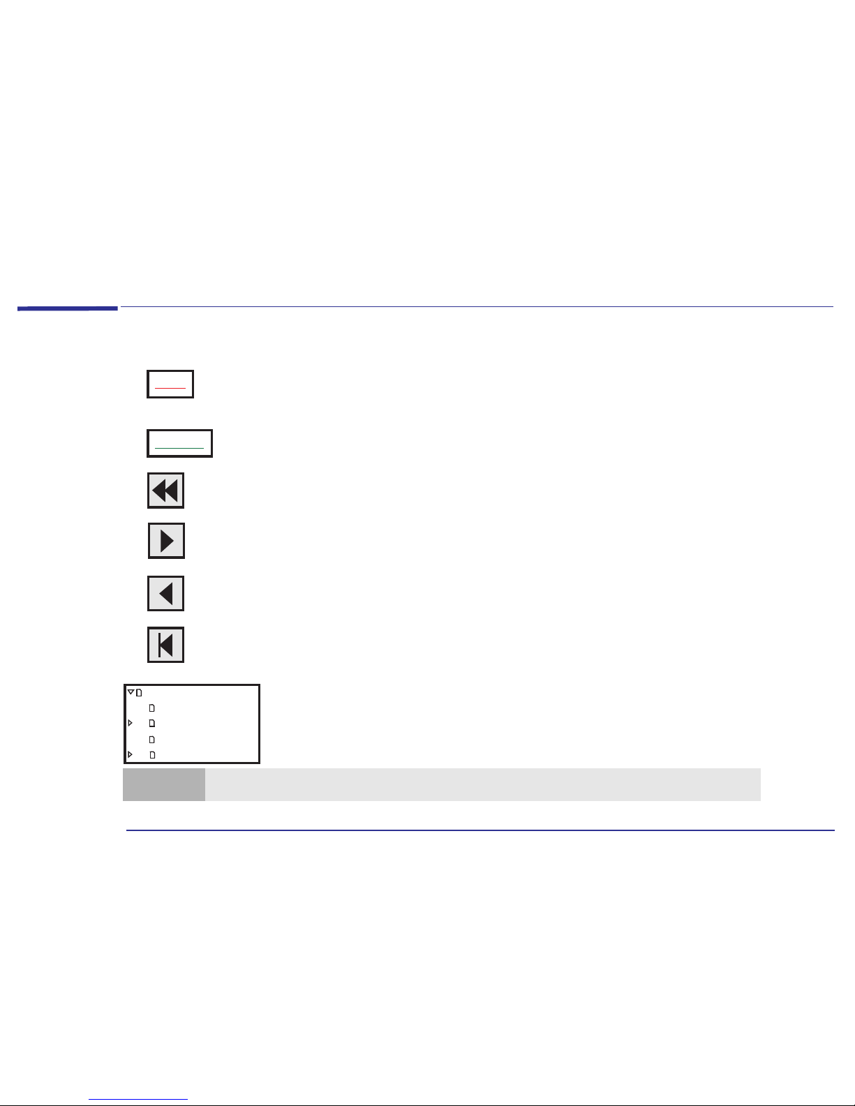
Click underlined red text to go to the topic indicated. Underlined red text is text that is “linked”
to another topic in the guide.
Click green text to go to the glossary, where a definition of the acronym is given.
Click the Go Back button in the toolbar to go back to your previous place in the guide.
Click the Next Page button in the toolbar to go to the next page in the guide.
Click the Previous Page button in the toolbar to go to the previous page in the guide.
Click the First Page button in the toolbar to go to the opening screen of the guide.
Click a bookmark name (to the left of the screen) to go to the topic corresponding to that
bookmark. Click the small triangle to the left of the bookmark to hide or show subordinate
bookmarks.
Topic
Acronym
Online Reference Guide
How to Use This Guide
Notice
About This Guide
Purpose ofThis Guide
Note
You can print this book, but only in landscape format.

3
Notice
Notice
The information contained in this document is subject to change without notice.
Hewlett-Packard makes no warranty of any kind with regard to this material, including, but not limited to, the implied
warranties of merchantability and fitness for a particular purpose. Hewlett-Packard shall not be liable for errors contained
herein or for incidental or consequential damages in connection with the furnishing, performance, or use of this material.
This document contains proprietary information that is protected by copyright. All rights are reserved. No part of this
document may be photocopied, reproduced, or translated to another language without the prior written consent of
Hewlett-Packard Company.
Microsoft®, MS-DOS® and Windows® are U.S. registered trademarks of Microsoft Corporation.
Zip
TM
is a trademark of Iomega Corporation.
Hewlett-Packard France
Grenoble Personal Computer Division
Technical Marketing
38053 Grenoble Cedex 9
France
1997 Hewlett-Packard Company

4
About This Guide
About This Guide
This Online Reference Guide is broken down into three main sections:
• About Your Hardware - information about the main hardware components that make up your computer: the system
board, your sound card, your keyboard, and so on.
• About Your BIOS - information about the set of programs that controls the input and output of data to peripherals.
• Upgrading and Adding Accessories - information about how to install new hardware components such as main memory
or expansion cards.
Purpose of This Guide
The purpose of this guide is to provide you with technical information about your computer. This is information that you
won’t need to reference every day, but which you will find useful if you ever want to upgrade or customize your
computer.

Contents
5
How to Use This Online Guide . . . . . . . . . . . . . . . . . . . . . . . . . . . . . . . . . . . . . . . . . . . . . . . . . . . . . . . . . . . . . . . 2
Notice. . . . . . . . . . . . . . . . . . . . . . . . . . . . . . . . . . . . . . . . . . . . . . . . . . . . . . . . . . . . . . . . . . . . . . . . . . . . . . . . . . . . 3
About This Guide . . . . . . . . . . . . . . . . . . . . . . . . . . . . . . . . . . . . . . . . . . . . . . . . . . . . . . . . . . . . . . . . . . . . . . . . . . 4
Purpose of This Guide . . . . . . . . . . . . . . . . . . . . . . . . . . . . . . . . . . . . . . . . . . . . . . . . . . . . . . . . . . . . . . . . . . . . . . 4
1 About Your Hardware
A Quick Look Inside Your Computer. . . . . . . . . . . . . . . . . . . . . . . . . . . . . . . . . . . . . . . . . . . . . . . . . . . . . . . . . 10
System Board Layout . . . . . . . . . . . . . . . . . . . . . . . . . . . . . . . . . . . . . . . . . . . . . . . . . . . . . . . . . . . . . . . . . 10
Main Components and Features of the System Board . . . . . . . . . . . . . . . . . . . . . . . . . . . . . . . . . . . . . . . 11
Expansion Card Slots . . . . . . . . . . . . . . . . . . . . . . . . . . . . . . . . . . . . . . . . . . . . . . . . . . . . . . . . . . . . . . . . . 12
System Board Configuration Jumpers . . . . . . . . . . . . . . . . . . . . . . . . . . . . . . . . . . . . . . . . . . . . . . . . . . . . 12
Your Sound Card. . . . . . . . . . . . . . . . . . . . . . . . . . . . . . . . . . . . . . . . . . . . . . . . . . . . . . . . . . . . . . . . . . . . . . . . . . 13
Connecting Audio Devices to the Rear Panel . . . . . . . . . . . . . . . . . . . . . . . . . . . . . . . . . . . . . . . . . . . . . . 14
Connecting Audio Devices to the Internal Connectors . . . . . . . . . . . . . . . . . . . . . . . . . . . . . . . . . . . . . . 15
Power Consumption. . . . . . . . . . . . . . . . . . . . . . . . . . . . . . . . . . . . . . . . . . . . . . . . . . . . . . . . . . . . . . . . . . . . . . . 16
Typical Power Consumption/Availability. . . . . . . . . . . . . . . . . . . . . . . . . . . . . . . . . . . . . . . . . . . . . . . . . . 16

6
Your HP Enhanced Keyboard. . . . . . . . . . . . . . . . . . . . . . . . . . . . . . . . . . . . . . . . . . . . . . . . . . . . . . . . . . . . . . . 17
Using the Enhanced Keys . . . . . . . . . . . . . . . . . . . . . . . . . . . . . . . . . . . . . . . . . . . . . . . . . . . . . . . . . . . . . . 18
Configuring Keyboard Shortcut Keys . . . . . . . . . . . . . . . . . . . . . . . . . . . . . . . . . . . . . . . . . . . . . . . . . . . . . 19
2 About Your BIOS
The BIOS in Your Computer. . . . . . . . . . . . . . . . . . . . . . . . . . . . . . . . . . . . . . . . . . . . . . . . . . . . . . . . . . . . . . . . 22
The HP Setup Program . . . . . . . . . . . . . . . . . . . . . . . . . . . . . . . . . . . . . . . . . . . . . . . . . . . . . . . . . . . . . . . . . . . . 23
Working Within the Setup Program . . . . . . . . . . . . . . . . . . . . . . . . . . . . . . . . . . . . . . . . . . . . . . . . . . . . . . 24
Boot Device Priority . . . . . . . . . . . . . . . . . . . . . . . . . . . . . . . . . . . . . . . . . . . . . . . . . . . . . . . . . . . . . . . . . . 25
Saving Your Changes and Leaving Setup . . . . . . . . . . . . . . . . . . . . . . . . . . . . . . . . . . . . . . . . . . . . . . . . . . 25
Protecting Your Computer . . . . . . . . . . . . . . . . . . . . . . . . . . . . . . . . . . . . . . . . . . . . . . . . . . . . . . . . . . . . . . . . . 26
Restricting Access to Your Computer - Setting a Password . . . . . . . . . . . . . . . . . . . . . . . . . . . . . . . . . . . 26
Power Management in the BIOS . . . . . . . . . . . . . . . . . . . . . . . . . . . . . . . . . . . . . . . . . . . . . . . . . . . . . . . . . . . . 27
Checking Your Configuration. . . . . . . . . . . . . . . . . . . . . . . . . . . . . . . . . . . . . . . . . . . . . . . . . . . . . . . . . . . . . . . 28
Warning Messages and the Power-On Self-Test (POST). . . . . . . . . . . . . . . . . . . . . . . . . . . . . . . . . . . . . . . . . 29
Beep Codes . . . . . . . . . . . . . . . . . . . . . . . . . . . . . . . . . . . . . . . . . . . . . . . . . . . . . . . . . . . . . . . . . . . . . . . . . 29

7
How to Recover if Things Go Wrong. . . . . . . . . . . . . . . . . . . . . . . . . . . . . . . . . . . . . . . . . . . . . . . . . . . . . . . . . 30
System Boot Failure. . . . . . . . . . . . . . . . . . . . . . . . . . . . . . . . . . . . . . . . . . . . . . . . . . . . . . . . . . . . . . . . . . . 30
Incorrect Password on Startup . . . . . . . . . . . . . . . . . . . . . . . . . . . . . . . . . . . . . . . . . . . . . . . . . . . . . . . . . . 30
Clearing the CMOS Configuration. . . . . . . . . . . . . . . . . . . . . . . . . . . . . . . . . . . . . . . . . . . . . . . . . . . . . . . . 31
3 Upgrading and Adding Accessories
Why Upgrade? . . . . . . . . . . . . . . . . . . . . . . . . . . . . . . . . . . . . . . . . . . . . . . . . . . . . . . . . . . . . . . . . . . . . . . . . . . . 34
Upgrades and Accessories You Can Install. . . . . . . . . . . . . . . . . . . . . . . . . . . . . . . . . . . . . . . . . . . . . . . . . 35
Upgrading the BIOS. . . . . . . . . . . . . . . . . . . . . . . . . . . . . . . . . . . . . . . . . . . . . . . . . . . . . . . . . . . . . . . . . . . . . . . 36
Upgrading Hardware . . . . . . . . . . . . . . . . . . . . . . . . . . . . . . . . . . . . . . . . . . . . . . . . . . . . . . . . . . . . . . . . . . . . . . 37
Removing and Replacing the Cover . . . . . . . . . . . . . . . . . . . . . . . . . . . . . . . . . . . . . . . . . . . . . . . . . . . . . . 37
Upgrading Main Memory . . . . . . . . . . . . . . . . . . . . . . . . . . . . . . . . . . . . . . . . . . . . . . . . . . . . . . . . . . . . . . . 39
Upgrading Video Memory . . . . . . . . . . . . . . . . . . . . . . . . . . . . . . . . . . . . . . . . . . . . . . . . . . . . . . . . . . . . . . 42
Upgrading a Processor. . . . . . . . . . . . . . . . . . . . . . . . . . . . . . . . . . . . . . . . . . . . . . . . . . . . . . . . . . . . . . . . . 45
Adding Accessories . . . . . . . . . . . . . . . . . . . . . . . . . . . . . . . . . . . . . . . . . . . . . . . . . . . . . . . . . . . . . . . . . . . . . . . 49
Adding Expansion Cards . . . . . . . . . . . . . . . . . . . . . . . . . . . . . . . . . . . . . . . . . . . . . . . . . . . . . . . . . . . . . . . 49
Installing Storage Devices . . . . . . . . . . . . . . . . . . . . . . . . . . . . . . . . . . . . . . . . . . . . . . . . . . . . . . . . . . . . . . 56
Changing the Battery. . . . . . . . . . . . . . . . . . . . . . . . . . . . . . . . . . . . . . . . . . . . . . . . . . . . . . . . . . . . . . . . . . . . . . 65

8
Appendix AT Commands
Basic AT Commands . . . . . . . . . . . . . . . . . . . . . . . . . . . . . . . . . . . . . . . . . . . . . . . . . . . . . . . . . . . . . . . . . . . . . . 68
Modem Response Messages . . . . . . . . . . . . . . . . . . . . . . . . . . . . . . . . . . . . . . . . . . . . . . . . . . . . . . . . . . . . . . . . 73
Glossary . . . . . . . . . . . . . . . . . . . . . . . . . . . . . . . . . . . . . . . . . . . . . . . . . . . . . . . . . . . . . . . . . . . . . . . . . 77
Index. . . . . . . . . . . . . . . . . . . . . . . . . . . . . . . . . . . . . . . . . . . . . . . . . . . . . . . . . . . . . . . . . . . . . . . . . . . . 81

1
About Your Hardware
10
1 About Your Hardware
A Quick Look Inside Your Computer
A Quick Look Inside Your Computer
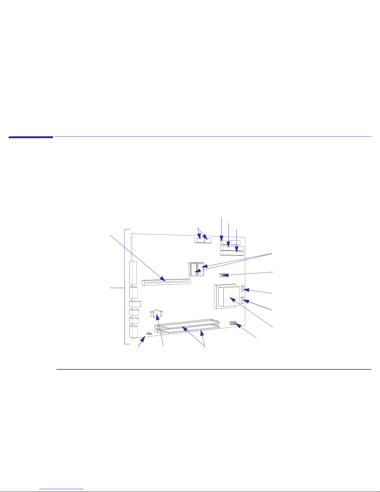
System Board Layout
The following system board block diagram will help you identify where the different components and connections are
located on the board.
Rear Panel
Connectors
Battery
Power Connectors
(to power supply)
Processor
Clear CMOS
Jumper Strip
Video Memory
Upgrade Sockets
Main Memory Modules
and Sockets
Secondary IDE Connector (eg, for a CD-ROM drive and a Zip drive)
Primary IDE Connector (eg, for two hard disk drives)
Floppy Disk Drive Connector (for two drives)
Backplane
Connector
Front Bezel
Fan Connector
Jumper Strip JP4 Processor Voltage
Jumper Strip JP5 Processor/Bus Speed
Status Panel
Connector

11
1 About Your Hardware
A Quick Look Inside Your Computer
Main Components and Features of the System Board
The main components and features of your HP Brio PC are:
• Fast IDE controller with two channels on the PCI bus:
❒ A primary IDE channel. For example, used for one or two IDE hard disk drives.
❒ A secondary IDE channel. For example, used for IDE CD-ROM drives, IDE hard disk drives, or IDE zip drives.
• Floppy Disk Drive controller supporting two devices.
• Rear panel connectors:
❒ One mouse socket
❒ One keyboard socket
❒ One display connector
❒ One Universal Serial Bus (USB) connector
❒ One parallel port
❒ One serial port
• Keyboard/mouse controller and interface.
• Two main memory sockets (168-pin SDRAM DIMM), allowing installation of up to 128 MB of main memory
(2 x 64 MB). The slots can be filled in any order.
• 1 or 2 MB of video memory on the system board. If the computer has 1 MB of video memory, it can be upgraded to 2 MB.
• 512 KB of level two cache memory (SRAM) soldered on the system board.

12
1 About Your Hardware
A Quick Look Inside Your Computer
Expansion Card Slots
There are five expansion card slots on the backplane for the installation of:
• Two 32-bit PCI cards and three 16-bit ISA cards,
or
• Three 32-bit PCI cards and two 16-bit ISA cards.
System Board Configuration Jumpers
Microprocessor
Configuration
Jumper (JP5)
This jumper allows the system board to be set so that it matches the speed of the installed processor. You only need to
change the microprocessor configuration jumper if you install a new processor that has a different processor speed to the
one that is currently installed.
Refer to “
Upgrading a Processor” on page 45 for more information about installing a processor upgrade, and changing the
jumper settings.
CPU Voltage
Jumper (JP4)
Use this jumper to change the output of the on-board switching voltage regulator for different processors. Refer to
“
Upgrading a Processor” on page 45 for more information about installing a processor upgrade, and changing the jumper
settings.
CMOS Jumper The CMOS memory stores information, such as your computer’s configuration, which is preserved when you turn off your
computer. A jumper placed on pins 1-2 prevents changes to the CMOS configuration. This is the default setting. Refer to
“
Clearing the CMOS Configuration” on page 31 for information about clearing the CMOS and using this jumper.
Note
PCI expansion card slots are generally white plastic grooves.
ISA expansion card slots are generally black plastic grooves lined with silver.
13
1 About Your Hardware
Your Sound Card
Your Sound Card
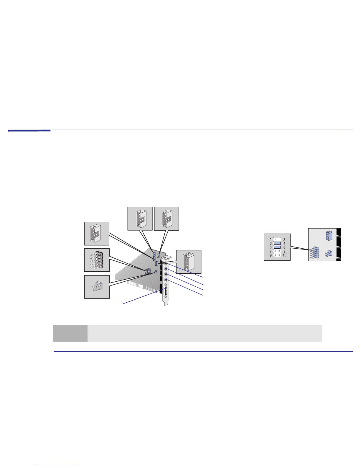
Depending on the computer you have purchased, a sound card may be already installed. The sound card has several
connectors that allow you to connect the card to other devices. This figure shows where the connectors are located on
the sound card.
Note
The internal connectors Internal Speaker Connector, Multimedia Control Panel Connector, Telephone Answering
Device Connector and Multimedia Control Panel Microphone Connector are not used on this computer.
Multimedia
Control Panel
Connector (refer
to note below)
AUX In Connector
(refer to page 15 )
CD Audio Connector
(refer to page 15 )
Internal Speaker
Connector (refer
to note below)
Telephone Answering
Device Connector
(refer to note below)
Multimedia Control
Panel Microphone
Connector (refer to
note below)
Jumpers are required between pins 3 and
4 and between pins 5 and 6 of the
Multimedia Control Panel Connector.
Without these jumpers, the sound card
will not output sound through the rear
panel. (These jumper connections are set
by default).
Line In
Mic
Line Out
SPK
MIDI / Game
Refer to page 14 for details about the sound card’s rear panel

14
1 About Your Hardware
Your Sound Card
Connecting Audio Devices to the Rear Panel
You can connect external speakers, a microphone, or other audio devices to the rear panel. Do not connect headphones
to the jack on the CD-ROM drive as this will let you hear output only from music CDs. Through the rear panel jack on
your computer you can hear sounds from training presentations, MIDI music files, any other audio software, and music
CDs too.
Details of what each jack on the sound card is used for are given below.
LINE IN Connect devices such as a cassette, DAT, or Minidisc player for playback and recording.
MIC Connect a microphone for voice input.
LINE OUT Bypass the sound card’s internal amplifier to connect powered speakers, an external amplifier for audio
output, or a recording device (tape deck) or stereo headphones.
You can use this jack for headphones with limited power output. You can also use it with amplified
speakers which have a dedicated headphone jack for this purpose.
SPK Connect speakers for audio output from the card’s built-in power amplifier. Adjust the volume from within
the software or from the multimedia control panel if this feature is available on your computer.
MIDI/GAME Connect a joystick (for game software) or MIDI instrument. The MIDI port is disabled by default. You will
have to enable this port if you wish to use it with a MIDI.
Warning
Before connecting headphones or speakers, always turn the volume down to avoid discomfort from unexpected noise
or static. Listening to loud sounds for prolonged periods of time may permanently damage your hearing. Before
putting on headphones, place them around your neck and turn the volume down. Then, put on the headphones and
slowly increase the volume by using the Audio Mixer Applet or the enhanced keyboard until you find a comfortable
listening level, where the sound is clear, without being too loud. When you can hear comfortably and clearly, without
distortion, leave the volume control in that position.
Warning
The SPK jack is for a highly amplified output and is therefore not suitable for connecting headphones.
15
1 About Your Hardware
Your Sound Card
Connecting Audio Devices to the Internal Connectors
There are also several internal connectors located on the sound card itself. These are shown on page 13 , and those that
are used are described below.
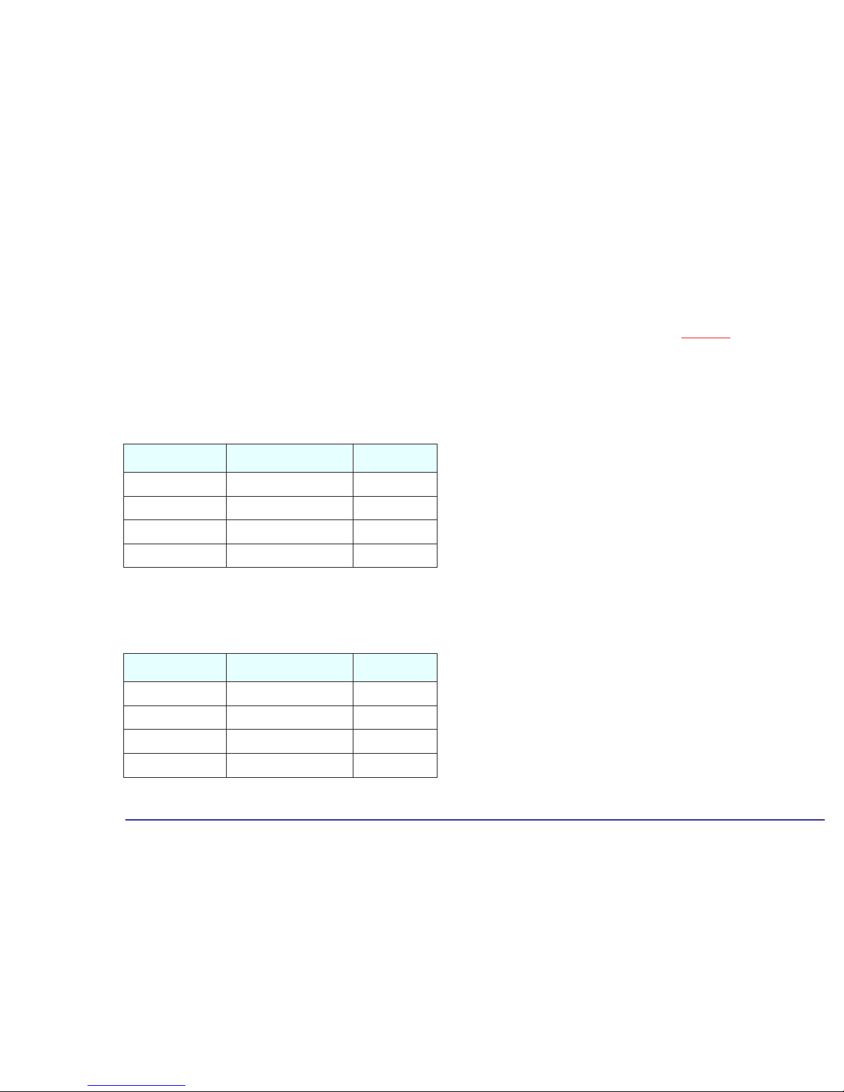
AUX In Connector This Auxiliary Connector allows you to connect an additional internal audio source such as a TV tuner, or another similar
card. It can also be used to accept decompressed audio data from an MPEG video card. The AUX In connector has the
following pin assignments:
CD Audio Connector The CD Audio Connector, labeled “CDAUDIO”, allows you to connect the sound card to the CD-ROM drive via the audio
cable, so that you can listen to audio from the CD-ROM drive. The CD Audio Connector has the following pin
assignments:
Pin Signal I/O
1 Analog Ground -
2 AUX right channel IN
3 Analog Ground 4 AUX left channel IN
Pin Signal I/O
1 Analog Ground 2 CD right channel IN
3 Analog Ground -
4 CD left channel IN
16
1 About Your Hardware
Power Consumption
Power Consumption
1. The power supply in your HP Brio PC continues to supply power to the CMOS memory, even when turned off.
Typical Power Consumption/Availability
There is a maximum per-slot limit of 25 W between all supply rails.
Note
The figures given below are valid for computers with a standard configuration—no expansion cards and no CD-ROM
drive. For certain configurations, the power consumption values will be higher.
Full Power Mode
<44 W
Suspend Mode
<30 W
Off
<3 W
1
Note
When the computer is turned off with the power button on the front panel, the power consumption falls below 3 W,
but it is not zero. The special on/off method used by this computer considerably extends the lifetime of the power
supply. To reach zero power consumption in “off” mode, either unplug the computer from the power outlet or use a
power block with a switch.
ISA Expansion Card Slots
PCI Expansion Card Slots
+ 5 V
4.5 A limit per slot (limited by system board)
+ 5 V
4.5 A maximum per slot
+ 12 V
1.5 A limit per slot (limited by system board)
+ 12 V
0.5 A maximum per slot
- 5 V
0.1 A total power limit (limited by power supply)
- 12 V
0.1 A maximum per slot
- 12 V
0.3 A total power limit (limited by power supply)
17
1 About Your Hardware
Your HP Enhanced Keyboard
Your HP Enhanced Keyboard
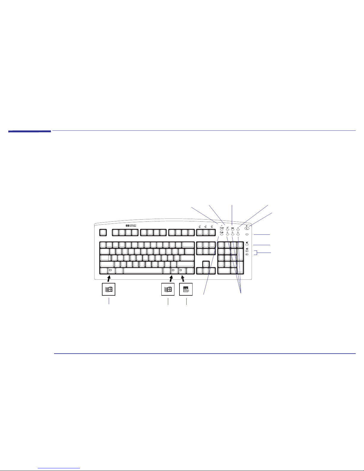
Depending on the computer you have purchased, you may have the HP Enhanced Keyboard. As well as offering standard
keys, the HP Enhanced Keyboard allows you direct access to various software applications. You can also create your own
shortcuts to your most frequent tasks by configuring certain keys. For example, you can configure your keyboard so that
you can access your word processor application at the touch of a key.
Messages key, with
mail LED
HP Brio
Center
WEB browser Menu key
Suspend key
Mute
Volume control
Phone key
Shortcut keys
Information
Display the Windows Start menu by pressing
either of the two Windows keys.
Access the right-mousebutton functions.
18
1 About Your Hardware
Your HP Enhanced Keyboard
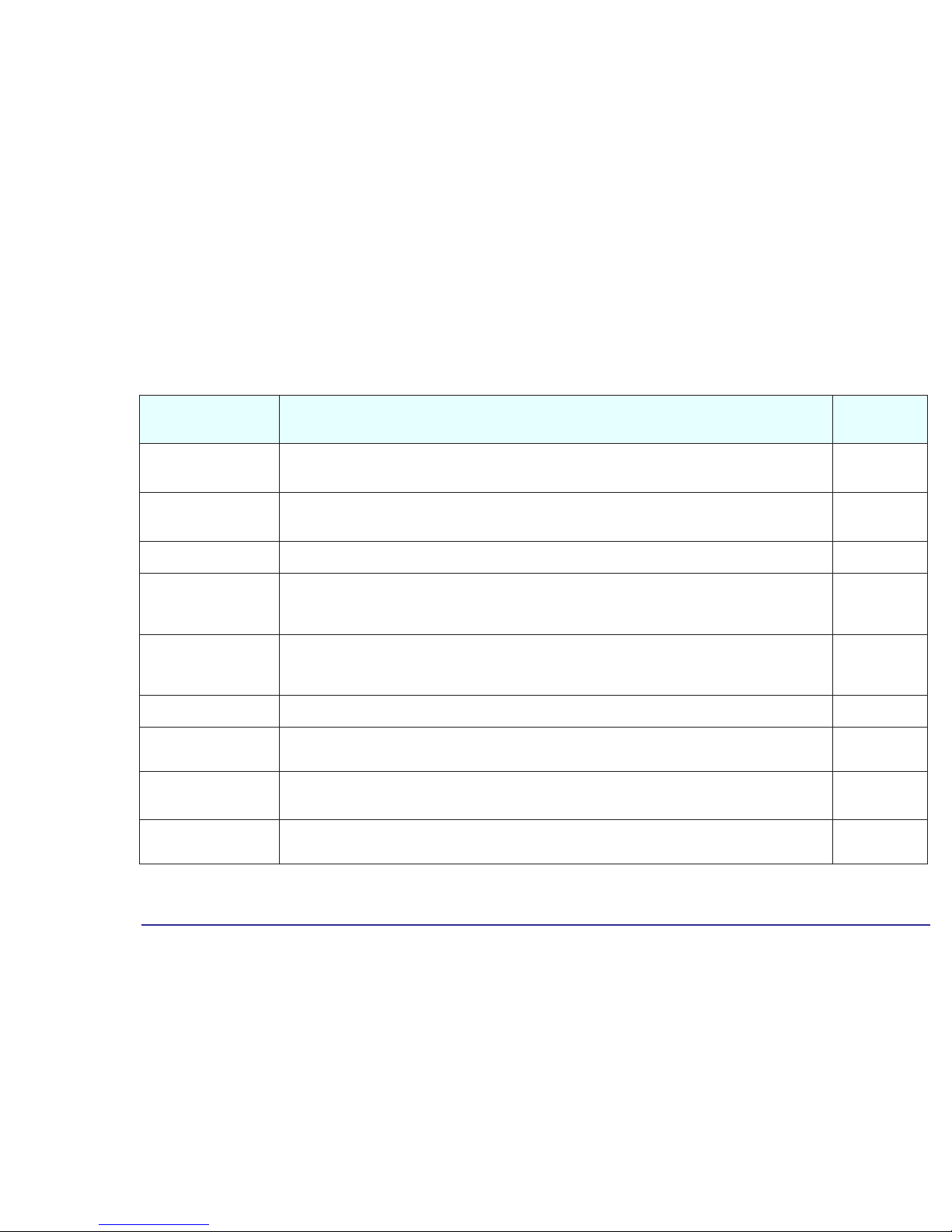
Using the Enhanced Keys
These keys are located on the top right-hand side of the keyboard and can be used as follows:
Key Function
Configurable
Key?
Messages and LED
Monitors the arrival of fax messages or electronic mail. The LED blinks when a new fax or E-mail arrives. The LED is
turned off when you open the message. Press this key to launch your e-mail application.
Yes. refer to
page 19
HP Brio Center
Accesses the HP Brio Center. No
Web Browser
Launches the default Internet browser configured in your system. No
Menu
Displays the current configuration of the keys and the actions mapped to them. Pressing the Menu key again closes
this window without further action needed. Pressing any other extended key closes the window and launches the
associated command.
No
Suspend
This key can be used to either turn on power saving capabilities, if configured in the Control Panel, or start the
screen saver. It is recommended that you configure your screen saver with a password to lock the computer when
the screen saver is activated. A screen saver will not be cleared until the correct password has been typed.
No
Information
Accesses the information section of the HP Brio Center. No
Mute and Volume Control
Press the Mute key to mute the audio. The volume keys are used to adjust the volume level. If no sound card is
installed in your computer, a warning will be displayed on the screen if one of these three keys is pressed.
No
Shortcuts
(S3, S4, S5)
You can assign these keys to start applications, open files, or open URLs on the Internet. For example, you can
access your word processor application at the touch of a single key. Requires an Internet connection.
Yes. Refer to
page 19
Phone
This key can be used to access telephone directory sites world-wide. To do this, however, you must have an Internet
connection. You can also configure this key in the same way as the shortcut keys.
Yes. Refer to
page 19
19
1 About Your Hardware
Your HP Enhanced Keyboard
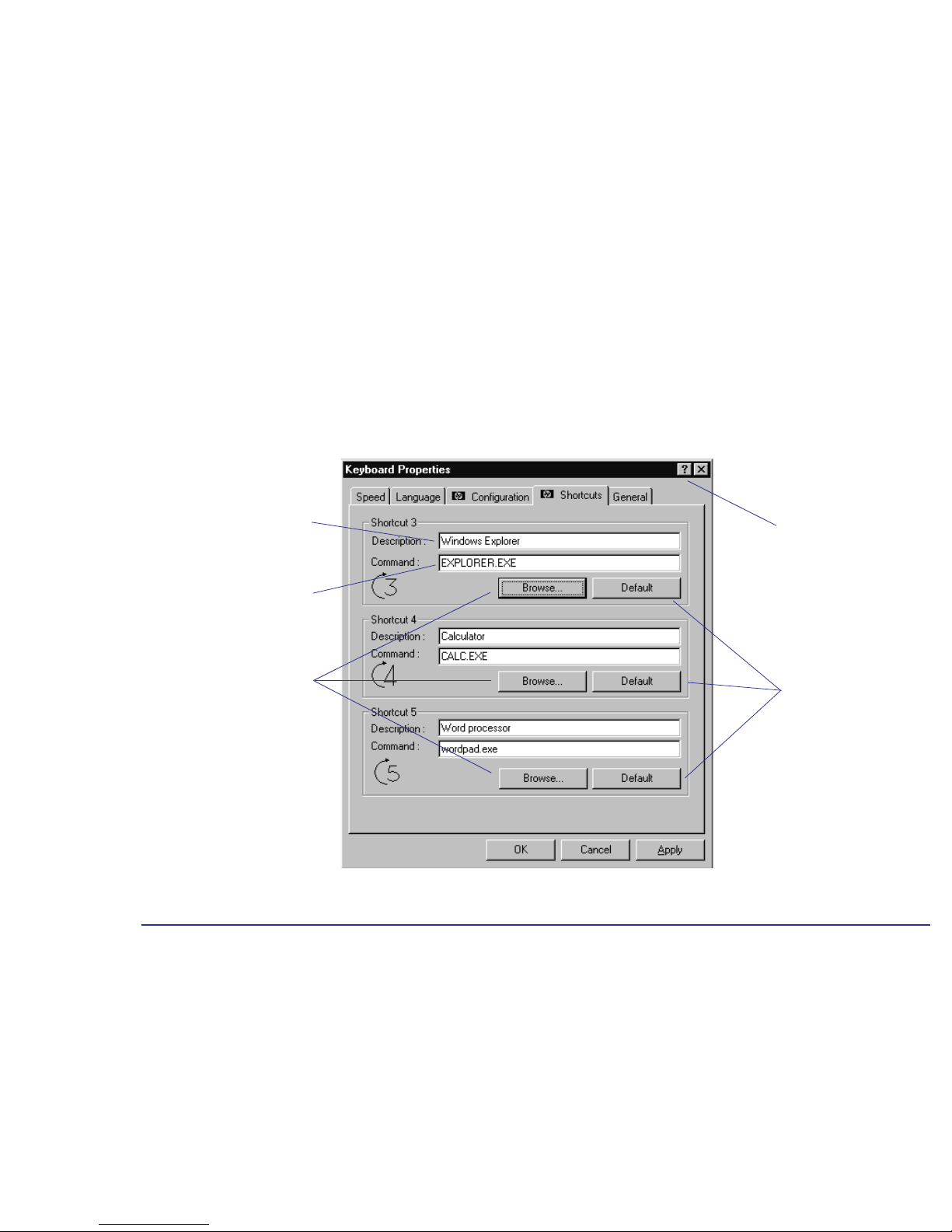
Configuring Keyboard Shortcut Keys
You have three standard configurable shortcut keys (S3, S4, S5). You can configure shortcut keys from the Control Panel.
Double-click the Keyboard icon, then select the Shortcuts tab from the Keyboard Properties screen. To define a Shortcut
key, you need to:
Click here to restore the
HP default settings.
Use the Browse button to
locate the file you want to use
in the Command field.
Click here to activate the
Question Mark pointer. Then
click any element to obtain
information.
Provide a Command, which is
the executable that starts the
application.
Provide a Description of the
application you are assigning to
the Shortcut key.
20
1 About Your Hardware
Your HP Enhanced Keyboard
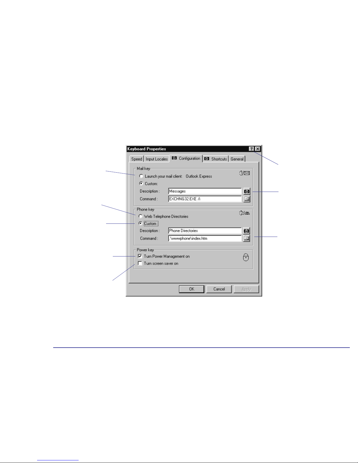
You can also reconfigure the mail, phone, and power keys on your keyboard. Double-click the Keyboard icon, then select
the Configuration tab from the Keyboard Properties screen.
Launch the screen saver when the
Suspend key is activated
1
.
Link to several telephone
directories world-wide.
Launch your default mail
client that has been
configured in your Internet
settings.
Click this button to restore the
default settings for the shortcut
key.
Reduce the power used by the
computer by putting it in
suspend mode. This option is
activated by pressing the
Suspend key
Click here to activate the
Question Mark pointer. Then
click any element to obtain
information.
1. The Turn Power Management on and
Turn screen saver on options can both be enabled at the same time
Click this button to browse
through the folders to locate
the file you want to use in the
Command field.
Create a link to your
frequently used telephone
directory on the Web.

2
About Your BIOS

22
2 About Your BIOS
The BIOS in Your Computer
The BIOS in Your Computer
What Is the BIOS? The BIOS has two main roles:
• It tests and configures the computer’s hardware components during the POST at power on, and lets you perform
further configuration by using the Setup program.
• It provides the link between the software running on your computer, which has been written to be independent of any
particular computer, and your computer’s hardware (the hard disk, the keyboard, the display, and so on).
The BIOS is part of the System ROM and is stored in a chip on the system board. A computer’s BIOS is specific to that
computer.
What Can I Do with
the BIOS?
You can configure certain aspects of your computer by using the Setup program which is part of the BIOS. Refer to “The
HP Setup Program” on page 23 for more information about the Setup program.

23
2 About Your BIOS
The HP Setup Program
The HP Setup Program
The built-in Setup program is accessed by pressing the key during the POST. Online help for an item on the Setup
screen can be obtained by highlighting the item (refer to page 24
for instructions on how to use the key functions). Help
is then displayed on the right of the screen. It is updated as you move the cursor to each field.
If you have any doubts about using the Setup program, contact your reseller for help.
The band along the top of the screen offers the following menus:
• Main: for basic system configuration.
• Advanced: for setting the Advanced Features available in the BIOS.
• Security: for setting a password to restrict access to your computer. For information on how to set a password, refer
to “
Restricting Access to Your Computer - Setting a Password” on page 26.
• Power: for selecting power-management modes to reduce the amount of energy used after specified periods of
inactivity.
• Boot: for selecting your boot device order and priority. Refer to “Boot Device Priority” on page 25.
• Exit: for leaving the Setup program. Refer to “Saving Your Changes and Leaving Setup” on page 25.
The Setup program changes system behavior by modifying the power-on initialization parameters. Setting incorrect
values may cause system boot failure. Should this occur, press the key while you are in the Setup program to load
the Setup program’s default values. This should enable the computer to boot properly.
HP strongly recommends that you make a note of any changes you make while in the Setup program.

24
2 About Your BIOS
The HP Setup Program
Working Within the Setup Program
The following key functions are available when using the Setup program.
• The or arrows can be used to select fields in the current menu.
• The key moves the cursor to the top item, and the key moves the cursor to the bottom item of the current
menu.
• The key displays a sub-menu for menu items marked with a solid right
arrow .
• The key or + keys allow you to exit from a sub-menu.
• The and arrows select menus from the menu bar.
• The key loads factory-installed default values.
• The key saves and exits from the Setup program.
• The key or + keys display the general help screen.
• The key exits from the general help screen.
Pressing the or arrows while you are on a main menu screen will take you to the next menu option. If,
however, you are on a sub-menu screen and you press these arrows, you will stay on that screen.
Use the and arrows to scroll through the items on the general help screen.
25
2 About Your BIOS
The HP Setup Program
Boot Device Priority
You can select the order of the devices from which the BIOS attempts to boot the operating system. During the POST, if
the BIOS is unsuccessful at booting from one device, it will try the next one on the Boot Device Priority list until an
operating system is found. The default boot device is the floppy disk. To speed up booting, you may wish to set the hard
disk as the default boot device. If you ever need to boot from a floppy though, remember to reset the floppy as the
default boot device.
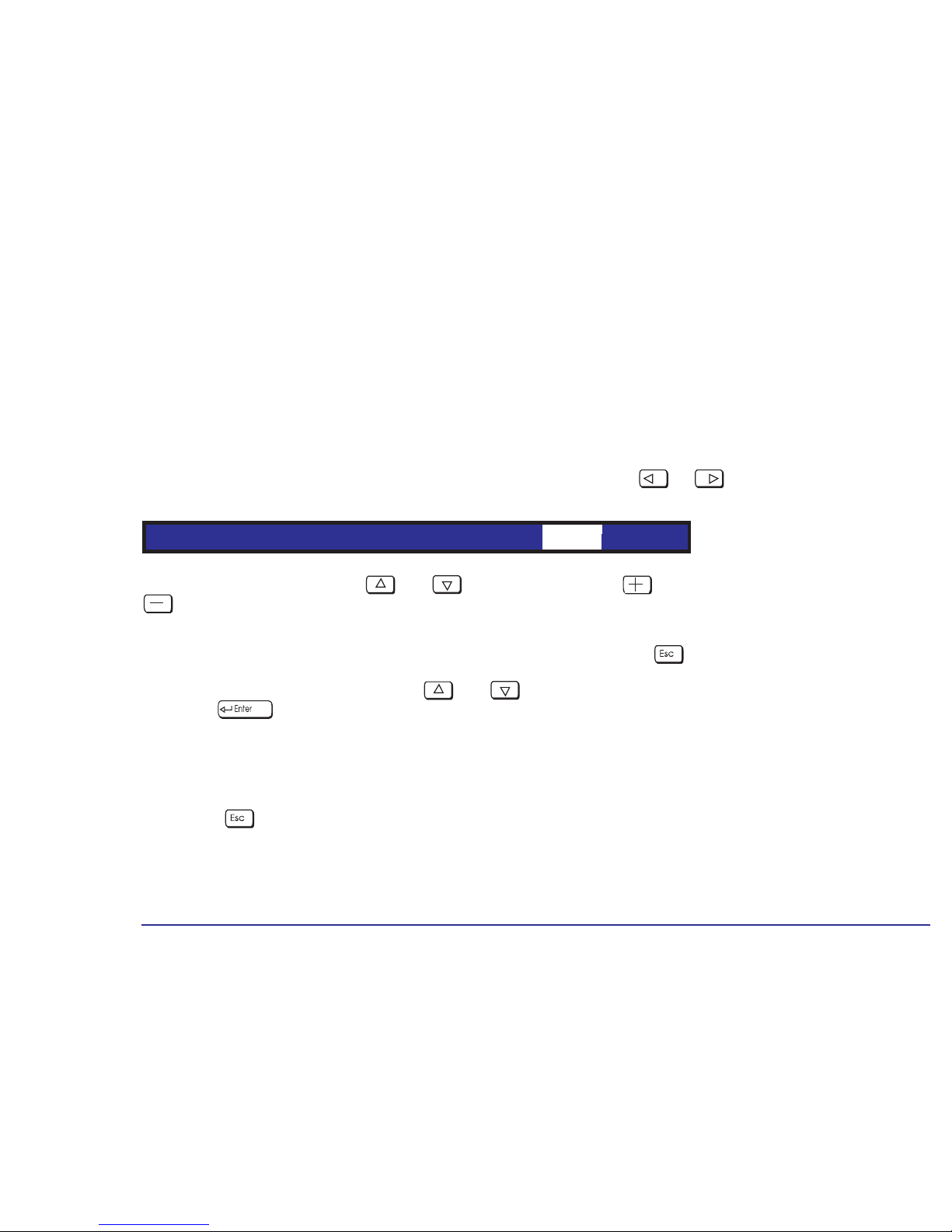
The Boot Device Priority can be changed through the Boot menu. Use the or arrows to move along the top
of the main menu bar to its location. The item is then highlighted and displays the available boot options.
To select the boot device, use the and arrows, then press the key to move the device up the list, or the
key to move it down the list.
Changing the Boot Device Priority for the current boot:
You can also change the boot order just for the current boot. To do this, press while the logo and the message
Press <F2> to enter SETUP are displayed during system startup. This initially displays the POST before displaying
the Boot Menu. On the Boot Menu use the and arrows to select the device from which you want to boot, and
then press . The computer then attempts to boot from the selected drive.
Saving Your Changes and Leaving Setup
When you have made all your changes, you must save them and exit Setup.
1 Press the key to enter the Exit menu.
2 Select Exit Saving Changes to save your changes and exit Setup.
The computer will automatically restart. If you set a password, the computer will display the power-on prompt. Enter the
User Password to use the computer.
Main PowerAdvanced Security ExitBoot

26
2 About Your BIOS
Protecting Your Computer
Protecting Your Computer
Restricting Access to Your Computer - Setting a Password
Setting a Password Set a password to protect your computer’s configuration by preventing access to the Setup menus. Full access to the
Setup menus will only be possible by using your password. To set a password:
1 Start the Setup Program. Refer to “The HP Setup Program” on page 23.
2 Select the Security menu group, then select the “Set Password” item.
3 You are asked to enter the password twice. Be sure to save your changes before you exit the Setup program.
Password on Boot Enabling a password entry on boot can provide a power-on password prompt to prevent your computer being started or
used in your absence. The password is entered when the POST has completed, before the computer finishes its normal
startup procedure. Password on Boot can only be enabled if a password has already been set. It should be noted that
this password option is not linked with your Windows operating system.
To enable a Password on Boot:
1 Start the Setup Program.
2 Select the Security menu group, then enable the “Password on Boot” item.
3 Be sure to save your changes before you exit the Setup program.
Note
It is recommended that you set a password that you can easily remember.
Note
After three unsuccessful attempts, your computer will be disabled. If this is the case, turn your computer off and
then on again, then enter the correct password. If you have forgotten your password, you need to clear the CMOS
configuration. Refer to page 31
for an explanation on how to clear the CMOS.
 Loading...