

Page 1

Advanced Setup Guide
Online Guide
Date: Autumn 1997
Page 2
How to Use This Online Guide
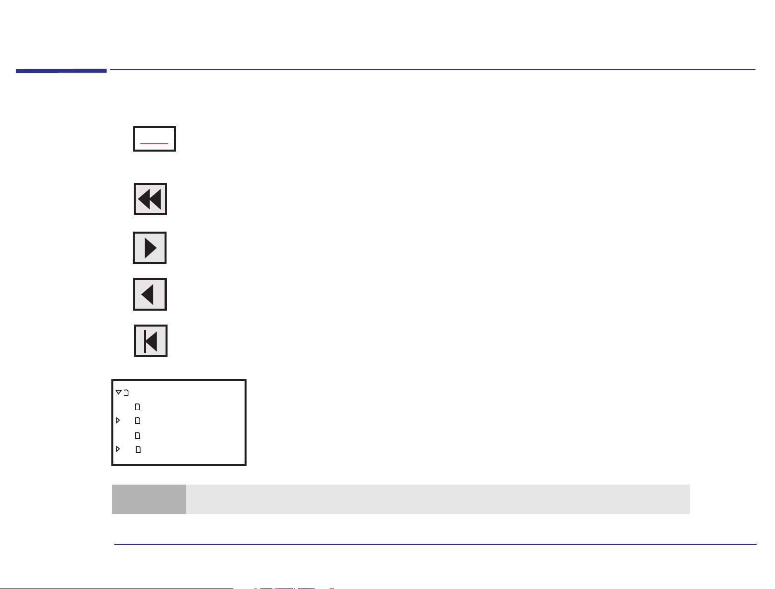
Click underlined red text to go to the topic indicated. Underlined red text is text that is “linked”
Topic
Click the Go Back button in the toolbar to go back to your previous place in the guide.
Click the Next Page button in the toolbar to go to the next page in the guide.
Click the Previous Page button in the toolbar to go to the previous page in the guide.
to another topic in the guide.
How to Use This Online Guide
Click the First Page button in the toolbar to go to the opening screen of the guide.
Advanced Setup Guide
How to use this
Notice
Contents
Introducing the Adva
Note
You can print this book, but only in landscape format.
Click a bookmark name (to the left of the screen) to go to the topic corresponding to that
bookmark. Click the small triangle to the left of the bookmark to hide or show subordinate
bookmarks.
2
Page 3

Notice
Notice
The information contained in this document is subject to change without notice.
Hewlett-Packard makes no warranty of any kind with regard to this material, including, but not limited to, the implied
warranties of merchantability and fitness for a particular purpose. Hewlett-Packard shall not be liable for errors contained
herein or for incidental or consequential damages in connection with the furnishing, performance, or use of this material.
This document contains proprietary information that is protected by copyright. All rights are reserved. No part of this
document may be photocopied, reproduced, or translated to another language without the prior written consent of
Hewlett-Packard Company.
CompuServe
Microsoft, MS-DOS and Windows are U.S. registered trademarks of Microsoft Corporation.
Hewlett-Packard France
Grenoble Personal Computer Division
Technical Marketing
38053 Grenoble Cedex 9
France
is a U.S. trademark of CompuServe, Inc.
1997 Hewlett-Packard Company
3
Page 4

Page 5

Advanced Setup Guide
Advanced Setup Guide
Page 6

The HP PC
The HP PC provides the following components and features:
System Board
• Enhanced IDE (Integrated Drive Electronics) controller with two channels on the PCI bus:
❒ A primary IDE channel for two IDE hard disk drives.
❒ A secondary IDE channel for an IDE CD-ROM drive or a IDE hard disk drive.
• Rear panel connectors:
❒ 1 mouse socket
❒ 1 keyboard socket
❒ 1 display connector
❒ 1 Universal Serial Bus (USB) connector
❒ 1 parallel port
❒ 1 serial port
The HP PC
• Keyboard/mouse controller and interface.
• Four memory module sockets for DRAM main memory, allowing installation of up to 128 MB.
• 1 MB Integrated video memory on the system board, upgradeable to 2MB.
• System ROM (using flash ROM technology) that can be easily updated with the latest firmware, using the Phlash.exe
program supplied with the firmware upgrade.
6
Page 7

The HP PC
The system ROM contains:
❒ The BIOS (system BIOS, video BIOS and low-option ROM).
❒ The menu-driven Setup program with context-sensitive help
(in U.S. English only).
• Energy Star-compliant power management.
All PCs described in this manual have a power-saving capability in accordance with the Energy Star guidelines (U.S.
Environmental Protection Agency). Nevertheless, it is possible that some configurations (e.g. fully loaded multi-media
models) use slightly more than 30W in sleep mode, which is the limit required for obtaining the Energy Star label.
Inclusion of the Energy Star label indicates that your PC is Energy Star-compliant.
Backplane
Five expansion card slots for the installation of:
❒ Two 32-bit PCI (Peripheral Component Interconnect) cards
and three 16-bit ISA (Industry Standard Architecture) cards,
or
❒ Three 32-bit PCI cards and two 16-bit ISA cards.
Preinstalled Software
Your HP PC is preinstalled with the following operating software:
• BIOS: Phoenix.
• Operating system: On most models, Windows 95 is provided. This operating system provides: configuration tools, Plug
and Play mode, and many other features.
• Depending on the model you have purchased, your computer may also include: business applications, communication
software, and a range of information sources, tools, and utilities to better tailor your PC to suit your needs.
7
Page 8

Associated Documentation
Associated Documentation
The following HP publications may also assist the reader of this manual:
• Communications - paper book providing guidance on how to set up your communications software.
• Getting Support - paper book explaining how to obtain HP support. The book also contains safety and warranty
information.
• Questions & Answers - paper document that answers your most commonly asked questions.
• Upgrade Guide - online book explaining how to upgrade your PC.
• Learning About Your HP PC - online help giving information about your computer.
For a list of available documentation, double-click the HP Guide to Documentation icon on the desktop, or press
the Information key on your keyboard.
If your PC is up and running but you are experiencing some problems, refer to the online support center on page 9 .
8
Page 9

HP Centers
HP Centers
Double-click the icon on the desktop, or click the Start menu and then HP Centers, or press the key on
your keyboard, to open the HP Centers window.
Once you have opened the HP Centers window you can access and use the following centers:
• Communications - communicate easily with the outside world
enable/disable fax reception, set up your answering machine, dial a phone number, and listen to your voice messages.
1
. You can set up your fax program, send a fax,
• Data Protection - make sure your data is secure and protected. You can protect your PC from viruses, back up your
data, maintain your hard disk (for example, scan it for errors), and restrict access to your PC.
• Network - share and access local network resources
CD-ROM drives, Internet connections, and so on.
2
. You can share and access printers, folders and files, fax modems,
• Welcome - discover what you can do with your PC and how to personalize it. You can register your PC, check your PC
settings, follow a PC tour, and see what documentation is available to you.
• Support - solve computer problems with the support tools and services provided by HP. You can diagnose hardware
problems, recover software applications that were preinstalled on your PC, access HP online support services, and run
Windows 95 troubleshooting tools.
1. Communications features are only available on communications models.
2. To use a local area network (LAN), you need to install a network card and software.
9
Page 10

HP Centers
10
Page 11

Contents
1 Introducing the Advanced Setup Guide
How to Use This Online Guide . . . . . . . . . . . . . . . . . . . . . . . . . . . . . . . . . . . . . . . . . . . . . . . . . . . . . . . . . . . . . . . 2
Notice. . . . . . . . . . . . . . . . . . . . . . . . . . . . . . . . . . . . . . . . . . . . . . . . . . . . . . . . . . . . . . . . . . . . . . . . . . . . . . . . . . . . 3
The HP PC . . . . . . . . . . . . . . . . . . . . . . . . . . . . . . . . . . . . . . . . . . . . . . . . . . . . . . . . . . . . . . . . . . . . . . . . . . . . . . . . 6
Associated Documentation . . . . . . . . . . . . . . . . . . . . . . . . . . . . . . . . . . . . . . . . . . . . . . . . . . . . . . . . . . . . . . . . . . 8
HP Centers. . . . . . . . . . . . . . . . . . . . . . . . . . . . . . . . . . . . . . . . . . . . . . . . . . . . . . . . . . . . . . . . . . . . . . . . . . . . . . . . 9
Purpose of the Guide . . . . . . . . . . . . . . . . . . . . . . . . . . . . . . . . . . . . . . . . . . . . . . . . . . . . . . . . . . . . . . . . . . . . . . 18
The HP Setup Program. . . . . . . . . . . . . . . . . . . . . . . . . . . . . . . . . . . . . . . . . . . . . . . . . . . . . . . . . . . . . . . . 18
System Board Layout . . . . . . . . . . . . . . . . . . . . . . . . . . . . . . . . . . . . . . . . . . . . . . . . . . . . . . . . . . . . . . . . . . . . . . 19
CMOS Jumper (JP6). . . . . . . . . . . . . . . . . . . . . . . . . . . . . . . . . . . . . . . . . . . . . . . . . . . . . . . . . . . . . . . . . . 20
2 Protecting and Using Your PC
Security Features . . . . . . . . . . . . . . . . . . . . . . . . . . . . . . . . . . . . . . . . . . . . . . . . . . . . . . . . . . . . . . . . . . . . . . . . . 22
HP Setup Program . . . . . . . . . . . . . . . . . . . . . . . . . . . . . . . . . . . . . . . . . . . . . . . . . . . . . . . . . . . . . . . . . . . 22
Protecting Your PC from Virus Infections . . . . . . . . . . . . . . . . . . . . . . . . . . . . . . . . . . . . . . . . . . . . . . . . . 22
Maintaining Your Disk and Files. . . . . . . . . . . . . . . . . . . . . . . . . . . . . . . . . . . . . . . . . . . . . . . . . . . . . . . . . . . . . 23
Improving File Access Time . . . . . . . . . . . . . . . . . . . . . . . . . . . . . . . . . . . . . . . . . . . . . . . . . . . . . . . . . . . . 23
Increasing Disk Space. . . . . . . . . . . . . . . . . . . . . . . . . . . . . . . . . . . . . . . . . . . . . . . . . . . . . . . . . . . . . . . . . 24
11
Page 12

Using Power Management in Windows 95 . . . . . . . . . . . . . . . . . . . . . . . . . . . . . . . . . . . . . . . . . . . . . . . . . . . . 25
Enhanced Keyboard . . . . . . . . . . . . . . . . . . . . . . . . . . . . . . . . . . . . . . . . . . . . . . . . . . . . . . . . . . . . . . . . . . . . . . 27
Configuring Shortcut Keys . . . . . . . . . . . . . . . . . . . . . . . . . . . . . . . . . . . . . . . . . . . . . . . . . . . . . . . . . . . . . 29
3 The HP Setup Program
HP/Phoenix BIOS Description . . . . . . . . . . . . . . . . . . . . . . . . . . . . . . . . . . . . . . . . . . . . . . . . . . . . . . . . . . . . . . 32
Power-On Self-Test (POST) . . . . . . . . . . . . . . . . . . . . . . . . . . . . . . . . . . . . . . . . . . . . . . . . . . . . . . . . . . . . 32
Beep Codes . . . . . . . . . . . . . . . . . . . . . . . . . . . . . . . . . . . . . . . . . . . . . . . . . . . . . . . . . . . . . . . . . . . . . . . . . 32
HP Setup Program . . . . . . . . . . . . . . . . . . . . . . . . . . . . . . . . . . . . . . . . . . . . . . . . . . . . . . . . . . . . . . . . . . . . . . . . 34
HP Setup Key Functions . . . . . . . . . . . . . . . . . . . . . . . . . . . . . . . . . . . . . . . . . . . . . . . . . . . . . . . . . . . . . . . 35
Boot Device Priority . . . . . . . . . . . . . . . . . . . . . . . . . . . . . . . . . . . . . . . . . . . . . . . . . . . . . . . . . . . . . . . . . . 36
Summary Screen . . . . . . . . . . . . . . . . . . . . . . . . . . . . . . . . . . . . . . . . . . . . . . . . . . . . . . . . . . . . . . . . . . . . . 36
Setting Passwords . . . . . . . . . . . . . . . . . . . . . . . . . . . . . . . . . . . . . . . . . . . . . . . . . . . . . . . . . . . . . . . . . . . . 36
Power Management in the BIOS . . . . . . . . . . . . . . . . . . . . . . . . . . . . . . . . . . . . . . . . . . . . . . . . . . . . . . . . . 39
Saving Your Changes and Leaving Setup . . . . . . . . . . . . . . . . . . . . . . . . . . . . . . . . . . . . . . . . . . . . . . . . . . 40
4 Business Communications Options
Introduction . . . . . . . . . . . . . . . . . . . . . . . . . . . . . . . . . . . . . . . . . . . . . . . . . . . . . . . . . . . . . . . . . . . . . . . . . . . . . 42
What Is a Modem? . . . . . . . . . . . . . . . . . . . . . . . . . . . . . . . . . . . . . . . . . . . . . . . . . . . . . . . . . . . . . . . . . . . . 42
How Your Modem Works . . . . . . . . . . . . . . . . . . . . . . . . . . . . . . . . . . . . . . . . . . . . . . . . . . . . . . . . . . . . . . . . . . 44
Modem Features . . . . . . . . . . . . . . . . . . . . . . . . . . . . . . . . . . . . . . . . . . . . . . . . . . . . . . . . . . . . . . . . . . . . . 44
12
Page 13

Software Settings. . . . . . . . . . . . . . . . . . . . . . . . . . . . . . . . . . . . . . . . . . . . . . . . . . . . . . . . . . . . . . . . . . . . . . . . . 45
Viewing the Software Settings . . . . . . . . . . . . . . . . . . . . . . . . . . . . . . . . . . . . . . . . . . . . . . . . . . . . . . . . . . 46
Basic AT Commands . . . . . . . . . . . . . . . . . . . . . . . . . . . . . . . . . . . . . . . . . . . . . . . . . . . . . . . . . . . . . . . . . . . . . . 47
Modem Response Messages . . . . . . . . . . . . . . . . . . . . . . . . . . . . . . . . . . . . . . . . . . . . . . . . . . . . . . . . . . . . . . . . 52
5 Using Sound on Your PC
Why Do I Need Sound? . . . . . . . . . . . . . . . . . . . . . . . . . . . . . . . . . . . . . . . . . . . . . . . . . . . . . . . . . . . . . . . . . . . . 58
Running the Audio Programs . . . . . . . . . . . . . . . . . . . . . . . . . . . . . . . . . . . . . . . . . . . . . . . . . . . . . . . . . . . . . . . 60
Testing Your Audio Setup . . . . . . . . . . . . . . . . . . . . . . . . . . . . . . . . . . . . . . . . . . . . . . . . . . . . . . . . . . . . . . . . . . 61
How to Use a Headset . . . . . . . . . . . . . . . . . . . . . . . . . . . . . . . . . . . . . . . . . . . . . . . . . . . . . . . . . . . . . . . . . . . . . 62
Volume Control . . . . . . . . . . . . . . . . . . . . . . . . . . . . . . . . . . . . . . . . . . . . . . . . . . . . . . . . . . . . . . . . . . . . . . 63
Connecting a MIDI Keyboard . . . . . . . . . . . . . . . . . . . . . . . . . . . . . . . . . . . . . . . . . . . . . . . . . . . . . . . . . . . . . . . 68
Setting Up. . . . . . . . . . . . . . . . . . . . . . . . . . . . . . . . . . . . . . . . . . . . . . . . . . . . . . . . . . . . . . . . . . . . . . . . . . . 69
Software Settings. . . . . . . . . . . . . . . . . . . . . . . . . . . . . . . . . . . . . . . . . . . . . . . . . . . . . . . . . . . . . . . . . . . . . . . . . 72
Viewing the Software Settings . . . . . . . . . . . . . . . . . . . . . . . . . . . . . . . . . . . . . . . . . . . . . . . . . . . . . . . . . . 73
Playing CDs. . . . . . . . . . . . . . . . . . . . . . . . . . . . . . . . . . . . . . . . . . . . . . . . . . . . . . . . . . . . . . . . . . . . . . . . . . . . . . 74
Recording Your Voice . . . . . . . . . . . . . . . . . . . . . . . . . . . . . . . . . . . . . . . . . . . . . . . . . . . . . . . . . . . . . . . . . . . . . 75
Mixing Sounds . . . . . . . . . . . . . . . . . . . . . . . . . . . . . . . . . . . . . . . . . . . . . . . . . . . . . . . . . . . . . . . . . . . . . . . 76
13
Page 14

6 Peripheral Connections
Backplane . . . . . . . . . . . . . . . . . . . . . . . . . . . . . . . . . . . . . . . . . . . . . . . . . . . . . . . . . . . . . . . . . . . . . . . . . . . . . . . 78
Connecting the Mouse, Keyboard, Printer and Display . . . . . . . . . . . . . . . . . . . . . . . . . . . . . . . . . . . . . . . . . 79
Sound Card Connectors . . . . . . . . . . . . . . . . . . . . . . . . . . . . . . . . . . . . . . . . . . . . . . . . . . . . . . . . . . . . . . . . . . . 80
AUX In Connector . . . . . . . . . . . . . . . . . . . . . . . . . . . . . . . . . . . . . . . . . . . . . . . . . . . . . . . . . . . . . . . . . . . . 81
CD Audio Connector . . . . . . . . . . . . . . . . . . . . . . . . . . . . . . . . . . . . . . . . . . . . . . . . . . . . . . . . . . . . . . . . . . 81
Telephone Answering Device Connector . . . . . . . . . . . . . . . . . . . . . . . . . . . . . . . . . . . . . . . . . . . . . . . . . . 82
Connecting Audio Devices to the Rear Panel. . . . . . . . . . . . . . . . . . . . . . . . . . . . . . . . . . . . . . . . . . . . . . . 82
Modem Card Connectors . . . . . . . . . . . . . . . . . . . . . . . . . . . . . . . . . . . . . . . . . . . . . . . . . . . . . . . . . . . . . . . . . . 84
Telephone Connections for the U.S. and Canada. . . . . . . . . . . . . . . . . . . . . . . . . . . . . . . . . . . . . . . . . . . . 84
International Telephone Connections. . . . . . . . . . . . . . . . . . . . . . . . . . . . . . . . . . . . . . . . . . . . . . . . . . . . . 85
Warnings. . . . . . . . . . . . . . . . . . . . . . . . . . . . . . . . . . . . . . . . . . . . . . . . . . . . . . . . . . . . . . . . . . . . . . . . . . . . 86
7 Technical Characteristics
System Characteristics . . . . . . . . . . . . . . . . . . . . . . . . . . . . . . . . . . . . . . . . . . . . . . . . . . . . . . . . . . . . . . . . . . . . 88
Physical Characteristics . . . . . . . . . . . . . . . . . . . . . . . . . . . . . . . . . . . . . . . . . . . . . . . . . . . . . . . . . . . . . . . . . . . 90
Power Consumption . . . . . . . . . . . . . . . . . . . . . . . . . . . . . . . . . . . . . . . . . . . . . . . . . . . . . . . . . . . . . . . . . . . . . . 91
VESA Feature Connector . . . . . . . . . . . . . . . . . . . . . . . . . . . . . . . . . . . . . . . . . . . . . . . . . . . . . . . . . . . . . . . . . . 93
Checking Resource Settings. . . . . . . . . . . . . . . . . . . . . . . . . . . . . . . . . . . . . . . . . . . . . . . . . . . . . . . . . . . . . . . . 93
14
Page 15

Glossary . . . . . . . . . . . . . . . . . . . . . . . . . . . . . . . . . . . . . . . . . . . . . . . . . . . . . . . . . . . . . . . . . . . . . . .95
Index . . . . . . . . . . . . . . . . . . . . . . . . . . . . . . . . . . . . . . . . . . . . . . . . . . . . . . . . . . . . . . . . . . . . . . . .103
15
Page 16

16
Page 17

1
Introducing the Advanced Setup Guide
The Advanced Setup Guide is an online document that can be read directly from the screen or can be printed out, keeping
the same book structure as seen online.
Page 18

1 Introducing the Advanced Setup Guide
Purpose of the Guide
Purpose of the Guide
The Advanced Setup Guide is intended to provide users with information on the system characteristics of the HP PC
computers.
For more detailed information concerning memory, mass storage devices, processors, and how to upgrade your PC, refer
to the Upgrade Guide.
As well as referring to the technical information and peripheral connection possibilities, this guide can be helpful in
assisting you in protecting and setting up your system, managing your disks, and using the HP Setup program.
The HP Setup Program
The HP Setup program is menu-driven, with context-sensitive help (in English only), and should be used to check your
configuration when you first start up your PC. The HP Setup program can be used to verify the main memory, cache
memory and video settings. For mass storage devices, use the HP Setup program for all settings during installation and
upgrading.
18
Page 19
1 Introducing the Advanced Setup Guide
S
IDE C
System Board Layout
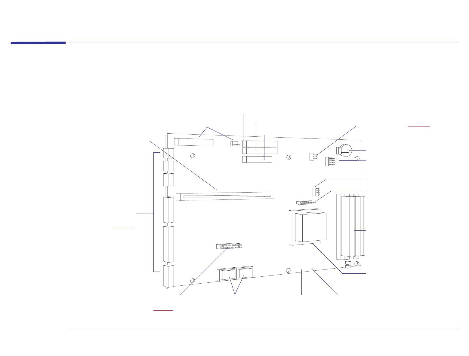
System Board Layout
The following system board block diagram will help you identify where the different components and connections are
located on the board.
Backplane
Connector
Rear Panel
Connectors
(refer to page 79)
Power Connectors
(to power supply)
econdary
Primary IDE Connector
onnector
Clear CMOS (refer to page 20)
Floppy Disk Drive
J1
J30
J12
J15
J20
JP6
1
2
3
JP7
3
5
1
3
5
7
9
J37
21
4
6
Backup Battery
2
4
6
8
10
Processor
Voltage Selection
Clock Ratio
Front Bezel Switch
Connector
Main Memory Module
and Sockets
ABCD
Processor Socket
VESA Feature Connector
(refer to page 93)
Video Memory
Upgrade Sockets
Processor Fan
Connector
Front Bezel Fan
Connector
19
Page 20

1 Introducing the Advanced Setup Guide
System Board Layout
CMOS Jumper (JP6)
The CMOS memory stores information, such as your computer’s configuration, which is preserved when you turn off your
computer. A jumper placed on pins 1-2 prevents changes to the CMOS configuration.
The following table shows the possible pin settings:
Jumper Function Pins Description
Default setting
Clear CMOS
The only time you need to clear the CMOS is if the configuration stored in memory is corrupted or you have forgotten the
system password.
To clear the configuration:
1 Turn off the computer. Unplug the computer from the electrical socket. Disconnect any peripherals from the computer.
2 Remove the computer’s cover (refer to the Upgrade Guide for any assistance).
3 Place the jumper on pins 2-3 (refer to page 19
Note
4 Wait for a couple of seconds, then place the jumper on pins 1-2 to re-enable the configuration.
5 Replace the cover. Reconnect the power cord and any peripherals to the computer.
The CMOS will be cleared only if the computer is unplugged from the electrical socket.
1 - 2
(top two pins)
2 - 3 Place the jumper on these pins to clear the CMOS.
The jumper on these pins prevents any change to the CMOS configuration.
for jumper location on the system board) to clear the CMOS.
6 Turn on the computer.
To set a new system password, you will need to run the Setup program.
20
Page 21

2
Protecting and Using Your PC
This chapter presents an overview of the security features provided with the HP PC and a list of tasks that should be
carried out on a regular basis to protect and look after your files. This section also includes information about the different
features available with the HP Enhanced Keyboard.
Page 22

2 Protecting and Using Your PC
Security Features
Security Features
The HP PC has many security features to protect stored files, and to prevent unauthorized operation of software
applications.
HP Setup Program
The following security features are set by using the HP Setup Program:
• User password.
• Supervisor password (system configuration protection).
• Power-on prompt, with password.
For further information on how to use the program and its features, refer to chapter 3, “
The HP Setup Program”.
Protecting Your PC from Virus Infections
A virus is a small part of a program that is capable of inserting itself in the code of another program, then spreading from
this program to another, and so on. Viruses can have different impacts on your PC, from displaying annoying messages to
damaging data. The regular use of updated antivirus software is the best way to protect your PC against a virus. You
should regularly scan the hard disk and any other disks you use for virus infections.
Your PC is installed with the VirusScan antivirus software. McAfee VirusScan and VShield can be accessed from the HP
data protection center. McAfee VirusScan also includes an on-access scanning component, Vshield, which intercepts and
scans programs before they are executed. However, Vshield will only be activated once you have agreed to the license
agreement that is displayed the first time you use VirusScan.
22
Page 23

2 Protecting and Using Your PC
Maintaining Your Disk and Files
Maintaining Your Disk and Files
To ensure that you have a good and efficient working environment, you can use the tools provided with your HP PC to
protect all your files and keep your system at its highest possible performance level. It is recommended that you schedule
maintenance tasks on your PC on a regular basis.
Improving File Access Time
As programs are continually reading or writing to the hard disk, fragmentation eventually occurs, meaning that files are
stored in non-contiguous sectors. Although this does not have any affect on the files themselves, it does take the
computer a longer time to access fragmented files for reading and writing operations. It is therefore advisable to run a
disk defragmenter on a regular basis, as this consolidates files and thereby improves file access time.
Note
This tool can be accessed from the HP data protection center.
Refer to the Windows 95 documentation for information on how to use the disk defragmenter utility.
It should be noted that when using a defragmenter you can safely use your computer to work on other applications,
but response time will be slower than normal.
23
Page 24

2 Protecting and Using Your PC
Maintaining Your Disk and Files
Increasing Disk Space
If there is a need for some extra space on the disk, this can be met by compressing the files on the disk. Disk drives can
also be compressed. For most programs, a compressed drive appears as a real disk drive.
The Windows 95 utility DriveSpace can compress and manage drives compressed with DriveSpace or DoubleSpace.
To run the Windows 95 DriveSpace utility:
1 Click the Start button.
2 Select Programs, then Accessories, then System Tools.
3 Select DriveSpace, then click the drive you want to compress.
It should also be noted that whenever a file or directory is deleted, it is moved to the Windows 95 Recycle Bin. You should
check this regularly and delete any unwanted files. The Recycle Bin can be configured to delete files either immediately
it receives them or, alternatively, only when you request it to do so.
To configure the Recycle Bin:
1 Place the pointer over the Recycle Bin.
2 Click the right mouse button.
3 In the pop-up menu which is then displayed, select Properties, choose the desired configuration, and click OK to save
and exit.
For further details on disk compression and how to reconfigure the Recycle Bin, refer to the Windows 95 documentation.
24
Page 25

2 Protecting and Using Your PC
Using Power Management in Windows 95
Using Power Management in Windows 95
The HP PC has a power-saving capability that is implemented according to the Environmental Protection Agency (EPA)
Energy Star guidelines. You can use the power management features to reduce the power used by your computer and
display when they are not in use.
There are four levels of power saving that you can configure in the Windows 95 Control Panel—two for the display and
two for the computer. For information concerning the power management features offered by the HP Setup program,
refer to “
The following table is designed to help you understand the power management features available in Windows 95, and
their association with the power management features in the BIOS.
Option Feature Comments
Power Management in the BIOS” on page 39.
Display
Low-power standby mode: reduces the power used by your display by automatically switching it to Standby
mode after a certain period of inactivity. You can use this form of power saving if your display is Energy Starcompliant. Use the Display icon in the Control Panel to configure this mode. To return to full power mode,
move the mouse, or press any key on the keyboard.
Shut off monitor mode: reduces the power used by your display by shutting it off after a certain period of
inactivity. This mode saves more power than Low-power standby mode. You can select Shut off monitor
mode if your display is Energy Star-compliant. Use the Display icon in the Control Panel to configure this
mode. To return to full power mode, move the mouse, or press any key on the keyboard.
This feature is not linked to the
computer and BIOS standby feature.
This feature is not linked to the
computer and BIOS suspend feature.
25
Page 26

2 Protecting and Using Your PC
Using Power Management in Windows 95
Option Feature Comments
Computer
Note
Standby mode, activates automatically after a period of time without any computer activity. In this mode,
the processor runs at a slow speed.This feature is enabled by selecting “Allow Windows to manage power
use on this computer” in the Power Properties dialog box. To return the PC to full speed, move the mouse, or
press any key on the keyboard.
Suspend mode, activates manually by choosing Suspend from the Start menu, or by pressing the Power key
on the keyboard. It reduces power used by the PC by stopping the processor. You will return to full power
mode, when any key is pressed on the keyboard, or the mouse is moved.
On certain models, this feature is not available when your PC is in fax wakeup mode.
If your computer is on a Novell network, the Suspend mode option will disconnect you from the network. Some other
software applications are also incompatible with Suspend mode.
The HP Setup Program defines the
timeout duration.
This feature links with the HP Setup
Program. The HP Setup Program
defines the IRQ that will wake-up the
PC from suspend mode.
26
Page 27

2 Protecting and Using Your PC
Enhanced Keyboard
Enhanced Keyboard
The HP Enhanced Keyboard allows you to access directly various software applications. You can also create your own
shortcuts to your most frequent tasks by configuring some keys. For example, you can access your word processor
application at a touch of a single key.
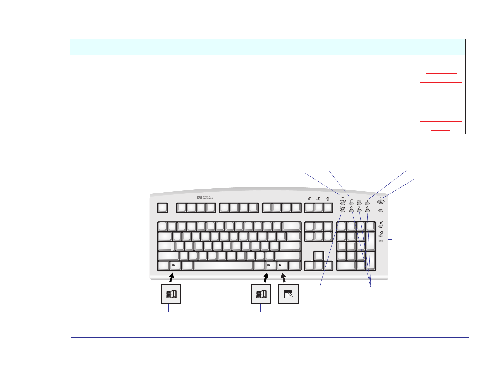
The keys are located on the right-hand side of the keyboard and can be used as follows:
Key Function Configure Key
Messages and LED
HP Centers
Web Browser
Menu
Power
Information
Mute and Volume Control
Monitors the arrival of voice-mail messages, fax messages or electronic mail. The LED blinks when a new voicemail, fax, or E-mail arrives. The LED is turned off when you open the message. Pressing the Message key starts the
Microsoft Exchange program and opens the Inbox folder. If you have not configured Microsoft Exchange, the
configuration dialog box for the Inbox is launched. However, it is recommended that you use the HP
communication center to configure Microsoft Exchange.
Accesses the HP communication, data protection, network, welcome and support centers. No
Launches your default Internet browser configured in your system. No
Displays the current configuration of the keys and the actions mapped to them. No
This key can be used to either turn on power management, lock the keyboard if a password is set in the BIOS, or
start the screen saver.
Starts the HP guide to documentation. No
Press the Mute key to mute the audio. The volume keys are used to adjust the volume level. If no sound card is
installed in your computer, a warning will be displayed on the screen if one of these three keys is pressed.
No
Yes. Refer to
“Configuring
Shortcut Keys” on
page 29
No
27
Page 28
2 Protecting and Using Your PC
Enhanced Keyboard
Key Function Configure Key
You can assign these keys to start applications, open files, or open URLs on the Internet. For example, you can
Shortcuts
(S3, S4, S5)
Phone
1. Available only if you have a communication card installed, and the communication software has been set up through the HP communication center.
access your word processor application at a touch of a single key.
This key can be used to either start the HP phone dialer1 or access telephone directory sites world-wide. If the
hands-free communication application is available, then you can use this key like a hands-free button on a regular
telephone. You can also reconfigure this key in the same way as the shortcut keys.
Messages key, with
mail LED
HP centers WEB browser Menu key
Shortcut Keys” on
Shortcut Keys” on
Power key
Information
Mute
Volume control
Yes. Refer to
“Configuring
page 29
Yes. Refer to
“Configuring
page 29
Display the Windows 95 Start menu by
pressing either of the two Windows keys.
Phone key
Access the right-mousebutton functions.
Shortcut keys
28
Page 29
2 Protecting and Using Your PC
Enhanced Keyboard
Configuring Shortcut Keys
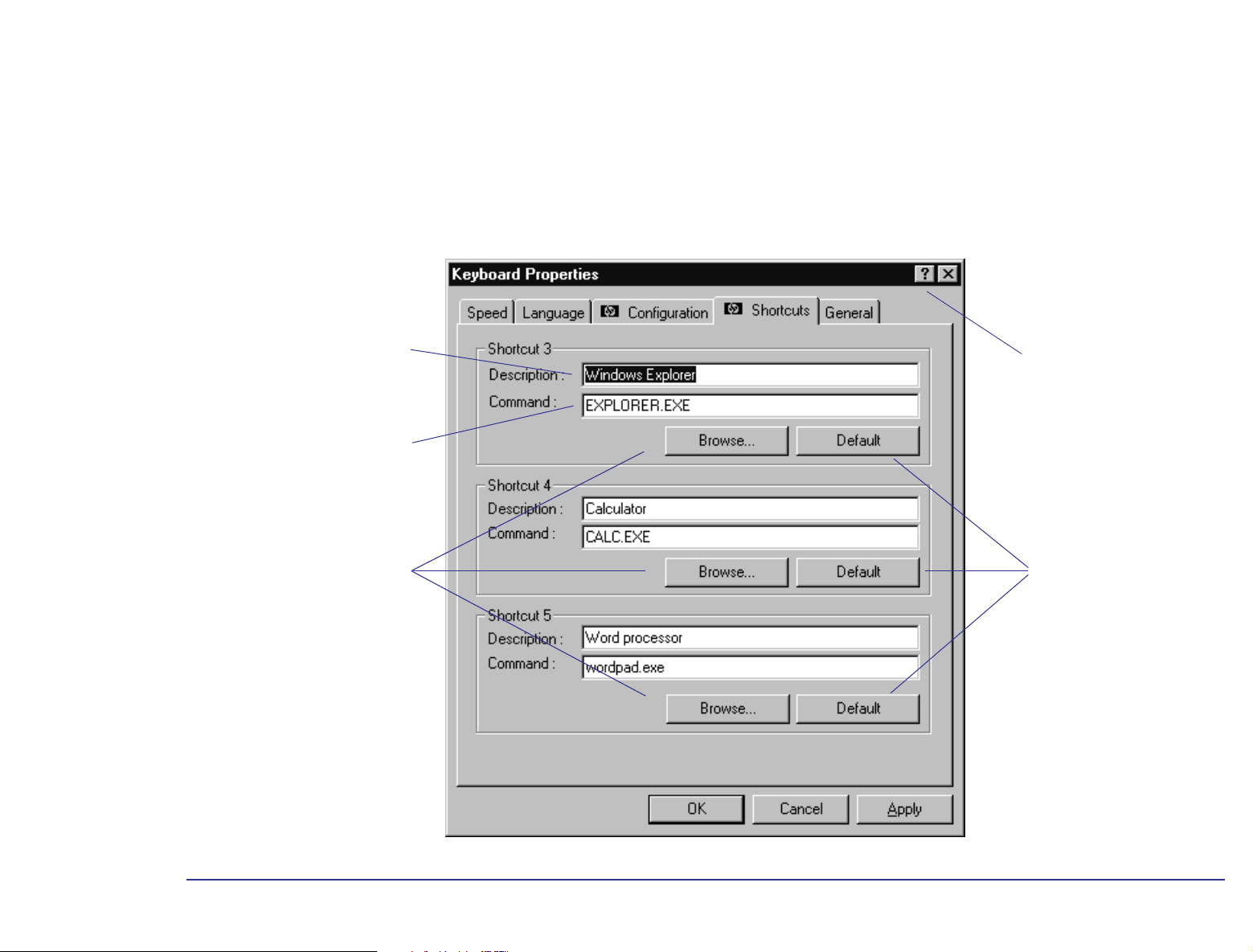
You have three standard configurable shortcut keys (S3, S4, S5), along with the Phone Dialer which can also be
configured. You can configure shortcut keys from the Control Panel. Double-click the Keyboard icon, then select the
Shortcuts tab from the Keyboard Properties screen. To define a Shortcut key, you need to:
Provide a Description of the
application you are assigning to
the Shortcut key.
Provide a Command, which is
the executable that starts the
application.
Click here to activate the
Question Mark pointer. Then
click any element to obtain
information.
Use the Browse button to
locate the file you want to use
in the Command field.
Click here to restore the
HP default settings.
29
Page 30

2 Protecting and Using Your PC
Enhanced Keyboard
You can configure shortcuts from the Control Panel. Double-click the Keyboard icon, then select the Configuration tab
from the Keyboard Properties screen.
Start Phone Dialer.
Link to telephone directories
world-wide.
Specify your own Description
and Command for this key.
Reduce the power used by the
PC by putting it in suspend
mode.
Lock the keyboard when
desired. The password in the
HP Setup program must be set
to use this option (may not be
supported in some models).
Launch the screen saver for
confidentiality.
Click here to activate the
Question Mark pointer. Then
click any element to obtain
information.
Restores the HP default
settings.
30
Page 31

3
The HP Setup Program
The integrated (ROM-based) Setup program displays the configuration of your HP PC and allows you to set certain
parameters.
Page 32

3 The HP Setup Program
HP/Phoenix BIOS Description
HP/Phoenix BIOS Description
The System ROM contains the BIOS1 (System BIOS, video BIOS and low-option ROM) and the power-on self-test
routines that allow you to view the results of the diagnostics and provide you with error corrective-action messages if
necessary.
The System BIOS can be updated by running the PHLASH utility with the latest BIOS firmware. This can be ordered from
HP or downloaded from one of the HP online services.
Power-On Self-Test (POST)
The Power-On Self-Test (POST)is executed each time the system is turned on or a reset is performed. The POST process
checks that system components are operating correctly and initializes certain system parameters.
Beep Codes
If a terminal error occurs during POST, the system issues a beep code before attempting to display the error. Beep codes
are useful for identifying the error when the system is unable to display the error messages.
1. BIOS = Basic Input/Output System
32
Page 33

The following table is a list of beep codes issued for terminal errors.
Beep Pattern Numeric Code Description
B4h This does not indicate an error
There is one short beep before system startup
16h BIOS ROM checksum failure
20h DRAM refresh test failure
22h 8742 Keyboard controller test failure
2Ch RAM failure on address line
2Eh RAM failure on data bits in low byte of memory bus
30h RAM failure on data bits in high byte of memory bus
46h ROM copyright notice check failure
58h Unexpected interrupts test failure
3 The HP Setup Program
HP/Phoenix BIOS Description
98h Video configuration failure or no card installed
Option ROMs checksum failure
33
Page 34

3 The HP Setup Program
HP Setup Program
HP Setup Program
The built-in Setup program is accessed by pressing the key during the Power-On-Self-Test or POST. Online help for
an item on the Setup screen can be obtained by highlighting the item. Help is then displayed on the right of the screen.
It is updated as you move the cursor to each field.
The band along the top of the screen offers the following menus:
• Main. For basic system configuration.
• Advanced. Set the Advanced Features available on the system’s chipset.
• Security. Set the different password levels, and access controls on drives. For information on how to set supervisor
and user passwords, refer to “
• Power. Select power-management modes to reduce the amount of energy used after specified periods of inactivity.
Refer to “
Power Management in the BIOS” on page 39.
Setting Passwords” on page 36.
• Boot. Choose your boot device order and priority. Refer to “Boot Device Priority” on page 36.
• Exit. Leave the Setup program. Refer to “Saving Your Changes and Leaving Setup” on page 40.
To select a menu, move to the appropriate name, using the left and right arrow keys. Then use the plus-and-minus value
keys to select a value for that field. Setup changes system behavior by modifying the power-on initialization parameters.
Setting incorrect values may cause system boot failure. Should this occur, press the key. This will load Setup
default values to recover. HP strongly recommends that you take note of any change to the system setup.
34
Page 35

3 The HP Setup Program
HP Setup Key Functions
The following key functions are available when using the HP Setup program.
• The or arrows can be used to select fields in the current menu.
• The key moves to the top item, and the key moves to the bottom item of the current menu.
• The key displays a sub-menu for menu items marked with a solid right arrow .
• The key or + keys allow you to exit from a sub-menu.
• The and arrows select menus from the menu bar.
• The key loads factory-installed default values.
• The key saves and exits from the Setup program.
• The key or + keys displays the general help screen.
HP Setup Program
• The key exits from the general help screen.
Pressing the or arrows while you are on a main menu screen will take you to the next menu option. If,
however, you are on a sub-menu screen and you press these arrows, you will stay on that screen.
Use the and arrows to scroll through the items on the general help screen.
35
Page 36

3 The HP Setup Program
HP Setup Program
Boot Device Priority
You can select the order of the devices from which the BIOS attempts to boot the operating system. During POST, if the
BIOS is unsuccessful at booting from one device, it will then try the next one on the Boot Device Priority list until an
operating system is found. The default boot device is the floppy disk.
The Boot Device Priority can be changed through the Boot menu. Use the or arrows to move along the top
of the main menu bar to its location. The item is then highlighted and displays the available boot options.
Main PowerAdvanced Security ExitBoot
To select the boot device, use the and arrows, then press the key to move the device up the list, or the
key to move it down the list.
Summary Screen
This is one of the Boot menu options. A summary screen displays a summary of the current configuration and settings of
your PC. This option is disabled by default. You can enable the summary screen option, by accessing the Boot menu (as
explained above), and then use the legend keys to change the value.
Setting Passwords
You can set passwords to provide different levels of protection for your PC. The passwords are set in the Security menu
group of the Setup program, and are disabled by default.
If you have set both a Supervisor Password and a User Password, and you enter the Setup program by using the User
Password, you will be restricted in your ability to change setup items. If you enter the Setup program with a Supervisor
Password, you will have no restrictions.
36
Page 37

3 The HP Setup Program
HP Setup Program
Note
To access the Security menu, use the or keys to move along the top of the main menu bar to its location. The
item is then highlighted and displays the available password and anti-virus options.
It is recommended that you set a password that you can easily remember.
Main PowerAdvanced Security ExitBoot
Supervisor Password
Set the Supervisor Password to protect your computer’s configuration by preventing access to the Setup menus. Full
access to the Setup menus will only be possible by using the Supervisor Password.
To set the Supervisor Password:
1 Start the Setup Program. Refer to “HP Setup Program” on page 34.
2 Select the Security menu group. Then select the “Set Supervisor Password” item.
3 You will be asked to enter your password twice. Be sure to save your changes before you exit the Setup program.
User Password
Setting a User Password gives restricted access to the Setup program. This password can only be set if a Supervisor
Password has already been set.
To set a User Password:
1 Start the Setup Program.
2 Select the Security menu group. Then select the “Set User Password” item.
3 You will be asked to enter your password twice. Be sure to save your changes before you exit the Setup program.
37
Page 38

3 The HP Setup Program
HP Setup Program
Password on Boot
Enabling a password entry on boot can provide a power-on password prompt to prevent your PC being started or used in
your absence. The password is entered when the POST has completed, then the computer finishes its normal startup
procedure. Password on boot can only be enabled if a Supervisor Password has already been set. It should be noted
that this password option is not linked with your Windows operating system.
After three unsuccessful attempts, your computer will be disabled. If this is the case, turn your computer off and
Note
To enable a Password on Boot:
1 Start the Setup Program.
2 Select the Security menu group. Then enable the “Password on boot” item.
3 Be sure to save your changes before you exit the Setup program.
then on again, then enter the correct password. If you have forgotten your password, you need to clear the CMOS
configuration. Refer to page 20
for an explanation on how to clear the CMOS.
38
Page 39

3 The HP Setup Program
HP Setup Program
Power Management in the BIOS
The HP Setup program enables you to reduce the PC’s power consumption when you are not using it. To access the
Power menu, use the or keys to move along the top of the main menu bar to its location. The item is then
highlighted and displays the available power management options.
Main Advanced Security ExitBootPower
Select Customized to set your own power management options. To turn off the power management option, select
Disable.
The following table is designed to help you understand the power management features available in the HP Setup
program, and their association with the power management features in Windows 95.
Mode Description
Standby Timeout Significantly reduces power consumption. In this mode, the display is suspended. The system remains fully
working, but runs slower. Any user event, such as from the mouse or keyboard, will instantly cause the
system to resume. The timeout duration is defined in the HP Setup program.
On certain models, this feature is not available when your PC is in fax wakeup mode.
Suspend Timeout Reduces power consumption to a minimum. Graphics, the processor, and hard disks (IDE and SCSI) are
stopped (placed in their respective off modes). A key press will cause the system to resume to full mode
within a few seconds. The IRQ s that wake up from suspend mode are defined in the HP Setup program.
On certain models, this feature is not available when your PC is in fax wakeup mode.
Fixed Disk Timeout Powers down the fixed disk after a predefined period of inactivity. Any activity accessing the fixed disk will
cause the system to resume.
The above features are supported in Windows 95. For information concerning the power management features offered
by Windows 95, refer to “
documentation for detailed information about how to implement power management.
Using Power Management in Windows 95” on page 25. Refer to your operating system
39
Page 40

3 The HP Setup Program
HP Setup Program
Saving Your Changes and Leaving Setup
When you have made all your changes, you must save them and exit Setup.
1 Press the key to enter the Exit menu.
2 Select Exit Saving Changes to save your changes and exit Setup.
The PC will automatically restart. If you set a User Password, the PC will display the power-on prompt. Enter the User
Password to use the PC.
40
Page 41

4
Business Communications Options
Depending on the HP PC you have purchased, you may have built-in advanced communications and telephony options
installed.
Page 42

4 Business Communications Options
Introduction
Introduction
The communications option provides you with hands-free communication and multimedia functions, through the use of a
headset and audio devices. It also provides communications tools that give you the possibility to send and receive faxes,
receive voice messages, and access Bulletin Board Systems (called BBSs). You can upload and download files and
computer software to and from a BBS.
What you will probably appreciate most in the communications option is its telephone answering capabilities and the
possibility for everyday modem-to-modem exchange of business faxes and files.
Service providers, including America Online, CompuServe, GEnie, and Prodigy, supply access to services such as
electronic mail, airline reservations, banking and finance, and computer support forums.
In addition, certain service suppliers can provide you with access to worldwide networks such as the Internet. You can
use specialized navigation tools like Web browsers to roam through a vast realm of interconnected information systems.
Your communications option is fully compliant with both U.S. and international communications standards. Compatibility
with these standards ensures that you can communicate with other modems anywhere in the world.
What Is a Modem?
A modem allows your computer (the local station) to communicate with another computer (the remote station) through
an analog telephone line. Each system must have its own modem.
42
Page 43

4 Business Communications Options
Introduction
Your communications option
connects your HP PC to:
- telephones
- fax machines
- networks
- other systems with modems
43
Page 44

4 Business Communications Options
How Your Modem Works
How Your Modem Works
In data mode your Modem takes advantage of the typical network configuration found when an analog subscriber
connects to a digitally connected server. Because it bypasses the analog-to-digital conversion in the downstream path,
the modem can use nearly all of the available 64 kbps network bandwidth.
Data sent by the modem (which is typically less speed sensitive) travels at the standard V.34 rate. Your Modem is 56 kbps
capable. However, current regulations limit download speeds to 53 kbps.
Modem Features
As well as combining computer and telephone technologies, your communications option has the following features:
• High speed Internet access at up to 56 kbps.
• High speed data transfer at up to 33,6 kbps.
• High speed fax send and receive rates of up to 14,4 kbps.
• Voice capability (by using a sound card and software enabled for voice modem support).
44
Page 45

4 Business Communications Options
Software Settings
Software Settings
The modem card in your computer supports Plug and Play. This means that, when the card is installed or reinstalled,
Windows 95 is able to automatically configure various software settings to enable the computer to communicate with the
card:
• The IRQ (Interrupt Request) line is the signal line a device uses to notify your computer’s microprocessor that it wants
to send or receive data for processing.
• I/O addresses (or I/O address ranges) enable your computer’s microprocessor to access various peripheral devices
connected to your system when sending or receiving data.
The following table gives the preferred settings of the card. Windows 95 may change these settings when a card is
installed or reinstalled to avoid a conflict between the different accessories on your computer.
Modem Interface:
The operating system may change these settings when a board is installed or reinstalled if another peripheral device uses
the same I/O address or interrupt setting as the modem card (known as a hardware conflict).
I/O Address Range:110H to 117H
Port:COM3
IRQ Line:IRQ 9
45
Page 46

4 Business Communications Options
Software Settings
Viewing the Software Settings
All of the settings are software-configurable. There are no jumpers to set on the card. Plug and Play means you should
never experience a conflict with the settings. To view the modem settings:
1 Click the Start button and select Settings, then Control Panel.
2 Click the Modems then the Diagnostics tab.
3 In the list of Ports, you will see the COM port set for the modem. Select this and click More Info... This window then
displays the modem settings.
Caution
As many applications are designed to work with your default settings, you are advised not to change the settings
unless you are very familiar with PC configuration.
46
Page 47

4 Business Communications Options
Basic AT Commands
Basic AT Commands
This section describes the AT commands supported by your modem. If you send an AT command that is not applicable,
the modem returns an error message. See
The following table lists the basic AT commands.
Command Description
+++ Escape characters used to switch between Data mode and Command mode. In either case the computer stays connected to remote modem.
ATA Manually answers incoming calls. Modem does not answer the telephone.
A/ Repeats the last command line executed.
AT Attention. Begins each command line, except A/. Tests that your modem is working and configured correctly. If characters you type do not
appear on your screen, your modem is not configured properly.
Modem Response Messages, on page 52.
ATBn Switches between BELL/ITU standards at 300 or 1200 bps, where n is either 0 or 1:
0 - The ITU V.22, V.21 (factory default) standard.
1 - The Bell 212A and Bell 103 standard.
47
Page 48

4 Business Communications Options
Basic AT Commands
Command Description
ATDn Tells the modem to go online and dial (automatic dialing). The following characters are authorized as parameters in the dialing sequence:
0 to 9 - For the telephone numbers.
P - For pulse dialing.
T - For touch tone dialing.
W - Tells modem to wait until it hears the line free signal (for use with branch exchanges).
S=n - Dials the number stored in register n (where n is a number from 0 to 3).
! - Calls exchange by flash.
^ - Switches off calling tone (during current dialing process).
;H - Terminates the dialing sequence and causes the modem to go offline after dialing so that you can conduct a normal voice
conversation. Example: ATDT123456;H.
, - Pauses the register (S8) time.
@ - Waits for 5 seconds of silence.
; - Stays in Command Mode after dialing.
ATEn Controls the Echo function, where n is either 0 or 1:
1 - Enables character echo so that modem commands appear on screen as they are entered.
0 - Disables the echo function.
ATHn Where n is either 0 or 1:
0 - Forces modem on-hook.
1 - Forces modem off-hook.
48
Page 49

Command Description
ATIn Returns information about modem product codes, where n is a digit from 0 to 8.
0 - Four-digit product code.
1 - Results of poor checksum.
3 - Product type.
4 - Current modem settings.
5 - Non-volatile memory (NVRAM) settings.
6 - Link diagnostics.
7 - Product configuration.
8 - Return the blacklisted phone numbers.
ATLn Loudspeaker volume control, where n is a digit from 0 to 3:
0 - Modem speaker disabled.
4 Business Communications Options
Basic AT Commands
1 - Low speaker volume.
2 - Medium speaker volume.
3 - High speaker volume.
ATMn Switches speaker on or off, where n is a digit from 0 to 3:
0 - Speaker off.
1 - Speaker on until carrier detected.
2 - Speaker always on.
3 - Speaker on during handshake.
49
Page 50

Command Description
ATOn Returns online, where n is either 0 or 1:
0 - Returns online.
1 - Returns online and retains.
ATQn Control modem responses, where n is either 0 or 1:
0 - Enables response messages (default).
1 - Disables response messages.
ATSr? Reads the value of the S register r. Example: ATS0?
ATSr=n Changes the value of S register r to value n. Example: ATS0=1
S0 = auto-answers calls on the ring corresponding to this register value:
ATS0=1 - auto-answers calls on first ring.
ATS0=0 - turns off auto-answer; to manually answer calls, use the A command.
4 Business Communications Options
Basic AT Commands
ATVn Selects modem message format (alphabetic or alphanumeric), where n is either 0 or 1:
0 - Sends responses as numbers.
1 - Sends responses as characters.
ATXn Sets result code displayed. Default value is X4.
ATYn Selects power on/reset default configuration, where n is either 0 or 1:
0 - Default is profile 0 setting in NVRAM.
1 - Default is profile 1 setting in NVRAM.
ATZn Resets modem and uses one of two stored profiles. The n parameter (0 or 1) is used to reset the modem to the preferred profile. Any
commands following the ATZn command are ignored.
AT\N5 Makes MNP links only.
50
Page 51

4 Business Communications Options
Basic AT Commands
Command Description
AT&Cn Selects data compression for MNP or V.42, where n is a digit from 0 to 3. For data compression to work, both the local and the remote
modem must have compression capabilities. The n parameters are:
0 - Compression is not authorized.
1 - Auto enable/disable.
2 - Data compression enabled.
3 - MNP5 compression disabled.
AT&Dn This command controls the way that your modem responds to the Data Terminal Ready (DTR) signal:
0 - Ignores DTR signal.
1- Modem interprets an ON-to-OFF transition as escape characters and moves to Command Mode, while keeping data connection.
2 - An ON-to-OFF DTR transition causes the modem to hang up and disables auto-answer.
3 - An ON-to-OFF DTR transition resets the modem to hang up and disables auto-answer.
AT&F Modem returns to factory default settings.
AT&Kn This command controls the flow control:
0 - Disables flow control.
1 - Enables RTS/CTS (hardware) flow control (default).
2 - Enables XON/XOFF (software) flow control.
51
Page 52

4 Business Communications Options
Modem Response Messages
Modem Response Messages
In response to AT modem commands, the modem returns status information in the form of response messages. These
messages appear on the screen when you enter a modem command and press Enter. You can instruct the modem to
return responses in English language words (with the
The most common responses are described in the table below (the numeric equivalents are in parentheses).
Message Description
(00) OK The command was carried out successfully.
(01) CONNECT For X0: the modem has made a data connection.
(02) RING Modem is receiving incoming call.
V1 command) or as numeric values (with the V0 command).
(03) NO CARRIER The remote carrier signal is not detected.
(04) ERROR You typed an invalid command line or a command line that is too long.
(05) CONNECT 1200 Modem is configured to report line speed, which is 1200 bps; or modem is configured to report the DTE speed, which is 1200 bps.
(06) NO DIAL TONE The modem cannot dial the number you specified because there is no dial tone (this response is enabled when the X2, X4, or W
modifier is in effect).
(07) BUSY Modem has not detected a busy signal (this response is enabled when X3 or X4 are in effect).
(08) NO ANSWER Modem did not detect silence when dialing a command line containing the @ modifier within the time specified by register S7.
(09) CONNECT 0600 Modem is configured to report line speed, which is 600 bps; or modem is configured to report the DTE speed, which is 600 bps
(this response is disabled when X0 is in effect).
(10) CONNECT 2400 Modem is configured to report line speed, which is 2400 bps; or modem is configured to report the DTE speed, which is 2400 bps
(this response is disabled when X0 is in effect).
52
Page 53

Message Description
4 Business Communications Options
Modem Response Messages
(11) CONNECT 4800 Modem is configured to report the DTE speed, which is 4800 bps.
(12) CONNECT 9600 Modem is configured to report the DTE speed, which is 9600 bps.
(13) CONNECT 7200 Modem is configured to report the DTE speed, which is 7200 bps.
(14) CONNECT 12,000 Modem is configured to report the DTE speed, which is 12,000 bps.
(15) CONNECT 14,400 Modem is configured to report the DTE speed, which is 14,400 bps.
(16) CONNECT 19,200 Modem is configured to report the DTE speed, which is 19,200 bps.
(17) CONNECT 38,400 Modem is configured to report the DTE speed, which is 38,400 bps.
(18) CONNECT 57,600 Modem is configured to report the DTE speed, which is 57,600 bps.
(19) CONNECT 115,200 Modem is configured to report the DTE speed, which is 115,200 bps.
(22) CONNECT
Carrier transmit 75 bps, receive 1200 bps.
1
1
1
1
1
1
1
1
1
1
75TX/1200RX
(23) CONNECT
Carrier transmit 1200 bps, receive 75 bps.
1
1200TX/75RX
(24) DELAYED For X4, a call fails to connect and the number dialed is considered “delayed” due to country blacklisting requirements.
(32) BLACKLISTED Modem has dialled a telephone number that has been blacklisted, and has failed to make a connection.
(33) FAX Fax/modem connection established in fax mode.
(35) DATA Data modem connection established in fax mode.
(40) CARRIER 300 V.21 or Bell 103 carrier detected at 300 bps.
(44) CARRIER 1200/75 Carrier—transmit at 1200 bps, receive at 75 bps.
(45) CARRIER 75/1200 V.22 or Bell 212 carrier detected at 1200 bps.
2
2
2
53
Page 54

Message Description
4 Business Communications Options
Modem Response Messages
(46) CARRIER 1200 V.22 or Bell 212 carrier detected at 1200 bps.
(47) CARRIER 2400 V.22bis carrier detected at 2400 bps.
2
(48) CARRIER 4800 V.32bis or V.32 carrier detected at 4800 bps.
(49) CARRIER 7200 V.32bis carrier detected at 7200 bps.
2
(50) CARRIER 9600 V.32bis or V.32 carrier detected at 9600 bps.
(51) CARRIER 12,000 V.32bis carrier detected at 12,000 bps.
(52) CARRIER 14,400 V.32bis carrier detected at 14,400 bps.
(53) CARRIER 16,800 V.34 carrier detected at 16,800 bps.
(54) CARRIER 19,200 V.34 carrier detected at 19,200 bps.
(55) CARRIER 21,600 V.34 carrier detected at 21,600 bps.
(56) CARRIER 24,000 V.34 carrier detected at 24,000 bps.
(57) CARRIER 26,400 V.34 carrier detected at 26,400 bps.
(58) CARRIER 28,800 V.34 carrier detected at 28,800 bps.
(78) CARRIER 31,200 V.34bis carrier detected at 31,200 bps.
2
2
2
2
2
2
2
2
2
2
2
2
(79) CARRIER 33,600 V.34bis carrier detected at 33,600 bps.
2
(59) CONNECT 16,800 Modem is configured to report the DTE speed, which is 16,800 bps.
(61) CONNECT 21,600 Modem is configured to report the DTE speed, which is 21,600 bps.
(62) CONNECT 24,000 Modem is configured to report the DTE speed, which is 24,000 bps.
(63) CONNECT 26,400 Modem is configured to report the DTE speed, which is 26,400 bps.
(64) CONNECT 28,800 Modem is configured to report the DTE speed, which is 28,800 bps.
2
2
2
2
2
54
Page 55

Message Description
4 Business Communications Options
Modem Response Messages
(84) CONNECT 33,600 Modem is configured to report the DTE speed, which is 33,600 bps.
(91) CONNECT 31,200 Modem is configured to report the DTE speed, which is 31,200 bps.
(66) COMPRESSION CLASS 5 MNP 5 compression negotiated.
(67) COMPRESSION
V.42bis compression negotiated.
2
2
2
2
V.42bis
(69) COMPRESSION NONE No compression negotiated.
2
(70) PROTOCOL NONE Protocol reporting enabled using X4 and Register S95, and modem has made a data connection without any error correction.
(77) PROTOCOL LAPM Modem has made a data connection using V.42 LAPM error correction.
(80) PROTOCOL: ALT Modem has made an MNP connection.
(81) PROTOCOL: ALT-
Modem has made an MNP 10 connection.
2
2
2
CELLULAR
1. Response is enabled by the \V1 command and ignored when the W1 command is in effect.
2. These negotiation-progress responses are sent when the W1 command is in effect.
2
55
Page 56

4 Business Communications Options
Modem Response Messages
56
Page 57

5
Using Sound on Your PC
Depending on the HP PC you have purchased, you may have a sound card installed. This section helps you to set up your
sound programs and to solve any problems that you may encounter.
Page 58

5 Using Sound on Your PC
Why Do I Need Sound?
Why Do I Need Sound?
Sound is an essential element in multimedia computing. But just what is “multimedia computing”, and what can you do
with it? With the multimedia sound option in your PC, you can:
❒Run training applications that use speech and music.
❒Use presentation software to create and run promotional or information displays.
❒Run multimedia applications, such as games and encyclopedias, that use sound either on your computer or from the
Internet.
58
Page 59

5 Using Sound on Your PC
Why Do I Need Sound?
Furthermore, using the standard audio software on your computer, you can:
❒Record speech or music (as “wave files”) and embed these sounds in other programs. This is useful for creating training
programs.
❒Play music CDs or MIDI files on your computer (MIDI files are a way of storing music, especially music created by
keyboard instruments).
❒Record, play, and edit pieces of music or sound (stored as wave files).
.
59
Page 60

5 Using Sound on Your PC
Running the Audio Programs
Running the Audio Programs
Your HP PC has full audio capability. The sound card’s features can be used by any other application that supports
standard PC audio capability.
For example, you can add computer software for creating your own multimedia business presentations and training
programs, building in voice-over, graphics, and audio enhancements.
Your computer includes several audio software tools to enable you to have complete control of the audio input to these
applications:
1 Click the Start button on the taskbar.
2 Select Programs, then Accessories, then Multimedia.
A selection of audio programs appears:
CD Player For playing music CDs. This program gives you the normal hi-fi display to show number of tracks, elapsed playing time, and
so on.
Media Player To play either MIDI files, music CDs or sound files. The MIDI player makes use of the sound card’s built-in synthesizer.
Sound Recorder To record sounds from various sources as wave files.
Volume Control To control the input and output volumes of the other players and sound recorder.
Note
Warning
The output volume may initially be set to zero in the audio software. If you don’t hear any sound, adjust the volume
using the audio software.
If using a headphone for testing your sound card, do not connect the headphone to the SPK output. Refer to
“Connecting Audio Devices to the Rear Panel” on page 82 for further details.
60
Page 61

5 Using Sound on Your PC
Testing Your Audio Setup
Testing Your Audio Setup
There are many sample wave and MIDI files on your computer which you can play to check that your audio system works.
Before testing your audio setup, set Mixer bars to mid range.
Warning
1 Click the Start button on the taskbar.
2 Select Programs, then Accessories, then Multimedia, then Media Player.
3 Open the Device menu in Media Player and select either Sound to play a wave file or MIDI Sequencer to play a MIDI file.
4 In the Open window, locate and select a file, then click the Open button.
You can find the files used by the Windows 95 operating system in C:\Windows\Media.
5 To play the file, click the Play button
6 To adjust the volume, click the speaker symbol in the right corner of the taskbar (or select Volume Control from
the Media Player’s Device menu) and adjust the volume level. Or double-click the speaker symbol to display separate
mixer controls.
If you don’t hear any sound, even after adjusting the volume level, refer to the online help troubleshooting information
for advice.
Before testing your audio setup for the first time, make sure the volume control is set well below maximum to avoid
injury from excessive noise. Click the speaker symbol in the right corner of the taskbar and move the slider
down to about a third of full volume.
61
Page 62
5 Using Sound on Your PC
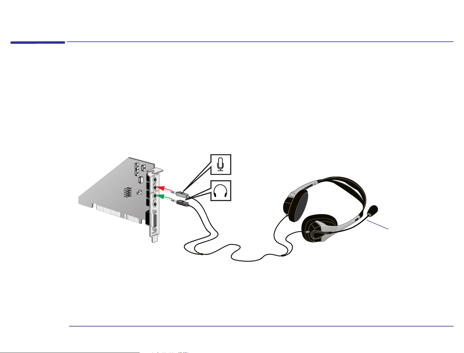
How to Use a Headset
How to Use a Headset
For recording and listening to messages, a headset must be used, and is connected directly to the sound card.
On the headset there are normally two connectors that have to be connected to the sound card: one for the microphone
and the other for the speaker.
The following illustration shows how to connect a headset to the sound card. (Note: Your headset might be different to
the one shown).
Adjust the
microphone
arm position
to obtain the
best sound
quality.
62
Page 63

5 Using Sound on Your PC
How to Use a Headset
When the telephone line and headset are connected, you are ready to use the communications software. The software
can be accessed from the HP communication center. For further information concerning the communications software,
refer to the documentation Communications.
Warning
To avoid discomfort from unexpected noise or static, always turn down the volume before connecting the
headphones or speakers to your computer. Whenever you wish to use the headphones, first place them around your
neck and check that the volume is turned down. Then, put on the headphones and slowly increase the volume by
using the Audio Mixer Applet or the enhanced keyboard until you find a comfortable listening level, where the sound
is clear, without being too loud. Listening to loud sounds for prolonged periods of time may permanently damage your
hearing.
Volume Control
The volume for the headset can be controlled either by using the communications software (audio mixer and telephony
applications) or by using the enhanced keyboard. Whichever method you use, the volume adjustment is automatically
made to the other.
Communications Software
To obtain the best audio quality for yourself and the caller, it is recommended that you configure the audio mixer and
telephony applications.
If you are listening to a CD-ROM when you receive a telephone call, another feature automatically puts your CD-ROM on
Mute while you have your conversation. When finished, the CD-ROM volume automatically returns to its initial setting.
63
Page 64

5 Using Sound on Your PC
How to Use a Headset
To configure the audio mixer and telephony applications, you must do the following:
Telephony application. Check that the volume control button is set to approximately one-third of the maximum
amplitude. To check or modify the volume control, double-click the Cheyenne icon in your task bar. The following dialog
box opens.
Note
Volume control set at
one-third of the
maximum amplitude
The volume control has no effect on the microphone input
64
Page 65

5 Using Sound on Your PC
How to Use a Headset
Audio mixer. Check that the microphone input is disabled, and that the speaker output and line-in input are set
between one-third and half the maximum amplitude.
To check or modify any settings, double-click the speaker symbol in the right corner of the taskbar. This displays the
Volume Control program. Select Properties from the Options menu. In the Properties dialog box, make sure the following
steps are carried out.
Check that
Playback is
selected
Select Volume
Control
Select Line-In
Select Microphone
Click OK to return
to Volume Control
The above illustration is for example purposes only.
65
Page 66

5 Using Sound on Your PC
How to Use a Headset
With the Volume Control dialog box displayed, adjust the volume control levels so that they are similar to those shown
below. Select Mute to remove the local echo when using the telephone.
Left/right
balance
controls
Volume level
Mute checkbox
selected, to remove
local echo
66
Page 67

5 Using Sound on Your PC
How to Use a Headset
Enhanced Keyboard - Volume Control
There are three keys on the enhanced keyboard that can be used to modify the volume. The following illustration shows
their position on the keyboard.
Press the Mute
key to turn off
the sound
Press to turn
volume up
Press to turn
volume down
For detailed information about the HP Enhanced Keyboard, refer to
“Enhanced Keyboard” on page 27.
67
Page 68

5 Using Sound on Your PC
Connecting a MIDI Keyboard
Connecting a MIDI Keyboard
By connecting a keyboard instrument to your computer, and running a sequencer program on your computer to control
your musical arrangements, you can create a mini-recording studio. The keyboard instrument you use must have MIDI
capability, as most modern instruments do.
Keyboard
Synthesizer
MIDI OUT
MIDI IN
Sequencer
program
Speakers
Rear
Panel
68
Page 69

5 Using Sound on Your PC
Connecting a MIDI Keyboard
You store your arrangements in a MIDI file, which is like an orchestral score—it can contain the sequence of notes for
many different instruments, indicating the pitch and duration of each note and the sort of instrument it should sound
like.
Track Name Loop Key Time Port Channel Patch Volume Size
1 Lead
piano
2 Harmony 1 0 0 1:SB16 2 Clarinet ... 295
3 Bass 2 15 2:External 3 Bass ... 175
4 Trombone 2 15 1:SB16 4 Trombone 85 260
5 Jug 2 15 1:SB16 5 Bottle blow ... 303
1 0 0 2:External 1 Electric Piano ... 301
Each instrument is
played back on its
own channel. You
can play back some
channels through
your computer and
some through your
keyboard instrument.
Setting Up
Your keyboard, Windows 95 settings, and sequencer program must all be set up correctly for you to record and play back
music satisfactorily.
It’s difficult to give precise instructions here for setting up, as the steps depend on your keyboard and on the music
software you are running. For more specific instructions, refer to the documentation that came with your keyboard and
software. However, here are some general guidelines that should help you get started and solve certain problems later.
1 Connect your keyboard instrument to the rear panel of your PC via a MIDI cable, as shown on page 68
.
69
Page 70

2 Direct your computer’s MIDI output to a playback device as follows:
a Click the Windows 95 Start button.
b Select Settings, then Control Panel.
c Double-click the Multimedia icon .
d In the Multimedia Properties dialog box, click the MIDI tab.
• To play back all the channels through the same synthesizer, select Single instrument. Then select either Internal
OPL2/OPL3 FM Synthesis (to play back through the computer’s sound synthesizer) or HP MPU-401 Device (to
play back through your keyboard instrument). If you have several MIDI instruments, select the particular
instrument for playback. (You can first set up each instrument with a distinct name by clicking the Add New
Instrument button and following the wizard’s instructions.)
• To divide the channels between synthesizers, select Custom configuration and then click Configure. Then, select
each channel in turn, click Change, and select a synthesizer for that channel. By clicking Save As, you can save
your configuration with a particular name.
5 Using Sound on Your PC
Connecting a MIDI Keyboard
This configuration feature is often called a MIDI mapper, because it maps the MIDI channels onto the
synthesizers.
e Click OK to save your changes.
Note
3 In your sequencer program, select all the potential MIDI devices you may use for recording (input port) and playback
(output port). Depending on your program, these may be selectable through a Settings menu.
For example, select both the internal synthesizer and the MIDI output port if you intend to divide the channels
between the two playback devices.
The settings in your sequencer program (step 3) may override the settings in Windows 95 (step 2).
70
Page 71

5 Using Sound on Your PC
Connecting a MIDI Keyboard
4 In your sequencer program, for each track select an output port, a channel number, and a patch number or name:
• The output port defines where the track is to be sent for playback: to the computer’s internal synthesizer or to your
keyboard instrument. Bear in mind how many different instrument voices your keyboard is capable of playing back
at the same time.
• The channel number lets you “tune in” a particular keyboard or module to this track. Do not select the same channel
number for two different tracks unless they use the same patch (voice).
• The patch is the instrument voice. Your sequencer program may let you select a MIDI patch number or an instrument
name.
5 On your keyboard instrument, select a channel number or numbers on which to receive MIDI information. The channel
number(s) will depend on which track(s) you want to play back through your keyboard, as set up in your sequencer
program. If in doubt, select channels 1, 2, 3, and so on. You can usually change the channel number(s) as you play back
a piece of music.
71
Page 72

5 Using Sound on Your PC
Software Settings
Software Settings
The sound card in your HP PC supports Plug and Play. This means that, when the card is installed or reinstalled,
Windows 95 is able to automatically configure various software settings to enable the computer to communicate with the
card:
• The IRQ (Interrupt Request) line is the signal line a device uses to notify your computer’s central processor that it
wants to send or receive data for processing.
• The DMA (Direct Memory Access) channel is the signal line a device uses to transfer data directly to the computer’s
memory.
• I/O addresses (or I/O address ranges) enable your computer’s microprocessor to access various peripheral devices
connected to your system when sending or receiving data. There are several such devices on your sound card.
The following table gives the preferred sound settings of the card. Windows 95 may change these settings when a card is
installed or reinstalled to avoid a conflict between the different accessories on your computer.
Audio Interface:
MPU-401 UART MIDI Interface:
(Disabled by default)
Joystick Interface:
Stereo Music Synthesizer
I/O Address Range:220H to 22FH
Joystick Connector:Enabled
IRQ Line:IRQ 5
Low DMA Channel:1
High DMA Channel:3
I/O Address Range:300H to 301H
IRQ Line:IRQ 9
I/O Address Range:200H to 207H
I/O Address Range:388H to 38BH
72
Page 73

5 Using Sound on Your PC
Software Settings
The operating system may change these settings when a card is installed or reinstalled in the following cases:
• Another peripheral device is using the same I/O addresses, DMA channel, or interrupt setting as the sound card (known
as a hardware conflict).
• Another joystick/game connector is already in use in your system.
Viewing the Software Settings
All of the audio settings are software-configurable. There are no jumpers to set on the card. Plug and Play means you
should never experience a conflict with the settings. You can view settings through the Device Manager, as follows:
1 Click the Start button and select Settings, then Control Panel.
2 Open System and click the Device Manager tab.
3 In the list of devices, expand the line Sound, video and game controllers. You will see the audio driver HP Audio Device.
Select this and click Properties.
4 Click the Resources tab. Now you can view the settings. You may need to scroll the list to see all of the settings.
Caution
5 To change a setting, first clear the checkbox Use Automatic Settings. Then select the resource type and click Change
Settings.
6 Select a new setting using the scroll buttons and click OK.
7 Click OK again at the Properties window, and then click Yes at the confirmation message (but please read the message
first!).
8 Click Close at the System Properties window. If you changed any settings, restart your PC for the changes to take effect.
As many applications are designed to work with your default audio settings, you are advised not to change the
settings unless you are very familiar with PC configuration.
73
Page 74

5 Using Sound on Your PC
Playing CDs
Playing CDs
The CD Player program acts in the same way as the CD unit in a hi-fi system. It lets you play music CDs, so you can listen
to music while working. In addition, if you’re creating an audio-visual presentation, you can add CD music or sounds to
your presentation.
1 Click the Start button on the taskbar.
2 Select Programs, then Accessories, then Multimedia, then CD Player.
Insert an audio CD in the CDROM drive, and then click here
to play it.
To stop playing the CD, click this
button.
To eject your CD from the drive,
click here.
These buttons let you skip
tracks or fast forward/rewind,
like on a hi-fi unit.
You can also select a random order of playing tracks, or continuous play (the CD plays again and again). Look in the
Options menu for these features. You can also compile a playlist of tracks for a CD. This means you can specify which
tracks on a CD to play, and in which order, so that the CD Player skips the tracks you don’t want to hear. Find this option
in the Disc menu.
Note
Make sure your headset is plugged into the CD disk drive before listening to a CD.
74
Page 75

5 Using Sound on Your PC
Recording Your Voice
Recording Your Voice
By creating your own sound recordings, you can customize your computer sounds, embed speech in documents, or
create a sound track for a presentation. The programs you use (for example, to create a presentation) will give you
detailed instructions on how to use the recordings. You can record a portion of speech as follows:
1 Click the Start button on the taskbar.
2 Select Programs, then Accessories, then Multimedia, then Sound Recorder.
You can apply some simple
effects—reverse and echo—to
your wave file.
You can record through your
microphone from a MIDI file (play
using Media Player), or from
Use the playback buttons and the slider to
play any part of the file.
another source such as a CD (use
CD Player).
3 To begin recording through the microphone in your headset, click the record button . To finish recording, click the
stop button .
4 To adjust the recording level, double-click the speaker symbol in the taskbar. This displays the Volume Control
program. Now, in Volume Control, select Properties from the Options menu, then click Recording instead of Playback.
Adjust the recording level by moving the slider labeled Microphone.
5 To save the file, select Save from the Sound Recorder’s File menu and enter a file location and name. Save the file as a
wave file (*.wav).
75
Page 76

5 Using Sound on Your PC
Recording Your Voice
Mixing Sounds
The Volume Control program is like a mixing console in a recording studio. It lets you combine sounds from various
sources, adjusting the level of each source independently.
For example, to create a backing track for an audio-visual presentation, you can play music from an audio CD while
recording your own voice through the microphone. You can also adjust the sound levels in Volume Control before
recording the combined sound in Sound Recorder.
To set recording levels, select Properties from the Options
menu, then click Recording instead of Playback. You can
also choose which devices to display.
Left/right
balance controls
Volume levels
Turn off a device
76
Page 77

6
Peripheral Connections
This chapter describes the possible peripheral connections on the minitower backplane, sound card and rear panel for
parallel and serial connections.
Page 78

6 Peripheral Connections
Backplane
Backplane
The minitower backplane supports two 16-bit ISA (Industry Standard Architecture) cards and two 32-bit PCI
(Peripheral Component Interconnect) cards, and has one combination slot for an ISA or PCI card. The five expansion
card slots are arranged as follows:
• Slot 1 (the innermost) - can be used for a short 16-bit ISA card.
• Slot 2 - can be used for a short 16-bit ISA card.
• Slot 3 - Combination slot that can be used for a full-length 16-bit ISA card or a 32-bit PCI card.
• Slot 4 - can be used for a 32-bit PCI card.
• Slot 5 - can be used for a 32-bit PCI card.
Depending on the computer you have purchased, one of the ISA slots could have a sound card already preinstalled.
78
Page 79

6 Peripheral Connections
Connecting the Mouse, Keyboard, Printer and Display
Connecting the Mouse, Keyboard, Printer and Display
Connect the mouse, keyboard and display to the back of the computer, as shown in the following illustration. The
connectors are shaped to go in one way only.
Connect the printer cable to the appropriate connector and tighten the attachment screws. Use the connector labeled:
• Parallel (25-pin parallel connector) for a parallel device.
• Serial A (9-pin serial connector) for a serial device.
Keyboard Connector
Mouse Connector
USB Connector (see note below)
Note
Serial Connector
Parallel Connector
Display Connector
The Universal Serial Bus (USB) connector is between the mouse connector and the serial connector and can be used
for USB accessories. Most USB accessories are automatically configured as soon as they are physically attached to
the PC. USB is not supported by all operating systems.
79
Page 80

6 Peripheral Connections
Sound Card Connectors
Sound Card Connectors
The computer’s sound card has several connectors that allow you to internally connect the card to other devices. This
figure shows where the connectors are located on the sound card.
AUX In Connector
(refer to page 81)
Multimedia
Control Panel
Connector
Internal Speaker
Connector
Telephone Answering
Device Connector
(refer to page 82)
CD Audio
Connector
(refer to page 81)
Multimedia
Control Panel
Microphone
Connector
Jumper blocks are required between pins
3 and 4 and between pins 5 and 6 of the
Multimedia Control Panel Connector.
Without these jumpers, the sound card
will not output sound through the rear
panel. (These jumper connections are
supplied as standard).
Note
The internal connectors Internal Speaker Connector, Multimedia Control Panel Connector and Multimedia Control
Panel Microphone Connector are not used on this computer.
80
Page 81

6 Peripheral Connections
Sound Card Connectors
AUX In Connector
This Auxiliary Connector allows you to connect an additional internal audio source such as a TV tuner, or another similar
card. It can also be used to accept decompressed audio data from an MPEG video card.
The AUX In connector has the following pin assignments:
Pin Signal I/O
1 Analog Ground 2 AUX right channel IN
3 Analog Ground 4 AUX left channel IN
CD Audio Connector
The CD Audio Connector, labeled “CDAUDIO”, allows you to connect the sound card to the CD-ROM drive via the audio
cable, so that you can listen to audio from the CD-ROM drive.
The CD Audio Connector has the following pin assignments:
Pin Signal I/O
1 Analog Ground 2 CD right channel IN
3 Analog Ground -
4 CD left channel IN
81
Page 82

6 Peripheral Connections
Sound Card Connectors
Telephone Answering Device Connector
This connector, labeled “TAD”, is used to connect the sound card to a modem card. You can then conduct a
hands-free phone conversation using a headset.
The TAD Connector has the following pin assignments:
Pin Signal I/O
1 Line out OUT
2 Analog Ground -
3 Analog Ground 4 Mic Input IN
Connecting Audio Devices to the Rear Panel
You can connect external speakers, a microphone, or other audio devices to the rear panel.
Do not connect headphones to the socket on the CD-ROM drive, as this lets you hear output only from music CDs.
Through the rear panel socket on your computer you will hear sounds from training presentations, MIDI music files, any
other audio software, and music CDs too.
Warning
Before connecting the headphones or speakers, always turn the volume down to avoid discomfort from unexpected
noise or static. Listening to loud sounds for prolonged periods of time may permanently damage your hearing. Before
putting on the headphones, place them around your neck and turn the volume down. Then, put on the headphones and
slowly increase the volume by using the Audio Mixer Applet or the enhanced keyboard until you find a comfortable
listening level, where the sound is clear, without being too loud. When you can hear comfortably and clearly, without
distortion, leave the volume control in that position.
82
Page 83

6 Peripheral Connections
Sound Card Connectors
Details of what each socket on the sound card is for are given below.
LINE IN Connect devices such as a cassette, DAT, or Minidisc player for playback and recording.
MIC Connect a microphone for voice input.
LINE OUT Bypass the sound card’s internal amplifier to connect powered speakers, an external amplifier for audio
output, or a recording device (tape deck) or stereo headphones.
SPK Connect speakers for audio output from the card’s built-in power amplifier. Adjust the volume from within
the software or from the multimedia control panel if this feature is on your computer.
Warning
The SPK socket is for a highly amplified output and is therefore not suitable for connecting headphones.
• You can use the LINE OUT socket for headphones with limited power output.
• You can use the LINE OUT socket with amplified speakers which have a dedicated headphone socket for this
purpose.
MIDI/GAME Connect a joystick (for game software) or MIDI instrument. The MIDI port is disabled by default. You will
have to enable this port if you wish to use it with a MIDI.
There are also several internal connectors located on the sound card itself. Information on these is given on page 80.
83
Page 84

6 Peripheral Connections
Modem Card Connectors
Modem Card Connectors
This section describes how to connect the telephone to the modem card depending on whether it is to meet U.S. and
Canada telephone standards, or International telephone standards. Since the modem card in your computer supports
Plug and Play, the hardware settings should not conflict with those of any devices on your system.
Telephone Connections for the U.S. and Canada
The following section only concerns telephone connections for the U.S. and Canada. The modem card has two external
connections that allow you to connect the telephone line and handset. The telephone remains operational even when the
computer is turned off. Connecting these devices enables the use of the modem and telephone:
Plug one end of the cable into the TELCO jack on the modem card. Plug the other end of the cable into a wall jack
for an analog line. If you want to use a telephone on that line when you’re not using the modem, plug the telephone
cable into the modem’s PHONE jack.
Sound card
connector
Telephone connection
TELCO
connection
84
Page 85

6 Peripheral Connections
Modem Card Connectors
International Telephone Connections
The HP PC modem card has been preconfigured to adapt to each country’s particular telephone standards.
The telephone line cable, which is specific to each country, is connected to the RJ-11 socket on the connections card.
This connection enables the use of the modem and telephone. The telephone remains operational even when the
computer is turned off.
Plug one end of the cable into the LINE jack on the modem card.
Plug the other end of the cable into a wall jack.
Plug the telephone cable into the socket on the end of the telephone line cable.
Sound card
connector
LINE
connection
85
Page 86

6 Peripheral Connections
Modem Card Connectors
Warnings
Safety Information
Do not attempt to connect this product to the telephone line during a lightning storm.
Never install telephone jacks in wet locations unless the telephone line has been disconnected at the network
interface.
Never touch uninsulated telephone wires or terminals unless the telephone line has been disconnected at the
network interface.
Use caution when installing or modifying telephone lines.
Avoid using a telephone (other than a cordless type) during a lightning storm. There may be a risk from lightning.
Do not use the telephone to report a gas leak in the vicinity of the leak.
Always disconnect the host computer from any analog telephone circuits before removing any covers.
Never touch or remove the communications card without first removing the connection to the telephone
network.
Analog Telephone Line
To use this modem, you must have an analog telephone line. If you are not sure if you have an analog telephone
line or a digital line, have it verified by the person in charge of your telephone system before you install your
modem.
Caution
The modem will be damaged if you use a digital telephone line.
86
Page 87

7
Technical Characteristics
This chapter provides the default configuration settings of your HP PC. If you intend to upgrade the current
configuration, refer to the following tables to check what can be upgraded.
Page 88

System Characteristics
Feature Default Configuration
BIOS 2 MB Flash BIOS
Level-one cache 8 KB code, 8KB write-back data
Level-two cache 256 KB synchronous pipeline burst cache
7 Technical Characteristics
System Characteristics
Main memory
(size/speed)
Disk drive controller Master Enhanced IDE controller on PCI bus
Rear panel
connectors
Modules 4, 8, and 16 MB.
• mini-DIN mouse
• mini-DIN keyboard
• 25-pin parallel
• 9-pin serial (buffered)
• USB connector
• 15-pin VGA
25-pin parallel
connector
9-pin serial
connectors
System board
connectors
• Mode: Centronics©, bidirectional, EPP, or ECP.
• Standard: One UART 16550 buffered serial port (RS-232-C)
• VESA internal video pass-through connector
• One floppy disk drive cable with two drive connectors
• Secondary IDE data cable with two drive connectors, for CD-ROM drives and hard disk drives
• Primary IDE data cable with two drive connectors, for hard disk drives
88
Page 89

7 Technical Characteristics
Feature Default Configuration
Expansion card slots • Two slots for 16-bit ISA cards
• One combination slot for PCI or ISA card
• Two slots for 32-bit PCI cards
Disk drive shelves Choice of seven mass storage shelves. However, the power supply only allows for six connections at any one time.
Mouse/Keyboard HP mouse/keyboard with mini-DIN connector
System Characteristics
89
Page 90

Physical Characteristics
The following table shows the physical characteristics of the minitower computer.
Characteristic Description
7 Technical Characteristics
Physical Characteristics
Weight
(excluding keyboard and
display)
Dimensions 43 cm (Depth) by 18,5 cm (Width) by 39,5 cm (Height)
Footprint 0.079 m2 (0.85 sq ft)
Acoustic noise emission LW ≤ 39 dBA
Power supply • Input voltage: 100-120 VAC and 200-240 VAC
11 kilograms
(24,2 pounds)
(16,94 inches by 7,28 inches by 15,56 inches)
• Input frequency: 50/60 Hz
• Maximum output power: 145 W continuous
Operating temperature +5°C to +40°C (+40°F to +104°F)
Storage temperature -40°C to +70°C (-40°F to +158°F)
Operating humidity 15% to 80% (relative)
Storage humidity 8% to 80% (relative)
Note
Operating temperature and humidity ranges may vary depending upon the mass storage devices installed. High
humidity levels can cause improper operation of disk drives. Low humidity ranges can aggravate static electricity
problems and cause excessive wear of the disk surface.
90
Page 91

Power Consumption
7 Technical Characteristics
Power Consumption
Note
Full Power Mode
Suspend Mode
Off
1. The power supply in your HP PC continues to supply
power to the CMOS memory, even when turned off.
Note
The figures given below are valid for both the minitower and desktop computers with a standard configuration—no
expansion cards and no CD-ROM drive. For certain configurations, the power consumption values will be higher.
<44 W
<30 W
1
<3 W
When the PC is turned off with the power button on the front panel, the power consumption falls below 3 watts, but
it is not zero. The special on/off method used by this PC considerably extends the lifetime of the power supply. To
reach zero power consumption in “off” mode, either unplug the PC from the power outlet or use a power block with a
switch.
Typical Power Consumption/Availability for ISA Expansion Card Slots
+ 5 V
4.5A limit per slot (limited by system board)
+ 12 V
- 5 V
- 12 V
1.5A limit per slot (limited by system board)
0.1A total power limit (limited by power supply)
0.3A total power limit (limited by power supply)
91
Page 92

Typical Power Consumption/Availability for PCI Expansion Card Slots
7 Technical Characteristics
Power Consumption
+ 5 V
+ 12 V
- 12 V
There is a maximum per-slot limit of 25 W between all supply rails.
4.5A maximum per slot
0.5A maximum per slot
0.1A maximum per slot
92
Page 93

7 Technical Characteristics
VESA Feature Connector
VESA Feature Connector
The Video Electronics Standards Association (VESA) defines a standard video connector, variously known as the VESA
feature connector, auxiliary connector, or pass-through connector. The integrated video controller supports an outputonly VESA feature connector. This connector is integrated directly on the system board (refer to page 19
and is connected directly to the pixel data bus and the synchronization signals.
for its location)
Checking Resource Settings
To verify the resource settings of your computer, follow these steps:
1 Place the mouse pointer on the My Computer icon and click the right side button of the mouse.
2 Click Properties in pop-up window (now use the mouse normally).
3 In the System Properties window, select Device Manager.
4 Double click Computer to access the Computer Properties window.
5 In View Resources, click the following to check the settings:
Interrupt request (IRQ)
Direct memory access (DMA)
Input/output (I/O)
Memory.
6 Select the Interrupt request or one of the other items you wish to verify. Click OK to exit.
93
Page 94

7 Technical Characteristics
Checking Resource Settings
94
Page 95

Glossary
Asynchronous A transmission
method that uses start, stop, data, and
parity bits to exchange data.
ADPCM Adaptive Differential Pulse
Code Modulation, a data compression
technique from Microsoft.
A-law A method of data compression
that enables the sampling of sound at a
resolution of 16 bits, but that
generates the same quantity of data as
an 8-bit sampling rate.
ASVD Analog Simultaneous Voice
and Data. A modem mechanism which
allows you to hold a conversation and
transfer data at the same time.
AT command Is a set of commands
composed of a string of characters that
are used to determine the parameters
and control of a modem. Each
command is prefixed by the two letters
“AT” (Attention), hence the name AT
commands.
AVI files Audio-Video Interleaved
file format used with Microsoft’s Video
for Windows.
Basic MIDI format Allows MIDI
channels 13 to 16 of the General MIDI
operation mode to be used when notes
are played through MIDI.
Baud rate The signaling rate used to
transmit data.
BBS An abbreviation for Bulletin
Board System. A BBS employs special
communications software that allows
you to perform tasks such as send and
receive files, leave mail messages for
other BBS callers, read messages left
for you by other callers, and chat with
other callers who are also connected to
the BBS.
BIOS Basic Input/Output System.
Code within the computer that controls
the input and output data.
Bit per second (bps) The speed at
which a modem sends or receives
information. If your modem is operating
at 28800 bits per second, for example, it
is transferring 28800 binary digits every
second.
Bus An electrical connection over
which information is transported.
Cache A block of memory used for the
temporary storage of data.
Calling tone Specific cadenced tone
sent by most of the modems after the
dialing sequence and before the
detection of the answer of the remote
system.
Call waiting A service provided by
some telephone companies. With Call
Waiting, a beep alerts you during a
conversation that another incoming
telephone call has arrived on your line.
Carrier signal High-pitched noise
that is emitted when two modems try to
make a data connection.
CD-ROM Compact Disc-Read Only
Memory. A storage device that uses
compact disc technology. CDs can store
data, but cannot be written to, hence
the term “read-only”.
95
Page 96

Glossary
CMOS memory A separate portion
of your computer’s memory, the
contents of which are preserved when
you turn off the computer. CMOS
memory stores information that must
be maintained, such as your
computer’s configuration.
Compression A technique for
compacting data for more efficient
storage or transmission. The sound
quality of compressed audio data is
greatly reduced. See the A-law and
µ-law entries.
Controller A device that enables
another device to communicate with
the computer.
Clear to Send (CTS) A
communication port control signal
that your modem provides when it is
ready to transmit data. This signal tells
your system that it can send data to
your modem for transmission across
the telephone line.
Command A sequence of letters,
numbers and punctuation marks that
instruct the modem to perform a
function.
Command mode One of two
operating modes, where the modem is
ready to accept commands sent from
your system.
COM port An abbreviation for
“communications port.” Your
communications software and modem
must use the same COM port in order to
communicate through the
communications card.
DAT Digital Audio Tape.
Data compression A method used to
detect and reduce redundancy in data,
reducing the amount of data that needs
to be transmitted.
Data mode One of two modes, where
the modem has established a data
connection with a remote modem.
Data Terminal Ready (DTR) A
communication port control signal that
your system provides when it is ready
to transmit data. This signal asks your
modem to connect to the telephone
system.
Device driver Software that enables
the computer to work with a specific
peripheral, such as a printer.
DMA Direct Memory Access. A DMA
channel allows certain types of data
transfer between RAM and a device to
bypass the microprocessor.
Digital audio Digitally recorded
sound such as speech and sound
effects.
Digital loopback test A test that
checks the operation of your modem,
the remote modem, and the telephone
line between them. This test causes
your modem to receive characters from
the remote system and loop them back
over the telephone line.
Disconnect Hang up.
DMA channel Direct Memory Access
channel. Speeds up I/O to and from the
system’s memory by avoiding CPU
processing. However, the system limits
the number of boards that can use
DMA.
96
Page 97

Glossary
DSP Digital Signal Processor.
EPA Environment Protection Agency.
Sets standards, such as the Energy Star
Award.
Error correction A method used to
detect errors and have erroneous data
resent by a modem.
Escape characters A sequence of
three characters that switches the
modem from Data Mode to Command
Mode while maintaining the telephone
connection.
Extended MIDI format Allows
MIDI channels 1 to 10 of the General
MIDI operation mode to be used when
notes are played through MIDI.
Fallback Allows your modem to
reduce its speed when called by a
slower modem. Your modem will also
fallback automatically if poor-quality
telephone lines are hampering data
transmission.
Flow control Controls the amount of
data sent from your system to your
modem to ensure that the data does not
exceed the capacity of the modem
buffer. If your modem receives more
data than its buffer can hold, the
modem turns on flow control to
temporarily stop the flow of data from
the system. After the modem has
transmitted enough buffered data, the
buffer will be able to hold more data,
and the modem will turn off flow
control and resume the flow of data
from the system.
FM synthesis A technique for
synthesizing sound that uses a
combination of modulated sine waves
to produce different wave forms.
Full-duplex Simultaneous,
independent, two-way transmission
between communicating devices, such
as modems and systems.
General MIDI format A standard
set of 128 sounds. Allows 16 channels to
be used when notes are played through
MIDI.
Handshaking The exchange of
predetermined audible tones to set up
and control communications between
two modems.
Hard disk Storage device for PC
providing read and write storage. This
is one type of mass storage device.
Hardware flow control A flow
control method that modems use to
temporarily stop data transmission so
they can process the data that has
already been received.
IDE Integrated Device Electronics. A
protocol for communications between
the computer and a disk drive.
I/O address Input/Output address.
Address that defines the channel used
between the main processor and a
peripheral component.
IRQ Interrupt Request. A signal that,
when received by the processor, halts
the current process and allows a
different task to be undertaken.
ISA Industry Standard Architecture.
Standard for PC bus architecture.
97
Page 98

Glossary
Jumper An electrically-conductive
part that is used to connect two or
more points on a circuit board.
Commonly used to select
configuration options.
Key system An automatic equivalent
of the “key and lamp unit.” Provides
PBX-like functions without an
operator for less than 50 extensions.
LAPM Link Access Procedure for
Modems. LAPM is an error-correction
protocol specified by V.42. It is used
when your modem communicates with
a remote LAPM modem.
Local analog loopback test A test
that checks the internal operation of
your modem’s transmit and receive
circuitry by looping characters within
the modem.
Memory modules Miniature boards
containing memory chips. Used for
increasing the amount of memory
available in the computer.
Mass storage Any device used to
store large amounts of data external to
the internal memory used by the
processor. Usually refers to hard disks
and tape backup units.
MS-ADPCM Adaptive Differential
Pulse Code Modulation, a data
compression technique from Microsoft.
MNP The first error-correction
protocol developed to detect erroneous
data and request the data to be
transmitted. MNP also has a datacompression scheme to achieve high
data throughput.
MID files Standard file format used to
store MIDI sequence information.
MIDI Musical Instrument Digital
Interface. An international hardware/
software standard that specifies the
cable and hardware interface that
allows several devices, instruments and
computers to interchange music codes
and events.
MIDI mapper A Windows utility that
lets you edit MIDI key maps, patch
maps and channel mappings.
Mixing Combining sounds from
several sources.
MPU-401 MIDI interface hardware
standard developed by the Roland Co.
Non-Volatile Random Access
Memory (NVRAM) A memory
device that preserves memory contents
when the power is off.
Off-hook A telephone that is in use.
Similarly, a modem that is connected to
the telephone network is said to be offhook.
OLE Object Linking and Embedding.
A Windows feature that allows different
object types (such as speech clips or
notes of music) to appear in a
document. The objects can be linked, in
which case they remain separate files,
or embedded, where they become a
part of the document.
On-hook A telephone that is not in
use. Similarly, a modem that is not
connected to the telephone network is
said to be on-hook.
98
Page 99

Glossary
Parallel port Input/output channel
for connecting peripheral devices to
PCs. Parallel ports allow connections to
printers or other parallel interface
devices.
Parameter A numeric modifier
required by some commands.
Parity A method for checking the
accuracy of transmitted data by
counting the number of “1” bits that
have been received.
Parity bit A bit that can be set to 0 or
1 to ensure that the total number of “1”
bits received is even (for even parity) or
odd (for odd parity).
Patch A MIDI term referring to a
particular sound or voice.
PCI Peripheral Component
Interconnect. Standard for PC bus
architecture.
PCM Pulse Code Modulation, a
method of storing uncompressed digital
audio. The audio is represented by the
amplitude of the audio signal sampled
at regular intervals.
Plug and Play Industry standard for
dynamically configuring system
resources for the computer and its
accessories.
PBX Private Branch Exchange. A
telephone exchange owned and
operated by a private company.
Polyphonic More than one voice
played simultaneously.
Power-on system hardware test A
series of tests your computer performs
when you turn on the power.
Processor The component of the
computer that computes. The power of
your processor partly determines the
speed at which your computer works.
Profile A group of operating
characteristics tailored to specific
requirements. Your modem lets you
use AT commands to create two
distinct user profiles. You can store
these profiles in non-volatile memory
for later use.
Pulse dialing One of two dialing
methods (the other is touch-tone
dialing), in which the telephone
numbers are sent as pulses over the
telephone line.
Q-Sound Audio-processing technique
to simulate reverb/surround sound.
RAM Random Access Memory.
Computer memory used to temporarily
hold programs and data.
Ready to Send (RTS) A
communication port control signal that
your modem provides when it is ready
to receive data. This signal tells your
modem that it can send data from the
telephone line.
99
Page 100

Glossary
Remote digital loopback test A
test that checks the operation of your
modem, the remote modem, and
telephone line between them. This test
causes the remote modem to receive
characters from your system and loop
them back over the telephone line.
Reset Reload operating
characteristics. When you reset your
modem, it obtains its operating
characteristics from non-volatile
random access memory where they
are stored.
Response message A message that
your modem sends to your system.
Responses are sent when the modem
executes, or tries to execute, a
command or when a data connection is
made with a remote modem.
Resolution How fine the detail is on
a screen or printout. Screen resolution
is measured in ‘pixels across’ by ‘pixels
down’ by ‘number of colors’. Printer
resolution is measured in dpi (dotsper-inch).
ROM Read-Only Memory. Computer
memory used to permanently store
parts of the computer’s operating
system. ROM chips can contain
instructions and data.
S registers S registers contain values
that control various modem functions,
such as auto-answer, the definitions for
the escape sequence, backspace,
carriage return, and line feed
characters used by your modem. You
can read and change S register values.
Sampling The process of converting
an analog signal into digital data.
Sampling rate The rate of analyzing a
sound. The more frequently a sound is
sampled, the more closely it will match
the original sound.
Serial port Input/output channels for
connecting peripheral devices to PC.
Serial ports allow connections to a
mouse, modem, or printer.
Setup program Used to inform the
computer about its configuration, for
example, the amount of memory
installed, the date and time, disk
controllers and so forth. The Setup
program is stored in ROM on the
system board.
Sequencer A device used to record
note information from MIDI devices.
Sound files Files containing sound
data. Sound files are usually stored in
one of four formats, with the extension.
WAV, .MID.
Start bit In asynchronous
transmissions, a bit indicating that a
byte is about to be transmitted.
Stop bit In asynchronous
transmissions, one or two bits
indicating the end of a transmitted
byte.
Synthesizer Hardware for generating
audio from software. Typical methods
used are FM synthesis and wave table
synthesis.
100
 Loading...