

Page 1

HP BladeSystem p-Class System Overview and Planning
Introduction......................................................................................................................................... 3
Executive summary............................................................................................................................... 3
HP BladeSystem modular architecture key benefits ............................................................................... 4
HP BladeSystem manageability key benefits........................................................................................ 5
HP BladeSystem overview..................................................................................................................... 6
Hardware components ....................................................................................................................... 10
ProLiant BL20p and BL25p series server blades ................................................................................. 11
ProLiant BL30p and BL35p series server blades ................................................................................. 13
ProLiant BL40p and BL45p Server Blades..........................................................................................15
Integrity BL60p Server Blade ........................................................................................................... 17
ProLiant and Integrity BL p-Class server blade SAN connectivity........................................................... 18
FC connectivity with ProLiant BL20p, BL25p, BL30p, BL35p, BL45p series and
Integrity BL60p server blades....................................................................................................... 18
FC connectivity with ProLiant BL40p Server Blades ......................................................................... 20
Specific requirements for attaching ProLiant BL30p and ProLiant BL35p Server Blade to FC SANs........ 20
HP BladeSystem p-Class Server Blade Enclosure ................................................................................ 21
HP BladeSystem p-Class Blade Sleeve............................................................................................... 23
HP BladeSystem p-Class network interconnect options ........................................................................ 24
Cisco Gigabit Ethernet Switch Module for HP BladeSystem p-Class .................................................. 25
ProLiant BL p-Class GbE2 Interconnect Switch ................................................................................ 26
ProLiant BL p-Class GbE Interconnect Switch .................................................................................. 27
ProLiant BL p-Class RJ-45 Patch Panel............................................................................................ 29
ProLiant BL p-Class RJ-45 Patch Panel 2.........................................................................................30
HP BladeSystem p-Class power subsystem ............................................................................................ 31
Enclosure-based power................................................................................................................... 31
Rack-centralized power................................................................................................................... 31
Power supplies........................................................................................................................... 31
Power distribution....................................................................................................................... 32
HP BladeSystem p-Class 1U and 3U power subsystem features............................................................ 34
HP BladeSystem p-Class Diagnostic Station........................................................................................... 35
HP BladeSystem p-Class diagnostic and local I/O cables ................................................................... 36
HP BladeSystem Management Software overview .............................................................................. 37
HP BladeSystem p-Class operating system installation options.............................................................. 38
Page 2

ProLiant BL20p, BL25p, BL30p, BL35p, and BL45p series server blades............................................ 38
Integrity BL60p Server Blades ...................................................................................................... 38
Operating system support ............................................................................................................... 38
HP ProLiant Essentials Rapid Deployment Pack................................................................................... 39
HP Systems Insight Manager ........................................................................................................... 39
Integrated Lights-Out Advanced Edition............................................................................................. 40
Smart Array RAID controllers ........................................................................................................... 40
HP BladeSystem p-Class Interconnect Switch Management.................................................................. 42
Planning for a HP BladeSystem p-Class installation ................................................................................ 43
HP BladeSystem p-Class Sizing Utility............................................................................................... 43
Required input power ..................................................................................................................... 44
Facility DC power connection ...................................................................................................... 45
Power phases and 3U power supply enclosures............................................................................. 45
AC connectors for the 3U power enclosure.................................................................................... 46
Deployment considerations: HP BladeSystem p-Class network interconnects .......................................... 47
Deployment considerations: ProLiant BL p-Class RJ-45 Patch Panel and Patch Panel 2 ......................... 47
Deployment considerations: ProLiant BL p-Class GbE2 Interconnect Switches ..................................... 47
Deployment considerations: ProLiant BL p-Class GbE Interconnect Switches ....................................... 49
HP BladeSystem rack specifications.................................................................................................. 49
Server Blade Quantity..................................................................................................................... 50
Configuring server blade options ..................................................................................................... 50
HP BladeSystem server blade enclosures........................................................................................... 50
3U power distribution..................................................................................................................... 50
Site recommendations..................................................................................................................... 51
Power requirements........................................................................................................................ 51
Cooling and airflow ....................................................................................................................... 51
Total weight .................................................................................................................................. 51
Total floor space ............................................................................................................................ 52
System installation planning guides...................................................................................................... 52
For more information.......................................................................................................................... 52
Page 3

Introduction
This white paper provides an overview of the HP BladeSystem p-Class solution. This solution includes:
• Server blades
• Server blade enclosures
• Network interconnect options
• Power subsystem components
• Management tools
Executive summary
The HP BladeSystem p-Class solution consists of server blades, server blade enclosures, network
interconnect options, a power subsystem, and management tools that enable adaptive computing and
is optimized for rapid deployment. HP BladeSystem server blades are designed for the high
performance and high availability that you have come to expect from HP ProLiant industry-standard
servers. The HP BladeSystem solution protects your investment with a modular portfolio that supports
many different environments and workloads including:
• ProLiant BL20p and BL25p Server Blades—Ideal for multi-tiered enterprise data centers. The
ProLiant BL20p and BL25p Server Blades feature a dual-processor-capable design, highperformance memory, an integrated SmartArray RAID controller, Universal hot-plug SCSI hard
drives, Integrated Lights-Out (iLO) Advanced functionality, up to four general-purpose Gigabit
Ethernet network controllers, and optional Fibre Channel (FC) SAN connectivity.
• ProLiant BL30p and BL35p Server Blades— Ideal for high-performance technical computing and
enterprise datacenter environments that use external storage. The ProLiant BL30p and BL35p
Server Blades feature a dual-processor-capable design optimized for maximum server density.
Server blades feature high-performance memory, iLO Advanced functionality, two generalpurpose Gigabit Ethernet network controllers, and optional FC SAN connectivity.
• ProLiant BL40p and BL45p Server Blades—Designed to power back-end and mission-critical
applications. The ProLiant BL40p and BL45p Server Blades support up to four processors,
maximum performance DDR memory, integrated SmartArray RAID controller, Universal hot-plug
SCSI hard drives, iLO Advanced functionality, four (BL45p) or five (BL40p) general-purpose
Gigabit Ethernet network controllers, and optional FC SAN connectivity.
• Integrity BL60p Server Blades—The HP Integrity BL60p is the first Itanium® 2 server blade for the
HP BladeSystem p-Class family. When combined with the robust and secure HP-UX 11i v2
operating environment, the Integrity BL60p offers dramatically improved application deployment,
resource utilization, capacity management, reliability and security - all for a low total cost of
ownership. In addition, Integrity BL60p blades hosting HP-UX 11i are designed to function side
by side with Opteron™ and Xeon™ server blades hosting Windows and Linux applications in the
same p-Class enclosure.
3
Page 4

HP BladeSystem modular architecture key benefits
• Rapid deployment/redeployment saves valuable time
– Server blades and interconnect switches can be installed and ready for immediate automated
provisioning
– Easy access to most pluggable components from the front of the rack, including server blades,
hot-plug hard drives, and interconnect options
– Easily add server blade capacity as needed without disrupting the system
• Innovative design dramatically cuts network and power cables compared to traditional servers
– As few as one network cable for as many as 16 server blades using the interconnect switch
options
– Designed for headless management, eliminating the need for keyboard, video, and mouse cables
for each server and a KVM switch infrastructure
– Rack-centralized power subsystem eliminates individual server power cables as well as the clutter
and cost of power distribution units (PDUs)
– Modular interconnect design enables server blades and interconnect options to be rapidly added
and replaced without re-cabling Ethernet and FC connections
– Server blade management module on enhanced server blade enclosures provides a single
network cable connection for managing up to 16 server blades simultaneously
• Designed to protect your investment
– New HP BladeSystem p-Class 1U Power Enclosure is ideal for small blade deployments such as in
remote office locations and is compatible with all server blades, networking, storage options.
– Broad server blade portfolio enables complete, end-to-end solutions, including enterprise
applications and high-performance computing clusters using modular building blocks.
– Server blades and network interconnect options can be mixed in the same blade enclosure while
operating independently and running different operating systems and applications.
– HP BladeSystem enclosures may be installed in HP, telco, and third-party racks.
– HP BladeSystem enclosures may share racks with traditional servers, networking, and storage
devices.
– Power and network interconnect options support all current and future
ProLiant BL p-Class server blades, including the latest AMD Opteron-based server blade models.
– FC SAN connectivity options support HP and select third party storage products.
• Availability features to provide peace of mind
– Redundant, hot-plug power supplies
Hot-plug SCSI hard drives and integrated RAID controller on some blade models
–
– Dual-port FC SAN connectivity
– Multiple general-purpose NICs on each server blade for redundant connections to data networks
– Redundant ROM on each server blade
– Redundant pairs of hot-plug interconnect switch options
4
Page 5
HP BladeSystem manageability key benefits
• Quickly configure both server blades and interconnect switches from a centralized deployment
console using HP ProLiant Essentials Rapid Deployment Pack (RDP).
– Configure tens to hundreds of server blades simultaneously in a fraction of the time required to
configure conventional servers using multicasting
– Automatically restore the role of a previous blade to a
new server blade
– Integrate interconnect switch scripts in RDP for
deployment interconnect switches as well as server
blades
• Leverage IT personnel by managing a larger number of
server blades both locally and remotely with less time and
effort.
– Preboot eXecution Environment (PXE) technology
enhances remote access by installing and configuring
operating systems to boot over a network.
– iLO Advanced functionality ships standard on every
server blade, including full remote console virtual media (diskette and CD-ROM) capabilities.
– Fully integrates with HP Systems Insight Manager (HP SIM) so you can manage ProLiant blades
and traditional servers with the same tools.
• Take greater control of HP BladeSystem environments with
HP SIM.
– HP SIM is the easy-to-use, flexible, scalable, and secure
solution for managing HP servers and client devices by
providing rapid access to detailed fault and
performance information.
– HP SIM provides visualization of server blades and
interconnect switches at both enclosure and at rack
levels for better awareness and control of all blade
system components.
HP BladeSystem rack visualization in
HP SIM with physical detail view
5
Page 6
HP BladeSystem overview
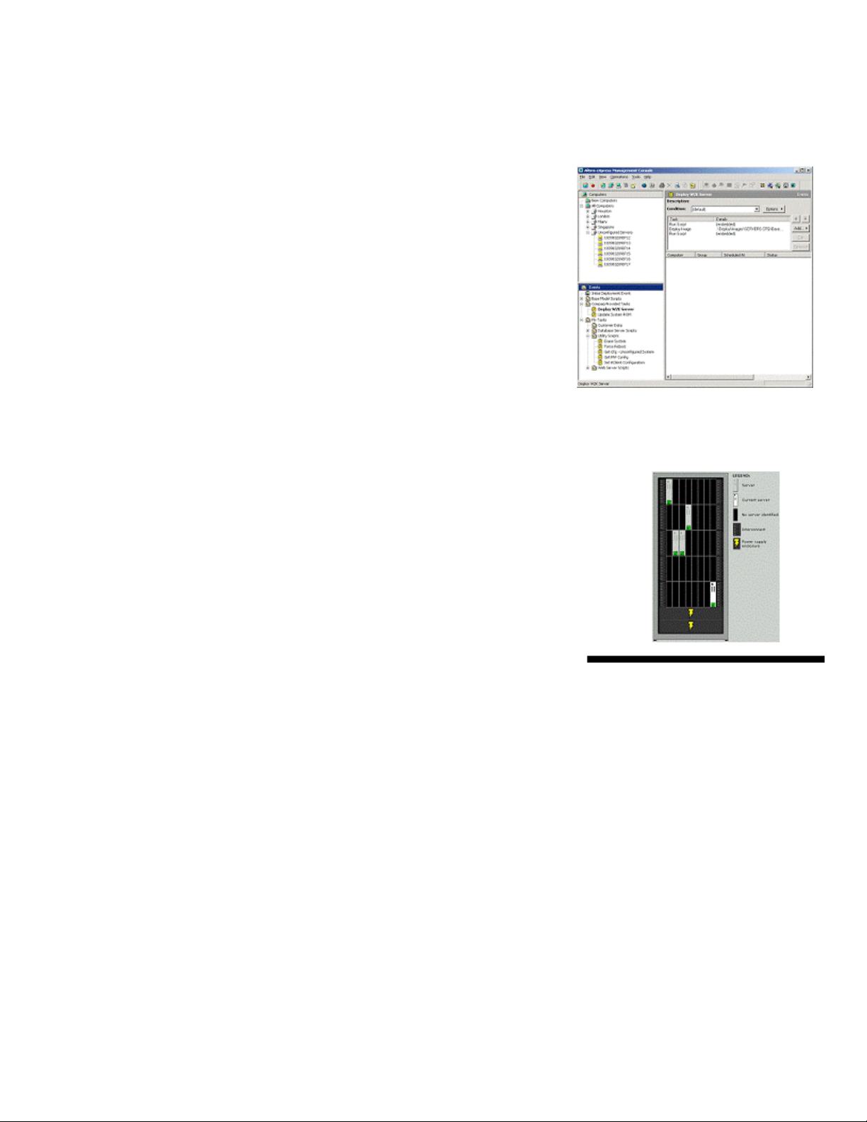
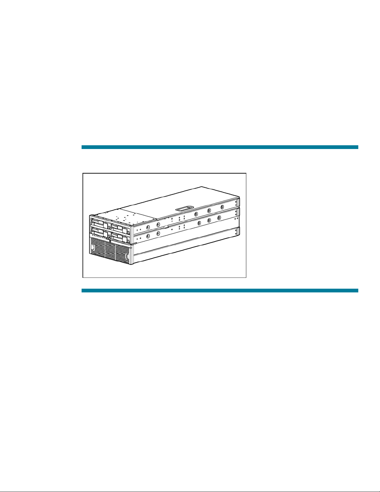
Figure 1 shows an HP BladeSystem p-Class Server Blade Enclosure.
Figure 1. HP BladeSystem standard server blade enclosure
Table 1. Server Blade Components
Item Description
1
2 ProLiant BL40p Server Blade
3 ProLiant BL45p Server Blade
4 ProLiant BL20p, BL25p, or BL60p Server Blades
5 ProLiant BL30p or BL35p Server Blades
HP BladeSystem p-Class Interconnects (2) in a server blade enclosure
(Interconnect Switch shown)
6
Page 7
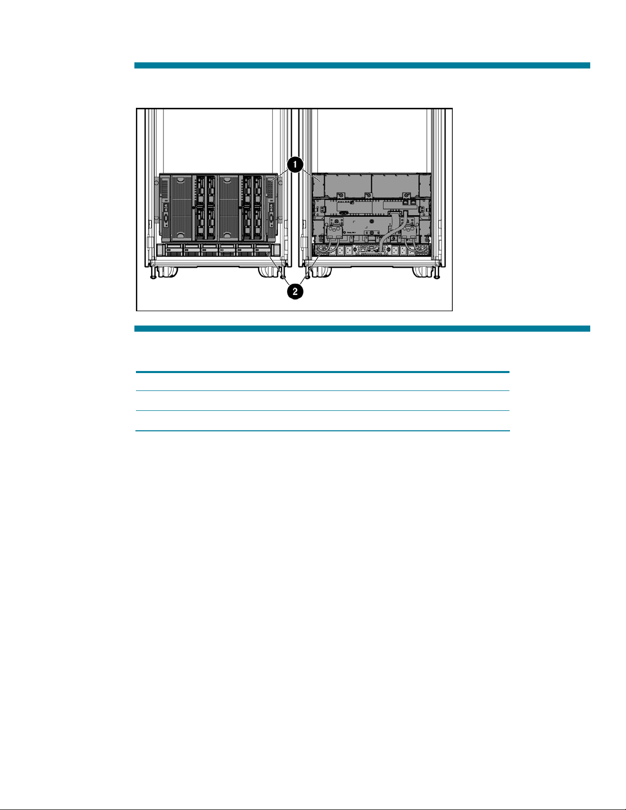
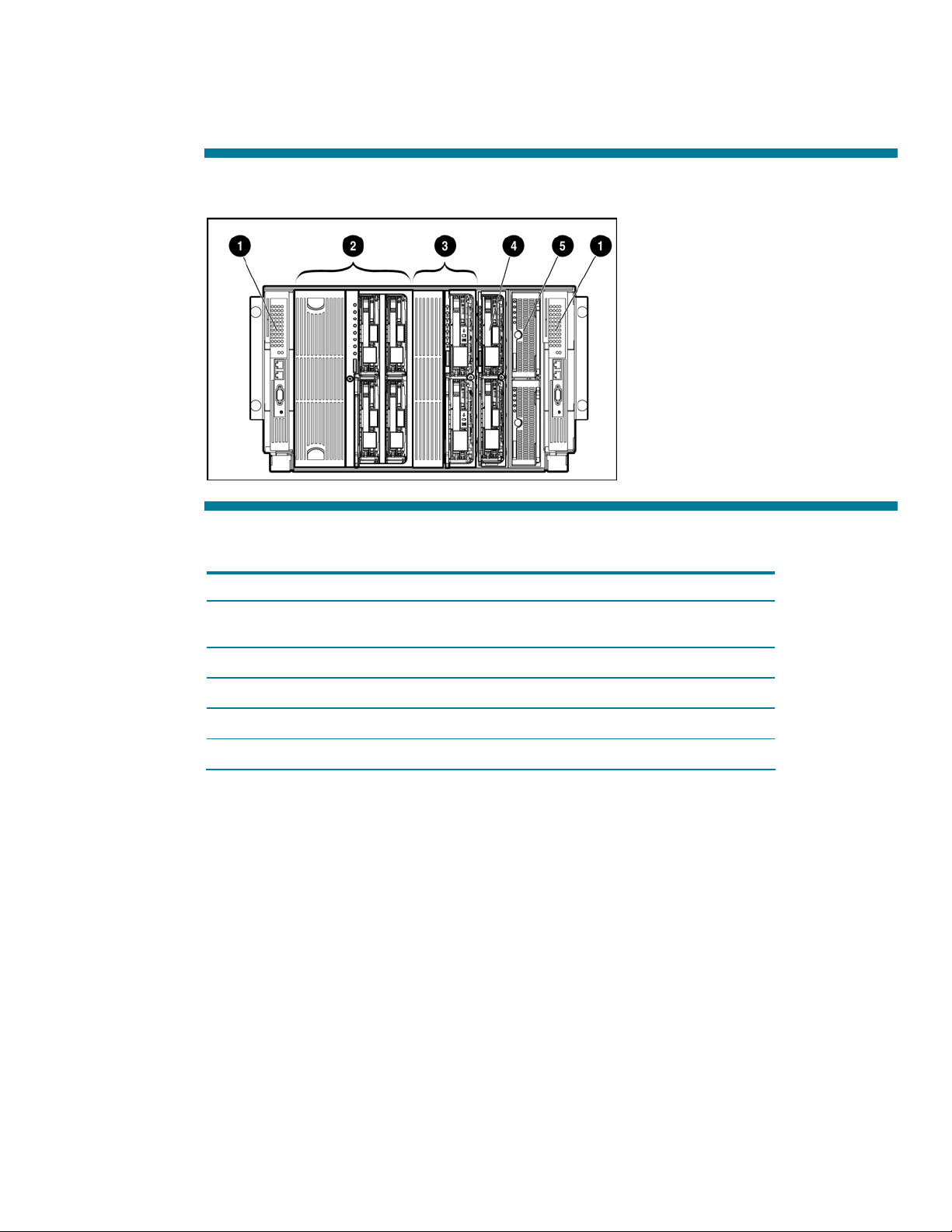
Figure 2 shows an HP BladeSystem p-Class 1U Power Enclosure installation.
Figure 2. HP BladeSystem p-Class Enhanced Server Blade Enclosure and 1U Power Enclosure
Table 2. HP BladeSystem p-Class Enhanced Server Blade Enclosure and 1U Power Enclosure
Item Description
1 Enhanced server blade enclosure
2 1U power enclosure with power supplies
7
Page 8
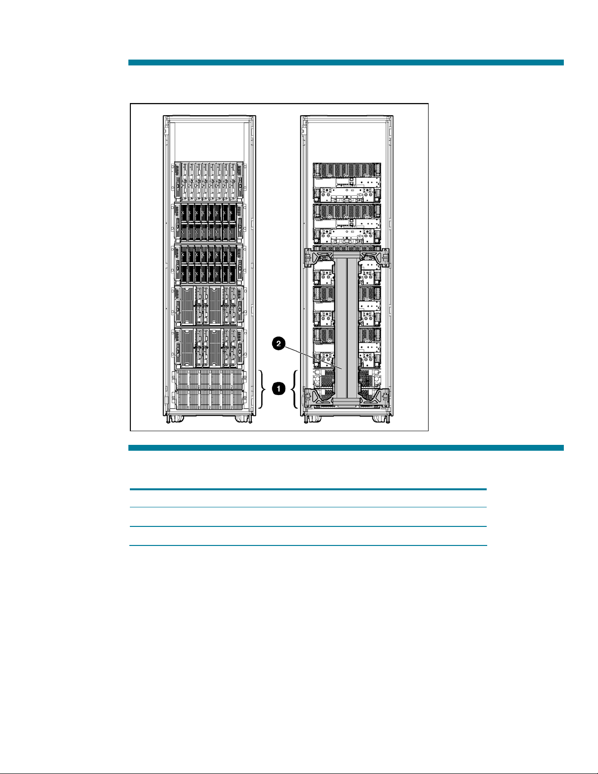
Figure 3 shows an HP BladeSystem p-Class 3U power subsystem installed in a 42U rack.
Figure 3. HP BladeSystem 3U Power Enclosures and power distribution components in a 42U rack
Table 3. Power Subsystem Components
Item Description
1 Hot-plug power supplies in two 3U power enclosures
2 Power distribution (scalable bus bars shown)
8
Page 9
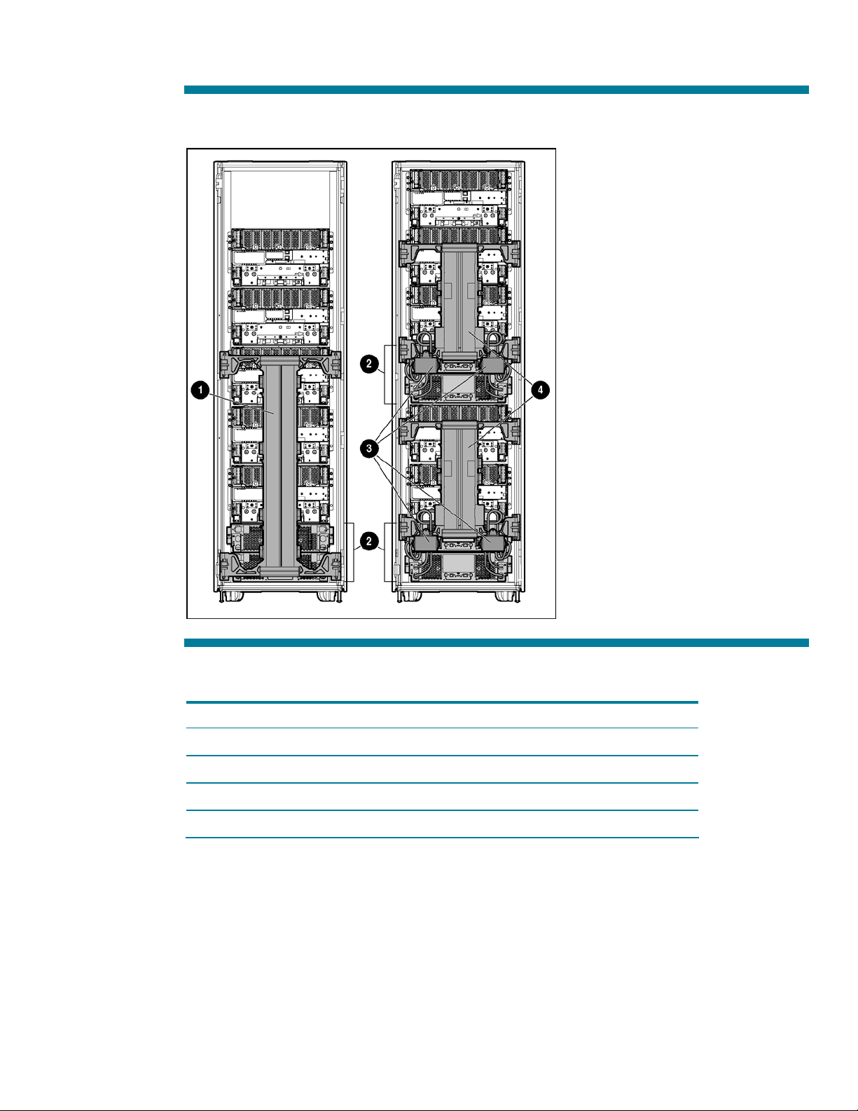
Figure 4 shows scalable and mini bus bar configurations installed in a 42U rack.
Figure 4. Scalable and mini bus bars
Table 4. Scalable and Mini Bus Bars
Item Description
1 Scalable bus bars
2 3U power enclosures
3 Dual Power Input Kit for Mini Bus Bar
4 Mini bus bars
9
Page 10

Hardware components
The HP BladeSystem p-Class solution consists of the following:
• Server blades
• Server blade enclosures
• Network interconnects
• Power subsystem
Table 5. HP BladeSystem Required Components
Required
Components
Server blade
Server blade
enclosure
Network
interconnects
Function
Server blades contain one or more processors, memory, internal and external
storage options, and integrated management. For FC connectivity, server blades
must also be configured with FC card or FC HBA options. ProLiant BL30p and
ProLiant BL35p Server Blades require a p-Class sleeve for mounting in the
enhanced server blade enclosure.
HP BladeSystem p-Class enclosures hold server blades and network interconnect
options. Combinations of different server blades are supported in the same blade
enclosure.
Each enclosure supports a pair of interconnects for network cable management.
The enhanced server blade enclosure also provides a single Ethernet port for
connecting to the iLO interface of every installed server blade.
Some server blade models are supported only in the enhanced server blade
enclosure. Refer to the enclosure compatibility matrix on the HP website,
http://h18004.www1.hp.com/products/blades/components/CompatibilityMatrix.html
HP BladeSystem p-Class interconnects pass the network adapter (NIC) signals from
the server blades to external networks. Several options are available:
• Patch Panel interconnects route each NIC signal individually from the server
blades to the customer network.
• Interconnect switches consolidate the server blade NIC connections to just a
few uplinks, reducing the number of cables needed to connect the solution to
your network.
Both patch panel and interconnect switches are available with or without FC passthrough capability.
Power enclosure
with power
supplies
(Not needed if
using facility
-48 VDC ±10%)
Power distribution
(used only with 3U
power enclosures)
Note: Power requirements for an HP BladeSystem p-Class solution: 200 V to 240 VAC, 30 A or facility DC –48V ±10%
The HP BladeSystem p-Class system offers two power enclosure options:
• The 1U power enclosure provides redundant power for a single server blade
enclosure. It is ideal for remote offices, small businesses, or environments that
do not have three-phase power available.
• The 3U power enclosure and power distribution components provide
redundant power for multiple server blade enclosures. This solution is ideal
for datacenter rack deployment. The 3U power enclosures are available in
single-phase and three-phase models.
Power is carried from the 3U power enclosure(s) to the server blade enclosure(s)
through bus.
Bus bars are available in mini and scalable versions depending on the number of
server blade enclosures being deployed.
10
Page 11
ProLiant BL20p and BL25p series server blades
The ProLiant BL20p and BL25p series Server Blades are ideal for infrastructure and enterprise
applications, including:
• Web
• E-commerce
• Server-based computing
• AV and streaming media
• Messaging front-end and mobility
• Small database
Figure 5. ProLiant BL20p G3 Server Blade
Figure 6. ProLiant BL20p G4 Server Blade
11
Page 12

Table 6. Features of the ProLiant BL20p G3 and ProLiant BL20p G4 Server Blades
ProLiant BL20p G3 Server Blade ProLiant BL20p G4 Server Blade
Processor
Internal storage
Memory
NICs
LEDs
Density
Up to two Intel® Xeon® processors
Up to two universal hot-plug SCSI hard drives
connected to the server through a SCSI Smart
Array 6i Controller provide up to 600 GB
capacity
Four DIMM slots enable installation of up to
8 GB of PC3200 DDR2, ECC, Registered
SDRAM. The memory is 2x1 interleaved for
added performance.
Four general-purpose Gigabit PCI-X 10/100/1000T NICs with Wake-on LAN (WOL) plus one
10/100T NIC dedicated to iLO. The four general purpose NC-Series NICs support PXE and HP
NIC teaming.
LEDs are provided to indicate the following:
- Power
- NIC link and activity
- Server blade health
- Unit identification
Up to eight server blades fit in a 6U server blade enclosure.
Up to two dual-core Intel® Xeon® 5100
sequence processors
Up to two SFF SAS hot-plug hard drives
Eight FBDIMM slots enable installation of up
to 32 GB of PC2-5300 DDR, ECC, Registered
SDRAM. The memory is 2x1 interleaved for
added performance.
12
Page 13
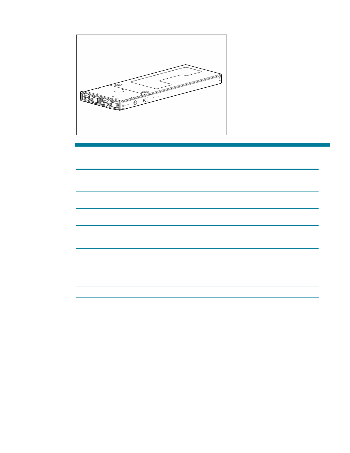
Figure 7. ProLiant BL25p Server Blade
Table 7. Features of the ProLiant BL25p Server Blades
ProLiant BL25p Server Blade
Processor
Internal storage
Memory
NICs
LEDs
Density
Up to two AMD Opteron™ 200 Series processors
Up to two universal hot-plug SCSI hard drives connected to the server through a SCSI Smart
Array 6i Controller provide up to 600 GB capacity
Eight DIMM slots enable installation of up to 16 GB of PC3200 DDR, ECC, Registered SDRAM.
The memory is 2x1 interleaved for added performance.
Four general-purpose Gigabit PCI-X 10/100/1000T NICs with Wake-on LAN (WOL) plus one
10/100T NIC dedicated to iLO. The four general purpose NC-Series NICs support PXE and HP
NIC teaming.
LEDs are provided to indicate the following:
- Power
- NIC link and activity
- Server blade health
- Unit identification
Up to eight server blades fit in a 6U server blade enclosure.
ProLiant BL30p and BL35p series server blades
The ProLiant BL30p and BL35p Server Blades are ideal for enterprise and high-performance
computing applications, including:
• High-performance technical computing applications
• Web
• E-commerce
• Server-based computing
• Messaging front-end
13
Page 14
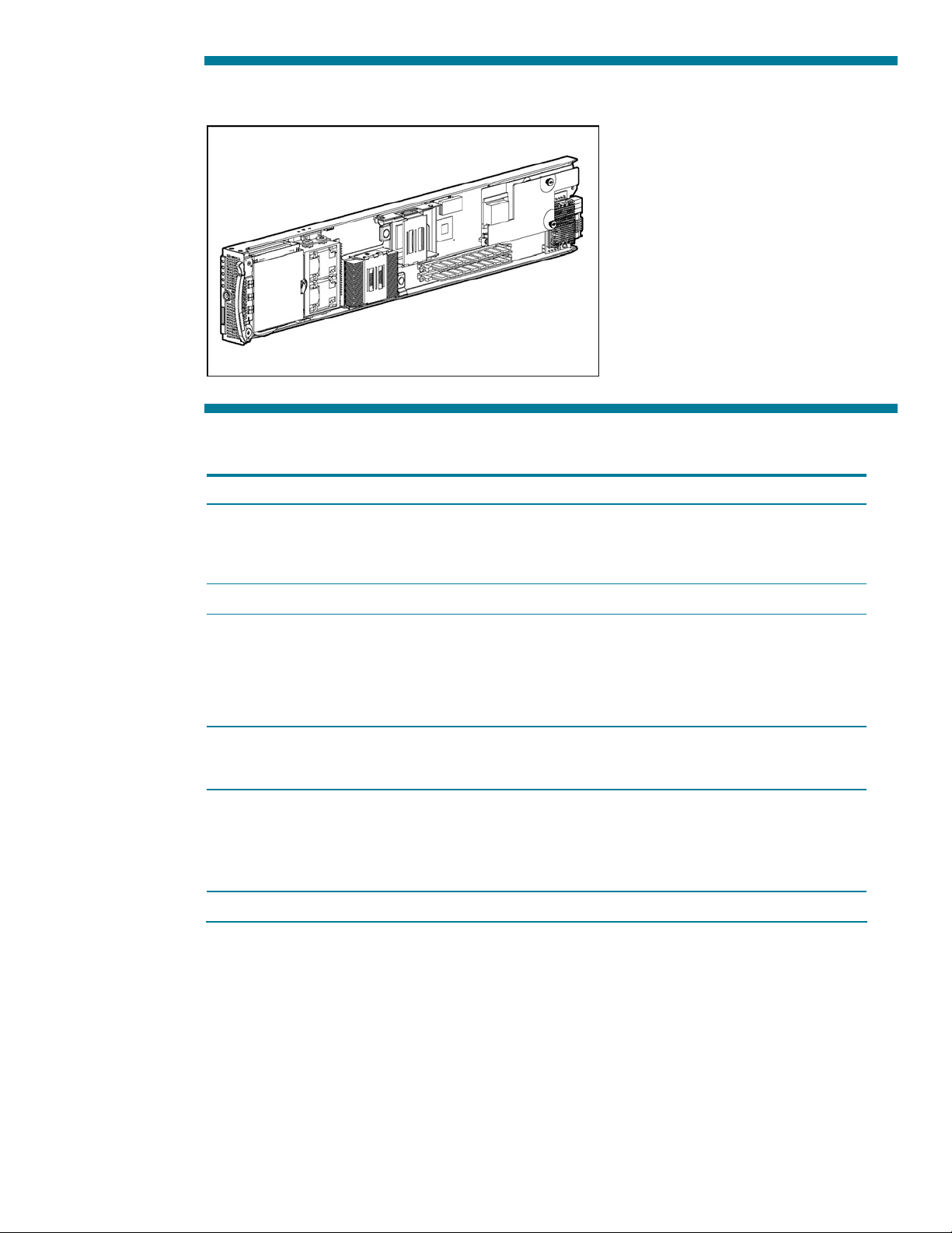
Figure 8. ProLiant BL30p Server Blade
Table 8. Features of the ProLiant BL30p and ProLiant BL35p Server Blades
ProLiant BL30p Server Blade ProLiant BL35p Server Blade
Processor
Internal storage
Memory
NICs
LEDs
Density
Up to two Intel Xeon processors
Up to two small form factor (SFF) ATA hard drives provide up to 120 GB capacity.
Two DIMM slots enable installation of up to
4 GB of PC2100 DDR, ECC, Registered
SDRAM. The memory is 2x1 interleaved for
added performance. Single DIMM noninterleaved memory configurations are also
supported for added flexibility.
Two general-purpose NC7781 Gigabit PCI-X 10/100/1000T NICs with WOL plus one
10/100T NIC dedicated to iLO. The two general purpose NC-Series NICs support PXE and HP
NIC teaming.
LEDs are provided to indicate the following:
- Power
- NIC link and activity
- Server blade health
- Unit identification
Up to 16 server blades fit in a 6U server blade enclosure.
Up to two AMD Opteron™ 200 Series
processors per server blade. Lower power
consumption per server enables use of more
server blades for a given power consumption
Four DIMM slots enable installation of up to
8 GB of PC3200, ECC, Registered SDRAM.
The memory is 2x1 interleaved for added
performance.
14
Page 15
ProLiant BL40p and BL45p Server Blades
The ProLiant BL40p Server Blade is ideal for the following applications:
• Medium to large enterprise databases
• Messaging and collaboration
• IPC Clustering/Failover Clustering
• E-commerce
• Server consolidation
• Enterprise Resource Planning (ERP)
• Customer Relationship Management (CRM)
• Data Warehousing
• Large file/print or domain controllers
Figure 9. ProLiant BL40p Server Blade
15
Page 16
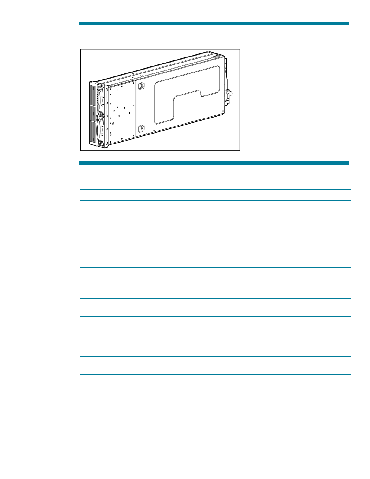
Figure 10. ProLiant BL45p Server Blade
Table 9. Features of the ProLiant BL40p and ProLiant BL45p Server Blade
ProLiant BL40p Server Blade ProLiant BL45p Server Blade
Processor
Internal
storage
Memory
NICs
Expansion
LEDs
Density
Up to four Intel Xeon processors Up to four AMD Opteron 800 Series processors
Up to four universal hot-plug SCSI hard drives
connected to the server through a Smart Array 5i
controller with Battery Backed Write Cache
Enabler provide up to 1200 GB capacity
Six DIMM slots enable installation of up to 12 GB
of PC2100 DDR, ECC, Registered SDRAM. The
memory is 2x1 interleaved for added performance.
Five general-purpose PCI-X 10/100/1000T NICs
with WOL plus one 10/100T NIC dedicated to
iLO. The five general purpose NC-Series NICs
support PXE and HP NIC teaming.
Two PCI-X slots for redundant FC HBAs and certain
Smart Array controllers
LEDs are provided to indicate the following:
- Power
- NIC link and activity
- Server blade health
- Unit identification
Up to two server blades fit in a 6U server blade
enclosure.
Up to two universal hot-plug SCSI hard drives
connected to the server through a Smart Array 6i
controller with Battery Backed Write Cache
Enabler provide up to 600 GB capacity
Sixteen DIMM slots enable installation of up to 32
GB of PC3200 DDR, ECC, Registered SDRAM. The
memory is 2x1 interleaved for added performance.
Four general-purpose PCI-X 10/100/1000T NICs
with WOL plus one 10/100T NIC dedicated to
iLO. All five general purpose NC-Series NICs
support PXE and HP NIC teaming.
No expansion slots, FC connectivity supported with
a dual-port Fibre Channel adapter option
Up to four server blades fit in a 6U server blade
enclosure.
16
Page 17

Integrity BL60p Server Blade
The Integrity BL60p Server Blade is ideal for the following applications:
• HP-UX v11 applications
• HP-UX legacy application consolidation
• HP-UX test and development, particularly PA-RISC to Itanium migration
• Database tier in applications requiring enterprise class HP-UX Unix
Figure 11. Integrity BL60p Server Blade
Table 10. Features of the Integrity BL60p Server Blade
ProLiant BL60p Server Blade
Processor
Internal
storage
Memory
NICs
Density
Up to two Intel® Itanium2 1.6-GHz 3-MB cache processors
Up to two universal hot-plug SCSI hard drives connected to the server through a
SCSI Smart Array 6i Controller provide up to 600 GB capacity
Four DIMM slots enable installation of up to 8 GB of PC2100 DDR SDRAM running
at 133MHz and 266MHz transfers/second, memory must be installed in pairs,
Chip Sparing is enabled if all four DIMMs are the same size/density
Six network connectors total:
• Four PCI-X Gigabit embedded Ethernet connectors consisting of two Broadcom
5704s with one 10/100T NIC dedicated to management
• Two embedded Fibre Channel connectors (2-Gb per connector)
Up to eight server blades fit in a 6U server blade enclosure
17
Page 18

ProLiant and Integrity BL p-Class server blade SAN connectivity
The ProLiant and Integrity BL p-Class server blades are optimized for HP StorageWorks arrays, and
can attach to select third-party SAN solutions. In addition, the server blades can integrate with "fused"
NAS and SAN configurations, providing the ability to work in file and block environments seamlessly.
HP StorageWorks arrays include:
• StorageWorks MSA 1000
• StorageWorks Enterprise Virtual Array (EVA)
• StorageWorks EMA/MA arrays
• StorageWorks XP
Select Hitachi and EMC models are compatible.
All StorageWorks models listed support SecurePath for multi-path functionality.
All ProLiant and Integrity server blades support redundant FC SAN connections. With the exception of
the ProLiant BL40p Server Blade, all BL p-Class server blades support dual port FC adapter options.
The ProLiant BL40p Server Blade has two 64-bit, 100-MHz PCI-X slots that enable redundant FC SAN
connectivity using standard host-bus adapter cards. The Integrity BL60p has dual, 2-Gb Fibre Channel
connectors embedded.
FC connectivity with ProLiant BL20p, BL25p, BL30p, BL35p, BL45p series and Integrity BL60p server blades
FC signals are routed from the configured server blade through the server blade enclosure backplane
to the interconnect modules. Optical transceivers added to the interconnect modules provide
connectivity to the external fabric.
For FC SAN connectivity with ProLiant BL20p, BL25p, BL30p, BL35p, and BL45p series server blades,
an interconnect kit option with FC pass-through capability is required. Both the ProLiant BL p-Class RJ45 Patch Panel 2 and the ProLiant BL p-Class GbE2 Interconnect Switch with the GbE2 Storage
Connectivity Kit option provide FC SAN pass-through capability.
The dual port FC adapter option kits each include two SFF transceivers with LC connectors. These SFF
transceivers are installed in the RJ-45 Patch Panel 2 transceiver slots. The SFF transceivers are
universal and can be used with the RJ-45 Patch Panel 2, the GbE2 Interconnect Switch, or Cisco
Gigabit Ethernet Switch Module (CGESM) (with GbE2 Storage Connectivity Kit).
Refer to the QuickSpecs for your specific model of server blade to ensure that you are using the
correct dual port FC adapter option kit. Each server blade model has a unique FC adapter option kit.
For the server blade QuickSpecs, visit the HP website at http://www.hp.com/go/bladesystem
.
18
Page 19

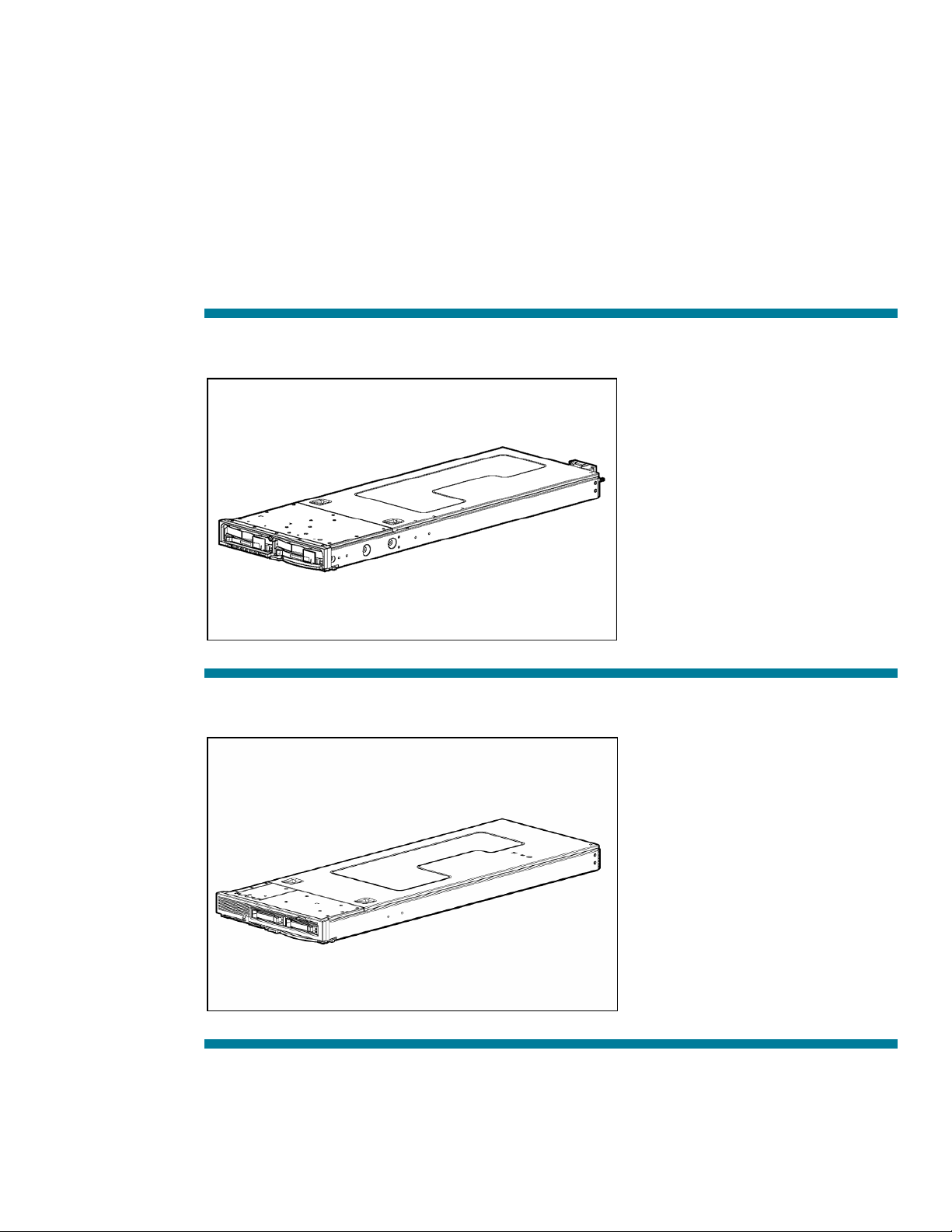
Figure 12. BL20p G3 Dual Port FC Mezzanine Card (installed)
Figure 13. BL25p/BL45p Dual Port FC Adapter
Figure 14. The BL30p/BL35p Dual Port FC Adapter (installed)
19
Page 20

FC connectivity with ProLiant BL40p Server Blades
ProLiant BL40p Server Blades have two external PCI-X slots for use with standard FC HBAs. When
configuring ProLiant BL40p Server Blades with FC HBAs, the FC signals are not routed through the
signal backplane. Refer to the documentation included with the ProLiant BL40p Server Blade for
details.
Figure 15. RJ-45 Patch Panel 2 installed in a server blade enclosure with ProLiant BL40p Server Blades and FC option
Table 11. Enclosure Components
Component Description
1 RJ-45 Patch Panel 2
2 SFF transceiver
Specific requirements for attaching ProLiant BL30p and ProLiant BL35p Server Blade to FC SANs
The ProLiant BL30p/BL35p Dual Port FC Adapter Option is based on the Logic ISP2312 chipset. This
chipset carries forward all the features of the ProLiant BL20p, ProLiant BL25p, and ProLiant BL45p
Dual Port FC Mezzanine Cards and is an industry standard solution. The features of the Dual Port FC
Adapter include:
• RDP scripted installation for Microsoft® Windows® and Linux
• Boot capability from SAN disk or LUN
• Blade bay to FC switch compatibility established by the server blade
• High availability through redundant paths
The ProLiant BL30p/BL35p FC Adapter has a different subvendor ID than the ProLiant BL20p, ProLiant
BL25p, and ProLiant BL45p Dual Port FC Mezzanine Cards. Because the Windows driver is
subvendor ID sensitive, a new backward compatible driver was introduced with the ProLiant BL30p
and the ProLiant BL35p Server Blades. Linux drivers are not subvendor ID sensitive, so the currently
available Linux drivers are compatible.
20
Page 21

FC port aggregation is required to accommodate the increased number of server FC HBA ports and
to maintain compatibility with the available enclosure backplane signals and interconnect ports. The
p-Class sleeve aggregates the four paths from two ProLiant BL30p or ProLiant BL35p Server Blades
into two physical paths. This innovative port aggregation technology enables up to 16 physical FC
ports from the Patch Panel 2, GbE2 Interconnect Switch, or Cisco Gigabit Ethernet Switch Module to
connect directly to the customer external FC SAN switch. ProLiant BL30p and ProLiant BL35p FC
implementations require the FC SAN switch to support FC-AL public loop login. With few exceptions,
notably McData core switches, most FC switches provide this support. All Brocade SAN switches and
most Cisco SAN devices support this feature.
NOTE: The FC LED on the Patch Panel 2 or GbE2 Interconnect Switch does not display a live link
when using the enhanced server blade enclosure. Port activity information can be obtained from the
FC SAN switch or by using QLogic SANsurfer Blade Management software.
HP BladeSystem p-Class Server Blade Enclosure
ProLiant BL p-Class server blades and network interconnects are housed in a 6U server blade
enclosure. The blades slide into the blade enclosure backplanes for power and network connections.
Each blade enclosure has eight server blade bays in the center of the enclosure and two interconnect
bays at each end. The two interconnect bays are populated with either patch panel interconnects (for
direct signal pass-through) or interconnect switches (for network cable reduction). The middle eight
bays support server blades.
The two types of server blade enclosures are: standard server blade enclosures and enhanced server
blade enclosures. Some server blade models are supported only in enhanced server blade enclosures.
For details, refer to the enclosure compatibility matrix at
http://www.hp.com/go/bladesystem/enclosure/compatability
The enhanced server blade enclosure provides the following:
• A server blade management module that simplifies setup and management by:
– A single physical iLO port for all installed server blades that provides up to 16:1 management
cabling consolidation
– Static IP Bay Configuration for automated configuration of iLO addresses
• Support for all ProLiant BL30p and ProLiant BL35p Server Blades, as well as support for all current
and future ProLiant BL20p, ProLiant BL25p, ProLiant BL40p, and ProLiant BL45p series server blades
• Support for all current and future network interconnect options, including the new CGESMs
21
Page 22

Figure 16 is a front view of the HP BladeSystem p-Class Blade Enclosure.
Figure 16. Server blade enclosure front view
Features of the server blade enclosure include:
• Management communication—The server blade management module reports thermal, power, and
protection fuse events to all server blades in the blade enclosure. The management module also
facilitates power sharing across enclosures and provides asset and inventory information. On
enhanced server blade enclosures, the server blade management module provides a single RJ-45
connector for accessing all installed server blade iLO interfaces. This feature greatly reduces the
number of network cables needed for management.
• Availability—The server blade management module is hot-plug and can easily be replaced without
interruption to server blades or interconnects. Both electrical and mechanical fuses in the backplane
power feed to each bay protect the power backplane from possible electrical damage.
• Toolless installation—Easily installed with spring-loaded rack rails and thumbscrews. Rack rails are
common between the server blade enclosure and the power enclosure.
• Toolless serviceability—Power backplane, data backplane, and server blade management module
are serviceable without tools and without removing the server blades and interconnects from the
enclosure or removing the blade enclosure from the rack.
22
Page 23

Figure 17 is a rear view of the HP BladeSystem p-Class Enhanced Server Blade Enclosure.
Figure 17. Enhanced server blade enclosure rear view
HP BladeSystem p-Class Blade Sleeve
The HP BladeSystem p-Class Sleeve is required to support ProLiant BL30p and ProLiant BL35p Server
Blades in the enhanced server blade enclosure. The sleeve is for use with these server blades only.
Figure 18. HP BladeSystem p-Class Blade Sleeve
Features of the HP BladeSystem p-Class Blade Sleeve include:
• Holds up to two ProLiant BL30p or ProLiant BL35p Server Blades in any combination
• Installs into any of the eight blade bays in an enhanced server blade enclosure
23
Page 24

HP BladeSystem p-Class network interconnect options
Each server blade enclosure must be configured with a pair of network interconnects. These
interconnects slide into the front of the blade enclosure and collect Ethernet and FC (except ProLiant
BL40p Server Blades) signals from all the installed server blades.
Figure 19. HP BladeSystem p-Class Enclosure interconnect locations
Two general categories of interconnect options are available depending on your preferences and
environment:
• RJ-45 Patch Panel interconnects collect Ethernet signals from each server blade and provide
an external RJ-45 connector for cabling to each individual server blade NIC. The RJ-45 patch panel
2 option enables individual sever blade FC signals to pass through the interconnect. Benefits of the
RJ-45 Patch Panel options include:
– Connects signals directly to your LAN and SAN
– Offers the lowest blade solution price
– Requires no software or management
– Provides FC signal pass-through (RJ-45 Patch Panel 2 only)
• Interconnect Switches consolidate the Ethernet signals from the server blades to a smaller set of
external copper-based or fiber-based uplink ports for connection to your network. Similar to the
RJ-45 Patch Panel 2, select interconnect switch options pass through individual FC signals. Benefits
of the interconnect switch options include:
– Reduces the number of network cables needed for each server blade enclosure
– Reduces the number of ports used on core network switches
– Enables fully manageable and configurable interconnects
– Provides FC signal pass-through (GbE2 Interconnect and Cisco Gigabit Ethernet Switches only)
The HP BladeSystem p-Class interconnect options are shown in Table 12.
24
Page 25

Table 12. HP BladeSystem p-Class interconnect options
Interconnect Option FC Pass Through
Cisco Gigabit Ethernet Switch Module for HP BladeSystem p-Class Yes
HP BladeSystem p-Class GbE2 Interconnect Switch Yes
HP BladeSystem p-Class GbE Interconnect Switch No
HP BladeSystem p-Class RJ-45 Patch Panel No
HP BladeSystem p-Class RJ-45 Patch Panel 2 Yes
Cisco Gigabit Ethernet Switch Module for HP BladeSystem p-Class
The CGESM is a 24-port Gigabit Ethernet Switch that significantly reduces the number of Ethernet
network cables needed for each server blade enclosure. It is designed for applications that require
Gigabit Ethernet network adapter consolidation to 1000 MB/s, advanced network functionality, and
FC signal pass-through for server blades that use internal FC adapter options.
Figure 20. CGESM components
Table 13. GbE2 Interconnect Switch Components
Item Description
1 CGESM Switch
2
3 SFP connector for copper and FC Ethernet
SAN (OctalFC) interconnect module (optional) for FC
pass-through
CGESM kit options include the following:
• A hot-plug fully managed, layer 2+ CGESM and two Copper Small Form Factor Pluggable (SFP)
modules with RJ-45 connectors
• A CGESM module with no SFPs
An optional kit to support Fiber SFPs is also available for Fiber gigabit Ethernet connectivity.
25
Page 26

Each CGESM reduces up to 16 internal server blade network NIC ports to six external Ethernet ports.
Because each external Ethernet port can communicate to all the server blades, as few as one external
port per enclosure may be used to connect to your network.
In addition to providing up to 32-to-1 network cable reduction per server blade enclosure, the
CGESM kit offers the following features:
• Cisco IOS based on Catalyst 2970 Enhanced Image.
• Gigabit Ethernet performance on all switch ports.
• Advanced network feature support and system availability including spanning tree per VLAN,
9k jumbo frames, RADIUS/TACAS+, IGMP Snooping, QoS, Link Aggregation Control Protocol
(LACP), redundant syslog servers, redundant operating system firmware images and configuration
files in memory.
For more detailed information about the specific set of features supported on this interconnect option,
refer to the interconnect website, http://www.hp.com/go/bladesystem/interconnects/
ProLiant BL p-Class GbE2 Interconnect Switch
The ProLiant BL p-Class GbE2 Interconnect Switch is a 24-port Gigabit Ethernet Switch that
significantly reduces the number of Ethernet network cables needed for each server blade enclosure
and is designed for applications that require network adapter consolidation to 1000 Mb/s (Gigabit
Ethernet), advanced network functionality, and FC signal pass-through for server blades that use
internal FC adapter options.
Figure 21. GbE2 Interconnect Switch components
Table 14. GbE2 Interconnect Switch Components
Item Description
1 GbE2 Interconnect Switch
2
3
SAN (OctalFC) interconnect module (optional) for pass-through
of FC
GbE2 LAN interconnect module (for Ethernet signal
consolidation)
26
Page 27

The GbE2 Interconnect Kit contains two hot-plug, fully managed, layer 2 GbE2 Interconnect Switches
and two LAN interconnect modules. The GbE2 Interconnect Kit is available with either copper-based
(CgbE) or fiber-based (FgbE) uplinks.
Each GbE2 Interconnect Switch reduces up to 16 internal server blade network NICs ports to six
external Ethernet ports. Because each external Ethernet port can communicate to all the server blades,
as few as one external ports (per enclosure) may be used to connect to your network.
In addition to providing up to 32-to-1 network cable reduction per server blade enclosure, the GbE2
Interconnect Kit offers the following features:
• Gigabit Ethernet performance on all switch ports.
• Advanced network feature support and system availability including spanning tree per VLAN, 9k
jumbo frames, RADIUS, redundant syslog servers, redundant operating system firmware images and
configuration files in memory.
• Optional pass-through of FC signals for server blades configured with internal FC adapter options.
For more detailed information about the specific set of features supported on this switch, refer to the
interconnect switch website:
refer to the interconnect website, http://www.hp.com/go/bladesystem/interconnects/
ProLiant BL p-Class GbE Interconnect Switch
The ProLiant BL p-Class GbE Interconnect Kit reduces the number of network cables needed for each
server blade enclosure and consolidates the server blade network adapter signals to 100 Mb/s.
The GbE Interconnect Kit includes two hot-plug, fully managed layer 2 Ethernet switches and two rearmounted, 4-port LAN interconnect modules. The GbE Interconnect Kit is available with either copperbased (C-GbE) or fiber-based (F-GbE) uplinks.
27
Page 28

Figure 22. GbE Interconnect Switch components
Table 15. GbE Interconnect Switch Components
Item Description
1 GbE Interconnect Switch
2 GbE LAN Interconnect Module
In addition to providing up to 32 FC to 1GB network cable reduction per server blade enclosure, the
GbE Interconnect kit offers the following features:
• DLink Switch OS.
• Gigabit Ehternet performance on two uplink switch ports.
• Advanced network feature support and system availability, including QoS, IGMP, and MAC-based
priority.
For more detailed information about the specific set of features supported on this switch, refer to the
HP BladeSystem interconnect website, http://www.hp.com/go/bladesystem/interconnects/
28
Page 29

ProLiant BL p-Class RJ-45 Patch Panel
The RJ-45 Patch Panel brings all server blade NIC signals out as individual RJ-45 connectors.
Figure 23. RJ-45 Patch Panel components
Table 16. RJ-45 Patch Panel Components
Item Description
1 RJ-45 Patch Panels
2 RJ-45 Interconnect Module (10-connector)
3 RJ-45 Interconnect Module (6-connector)
Features of the RJ-45 Patch panel include:
• Economical solution for providing pass through of up to 32 NIC signals
• Completely passive–requires no software or management
• Fault tolerance–Half of the signals from each server blade go to the left interconnect and half go to
the right interconnect, providing separate redundant paths to the network(s).
29
Page 30

ProLiant BL p-Class RJ-45 Patch Panel 2
The RJ-45 Patch Panel 2 functions as an Ethernet pass-through and enables pass-through functionality
for FC signals from all server blades configured with internal FC adapter options.
Figure 24. RJ-45 Patch Panel 2 components
Table 17. RJ-45 Patch Panel 2 Components
Item Description
1 RJ-45 Patch Panel 2
2 Patch Panel 2 Interconnect Module (10-connector)
3 Patch Panel 2 Interconnect Module (6-connector)
Each RJ-45 Patch Panel 2 Interconnect (a pair is included in each option kit) has eight FC SFF
transceiver slots located on the front. Features of the RJ-45 Patch Panel 2 include:
• Economical solution for providing pass through of up to 32 NIC and 32 FC signals.
• Completely passive–requires no software or management.
• Fault tolerance–Half of the signals from each server blade go to the left interconnect and half go to
the right interconnect, providing separate, redundant paths to the network(s).
• A cable channel facilitates routing the optical cables to the back of the server blade enclosure.
• Each dual port FC adapter option includes two SFF transceivers with LC connectors. These optical
transceivers are universal and are installed in the front-panel transceiver slots located on the front of
the RJ-45 Patch Panel 2.
30
Page 31

HP BladeSystem p-Class power subsystem
HP provides two power subsystem alternatives to accommodate various environments and customer
needs. These two options are enclosure-based power and rack-centralized power. All server blades,
interconnect options, and management tools are fully compatible with either power subsystem.
Enclosure-based power
The new HP BladeSystem p-Class 1U Power Enclosure provides hot-plug, fully redundant power for a
single server blade enclosure containing any mix of server blades and interconnects. This option is
ideal for small blade deployments such as in remote or branch offices or small and mid-size
businesses.
Figure 25. HP BladeSystem 1U Power Enclosure
Rack-centralized power
The HP BladeSystem p-Class 3U power subsystem provides hot-plug, fully redundant power for
multiple enclosures that would typically be deployed in racks in a datacenter environment.
Rack-centralized power provides an efficient way to support a large number of blades while
eliminating power cables and the clutter and cost of PDUs associated with traditional power schemes.
The 3U rack-centralized power subsystem includes the power supplies, 3U power enclosure, and a
power distribution option. The HP BladeSystem p-Class system can be powered from single-phase or
three-phase AC power or from –48 VDC power sources.
Power supplies
The power supplies for the 3U solution convert 200–240 VAC to –48 VDC to power server blades
and interconnect switches and are housed in a 3U power enclosure. The power supplies are
front-accessible, hot-pluggable, and can be configured redundantly. The power enclosures are rackmounted below the server blade enclosures that they support.
31
Page 32

HP offers two models of 3U power enclosure that are designed to meet installation power demand
and redundancy requirements, depending on the number and type of server blades you plan to
deploy:
• Single-phase HP BladeSystem 3U p-Class Power Enclosure (holds up to four power supplies)
• Three-phase HP BladeSystem 3U p-Class Power Enclosure (holds up to six power supplies)
Because the three-phase power enclosure holds up to six power supplies, it supports more server
blades and interconnect switches than the single-phase power enclosure. It is generally recommended
for the HP BladeSystem p-Class solution. For more detailed information about the specific power
enclosure options and power planning tools, refer to the HP BladeSystem p-Class website:
http://www.hp.com/go/bladesystem
Figure 26. HP BladeSystem p-Class 3U Power Enclosure (three phase shown) with power supplies
Power distribution
Power is carried from the power supplies in the power enclosure(s) or from the local –48V facility DC
power source to the server blade enclosures through either bus bars or a bus box. Bus bars are used
to support multi-enclosure deployments while the bus box is used to power a single server blade
enclosure, such as in a lab or test system environment.
The bus bars are attached directly to the RETMA rails in a rack. Hinges on the bus bars provide easy
rear access to the interconnect modules, network cables, server blade management modules, and
power management modules.
The three specific HP BladeSystem p-Class power distribution options are summarized in Table 18.
Deploying a full 42U rack of ProLiant BL p-Class server blades requires using two pairs of mini bus
bars.
32
Page 33

Table 18. HP BladeSystem p-Class Power Distribution Options
Solution Power Enclosures
Supported
Scalable bus bar 2 5 36U
Mini bus bar 2 1 3 24U
Power bus box 1 1 9U
1. To attach two power enclosures to a mini bus bar, the Dual Power Input Kit for Mini Bus Bar option is required.
2. To deploy a full 42U rack of HP BladeSystem p-Class server blades requires stacking two pairs of mini bus bars.
NOTE: When using an Enhanced Server Blade Enclosure, two power enclosures are required for power redundancy.
Server Blade Enclosures
Supported
Maximum Rack Space
Occupied
2
For more detailed information about the specific power distribution options and power planning tools,
refer to the
HP BladeSystem website at http://www.hp.com/go/bladesystem
Figure 27. Scalable and mini bus bars
33
Page 34

Table 19. Scalable and Mini Bus Bars
Item Description
1 Scalable bus bars
2 3U power enclosures
3 Dual Power Input Kit for Mini Bus Bar
4 Mini bus bars
HP BladeSystem p-Class 1U and 3U power subsystem features
• Availability—high availability, fully redundant configurations, including hot-plug redundant power
supplies, redundant AC inputs, and a hot-plug power management module that operates
independently of the server blades and interconnects
In the 3U power subsystem, DC circuit breakers enable shutting off the power to individual server
blade enclosures for safe physical access without interrupting the operation of other blade
enclosures.
• Intelligent infrastructure— The hot-plug power management module monitors the power subsystem
components and regulates the power-up sequence of newly installed server blades and
interconnects switches. The power management module is cabled to the server blade enclosure
management module(s) to facilitate communication of management information, such as server
blade and interconnect location, power supply budget, and health status.
• Investment protection—All current and future server blades and interconnect options can be used
with any of the power subsystem options.
• Tooless installation and serviceability—power enclosures are easily installed with spring-loaded
rack rails and thumbscrews.
34
Page 35

HP BladeSystem p-Class Diagnostic Station
The HP BladeSystem p-Class Diagnostic Station enables a server blade or interconnect switch to be
powered up outside of a server blade enclosure for testing or diagnostic purposes. The diagnostic
station contains a power supply and connectors for data transfer between the server blade or
interconnect switch and a client device (such as a PC, notebook, or workstation). The client provides
the keyboard, video, mouse, and diskette interface and facilitates the use of the iLO remote console.
Figure 28. Diagnostic Station
The diagnostic station enables the following tasks to be performed outside of a server blade
enclosure:
• Power up a server blade or interconnect switch
• Observe external LEDs
• Test NIC and interconnect switch port activity
• Configure a server blade
• Configure an interconnect switch, including VLANs and security
• Load software on a server blade
• Configure an interconnect switch to download an applicable configuration file
• Test a server blade or interconnect switch after installing an option or upgrade
• Diagnose a server blade using iLO
• Diagnose the interconnect switch using the front panel Ethernet and RS-232 ports
35
Page 36

HP BladeSystem p-Class diagnostic and local I/O cables
HP BladeSystem p-Class systems are optimized for use with HP ProLiant Essentials Rapid Deployment
pack (RDP) for software installation and deployment from a centralized deployment console. Local
console and I/O connections are available through diagnostic and local I/O cables.
• Diagnostic cable—A diagnostic connector is on the front of the some server blade models. This
connector is used to access the iLO of a server blade by connecting a client device directly to the
server blade.
• Local I/O cable—A local I/O cable can be used with server blade models that have an I/O cable
icon next to the I/O port on the front of the server blade. The I/O connector provides ports for
video, up to two USB devices, kernel debug, serial, and iLO Ethernet connectivity.
Figure 29. Diagnostic and Local I/O Cables and I/O cable Icon
Refer to the documentation that shipped with your server blade for more information on the use of the
diagnostic or local I/O cable.
36
Page 37

HP BladeSystem Management Software overview
HP highly recommends that you become familiar with the tools shown in Table 20, which are used to
set up, configure, and manage the HP BladeSystem solution. This table serves as a getting started
checklist and as a pointer to more information about these tools.
The Integrity BL60 server blade supports only the HP-UX 11i operating system. There are management
differences for this server. Please see http://www.hp.com/products1/servers/integrity/index.html
for access to complete BL60p support documentation.
Table 20: Key Management Components
Tool Function Where to Find
SmartStart software
HP ProLiant
Essentials RDP
HP Systems Insight
Manager (HP SIM)
Integrated LightsOut (iLO)
SmartStart software is used to initialize and
configure one or more management servers that
make up the HP BladeSystem management
environment.
For more information, refer to
http://www.hp.com/servers/smartstart/
RDP is used to automate the process of deploying
and provisioning server blade software and
interconnect switch configuration. This enables
management of multiple server blades and
interconnects, and facilitates the development of
pre-tested server builds and interconnect
configurations.
For more information, refer to
http://www.hp.com/servers/rdp
For more information, refer to
http://www.hp.com/go/hpsim/
For ProLiant BL p-Class server blades, iLO
provides advanced levels of remote
manageability. This guide details iLO functions in
various steps of initial configuration, as well as for
common operational tasks. For more information,
refer to
http://www.hp.com/servers/ilo/
/
Located in the HP ProLiant
Essentials Foundation Pack shipped
with each HP BladeSystem blade
enclosure
Optional product shipped with
HP BladeSystem enclosures, or
available for download at the RDP
website.
A license fee is required for use of this
product.
Located in the
HP ProLiant Essentials Foundation Pack,
shipped with HP BladeSystem
enclosures.
Standard with ProLiant BL p-Class server
blades.
Array
Configuration
Utility (ACU)
ACU is used to set up local drive controllers and
RAID environments for ProLiant BL20p, BL25p,
BL40p, and BL45p Server Blades.
ACU is also used with the HP StorageWorks
Modular SAN Array 1000 (MSA1000) storage
system to set up the SAN drive controller, RAID
environment, and logical drives for connection to
ProLiant BL server blades.
This guide provides instructions for the use of this
tool during initial server setup and ProLiant BL
system SAN setup.
Located in the HP ProLiant Essentials
Foundation Pack, shipped with
HP BladeSystem enclosures.
Available for download at
http://h18004.www1.hp.com/
products/servers/
proliantstorage/softwaremanagement/acumatrix/
Continued…
37
Page 38

Table 20: Key Management Components (continued)
Tool Function Where to Find
HP BladeSystem
Interconnect Switch
configuration and
management
software
ProLiant BL Interconnect Switches provide both
command line and Web-based interfaces for
configuration and management of interconnect
switches within server blade enclosures. For more
information, refer to:
HP BladeSystem p-Class GbE and GbE2
Interconnect Switches at
Ships with HP BladeSystem p-Class
Interconnect Switch Kits.
http://h18004.www1.hp.com/products/se
rvers/proliant-bl/p-class/20p/bl-pinterconnect-switch.html
F5 Networks Big-IP
Blade Controller
software
The F5 Big-IP Blade Controller software provides
load balancing and L3-7 traffic management
functions for the ProLiant BL system environment.
The software, once installed on a server blade,
converts the server blade into an F5 Big-IP
appliance. The HP BladeSystem System Common
Procedures Guide provides setup instructions and
uses the F5 software in several common
operational tasks.
Optional software available from F5
Networks, Inc., at
http://www.f5.com
A license from F5 Networks is required.
HP BladeSystem p-Class operating system installation options
ProLiant BL20p, BL25p, BL30p, BL35p, and BL45p series server blades
The operating system for a server blade may be deployed using one of the following options:
• RDP for installation of the operating system on one or many blades simultaneously from a
centralized deployment console
• iLO with Advanced Pack features enables installation of an operating system using the iLO remote
console and virtual floppy or virtual CD-ROM features
• Directly cable KVM and removable media devices to a server blade using the local I/O cable
(not supported on all server blade models.)
Integrity BL60p Server Blades
The Integrity BL60 server blade supports only the HP-UX 11i operating system. There are
management differences for this server. Please see
http://www.hp.com/products1/servers/integrity/index.html
for access to complete BL60p support
documentation.
Operating system support
For the most current versions of operating systems supported on the HP BladeSystem p-Class solution,
visit http://www.hp.com/go/ossupport
38
Page 39

HP ProLiant Essentials Rapid Deployment Pack
RDP provides a remote console-based method for scalable, automated server deployment without
network degradation. RDP can be used to deploy from up to 100 server blades in 30 minutes. In
addition, RDP for Windows (version 1.40 or later) includes the added ability to identify and deploy
interconnect switches.
RDP maximizes IT resources by providing a full server build from a remote console for initial power
on, automated server configuration on the fly, and installation of standard software sets based on
server roles. The intuitive interface reduces the level of IT skill sets needed to deploy and redeploy
ProLiant BL servers in the data center and throughout the network.
RDP features industry-standard PXE technology and multicasting technology. RDP also includes a
modular set of DOS-based utilities for automating many steps in the configuration process, and it
provides sample scripts for configuring server blades. A Linux edition of RDP is available and requires
an additional management server. Network File System (NFS) is required if performing a Linux
scripted installation.
All server blades have PXE-enabled NICs. The RDP enables administrators to create a configuration
script, or “server profile,” for target server blades by copying and editing files of a configured source
server or server blade. Administrators can then copy that configuration script and Scripting Toolkit
utilities to a network share or a bootable server configuration diskette. By combining scripts for server
configuration and OS installation, IT administrators can rapidly configure a new server or server
blade and install the OS remotely. This remote process shrinks a typical installation time from hours or
days to minutes, making it possible to scale server blade deployments to high volumes rapidly.
RDP also enables server blade “rip-and-replace” functionality. An administrator can use RDP to
pre-assign a particular server profile to each server blade bay in a server blade enclosure.
For example, in order for a ProLiant BL20p Server Blade in server blade bay 4 to run Microsoft
Windows 2000 with Microsoft Internet Information Server (IIS) and some HTML scripting, the
administrator simply builds that server profile for bay 4 and loads the image onto a deployment
server. When a new server blade is installed into bay 4, the server blade seeks out the deployment
server, downloads the pre-assigned script, and begins working immediately without intervention. If
that server blade requires replacement, the new server blade automatically seeks out the deployment
server and downloads the pre-assigned script to configure itself identically. In other words, the new
server blade automatically takes on the role of the previous server blade, significantly reducing the
time and effort needed to keep servers in production.
For more information on HP ProLiant Essentials RDP, refer to
http://www.hp.com/servers/rdp/
HP Systems Insight Manager
HP SIM helps reduce incidence of unplanned server downtime and maximizes IT staff efficiency by
providing centralized fault, inventory, and configuration management for your ProLiant BL servers.
HP SIM will automatically discover and draw a visual representation of HP BladeSystem enclosures
and servers. It associates server blades with the appropriate enclosure and displays health status for
each blade. Users can drill down for further information such as system events or detailed system
inventory and can access onboard management such as the System Management Home Page and
the iLO management processor. Through automated event handling, systems administrators can
ensure proactive delivery of system alerts so that component failures or environmental problems do
not result in unplanned server downtime.
39
Page 40

HP SIM also helps keep blade BIOS, drivers, and agents up to date through system software version
control. HP SIM will automatically download the latest firmware components from the HP website and
identify systems that require updates, either by comparing target servers to a customer-defined system
software baseline or to the latest software published by HP. Users can then deploy single components
or collections of components to groups of systems using the "Install Software and Firmware" task.
In addition, HP SIM can manage ProLiant DL and ML servers, HP client systems, printers, storage, and
other devices. It also serves as the central launching point for other management capabilities. It
discovers the iLO management processor and Remote Insight Lights-Out Edition (RILOE) card,
associates them with their host server, and launches their user interface from the device list. It can also
perform an in-context launch of tools such as the HP ProLiant Essentials Performance Management
Pack, HP WebJetAdmin, and HP Client Manager Software.
For more information on HP SIM, visit the HP website at
http://www.hp.com/go/hpsim
Integrated Lights-Out Advanced Edition
iLO Advanced Edition is included with each HP BladeSystem p-Class server blade. iLO Advanced
Edition is a LAN-only, cost-effective method of enabling authorized IT personnel to have full access
and control of the system from any location, independent of the state of the server blade operating
system or server blade hardware.
iLO Advanced Edition incorporates functionality in its firmware to support the modular architecture of
the HP BladeSystem, making it easier to deploy and manage. Because each server blade contains iLO
Advanced Edition, it can query and control important aspects of its server blade environment, such as
the power allocation mechanisms. Because of its localized intelligence, dedicated management
network, and direct connection to the management console, iLO Advanced Edition provides the
intelligent communication channels to send alerts and other management information throughout the
management infrastructure. In addition to full graphical access to the display, keyboard, and mouse
of the host server, the advanced functionality also includes virtual media (diskette and CD-ROM).
For more information on iLO Advanced Edition, refer to
http://www.hp.com/servers/ilo/
Smart Array RAID controllers
The Smart Array 6i Controller is a hardware-based, cost-effective RAID solution used in the ProLiant
BL20p G3, ProLiant BL25p, and ProLiant BL45p Server Blades. The Smart Array 6i Controller is an
intelligent array controller for entry-level, hardware-based fault tolerance with support for Ultra3 SCSI
technology and an improved data transfer rate maximum of 160 MB/s per channel. Embedded into
the server blade, the Smart Array 6i Controller provides worry-free data protection for all server blade
internal storage needs. The Smart Array 5i Controller is the RAID solution used in the ProLiant BL40p
Server Blade.
The Smart Array E200i Controller is a hardware-based, cost-effective RAID solution used in the
ProLiant BL20p G4 Server Blade. The Smart Array E200i Controller is an intelligent array controller
for entry-level, hardware-based fault tolerance with support for SAS technology.
ProLiant BL20p G3, ProLiant BL20p G4, ProLiant BL25p, ProLiant BL40p, and ProLiant BL45p Server
Blades support drive mirroring (RAID 1) and drive striping (RAID 0). In addition, the ProLiant BL40p
Server Blade supports RAID 5. The ProLiant BL20p G3, ProLiant BL20p G4, ProLiant BL25p, ProLiant
BL40p, and ProLiant BL45p Server Blades also offer a Battery-Backed Write Cache option to prevent
data loss during power interruptions.
The Integrity BL60p supports disk mirroring via the HP-UX EOE operating environment. Smart Array
RAID controllers are not supported in the BL60p.
40
Page 41

For more information on the Smart Array 6i Controller, refer to
http://h18006.www1.hp.com/products/servers/proliantstorage/arraycontrollers
41
Page 42

HP BladeSystem p-Class Interconnect Switch Management
The HP BladeSystem p-Class GbE and GbE2 Interconnect Switches are industry-standard managed
Ethernet switches that customers configure and manage in the same manner as other industry-standard
Ethernet switches. To aid users during initial deployment, the interconnect switch includes a default
configuration that is fully operational at initial boot.
A web browser-based interface and a command line interface with scripting capability are preinstalled in the switch firmware to configure, manage, and monitor the interconnect switches. Telnet
access is also supported. Any combination of the switch ports can be disabled, enabled, configured,
and monitored on a per port basis. Out-of-band and in-band access to the switch management
interfaces is supported locally and remotely from anywhere on the network. Administration of the pair
of interconnect switches in the server blade enclosure is possible through any uplink port, the serial
port, or the two Ethernet ports conveniently located on the front panel of each switch.
The interconnect switch supports industry-standard SNMP management information bases (MIBs),
HP enterprise switch MIBs, and environmental traps. The SNMP agents are pre-installed in the
interconnect switch firmware. This capability allows the interconnect switch to be monitored remotely
from an SNMP network management station such as HP SIM and HP OpenView. The interconnect
switch may also be configured through the HP OpenView Network Node Manager.
For rapid deployment from one-to-many interconnect switches, RDP for Windows includes server-side
scripting. With server-side scripting, interconnect switch scripts can be integrated in an RDP for
Windows job for deployment of both server blade and switches. This is ideal for using RDP for
Windows to deploy a server blade and then configure associated switch VLANs, although any
scriptable interconnect switch parameter can be integrated.
The interconnect switch supports trivial file transfer protocol (TFTP) allowing a copy of the interconnect
switch configuration file to be saved and downloaded either to the original switch or to a different
interconnect switch. This provides another method to rapidly deploy multiple systems with similar
configurations and to provide backup and restore capabilities. Configuration settings may be
modified through the user interfaces or directly within the configuration file. The configuration file has
a text-based format, which allows it to be directly viewed, printed, and edited.
Users with Windows or Linux-based deployment stations can perform interconnect switch firmware
upgrades by using TFTP through the Ethernet port after boot-up, and by using ZModem (for GbE
Interconnect Switch) or XModem (for GbE2 Interconnect Switch) through the serial interface during
boot-up. The interconnect switch simplifies system upgrades by retaining its configuration after a
firmware upgrade and by supporting the HP Support Paq automated firmware upgrade process for
Windows deployment stations.
For more information about HP BladeSystem p-Class Interconnect Switches, refer to
http://h18000.www1.hp.com/products/servers/proliant-bl/p-class/bl-p-interconnect-switch.html
42
Page 43

Planning for a HP BladeSystem p-Class installation
The HP BladeSystem p-Class Sizing Utility is a free, flexible, graphical tool that provides valuable
information necessary to help plan and prepare a site for delivery and installation of HP BladeSystem
p-Class solutions and order the necessary components for the installation. Site planning information,
such as power requirements and environmental specifications, is generated based on user-defined
system configuration criteria. Simply configure each server blade and blade enclosure with
appropriate options, choose interconnects for each server blade enclosure, and enter data center
power information.
HP BladeSystem p-Class Sizing Utility
Figure 30. HP BladeSystem p-Class Sizing Utility
Once configuration information is entered, the tool calculates:
• Power specifications
• Heat generation and cooling requirements
• Summary table of server blade components in the rack (server blades, memory, processor, etc.)
• Number of power supplies and power enclosures needed for configuration entered
• System weight
• Equipment list (refer to Figure 31)
43
Page 44

Figure 31. HP BladeSystem Equipment List Output Example
This Equipment List can be copied to an excel worksheet or word document. To copy this table, select the table using the mouse.
Copy the selected table using Copy command from the Edit menu.
Go to the destination document and paste it.
Part Description
ProLiant BL20p server blace with ONE Pentium lll P1400-512K, 512MB RAM, no driv es
ProLiant BL40p server blade with ONE Xeon MP1.5GHz-1MB Cache, 512MB RAM (2 x 256MB), no drives
ProLiant BL40p server blade with TWO Xeon MP2.0GHz-2MB Cache, 1GB RAM (2 x 512MB), no drives (Not
available in NA)
ProLiant BL20P G2 server blade with ONE Xeon P2.8GHz, 512MB RAM (2 x 256MB), no driv es
ProLiant BL20p G2 server blade with TWO Xeon P2.8GHz, 1GB RAM (2 x 512MB), no drives (Not av ailable in NA)
ProLiant BL20P G2 server blade with ONE Xeon P2.8GHz, 512MB RAM (2 x 256MB), no driv es, with FC Mezz Card
ProLiant BL20p G2 server blade with TWO Xeon P2.8GHz, 1GB RAM (2 x 512MB), no drives, with FC Mezz card (Not
Additional 2 GB (2 x 1 GB) Memory Kit(s)
Additional DDR 512 MB (2 x 256 MB) Memory Kit(s)
Additional DDR 1 GB (2 x 512 MB) Memory Kit(s)
Additional DDR 2 GB (2 x 1 GB) Memory Kit(s)
Additional DDR 4 GB (2 x 2 GB) Memory Kit(s)
Additional Pentium III 1.4GHz
Additional Xeon MP 1.5 GHz
Equipment List
Qty
4
1
4
7
8
2
7
2
6
2
8
11
300682-B21
4
3
Part Number
230040-B21
293461-B21
293462-B21
300876-B21
300877-B21
300980-B21
300981-B21
201695-B21
300678-B21
300679-B21
300680-B21
234277-B21
309330-B21
For more information about the HP BladeSystem p-Class Sizing Utility, refer to
http://www.hp.com/go/bladesystem/sizingutility
Required input power
The HP BladeSystem p-Class 3U power subsystem has specific AC power requirements. However, DC
power may be used instead if the facility has DC power available.
When using an AC power source, the HP BladeSystem requires single-phase (1U or 3U power
enclosures) or three-phase (3U power enclosures) 200–240 VAC input power. The 3U power
enclosure requires two 30 A power sources.
The capacity of an HP BladeSystem p-Class Power Supply varies with the voltage level of the local AC
power source. Maximum capacity can only be achieved using a 240-V nominally rated power
source. Lower voltages may result in lower server blade capacity. The HP BladeSystem p-Class Sizing
Utility considers this. Refer to Figure 32 for the maximum output power capacity for various input
voltages between 200–240 VAC.
44
Page 45

Figure 32: Maximum output power capacity
For more information about the HP BladeSystem p-Class Sizing Utility, refer to
http://www.hp.com/go/bladesystem/sizingutility
Facility DC power connection
Facility DC power requires a Facility DC Power Connection Option Kit to distribute the current through
the mini or scalable bus bars to the server blade enclosures. The HP BladeSystem p-Class system
requires –48 VDC with no more than ±10% voltage variance. If using facility DC power, power
supplies and power enclosures are not needed for operation, because the DC Power Connection
Option Kit provides power through a direct connection to the bus bars.
Power phases and 3U power supply enclosures
The HP BladeSystem p-Class solution is designed for AC input power from either single-phase or
three-phase power sources. Three-phase power supports maximum density configurations and is
highly recommended.
Geography and number of AC phases dictate the appropriate model of 3U power enclosure for the
data center. Each model of 3U power enclosure uses a different connector, as detailed in the
following chart. Additionally, each 3U power enclosure requires two separate 30 A power feeds.
45
Page 46

Figure 33. 3U power enclosure connectors
AC connectors for the 3U power enclosure
Table 21 shows the four models of power enclosure connectors that are available.
Table 21. Power Enclosure Connectors and Compatibility
Item Two Circuits/
Connectors
1 L6-30
2 L15-30
3 3-pin (2-pole + ground)
4 5-pin (4-pole + ground)
Model Typical Electrical Service Compatibility
NA 1-phase
(239162-001)
NA 3-phase
(230769-001)
Intl. 1-phase
(230162-421)
Intl. 3-phase
(230769-421)
Single-phase 208 VAC
Three-phase delta 208 VAC
Single-phase 230 VAC
Three-phase "Y" 380/415 VAC
NEMA
receptacles
(NA/Japan)
IEC 309 pin
& sleeve
connectors
(International)
46
Page 47

Deployment considerations: HP BladeSystem p-Class network
interconnects
The RJ-45 Patch Panel, RJ-45 Patch Panel 2, GbE Interconnect Switches, and GbE2 Interconnect
Switches may be mixed within the rack, but not within the same server blade enclosure. The
corresponding interconnect modules may also be mixed within the rack, but not within the same
server blade enclosure.
Deployment considerations: ProLiant BL p-Class RJ-45 Patch Panel and Patch Panel 2
When using the RJ-45 Patch Panel or RJ-45 Patch Panel 2 Interconnects, plan for cable egress
according to Table 22.
Table 22. RJ-45 Patch Panel and RJ-45 Patch Panel 2 Cable Requirements
Server Blade Series Maximum number of Network Cables per Blade
ProLiant BL20p, ProLiant BL25p, and ProLiant BL45p series 4 *
ProLiant BL30p and BL35p series 2 *
ProLiant BL40p series 6 *
As an alternative to using the interconnect switch options, a standard network switch can be mounted
above the HP BladeSystem p-Class solution to concentrate cables coming from the server blades.
The RJ-45 Patch Panel and RJ-45 Patch Panel 2 have identical network cable requirements. However,
with Patch Panel 2, two optical cables with LC connectors will be required for each ProLiant BL20p,
ProLiant BL25p, or ProLiant BL45p Server Blade with the Dual Port FC Mezzanine Card installed on
each pair of ProLiant BL30p or BL35p Server Blades each with the Dual-Port FC Adapter installed. LCto-SC optical connector converters can be used if SC connectors are preferred.
NOTE: When using an enhanced server blade enclosure, the iLO NIC signals are routed to the sever
blade management module and not to the interconnect module.
Deployment considerations: ProLiant BL p-Class GbE2 Interconnect Switches
The C-GbE2 Interconnect Kit provides 12 10/100/1000T external Ethernet ports all with RJ-45
connectors; one to all twelve ports may be used. Therefore, plan to use a maximum of 12 CAT5
network cables per server blade enclosure.
The F-GbE2 Interconnect Kit provides four 10/100/1000 T/TX/T external Ethernet ports and eight
1000SX external Ethernet ports with LC connectors; one to all twelve ports may be used. Therefore,
plan on one to four CAT5 (or better) network cables and one to eight optical network cables per
server blade enclosure. LC-to-SC optical connector converters can be used if SC connectors are
preferred.
NOTE: When using a server blade enclosure with enhanced backplane components, the iLO NIC
signals are routed to the sever blade management module and not to the interconnect module.
47
Page 48

The optional GbE2 Storage connectivity kit provides pass-through of ProLiant BL20p, ProLiant BL25p,
ProLiant BL30p, BL35p, and ProLiant BL45p FC signals. This kit includes two OctalFC interconnect
module connect modules, each with eight SFF slots. The SFF transceivers with LC connectors shipped
with each BL20p G3, BL25p, or BL45p Dual Port FC Mezzanine Card are installed in the OctalFC
SFF slots. Two optical cables with LC connectors will be required for each ProLiant BL20p, ProLiant
BL25p, or ProLiant BL45p Server Blade with the Dual Port FC Mezzanine Card installed or each pair
of ProLiant BL30p or ProLiant BL35p Server Blades with the Dual-Port FC Adapter installed. LC-to-SC
optical connector converters can be used if SC connectors are preferred.
For more specific information on the ProLiant BL30p or ProLiant BL35p Server Blades and FC, see
“Specific requirements for attaching ProLiant BL30p and ProLiant BL35p Server Blade to FC SANs” in
this document.
Table 23 lists the Ethernet and FC cable requirements.
Table 23. Ethernet and FC Cable Requirements
Interconnect Ethernet FC
RJ-45 Patch Panel
RJ-45 Patch Panel 2 Same as RJ-45 Patch Panel
C-GbE Interconnect Kit 1 to 12 cables per server blade enclosure
F-GbE Interconnect Kit
1 to 3 cables per ProLiant BL20p, ProLiant BL25p,
or ProLiant BL45p Server Blade
1 to 2 cables per ProLiant BL30p or ProLiant BL35p
Server Blade
1 to 4 cables per ProLiant BL40p Server Blade
1 cable for the centralized server blade
management module on enclosures with enhanced
backplane components
1 cable for the centralized server blade
management module on enclosures with enhanced
backplane components
1 to 4 optical cables with LC connectors per server
blade enclosure
1 to 8 cables per server blade enclosure
1 cable for the centralized server blade
management module on enclosures with enhanced
backplane components
N/A
2 optical cables with LC
connectors for each ProLiant
BL20p or ProLiant BL25p Server
Blade with the Dual Port FC
Mezzanine Card
2 optical cables with LC
connectors for each pair of
ProLiant BL30p or ProLiant BL35p
Server Blades with the Dual-Port
FC Adapter
N/A
N/A
C-GbE2 Interconnect
Kit
1 to 12 cables per server blade enclosure
1 cable for the centralized server blade
management module on enclosures with enhanced
backplane components
Requires Storage Connectivity Kit
Continued…
48
Page 49

Table 23: Ethernet and FC Cable Requirements (continued)
Interconnect Ethernet FC
F-GbE2 Interconnect
Kit
Storage Connectivity
Kit
1 to 8 optical cables with LC connectors per server
blade enclosure
1 to 4 cables per server blade enclosure
1 cable for the centralized server blade
management module on enclosures with enhanced
backplane components
N/A Same as RJ-45 Patch Panel 2
Requires Storage Connectivity Kit
Deployment considerations: ProLiant BL p-Class GbE Interconnect Switches
The C-GbE Interconnect Kit provides eight 10/100T and four 10/100/1000T external Ethernet ports
all with RJ-45 connectors; one to twelve ports may be used. Therefore, plan on one to twelve network
cables (CAT5 or better) per server blade enclosure.
The F-GbE Interconnect Kit provides eight 10/100T external Ethernet ports with RJ-45 connectors and
four 1000SX external Ethernet ports with LC connectors; one to twelve ports may be used. Therefore,
plan on one to eight network cables (CAT5 or better) and one to four optical network cables per
server blade enclosure. LC-to-SC optical connector converters can be used if SC connectors are
preferred.
HP BladeSystem rack specifications
HP BladeSystem enclosures are designed to fit in the following HP ProLiant and third-party racks:
• HP ProLiant 10000 Series Racks (recommended)
• ProLiant 9000 Series Racks
• Telco racks (optional telco rack kit available)
Server blade enclosures fit in 6U of panel height in a standard 19-inch wide rack. The enclosure
dimensions are:
• Height–26.7 cm (10.5 in)
• Width–44.5 cm (17.5 in)
• Depth– 71.8 cm (28.25 in) deep
The following minimum rack specifications should be considered when deploying server blade
systems in third-party racks and cabinets:
• Compatible with 19-in Standard EIA rail sets
• EIA rail-to-rail depth is 73.66 to 76.20 cm (29 to 30 in)
• Cabinet depth must be at least 91.44 cm (36 in) deep overall [additional minimum 8.89 cm
(3.5 in) clearance from rear RETMA rail to rear door, inclusive in the 91.44 cm (36 in) overall
depth]
• Ample room for top and bottom cable egress [approximately 20.32 sq cm (8 sq in) for full rack
configuration with the patch panel]
• Must be capable of supporting 725.75 kg (1600 lb) for full rack configuration
• Perforated front and rear doors to accommodate front-to-back cooling
• Must have 65% open perforation on server blade enclosure doors to support airflow requirements
49
Page 50

Server Blade Quantity
For site planning, the assumed quantity of server blades should be the total number of server blades
that will be deployed over the life of the installation. Planning for growth is necessary to ensure that
you purchase the appropriate power subsystem components (power enclosures and bus bars) and
quantities of server blade enclosures. Additionally, growth sizing enables the pre-configuration of
ample power to ensure that the HP BladeSystem can be expanded as your business grows.
If you mix server blades in a rack with traditional servers and storage, you should allow for space in
the rack, weight, and power of additional devices.
Configuring server blade options
For accurate site planning, server blade option entries should be the aggregate total number of all
options to be installed in the server blades over the life of the installation. Options such as processors
and hard drives can have a significant effect on power consumption, heat generation, and system
weight.
For more information about the HP BladeSystem p-Class Sizing Utility, refer to
http://www.hp.com/go/bladesystem/sizingutility
HP BladeSystem server blade enclosures
The number of server blades determines the required quantity of enclosures. Each enclosure has ten
slots; two of these are reserved for interconnects and eight are designated for server blades. Table 24
shows the capacity of a server blade enclosure:
Table 24. Capacity of server blade enclosure
Server Blade Series Maximum Number of
Server Blades per
Enclosure
ProLiant BL20p, ProLiant BL25p, and Integrity
BL60p series
ProLiant BL30p and ProLiant BL35p series 16
ProLiant BL40p series 2
ProLiant BL45p series 4
8
To plan for future growth, additional server blade enclosures can be installed in advance enabling
rapid server deployments as needed. The HP BladeSystem p-Class Sizing Utility summary page
indicates the appropriate number of enclosures and required power for the configuration specified by
the customer in the tool.
For more information about the HP BladeSystem p-Class Sizing Utility, refer to
http://www.hp.com/go/bladesystem/sizingutility
3U power distribution
The HP BladeSystem p-Class Sizing Utility suggests the optimum power distribution method for both
redundant and non-redundant power configurations.
For more information about the HP BladeSystem p-Class Sizing Utility, refer to
http://www.hp.com/products/servers/proliant-bl/p-class/info
50
Page 51

Site recommendations
The HP BladeSystem p-Class Sizing Utility provides environmental load estimates (total DC and AC
power consumption, generated heat in BTU, weight and floor space requirements) based on the
configuration. This information can be useful when planning and managing the data center
environment.
For more information about the HP BladeSystem p-Class Sizing Utility, refer to
http://www.hp.com/go/bladesystem/sizingutility
Power requirements
The installation of this equipment shall be in accordance with local and regional electrical regulations
governing the installation of information technology equipment by licensed electricians. This
equipment is designed to operate in installations covered by NFPA 70, 1999 Edition (National
Electric Code) and NFPA 75, 1992 Edition (code for Protection of Electronic Computer/Data
Processing Equipment). For electrical power ratings on options, refer to the rating label of the product
or the user documentation supplied with that option.
When installing the HP BladeSystem, observe the following guidelines:
• The power load must be balanced between available supply branch circuits.
• The overall system current load must not exceed 80 percent of the branch circuit current rating.
For DC systems, HP BladeSystem p-Class 3U rack-centralized solutions run on –48 VDC ±10%. When
power supplies are included in the HP BladeSystem p-Class solution, they require 230 VAC
(International) or 208 VAC (US).
Cooling and airflow
The server blades use front-to-back ambient air for cooling. Therefore, the front and rear rack doors
must be adequately ventilated to allow ambient room air to enter the cabinet, and the rear door must
be adequately ventilated to allow the warm air to escape from the cabinet.
When server blades or rack components do not fill the entire vertical space in the rack, the gaps
between the components cause changes in airflow through the rack and across the server blades.
Cover all gaps in the rack with blanking panels and fill all open bays in the server blade enclosure
with blanks to maintain proper airflow. HP 10000 and Compaq 9000 Series Racks provide proper
server blade cooling from flow-through perforations in the front and rear doors that provide 65%
open area for ventilation.
Total weight
Data on the dimensions and weights of HP BladeSystem p-Class components can be found in the
HP BladeSystem p-Class System Maintenance and Service Guide. The same data can be determined
by using the online HP BladeSystem p-Class Sizing Utility. In general, the raised floor must be capable
of withstanding a uniform load of 1,220 kg/m
6.5 cm
2
(1.0 in
2
) surface, with a maximum deflection of 2.5 mm (0.1 in). For more information about
the HP BladeSystem p-Class Sizing Utility, refer to
http://www.hp.com/go/bladesystem/sizingutility
2
(250 lb/ft
2
) or a load of 454 kg (1,000 lb) on any
51
Page 52

Total floor space
To enable servicing and adequate airflow, observe the following spatial requirements when deciding
where to install an HP, Compaq, telco, or third-party rack:
• Leave a minimum clearance of 63.5 cm (25 in) in front of the rack.
• Leave a minimum clearance of 76.2 cm (30 in) in the back of the rack.
• Leave a minimum clearance of 121.9 cm (48 in) from the back of the rack to the rear of another
rack or row of racks.
System installation planning guides
When planning for an HP BladeSystem installation and setup, HP recommends that you reference the
HP BladeSystem System Common Procedures Guide and HP BladeSystem System Best Practices
Guide. These guides provide critical information, including the best practices, helpful hints, and
suggestions for:
• Setting up and configuring an HP BladeSystem, including server blade enclosures, power
subsystem, networks, server blades, and storage connectivity
• Setting up and configuring ProLiant tools needed for common system management tasks, such as
deployment, configuration, and monitoring
• Planning and building the management environment
• Planning and building the blade system environment
– Plan the HP BladeSystem environment
– Building the HP BladeSystem infrastructure
– Configuring the enclosure IP address
• Configuring the blade network environment
• Configure the switches and VLANs
• Setting up and configuring the SAN environment (optional)
• Setting up and configuring the first server blade
• Installing the operating system
• Installing and setting up additional server blades
• Configuring the connection for each server blade to SAN virtual drives (optional)
For more information on site planning, or to view the guides referenced in this topic, refer to the HP
website,
http://www.hp.com/go/bladesystem
For more information
For more information on HP server blades, refer to the HP website,
http://www.hp.com/go/bladesystem/
52
Page 53

© 2005-2006 Hewlett-Packard Development Company, L.P. The information
contained herein is subject to change without notice. The only warranties for HP
products and services are set forth in the express warranty statements
accompanying such products and services. Nothing herein should be construed as
constituting an additional warranty. HP shall not be liable for technical or editorial
errors or omissions contained herein.
Microsoft and Windows are U.S. registered trademarks of Microsoft Corporation.
Linux is a U.S. registered trademark of Linus Torvalds.
Intel and Xeon are trademarks or registered trademarks of Intel Corporation or its
subsidiaries in the United States and other countries.
AMD, Opteron, and combinations thereof are trademarks of Advanced Micro
Devices, Inc
364538-004, 07/2006
 Loading...