

Page 1

User Guide
HP BladeSystem PC Blade Enclosure Integrated
Administrator v4.20
Page 2

© Copyright 2007, 2008 Hewlett-Packard
Development Company, L.P. The
information contained herein is subject to
change without notice.
Microsoft and Windows are trademarks of
Microsoft Corporation in the U.S. and other
countries.
The only warranties for HP products and
services are set forth in the express warranty
statements accompanying such products
and services. Nothing herein should be
construed as constituting an additional
warranty. HP shall not be liable for technical
or editorial errors or omissions contained
herein.
This document contains proprietary
information that is protected by copyright. No
part of this document may be photocopied,
reproduced, or translated to another
language without the prior written consent of
Hewlett-Packard Company.
User Guide
HP BladeSystem PC Blade Enclosure
Integrated Administrator v4.20
Second Edition (February 2008)
First Edition (May 2007)
Document Part Number: 449377-002
Page 3

About This Book
WARNING! Text set off in this manner indicates that failure to follow directions could result in bodily
harm or loss of life.
CAUTION: Text set off in this manner indicates that failure to follow directions could result in damage
to equipment or loss of information.
NOTE: Text set off in this manner provides important supplemental information.
ENWW iii
Page 4

iv About This Book ENWW
Page 5

Table of contents
1 About This Guide
Audience Assumptions ......................................................................................................................... 1
Important Safety Information ................................................................................................................ 1
Symbols on Equipment ........................................................................................................................ 1
Related Documents .............................................................................................................................. 2
Getting Help ......................................................................................................................................... 2
Contact HP .......................................................................................................................... 2
Support and Troubleshooting .............................................................................................. 2
HP Web Site ........................................................................................................................ 2
2 HP PC Blade Enclosure System Software Features
HP PC Blade Enclosure Integrated Administrator ................................................................................ 3
Integrated Administrator Features ........................................................................................................ 3
Dedicated LAN Connectivity ................................................................................................ 3
SNMP Alerts from Integrated Administrator to a Management Console ............................. 4
E-mail Alerts from Integrated Administrator to an E-mail Account (AlertMail) ..................... 4
Remote Access and Control ................................................................................................ 4
User Administration and Security ........................................................................................ 4
Automatic Network Configuration ........................................................................................ 5
Automatic Time Configuration (NTP) ................................................................................... 5
SOAP Interface .................................................................................................................... 5
Power Reporting .................................................................................................................. 5
Integration with the HP Systems Insight Manager Utility ..................................................... 6
Integration with HP Session Allocation Manager (SAM) Utility ............................................ 6
Event Notification ................................................................................................................. 7
Overview of HP BladeSystem Software Tools ..................................................................................... 7
ROM-Based Setup Utility (RBSU) ....................................................................................... 7
Headless Operation ............................................................................................................. 7
ProLiant Essentials Rapid Deployment Pack ...................................................................... 7
HP Systems Insight Manager .............................................................................................. 7
Enclosure Self Recovery (ESR) ........................................................................................... 7
HP PC Blade Enclosure Management System and Utilities ................................................ 7
3 Getting Started
Reviewing Configuration Tools and Information ................................................................................... 9
Identifying Integrated Administrator Components .............................................................................. 10
Determining the Integrated Administrator’s Initial IP Address ............................................................ 10
Requirements for Local Client Devices .............................................................................. 11
Default Values for the Integrated Administrator ................................................................. 11
ENWW v
Page 6

Determining the IP Address Using the Local Console ....................................................... 12
Setting Up the Web-Based User Interface ......................................................................................... 13
Additional Steps ................................................................................................................................. 15
4 Web Browser Interface
Accessing the Web-based User Interface .......................................................................................... 16
Web-Based Navigation ....................................................................................................................... 17
Top Panel .......................................................................................................................... 17
Left Panel ........................................................................................................................... 17
Deck Panel ........................................................................................................................ 18
Enclosure Tab .................................................................................................................................... 19
Enclosure Information ........................................................................................................ 19
Network Configuration ....................................................................................................... 23
SNMP Configuration .......................................................................................................... 25
Power Readings ................................................................................................................ 27
Virtual Buttons ................................................................................................................... 28
System Log ........................................................................................................................ 29
System Log Policy ............................................................................................................. 30
Bays Tab ............................................................................................................................................ 31
Bay List .............................................................................................................................. 31
Bay Information .................................................................................................................. 32
Remote Console ................................................................................................................ 34
Virtual Buttons ................................................................................................................... 35
Console Log ....................................................................................................................... 37
Bay Power Consumption ................................................................................................... 37
Administration Tab ............................................................................................................................. 39
User List ............................................................................................................................. 39
Group List .......................................................................................................................... 40
Add User ............................................................................................................................ 41
Add Group ......................................................................................................................... 42
View/Modify User ............................................................................................................... 44
View/Modify Group ............................................................................................................ 44
Event List Tab .................................................................................................................................... 45
Event Log Policy ................................................................................................................ 46
Interconnect Tab ................................................................................................................................ 47
5 Command Line Interface
Accessing the Command Line Interface ............................................................................................. 50
Accessing Remotely through the Management Connector ............................................... 50
Accessing Locally through the Console Connector ........................................................... 50
Operating the Command Line Interface ............................................................................................. 51
General Commands ........................................................................................................... 51
General Management Commands ..................................................................................... 51
User Account Commands .................................................................................................. 53
Enclosure Network Configuration Commands ................................................................... 57
Enclosure Management Commands ................................................................................. 59
Blade PC Bay Management Commands ........................................................................... 62
Command Line Event Messages ....................................................................................... 64
Functionality Exclusive to the Command Line Interface ..................................................................... 67
vi ENWW
Page 7

6 Setting Up the System
User Permissions ............................................................................................................................... 72
Customizing the Enclosure Settings ................................................................................................... 73
Modifying Enclosure and Rack Names .............................................................................. 73
Modifying the Asset Tag Number ...................................................................................... 74
Modifying the Date and Time ............................................................................................. 75
Setting Up User Accounts .................................................................................................................. 77
Adding a Group .................................................................................................................. 77
Adding a User .................................................................................................................... 79
Enabling Remote Console Sessions to Blade PCs ............................................................................ 82
Setting Up AlertMail ............................................................................................................................ 82
E-mail Alerts ...................................................................................................................... 83
Setting Up IP Security ........................................................................................................................ 84
Setting Up Automatic Time Configuration (NTP) ................................................................................ 85
Configuring SNMP Support ................................................................................................................ 86
Entering a Community String ............................................................................................. 86
Modifying the System Location .......................................................................................... 87
Modifying the System Contact Information ........................................................................ 87
Adding Trap Targets .......................................................................................................... 87
Removing Trap Targets ..................................................................................................... 88
7 Configuring SOAP Support Tasks
Enabling SOAP Interface ................................................................................................................... 89
Disabling SOAP Interface ................................................................................................................... 89
Supported SOAP Interface Commands ............................................................................................. 90
8 Performing Common Administrative Tasks
Managing Blade PC Bays .................................................................................................................. 91
Opening a Remote Console Session to a Blade PC ......................................................... 91
Accessing the ROM-Based Setup Utility for a blade PC ................................................... 92
Reviewing Activity for a Blade PC ..................................................................................... 94
Powering Off the Blade PC ................................................................................................ 94
Identifying a Blade PC Using the Unit Identification LED .................................................. 95
Managing the Enclosure ..................................................................................................................... 97
Reviewing the Activity of the Enclosure ............................................................................. 97
Identifying the Enclosure Using the Unit Identification LED ............................................... 99
Generating an Enclosure Summary ................................................................................... 99
Identifying Problem Components ..................................................................................... 101
Managing Users ............................................................................................................................... 105
Modifying a User’s Rights to Blade PC Bays ................................................................... 105
Creating a New Group with the Updated Access Rights ................................. 105
Modifying Group Rights to Blade PC Bays ..................................................... 105
Disabling and Deleting User Accounts ............................................................................ 107
Deleting a User Account ................................................................................. 108
Deleting Group Accounts ................................................................................ 109
9 Performing Advanced Functions
Replicating the Configuration of the Integrated Administrator .......................................................... 112
Administering Security Certificates ................................................................................................... 112
ENWW vii
Page 8

Creating a Certificate Request ......................................................................................... 113
Downloading a Security Certificate .................................................................................. 113
Key-Based SSH Authentication ........................................................................................................ 113
Configuring Blade PC Boot Order .................................................................................................... 114
Powering Off the Enclosure .............................................................................................................. 115
Disabling Network Protocols ............................................................................................................ 116
Upgrading the Integrated Administrator Firmware ........................................................................... 117
Recovering a Lost Administrator Password ..................................................................................... 117
Launching Flash Disaster Recovery ................................................................................................. 118
Appendix A Command Line Conventions
Appendix B Error Messages
Warning Messages ........................................................................................................................... 122
Enclosure Warning Messages ......................................................................................... 122
Blade PC Warning Messages .......................................................................................... 123
Administration Warning Messages .................................................................................. 123
Error Messages ................................................................................................................................ 124
Enclosure Error Messages .............................................................................................. 124
Blade PC Bay Error Messages ........................................................................................ 124
Administration Error Messages ........................................................................................ 124
Appendix C Blade PC Diagnostic Messages
Appendix D Maskable Enclosure System Log Messages
Appendix E Maskable Enclosure Event Messages
Appendix F Troubleshooting
Appendix G Event Icons and Details
Appendix H Factory Default Settings
Enclosure ......................................................................................................................................... 138
Users ................................................................................................................................................ 138
Groups .............................................................................................................................................. 140
Network ............................................................................................................................................ 140
Protocol ............................................................................................................................................ 140
Appendix I Time Zone Settings
Universal .......................................................................................................................................... 141
Africa ................................................................................................................................................ 142
Asia .................................................................................................................................................. 142
Europe .............................................................................................................................................. 143
Oceania ............................................................................................................................................ 144
Polar ................................................................................................................................................. 145
Americas .......................................................................................................................................... 145
viii ENWW
Page 9

Appendix J Open Source Availability
Appendix K Supported SNMP Traps
Index ................................................................................................................................................................. 150
ENWW ix
Page 10

x ENWW
Page 11
1 About This Guide
Audience Assumptions
This guide is for the person who installs, administers, and troubleshoots HP Blade PC solutions. HP
assumes you are qualified in the servicing of computer equipment and trained in recognizing hazards
in products with hazardous energy levels.
Important Safety Information
WARNING! Before installing this product, read the Important Safety Information document included
with the system.
Symbols on Equipment
The following symbols may be placed on equipment to indicate the presence of potentially hazardous
conditions:
This symbol, in conjunction with any of the following symbols, indicates the presence of a potential
hazard. The potential for injury exists if warnings are not observed. Consult your documentation
for specific details.
This symbol indicates the presence of hazardous energy circuits or electric shock hazards. Refer
all servicing to qualified personnel.
WARNING: To reduce the risk of injury from electric shock hazards, do not open this enclosure.
Refer all maintenance, upgrades, and servicing to qualified personnel.
This symbol indicates the presence of electric shock hazards. The area contains no user or field
serviceable parts. Do not open for any reason.
WARNING: To reduce the risk of injury from electric shock hazards, do not open this enclosure.
This symbol on an RJ-45 receptacle indicates a network interface connection.
WARNING: To reduce the risk of electric shock, fire, or damage to the equipment, do not plug
telephone or telecommunications connectors into this receptacle.
This symbol indicates the presence of a hot surface or hot component. If this surface is contacted,
the potential for injury exists.
WARNING: To reduce the risk of injury from a hot component, allow the surface to cool before
touching.
These symbols, on power supplies or systems, indicate that the equipment is supplied by multiple
sources of power.
ENWW Audience Assumptions 1
Page 12

WARNING: To reduce the risk of injury from electric shock, remove all power cords to completely
disconnect power from the system.
This symbol indicates that the component exceeds the recommended weight for one individual
to handle safely.
WARNING: To reduce the risk of personal injury or damage to the equipment, observe local
occupational health and safety requirements and guidelines for manual material handling.
Related Documents
For additional information on the topics covered in this guide, refer to the following documents:
●
Network Considerations Guide white paper
●
QuickSpecs
●
Setup and Installation Guide: HP BladeSystem bc2000 and bc2500 Blade PC and PC Blade
Enclosure
●
HP Rack 9000 and 10000 Series installation and best practices white paper
●
Installation Guide: HP BladeSystem PC Blade Switch
●
Command Line Interface Reference Guide: HP BladeSystem PC Blade Switch
●
Embedded Web System User Guide for the HP BladeSystem PC Blade Switch
Getting Help
If you have a question about the HP PC Blade Enclosure and have exhausted the information in this
guide, you can get additional information and other help in the following locations:
Contact HP
The Contact HP Web site provides various ways to contact HP, including online chat, e-mail, and
telephone. Access this Web site at
http://welcome.hp.com/country/us/en/contact_us.html.
Support and Troubleshooting
HP’s Support and Troubleshooting Web site allows you to download software and drivers and search
for support and troubleshooting information for specific products. Access this Web site at
http://welcome.hp.com/country/us/en/support.html.
HP Web Site
The HP Web site has information on this product as well as the latest drivers and flash ROM images.
You can access the HP Web site at
http://www.hp.com.
2 Chapter 1 About This Guide ENWW
Page 13

2 HP PC Blade Enclosure System
Software Features
The HP BladeSystem offers an extensive set of features and optional tools to support effective blade
PC management and software deployment. This chapter describes the HP PC Blade Enclosure
Integrated Administrator and provides a brief overview of software associated with the system.
HP PC Blade Enclosure Integrated Administrator
The HP PC Blade Enclosure Integrated Administrator is a centralized management and monitoring
system for the HP PC Blade Enclosure and blade PCs. The Integrated Administrator acts as a
combination console server and remote power controller, enabling in-band (default) or out-of-band,
secure, serial console connections to all blade PCs in the enclosure.
The Integrated Administrator provides enclosure health, blade health, and enables remote blade
manageability. Integrated Administrator features can be accessed from any network-based client. The
Integrated Administrator can provide provide remote access to any authorized network client, sends
alerts, and provides many other blade PC management functions.
The Integrated Administrator subsystem is embedded on a module included with each interconnect tray
and includes an intelligent microprocessor, secure memory, and a dedicated network interface that can
be configured for either in-band (default) or out-of-band remote access. This design makes the
Integrated Administrator independent of the host blade PC and its operating system.
Integrated Administrator Features
The following subsections describe Integrated Administrator functions that deliver management of the
enclosure and blade PCs.
Dedicated LAN Connectivity
Each Integrated Administrator provides a dedicated network connection. The uplink port 42 can autoselect speeds between 10 Mbps and 100 Mbps. When the PC Blade Switch (optional) is installed, by
default the Integrated Administrator is configured to route through a Gigabit uplink connector using
VLANs, eliminating the need for a separate management network.
NOTE: The default configuration for the HP BladeSystem PC Blade Switch option has the dedicated
IA port and both uplink ports 45 and 46 in the same VLAN.
ENWW HP PC Blade Enclosure Integrated Administrator 3
Page 14

SNMP Alerts from Integrated Administrator to a Management Console
The Integrated Administrator provides notification of enclosure problems. Using a management console,
you can access various alerts, such as unauthorized access attempts and network connection failures
using SNMP traps.
The CPQRACK.MIB file contains HP-specific SNMP Object Identifiers (OIDs) and traps for managing
the enclosure infrastructure and blades. The Integrated Administrator 4.2 implements support for
CPQRACK version 1.8.
E-mail Alerts from Integrated Administrator to an E-mail Account
(AlertMail)
AlertMail enables the Integrated Administrator to send system events by e-mail instead of using SNMP
traps. AlertMail is completely independent of SNMP, and both can be enabled at the same time. AlertMail
uses standard SMTP commands to communicate with any SMTP capable mail server or in addition to
SMTP relay agent.
Remote Access and Control
The Integrated Administrator provides remote functionality to access a limited text-only console of the
host blade PC, change the state of the Unit Identification LED on an enclosure or any of its blade PCs,
and power up, power down, or reboot a blade PC or groups of blade PCs.
The Integrated Administrator displays alerts regardless of the state of the blade PC and integrates with
HP Systems Insight Manager using SNMP to provide alerts and diagnostics of the system.
If a blade PC does not respond, this feature enables an administrator to initiate a cold reboot to bring
the blade PC back online. The Integrated Administrator can be used to remotely operate a power button
or Unit Identification LED (UID) of any blade PC within the enclosure.
The Integrated Administrator is fully accessible by common Web browsers. The Integrated Administrator
also has a command line interface (CLI) accessible using Secure Shell (encrypted) or Telnet
(unencrypted) protocols, providing extensive management capability to remote network users. Local
users can access the CLI by attaching a client computer (using a terminal emulator) to the Integrated
Administrator’s console (RS-232 serial) port.
NOTE: With a Telnet session, all data - including passwords - are passed as clear text.
User Administration and Security
The Integrated Administrator supports up to 25 users with customizable access rights and login names.
Groups are first assigned bays, and then users are given membership to those groups. This groupcentered methodology is designed to facilitate user management across blade PCs.
The Integrated Administrator provides strong security for remote management in distributed IT
environments by using industry standard Secure Sockets Layer (SSL) encryption of HTTP data
transmitted across the network. SSL encryption (up to 128-bit) ensures that the HTTP information is
secure as it travels across the network. You can encrypt all remote console data as well.
4 Chapter 2 HP PC Blade Enclosure System Software Features ENWW
Page 15

The Integrated Administrator provides secure password encryption, tracking all login attempts and
maintaining a record of all login failures. The Integrated Administrator also provides the following
additional security features:
●
User actions logged in the Integrated Administrator System Log
●
Login legal warning
IP Security allows an administrator to define a set of IP addresses that are the only ones allowed to
connect to the services provided (SSH, HTTP, HTTPS, TELNET, SNMP). This means that an
administrator can make sure only a certain set of machines have access to the Integrated Administrator.
Automatic Network Configuration
The Integrated Administrator provides automatic network configuration of the IP address and host name
using Dynamic Host Configuration Protocol (DHCP) and Dynamic DNS/WINS. The Integrated
Administrator comes with a default name and DHCP client that leases an IP address from the DHCP
server on the network. For networks that do not use DHCP, the Integrated Administrator can use a static
IP configuration.
Automatic Time Configuration (NTP)
Automatic time configuration allows the Integrated Administrator to synchronize its date and time with
a compatible Network Time Protocol (NTP) Time Server.
SOAP Interface
The Integrated Administrator provides a handful of commands via the Simple Object Access Protocol
(SOAP) interface for manageability tools that utilize SOAP. This interface provides a handful of
commands for inventory and power management of the enclosure and blades managed by the IA. All
Administrator access level accounts can use the SOAP interface, and it is enabled using a command
line (CLI) command or the GUI.
Power Reporting
The Integrated Administrator collects power measurements from BC2000/BC2500 blades and reports
them via the CLI and GUI. These blades self measure using hardware measurement components
specifically in the BC2000/BC2500 series of blades. Using these measurements, a +-10% estimate of
power consumption for the enclosure is calculated. The overall enclosure power consumption estimate
can be collected by the CLI, GUI, and SOAP interface.
ENWW Integrated Administrator Features 5
Page 16
Integration with the HP Systems Insight Manager Utility
The Integrated Administrator provides full integration with the HP Systems Insight Manager utility under
key operating environments. This integration provides:
●
Support for SNMP management—Support for SNMP trap delivery to a HP Systems Insight
Manager console
●
Management processor—The HP Systems Insight Manager utility adds support for a new device
type, the management processor. All Integrated Administrators (in HP PC Blade Enclosure) on the
network are discovered in the HP Systems Insight Manager utility as management processors. The
management processors are associated with the blade PCs they manage.
●
The Integrated Administrator hyperlinks—The HP Systems Insight Manager utility provides a
hyperlink on the blade PC device page to launch and connect to the Integrated Administrator.
●
Grouping of Integrated Administrator processors—All Integrated Administrator management
processors can be grouped together logically and displayed on one page in HP Systems Insight
Manager. This capability provides access to all Integrated Administrators on the network from one
point in HP Systems Insight Manager.
For more information on the HP Systems Insight Manager utility, refer to the ProLiant Essentials
Foundation Pack documentation that ships with the system or refer to
http://h18013.www1.hp.com/
products/servers/management/hpsim/index.html.
Integration with HP Session Allocation Manager (SAM) Utility
The Integrated Administrator provides features for the HP Session Allocation Manager software to
manage and report on the hardware. HP SAM leverages the SOAP interface to gather power reporting
data and power manage the blades within the enclosure. The Integrated Administrator has a built-in
6 Chapter 2 HP PC Blade Enclosure System Software Features ENWW
Page 17

account that is provided for ease of implementing within a deployment that uses HP SAM. This account
is disabled by default.
Event Notification
The Integrated Administrator provides real-time event notifications for an enclosure. When an event
occurs, the Integrated Administrator notifies connected users by generating an icon that the user can
click to view more details.
Overview of HP BladeSystem Software Tools
The following subsections described tools and utilities supported by the HP BladeSystem blade PC
systems to facilitate monitoring and management of the enclosure.
ROM-Based Setup Utility (RBSU)
RBSU performs a wide range of configuration activities and provides access to numerous settings,
including those for system devices, operating system selection, and boot controller order. RBSU is also
fully compatible with remote serial console mode using the Integrated Administrator.
Headless Operation
HP bc-series blade PCs include VGA, keyboard, mouse, and USB interfaces; however, these blade
PCs are designed primarily for headless operation and management with no keyboard or monitor
attached.
ProLiant Essentials Rapid Deployment Pack
The ProLiant Essentials Rapid Deployment Pack features a graphical deployment console, which
provides intuitive drag-and-drop events, such as scripts and images, to deploy the operating systems
and applications on any combination of blade PCs installed in the enclosures.
With the Rapid Deployment Pack, users can automatically install pre-defined configurations on newly
installed blade PCs. For more information about the Rapid Deployment Pack, refer to an authorized
reseller, the Rapid Deployment CD that ships with the enclosure, or go to
http://www.hp.com/go/rdp.
HP Systems Insight Manager
HP Systems Insight Manager is a software utility designed for collecting blade PC information, including
fault conditions, performance, security, remote management, and recovery services. The HP
BladeSystem is fully compatible with the HP Systems Insight Manager utility.
Enclosure Self Recovery (ESR)
ESR is a self-monitoring reliability feature of the Integrated Administrator. If the Integrated Administrator
does not boot or hangs during operation, ESR automatically resets the Integrated Administrator for an
attempted self-recovery. The blade PCs and interconnect tray are not affected by ESR.
HP PC Blade Enclosure Management System and Utilities
The HP PC Blade Enclosure Management System and Utilities provide a full suite of configuration and
management interfaces and tools for the HP PC Blade Enclosure (option). Both Web and console
interfaces are provided for management of the interconnect switch and enclosure.
ENWW Overview of HP BladeSystem Software Tools 7
Page 18

You can configure both interfaces to require a valid user name and password for authentication. RMON
(for the switch) and SNMP manageability are supported. You can also save the interconnect switch
configuration to a TFTP server as backups and as templates for preconfiguring other switches.
8 Chapter 2 HP PC Blade Enclosure System Software Features ENWW
Page 19

3 Getting Started
The HP PC Blade Enclosure Integrated Administrator enables monitoring and management of all
functions within an enclosure, including functions specific to the blade PCs housed within it. Once
configured, the Integrated Administrator provides these features through both a Web-based user
interface and CLI.
This chapter addresses first-time configuration of the Integrated Administrator after the enclosure is
installed and powered up in a rack:
●
Reviewing configuration tools and information
●
Identifying the Integrated Administrator connectors
●
Determining the Integrated Administrator initial IP address
●
Setting up the Web-based user interface
●
Additional steps
●
Help
Reviewing Configuration Tools and Information
The Integrated Administrator is ready for operation immediately after powering up. The following
features and information are designed to facilitate the setup and management of the Integrated
Administrator:
●
Each Integrated Administrator ships with a unique preconfigured Administrator password and host
name.
●
If the network uses Dynamic DNS or WINS, you can access the Integrated Administrator using the
factory-configured host name.
NOTE: The preconfigured Administrator password and host name are displayed on the
Integrated Administrator Default Network Settings Tag (settings tag) attached to the interconnect
tray.
●
If the network uses DHCP, an IP address can be automatically assigned to the Integrated
Administrator.
●
The blade PC health service (if installed on the blade) provides the Integrated Administrator with
the name as defined within the operating system of the blade PC and operating system type for
each blade PC.
CAUTION: Without an ACPI-compliant operating system, the Integrated Administrator cannot
gracefully shut down a blade PC. This condition may result in the permanent loss of critical data.
ENWW Reviewing Configuration Tools and Information 9
Page 20
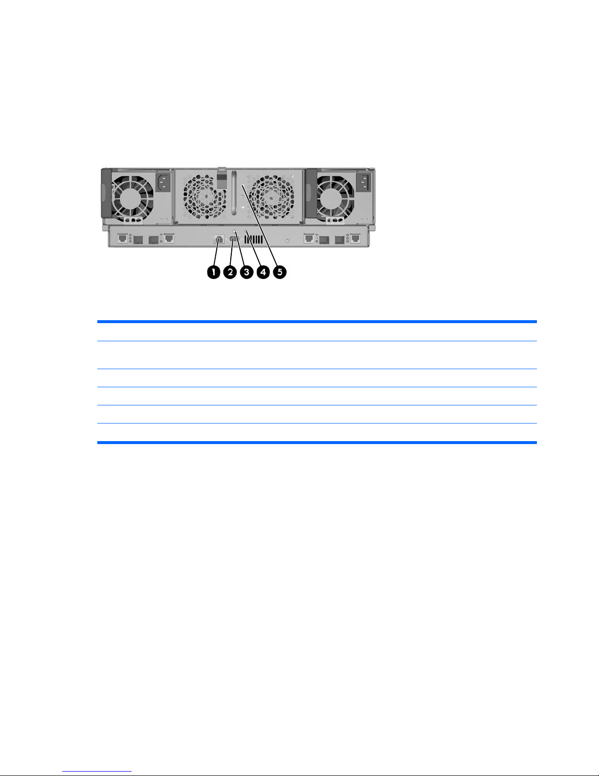
Identifying Integrated Administrator Components
Each HP PC Blade Enclosure interconnect tray ships with the Integrated Administrator module already
installed and provides external connectivity using two connectors on the rear panel.
Table 3-1 Integrated Administrator Rear Panel Components
Item Description
1 Management (10/100 Ethernet) connector for remote access through a Web-based user interface, Telnet,
or Secure Shell.
2 Console (serial) connector for local access to the command line interface using a laptop computer.
3 Integrated Administrator reset button.
4 Integrated Administrator health LED
5 Enclosure Unit Identification button/LED
Determining the Integrated Administrator’s Initial IP
Address
HP recommends that you connect a local client device, such as a laptop computer, to the console (serial)
connector in order to determine the initial IP address used by the network to recognize the Integrated
Administrator. After using that IP address to access the Integrated Administrator locally using the
console (serial) connector, you can use the Integrated Administrator default values to complete the initial
configuration.
The organization of this section reflects this process:
●
Requirements for local client devices
●
Default values for the Integrated Administrator
●
Determining the IP address using the local console
10 Chapter 3 Getting Started ENWW
Page 21

Requirements for Local Client Devices
You can access the Integrated Administrator locally using the serial connector on the rear panel of the
enclosure using a local client device, such as a laptop computer. The local client device must run a
terminal emulator, such as HyperTerminal for Windows systems or Kermit for Linux systems.
The terminal emulator must operate at the following settings:
●
Bits per second: 9600
●
Bits: 8
●
Parity: None
●
Stop bits: 1
●
Flow control: none
●
Emulation: VT100
●
Backspace key sends Ctrl-H
Default Values for the Integrated Administrator
The Integrated Administrator is configured with a default user name, password, and DNS name. A
settings tag with the preconfigured values is attached to the interconnect tray containing the Integrated
Administrator module. There is also a built-in administrator account for SOAP access, which is disabled
by default.
Username: SAM
Default Password: SamUser123
NOTE: This administrator account is disabled by default. You cannot login using this account
until you enable the SAM account.
It is important that the account password is changed from the default account password if the account
is enabled prior to normal usage by HP SAM. Lastly, the SOAP interface for all other accounts is disabled
by default, but is always enabled for the SAM account.
NOTE: For security reasons, HP recommends changing the Administrator password after accessing
Integrated Administrator for the first time.
ENWW Determining the Integrated Administrator’s Initial IP Address 11
Page 22

Determining the IP Address Using the Local Console
To determine the Integrated Administrator IP address using the local console perform the following
steps:
1. Access the Integrated Administrator console:
a. Connect a local client device (such as a laptop computer) with VT100 terminal emulation
software to the Integrated Administrator (serial) console connector using a null modem serial
cable.
b. Open a terminal emulation session with the following settings: 9600 bps, 8 data bits, no parity,
and 1 stop bit.
c. Log into the Integrated Administrator using the password on the settings tag attached to the
interconnect tray.
2. Establish the Integrated Administrator IP address.
For a detailed explanation of the command line conventions used in this document, see
Command
Line Conventions on page 121.
If a DHCP server is attached to the network, determine the Integrated Administrator IP address.
Type the following command at the command line interface:
SHOW NETWORK
If a DHCP server is not attached to the network, type the following commands sequentially to assign
a static IP address to the Integrated Administrator:
SET IPCONFIG STATIC <IP address><subnet mask>
SET GATEWAY <IP address>
SET DNS <primary address> {<secondary address>}
You can now access the Integrated Administrator using a Web browser, Secure Shell, Telnet, or
SNMP.
CAUTION: All settings are immediate and can only be manually restored.
12 Chapter 3 Getting Started ENWW
Page 23
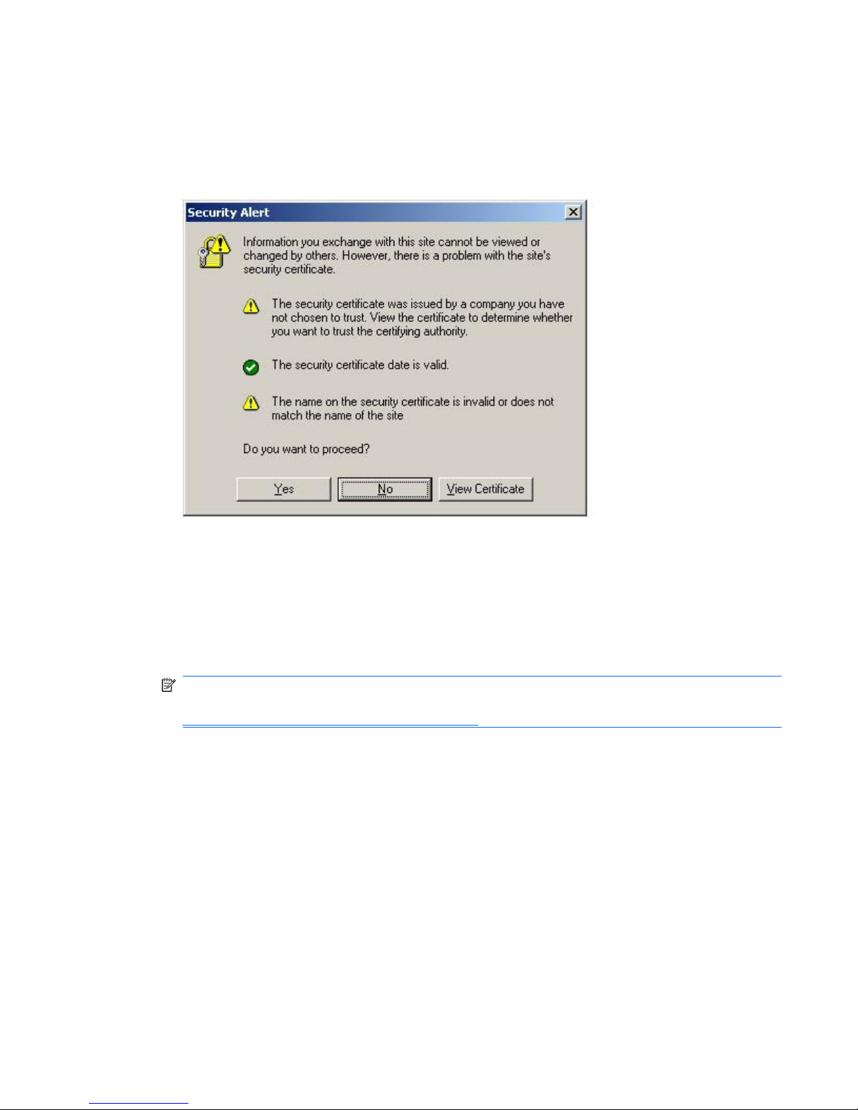
Setting Up the Web-Based User Interface
To set up the Web-based user interface, proceed as follows:
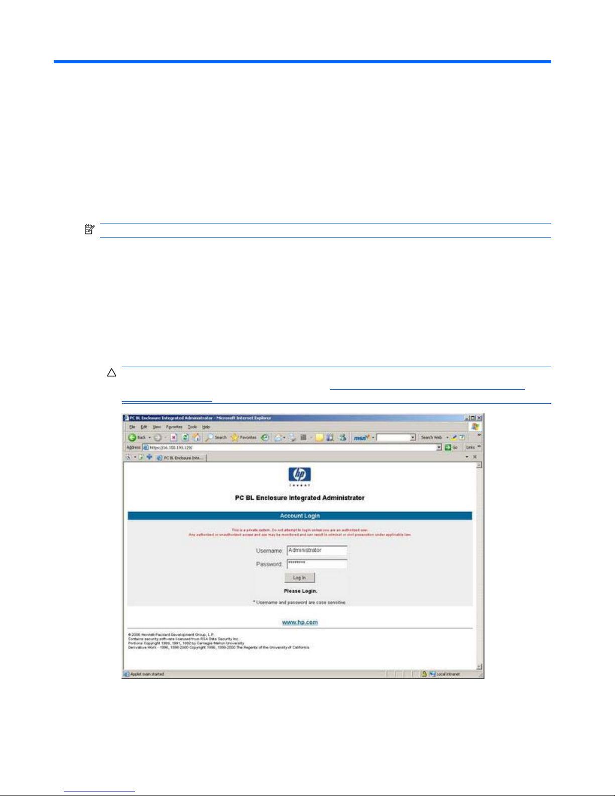
1. Type the Integrated Administrator IP address or DNS name in the address bar of the Web browser.
A security alert displays as shown below.
If you click Yes, the browser continues to the Login window of Integrated Administrator. The alert
message appears each time you access the Integrated Administrator management processor in a
browser.
If you click No, you are returned to what was previously displayed on your browser.
If you click View Certificate, a popup window displays the certificate information. Installing the
certificate to your browser prevents the security alert message from displaying in the future.
NOTE: To install your own certificate onto the Integrated Administrator rather than the
automatically generated certificate, see the information on certificate-related commands in
Administering Security Certificates on page 112.
If the certificate is removed from your browser, the security alert message is displayed again.
2. Install the certificate to your browser:
a. Click Install Certificate. The Certificate Manager Import Wizard starts.
b. Click Next.
c. Click Next for the browser to automatically select the certificate store when the Certificate
Store window appears.
d. Click Finish when the Completing the Certificate Manager Import Manager Wizard window
displays.
e. Click Yes to confirm the installation of the certificate when the confirmation window displays.
ENWW Setting Up the Web-Based User Interface 13
Page 24
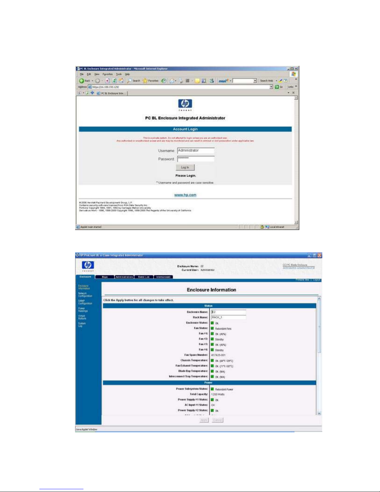
3. The Account Login screen (shown below) prompts you for a user name and password. Use the
default user name and password from the settings tag attached to the interconnect tray, and then
click Log In.
After the default user name and password have been verified, the summary window appears.
The Integrated Administrator summary window provides general information about the Integrated
Administrator, such as the user currently logged on, enclosure name and status, and Integrated
Administrator IP address and name.
14 Chapter 3 Getting Started ENWW
Page 25

Additional Steps
HP recommends performing the following tasks:
●
Change the Administrator password
●
Set the date and time
●
Name the enclosure and rack
●
Set up groups, users, and access privileges
For detailed instructions on performing these tasks, see the appropriate sections in
Setting Up the
System on page 71.
ENWW Additional Steps 15
Page 26
4 Web Browser Interface
This chapter provides information for navigating the Integrated Administrator Web-based user interface:
NOTE: Values appearing in the screens of this chapter are for illustrative purposes only.
Accessing the Web-based User Interface
Accessing the Web-based user interface is not supported from the console (serial) connector.
To access the Integrated Administrator Web-based user interface with HTTP:
1. Get the DNS name from the settings tag attached to the interconnect tray.
2. Open a Web browser and type the IP address or DNS name for the enclosure to access.
CAUTION: If your network does not provide DHCP and either Dynamic DNS or WINS services,
you need to configure a static IP address. See
Determining the IP Address Using the Local
Console on page 12.
3. Type the user name and password at the Login prompt.
16 Chapter 4 Web Browser Interface ENWW
Page 27
Web-Based Navigation
The Web-based user interface displays information and receives input in the following areas:
●
Top panel
●
Left panel
●
Deck panel
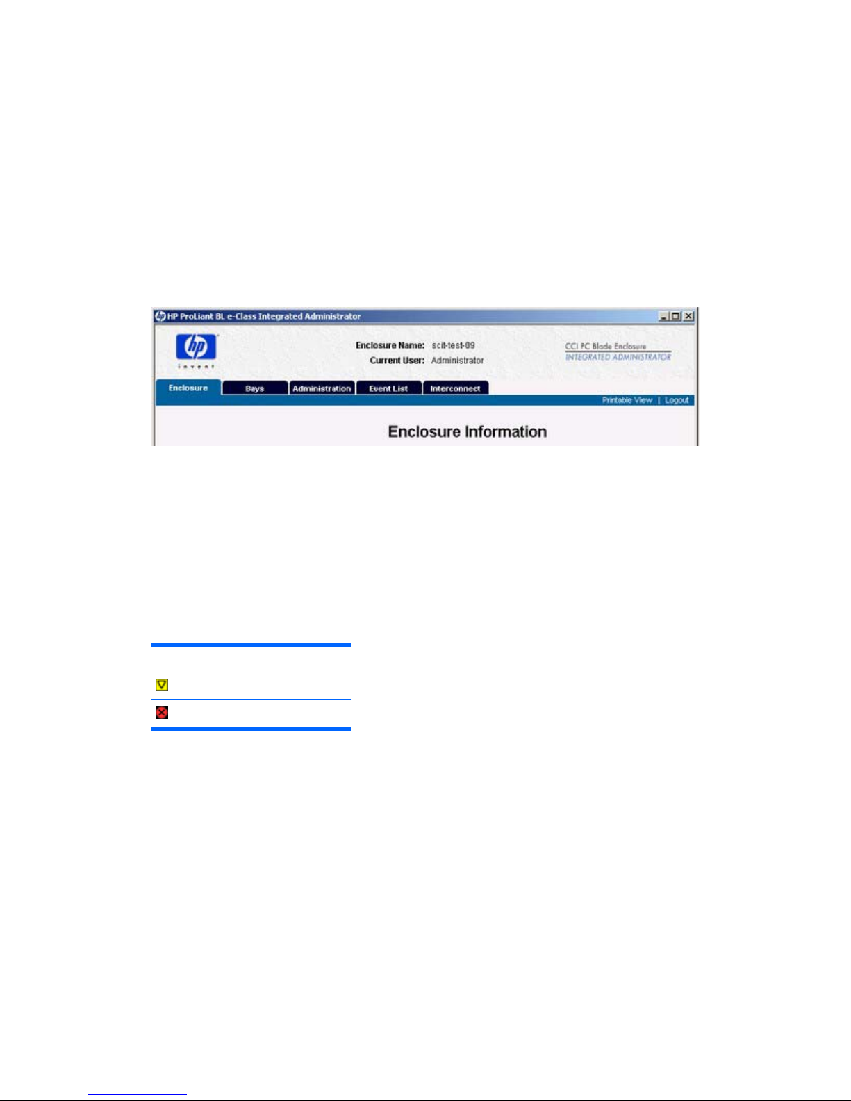
Top Panel
The following illustration shows the location of the top panel.
The top panel information is displayed at all times, including the following items:
●
Enclosure name
●
Current user
●
Tabs
The Integrated Administrator top panel provides real-time event notifications for an enclosure according
to two categories: caution and critical. When an event occurs, the Integrated Administrator notifies the
user by generating an icon that the user can click to view more details:
Icon Descripton
Caution
Critical
Two buttons appear on the top panel:
●
Printable View—Opens a separate window that shows information for cutting and pasting
purposes.
●
Log Out—Logs you out of the Web-based user interface.
Left Panel
The following illustration shows the location of the left panel.
ENWW Web-Based Navigation 17
Page 28
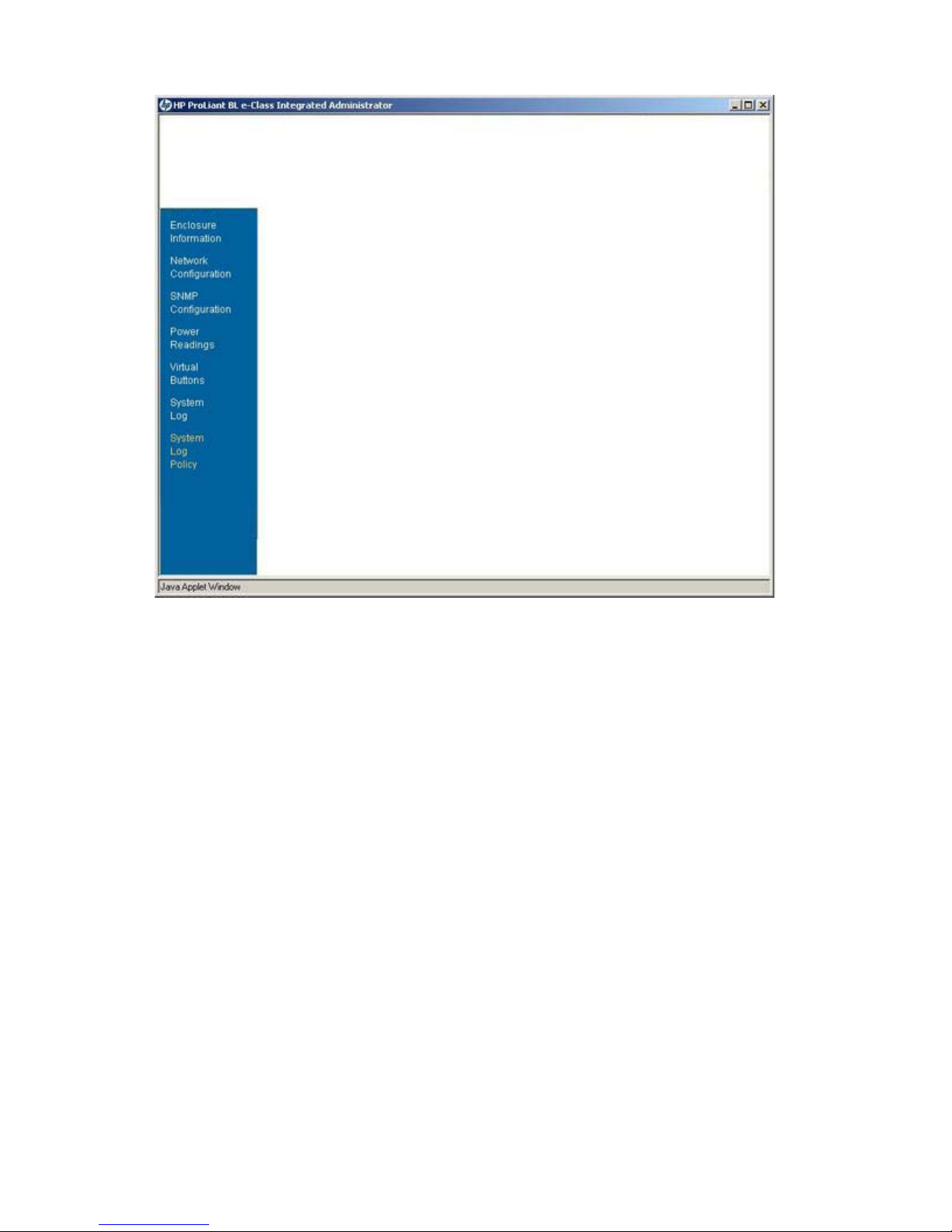
The left panel displays which screens are available under each tab. Information appearing in the left
panel depends on which tab the user chooses from within the top panel.
Deck Panel
The following illustration indicates the position of the deck panel.
18 Chapter 4 Web Browser Interface ENWW
Page 29
The deck panel displays the areas of information provided by the available screens under each tab.
Information appearing in the deck panel depends on the option chosen by the user from within the top
panel and the left panel.
Enclosure Tab
The Enclosure tab provides access to the following screens:
●
Enclosure Information
●
Network Configuration
●
SNMP Configuration
●
Power Readings
●
Virtual Buttons
●
System Log
●
System Log Policy
Enclosure Information
All users have read access to the information in this screen.
ENWW Enclosure Tab 19
Page 30
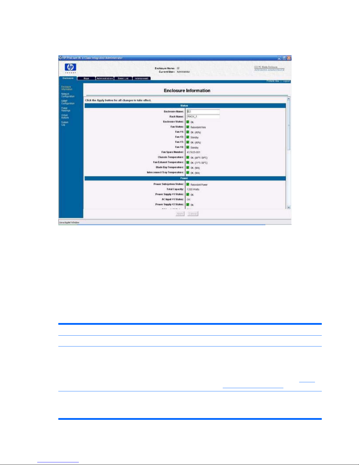
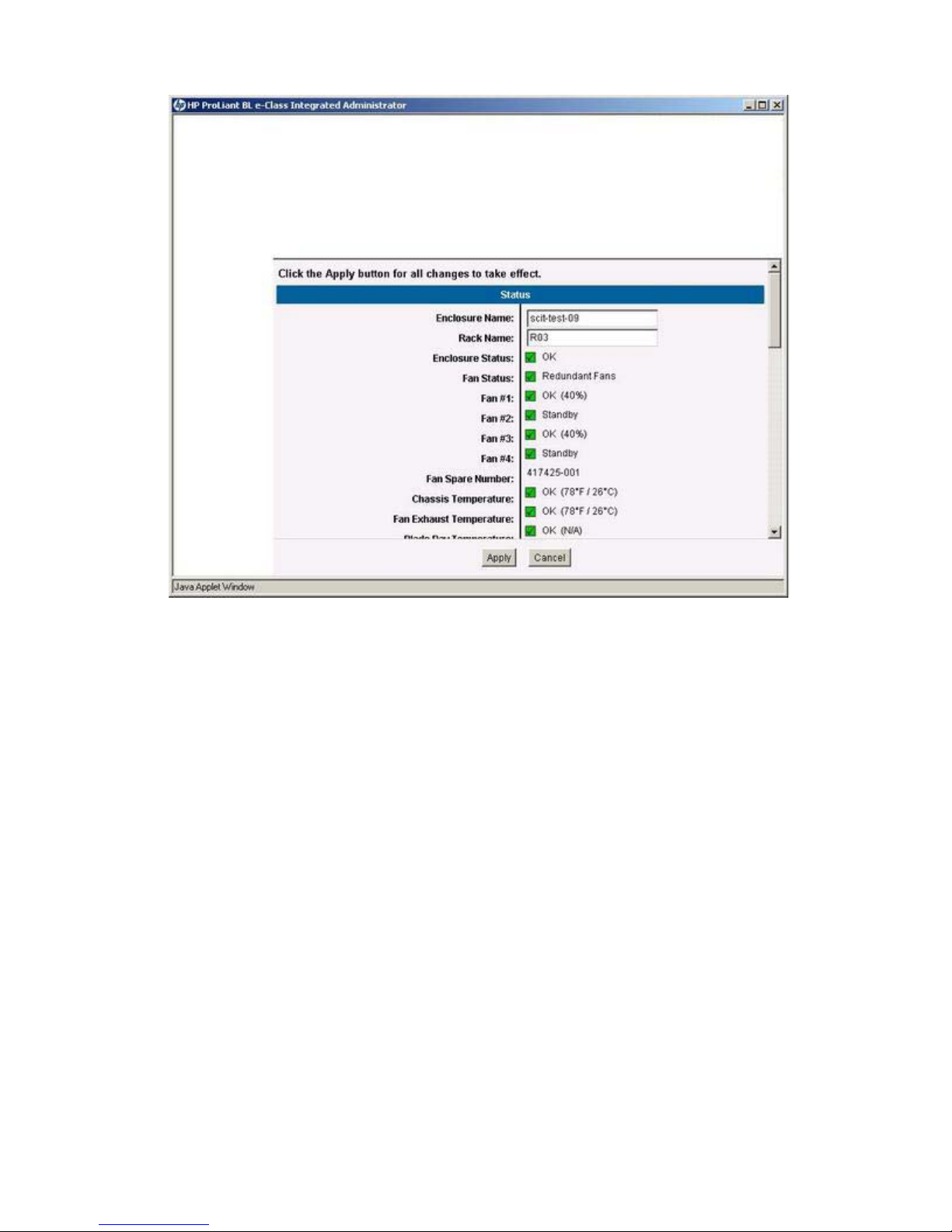
The following illustration shows the information presented on the Enclosure Information screen (status
area, one of six shown).
The Enclosure Information screen enables an enclosure administrator to update the rack name,
enclosure name, asset tag, time zone, date, and time, as well as observe the status and general
information for every component in the enclosure.
Two buttons appear on the Enclosure Information screen:
●
Apply—Saves changes made to the screen.
●
Cancel—Restores all fields on the screen to their original values.
The following table describes the information displayed in the areas that comprise the Enclosure
Information screen.
Table 4-1 Enclosure Information Field Descriptions—Status Area
Field Possible Values Description
Status Area
Enclosure Name
Maximum 32 characters including all
alphanumeric, dash, and underscore
characters.
Name of enclosure.
Only enclosure administrators have write
access to this field.
For the default enclosure name, see
Factory
Default Settings on page 138.
Rack Name Maximum 32 characters including all
alphanumeric, dash, and underscore
characters.
Name of rack.
Only enclosure administrators have write
access to this field.
20 Chapter 4 Web Browser Interface ENWW
Page 31

For the default rack name, see Factory Default
Settings on page 138.
Enclosure Status OK, Degraded, or Failed. Status of the enclosure.
Fan Status Redundant or non-redundant. Redundant: all fans are functional. Non-
redundant: at least one fan is not functional.
Fan #1—Fan #4 OK, Standby, Degraded, Failed, or Testing.
Percentage of full fan speed.
Status of fans 1 through 4.
Fan Spare Number The spare number for the fans installed in the
enclosure.
Temperature OK, Warm, Caution, or Critical. Enclosure component temperature sensor.
Table 4-2 Enclosure Information Field Descriptions—Power Area
Field Possible Values Description
Power Area
Power Subsystem Status
Redundant or Non-redundant. Redundant: both power supplies are
functional. Non-redundant: one power
supply is not functional.
Total Capacity Watts. Total capacity of the power supplies.
Power Supply #1 and #2 Status OK, Degraded, or Failed. Status of power supply #1 and power
supply #2.
AC Input #1 and #2 Status OK, Degraded, or Failed. Status of AC input to power supply #1
and AC input to power supply #2.
Power Supply Spare Number The spare number for the power supplies
installed in the enclosure.
Table 4-3 Enclosure Information Field Descriptions—General Area
Field Possible Values Description
General Area
Enclosure Type
Enclosure product type.
Part Number Part number for the enclosure.
Serial Number Serial number for the enclosure.
Asset Tag Maximum 31 characters including all
alphanumeric, dash, and underscore
characters
Asset tag
Only enclosure administrators have write
access to this field.
For the default asset tag value, see
Factory Default Settings on page 138.
Interconnect Tray Type HP PC Blade Enclosure Interconnect
Switch
HP PC Blade Enclosure RJ-45
Interconnect Patch Panel
Type of interconnect tray.
Interconnect Tray Part Number Part number for the interconnect tray.
Table 4-1 Enclosure Information Field Descriptions—Status Area (continued)
ENWW Enclosure Tab 21
Page 32

Interconnect Tray Spare Number Spare number for the interconnect tray.
Interconnect Tray Serial Number Serial number for the interconnect tray.
Table 4-4 Enclosure Information Field Descriptions—Integrated Administrator Area
Field Possible Values Description
Integrated Administrator Area
Hardware Version
Hardware version of the Integrated
Administrator of the enclosure.
Software Version Software version of the Integrated
Administrator of the enclosure.
Additionally, build version is displayed.
Table 4-5 Enclosure Information Field Descriptions—Network Area
Field Possible Values Description
Network Area
IP Address
###.###.###.###, where ### ranges
from 0 to 255.
The IP address of the Integrated
Administrator.
DHCP Enabled or Disabled. Shows the status of the Dynamic DNS
This field appears only if DHCP is
enabled.
MAC Address ##:##:##:##:##:## where ## ranges from
00 to FF.
The MAC address of the Integrated
Administrator.
Table 4-6 Enclosure Information Field Descriptions—Date and Time Area
Field Possible Values Description
Date and Time Area
Time Zone
Drop-down box with standard time zones
listed
Time zone assigned to the enclosure
For the default time zone, see
Factory
Default Settings on page 138.
For a list of all supported time zones,
see
Time Zone Settings on page 141.
For a detailed description of how to set
the time zone of the enclosure to a value
not listed in the drop down box, select
Other.
For additional information, see
Troubleshooting on page 134.
Date mm/dd/yy The date assigned to the enclosure
Time hh:mm (24-hour format) The time assigned to the enclosure
Table 4-3 Enclosure Information Field Descriptions—General Area (continued)
22 Chapter 4 Web Browser Interface ENWW
Page 33

Only enclosure administrators have access to the Date and Time information. If those fields are not
being modified, the Integrated Administrator updates these fields every 20 seconds. If automatic time
configuration is enabled, the date and time fields are grayed out and cannot be modified.
If you select Other for time zone, use the following window to set a user-defined time zone:
Three buttons appear on this window:
●
Apply—Applies the new time zone.
●
Reset—Clears the time zone text box.
●
Cancel—Cancels all changes and closes the window.
For more information on accepted time zones, refer to
Time Zone Settings on page 141.
Network Configuration
NOTE: Only enclosure administrators have access to these settings.
The Network Configuration screen (shown below) enables the enclosure administrator to modify the
network settings of an enclosure. These settings are specific to the enclosure and do not affect the
network configurations for blade PCs.
ENWW Enclosure Tab 23
Page 34

Two buttons appear at the bottom of this screen:
●
Apply—Saves changes made to the screen.
●
Cancel—Restores all fields on the screen to their original values.
CAUTION: Both the Web and Secure Shell protocols must be enabled to allow access to the Web-
based user interface.
The following table describes the information displayed in the areas that comprise the Network
Configuration screen.
Table 4-7 Network Configuration Field Descriptions—Information Area
Field Possible Values Description
Information Area
IP Address
The IP address of the Integrated
Administrator.
MAC Address The MAC address of the Integrated
Administrator.
Table 4-8 Network Configuration Field Descriptions—Protocols Area
Field Possible Values Description
Protocols Area
Web (HTTP/HTTPS)
Enabled or Disabled. The default setting is Enabled.
24 Chapter 4 Web Browser Interface ENWW
Page 35

SNMP Enabled or Disabled. The default setting is Enabled.
Secure Shell Enabled or Disabled. The default setting is Enabled.
Telnet Enabled or Disabled. The default setting is Enabled.
SOAP Enabled or Disabled. The default setting is Disabled.
Table 4-9 Network Configuration Field Descriptions—Network Area
Field Possible Values Description
Network Area
DHCP
Gets the IP address of the Integrated
Administrator from the DHCP.
Static IP Sets a static IP address of the Integrated
Administrator.
Dynamic DNS Determines whether the Integrated
Administrator uses Dynamic DNS.
IP Address ###.###.###.###, where ### ranges
from 0 to 255.
Static IP address for the Integrated
Administrator (mandatory if Static IP is
selected).
Subnet Mask ###.###.###.###, where ### ranges
from 0 to 255.
Subnet mask for the Integrated
Administrator (mandatory if Static IP is
selected).
Gateway Address ###.###.###.###, where ### ranges
from 0 to 255.
Gateway address for the Integrated
Administrator (optional field if Static IP is
selected).
DNS Server 1 ###.###.###.###, where ### ranges
from 0 to 255.
The IP address for the primary DNS
server (optional field if Static IP is
selected).
DNS Server 2 ###.###.###.###, where ### ranges
from 0 to 255.
The IP address for the secondary DNS
server (optional field if Static IP is
selected).
SNMP Configuration
The SNMP Configuration screen (shown below) enables an enclosure administrator to modify the SNMP
settings of an enclosure. These settings are specific to the enclosure and do not affect the network
configurations for blade PCs.
Two buttons appear at the bottom of this screen:
●
Apply—Saves changes made to the screen.
●
Cancel—Restores all fields on the screen to their original values.
Table 4-8 Network Configuration Field Descriptions—Protocols Area (continued)
ENWW Enclosure Tab 25
Page 36

The following table describes the information presented on the SNMP Configuration screen:
Table 4-10 SNMP Configuration Field Descriptions—System Information Area
Field Possible Values Description
System Information Area
SNMP Status
Enabled or Disabled Displays if SNMP is enabled or disabled.
System Name The name of the enclosure.
System Location Up to 20 characters including all
alphanumeric, dash, underscore, and
space characters
The SNMP location of the enclosure
For the default SNMP contact, see
Factory Default Settings on page 138.
System Contact Up to 20 characters including all
alphanumeric, dash, underscore, and
space characters
The SNMP contact of the enclosure
For the default SNMP contact, see
Factory Default Settings on page 138.
Table 4-11 SNMP Configuration Field Descriptions—Community Strings and Trap Destinations Area
Field Possible Values Description
Community Strings and Trap Destinations Area
Read Community
Up to 20 characters including all
alphanumeric, dash, underscore, and
space characters
Displays the SNMP read community
string
If this is left blank, “public” is assigned.
26 Chapter 4 Web Browser Interface ENWW
Page 37

For the default read Community string,
see
Factory Default Settings
on page 138.
Write Community Up to 20 characters including all
alphanumeric, dash, underscore, and
space characters
Sets the SNMP write community string
If this is left blank, SNMP SET
commands are disabled.
For the default write Community string,
see Factory Default Settings
on page 138.
Add Adds an IP address to the list of trap
destinations.
Remove Removes the selected IP addresses
from the list of trap destinations.
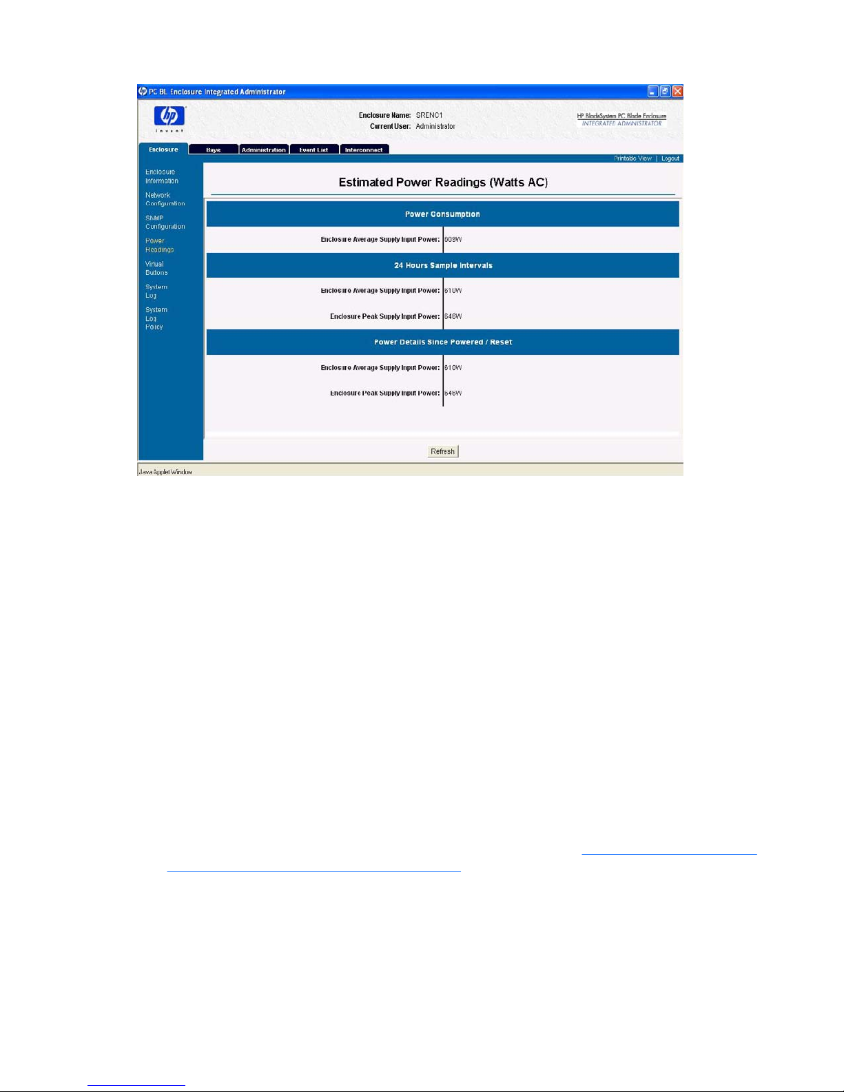
Power Readings
The Power Readings screen provides power consumption estimates for the enclosure. This screen
includes the following fields:
NOTE: Power readings are shown only if the enclosure has a non-power-aware blade present. This
is a feature of HP BladeSystem bc2x00 Blade PCs only.
The screen may differ from the image shown here.
Table 4-11 SNMP Configuration Field Descriptions—Community Strings and Trap Destinations Area
(continued)
ENWW Enclosure Tab 27
Page 38

●
Enclosure Average Supply Input Power—The immediate average power consumption averaged
over the last 5 second sample interval.
●
Enclosure Average Supply Input Power 24-Hour Sample Intervals—This is a rolling average
of power consumption over the course of preceding last 24 hours of uptime.
●
Enclosure Peak Supply Input Power 24-Hour Sample Intervals—This is the peak of power
consumption over the course of the preceding 24 hours of uptime.
●
Enclosure Average Supply Input Power Time Averaged Since Powered—This is the power
consumption averaged over the total uptime for the IA. This is since the previous power cycle or
IA reset.
●
Enclosure Peak Supply Input Power Time Averaged Since Powered—This is the peak of power
consumption over the total uptime for the IA. This is since the previous power cycle or IA reset.
NOTE: All statistics are calculated from the time of the last reboot, up to 24-Hours.
Virtual Buttons
NOTE: Only enclosure administrators can execute these commands.
The Virtual Buttons screen (shown below) enables an enclosure administrator to modify the power state
of the enclosure and Unit Identification LED from a remote location to facilitate troubleshooting by
technicians in the data center.
28 Chapter 4 Web Browser Interface ENWW
Page 39

The Toggle On/Toggle Off button remotely changes the state of the enclosure Unit Identification LED.
The illustration below shows the information presented in the Enclosure Power area of the Virtual
Buttons screen:
You can select the appropriate function with the following buttons:
●
Restart Integrated Administrator—Restarts the Integrated Administrator and does not affect the
blade PCs.
●
Power Off Enclosure—Attempts a graceful shutdown of the system for 5 minutes, after which time
this command powers down all components of the enclosure immediately.
CAUTION: HP recommends that you use the operating system shutdown procedures before
powering down a blade PC or enclosure. After the enclosure is powered off, powering on can only
occur by local access to the system.
System Log
The System Log screen (shown below) provides an enclosure administrator with a chronological list of
events and updates associated with the enclosure.
Two buttons appear at the bottom of this screen:
●
Refresh—Refreshes the screen.
●
Clear—Clears the system log.
ENWW Enclosure Tab 29
Page 40

System Log Policy
The System Log Policy screen (shown below) provides an enclosure administrator with display and
control over the logging of some system logged event messages.
There are two radio buttons for each event severity classification corresponding to enclosure and bay
system log policies:
●
Critical—ON / OFF
NOTE: Enclosure and bay critical syslog messages cannot be masked.
●
Major—ON / OFF
●
Minor—ON / OFF
●
Normal—ON / OFF
●
Informational—ON / OFF
All enclosure and bay system log policies are defaulted to ON.
For details concerning specific system log messages, see
Error Messages on page 122 for supported
system log messages and severity classification.
30 Chapter 4 Web Browser Interface ENWW
Page 41

Bays Tab
The Bays tab provides access to the following screens:
●
Bay List
●
Bay Information
●
Remote Console
●
Virtual Buttons
●
Console Log
●
Bay Power Consumption
Bay List
The Bay List screen (shown below) enables an enclosure administrator to observe and update the
assignment of groups to blade PC bays, as well as monitor the status of each blade PC installed in the
enclosure.
Group administrators and group members with permissions can view the blade PC bays assigned to
their groups.
The following table describes the information presented in the Bay List screen:
ENWW Bays Tab 31
Page 42

Table 4-12 Bay List Field Descriptions
Field Possible Values Description
Bay # 1-20 Blade PC number.
UID Displays a blue circle if the unit
identification (UID) LED of the blade is lit.
Blade PC Name Name of the blade PC in that blade PC
bay as defined by the operating system
of the blade PC.
NOTE: The blade PC health service
must be installed for the Integrated
Administrator to obtain the blade PC
name and operating system type.
Assigned to Group Name of the group that owns that bay.
Status OK, Degraded, or Failed The status and power state of the blade
PC.
The following table lists permissions that are related to the action buttons of the Bay List screen
Table 4-13 Bay List Action Buttons and Permissions
Field Possible Values Description
View/Modify Opens the Blade Information screen. Enclosure administrators, group
administrators, and group members with
permissions.
Remote Console Opens the Remote Console screen. Enclosure administrators, and group
administrators with permissions.
Console Log Opens the Console Log screen. Enclosure administrators, group
administrators, and group members with
permissions.
View Group Opens the View/Modify Group screen. Enclosure administrators only.
Bay Assignment Opens the Bay Assignment dialog box.
NOTE: If a blade PC is to be re-
assigned, it must be unassigned first.
Enclosure administrators only.
Bay Information
NOTE: Be sure the Integrated Administrator displays up-to-date blade PC information by rebooting
the blade PC after installing the blade PC health service. The blade PC may need to be rebooted a
second time to fully update the Integrated Administrator.
The Bay Information screen (shown below) enables an enclosure administrator to observe the status
and general information for a blade PC in a given blade PC bay. Group administrators and group
members with View rights to the blade PC bay can also observe this information.
32 Chapter 4 Web Browser Interface ENWW
Page 43

To be sure that the Bay Information screen displays the optimal number of possible values, you must
have the blade PC health driver installed.
The following table describes the information presented on the Bay Information screen for all enclosure
administrators and for group members and groups with rights to the blade PC bay.
Table 4-14 Bay Information Field Descriptions—Status Area
Field Possible Values Description
Status Area
Bay Number
Bay number.
Blade PC Name Name of blade PC as specified with the
blade PC operating system.
Status OK, Degraded, or Failed Status of the blade PC.
NOTE: In the case of a failed or
degraded BC2x00 blade, an additional
diagnostic message is posted in
parentheses.
ENWW Bays Tab 33
Page 44

Thermal Condition OK, Warm, Caution, or Critical Thermal condition of the blade.
NOTE: In the case of a thermal critical
or caution condition, BC2x00 blades
provide thermal measurements for the
CPU, Graphics processor, and ambient
sensors in degrees Celsius at the time of
failure detection.
Enclosure Name Name of enclosure.
For the default enclosure name, see
Factory Default Settings on page 138.
Table 4-15 Bay Information Field Descriptions—General Area
Field Possible Values Description
General Area
Blade PC Type
Product name of the blade PC.
Blade PC Installed OS Operating system installed on the blade
PC.
Spare Number Spare number of the blade PC.
Serial Number Serial number of the blade PC.
Asset Tag Asset tag number of the blade PC.
BIOS Version mm/dd/yy ROM version on the blade PC.
CPU # Type Type of processor on the blade PC.
CPU # Max Speed Speed associated with the blade PC
processor.
Installed RAM Amount of memory installed on the blade
PC.
NIC #1 and #2 MAC Addresses ##:##:##:##:##:##, where ## ranges
from 00 to FF.
MAC address of the NIC 1 interface and
the NIC 2 interface.
BMC Revision 00 to FF BMC Revision: For BC2x00 blades, the
Blade Management Controller (BMC)
revision will be posted here. The BMC
versions prior to version 23 do not report
this value. N/A will be shown in
parentheses. Future versions of the BMC
will provide this information.
Remote Console
Enclosure administrators and group administrators with access to the bay can click Remote Console
to open a remote text-based console (shown below) to the blade PC in the bay.
NOTE: Click on the command windows to assure it has focus, otherwise no commands can be entered.
Table 4-14 Bay Information Field Descriptions—Status Area (continued)
34 Chapter 4 Web Browser Interface ENWW
Page 45

For information on establishing remote console connectivity, see Enabling Remote Console Sessions
to Blade PCs on page 82.
Virtual Buttons
Enclosure administrators and group administrators with permissions can use the Virtual Buttons screen
(shown below) to modify the state of the power state and Unit Identification LED of a blade PC in order
to facilitate troubleshooting from a remote location.
ENWW Bays Tab 35
Page 46

The Virtual Buttons screen enables group administrators and enclosure administrators to reboot, power
off, or identify the blade PC with the following items:
●
The Toggle On/Off button remotely changes the state of the blade PC Unit Identification LED.
●
You can select the appropriate function in the Blade PC Power area using the following radio
buttons:
◦
Reboot reboots the blade PC.
◦
Power Off attempts a graceful shutdown of the blade PC for 5 minutes, after which time this
command powers down the blade PC immediately. This is the equivalent to a less than 3second power button press on a standard desktop PC.
◦
Power Off Immediately powers off the blade PC forcefully. This is the equivalent to a 5second power button press on a standard desktop PC.
CAUTION: Without service, an ACPI-compliant operating system, the Integrated Administrator cannot
gracefully shut down a blade PC. This condition can result in the permanent loss of data.
NOTE: Click Apply for these settings to take effect.
Whenever possible, HP recommends that you use the operating system shutdown procedures before
powering down a blade PC or enclosure. Once the enclosure is powered off, powering on can only occur
with local access to the system.
36 Chapter 4 Web Browser Interface ENWW
Page 47

Console Log
NOTE: Only group members, group administrators, and enclosure administrators can view a console
log of a blade PC.
The Console Log screen displays the console log for the specified bay. The console log of the bay is
not stored between reboots of the Integrated Administrator, so the information will only include what has
taken place since the last power on of the Integrated Administrator.
The data captured in the console log is all output from the serial console of the blade PC that occurred
while no one was connected to the console. For security reasons, console output during a user
connection session is not logged.
The Refresh button refreshes the console log for the current blade PC.
Bay Power Consumption
The Bay Power Consumption screen (shown below) enables an enclosure administrator to observe the
power consumption of all populated bays within the enclosure.
The table reports the following information:
●
Bay #
●
Bay Type—This is necessary to know this since only BC2x00 blades are power-aware and report
power to the IA.
●
Wdc—This is direct current (DC) power consumption in Watts of the blade averaged over the last
1 second sampling interval.
ENWW Bays Tab 37
Page 48

●
Wdc (24hr Avg.)—This is direct current (DC) power consumption in Watts of the blade averaged
over the last 24 hours of operation within the enclosure.
●
Wdc (Overall Avg.)—This is direct current (DC) power consumption in Watts of the blade averaged
over the last 24 hours of operation within the enclosure.
NOTE: Power reporting is a feature limited to BC2x00 series of blades. All others will not report a value
in the any of wattage columns.
All statistics are calculated from the time of the last reboot, up to 24-Hours.
38 Chapter 4 Web Browser Interface ENWW
Page 49

Administration Tab
For an explanation of user rights associated with the Integrated Administrator, see Enabling Remote
Console Sessions to Blade PCs on page 82.
The Administration tab provides access to the following screens:
●
User List
●
Group List
●
Add User
●
Add Group
●
View/Modify User
●
View/Modify Group
User List
The User List screen (shown below) enables an appropriate group administrator or enclosure
administrator to observe and update user access to groups and blade PC bays.
The following table lists the permissions related to the action buttons of the User List screen.
Table 4-16 User List Action Buttons and Permissions
Button Function Permissions
View/Modify User Opens the View/Modify User screen. Enclosure administrators can access
and modify the information for any user.
Users can access and modify the
information for own account.
Remove User Removes the selected user (unless the
account is your own).
Only enclosure administrators can
execute this command.
The following table describes the information presented in the User List screen.
Table 4-17 User List Field Descriptions
Button Function Permissions
ENWW Administration Tab 39
Page 50

User Name User login name.
Full Name User full name.
Account Type Administrator or User Shows if the user is an enclosure
administrator.
Account Status Enabled or Disabled Shows if the user’s account is enabled.
Group Membership Shows the groups in which the user has
membership.
Group List
The Group List screen (shown below) enables an enclosure administrator to observe and update the
assignment of groups and users to blade PC bays.
Two buttons appear on this screen:
●
View/Modify Group—Opens the View/Modify Group screen.
●
Remove Group—Removes the selected group.
NOTE: Enclosure administrators can view and modify the information for all groups. Group
administrators and group members can view the information for the groups in which they are members.
Table 4-18 Group List Field Descriptions
Field Description
Group Name Group name
Table 4-17 User List Field Descriptions (continued)
40 Chapter 4 Web Browser Interface ENWW
Page 51

Assigned Bays Blade PC bays that the group owns
Group Members Users with membership in the group
Add User
NOTE: Only enclosure administrators have access to this area of the Integrated Administrator.
The Add User screen (shown below) enables an enclosure administrator to create a user profile,
including group and blade PC bays assignments.
Two buttons appear on this screen:
●
Apply—Saves changes made to this screen.
●
Cancel—Restores all fields on this screen to their original values.
The following table describes the fields /of the Add User screen.
Table 4-19 Add User Field Descriptions
Field Possible Values Description
User Name 1-13 characters including alphanumeric,
dash, and underscore characters.
Login name of the user.
Table 4-18 Group List Field Descriptions (continued)
ENWW Administration Tab 41
Page 52

The user name must begin with a letter.
A maximum of 25 users can be created
in addition to the reserve accounts.
NOTE: “Administrator,” switch,”
switcha, ”switchb,” “SAM,” and “all” are
reserved names and cannot be used.
This restriction is not case-sensitive.
Password 3-8 characters including all printable
characters
User’s password.
Confirm Password 3-8 characters including all printable
characters
User’s password.
Account Type Radio buttons (Administrator and User) Determines if the user has enclosure
administrator rights.
Account Status Radio buttons (Enabled and Disabled) Determines if the user’s account is
enabled.
Full Name (optional) 1-20 characters
Accepts only alphanumeric, dash,
underscore, and space characters
Full name of user.
Contact Information (optional) 1-20 characters
Accepts only alphanumeric, dash,
underscore, and space characters
Optional user contact information.
Group Names All groups are listed A list of all possible groups.
Group Membership x number of groups (all groups in which
the user has membership)
A list of all groups of which the user is a
member.
Add User [View]>>> Adds the user to the selected groups in
the Group Names text box with View
rights for group members
These groups appear in the Group
Membership text box. The user loses
View/Modify rights if they previously had
them.
Add User [View/Modify]>>> Adds the user to the selected groups in
the Group Names text box with View/
Modify rights for group administrators or
view rights for group members.
<<< Removes the user from the selected
groups in the Group Membership text
box.
Add Group
NOTE: Only enclosure administrators have access to this area of the Integrated Administrator.
The Add Group screen (shown below) enables an enclosure administrator to create a group profile,
including user and blade PC bays assignments.
Table 4-19 Add User Field Descriptions (continued)
42 Chapter 4 Web Browser Interface ENWW
Page 53

NOTE: Grayed-out check boxes are unavailable because they are already assigned to another group.
Two buttons appear on this screen:
●
Apply—Saves changes made to this screen.
●
Cancel—Restores all fields on this screen to their original values.
Table 4-20 Add Group Field Descriptions—Group Information Area
Field Possible Values Description
Group Information Area
Group Name
1-13 characters including alphanumeric,
dash, and underscore characters.
The group name must begin with a letter.
A maximum of 20 users can be created.
Name of group.
Group Description (optional) 1-20 characters
Accepts only alphanumeric, dash, and
underscore characters.
Description of group.
Table 4-21 Add Group Field Descriptions—Bay Assignment Area
Field Possible Values Description
Bay Assignment Area
ENWW Administration Tab 43
Page 54

Bay 1 - Bay 20 Determines which bays the group owns.
Only one group can own a particular bay.
If a check box is disabled, another group
already owns the bay.
Select All Selects all check boxes of the bays.
Clear All Clears all check boxes of the bays.
Table 4-22 Add Group Field Descriptions—Group Membership Area
Field Possible Values Description
Group Membership Area
User Names
All users and enclosure administrators
are listed.
A list of all possible users.
Group Members x number of users (all users that are
members of the group).
A list of all users that are members of the
group.
Add User [View]>>> Adds selected users in the User Names
text box to the group with View rights for
group members.
Users lose View/Modify rights for group
administrators if they previously had
them.
Add User [View/Modify]>>> Adds selected users in the User Names
text box to the group with View/Modify
rights for group administrators.
<<<Remove User Removes selected users in the Group
Members text box from the group.
View/Modify User
You can access the View/Modify User screen by clicking any row in the User List and then clicking View/
Modify User. The View/Modify User screen provides the same functions and has the same access as
the Add User screen. See the “Add User” section in this chapter.
View/Modify Group
You can access the View/Modify Group screen by clicking any row in the Group List and then clicking
View/Modify Group. The View/Modify Group screen the provides same functions and has the same
access as the Add Group screen. See
Add Group on page 42 in this chapter.
Table 4-21 Add Group Field Descriptions—Bay Assignment Area (continued)
44 Chapter 4 Web Browser Interface ENWW
Page 55

Event List Tab
The Event List tab provides access to the following screens:
●
Event List
●
Event Log Policy
The Event List differs from the System Log in the following ways:
●
Any user can view the Event List. Only enclosure administrators can access the System Log.
●
The messages in the Event List are limited to cautions and critical failures. Refer to the enclosure
System Log for information on both failures and fixes.
●
The Event List only displays messages received since the user logged into the Integrated
Administrator. The System Log displays every message generated by the enclosure diagnostics.
The Event List screen (shown below) provides the following information for each event:
●
Severity
●
Source
●
Date
●
Time
●
Event Details (the example below indicates a fan failure)
The Integrated Administrator provides real-time event notifications for an enclosure according to two
categories of severity (caution and critical) described in the following table. For detailed information
ENWW Event List Tab 45
Page 56

regarding the Event List, including a comprehensive list of event messages, see Event Icons and
Details on page 136.
Table 4-23 Event Notification Icons
Icon Description
Caution—An event that does not prevent the enclosure from operating, maintaining power, or serving its
user community
When a caution event occurs, a reasonable guarantee that operability can persist no longer exists.
Critical—An event that prevents the continued operation of the enclosure.
When a critical event occurs, the inoperability of the enclosure is imminent.
Event Log Policy
●
Critical—ON / OFF
●
Major—ON / OFF
●
Minor—ON / OFF
●
Normal—ON / OFF
●
Informational—ON / OFF
The default is ON for all Enclosure event log policies. The default is ON for all Bay event log policies
except Normal and Informational.
46 Chapter 4 Web Browser Interface ENWW
Page 57

For details concerning specific event log messages, see Error Messages on page 122 for supported
event log messages and severity classification.
Interconnect Tab
The Interconnect Tray screen (shown below) allows anyone to view information about the interconnect
tray. It allows enclosure administrators to connect to the remote console of one of the interconnect
switches if installed.
The following table describes the information displayed in the areas that comprise the Interconnect Tray
screen.
Table 4-24 Interconnect Tray Screen Field Descriptions—Interconnect Tray Information Area
Field Possible Values Description
Interconnect Tray Information Area
Status
OK, Degraded, or Failed Status of the interconnect tray.
Temperature OK, Warm, Caution, or Critical Thermal status of the interconnect tray.
Switch A Status OK, Degraded, or Failed Status of Switch A. This will only be
displayed if an interconnect switch is
installed.
Switch B Status* OK, Degraded, or Failed Status of Switch B. This will only be
displayed if an interconnect switch is
installed.
ENWW Interconnect Tab 47
Page 58

Manufacturer Manufacturer of the interconnect tray.
Product Name Product name of the interconnect tray.
Interconnect Tray Part Number Spare part number of the interconnect
tray.
Interconnect Tray Serial Number Serial number of the interconnect tray.
* Proliant C-GbE e-Class switch only.
Table 4-25 Interconnect Tray Screen Field—Switch Terminal Console Area (only present if an interconnect
switch is installed)
Field Possible Values Description
Switch Terminal Console Area (only present if an interconnect switch is installed)
Switch A button
Opens a new window to the remote
console of switch A.
Switch B button* Opens a new window to the remote
console of switch B.
* Proliant C-GbE e-Class switch only.
Table 4-24 Interconnect Tray Screen Field Descriptions—Interconnect Tray Information Area (continued)
48 Chapter 4 Web Browser Interface ENWW
Page 59

5 Command Line Interface
This chapter provides reference material for operating the Integrated Administrator Command Line
Interface (CLI). This chapter provides command line related information with the following sections:
●
Accessing the Command Line Interface
●
Operating the Command Line Interface
◦
General commands
◦
General management commands
◦
User account commands
◦
Enclosure network configuration commands
◦
Enclosure management commands
◦
Blade PC management commands
●
Functionality exclusive to the command line interface
For a detailed explanation of the command line conventions used in this document, see
Command
Line Conventions on page 121.
For easy reference, the index of this book also provides a comprehensive listing of the commands
supported by the Integrated Administrator.
ENWW 49
Page 60

Accessing the Command Line Interface
You can access the CLI remotely through the management (10/100 Ethernet) connector, locally through
the console (serial) connector on the rear panel of the enclosure, or through any uplink depending on
VLAN configuration.
Accessing Remotely through the Management Connector
To access the Integrated Administrator command line interface remotely through the management
(10/100 Ethernet) connector:
1. Get the default host name from the settings tag attached to the interconnect tray.
2. Open a Telnet or Secure Shell application and type the IP address or DNS name for the enclosure
you wish to access.
CAUTION: Using Telnet instead of Secure Shell means your remote session, including
password, appears in clear text on that network.
3. Type the user name and password into the Login prompt.
Accessing Locally through the Console Connector
To access the Integrated Administrator locally through the serial connector:
1. Connect a local client device, such as a laptop computer, to the serial connector using a null-modem
cable.
NOTE: Client devices must satisfy the requirements provided in Requirements for Local Client
Devices on page 11.
2. Open the terminal emulator and press Enter one or more times to get the login prompt.
3. Type the user name and password.
50 Chapter 5 Command Line Interface ENWW
Page 61

Operating the Command Line Interface
General Commands
The following table describes the information displayed in the areas that comprise the Enclosure
Information screen.
Table 5-1 General Commands
Command Description Restrictions
CLEAR SCREEN Clears the terminal screen None
EXIT Exits the command line interpreter None
HELP {<ommand>} |Tree If a command is given, the usage and help text for the
command are shown in a tree format. If no argument is given,
all base commands are displayed.
None
LOGOUT Exits the command line interpreter None
QUIT Exits the command line interpreter
SLEEP Pauses the sessions for a fixed period of time. Useful for
adding delays to scripts. The <seconds> field can be any whole
number from 1 - to 86400. Once the pause has started, no way
exists to continue the session before time runs out, but you can
terminate the session and start another one.
None
General Management Commands
The following table describes the information displayed in the areas that comprise the Enclosure
Information screen.
Table 5-2 General Management Commands
Command Description Restrictions
CLEAR SSESSION SWITCH
[A | B]
Terminate a Terminal session from the enclosure.
This is not a graceful termination. The connected user loses
any unsaved work.
Group administrators may only
execute thus command for the
blade PC bays to which they
have access.
CLEAR SSHKEY Remove the contents of the Secure Shell authorized keys file.
After performing this command, you will not be able to login
using the public key-based authentication.
Only enclosure administrators
may execute this command.
CONNECT SWITCH [A | B] Opens a remote console connection to switch A or B.
A single switch cannot support multiple, simultaneous remote
console sessions.
Only enclosure administrators
may execute this command.
DOWNLOAD CERTIFICATE
<url>
Download a CA supplied PKCS#7 file to replace the current
security certificate on the system.
Supported protocols are http, ftp, and tftp. Format the URL as
protocol://host/path/file.
If your ftp server does not support anonymous connections,
you can specify a username and password by augmenting the
host part in the above format with username:password@host.
Only enclosure administrators
may execute this command.
ENWW Operating the Command Line Interface 51
Page 62

DOWNLOAD SSHKEY Downloads an authorized key file to use with Secure Shell v2,
which can contain the public keys for any enclosure
administrator. Supported protocols are http, ftp, and tftp.
Format the URL as protocol://host/path/file. If your
ftp server does not support anonymous connections, you can
specify a username and password by replacing the host part
in the previous format with username:password@host.
Only enclosure administrators
may execute this command.
GENERATE CERTIFICATE
REQUEST
Generates a PKCS#10 certificate request. Only enclosure administrators
may execute this command.
GENERATE CERTIFICATE
SELFSIGNED
Generates a self-signed certificate. Only enclosure administrators
may execute this command.
PING
{<number>}
{<IP address>} | <server
name>}
Sends ICMP echo messages to a remote IP device.
If <number> is omitted, only 5 packets are sent. Packets are
sent out at 1-second intervals.
The <IP address> must be in
the form “###.###.###.###”
where ### ranges from 0 to
255.
SET DISPLAY EVENTS
[ ON | OFF | ENCLOSURE |
BAY]*
Turns event notification on or off. The Integrated Administrator
preservers this setting across all logins only for the global ON/
OFF.
None
SET EXPERT {MODE}
[ ON | OFF ]
Turns EXPERT MODE on or off. When EXPERT MODE is on,
the system will not prompt the user to confirm actions. Users
should exercise caution when working in EXPERT MODE as
many actions are not reversible.
None
SET FACTORY Sets the Integrated Administrator back to its factory defaults.
The Administrator account password does not change. The
Integrated Administrator is restarted after all the changes are
made.
Note: This command removes all groups, users, and other
customization from the memory of the enclosure, and the
information is unrecoverable.
Only the “Administrator”
account may execute this
account.
SET SCRIPT MODE
[ ON | OFF ]
When SCRIPT MODE is ON, the following commands require
a password argument: ADD USER <user name> <password>,
SET USER <user name> <password>, and SET PASSWORD
<password>. When SCRIPT MODE is OFF, the following
commands do not require a password argument: ADD USER,
SET USER PASSWORD, and SET PASSWORD.
Default values require user interaction.
None
SHOW SESSIONS Displays the connection to each bay and switch if one exists.
Only one user may connect to each bay and switch at a time.
It also shows each user that is currently logged in, the user’s
port number, connect time, and remote system name.
Users may not run this
command. Group members
and group administrators may
only see the sessions for bays
assigned to groups to which
they belong. Enclosure
administrators see all sessions
SHOW SSHFINGER PRINT Displays the key fingerprint of the host SSH pubic key of the
Integrated Administrator. This can be used from the serial
console to validate the identity of the Integrated Administrator
before initializing an SSH connection across a network.
None
SHOW SSHKEY Displays the contents of the existing Secure Shell authorized
keys file that is being used for enclosure administrator keybased authentication.
Only enclosure administrators
may execute this command.
Table 5-2 General Management Commands (continued)
52 Chapter 5 Command Line Interface ENWW
Page 63

SHOW ENCLOSURE
POWER
Display power consumption estimates for the enclosure,
including all sub-components. This information includes
overall power consumption of the enclosure, as well as peak
power and time averaged power across a 24-hr-and-since
powered / reset interval.
This command provides only
estimated power usage based
on measurements reported
from power-aware blades and
estimates from enclosure
subsystem components. Use it
only as reference information.
NOTE: This is only displayed
when all blades are poweraware (e.g., bc2x00) only. A
note is displayed indicating
that the enclosure cannot
accurately estimate power
consumption.
* For event display severity policy-specific settings, these are session-specific only and were added to provide granular control
over a specific classification of event severity types.
●
SET DISPLAY EVENTS ENCLOSURE
◦
SET DISPLAY EVENTS ENCLOSURE ALL [ ON | OFF ]
◦
SET DISPLAY EVENTS ENCLOSURE CRITICAL [ ON | OFF ]
◦
SET DISPLAY EVENTS ENCLOSURE INFORMATIONAL [ ON | OFF ]
◦
SET DISPLAY EVENTS ENCLOSURE MAJOR [ ON | OFF ]
◦
SET DISPLAY EVENTS ENCLOSURE MINOR [ ON | OFF ]
◦
SET DISPLAY EVENTS ENCLOSURE NORMAL [ ON | OFF ]
●
SET DISPLAY EVENTS BAY
◦
SET DISPLAY EVENTS BAY ALL [ ON | OFF ]
◦
SET DISPLAY EVENTS BAY CRITICAL [ ON | OFF ]
◦
SET DISPLAY EVENTS BAY INFORMATIONAL [ ON | OFF ]
◦
SET DISPLAY EVENTS BAY MAJOR [ ON | OFF ]
◦
SET DISPLAY EVENTS BAY MINOR [ ON | OFF ]
◦
SET DISPLAY EVENTS BAY NORMAL [ ON | OFF ]
For details concerning event classification see
Event Icons and Details on page 136.
User Account Commands
Table 5-3 User Account Commands
Command Description Restrictions
ADD GROUP
<group name>
Adds a group to the system
The default group description is blank.
Only enclosure administrators
may execute this command. A
maximum of 20 groups may
be added to the system.
The <group name> must be
unique to all other group
names and user names and is
case-sensitive. It must be
1-13 characters long and can
Table 5-2 General Management Commands (continued)
ENWW Operating the Command Line Interface 53
Page 64

include alphanumeric, dash,
and underscore characters. It
must begin with a letter.
NOTE: “Administrator,”
switch,” switcha, ”switchb,”
“SAM,” and “all” are reserved
names and cannot be used.
This restriction is not casesensitive.
See
Factory Default Settings
on page 138 for factory
default groups accounts.
ADD USER
<user name>
{<password>}
Adds a user to the system
If a password is not given, the user is prompted for one. If
SCRIPT MODE is enabled, the password is not optional and
must be provided.
Only enclosure administrators
may execute this command. A
maximum of 25 users may be
added in addition to the
reserved accounts.
The <user name> must be
unique to all other group
names and user names and is
case-sensitive. It must be
1-13 characters long and can
include alphanumeric, dash,
and underscore characters. It
must begin with a letter.
The <password> must be 3-8
characters long and includes
all printable characters. If a
password is not entered, the
user is prompted for one.
NOTE: “Administrator,”
switch,” switcha, ”switchb,”
“SAM,” and “all” are reserved
names and cannot be used.
This restriction is not casesensitive.
See
Factory Default Settings
on page 138 for factory
default user accounts.
ASSIGN ADMINSTRA- TOR
(RIGHTS)
<user name>
Promotes a user to have enclosure administrator permissions.
Group membership is not detected in case of enclosure
administrator rights are removed at a later time.
Only enclosure administrators
may execute this command.
The <user name> is casesensitive.
ASSIGN BAY
[ALL | <bay number> {[ , | - ]
<bay number>}] <group
name>
Assigns one or more bays to a group.
If a bay is already assigned to a group, it must first be
unassigned before executing this command.
Only enclosure administrators
may execute this command.
The <group name> is casesensitive.
ASSIGNS USER
<user name>
<group name>
{[VIEW | MODIFY]}
Assigns a user to a group with View rights (for group members)
or View/Modify rights (for group administrators)
If View or View/Modify is not specified, View is chosen by
default.
Only enclosure administrators
may execute this command.
The <user name> is casesensitive.
Table 5-3 User Account Commands (continued)
54 Chapter 5 Command Line Interface ENWW
Page 65

DISABLE USER
<user name>
Disables a user account.
The user is immediately logged out of the system and
prevented from log in until the account us enabled.
Only enclosure administrators
may execute this command.
The <user name> is casesensitive. The administrator
account cannot be disabled.
ENABLE USER
<user name>
Enables a user account that was previously disabled by the
DISABLE USER command
Only enclosure administrators
may execute this command.
The <user name> is casesensitive.
NOTE: The default ‘SAM’
administrator account is
disabled by default. This was
provided for HP Session
Allocation Manager (SAM)
support. It is highly
recommended that the SAM
account password be
changed either before or
immediately after enabling, as
all Integrated Administrators
will have the same default
SAM account password of
SamUser123.
REMOVE GROUP
[ ALL | <group name> ]
Removes a group and automatically unassigns all bays within
the group.
Only enclosure administrators
may execute this command.
The <group name> is casesensitive.
REMOVE USER
[ALL | <user name>]
Removes a user from the system.
If ALL is specified, the command is run for all users except the
default system accounts.
Only enclosure administrators
may execute this command.
The <user name> is casesensitive.
NOTE: Administrator,
“switch”, “SAM”, “switcha,”
and “switchb,” cannot be
removed.
SET GROUP
{DESCRIPTION} <group
name> <description>
Sets a group’s description. Only enclosure administrators
may execute this command.
The <description> must be
1-20 characters long and can
include alphanumeric, dash,
and underscore characters.
The default group description
is blank. If spaces are part of
the contact information,
enclose the information in
quotes.
SET PASSWORD
{<password>}
Sets the password of the user currently logged into the
Integrated Administrator. If a password is not given on the
command line, the user is prompted for one.
NOTE: This command is not valid in SCRIPT MODE if
password is not specified.
The <password> must be 3-8
characters long and can
include all printable
characters.
Table 5-3 User Account Commands (continued)
ENWW Operating the Command Line Interface 55
Page 66

SET USER CONTACT
{<user name>} <contact info>
If no <user name> exists, the command modifies the contact
info of the user that executed the command.
Only enclosure administrators
may modify another user’s
contact information.
The <user name> is casesensitive. The <contact info>
must be 1-20 characters long
and can include
alphanumeric, dash,
underscore, and space
characters. The default
contact information is blank. If
spaces are part of the contact
information, enclose the
information in quotes.
SET USER FULL NAME
{<user name>} <full name>
Sets a user’s full name.
If no <user name> exists, the command modifies the full name
of the user that is currently logged in.
Only enclosure administrators
may modify another user’s full
name.
The <user name> is casesensitive. The <contact info>
must be 1-20 characters long
and can include
alphanumeric, dash,
underscore, and space
characters. The default full
name is blank. If spaces are
part of this information,
enclose the information in
quotes.
SET USER PASSWORD
<user name>
Sets a user’s password.
If you do not supply a password on the command line, you are
prompted for one.
NOTE: This command is not valid in SCRIPT MODE if
password is not specified.
Only enclosure administrators
may modify another user’s
password. Only the
Administrator account may
modify the password of the
Administrator account.
The <user name> is casesensitive. The <new
password> must be 3-8
characters long and can
include all printable
characters.
SHOW GROUP
[<group name> | ALL]
Displays the group’s description, a list of members with View
permission, a list of members with View/Modify permission,
number of bays, and a list of each of the bay the group
manages.
Group members and group
administrators only see the
groups in which they have
membership. Users may not
execute this command.
The <group name> is casesensitive.
If spaces are part of this
information, enclose the
information in quotes.
SHOW USER
[<user name> | ALL]
Displays the user’s full name, contact, whether the user has
administrator rights, whether the account is enabled, and the
groups for which the user has View or View/Modify
permissions.
If ALL is entered, this information is given for every user and
an asterisk before the user name denotes the current user.
Only enclosure administrators
may view another user’s
information.
The <user name> is casesensitive. Users who do not
have enclosure administrator
Table 5-3 User Account Commands (continued)
56 Chapter 5 Command Line Interface ENWW
Page 67

permissions only see their
user information.
UNASSIGN ADMINSTRATOR (RIGHTS)
<user name>
Takes enclosure administrator rights from a user. Only enclosure administrators
may execute this command.
The Administrator account
cannot have enclosure
administrator rights taken
away.
The <user name> is casesensitive.
UNASSIGN USER
<user name> <group name>
Removes the user from the specified group. Only enclosure administrators
may execute this command.
The <user name> and <group
name> are case-sensitive.
Enclosure Network Configuration Commands
Table 5-4
Command Description Restrictions
ADD SNMP TRAPRECEIVER
<ip address>
Adds an IP address to receive SNMP traps.
Only v1 traps are supported. Traps are directed to the SNMP
default port of 162.
Only enclosure administrator
may execute this command.
DISABLE SECURESH Disables Secure Shell account to the Integrated Administrator. Only enclosure
administrators may execute
this command.
DISABLE SNMP Disables SNMP support for the Integrated Administrator.
Does not clear the SNMP trap receivers that have been
configured. SNMP trap receivers can still be added and
removed. If SNMP is disabled, Systems Insight Manage
agents do not work properly.
Only enclosure
administrators may execute
this command.
DISABLE TELNET Disables Telnet access to the Integrated Administrator. Only enclosure
administrators may execute
this command.
DISABLE WEB Disables HTTP and HTTPS access to the Integrated
Administrator.
This command prevents access to the Web-based user
interface.
Only enclosure
administrators may execute
this command.
DOWNLOAD CONFIG
<url>
The files are auto-executed in script mode. The file is not
allowed to change the password of the Administrator account.
Supported protocols are http, ftp, and tftp. Format the URL
as protocol://host/path/file. If your ftp server does
not support anonymous connections, you can specify a user
name and password by replacing the host part in the previous
format with username:password@host.
Only enclosure
administrators may execute
this command.
The IP address must be in the
form ###.###.###.### where
### ranges from 0 to 255.
ENABLE SECURESH Enables Secure Shell account to the Integrated Administrator. Only enclosure
administrators may execute
this command.
ENABLE SOAP Enables SOAP support for the Integrated Administrator for all
administrator accounts.
This does not affect the builtin SAM user account. See
Table 5-3 User Account Commands (continued)
ENWW Operating the Command Line Interface 57
Page 68

Event Icons and Details
on page 136 for supported
SOAP commands.
DISABLE SOAP Disables SOAP support for the Integrated Administrator for all
administrator accounts.
This does not affect the builtin SAM user account. See
Event Icons and Details
on page 136 for supported
SOAP commands.
ENABLE SNMP Enables SNMP support for the Integrated Administrator. Only enclosure
administrators may execute
this command.
ENABLE TELNET Enables Telnet access to the Integrated Administrator. Only enclosure
administrators may execute
this command.
ENABLE WEB Enables HTTP and HTTPS access to the Integrated
Administrator.
Only enclosure
administrators may execute
this command.
REMOVE SNMP
TRAPRECEIVER
<ip address>
Removes an IP address from the list of systems to receive
SNMP traps
Only enclosure
administrators may execute
this command.
The IP address must be in the
form ###.###.###.### where
### ranges from 0 to 255.
SET DNS
<primary address>
{<secondary address>}
Sets the primary and secondary DNS server addresses
These servers are only used if the system is currently
configured to use a static IP address.
Only enclosure
administrators may execute
this command.
The IP address must be in the
form ###.###.###.### where
### ranges from 0 to 255.
SET GATEWAY
<ip address>
Sets the network default gateway
This gateway is only used if the system is configured to use a
static IP address.
Only enclosure
administrators may execute
this command.
The IP address must be in the
form ###.###.###.### where
### ranges from 0 to 255.
SET IPCONFIG
[DHCP {DYNAMICDNS} |
STATIC <P address>
<netmask>]
Sets up the Integrated Administrator IP configuration
The gateway and DNS addresses are cleared. The optional
DYNAMICDNS argument enables Dynamic DNS.
Only enclosure
administrators may execute
this command.
The IP address must be in the
form ###.###.###.### where
### ranges from 0 to 255.
SET SNMP COMMUNITY
[READ | WRITE] <community
name>
Sets the community name for the read or write SNMP
community
The default names for the read and write community are
public and blank, respectively. If a blank write community
name is given, SNMP set commands are disabled until a nonempty community name is given.
Only enclosure
administrators may modify
another user’s contact
information.
The write <community name>
must be 1-20 characters long,
and the read <community
name> must be 1-20
characters long. Both can
include alphanumeric, dash,
and underscore characters.
The default read community
(continued)
58 Chapter 5 Command Line Interface ENWW
Page 69

name is public. The default
write community name is
blank.
SET SNMP CONTACT
<contact>
Configures the name of the system contact. Only enclosure
administrators may execute
this command.
The <contact> must be 1-20
characters long and can
include alphanumeric, dash,
underscore, and space
characters. If spaces are part
of this information, enclose
the information in quotes.
SET SNMP LOCATION
<location>
Configures the SNMP location of the enclosure.
The default location is blank.
Only enclosure
administrators may execute
this command.
The <location> must be 1-20
characters long and can
include alphanumeric, dash,
underscore, and space
characters. If spaces are part
of this information, enclose
the information in quotes.
SHOW NETWORK Displays the DHCP state, Dynamic DNS state, IP address,
subnet mask, gateway address, primary and secondary DNS
addresses, HTTP and HTTPS server status, SNMP status,
Secure Shell status, and Telnet status of the enclosure.
None
SHOW SNMP Displays the SNMP system name, location, and contact, read
community name, write community name, and a list of the trap
destinations.
Only enclosure
administrators may execute
this command.
Enclosure Management Commands
Table 5-5
Command Description Restrictions
CLEAR SYSLOG
ENCLOSURE
Clears the enclosure system log. Only enclosure administrators
may execute this command.
Once deleted, this information
cannot be restored.
SET SYSLOG POLICY
[ENCLOSURE | BAY ]*
This command turns system log message posting on or off per
severity type. The Integrated Administrator preservers this
setting across all logins/users
None
POWEROFF ENCLOSURE
{FORCE}
Performs a graceful shutdown of the enclosure. Each blade is
first gracefully shut down. If the FORCE argument is given, the
enclosure and all blades are immediately shutdown.
Only enclosure administrators
may execute this command.
RESTART Restarts the Integrated Administrator. This does not affect
operation of bays in the system.
Only enclosure administrators
may execute this command.
(continued)
ENWW Operating the Command Line Interface 59
Page 70

SET DATE
MMDDhhmm
{{CC}YY} {TZ}
Sets the date of the enclosure with the following definitions:
●
MM: month
●
DD: day
●
hh: hour (24-hour format)
●
mm: minute
●
CC: century
●
YY: year
●
TZ: time zone (case-sensitive)
If the time zone is left blank, the current time is left in effect.
Only enclosure administrators
may execute this command.
●
MM is an integer from
1-12
●
DD is an integer from
1-31
●
hh is an integer from
0-23
●
mm is an integer from
0-59
For a list of time zones, see
Time Zone Settings
on page 141. NTP must be
disabled before manually
setting the date and time.
SET ENCLOSURE ASSET
{TAG}
<asset tag>
Changes the enclosure asset tag Only enclosure administrators
may execute this command.
The <asset tag> must be 1-31
characters long and can
include alphanumeric, dash,
and underscore characters.
The default enclosure asset
tag is blank. To set a blank
asset tag, specify the blank
value using the quotes.
SET ENCLOSURE NAME
<enclosure name>
Changes the enclosure name Only enclosure administrators
may execute this command.
The <enclosure name> must
be 1-32 characters long and
can include alphanumeric,
dash, and underscore
characters. <
The default enclosure name is
IA-MAC, where MAC is
replaced with the actual MAC
address.
SET ENCLOSURE UID [ON |
OFF]
Turns the enclosure Unit Identification LED on or off Only enclosure administrators
may execute this command.
SET RACK NAME
<rack name>
Sets the name for the rack where that enclosure resides Only enclosure administrators
may execute this command.
The <rack name> must be
1-32 characters long and can
include alphanumeric, dash,
and underscore characters.
The default rack name is
UnnamedRack.
SHOW CONFIG Displays the script required to recreate the settings of the
enclosure
Passwords are not included for any user.
Only the enclosure
administrators may execute
this command.
(continued)
60 Chapter 5 Command Line Interface ENWW
Page 71

SHOW DATE Displays the current date, time, and time zone of the internal
clock of the enclosure.
None
SHOW DISPLAY Displays whether event notification is on or off. None
SHOW ENCLOSURE FAN
[fan number> | ALL]<
Displays the status, redundancy, and partner, speed, part
number for the requested fan.
If ALL is entered, this information is shown for all fans.
None
SHOW ENCLOSURE INFO Displays the enclosure name, type, part number, serial
number, and asset tag; the Integrated Administrator software
(including build #) and hardware version; Integrated
Administrator MAC address, and the interconnect tray type,
part number, and serial number
None
SHOW ENCLOSURE
POWER SUPPLY
[<power supply number> |
ALL]
Displays the power supply status, AC input status, capacity,
input voltage range #1 (measured in Volts), input voltage
range #2 (if necessary, measured in Volts), input frequency
range (measured in Hertz), part number, serial number, and
hardware revision for the specified power supply if one is
specified or for all power supplies if ALL is given.
None
SHOW ENCLOSURE
STATUS
Under an enclosure status heading, this command displays
the health, Integrated Administrator health, and unit
identification LED of the enclosure.
Under a power status heading, this command displays the
power status and capacity.
None
SHOW ENCLOSURE TEMP Displays the locale, status (OK, warm, degraded, or failed),
temperature in degrees Fahrenheit, and temperature sensors.
None
SHOW RACK NAME
<rack name>
Shows the name for the rack where the enclosure resides
The default rack name is UnnamedRack.
None
SHOW SYSLOG
ENCLOSURE
Displays the syslog of the enclosure with 22 lines per screen.
Typing q quits the command, any other key shows the next
screen if more information exists to display.
Typing c continuously displays the System Log without page
breaks.
Only enclosure administrators
may execute this command.
SHOW TRAY INFO Displays the manufacturer, product name, part number, serial
number, and spare number of the interconnect tray.
None
UPDATE IMAGE
<url>
Downloads a new image from a blade over the network and
uses the image to update the firmware of the enclosure.
Only enclosure administrators
may execute this command.
URL can be any of the
following:
●
http://host/path
●
tftp://host/path
●
ftp://
username:password
●
@host/path
●
ftp://host/path where
host is a fully qualified
domain name or an IP
address and path is the
(continued)
ENWW Operating the Command Line Interface 61
Page 72

pathname of the flash
image to download
UPLOAD CONFIG
<url>
Upload the current runtime configuration to the specified FTP
or TFTP server.
Only enclosure administrators
may execute this command.
For system log severity policy specific settings, these are global and set by the administrator account only. These were added
to provide granular control over a specific classification of system log message severity types.
●
SET SYSLOG POLICY ENCLOSURE
◦
SET SYSLOG POLICY ENCLOSURE ALL [ ON | OFF ]
◦
SET SYSLOG POLICY ENCLOSURE INFORMATIONAL [ ON | OFF ]
◦
SET SYSLOG POLICY ENCLOSURE MAJOR [ ON | OFF ]
◦
SET SYSLOG POLICY ENCLOSURE MINOR [ ON | OFF ]
◦
SET SYSLOG POLICY ENCLOSURE NORMAL [ ON | OFF ]
●
SET SYSLOG POLICY BAY
◦
SET SYSLOG POLICY BAY ALL [ ON | OFF ]
◦
SET SYSLOG POLICY BAY INFORMATIONAL [ ON | OFF ]
◦
SET SYSLOG POLICY BAY MAJOR [ ON | OFF ]
◦
SET SYSLOG POLICY BAY MINOR [ ON | OFF ]
◦
SET SYSLOG POLICY BAY NORMAL [ ON | OFF ]
Blade PC Bay Management Commands
Table 5-6
Command Description Restrictions
CLEAR BAY BOOT [FIRST |
ONCE | ALWAYS] [ALL | <ay
number> {[ , | - ] <bay
number>}]
Clears the setting for the IPL to be passed to the blade at the
next reboot. The FIRST argument resets the IPL for all
subsequent reboots. The ONCE argument resets the IPL for
the next reboot only. The Always argument resets the IPL for
every reboot. This command is only valid for present blades.
This command may require a firmware update for the BIOS
ROM of certain HP blade PCs.
Only enclosure administrators
may execute this command.
CLEAR SESSION BAY
<bay number>
Terminates a Terminal session from the enclosure.
This is not a graceful termination. The connected user loses
any unsaved work.
Enclosure administrators may
execute this command for
blade PC bays and the
interconnect switch.
CONNECT BAY
<bay number>
Opens a remote console session to the blade PC with that
blade PC bay number.
A blade PC can only support one remote console session at a
time.
Only enclosure and group
administrators may execute
this command.
GENERATE NMI
<bay number>
Generates an NMI on the specified blade.
The consequences of an NMI are operating system specific.
Only enclosure and group
administrators may execute
this command.
(continued)
62 Chapter 5 Command Line Interface ENWW
Page 73

NOTE: The blade’s specific
operating system must support
the NMI ‘crash dump’ feature
or unpredictable results could
occur on the blade. Please
consult with your specific OS
documentation or vendor for
details.
POWEROFF BAY
<bay number> {[ , | - ] <bay
number>} {FORCE}
Performs a graceful shutdown of the blade PC in the specified
bay.
If the FORCE argument is given, the blade PC is immediately
shut down. This means the blade PC could lose data or
become unstable. If no blade PC is in the specified bay, the
user is told that the bay is empty.
Only enclosure and group
administrators may execute
this command.
POWERON BAY
<bay number> {[ , | - ] <bay
number>} {[PXE | HDD |
RBSU]}
Powers on the specified blade PC.
If no blade PC is in the specified bay, the user is told that the
bay is empty.
The optional boot arguments may require a firmware update
for the BIOS ROM of certain HP blade PCs.
Adding an optional boot argument forces the blade to abandon
the regular boot order and forces a boot using the specified
method.
Only enclosure and group
administrators may execute
this command.
REBOOT BAY <bay
number> {[ , | - ] <bay
number>} {FORCE} {[PXE |
HDD | RBSU]}
Sends a request to the blade PC to perform a graceful
shutdown.
The blade PC is then powered on. If no blade PC is in the
specified bay, the user is told that the bay is empty.
The optional boot arguments may require a firmware update
for the BIOS ROM of certain HP blade PCs.
Adding an optional boot argument forces the blade to abandon
the regular boot order and forces a boot using the specified
method.
Only enclosure and group
administrators may execute
this command.
SET BAY BOOT FIRST
[HDD | PXE] <bay number>
{[ , | - ] <bay number>}
Sets the IPL for each subsequent reboot. This setting is only
valid for present blades and is cleared if a blade is removed.
This command may require a firmware update for the BIOS
ROM of certain HP blade PCs.
Only enclosure administrators
may execute this command.
SET BAY BOOT ONCE
[HDD | PXE | RBSU] <bay
number> {[ , | - ] <bay
number>}
Sets the boot device to be used on the next boot of the bay(s)
specified. This setting is only valid on present blades and is
cleared if the blade is removed.
This command may require a firmware update for the BIOS
ROM of certain HP blade PCs.
Only enclosure and group
administrators may execute
this command.
SET BAY UID <bay number>
{[ , | - ] <bay number>} [ON |
OFF]
Turns a Unit Identification LED on the blade PC on or off. Only enclosure and group
administrators may execute
this command.
SHOW BAY INFO [ALL |
<bay number> {[ , | - ] <bay
number>}]
Displays the following fields: Assigned to group, type, name,
installed operating system, part number, serial number, asset
tag, BIOS version, all CPU types and associated maximum
speeds, memory, NIC #1 MAC, and NIC #2 MAC. For BC2x00
blades, the BMC revision is also displayed. BMC version 22 or
earlier does not provide this information, so it is assumed
version 22h or earlier and indicated as such. When available,
Group members and group
administrators only see
information for the bays in their
groups.
(continued)
ENWW Operating the Command Line Interface 63
Page 74

future versions will support this feature. Earlier versions are
indicated by (N/A).
If no blade PC is in the bay, the user is shown the assigned to
group and the blade PC type.
SHOW BAY LIST [ALL |
<group name>]
Displays the assigned to group, remote console user, and
blade PC name for each bay in a particular group if a group
name is specified or all bays if ALL is specified.
Group members and group
administrators only see
information for the bays in their
groups.
SHOW BAY STATUS [ALL |
<bay number> {[ , | - ] <bay
number>}]
Displays the power (On or Off), assigned to group, remote
console user, health, thermal (OK, warm, degraded, or failed),
Unit Identification LED (On or Off), and power state for the
blade PC.
Group members and group
administrators only see
information for the bays in their
groups.
SHOW BAY POWER [ ALL |
<bay number> {[ , | - ] <bay
number>}]
Displays the measured DC power consumption, AC power
consumption estimate, power averaged over the last 24-hr
period, and the time averaged power since the blade was
inserted.
Group members and group
administrators only see
information for the bays in their
groups.
NOTE: AC Estimate equals
the measured blade DC power
divided by the estimated power
supply efficiency of the
enclosure. Earlier versions are
indicated by (N/A).
SHOW BAY POWER LIST
[ ALL | <bay number> {[ , | - ]
<bay number>}]
Displays all of the blade power consumption metrics as
mentioned above except for the AC power consumption
estimate in a tabular form for ease of viewing.
Group members and group
administrators only see
information for the bays in their
groups.
NOTE: Only BC2x00 blades
provide power measurements.
All non-power-aware blades
report an (N/A).
SHOW BAY TEMP [ ALL |
<bay number> {[ , | - ] <bay
number>}]
Displays the actual temperature measures for the CPU,
graphics processor, and ambient sensors.
Group members and group
administrators only see
information for the bays in their
groups.
SHOW SYSLOG BAY
<bay number>
Displays the syslog of the specified blade with 22 lines per
screen.
Typing q quits the command; any other key shows the next
screen if more information is available to display. The system
log of the blade PC is not stored between reboots, so the
information only includes what has taken place since the last
power on of the Integrated Administrator.
Typing c continuously displays the System Log without page
breaks.
Group members and group
administrators only see
information for the bays in their
groups.
UNASSIGN BAY [ALL | <bay
number> {[ , | - ] <bay
number>}]
Removes the bay(s) from their assigned group. Only enclosure administrators
may execute this command.
Command Line Event Messages
Table 5-7 Command Line Event Messages
Message Possible Cause
(continued)
64 Chapter 5 Command Line Interface ENWW
Page 75

User Event Messages
User Permission Change
One of the following has occurred:
●
A user has been added, removed, or modified.
●
A user’s group membership has been modified.
The blade PC bay membership has been changed for a group
with at least one user.
Enclosure Event Messages
Enclosure Shutdown
The enclosure is being shut down
Enclosure Status Change The Integrated Administrator detected a change in status due
to a change in the state of one or more hardware components
or blade PC readings.
Fan Inserted A fan has been inserted.
Fan Removed A fan has been removed.
Fan Status Change The status of fan has changed.
Power Supply Inserted A power supply has been inserted.
Power Supply Overload The power system is overloaded. Check each power supply
status to determine cause.
Power Supply Redundancy Change The power supplies are now either redundant or no longer
redundant.
Power Supply Removed A power supply has been removed.
Power Supply Status Change The status of a power supply has changed.
Restart Event The Integrated Administrator is about to restart.
Thermal Status Change The state of a thermal sensor has changed.
NOTE: For BC2x00 blades, thermal events reported by the
bay sensor include the bay temperature for the hottest
subcomponent sensor reported value.
Bay Event Messages
Bay Event
A blade PC bay has been assigned or unassigned from a
group.
Blade Inserted A blade PC was inserted into the enclosure.
Blade Removed A blade was removed from the enclosure.
Blade Status Change The health service or Blade Management Controller (BMC)
detected a change in status due to a change in the state of
one or more hardware components or due to a software OS
lockup if Automatic System Recovery (ASR) is enabled on the
blade.
Table 5-7 Command Line Event Messages (continued)
ENWW Operating the Command Line Interface 65
Page 76

For BC2x00 blades, a diagnostic string accompanies the
event message. See
Error Messages on page 122 for
possible diagnostic strings and their descriptions.
●
Blade in bay # has powered off.
●
Blade in bay # has powered on.
●
Blade in bay # has started flash mode.
NOTE: Only blades that support a BMC display this
message. Additionally, once flash mode is completed a
BAY REMOVED, a BAY INSERTED event message
appears. This is a normal part of the flash process and
can be safely ignored.
Table 5-7 Command Line Event Messages (continued)
66 Chapter 5 Command Line Interface ENWW
Page 77

Functionality Exclusive to the Command Line Interface
The following table identifies functions or capabilities available to the Command Line Interface (CLI) and
unavailable when using the Web-based interface.
Table 5-8 Functions Exclusive to the Command Line Interface—General and General Management
Commands
Function Description Capability Exclusive to CLI
General Commands
Sleep
<seconds>
Pauses the sessions for a fixed period of time. Useful for adding
delays to scripts. The <seconds> field can be any whole
number from 1 – 86400. Once the pause has started, no way
exists to continue the session before time runs out, but you can
terminate the session and start another one.
None
General Management Commands
CLEAR SESSION SWITCH
[A | B]
Terminates a Terminal session from the enclosure
This is not a graceful termination. The connected user loses
any unsaved work.
All
CLEAR SSHKEY Removes the contents of the Secure Shell authorized keys file.
After performing this command, you will not be able to login
using public key-based authentication.
Only enclosure administrators
may execute this command.
DOWNLOAD CERTIFICATE
<url>
Downloads a CA supplied PKCS#7 file to replace the current
security certificate on the system.
Supported protocols are http, ftp, and tftp. Format the URL
as protocol://host/path/file. If your ftp server does not support
anonymous connections, you can specify a username and
password by augmenting the host part in the above format with
username:password@host.
All
DOWNLOAD SSHKEY Downloads an authorized key file to use with Secure Shell v2
which can contain the public keys for any enclosure
administrator. Supported protocols are http, ftp, and tftp.
Format the url as protocol://host/path/file. If your ftp server
does not support anonymous connections, you can specify a
username and password by replacing the host part in the
previous format with username:password@host.
Only enclosure administrators
may execute this command.
GENERATE CERTIFICATE
REQUEST
Generates a PKCS#10 certificate request All
GENERATE CERTIFICATE
SELFSIGNED
Generates a self-signed certificate All
PING {<number>} [<IP
address> | <server name>]
Sends ICMP echo messages to a remote IP device
If <number> is omitted, only 5 packets are sent. Packets are
sent out at 1-second intervals.
All
SET DISPLAY EVENTS [ON
| OFF]
Turns event notification on or off All
SET EXPERT {MODE} [ON |
OFF]
Turns EXPERT MODE on or off. When EXPERT MODE is
turned on, the system will not prompt the user to confirm
actions. Users should exercise caution when working in
EXPERT MODE as many actions are not reversible.
None
SET FACTORY Sets the Integrated Administrator back to its factory defaults All
ENWW Functionality Exclusive to the Command Line Interface 67
Page 78

The password of the Administrator account does not change.
The Integrated Administrator is restarted after all the changes
are made.
NOTE: This command removes all groups, users, and other
customization from the memory of the enclosure, and the
information is unrecoverable.
SET SCRIPT MODE [ON |
OFF]
When SCRIPT MODE is on, all prompting and verifications of
entries cease.
If SCRIPT MODE is on, the following commands require a
password argument or a blank password will be assigned: ADD
USER, SET USER PASSWORD, or SET PASSWORD.
An enclosure administrator must change the password so that
the user can log in to the system. Default values are used for
any parameters that would normally require user interaction.
All
SHOW EXPERT {MODE}: Displays the current EXPERT MODE setting for the current
user.
None
SHOW SESSIONS Displays the connection to each bay and switch if one exists.
Only one user may connect to each bay and switch at a time.
It also shows the users that are currently logged in, their port
number, connect time, and remote system name.
All
SHOW SSHFINGERPRINT Displays the key fingerprint of the host SSH public key for the
Integrated Administrator. This can be used from the serial
console to validate the identity of the Integrated Administrator
before initializing an SSH connection across a network.
None
SHOW SSHKEY Displays the contents of the existing Secure Shell authorized
keys file that is being used for enclosure administrator keybased authentication.
Only enclosure administrators
may execute this command.
DOWNLAOD CONFIG
<url>
Downloads a previously saved configuration file from a specific
IP host.
The file is auto-executed in SCRIPT MODE. The file is not
allowed to change the password of the Administrator account.
Supported protocols are http, ftp, and tftp. Format the URL
as protocol://host/path/file. If your ftp server does not support
anonymous connections, you can specify a username and
password by replacing the host part in the previous format with
username:password@host.
All
Table 5-9 Functions Exclusive to the Command Line Interface—Enclosure Management Commands
Function Description Capability Exclusive to CLI
Enclosure Management Commands
SHOW CONFIG
Displays the script required to recreate the settings of the
enclosure.
Passwords are not included for any user.
All
SHOW ENCLOSURE FAN
[<fan number> | ALL]
Displays the status, redundancy, partner, speed, and part
number for the requested fan.
The command line adds the
fan partner.
SHOW ENCLOSURE
POWERSUPPLY [<power
supply number> | ALL]
Displays the status of the power supply, AC input status,
capacity, input voltage range #1 (measured in Volts), input
voltage range #2 (measured in Volts), input frequency range
The command line adds the
input voltage ranges, input
frequency range, serial
Table 5-8 Functions Exclusive to the Command Line Interface—General and General Management
Commands (continued)
68 Chapter 5 Command Line Interface ENWW
Page 79

(measured in Hertz), part number, serial number, and hardware
revision for the specified power supply if one is specified or for
all power supplies if ALL is given.
number, and hardware
revision.
SHOW ENCLOSURE
STATUS
Under an enclosure status heading, this command displays the
health of the enclosure, Integrated Administrator health, and
unit identification LED.
Under a power status heading, this command displays the
power status and capacity.
The command line adds the
Integrated Administrator
health.
UPDATE IMAGE <URL> Downloads a new image from a server over the network and
uses the image to update the firmware of the enclosure.
All
UPLOAD CONFIG <url> Uploads the current runtime configuration to the specified FTP
or TFTP server.
All
CLEAR SESSION BAY
<bay number>
Terminates a Terminal session from the enclosure. All
CLEAR BAY BOOT [FIRST |
ONCE] [ALL | <bay number>
{[ , | - ] <bay number>}]
Clears the setting for the IPL to be passed to the blade at the
next reboot. The “FIRST” argument resets the IPL for all
subsequent reboots. The “ONCE” argument resets the IPL for
the next reboot only. This command is only valid for present
blades.
This command may require a firmware upgrade for the BIOS
ROM of certain HP blade PCs.
Only enclosure and group
administrators may execute
this command.
GENERATE NMI <bay
number>
POWERON BAY <bay
number> {[ , | - ] <bay
number>} {[PXE | HDD |
RBSU]}
Powers on the specified blade PC.
If no blade PC is in the specified bay, the user is told that the
bay is empty.
The optional boot arguments may require a firmware upgrade
for the BIOS ROM of certain HP blade PCs.
Adding an optional boot argument forces the blade to abandon
the regular boot order and forces a boot using the specified
method.
Allows for optional boot
argument
REBOOT BAY <bay
number> {[ , | - ] <bay
number>} {FORCE} {[PXE |
HDD | RBSU]}
Sends a request to the blade PC to perform a graceful
shutdown.
The blade PC is then powered on. If no blade PC is in the
specified bay, the user is told that the bay is empty.
The optional boot arguments may require a firmware upgrade
for the BIOS ROM of certain HP blade PCs.
Adding an optional boot argument with force the blade to
abandon the regular boot order and force a boot using the
specified method.
Allows for optional boot
argument
SET BAY BOOT FIRST
[HDD | PXE] <bay number>
{[ , | - ] <bay number>}
Sets the IPL for each subsequent reboot. This setting is only
valid for present blades and is cleared if a blade is removed.
This command may require a firmware upgrade of the BIOS.
Only enclosure administrators
may execute this command
SET BAY BOOT ONCE
[HDD | PXE | RBSU] <bay
number> {[ , | - ] <bay
number>}
Sets the boot device to be used on the next boot of the bay(s)
specified. This setting is only valid on present blades and is
cleared if the blade is removed.
Only enclosure administrators
may execute this command.
Table 5-9 Functions Exclusive to the Command Line Interface—Enclosure Management Commands
(continued)
ENWW Functionality Exclusive to the Command Line Interface 69
Page 80

This command may require a firmware upgrade for the BIOS
ROM of certain HP blade PCs.
SHOW BAY LIST [ALL |
<group name>]
Displays the assigned to group, remote console user, and
blade PC name for each bay in a particular group if a group
name is specified or all bays if ALL is specified.
The command line displays
the remote console user.
SHOW SYSLOG BAY <bay
number>
Displays the syslog of a specified blade with 22 lines per
screen.
Typing q quits the command; any other key shows the next
screen if more information is available to display. The system
log of the blade PC is not stored between reboots, so the
information only includes what has taken place since the last
power on of the Integrated Administrator.
Typing c displays the System Log continuously without page
breaks.
All
ADD IPMANAGER <IP
address>
Adds an IP address to the list of clients allowed to connect to
Integrated Administrator.
Only enclosure administrators
may execute this command.
DISABLE ALERTMAIL Disables sending e-mail for Integrated Administrator alerts. Only enclosure administrators
may execute this command.
DISABLE IPSECURITY Allows all clients to connect to Integrated Administrator. Only enclosure administrators
may execute this command.
DISABLE NTP Disables automatic updates of the date and time to the
Integrated Administrator.
Only enclosure administrators
may execute this command.
ENABLE ALERTMAIL Enables sending e-mail for Integrated Administrator alerts. Only enclosure administrators
may execute this command.
ENABLE IPSECURITY Restricts clients from being able to connect to Integrated
Administrator.
Only enclosure administrators
may execute this command.
ENABLE NTP Enables automatic time and date updates to Integrated
Administrator.
Only enclosure administrators
may execute this command.
REMOVE IPMANAGER <IP
address>
Removes the IP address from the list of clients allowed to
connect to Integrated Administrator.
Only enclosure administrators
may execute this command.
SET ALERTMAIL [MAILBOX
| SENDERDOMAIN |
SMTPSERVER]
Sets the e-mail address of the alert recipient, the domain name,
and the mail server address.
Only enclosure administrators
may execute this command.
SET NTP [PRIMARY |
SECONDARY | POLL]
Sets the IP address of the primary and secondary NTP servers.
Also sets the frequency of the updates.
Only enclosure administrators
may execute this command.
SHOW NETWORK Displays the DHCP state, Dynamic DNS state, IP address,
subnet mask, gateway address, primary and secondary DNS
addresses, MAC address, HTTP and HTTPS server status,
SNMP status, Secure Shell status, Telnet status, NTP status,
NTP primary and secondary server address, NTP poll interval,
NTP last update time, IP security configuration, AlertMail
status, AlertMail mailbox, SMTP server address and sender
domain of the enclosure.
Only enclosure administrators
may execute this command.
SET ENCLOSURE SERIAL
{NUMBER} <serial number>
Allows modification of the serial number reported by the
enclosure information.
Only enclosure administrators
may execute this command.
SHOW BAY TEMP [ALL |
<bay number> {[ , | - ] <bay
number>}]
Displays the actual temperature measures for the CPU,
graphics processor, and ambient sensors.
Group members and group
administrators only see
information for the bays in their
groups.
Table 5-9 Functions Exclusive to the Command Line Interface—Enclosure Management Commands
(continued)
70 Chapter 5 Command Line Interface ENWW
Page 81

6 Setting Up the System
This chapter explains the levels of user rights recognized by the Integrated Administrator and provides
detailed procedures to configure the management functions provided by the Integrated Administrator.
●
Customizing the enclosure settings
◦
Changing the Administrator password
◦
Modifying enclosure and rack names
◦
Modifying the asset tag number
◦
Modifying the date and time
●
Setting up user accounts
◦
Adding a group
◦
Adding a user
●
Enabling remote console sessions to blade PCs
●
Setting up AlertMail
◦
Adding mailbox address
◦
Adding SMTP server address
◦
Adding Sender Domain
◦
Enabling AlertMail
◦
Disabling AlertMail
●
Setting up IP Security
◦
Adding IP address
◦
Enabling IP Security
◦
Disabling IP Security
●
Setting up Automatic Time Configuration (NTP)
◦
Adding primary NTP server
◦
Adding secondary NTP server
◦
Setting the poll interval
ENWW 71
Page 82

◦
Enabling NTP
◦
Disabling NTP
●
Configuring SNMP support
◦
Entering a community string
◦
Modifying the system location
◦
Modifying the system contact information
◦
Adding trap targets
◦
Removing trap targets
For a detailed explanation of the command line conventions used in this document, see
Command Line
Conventions on page 121.
These procedures are supported by the Web-based user interface and the CLI unless otherwise noted.
NOTE: Most of these tasks are limited to a subset of users. For more information on who can perform
each task, see
User Permissions on page 72 and the section describing that task in this chapter.
User Permissions
The group-centered approach of Integrated Administrator to user permissions facilitates the
maintenance of user groups and groups of blade PC bays. This approach operates according to the
following principles:
●
A blade PC bay is assigned exclusively to one group only.
●
A group can be assigned many blade PC bays.
●
A user can have various permission levels within any number of groups.
●
Access to a blade PC by users or groups depends on the rights assigned to the blade PC bay in
which the blade PC is installed.
Use the following table to distinguish the various permission levels available from the HP PC Blade
Enclosure Integrated Administrator.
Table 6-1 HP PC Blade Enclosure Integrated Administrator Permissions Levels
Title Account Type Permissions Description
Enclosure Administrator Administrator View/Modify for all
groups in the enclosure
Enclosure administrators may maintain blade
PC bay privileges, manage the enclosure,
manage blade PC bays, and create and
maintain groups.
One special enclosure administrator account
(named Administrator) cannot be deleted,
disabled, or stripped of enclosure
administrator permissions. No other enclosure
administrator may change the password to this
account.
Enclosure administrators cannot disable or
delete their own accounts.
72 Chapter 6 Setting Up the System ENWW
Page 83

Group Administrator User View/Modify Group administrators may manage blade PC
bay data for groups in which they are
administrators.
Group administrators may view blade PC bay
data for groups in which they are members.
Group administrators may modify their profile
(not their privileges) and view enclosure data.
Group member User View Group members may view blade PC bay data
for groups in which they are members.
Group members may modify their profile (not
their privileges) and view enclosure data.
Group member User Group member
Customizing the Enclosure Settings
NOTE: Only enclosure administrators may execute these commands.
To change the default Administrator password using the Web-based user interface:
1. Click the Administration tab.
2. Click User List in the side panel.
3. Click the Administrator user name in the user list.
4. Click View/Modify User. The View/Modify User screen displays.
5. Click Change Password.
6. Type in the new Administrator password in the Password and Confirm password fields.
7. Click OK.
To change the default Administrator password using the CLI, type:
SET USER PASSWORD Administrator <new password>
NOTE: The user name (Administrator) is case-sensitive. The <new password> must be 3-8 characters
long and can include all printable characters.
Modifying Enclosure and Rack Names
To modify the enclosure name or rack name using the Web-based user interface:
1. Click the Enclosure tab.
2. Click Enclosure Information in the left panel.
3. Click the Enclosure Name field of the Status area.
4. Type the enclosure name.
5. Click the Rack Name field of the Status area.
Table 6-1 HP PC Blade Enclosure Integrated Administrator Permissions Levels (continued)
ENWW Customizing the Enclosure Settings 73
Page 84

6. Type the rack name.
7. Click Apply.
To modify the enclosure name or rack name using the CLI, type the following commands
sequentially: SET ENCLOSURE NAME <enclosure name>
NOTE: The <enclosure name> must be 1-32 characters long and includes all alphanumeric, the dash,
and the underscore characters.
The default enclosure name is IA-XXXXXXXXXXXX where XXXXXXXXXXXX is replaced with the actual
MAC address: SET RACK NAME <rack name>
NOTE: The <rack name> must be a maximum of 32 characters long and includes all alphanumeric,
dash, and underscore characters. The default rack name is UnnamedRack.
Modifying the Asset Tag Number
To modify the asset tag number using the Web-based user interface:
1. Click the Enclosure tab.
2. Click Enclosure Information in the left panel.
3. Scroll down to the General area.
4. Click the Asset Tag field.
74 Chapter 6 Setting Up the System ENWW
Page 85

5. Type the asset tag number.
6. Click Apply.
To modify the asset tag number using the CLI, type:
SET ENCLOSURE ASSET {TAG} <asset tag>
NOTE: The <asset tag> must be 1-31 characters long and includes alphanumeric, dash, and
underscore characters. The default enclosure asset tag is blank.
Modifying the Date and Time
To modify the date and time settings using the Web-based user interface:
1. Click the Enclosure tab.
2. Click Enclosure Information in the left panel.
3. Scroll down to the Date and Time area.
4. Select the proper time zone from the pull-down list.
5. Click the Date or Time field.
ENWW Customizing the Enclosure Settings 75
Page 86

6. Type the date or time.
7. Click Apply.
To modify the date and time settings using the CLI, type:
SET DATE MMDDhhmm{{CC}YY} {TZ}
where:
●
MM: month
●
DD: day
●
hh: hour (24-hour time, an integer from 0-23)
●
mm: minute
●
CC: century
●
YY: year
●
TZ: timezone
NOTE: If the time zone is left blank, the current time zone is left in effect. For a list of supported time
zones, see
Time Zone Settings on page 141.
76 Chapter 6 Setting Up the System ENWW
Page 87

Setting Up User Accounts
NOTE: Only enclosure administrators may perform this task.
The Integrated Administrator enables you to manage blade PC bays and administer users by organizing
those blade PC bays and users into groups.
This approach enables enclosure administrators, for example, to re-assign user permissions to groups
of blade PCs en masse, instead of requiring enclosure administrators to modify permissions one user
at a time.
Enclosure administrators assign users access rights to blade PC bays through the following tasks:
●
Adding groups with access to specific blade PC bays in an enclosure
●
Adding users with certain permissions within specific groups
Adding a Group
NOTE: Restricted default names of group and user accounts (Administrator, switch, switcha, switchb,
and SAM) are not case-sensitive. Nondefault group and user names are case-sensitive.
For more information on the Web-based user interface screens for this function, see Group List
on page 40. For information on using the CLI, see User Account Commands on page 53.
To create a group using the Web-based user interface:
1. Click the Administration tab.
2. Click Add Group in the left panel.
3. Type the group name and description in the fields.
ENWW Setting Up User Accounts 77
Page 88

4. Select bays for the group by selecting the appropriate check boxes.
NOTE: If a blade PC bay is gray, that blade PC bay is inaccessible because it already belongs
to another group.
78 Chapter 6 Setting Up the System ENWW
Page 89

5. To add existing users to this group:
a. Select users in the User Names area.
b. Click Add User [View] or Add User [View/Modify]. For more information on permission
levels, see
User Permissions on page 72 in this chapter.
6. Click Apply.
To create a group using the CLI, type the following commands sequentially:
ADD GROUP <group name>
NOTE: The <group name> must be unique to all other group names and user names and is case-
sensitive. It must be 1-13 characters long and can include all alphanumeric characters, the dash, and
the underscore.
SET GROUP {DESCRIPTION} <group name><description>
NOTE: The <description> must be 1-20 characters long and can include all alphanumeric characters,
the dash, the underscore, and spaces.
ASSIGN BAY [ALL | <bay number> {[ , | - ]<bay number>}] <group name>
ASSIGN USER <user name> <group name> {[VIEW | MODIFY]}
NOTE: The <use name> and <group name> are case-sensitive. The Administrator account cannot be
added to a group. The default setting is View.
Adding a User
NOTE: Restricted default names of group and user accounts are not case-sensitive. Nondefault group
and user names are case-sensitive.
ENWW Setting Up User Accounts 79
Page 90

For information on permission levels, see User Permissions on page 72 in this chapter.
To create a user using the Web-based user interface:
1. Click the Administration tab.
2. Click Add User in the left panel.
3. Type the user information in the appropriate field. For information on “Account Type,” see
User
Permissions on page 72 in this chapter.
NOTE: The Account Type setting determines whether the account holder has management
permissions. The optional Full Name and Contact Information fields provide the account holder’s
name and a readily accessible means of contact in case of emergency.
80 Chapter 6 Setting Up the System ENWW
Page 91

4. To assign the user to an existing group:
a. Select groups in the Group Names area.
b. Click Add User [View] or Add User [View/Modify]. For more information on permission
levels, see
User Permissions on page 72 in this chapter.
5. 5. Click Apply.
To add a user using the CLI, type the following commands sequentially:
ADD USER <user name> {<password>}
ENWW Setting Up User Accounts 81
Page 92

NOTE: The <user name> must be unique to all other user names and group names and is case-
sensitive. It must be 1-13 characters long and can include all alphanumeric characters, the dash, and
the underscore. The <password> must be 3-8 characters long and includes all printable characters.
ASSIGN ADMINISTRATOR {RIGHTS} <user name>
SET USER FULLNAME {<user name>} <full name>
NOTE: The <full name> must be 1-20 characters long and can include all alphanumeric characters,
the dash, the underscore, and spaces.
SET USER CONTACT {<user name>} <contact info>
NOTE: The <contact info> must be 1-20 characters long and can include all alphanumeric characters,
the dash, the underscore, and spaces.
ASSIGN USER <user name> <group name> {[VIEW | MODIFY]}
Enabling Remote Console Sessions to Blade PCs
The remote console feature of the Integrated Administrator enables a user to connect to the console
(serial) connector of the blade PC in order to access the ROM-Based Setup Utility (RBSU). Accessing
the RBSU of the blade PC requires nothing more than connecting to the blade PC.
Setting Up AlertMail
AlertMail enables users to receive system events by e-mail instead of using SNMP traps. AlertMail is
completely independent from SNMP and both can be enabled at the same time. AlertMail uses standard
SMTP commands to communicate with an SMTP capable mail server.
Table 6-2 AlertMail Commands
Function Command
Add an e-mail address using command line interface SET ALERTMAIL MAILBOX <e-mail
address>
Add an SNMP server address SET ALERTMAIL
SMTPSERVER
<ip address>
Set the sender domain SET ALERTMAIL
SENDERDOMAIN
<domain name>
Enable Alertmail ENABLE ALERTMAIL
Disable Alertmail DISABLE ALERTMAIL
* For security reasons, some SMTP servers will only forward mail if the sender’s domain is set properly.
You may need to set this parameter to match the network domain.
82 Chapter 6 Setting Up the System ENWW
Page 93

E-mail Alerts
AlertMail, if enabled, will send out alerts by e-mail for the following events:
●
Enclosure boot message
●
IA reboot message
●
Fan status change
●
Fan inserted
●
Fan removed
●
Enclosure thermal status change
●
Power supply status change
●
Power supply inserted
●
Power supply removed
●
Power subsystem redundancy change
●
Blade inserted
●
Blade removed
●
Blade status change
●
Blade thermal change
●
Blade fault
●
Blade diagnostic string (BC2x00 only) (See
Error Messages on page 122 for a list of blade specific
diagnostic strings.)
NOTE: If the enclosure has a switch installed, it can take up to 60 seconds before the system will send
out an AlertMail after a system boot up. Events generated within this period of time will be sent out when
the switch has come online.
All e-mails have the following header:
Subject: HP AlertMail-SEQ: <SEVERITY> SUBJECT
Date: Date in standard format
From: Enclosure ENCLOSURE-NAME <enclosure-name@domain>
To: RECEIVER MAILBOX
Where SEVERITY is one of the following (from highest to lowest):
●
# CRITICAL
●
# WARNING
●
# NOTICE
●
# INFO
Example e-mail:
ENWW Setting Up AlertMail 83
Page 94

----SAMPLE START----
Subject: HP AlertMail-010: (CRITICAL) Power Supply #1: Failed
Date: Wed, 23 Apr 2003 15:02:22 +0200
From: Enclosure IA-00508BEBA571 <IA-00508BEBA571@hp.com>
To: user@userdomain
X-OS: HP Integrated Administrator
X-Priority: 1
Content-Type: text/plain; charset=us-ascii
EVENT (26 May 07:09): Power Supply #1 Status has changed to: Failed
Enclosure, IA-00508BEBA571, has detected that a power supply in bay 1 has
changed from status OK to Failed.
The power supply should be replaced with the appropriate spare part. You
can ensure that the center wall assembly is operating correctly by swapping
the two power supplies. Make sure that there are no bent pins on the power
supply connectors before reinserting and that each power supply is fully
seated.
An amber LED on the power supply indicates either an over-voltage, overtemperature, or loss of AC power event has occurred. A blinking LED on the
power supply indicates a current limit condition.
Enclosure Status: Degraded
Enclosure Management URL: <https://16.181.75.213/>
- PLEASE DO NOT REPLY TO THIS EMAIL –
----SAMPLE END----
Setting Up IP Security
NOTE: This is not IPSec.
IP security allows an administrator to define a set of IP addresses that are the only ones allowed to
connect to the services provided (SSH, HTTP, TELNET, SNMP). This means that an administrator can
make sure only a certain set of machines have access to Integrated Administrator. You can enter a
maximum of five IP addresses.
Table 6-3 IP Security Commands
Function Command
Add an IP address ADD IPMANAGER <ipaddress>
Remove an IP address REMOVE IPMANAGER <ip address>
Enable IP security ENABLE IPSECURITY
Disable IP security DISABLE IPSECURITY
84 Chapter 6 Setting Up the System ENWW
Page 95

Setting Up Automatic Time Configuration (NTP)
Automatic time configuration allows the Integrated Administrator to synchronize its date and time with
an NTP capable device supporting the Network Time Protocol (NTP).
Table 6-4 Automatic Time Configuration Commands
Function Command
Set the NTPpoll interval* SET NTP POLL
<seconds>
Set the primary NTP server SET NTP PRIMARY
<ip address>
Set the secondary NTP server SET NTP SECONDARY <ip address>
Disable the secondary NTP server SET NTP SECONDARY NONE
Enable NTP ENABLE NTP
Disable NTP DISABLE NTP
* If an NTP poll interval is not set, it will default to 720 seconds. The minimum time is 60 seconds and
the maximum time is 9999 seconds.
ENWW Setting Up Automatic Time Configuration (NTP) 85
Page 96

Configuring SNMP Support
NOTE: Only enclosure administrators may execute these tasks.
Entering a Community String
To enter a read community or write community string using the Web-based user interface:
1. Click the Enclosure tab.
2. Click SNMP Configuration in the left panel.
3. Click the Read Community or Write Community field.
4. Type the string.
NOTE: Entering a blank string into the Read Community field sets the Read Community to
“public.” Entering a blank string into the Write Community field disables the SNMP set commands.
5. 5. Click Apply.
To enter a read community or write community string using the CLI, type:
SET SNMP COMMUNITY [READ | WRITE] <community name>
The write <community name> must be 1-20 characters long and the read <community name> must be
1-20 characters long. Both community names support all alphanumeric characters, the underscore, and
the dash characters.
86 Chapter 6 Setting Up the System ENWW
Page 97

The default read community name is “public,” and the default write community name is blank.
Modifying the System Location
NOTE: The SNMP protocol can be disabled in the Network Configuration area of the Web-based user
interface.
To modify the system location information using the Web-based user interface:
1. Click the Enclosure tab.
2. Click SNMP Configuration in the left panel.
3. Set the cursor in the System Location field and type the appropriate information.
4. Click Apply.
To modify the system location information using the CLI, type:
SET SNMP LOCATION <location>
The <location> field must be 1-20 characters long and supports all the alphanumeric characters, the
underscore, the dash, and spaces with quotes.
Modifying the System Contact Information
To modify the system contact information using the Web-based user interface:
1. Click the Enclosure tab.
2. Click SNMP Configuration in the left panel.
3. Set the cursor in the System Contact field and type the appropriate information.
4. Click Apply.
To modify the system contact information using the CLI, type:
SET SNMP CONTACT <contact>
The <contact> field must be 1-20 characters long and supports all the alphanumeric characters, the
underscore, the dash, and spaces with quotes.
Adding Trap Targets
To add a trap target using the Web-based user interface:
1. Click the Enclosure tab.
2. Click SNMP Configuration in the left panel.
3. Type the IP address in the appropriate field of the SNMP area.
4. Click Add.
5. Click Apply.
To add a trap target using the CLI, type:
ADD SNMP TRAPRECEIVER <IP address>
ENWW Configuring SNMP Support 87
Page 98

The <IP address> must be in the form ###.###.###.###, where ### ranges from 0 to 255.
The Integrated Administrator only supports v1 traps and directs the traps to SNMP port 162 by default.
You can add a maximum of eight IP addresses to receive SNMP traps.
Removing Trap Targets
To remove a trap target list using the Web-based user interface:
1. Click the Enclosure tab.
2. Click SNMP Configuration in the left panel.
3. Type the list name in the appropriate field of the SNMP area.
4. Click Remove.
5. Click Apply.
To add or remove a trap target list using the CLI, type:
REMOVE SNMP TRAPRECEIVER <IP address>
The <IP address> must be in the form ###.###.###.###, where ### ranges from 0 to 255.
88 Chapter 6 Setting Up the System ENWW
Page 99

7 Configuring SOAP Support Tasks
Enabling SOAP Interface
To enable the SOAP interface via the Web-based user interface:
1. Click the Enclosure tab.
2. Click Network Configuration in the left panel.
3. Click the SOAP button to Enable
4. Click Apply.
To enable the SOAP interface via the CLI-based user interface, type:
ENABLE SOAP
Disabling SOAP Interface
To disable the SOAP interface via the Web-based user interface:
1. Click the Enclosure tab.
2. Click Network Configuration in the left panel.
3. Click the SOAP button to Disable
4. Click Apply.
To disable the SOAP interface via the CLI-based user interface, type:
DISABLE SOAP
ENWW Enabling SOAP Interface 89
Page 100

Supported SOAP Interface Commands
The following table contains a summary of the supported SOAP interface commands a short description:
Command Description
userLogin Establishes a SOAP session with the IA for using SOAP interface web services.
userLogout userLogout Closes a SOAP session with the IA.
modifyPassword Change user account password via SOAP interface.
getEnclosurePowerCollectionInfo Gets information about the power regulator and power reporting capabilities of the
enclosure.
setEnclosurePowerCollectionInfo Sets information about the power regulator and power reporting capabilities of the
enclosure. Allows setting of a 1 minute, 5 minute, 10 minute, 1 hour, or for 24 hour sample
rate.
getEnclosurePowerRecords Returns collected power history data points for the enclosure.
getBladePowerCollectionInfo Gets information about the power regulator and power reporting capabilities of a given bay.
setBladePowerCollectionInfo Sets information about the power regulator and power reporting capabilities of a given bay.
Allows setting of a 1 minute, 5 minute, 10 minute, 1 hour, or for 24 hour sample rate.
getBladePowerRecords Returns collected power history data points for the a given bay.
getEnclosureInfo Functions like CLI Get Enclosure Info command minus some IA specific information.
getIAInfo Gets IA specific information.
getEnclosureStatus Functions like CLI Get Enclosure Status command.
setBladePowerState Functions like CLI power[on / off] {bay #} command.
getBladePowerState Gets the power state of the blade.
getBladeStatus Functions like CLI Get Blade Status {bay #} command.
getBladeStatusArray Functions like CLI Get Blade Status All command.
getBladeInfo Functions like CLI Get Blade Info {bay #} command.
getEnclosurePowerData Provides a snapshot of the most recent power data points collected.
A future specification will contain the XML schema and description for these commands. Please refer
to it for further details.
90 Chapter 7 Configuring SOAP Support Tasks ENWW
 Loading...