

HP BladeSystem bc2800, BladeSystem bc2200, BladeSystem PC Blade Enclosure G2 Reference Manual
Page 1

Service Reference Guide
HP BladeSystem PC Blade Enclosure G2
Assemblies
Page 2

© Copyright 2009 Hewlett-Packard
Development Company, L.P. The
information contained herein is subject to
change without notice.
Microsoft and Windows are trademarks of
Microsoft Corporation in the U.S. and other
countries.
The only warranties for HP products and
services are set forth in the express
warranty statements accompanying such
products and services. Nothing herein
should be construed as constituting an
additional warranty. HP shall not be liable
for technical or editorial errors or omissions
contained herein.
This document contains proprietary
information that is protected by copyright.
No part of this document may be
photocopied, reproduced, or translated to
another language without the prior written
consent of Hewlett-Packard Company.
Service Reference Guide
Business PCs
First Edition (February 2009)
Document Part Number: 536464-001
Page 3

Table of contents
1 About this Guide ............................................................................................................................................. 1
Audience Assumptions ......................................................................................................................... 1
Technician Notes .................................................................................................................................. 1
Where to Go or Additional Help ............................................................................................................ 2
2 Illustrated Parts Catalog ................................................................................................................................. 3
HP BladeSystem PC Blade Enclosure Components (Exploded View) ................................................ 3
3 Removal and Replacement Procedures ....................................................................................................... 5
Safety Considerations .......................................................................................................................... 5
Electrostatic Discharge ........................................................................................................ 5
Symbols on Equipment ........................................................................................................ 5
Rack Warnings and Cautions .............................................................................................. 6
Enclosure and HP Blade PC Warnings and Cautions ......................................................... 7
Hot-Plug Procedures ............................................................................................................................ 7
Hot-Plug Power Supplies ..................................................................................................... 8
Hot-Plug Fans ...................................................................................................................... 9
Preparing for Non-Hot-Plug Procedures ............................................................................................ 10
Powering Down the Enclosure ........................................................................................... 10
Performing a Graceful Shutdown ...................................................................... 10
Using the Integrated Administrator ................................................... 10
Pressing the Enclosure Power Button .............................................. 10
Performing an Emergency Shutdown ............................................................... 11
Using the Integrated Administrator ................................................... 11
Pressing and Holding the Enclosure Power Button .......................... 11
Completely Removing AC Power ...................................................................... 11
Powering Down a Blade PC .............................................................................................. 12
Removing a Blade PC ....................................................................................................... 13
Removing an HP Blade PC Blank Bezel ........................................................................... 14
Removing the Interconnect Tray ........................................................................................ 15
Removing the HP PC Blade Enclosure from the Rack ...................................................... 16
Opening the Access Door .................................................................................................. 17
Non-Hot-Plug Procedures .................................................................................................................. 18
Fan Cage ........................................................................................................................... 18
iii
Page 4

Fan Backplane Assembly .................................................................................................. 19
Integrated Administrator Module ........................................................................................ 20
Enclosure Status Assembly ............................................................................................... 21
Midplane Assembly ............................................................................................................ 23
Swapping the Interconnect Tray ........................................................................................ 24
4 Diagnostic Tools ........................................................................................................................................... 26
Diagnostic Software and Firmware Tools ........................................................................................... 26
Hardware Diagnostic Tools ................................................................................................................ 27
Diagnostic Adapter ............................................................................................................ 27
Null-Modem Cable Pin-Out ................................................................................................ 29
5 Connectors, Switches, and LEDs ................................................................................................................ 30
Connectors ......................................................................................................................................... 30
Enclosure Connectors ....................................................................................................... 30
Interconnect Switch Connectors ....................................................................... 30
RJ-45 Patch Panel Connectors ......................................................................... 31
Fan Cable Connector ........................................................................................ 32
Enclosure Status Cable Connector ................................................................... 32
HP Blade PC Connectors .................................................................................................. 33
Diagnostic Adapter Connectors (USB 1.1 and USB 2.0) ................................................... 33
Switches ............................................................................................................................................. 35
Front Panel Switches ......................................................................................................... 35
Rear Panel Switches ......................................................................................................... 36
CMOS ................................................................................................................................ 36
LEDs ................................................................................................................................................... 37
Enclosure Front Panel LEDs ............................................................................................. 37
Enclosure Rear Panel LEDs .............................................................................................. 38
Rear panel LEDs with HP PC Blade Switch ...................................................... 38
Rear Panel LEDs with RJ-45 Patch Panel Interconnect Tray ........................... 40
Fan Health LEDs ............................................................................................................... 41
HP Blade PC and Diagnostic Adapter LEDs ..................................................................... 42
6 POST Error Messages .................................................................................................................................. 44
7 Troubleshooting ............................................................................................................................................ 49
When the enclosure does not start ..................................................................................................... 50
Enclosure diagnostic steps ................................................................................................................. 51
When the Blade PC Does Not Start ................................................................................................... 57
Blade PC Diagnostic Steps ................................................................................................................ 58
Problems After Initial Boot .................................................................................................................. 63
Remote Troubleshooting .................................................................................................................... 64
Opening a Remote Console Session to a Blade PC ......................................................... 64
iv
Page 5

Web-Based Interface ........................................................................................ 64
Command Line Interface ................................................................................... 64
Accessing the Computer Setup (F10) Utility for a Blade PC ............................................. 64
Web-Based Interface ........................................................................................ 64
Command Line Interface ................................................................................... 65
Reviewing Activity of a Blade PC ....................................................................................... 66
Web-Based Interface ........................................................................................ 66
Command Line Interface ................................................................................... 66
Powering Off the Blade PC ................................................................................................ 66
Web-Based Interface ........................................................................................ 66
Command Line Interface ................................................................................... 67
Reviewing the Integrated Administrator System Log ......................................................... 67
Web-Based Interface ........................................................................................ 67
Command Line Interface ................................................................................... 67
8 Specifications ................................................................................................................................................ 68
Blade Enclosure ................................................................................................................................. 68
Blade PC ............................................................................................................................................ 69
Hot-Plug Power Supply ...................................................................................................................... 70
Index ................................................................................................................................................................... 72
v
Page 6

vi
Page 7

1 About this Guide
Use this service reference guide when servicing HP BladeSystem PC Blade Enclosure G2
assemblies.
WARNING! To reduce the risk of personal injury from electric shock and hazardous energy levels,
only authorized service technicians should attempt to repair this equipment. Improper repairs can
create conditions that are hazardous.
Audience Assumptions
This guide is for service technicians. HP assumes you are qualified in the servicing of computer
equipment and trained in recognizing hazard in products with hazardous energy levels and are
familiar with weight and stability precautions for rack installations.
Before installing this product, read the Important Safety Information document provided.
Technician Notes
WARNING! Only authorized technicians trained by HP should attempt to repair this equipment. All
troubleshooting and repair procedures are detailed to allow only subassembly/module-level repair.
Because of the complexity of the individual boards and subassemblies, no one should attempt to
make repairs at the component level or to make modifications to any printed wiring board. Improper
repairs can create a safety hazard.
WARNING! To reduce the risk of personal injury from electric shock and hazardous energy levels,
do not exceed the level of repairs specified in these procedures. Because of the complexity of the
individual boards and subassemblies, do not attempt to make repairs at the component level or to
make modifications to any printed wiring board. Improper repairs can create conditions that are
hazardous.
WARNING! To reduce the risk of electric shock or damage to the equipment:
– Disconnect power from the system by unplugging all power cords from the power supplies.
– Do not disable the power cord grounding plug. The grounding plug is an important safety feature.
– Plug the power cord into a grounded (earthed) electrical outlet that is easily accessible at all times.
CAUTION: To properly ventilate the system, you must provide at least 7.6 cm (3.0 in) of clearance
at the front and back of the server.
CAUTION: The computer is designed to be electrically grounded (earthed). To ensure proper
operation, plug the AC power cord into a properly grounded AC outlet only.
Audience Assumptions 1
Page 8

NOTE: Any indications of component replacement or printed wiring board modifications may void
any warranty.
Where to Go or Additional Help
In addition to this guide, the following information sources are available:
●
User documentation
●
Service training guides
●
Service advisories and bulletins
●
QuickFind information services
●
HP Systems Insight Manager
●
Integrated Administrator user guide
●
Quickspecs
●
HP BladeSystem bc2000/bc2500 Blade PC and HP BladeSystem bc2200/bc2800 Blade PC
Service Reference Guide
For HP technical support
●
In the United States and Canada, call 1-800-652-6672.
●
Outside the United States and Canada, refer to
http://welcome.hp.com/country/us/en/
contact_us.html
2 Chapter 1 About this Guide
Page 9
2 Illustrated Parts Catalog
HP BladeSystem PC Blade Enclosure Components
(Exploded View)
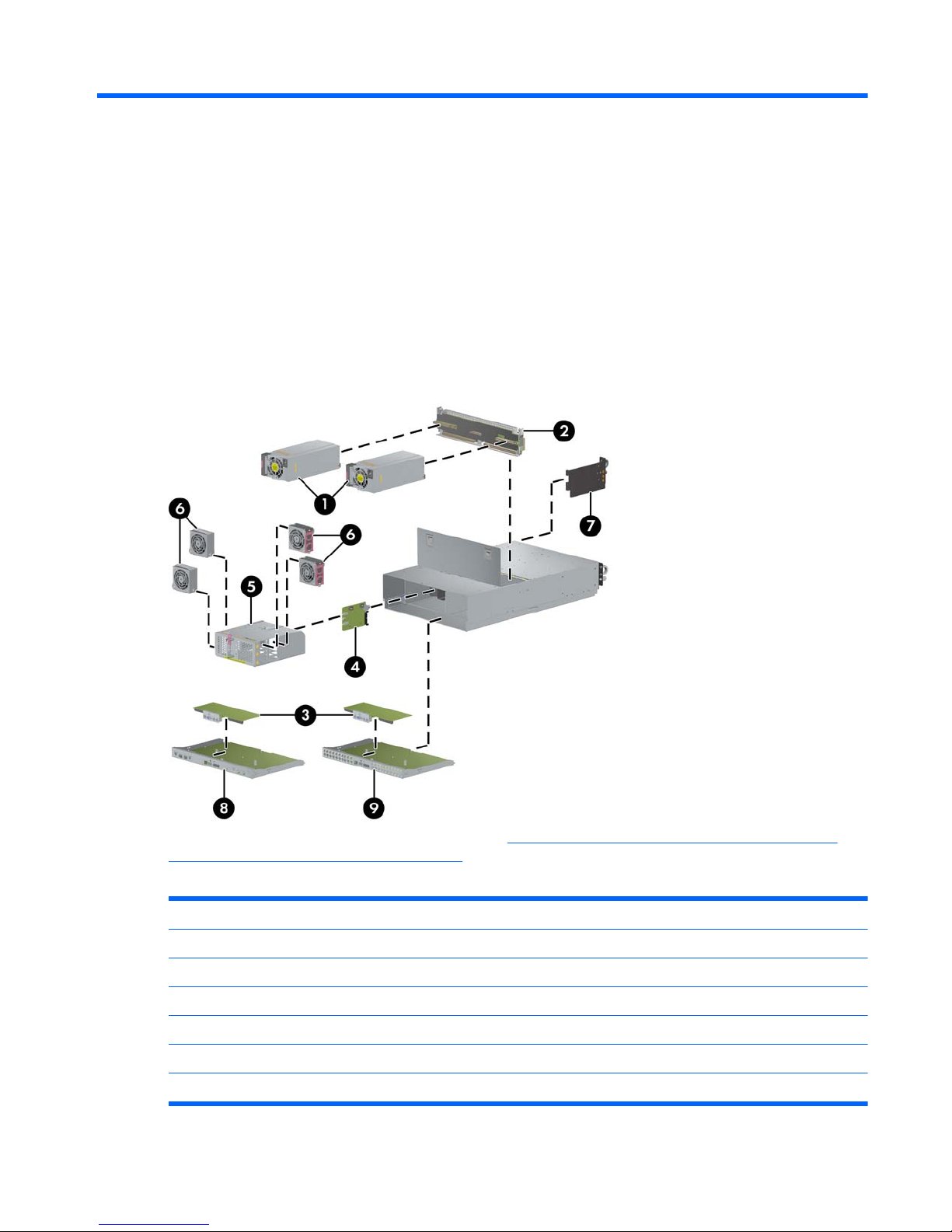
Figure 2-1 Enclosure components
For detailed information about the blade PC, see http://bizsupport.austin.hp.com/bc/docs/support/
SupportManual/c01091959/c01091959.pdf.
Table 2-1 Spare Parts List
Item Description Spare Part Number
1 Hot plug power supply 493969-001
2 Center wall assembly with bracket — Enclosure/switch 493967-001
2 Center wall assembly with bracket — Enclosure patch panel 493968-001
* Midplane signal PCA assembly with bracket 510453-001
* Midplane power PCA assembly with bracket 510454-001
3 Integrated Administrator (IA) module n/a
HP BladeSystem PC Blade Enclosure Components (Exploded View) 3
Page 10

4 Fan backplane assembly with cable 510553-001
5 Fan cage n/a
6 Hot-plug fan, 80 mm 417425-001
7 Enclosure status assembly n/a
8 HP PC Blade Switch assembly (with IA board) n/a
9 HP PC Blade RJ-45 Patch Panel assembly (with IA board) n/a
*Not shown
Table 2-1 Spare Parts List (continued)
4 Chapter 2 Illustrated Parts Catalog
Page 11

3 Removal and Replacement Procedures
This chapter provides information about the subassembly/module-level removal and replacement
procedures for HP PC Blade Enclosures with reference to HP Blade PCs.
Safety Considerations
Before performing service procedures, review the following safety information.
Electrostatic Discharge
A discharge of static electricity can damage static-sensitive devices or microcircuitry. Proper
packaging and grounding techniques are necessary to prevent damage. To prevent electrostatic
damage, observe the following precautions:
●
Transport products in static-safe containers such as conductive tubes, bags, or boxes.
● Keep electrostatic-sensitive parts in their containers until they arrive at static-free stations.
● Cover workstations with approved static-dissipating material. Use a wrist strap connected to the
work surface and properly grounded tools and equipment.
● Keep the work area free of non-conductive materials such as ordinary plastic assembly aids and
foam packing.
●
Always be properly grounded when touching a static-sensitive component or assembly.
● Avoid touching pins, leads, or circuitry.
● Use conductive field service tools.
Symbols on Equipment
These symbols may be located on equipment in areas where hazardous conditions may exist.
This symbol in conjunction with any of the following symbols indicates the presence of a potential
hazard. The potential for injury exists if warnings are not observed. Consult the documentation for
specific details.
This symbol indicates the presence of hazardous energy circuits or electric shock hazards. Refer all
servicing to qualified personnel.
WARNING! To reduce the risk of injury from electric shock hazards, do not open this enclosure.
Refer all maintenance, upgrades, and servicing to qualified personnel.
Safety Considerations 5
Page 12
This symbol indicates the presence of electric shock hazards. The area contains no user or field
serviceable parts. Do not open for any reason.
WARNING! To reduce the risk of injury from electric shock hazards, do not open this enclosure.
This symbol on an RJ-45 receptacle indicates a Network Interface Connection.
WARNING! To reduce the risk of electric shock, fire, or damage to the equipment, do not plug
telephone or telecommunications connectors into this receptacle.
This symbol indicates the presence of a hot surface or hot component. If this surface is contacted, the
potential for injury exists.
WARNING! To reduce the risk of injury from a hot component, allow the surface to cool before
touching.
These symbols on power supplies or systems indicate the equipment is supplied by multiple sources of
power.
WARNING! To reduce the risk of injury from electric shock, remove all power cords to completely
disconnect power from the system.
Weight kg
Weight lb
This symbol indicates that the component exceeds the recommended weight for one individual to
handle safely.
WARNING! To reduce the risk of personal injury or damage to the equipment, observe local
occupational health and safety requirements and guidelines for manual material handling.
Rack Warnings and Cautions
WARNING! To reduce the risk of personal injury or damage to the equipment, adequately stabilize
the rack before extending a component outside the rack. Extend only one component at a time. A
rack may become unstable if more than one component is extended.
WARNING! To reduce the risk of personal injury or damage to the equipment:
– Extend the leveling jacks to the floor.
– Rest the full weight of the rack on the leveling jacks.
– Attach the stabilizers to the rack if it is a single rack installation.
– Couple the racks together in multiple rack installations.
WARNING! When installing the HP PC Blade Enclosure in a Telco rack, adequately secure the rack
frame to the building structure at the top and bottom.
6 Chapter 3 Removal and Replacement Procedures
Page 13

WARNING! To reduce the risk of personal injury or damage to the equipment, use two or more
people to safely unload the rack from the pallet. An empty 42U rack weighs 115 kg (253 lb), is over
2.1 m (7 ft) tall, and may become unstable when moved on its casters. Handle the rack from both
sides as it rolls down the ramp from the pallet. Do not stand in front of the rack.
CAUTION: Always begin by mounting the heaviest item on the bottom of the rack. Continue to
populate the rack from the bottom to the top.
Enclosure and HP Blade PC Warnings and Cautions
WARNING! The DPS-1200KB power supply must be used in the HP PC Blade Enclosure G2. No
other power supply may be used. Attempting to use a different power supply in the HP PC blade
Enclosure G2, or attempting to use the DPS-1200KB power supply in a different enclosure, may
result in damage to your equipment. The DPS-1200KB power supply ships with a bright yellow label
attached for easy identification.
WARNING! To reduce the risk of personal injury from hot surfaces, allow the drives and the internal
system components to cool before touching.
WARNING! To reduce the risk of electric shock or damage to the equipment:
– Plug the power cords into a grounded (earthed) electrical outlet that is easily accessible at all times.
– Unplug the power cord from each power supply to disconnect power to the enclosure.
WARNING! Because the rack enables you to stack enclosure components in a vertical rather than a
horizontal plane, you must take precautions to provide for rack stability and safety to protect both
personnel and property. Heed all cautions and warnings throughout the installation instructions that
came with the enclosure.
WARNING! There is a risk of injury or damage to the equipment from hazardous energy. The
access door provides access to hazardous energy currents. The door should remain locked during
normal operation, or the HP PC Blade Enclosure should be installed in a controlled access location
where only qualified personnel have access to the system.
CAUTION: Protect the HP PC Blade Enclosure from power fluctuations and temporary interruptions
with a regulating uninterruptible power supply (UPS). This device protects the hardware from damage
caused by power surges and voltage spikes and keeps the system in operation during a power
failure.
Hot-Plug Procedures
You do not need to power down the enclosure to remove or replace hot-plug components. Hot-plug
components in the HP BladeSystem PC Blade Enclosure include:
●
Hot-plug power supplies
●
Hot-plug fans
Hot-Plug Procedures 7
Page 14
Hot-Plug Power Supplies
WARNING! The DPS-1200KB power supply must be used in the HP PC Blade Enclosure G2. No
other power supply may be used. Attempting to use a different power supply in the HP PC blade
Enclosure G2, or attempting to use the DPS-1200KB power supply in a different enclosure, may
result in damage to your equipment. The DPS-1200KB power supply ships with a bright yellow label
attached for easy identification.
CAUTION: To avoid a thermal event, do not remove a failed power supply until a replacement
power supply is available.
NOTE: You can use the Integrated Administrator to identify a failed power supply. Refer to the HP
Integrated Administrator User Guide for details.
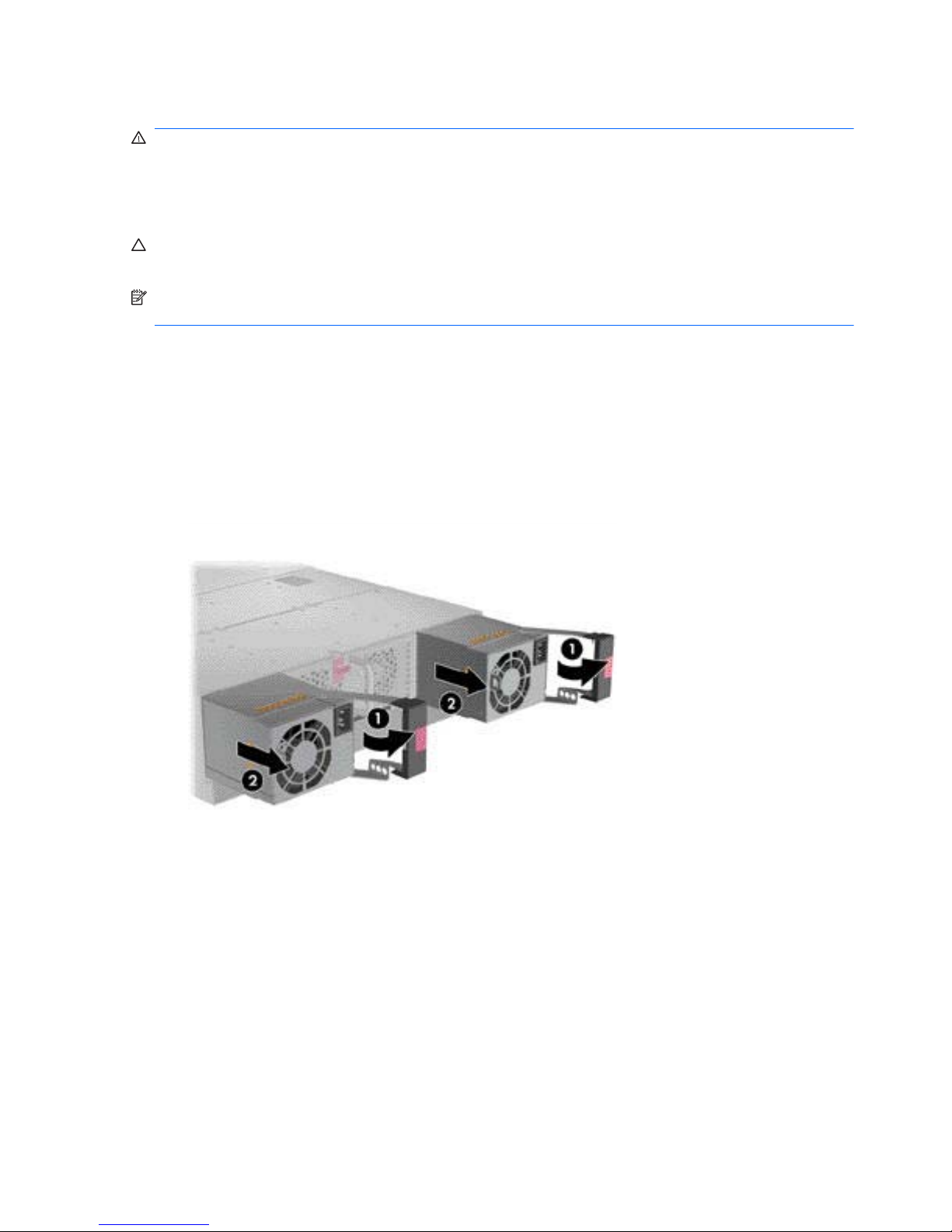
To remove a redundant hot-plug power supply:
1. Disconnect the power cord from the AC power source.
2. Disconnect the power cord from the hot-plug power supply.
3. Press the port-colored release button and open the hot-plug power supply handle (1).
4. Pull the hot-plug power supply out of the enclosure (2).
Figure 3-1 Removing a hot-plug power supply
Reverse the previous steps to replace the hot-plug power supply.
8 Chapter 3 Removal and Replacement Procedures
Page 15
Hot-Plug Fans
NOTE: You can use the Integrated Administrator to identify a failed hot-plug fan. Refer to the HP
Integrated Administrator User Guide for details.
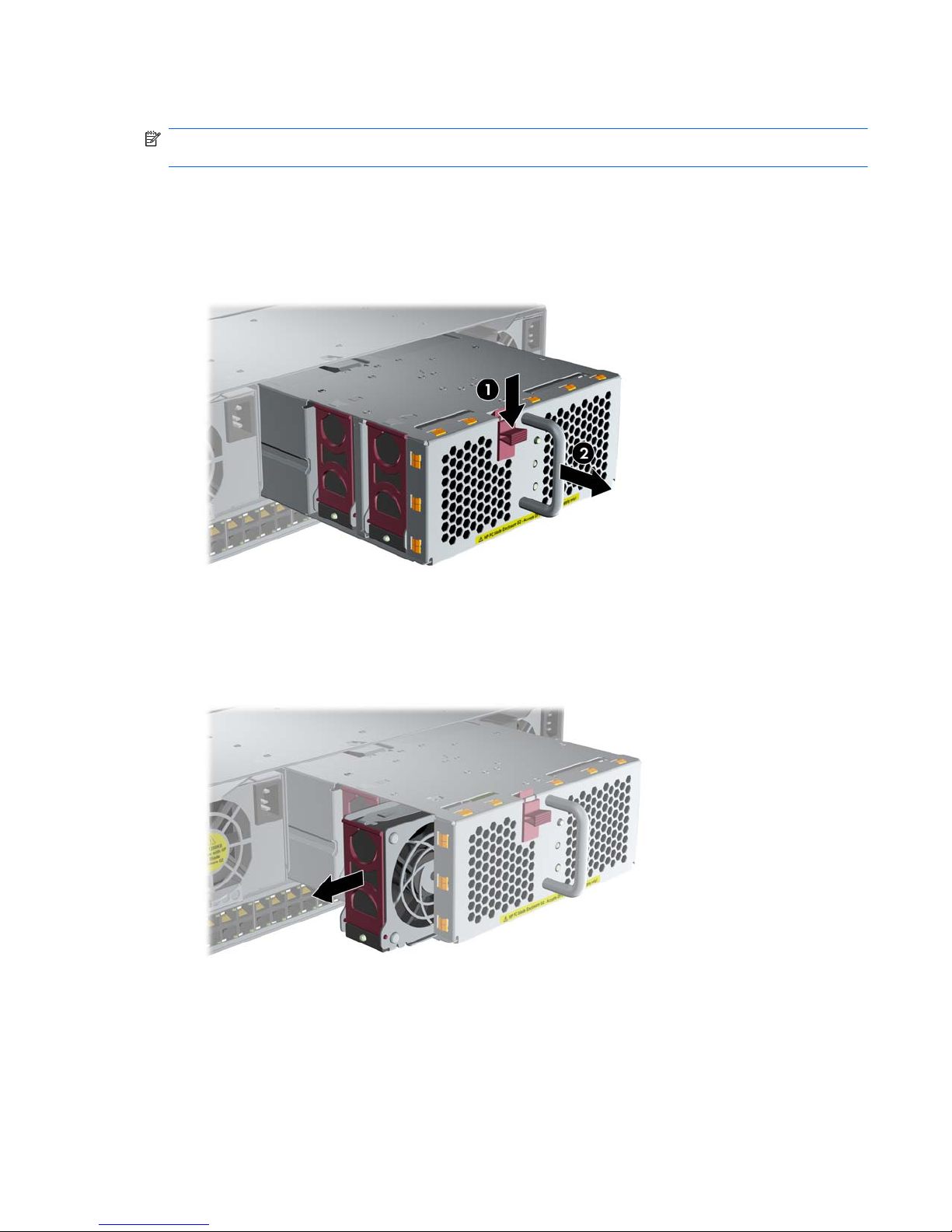
To remove a hot-plug fan:
1. Press the release latch on the fan cage (1).
2. Pull the fan cage out of the enclosure until it locks in the open position (2).
Figure 3-2 Extending the fan cage
3. Identify the failed hot-plug fan by observing the fan status LED on each hot-plug fan. An amber
LED indicates a failed hot-plug fan.
4. Remove the hot-plug fan from the fan cage.
Figure 3-3 Removing a hot-plug fan
Reverse the previous steps to replace a hot-plug fan.
Hot-Plug Procedures 9
Page 16

Preparing for Non-Hot-Plug Procedures
Replacement of non-hot-plug components may require some or all of the following procedures:
1. Powering down an HP Blade PC (
Powering Down a Blade PC on page 12).
2. Powering down the HP PC Blade Enclosure (
Powering Down the Enclosure on page 10).
3. Removing an HP Blade PC (
Removing a Blade PC on page 13).
4. Removing an HP Blade PC blank bezel (
Removing an HP Blade PC Blank Bezel on page 14).
5. Removing the interconnect tray (
Removing the Interconnect Tray on page 15).
6. Removing the HP PC Blade Enclosure from the rack (
Removing the HP PC Blade Enclosure
from the Rack on page 16).
7. Opening the access door (
Opening the Access Door on page 17).
Powering Down the Enclosure
Two different methods are available for powering down an HP BladeSystem PC Blade Enclosure:
● Graceful shutdown
●
Emergency shutdown
Performing a Graceful Shutdown
Two methods are available for performing a graceful shutdown on an HP BladeSystem PC Blade
Enclosure:
●
Using the Integrated Administrator
●
Pressing the HP PC Blade Enclosure power button
Using the Integrated Administrator
You can perform a graceful shutdown of an HP BladeSystem PC Blade Enclosure by using the
POWEROFF ENCLOSURE command in the Integrated Administrator. To power down the enclosure
using the Integrated Administrator, refer to the HP Integrated Administrator User Guide.
CAUTION: If the Integrated Administrator cannot perform a graceful shutdown of the enclosure and
all HP Blade PCs, after five minutes, the Integrated Administrator will perform an emergency
shutdown of the enclosure and all HP Blade PCs. Performing an emergency shutdown on the
enclosure may result in the loss of user connectivity and the loss of any unsaved data on all HP Blade
PCs in that enclosure.
Pressing the Enclosure Power Button
You can also perform a graceful shutdown of an HP BladeSystem PC Blade Enclosure and all the HP
Blade PCs by pressing the enclosure power button on the rear of the enclosure. If the HP Blade PC
operating system is Microsoft Windows XP or Vista, the enclosure automatically performs a graceful
shutdown of all HP Blade PCs, and then removes power from the enclosure. If the operating system
is RedHat Linux, you must have ACPI enabled for the HP Blade PCs to shut down gracefully.
10 Chapter 3 Removal and Replacement Procedures
Page 17
Performing an Emergency Shutdown
Two methods are available for performing an emergency shutdown on the enclosure and all HP
Blade PCs:
●
Using the Integrated Administrator
●
Pressing and holding the enclosure power button
Using the Integrated Administrator
The Integrated Administrator performs an emergency shutdown of the enclosure and all HP Blade
PCs only after trying for five minutes to perform a graceful shutdown. For more information, see the
Performing a Graceful Shutdown on page 10. If, after five minutes, the Integrated Administrator
cannot perform a graceful shutdown on the enclosure and all HP Blade PCs, the Integrated
Administrator performs an automatic emergency shutdown. To power down the enclosure using the
Integrated Administrator, refer to the HP Integrated Administrator User Guide for detailed instructions.
Pressing and Holding the Enclosure Power Button
You can also perform an emergency shutdown of an HP BladeSystem PC Blade Enclosure and all
HP Blade PCs by pressing and holding the power button on the rear of the enclosure for four
seconds.
CAUTION: Performing an emergency shutdown on an HP Blade PC may result in the loss of any
unsaved data on all HP Blade PCs in that enclosure.
Briefly press the button again to power up the HP BladeSystem PC Blade Enclosure.
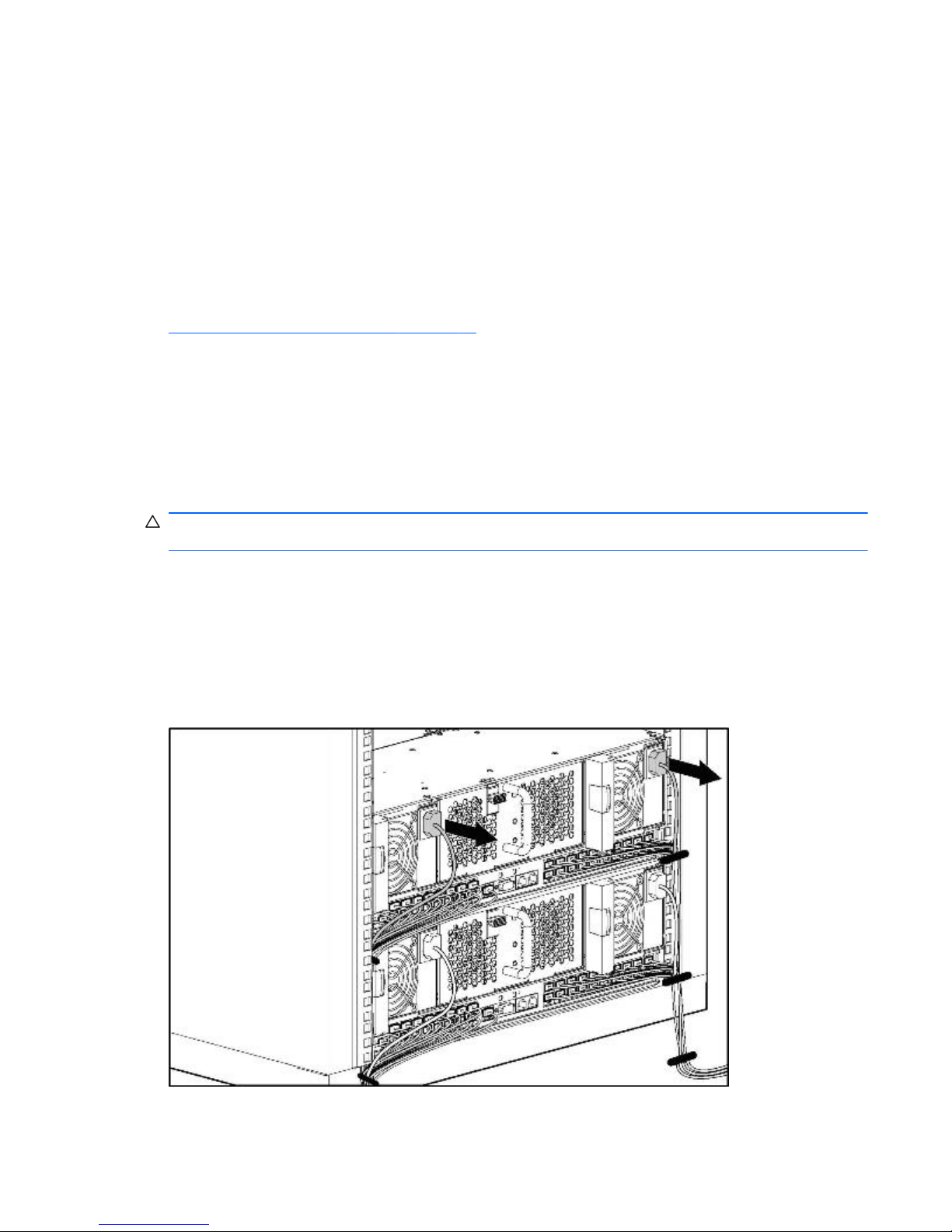
Completely Removing AC Power
To completely remove power from the enclosure and all HP Blade PCs, after powering down the
enclosure, disconnect both of the power cords from the AC power source, then disconnect both of the
power cords from the rear panel of the enclosure.
Figure 3-4 Disconnecting the power cords from the rear panel
Reverse these steps to power up the enclosure.
Preparing for Non-Hot-Plug Procedures 11
Page 18
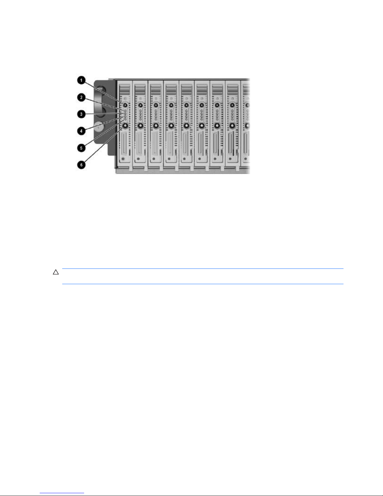
Powering Down a Blade PC
1. Ensure the blade PC is not active by verifying that the Health LED (Item 2) is off.
Figure 3-5 Blade PC LEDs
2. If the blade is active, notify the users and stop applications as necessary.
3. Shut down the operating system. This may shut off the blade PC power.
4. If the blade PC still has power, power down the blade PC by either:
●
Using the Integrated Administrator, or
●
Pressing the power button (6) on the front of the blade PC above.
To perform an emergency shut down of the blade PC, press and hold the blade power button for four
seconds.
CAUTION: Performing an emergency shutdown on a blade PC may result in the loss of any
unsaved data.
12 Chapter 3 Removal and Replacement Procedures
Page 19
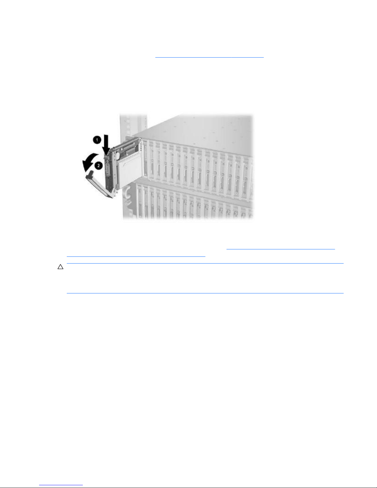
Removing a Blade PC
1. Power down the blade PC (Powering Down a Blade PC on page 12).
2. Press the release latch (1).
3. Pull down the ejector lever (2).
4. Remove the blade PC from the enclosure.
Figure 3-6 Removing a blade PC
To install a new blade PC, reverse the removal procedures.
For more information, see the Service Reference Guide at
http://bizsupport.austin.hp.com/bc/docs/
support/SupportManual/c01091959/c01091959.pdf.
CAUTION: Integrated Administrator security settings are assigned to HP Blade PC bays, not to HP
Blade PCs. If HP Blade PCs change locations within the enclosure, Integrated Administrator settings
must also be adjusted to ensure accurate security. Refer to the HP Integrated Administrator User
Guide for more information on security settings.
Preparing for Non-Hot-Plug Procedures 13
Page 20
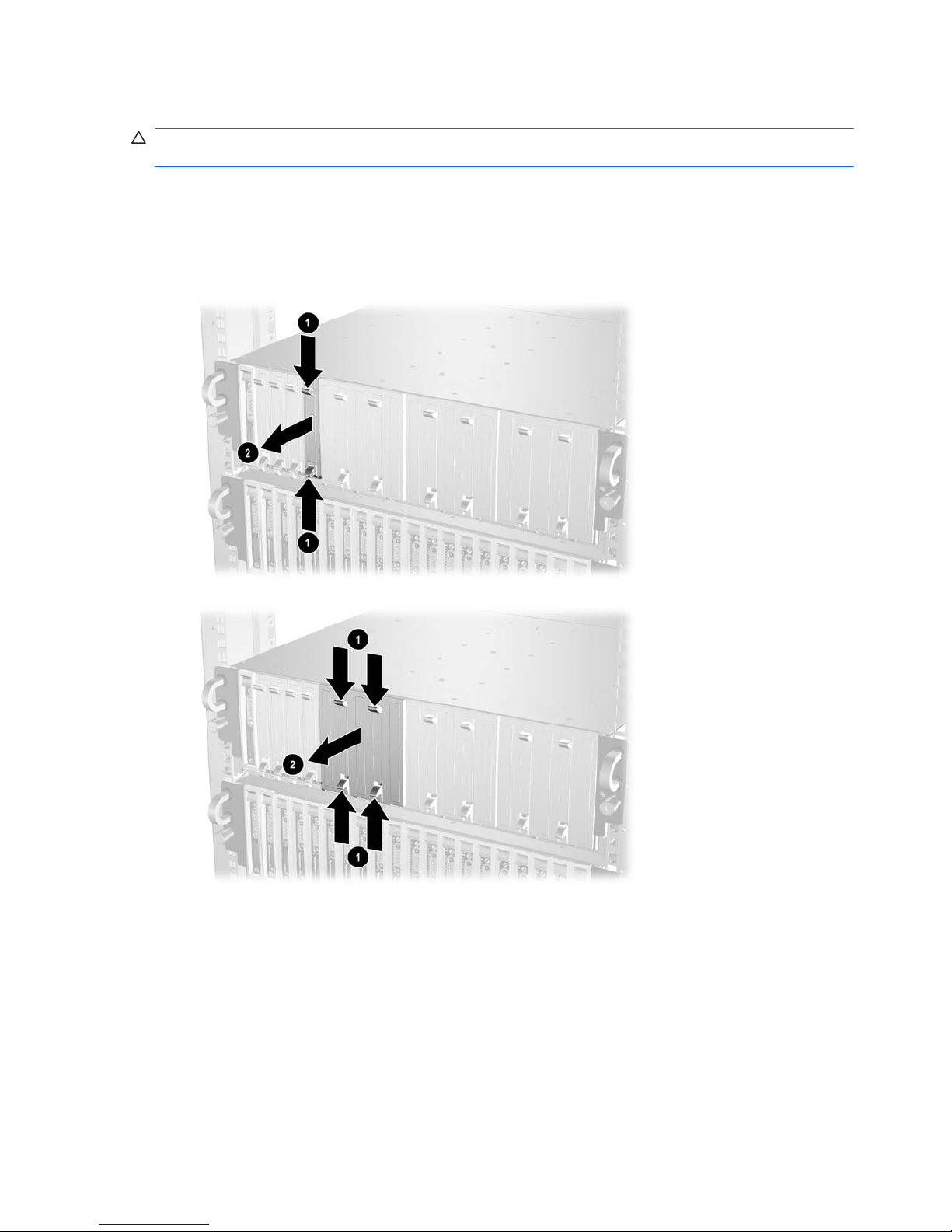
Removing an HP Blade PC Blank Bezel
CAUTION: To avoid thermal events, be sure that each HP Blade PC bay contains an HP Blade PC
or HP Blade PC blank bezel while the enclosure is powered up.
To remove the HP Blade PC blank bezel:
1. Press the ejector tabs on the HP Blade PC blank bezel (1).
2. Remove the HP Blade PC blank bezel from the enclosure (2).
Figure 3-7 Removing a one-bay HP Blade PC blank bezel
Figure 3-8 Removing a five-bay HP Blade PC blank bezel
Reverse the previous steps to replace the HP Blade PC blank bezel.
14 Chapter 3 Removal and Replacement Procedures
Page 21
Removing the Interconnect Tray
To remove the interconnect tray:
1. Power down each HP Blade PC (
Powering Down a Blade PC on page 12).
2. Power down the enclosure (
Powering Down the Enclosure on page 10).
3. Disconnect all cables and power cords from the AC power source.
4. Disconnect all cables and power cords from the enclosure rear panel.
5. Remove both hot-plug power supplies (
Hot-Plug Power Supplies on page 8).
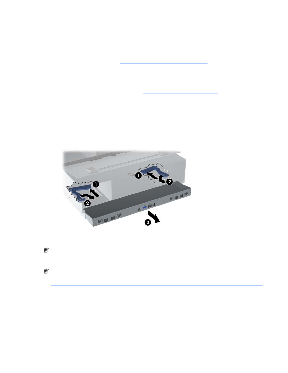
6. Push the locking latches toward the front of the enclosure to expose the release latches securing
the interconnect tray in the enclosure (1).
7. Pull the release latches toward the rear of the enclosure (2).
8. Remove the interconnect tray from the enclosure (3).
Figure 3-9 Removing the interconnect tray from the enclosure
NOTE: Perform step 6 simultaneously in both power supply bays.
Reverse the previous steps to replace the interconnect tray.
NOTE: When installing the interconnect tray, be sure that the release latches are in the open
position. When closing the release latches on the interconnect tray, be sure that the locking latches
click audibly into place.
Preparing for Non-Hot-Plug Procedures 15
Page 22
Removing the HP PC Blade Enclosure from the Rack
WARNING! Rack rails do not have safety latches. Be sure that at least two persons are available to
prevent the enclosure from falling and causing bodily harm when removing it from the rack.
To remove the HP PC Blade Enclosure from the rack:
1. Power down each HP Blade PC (
Powering Down a Blade PC on page 12).
2. Power down the enclosure (
Powering Down the Enclosure on page 10).
3. Disconnect all cables and power cords from the AC power source.
4. Disconnect all cables and power cords from the enclosure rear panel.
5. Remove all HP Blade PCs and HP Blade PC blank bezels (
Removing an HP Blade PC Blank
Bezel on page 14).
6. Remove both hot-plug power supplies (
Hot-Plug Power Supplies on page 8).
7. Remove the interconnect tray (
Removing the Interconnect Tray on page 15).
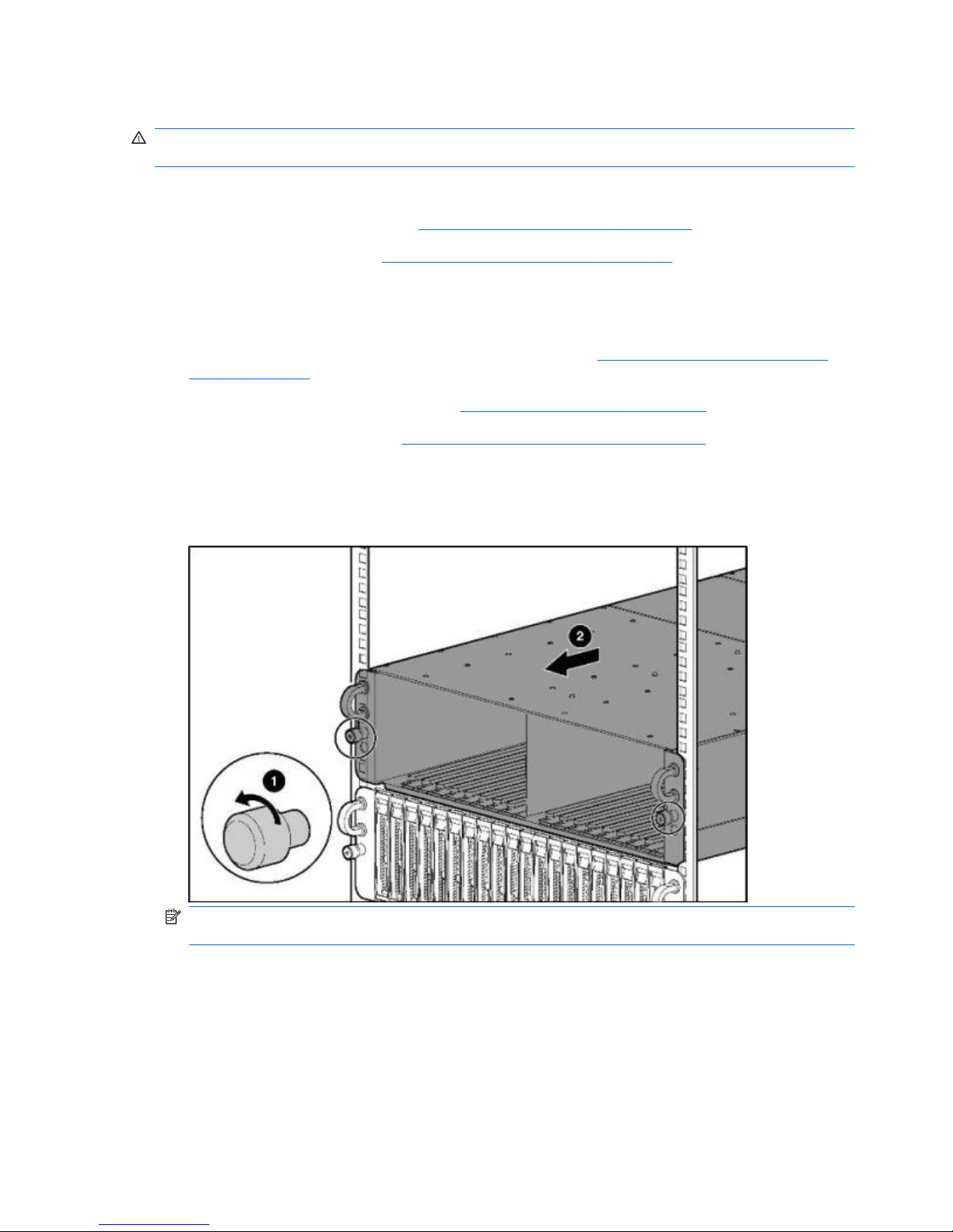
8. Loosen the thumbscrews on the front of the enclosure (1).
9. Remove the enclosure from the rack (2).
Figure 3-10 Removing the enclosure from the rack
NOTE: Pull the enclosure out using the handles. Pulling the enclosure by the thumbscrews
damages the thumbscrews.
Reverse the previous steps to install the enclosure into the rack.
16 Chapter 3 Removal and Replacement Procedures
Page 23
Opening the Access Door
To open the access door:
1. Power down each HP Blade PC (
Powering Down a Blade PC on page 12).
2. Power down the enclosure (
Powering Down the Enclosure on page 10).
3. Disconnect all cables and power cords from the AC power source.
4. Disconnect all cables and power cords from the enclosure rear panel.
5. Remove all HP Blade PCs and HP Blade PC blank bezels (
Removing a Blade PC on page 13
and
Removing an HP Blade PC Blank Bezel on page 14).
CAUTION: Integrated Administrator security settings are assigned to HP PC Blade Enclosure
bays, not to HP Blade PCs. If HP Blade PCs change locations within the enclosure, Integrated
Administrator settings must also be adjusted to ensure accurate security. Refer to the HP
Integrated Administrator User Guide for more information on security settings.
6. Remove the enclosure from the rack (Removing the HP PC Blade Enclosure from the Rack
on page 16).
7. Place the enclosure on a level, non-conductive surface.
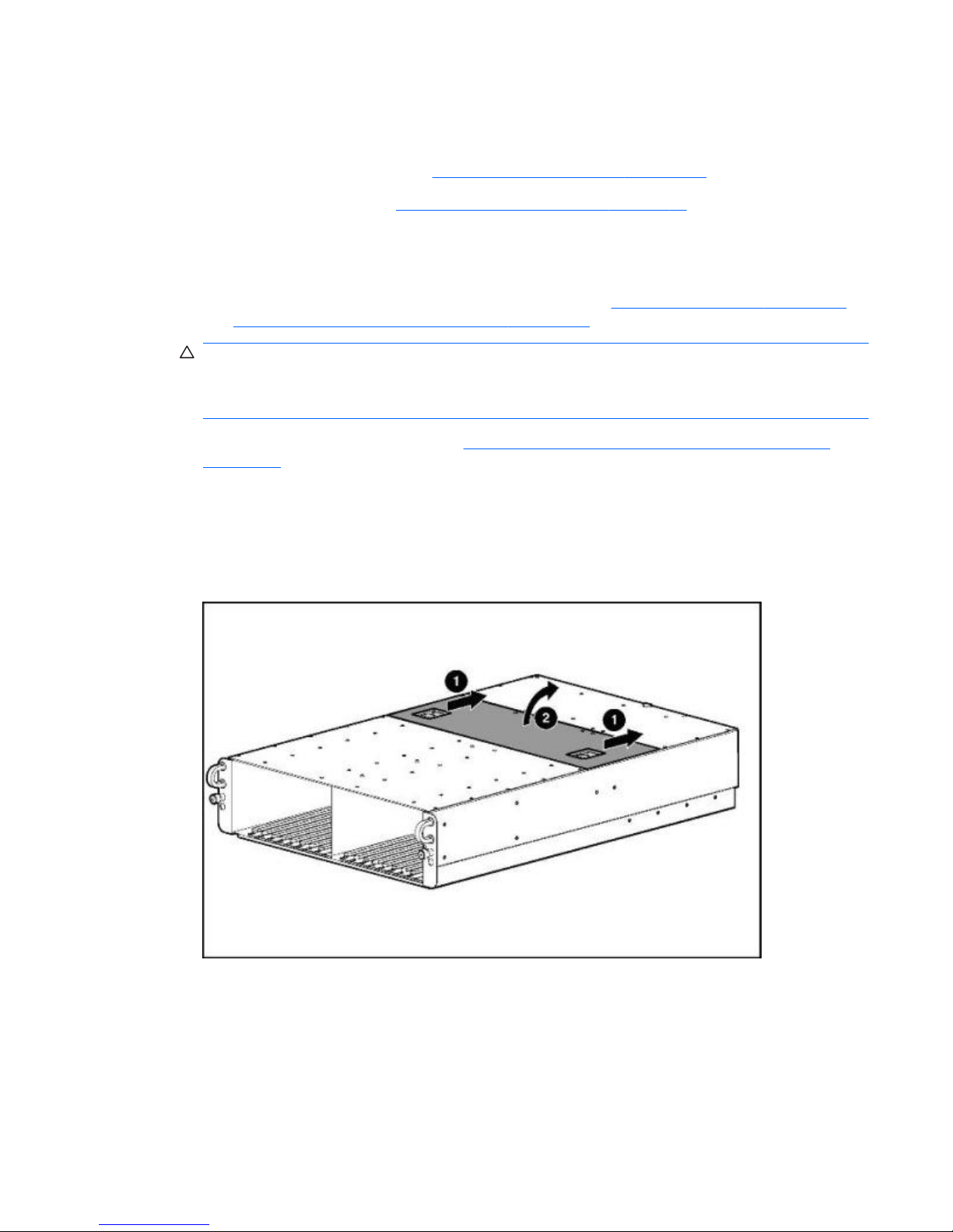
8. Release the latches on the access door (1).
9. Open the access door (2).
Figure 3-11 Opening the access door
Preparing for Non-Hot-Plug Procedures 17
Page 24

Non-Hot-Plug Procedures
Before removing or replacing non-hot-plug components, you must power down the HP PC Blade
Enclosure completely. Non-hot-plug components in the HP BladeSystem PC Blade Enclosure system
include:
●
Fan cage
●
Fan backplane assembly
●
Interconnect tray
●
Integrated Administrator module
●
Enclosure status assembly
●
Midplane assembly
Fan Cage
To remove the fan cage:
1. Power down each HP Blade PC (
Powering Down a Blade PC on page 12).
2. Power down the enclosure. For more information see the
Powering Down the Enclosure
on page 10.
3. Disconnect all cables and power cords from the AC power source.
4. Disconnect all cables and power cords from the enclosure rear panel.
5. Remove all HP Blade PCs (
Removing a Blade PC on page 13).
CAUTION: Integrated Administrator security settings are assigned to HP PC Blade Enclosure
bays, not to HP Blade PCs. If HP Blade PCs change locations within the enclosure, Integrated
Administrator settings must also be adjusted to ensure accurate security. Refer to the HP
Integrated Administrator User Guide for more information on security settings.
6. Remove both hot-plug power supplies (Hot-Plug Power Supplies on page 8).
7. Remove the interconnect tray (
Removing the Interconnect Tray on page 15).
8. Remove the enclosure from the rack (
Removing the HP PC Blade Enclosure from the Rack
on page 16).
9. Place the enclosure on a level, non-conductive surface.
10. Open the access door (1) (
Opening the Access Door on page 17).
11. Press the fan cage release latch (2).
12. Pull the fan cage out of the enclosure until it locks in the open position (3).
13. Open the latches on the cable connector (4).
14. Disconnect the fan cable from the midplane (power board) (5).
15. Press the fan cage removal latch on top of the fan cage (6).
18 Chapter 3 Removal and Replacement Procedures
Page 25

16. Remove the fan cage from the enclosure (7).
Figure 3-12 Removing the fan cage from the enclosure
Reverse the previous steps to replace the fan cage.
Fan Backplane Assembly
To remove the fan backplane assembly:
1. Power down each HP Blade PC (
Powering Down a Blade PC on page 12).
2. Power down the enclosure (
Powering Down the Enclosure on page 10).
3. Disconnect all cables and power cords from the AC power source.
4. Disconnect all cables and power cords from the enclosure rear panel.
5. Remove all HP Blade PCs (Removing a Blade PC on page 13).
CAUTION: Integrated Administrator security settings are assigned to HP PC Blade Enclosure
bays, not to HP Blade PCs. If HP Blade PCs change locations within the enclosure, Integrated
Administrator settings must also be adjusted to ensure accurate security. Refer to the HP
Integrated Administrator User Guide for more information on security settings.
6. Remove both hot-plug power supplies (Hot-Plug Power Supplies on page 8).
7. Remove the interconnect tray (
Removing the Interconnect Tray on page 15).
8. Remove the enclosure from the rack (
Removing the HP PC Blade Enclosure from the Rack
on page 16).
9. Place the enclosure on a level, non-conductive surface.
10. Open the access door (
Opening the Access Door on page 17).
11. Disconnect the fan cable from the power backplane.
12. Remove the fan cage (
Fan Cage on page 18).
Non-Hot-Plug Procedures 19
Page 26

13. Remove the hot-plug fans (Hot-Plug Fans on page 9).
14. Loosen the thumbscrew at the back of the fan cage (1).
15. Remove the fan backplane assembly from the fan cage (2).
Figure 3-13 Removing the fan backplane assembly
Reverse the previous steps to replace the fan backplane assembly.
Integrated Administrator Module
The Integrated Administrator module removal procedure is the same for both types of interconnect
trays.
To remove the Integrated Administrator module:
1. Power down each HP Blade PC (
Powering Down a Blade PC on page 12).
2. Power down the enclosure (
Powering Down the Enclosure on page 10).
3. Disconnect all cables and power cords from the AC power source.
4. Disconnect all cables and power cords from the enclosure rear panel.
5. Remove both hot-plug power supplies (
Hot-Plug Power Supplies on page 8).
6. Remove the interconnect tray from the enclosure (
Removing the Interconnect Tray on page 15).
7. Rotate the three quarter-turn posts on the Integrated Administrator module 90 degrees (1).
8. Remove the two screw locks with a 5-mm Torques driver (2).
9. Loosen the two screws (3) that secure the hold down clamps for the IA and rotate one half turn
(90 degrees) from the edges of the IA board.
20 Chapter 3 Removal and Replacement Procedures
Page 27

10. Lift the Integrated Administrator module off the anchor pins, and then remove the Integrated
Administrator module from the interconnect tray (4).
Figure 3-14 Removing the Integrated Administrator module from the interconnect tray
Reverse the previous steps to replace the Integrated Administrator module.
Enclosure Status Assembly
To remove the enclosure status assembly:
1. Power down each HP Blade PC (
Powering Down a Blade PC on page 12).
2. Power down the enclosure (
Powering Down the Enclosure on page 10).
3. Disconnect all cables and power cords from the AC power source.
4. Disconnect all cables and power cords from the enclosure rear panel.
5. Remove all HP Blade PCs and HP Blade PC blank bezels (
Removing a Blade PC on page 13
and
Removing an HP Blade PC Blank Bezel on page 14).
CAUTION: Integrated Administrator security settings are assigned to HP PC Blade Enclosure
bays, not to HP Blade PCs. If HP Blade PCs change locations within the enclosure, Integrated
Administrator settings must also be adjusted to ensure accurate security. Refer to the HP
Integrated Administrator User Guide for more information about security settings.
6. Remove both hot-plug power supplies (Hot-Plug Power Supplies on page 8).
7. Remove the interconnect tray from the enclosure (
Removing the Interconnect Tray on page 15).
8. Remove the enclosure from the rack (
Removing the HP PC Blade Enclosure from the Rack
on page 16).
Non-Hot-Plug Procedures 21
Page 28

9. Place the enclosure on a level, non-conductive surface.
10. Open the access door (
Opening the Access Door on page 17).
11. Disconnect the enclosure status cable from the midplane (signal board).
Figure 3-15 Disconnecting the enclosure status cable from the midplane signal board
12. Remove the screws securing the enclosure status assembly in the enclosure (1).
13. Remove the enclosure status assembly from the enclosure (2).
Figure 3-16 Removing the enclosure status assembly from the enclosure
Reverse the previous steps to replace the enclosure status assembly.
22 Chapter 3 Removal and Replacement Procedures
Page 29

Midplane Assembly
To remove the midplane assembly:
1. Power down each HP Blade PC (
Powering Down a Blade PC on page 12).
2. Power down the enclosure (
Powering Down the Enclosure on page 10).
3. Disconnect all cables and power cords from the AC power source.
4. Disconnect all cables and power cords from the enclosure rear panel.
5. Remove all HP Blade PCs (
Removing a Blade PC on page 13).
CAUTION: Integrated Administrator security settings are assigned to HP PC Blade Enclosure
bays, not to HP Blade PCs. If HP Blade PCs change locations within the enclosure, Integrated
Administrator settings must also be adjusted to ensure accurate security. Refer to the HP
Integrated Administrator User Guide for more information on security settings.
6. Remove both hot-plug power supplies (Hot-Plug Power Supplies on page 8).
7. Remove the interconnect tray from the enclosure (
Removing the Interconnect Tray on page 15).
8. Remove the enclosure from the rack (
Removing the HP PC Blade Enclosure from the Rack
on page 16).
9. Place the enclosure on a level, non-conductive surface.
10. Open the access door (
Opening the Access Door on page 17).
11. Disconnect the fan cable from the midplane (power board) (
Fan Backplane Assembly
on page 19).
12. Disconnect the enclosure status cable from the midplane (signal board) (
Enclosure Status
Assembly on page 21).
13. Loosen the thumbscrews on the midplane assembly (1).
Non-Hot-Plug Procedures 23
Page 30

14. Remove the midplane assembly from the enclosure (2).
Figure 3-17 Removing the midplane assembly from the enclosure
Reverse the previous steps to replace the midplane assembly.
Swapping the Interconnect Tray
To swap the existing interconnect tray with a replacement interconnect tray:
1. Remove the interconnect tray from the enclosure (
Removing the Interconnect Tray on page 15).
2. Remove the Integrated Administrator module from the interconnect tray (
Integrated
Administrator Module on page 20).
3. Place the replacement interconnect tray on a level, non-conductive surface.
4. Position the Integrated Administrator module so that its holes are aligned with the anchor pins of
the replacement interconnect tray (1).
5. Rotate the three anchor pins 90 degrees to lock the Integrated Administrator module into
position (2).
6. Replace the two screw locks (3).
24 Chapter 3 Removal and Replacement Procedures
Page 31

7. Secure the two hold down clamps to the opposite edges of the Integrated Administrator board,
and then tighten the two screws (4).
NOTE: The Integrated Administrator board is spared as part of the interconnect tray assembly
within the standard warranty period.
Figure 3-18 Installing the Integrated Administrator module onto the interconnect tray
Replace the interconnect tray. For more information, see Removing the Interconnect Tray
on page 15.
Non-Hot-Plug Procedures 25
Page 32

4 Diagnostic Tools
This chapter is an overview of hardware, software, and firmware diagnostic tools that are available for
configuring, monitoring, and managing HP BladeSystem PC Blade systems.
Diagnostic Software and Firmware Tools
The HP Integrated Administrator is a standard component of the HP BladeSystem PC Blade
Enclosure system. The Integrated Administrator provides enclosure health, HP Blade PC health, and
remote server manageability. Integrated Administrator features are accessed from any network-based
client using a supported Web browser. In addition to other features, Integrated Administrator provides
keyboard and mouse capability for an HP Blade PC, regardless of the state of the host operating
system or host HP Blade PC.
Use the following tools to diagnose problems, test hardware, and monitor and manage HP
BladeSystem PC Blade system operations.
Table 4-1 Diagnostic tools
Tool Description How to run the tool
HP Integrated
Administrator (IA)
The HP Integrated Administrator is a centralized
management and monitoring system for the HP
BladeSystem PC Blade enclosure and HP Blade
PCs. The Integrated Administrator acts as a
combination web/console server and remote
power controller, enabling in-band or out-ofband, secure, serial console connections to all
HP Blade PCs in the enclosure.
Refer to the HP Integrated Administrated User
Guide for complete details.
The Integrated Administrator keeps a system
log resident and records and health diagnostic
information provided by the blade PC.
Additionally, the IA can receive additional status
information from blade PCs equipped with a
blade management controller (BMC) including
network (PXE) boot status, diagnostic adaptor
present, POST boot completion, front IO
blanking mode, and ASR mode status (requires
at least IA version 4.30 and BMC version 25h).
Automatic Server
Recovery-2 (ASR-2)
ASR-2 automatically restarts a HP Blade PC
after a catastrophic operating system failure.
With ASR-2, you have multiple recovery options:
●
Available Recovery provides software error
recovery and environmental recovery.
●
Unattended Recovery logs the error
information to the IA system log (IA version
4.2), resets the HP Blade PC, and tries to
restart the operating system.
Run the ROM-Based Setup Utility and set
ASR-2 to enable this tool.
26 Chapter 4 Diagnostic Tools
Page 33

HP Systems Insight
Manager (SIM)
Systems Insight Manager is a client/server
application used to remotely manage HP
hardware in a network environment. SIM reports
HP Blade PC and HP Blade PC Enclosure
hardware fault conditions (both failure and prefailure) and collects data for reporting and
graphing.
For more information on viewing and printing the
event list, refer to the Management CD or the
SIM User Guide.
ROM-Based Setup
Utility (RBSU)
RBSU configures the hardware installed in or
connected to the HP Blade PC. Specifically, it
can:
● Store configuration information in
nonvolatile memory.
●
Manage memory installation, processor
upgrades, network interface cards, and
mass storage devices.
●
Assist in installing an operating system.
● Configure connectors and IRQs, if
required.
Attach a keyboard to the HP Blade PC using the
diagnostic adapter.
Run RBSU by pressing the F10 key during
POST.
BMCFlash Utility Update utility for the Blade Management
Controller (BMC) firmware..
Flash the BMC on BC2x00 blades only.
Hardware Diagnostic Tools
The HP BladeSystem PC Blade system offers the following HP Blade PC and HP PC Blade
Enclosure hardware diagnostic tools.
Diagnostic Adapter
Use the diagnostic adapter(s) to attach peripheral devices to any individual HP Blade PC for local HP
Blade PC diagnosis and management. See
Connectors, Switches, and LEDs on page 30 for the
location of diagnostic adapter connectors.
NOTE: You can hot-add peripheral devices using the diagnostic adapter if the devices support hot-
plug capability.
1. Power down the HP Blade PC (Powering Down a Blade PC on page 12).
2. Plug the diagnostic adapter into the diagnostic connector on the HP Blade PC (1).
Table 4-1 Diagnostic tools (continued)
Hardware Diagnostic Tools 27
Page 34

3. Tighten the thumbscrews securing the diagnostic adapter in place (2).
Figure 4-1 Installing a diagnostic adapter USB 1.1 version pictured (obsolete)
4. Power up the HP Blade PC.
NOTE: Because PS/2 devices do not support hot-plug technology, restart the HP Blade PC after
attaching the diagnostic adapter. USB devices are hot-plug supported and do not require restarting
the HP Blade PC after attachment.
Table 4-2 Cable Pin Out for a Null Modem Cable
Signal name EM PIN DB 9 PIN DB 25 PIN
TxD 3 2 3
RxD 2 3 2
RTS 7 8 5
CTS 8 7 4
GND 5 5 7
DSR 6 4 20
CD 1 4 20
28 Chapter 4 Diagnostic Tools
Page 35

Figure 4-2 Installing a diagnostic adapter USB 2.0 version
Table 4-3 Cable Pin Out for a Null Modem Cable
Signal name EM PIN DB 9 PIN DB 25 PIN
TxD 3 2 3
RxD 2 3 2
RTS 7 8 5
CTS 8 7 4
GND 5 5 7
DSR 6 4 20
CD 1 4 20
Null-Modem Cable Pin-Out
Use the above table(s) to determine the specifications of the cable(s). If you are cabling a serial
device (such as a laptop computer) to the console connector on the Integrated Administrator, be sure
that you use a null-modem cable and not a straight-through cable.
Hardware Diagnostic Tools 29
Page 36

5 Connectors, Switches, and LEDs
This chapter explains the location and function of system connectors, system switches, and internal
and external LEDs.
Connectors
The figures and tables on the following pages show connector locations on the HP BladeSystem
Blade PCs and HP BladeSystem PC Blade Enclosures.
Enclosure Connectors
This section explains the location and function of rear panel connectors associated with the HP PC
Blade Switch and RJ-45 patch panel interconnect tray.
Interconnect Switch Connectors
Figure 5-1 HP PC Blade Switch connectors
NOTE: bc2800 shown.
Item Description Location
(1) Gigabit Ethernet jack for port 43 Interconnect switch
(2) Socket for optional GBIC SFP module for port 43 Interconnect switch
(3) Socket for optional GBIC SFP module for port 44 Interconnect switch
(4) Gigabit Ethernet jack for port 44 Interconnect switch
30 Chapter 5 Connectors, Switches, and LEDs
Page 37

(5) 10/100 Ethernet jack for Integrated Administrator management port 42 Integrated Administrator module
(6) Integrated Administrator console connector (serial) Integrated Administrator module
(7) Gigabit Ethernet jack for port 45 Interconnect switch
(8) Socket for optional GBIC SFP module for port 45 Interconnect switch
(9) Socket for optional GBIC SFP module for port 46 Interconnect switch
(10) Gigabit Ethernet jack for port 46 Interconnect switch
CAUTION: See QuickSpecs for supported uses of the enclosure link (RJ-45) connectors on the
Integrated Administrator module. Connecting an unsupported external device to the enclosure link
(RJ-45) connectors may damage the external device.
RJ-45 Patch Panel Connectors
This section identifies the RJ-45 patch panel connectors.
Figure 5-2 RJ-45 patch panel connectors
Item Description Location
1 RJ-45 connector for HP PC Blade Enclosure bay 20 NIC B (2) RJ-45 patch panel
2 RJ-45 connector for HP PC Blade Enclosure bay 20 NIC A (1) RJ-45 patch panel
3 Integrated Administrator management connector (10/100
Ethernet)*
Integrated Administrator module
4 Integrated Administrator console connector (serial)* Integrated Administrator module
5 RJ-45 connector for HP PC Blade Enclosure bay 1 NIC A (1) RJ-45 patch panel
6 RJ-45 connector for HP PC Blade Enclosure bay 1 NIC B (2) RJ-45 patch panel
*These items denote connectors for the Integrated Administrator module.
CAUTION: See QuickSpecs for supported uses of the enclosure link (RJ-45) connectors on the
Integrated Administrator module. Connecting an unsupported external device to the enclosure link
(RJ-45) connectors may damage the external device.
Connectors 31
Page 38

Fan Cable Connector
This section identifies the connector on the midplane assembly for the fan cable.
Figure 5-3 Fan cable connector on the midplane assembly
Enclosure Status Cable Connector
This section identifies the connector on the HP PC Blade Enclosure midplane for the enclosure status
cable.
Figure 5-4 Enclosure status cable connector on the midplane assembly
32 Chapter 5 Connectors, Switches, and LEDs
Page 39

HP Blade PC Connectors
This section identifies the connectors on each HP Blade PC.
Figure 5-5 Identifying the HP Blade PC connectors
Item Description
1 Midplane assembly connectors
2 Diagnostic connector
Diagnostic Adapter Connectors (USB 1.1 and USB 2.0)
This section identifies the connectors on the diagnostic adapter version USB 1.1.
Figure 5-6 Diagnostic adapter connectors USB 1.1 version – (obsolete)
Item Description Item Description
1 Mouse connector (PS/2) 4 Serial connector
2 Keyboard connector (PS/2) 5 USB connector (1.1)
3 USB connector (1.1) 6 Video connector
Connectors 33
Page 40

This section identifies the connectors on the diagnostic adapter version USB 2.0
Figure 5-7 Diagnostic adapter connectors USB 2.0 version
Item Description
1 Keyboard connector (PS/2)
2 Mouse connector (PS/2)
3 Serial connector
4 Video connector
5 USB 2.0 connector #1
6 USB 2.0 connector #2
34 Chapter 5 Connectors, Switches, and LEDs
Page 41

Switches
With system switches, you can enable or disable certain settings or perform advanced diagnostic
procedures.
Front Panel Switches
This section identifies the location and function of the switches on the front panel of the enclosure
and HP Blade PC.
Figure 5-8 HP Blade PC and enclosure front panel buttons
Item Description Function
1 HP Blade PC unit identification button Activates the unit identification LED for easy HP Blade PC
identification
2 Enclosure unit identification button Activates the unit identification LED for easy enclosure
identification
3 HP Blade PC power button Powers up or down an HP Blade PC. (Hold down for 4
seconds to perform an emergency shutdown.)
Switches 35
Page 42

Rear Panel Switches
This section identifies the location and function of the buttons on the rear panel of the enclosure.
Figure 5-9 Enclosure rear panel buttons
NOTE: bc2800 shown.
Item Description On/Off Function
1 Enclosure unit identification button Activates the unit identification LED for easy enclosure
identification
2 Enclosure power button Powers the enclosure and all HP Blade PCs up or down
3 Integrated Administrator reset button Restarts the Integrated Administrator
CAUTION: Pressing and holding the enclosure power button for 4 seconds causes an emergency
shutdown on the enclosure and all HP Blade PCs, and may result in the loss of any unsaved data on
all HP Blade PCs.
CMOS
Press the CMOS button (labeled SW50) on the blade PC’s system board for 2 seconds to clear
CMOS.
36 Chapter 5 Connectors, Switches, and LEDs
Page 43

LEDs
The figures and tables on the following pages show the location and function of LEDs associated with
the HP BladeSystem PC Blade system.
Enclosure Front Panel LEDs
Figure 5-10 Enclosure front panel LEDs
Table 5-1 Enclosure Front Panel LEDs
Item LED Status Description
1 Enclosure unit ID (unit identification) Off Off
Blue Identification of unit
2 Enclosure health Off Enclosure off and health good
Green Enclosure on and health good
Amber Enclosure degraded: A redundant component has
failed or other fault condition – check IA for
additional information.
Red Enclosure critical: Immediate attention required,
enclosure at risk of down time
LEDs 37
Page 44

Enclosure Rear Panel LEDs
The enclosure rear panel LEDs differ according to which interconnect tray configuration you have
installed.
Rear panel LEDs with HP PC Blade Switch
Figure 5-11 Rear panel LEDs with the HP PC Blade Switch
NOTE: bc2800 shown.
This section identifies the LEDs on the enclosure rear panel with an HP PC Blade Switch .
Table 5-2 Rear panel LEDs with the HP PC Blade Switch
Item LED Status Description
1 Power supply power Off No power to the system
Blinking green Standby, AC present
Green System power turned on
2 Power supply fault Off Power supply OK
Amber No AC power or over-voltage or over-
temperature
Blinking amber Current limit
3 Enclosure power Off No power to enclosure
Amber Enclosure shutdown; power available; hibernate
Green Enclosure power on
4 Fan health Off Enclosure off, fan health good
Green Enclosure on, fan health good
Amber Fan subsystem degraded
Red Fan subsystem critical
5 Enclosure unit identification Off Unit not identified
Blue Identification of unit
38 Chapter 5 Connectors, Switches, and LEDs
Page 45

6 Integrated Administrator health Off Enclosure off, Integrated Administrator health
good
Green Enclosure on, Integrated Administrator health
good
Amber Integrated Administrator critical
7 Interconnect switch health Green Interconnect switch health good
Yellow Interconnect switch health degraded
Red Interconnect switch health critical
Off Switch booting/No power
8 Stacking Status Green Master of the stack
Yellow The one of the member in stack
Off Not in the stack
9 Link/activity Green Network link
Flashing green Network activity
Yellow Port disabled
Off No network link
10 Connector speed Yellow 1000 Mbps
Green 100 Mbps
Off 10 Mbps
Table 5-2 Rear panel LEDs with the HP PC Blade Switch (continued)
LEDs 39
Page 46

Rear Panel LEDs with RJ-45 Patch Panel Interconnect Tray
Figure 5-12 Rear panel LEDs with RJ-45 patch panel interconnect tray
Item LED Status Description
1 Power supply power Off No power to the system
Blinking green Standby, AC present
Green System power turned on
2 Power supply fault Off Power supply OK
Amber No AC power or over-voltage or over-temperature
Blinking amber Current limit
3 Enclosure power Off No power to enclosure
Amber Enclosure shutdown; power available; hibernate
Green Enclosure power on
4 Fan health Off Enclosure off, fan health unknown
Green Enclosure on, fan health good
Amber Fan subsystem degraded
Red Fan subsystem critical
5 Enclosure unit identification Off Unit not identified
Blue Identification of unit
6 RJ-45 link/activity On Network link
Off No network link
Flashing Network activity
7 Integrated Administrator health Off Enclosure off, Integrated Admin health unknown
Green Enclosure on, Integrated Administrator health good
Amber Integrated Administrator critical
40 Chapter 5 Connectors, Switches, and LEDs
Page 47

Fan Health LEDs
This section identifies the LEDs on the hot-plug fans.
Figure 5-13 Hot-plug fan health LEDs
NOTE: bc2800 shown.
Table 5-3 Hot-Plug Fan Health LEDs
Item LED
1 Fan 1
2 Fan 2
3 Fan 3
4 Fan 4
Green = Normal
Amber = Failed
LEDs 41
Page 48

HP Blade PC and Diagnostic Adapter LEDs
This section identifies the LEDs on the HP Blade PCs and diagnostic adapters. LEDs on the HP
Blade PC and the USB 1.1 version diagnostic adapter are identical in function and location. There are
no LEDs on the USB 2.0 version diagnostic adapter.
Figure 5-14 HP Blade PC LEDs
Figure 5-15 Diagnostic adapter LEDs for USB 1.1 version (obsolete)
Table 5-4 HP Blade PC and Diagnostic Adapter LEDs
Item LED Status Description
1 Unit Identification Off Unit not identified
Blue Identification of HP Blade PC
2 Health Off HP Blade PC off and health last good
Green HP Blade PC on and health good
Amber HP Blade PC degraded, or power-up prohibited by
the Integrated Administrator
Red HP Blade PC critical
3 NIC 1 Off No connection
Green Linked to network
42 Chapter 5 Connectors, Switches, and LEDs
Page 49

Blinking green Linked and activity on the network
4 NIC 2 Off No connection
Green Linked to network
Blinking green Linked and activity on the network
5 Drive activity Off No drive activity
Blinking green Drive activity
6 Power Off No AC power to HP Blade PC
Amber Enclosure on and health good
Green HP Blade PC power turned on
Blinking green HP Blade PC in standby *
NOTE: Does not apply to the ProLiant BL10e G2 server blade.
NOTE: The USB 2.0 Diagnostic Adapter does not have LEDs.
Table 5-4 HP Blade PC and Diagnostic Adapter LEDs (continued)
LEDs 43
Page 50

6 POST Error Messages
NOTE: Refer to the Service Reference Guide: HP BladeSystem PC bc2200/bc2800 for other error
messages such as BMC blink codes.
Use POST error messages to assist in troubleshooting and performing basic diagnostic functions.
POST error messages represent what the BIOS reports. The following table lists the numeric codes
and text messages specific to blade PCs.
For information about troubleshooting, see
Troubleshooting on page 49.
NOTE: Attempt the recommended actions in the order in which they are listed. If the first does not
resolve the issue, try the next on the list.
POST Error Messages
Code/Message Health LED Possible Cause Recommended Action
101-Option ROM Checksum
Error
Red Blade system board
has failed.
● Clear CMOS.
●
Flash the system ROM.
●
Replace the blade PC.
102/103-System Board Failure Red Blade PC system
board has failed.
● Clear CMOS
●
Replace the blade PC.
162-System Options Not Set Amber CMOS was cleared or
the blade PC’s battery
has failed.
● Reset the system time and date in
Computer Setup (F10).
● Replace the blade PC’s RTC battery.
163-Time & Date Not Set Amber CMOS was cleared Reset the system time and date in Computer
Setup (F10).
164-Memory Size Error Amber Memory configuration
is incorrect.
●
Ensure the SODIMM(s) are properly
installed.
● Verify that the proper type of SODIMM is
installed.
● Reseat the SODIMM(s).
●
Replace the SODIMM(s).
●
Replace the blade PC.
44 Chapter 6 POST Error Messages
Page 51

POST Error Messages
Code/Message Health LED Possible Cause Recommended Action
201-Memory Error Red An SODIMM may not
be seated correctly or
is bad.
●
Ensure the SODIMM(s) are properly
installed.
● Verify that the proper type of SODIMM is
installed.
● Reseat the SODIMM(s).
●
Replace the SODIMM(s).
●
Replace the blade PC.
301-Keyboard Error Amber Keyboard controller
has failed.
● Reconnect the keyboard with the blade PC
turned off.
● Use a different keyboard that is known to
work properly.
●
Replace the blade PC.
303-Keyboard Controller Error Amber Keyboard controller
has failed.
● Reconnect the keyboard with the blade PC
turned off.
● Use a different keyboard that is known to
work properly.
●
Replace the blade PC.
304-Keyboard or System Unit
Error
Amber Keyboard has failed. ● Reconnect the keyboard with the blade PC
turned off.
● Use a different keyboard that is known to
work properly.
●
Replace the blade PC.
1720-SMART Hard Drive
detects imminent failure
Amber Hard drive is about to
fail.
● Run Drive Protection System if applicable.
●
Apply firmware patch (
http://www.hp.com/
support).
●
Back up contents and replace the hard
drive.
1780-Disk 0 Failure Amber Hard drive has failed. ● Run IDE Self-Test from Computer Setup
(F10).
● Replace the hard drive.
1782-Disk Controller Error Red Hard drive circuitry
error has occurred.
●
Run IDE Self-Test from Computer Setup
(F10).
● Replace the hard drive.
●
Replace the blade PC.
1790-Disk 0 Error Amber Hard drive has failed. ● Run IDE Self-Test from Computer Setup
(F10).
● Replace the hard drive.
●
Replace the blade PC.
45
Page 52

POST Error Messages
Code/Message Health LED Possible Cause Recommended Action
1800-Temperature Alert Amber Internal temperature
exceeds specification.
●
Ensure that the system fans are functioning
properly and that the enclosure has
adequate ventilation.
●
Check the processor heatsink.
● Replace the blade PC.
1998-Master Boot Record
Backup has been lost. Press
any key to enter Setup to
update the MBR Backup.
Amber The previously saved
copy of the MBR has
been corrupted.
Run Computer Setup to update the MBR
backup.
Invalid Electronic Serial
Number
Amber Electronic serial
number has been lost.
● Run Computer Setup. If data is loaded/will
not allow changes, download SP5572.EXE
(SNZERO.EXE) from http://www.hp.com.
● Run Computer Setup, enter serial number
under Security, System ID, then save
changes.
6817-System was rebooted
due to a potential lock-up
Amber System image or
software issue.
●
Check event logs in the operating system
to ensure you do not have a software
lockup.
●
Disable Automated System Recovery in
F10 Setup.
● Follow standard operating system
debugging procedure.
● Reinstall the system image.
6901-System was gracefully
shut down due to CPU
overheating.
Green Internal temperature
exceeds specification.
●
Ensure that the system fans are functioning
properly and that the enclosure has
adequate ventilation.
●
Check the processor heatsink.
● Replace the blade PC.
6904–System experienced an
unexpected shutdown on
previous boot.
Green Forced enclosure
shutdown or improper
diagnostic adaptor
insertion
If the problem persists, replace the blade PC.
6906–Embedded Network
Controller B Hardware Failure
Detected
Red NIC B has failed. ● Clear CMOS.
●
Replace the blade PC.
6907-Embedded Network
Controller A Hardware Failure
Detected
Red NIC A has failed.
●
Clear CMOS.
● Replace the blade PC.
6908-System Board Hardware
Failure Detected
Red System Board has
failed.
● Clear CMOS.
●
Replace the blade PC.
6909-System Board Graphics
Subsystem Failure Detected
Red System board
graphics have failed.
● Clear CMOS
●
Replace the blade PC.
46 Chapter 6 POST Error Messages
Page 53

POST Error Messages
Code/Message Health LED Possible Cause Recommended Action
6911-System Board CPU
Subsystem Failure Detected
Red Processor has failed.
●
Clear CMOS.
● Replace the blade PC.
6912-System Board Voltage
Regulator Failure Detected
Red Potential enclosure or
blade PC issue.
●
Swap the blade PC to a different bay in the
enclosure and retest.
● Put the blade PC into a different enclosure.
If the blade PC works in a different
enclosure, troubleshoot the original
enclosure. For troubleshooting information,
see
Troubleshooting on page 49.
●
Replace the blade.
6913-System Board Main
Voltage Failure Detected
Red Potential enclosure or
blade PC issue.
●
Swap the blade PC to a different bay in the
enclosure and retest.
● Put the blade PC into a different enclosure.
If the blade PC works in a different
enclosure, troubleshoot the original
enclosure. For troubleshooting information,
see
Troubleshooting on page 49.
●
Replace the blade.
6914-Forced System
Shutdown from an over-temp
fault condition on previous boot
Green Internal temperature
exceeds specification.
●
Ensure that the system fans are functioning
properly and that the enclosure has
adequate ventilation.
●
Check the processor heatsink.
● Replace the blade PC.
6915-CPU not detected on
previous attempt to boot.
Green The CPU was not
detected on previous
boot attempt.
Informational message only.
6916-CPU Heatsink not
properly attached
Amber The heatsink is loose. ● Remove the blade PC and check if
heatsink is loose or not present. Tighten
CPU heatsink screws to 8 inch-lbs of
tension.
●
Replace the blade PC if the messages
persist.
6918-System Real Time Clock
Oscillator not running within
tolerance.
Amber System Real Time
Clock Oscillator not
running within
tolerance.
● Replace CMOS battery.
●
If the problem persists, replace the blade
PC.
6919-Temperature and Power
Monitoring Hardware failure
Red Blade PC failure. Replace the blade PC.
47
Page 54

POST Error Messages
Code/Message Health LED Possible Cause Recommended Action
6920-Processor in ForceThrottle Mode
Amber Enclosure or
environmental issue.
●
Ensure the enclosure health LED is green
and health status is OK. If LED not green,
troubleshoot the enclosure. For
troubleshooting information, see
Troubleshooting on page 49.
●
If the enclosure health LED is green, check
heatsink installation and operating ambient.
Make sure every enclosure slot is filled with
a blank or a blade PC.
6921-Blade System
Management Controller
firmware update failed
Amber The flashing process
was interrupted.
Re-flash the BMC firmware image.
6922-Blade temperature
detected to be below 0 degrees
Celsius
Amber The blade PC is
operating in
temperatures below
specification.
Check operating ambient. Operate the blade PC
within environmental specifications.
6923-CPU Temperature
Monitoring Hardware failure
Red CPU temperature
monitoring hardware
has failed.
Replace the blade PC.
6924-Graphics Temperature
Monitoring Hardware failure
Red System graphics
temperature
monitoring hardware
has failed.
Replace the blade PC.
6925-Blade/Enclosure
Communication error
Amber Potential enclosure or
blade PC issue.
● Swap the blade PC to a different bay in the
enclosure and retest.
●
Put the blade PC into a different enclosure.
If the blade PC works in a different
enclosure, troubleshoot the original
enclosure. For troubleshooting information,
see
Troubleshooting on page 49.
●
Replace the blade.
6927-Previous POST under
Recovery BIOS.
Green Previous POST under
Recovery BIOS.
Informational message only.
6928-POST under Recovery
BIOS image.
Amber POST under Recovery
BIOS image.
● Re-flash the BIOS.
●
If the problem persists, replace the blade
PC.
6929- Blade performance is
reduced due to insufficient
enclosure power and/or
cooling.
Amber Blade was a bc2800
and inserted into an
enclosure that cannot
support full processor
performance.
Power off blade and remove blade, or update
enclosure Integrated Administrator firmware to
version 4.30 or greater, or update enclosure to
HP BladeSystem PC Blade Enclosure G2.
6931-BIOS unable to update
BMC Primary Firmware
Red Three consecutive
attempts to update the
BMC firmware failed
during POST.
BIOS 3.xx introduces BIOS BMC Firmware
Updating. This feature links the BIOS version to
the BMC firmware version. The BMC firmware is
updated during BIOS POST. BIOS will attempt
to update the BMC firmware 3 times before
booting to an OS without successfully updating
the BMC firmware.
48 Chapter 6 POST Error Messages
Page 55

7 Troubleshooting
This appendix provides specific troubleshooting information for HP BladeSystem PC Blade
technology. Use it to find details about the enclosure and blade PC startup and operation errors.
For information on LEDs and switches specific to the blade PCs and enclosure, see the LED and
Switch appendix.
WARNING! A risk of injury or damage to the equipment from hazardous energy is present. The
access door provides access to hazardous energy circuits. The door should remain locked during
normal operation or troubleshooting, or the system should be installed in a controlled access location
where only qualified personnel have access to the system.
This appendix includes the following topics:
●
When the enclosure does not start
You are provided with initial instructions on what to try and where to go for help for the most
common problems encountered during initial enclosure startup.
●
Enclosure diagnostic steps
If the enclosure does not start after you have performed initial troubleshooting procedures, use
the tables in this section to identify possible reasons for the problem and possible solutions.
●
When the blade PC does not start
You are provided with initial instructions on what to try and where to go for help for the most
common problems encountered during initial POST. The blade PC automatically performs this
test each time you power up, before the blade PC can load the operating system and start
running software applications.
●
Blade PC diagnostic steps
If the blade PC does not start after you have performed initial troubleshooting procedures, use
the tables in this section to identify possible reasons for the problem and possible solutions.
●
Problems after initial boot
Once the blade PC has passed the POST, you may still encounter errors, such as an inability to
load your operating system. You are provided with instructions on what to try and where to go for
help when you encounter errors after the blade PC completes the POST.
●
Remote troubleshooting
Some troubleshooting can be performed remotely. You are provided with instructions for
opening a remote console session, accessing the blade PC Computer Setup (F10) Utility,
reviewing blade PC activity, and powering off a blade PC.
49
Page 56

When the enclosure does not start
This section provides systematic instructions on what to try and where to go for help for the most
common problems encountered during initial startup of the HP PC Blade Enclosure. If you are having
specific blade PC trouble, see the
When the Blade PC Does Not Start on page 57 section in this
appendix.
If the enclosure does not start:
1. Check the enclosure for the normal power up sequence:
a. The front panel enclosure health LED and rear panel fan health, Integrated Administrator
health, and power supply LEDs turn to solid green.
b. The power supply fans and main fans start up.
2. Be sure that the enclosure is plugged into a working power outlet.
3. Be sure your power sources are working properly by checking the power LED on each power
supply in the rear of the enclosure.
For information about the location and function of all enclosure LEDs, see the LED and Switch
appendix.
4. Be sure your power supplies are working properly by checking the fault LED on your power
supplies in the back of the enclosure (see
Table 7-2 Is the Power LED on Both Power Supplies
Solid Green? on page 52or Table 7-3 Is the Fault LED on Both Power Supplies Off?
on page 52).
5. Be sure that the enclosure has power by checking the enclosure power LED on the rear of the
enclosure (see
Table 7-2 Is the Power LED on Both Power Supplies Solid Green?
on page 52or Table 7-3 Is the Fault LED on Both Power Supplies Off? on page 52)
6. Be sure the fans are functioning by checking the fan health LED on the rear panel of the
enclosure (see
Table 7-4 Is the Enclosure Power LED on the Rear Panel Green? on page 54
7. Be sure the center wall assembly is delivering power to your enclosure by checking if the
enclosure health LED on the front of the enclosure is illuminated (see
Table 7-1 Enclosure
diagnostic steps on page 51).
8. If the Integrated Administrator is rebooting repeatedly, be sure that it is not rebooting due to a
problem that initiates an Enclosure Self Recovery (ESR) reboot.
Refer to the following sections in the HP PC Blade Enclosure Integrated Administrator User
Guide on the Documentation CD that ships with your enclosure:
●
“Enclosure Self Recovery”
●
“System Short Circuit” for other continuous rebooting problems
9. Restart the enclosure by pressing the enclosure power button on the fan cage on the rear of the
enclosure.
CAUTION: Pressing the enclosure power button while the enclosure is running shuts down the
enclosure and all blade PCs.
50 Chapter 7 Troubleshooting
Page 57

NOTE: If the enclosure does not restart, proceed to Table 7-1 Enclosure diagnostic steps
on page 51 in this appendix.
10. Be sure that connectors and components are seated properly. Refer to the “General Loose
Connections” section in the Servers Troubleshooting Guide on the Documentation CD that ships
with your enclosure.
Enclosure diagnostic steps
If your enclosure does not function properly, use Table 7-1 Enclosure diagnostic steps on page 51
to determine appropriate actions based on the symptoms observed. Start with question 1 and work
your way through the table in order to narrow down possible causes and identify actions or solutions.
According to the answers you give to the questions in
Table 7-1 Enclosure diagnostic steps
on page 51, you are directed to the appropriate table in the section that immediately follows. That
table outlines possible reasons for the problem, options available to assist in diagnosis, and possible
solutions.
Table 7-1 Enclosure diagnostic steps
Question Answer
Question 1: Is the power LED on both power supplies solid
green?
If yes, continue to Question 2 of this table.
If no, see
Table 7-2 Is the Power LED on Both Power
Supplies Solid Green? on page 52
Question 2: Is the fault LED on both power supplies off? If yes, continue to Question 3 of this table.
If no, see
Table 7-3 Is the Fault LED on Both Power Supplies
Off? on page 52
Question 3: Is the enclosure power LED on the rear panel
green?
If yes, continue to Question 4 of this table.
If no, see
Table 7-4 Is the Enclosure Power LED on the Rear
Panel Green? on page 54
Question 4: Is the enclosure health LED on the front of the
enclosure on?
If yes, continue to Question 5 of this table.
If no, see
Table 7-5 Is the Enclosure Health LED on the
Front of the Enclosure On? on page 54
Question 5: Is the local management console displaying
information when connected to the enclosure?
If yes, use the displayed information for further diagnosis.
If no, see
Table 7-6 Is the Local Management Console
Displaying Information When Connected to the Enclosure?
on page 55 or continue to Question 6.
Question 6: Is the Integrated Administrator health LED
green?
If yes, continue to Question 7 of this table.
If no, see
Table 7-7 Is the Integrated Administrator Health
LED Green? on page 55
Question 7: Is the fan health LED green? If yes, and you are still unable to access the local console,
contact HP or your authorized service provider for parts and
service.
If no, see
Table 7-8 Is the Fan Health LED Green?
on page 56
Enclosure diagnostic steps 51
Page 58

CAUTION: Pressing the enclosure power button while the enclosure is running shuts down the
enclosure and all blade PCs.
Table 7-2 Is the Power LED on Both Power Supplies Solid Green?
Answer Possible Reasons Possible Solutions
No, they are both off. The power supply is not
connected to AC power or no
AC power is available.
Be sure that all power cords are connected to the power
supplies.
Be sure that all power cords are plugged into working,
grounded outlets.
No, one is green and one is
off.
One power supply is not
connected to AC power or no
AC power is available.
Be sure that the power cord is connected to the power
supply. You still have adequate power, but no
redundancy; return to
Table 7-1 Enclosure diagnostic
steps on page 51.
Be sure that the power cord is plugged into a working,
grounded outlet. You still have adequate power, but no
redundancy; return to
Table 7-1 Enclosure diagnostic
steps on page 51.
No, they are both blinking
green.
Both power supplies are in
standby mode.
Press the enclosure power button on the redundant fan
cage in the rear of the enclosure. Caution: Pressing the
enclosure power button while the enclosure is running
shuts down the enclosure and all blade PCs.
Be sure that the pins on the power supplies are not
damaged.
Be sure that the power supplies are fully seated in the
power supply bays.
No, one is solid green and
one is blinking green.
One power supply is in standby
mode.
Be sure that the pins on the power supplies are not
damaged. You still have adequate power, but no
redundancy; return to
Table 7-1 Enclosure diagnostic
steps on page 51.
Be sure that the power supplies are fully seated in the
power supply bays. You still have adequate power, but no
redundancy; return to
Table 7-1 Enclosure diagnostic
steps on page 51.
No, the green and amber
LEDs on one or both power
supplies are blinking like
railroad lights.
The midplane assembly has
failed.
Replace the midplane assembly.
Turn off the blinking lights by removing and reinstalling the
power cord of each power supply with blinking lights.
Yes. If both power LEDs are solid
green, return to
Table 7-1
Enclosure diagnostic steps
on page 51.
Table 7-3 Is the Fault LED on Both Power Supplies Off?
Answer Possible Reasons Possible Solutions
52 Chapter 7 Troubleshooting
Page 59

No, one or both are amber. The power supply is not connected to
AC power or no AC power is available.
Be sure that all power cords are connected to the
power supplies.
Be sure that all power cords are plugged into
working, grounded outlets.
An over-voltage condition has occurred. Check your power source to be sure that the
correct voltage is being delivered.
Be sure that the pins on the power supplies are
not damaged.
Be sure that the power supplies are fully seated in
the power supply bays.
An over-temperature condition has
occurred.
Be sure that nothing is preventing the power
supply fan blade from spinning.
At least one power supply fan has
failed.
Contact HP or your authorized service provider for
parts and service.
No, one or both are blinking
amber.
The power supply has shut off due to
an over-current condition.
Inspect the power supply and center wall
assembly connectors for any signs of damage.
Look at all other health LEDs to determine which
component may be causing the over-current
condition.
Contact HP or your authorized service provider for
parts and service.
No, one is amber and one is
off.
An over-voltage condition has occurred
on one power supply.
Check your power source to be sure that the
correct voltage is being delivered.
An over-temperature condition has
occurred on one power supply.
Be sure that the pins on the power supply are not
damaged.
Be sure that the power supply is fully seated in the
power supply bays.
Be sure that nothing is preventing the fan blade
PCs from spinning.
At least one power supply fan has
failed.
You no longer have adequate cooling. Contact HP
or your authorized service provider for parts and
service.
No, one is blinking amber
and one is off.
One power supply has shut off due to
an over-current situation.
Inspect the power supply and center wall
assembly connectors for any signs of damage.
Check other health LEDs to determine if another
component may be causing the over-current
condition.
Contact HP or your authorized service provider for
parts and service.
Yes. If the fault LEDs on both power supplies are off, return to
Table 7-1 Enclosure diagnostic
steps on page 51.
CAUTION: Pressing the enclosure power button while the enclosure is running shuts down the
enclosure and all blade PCs.
Table 7-3 Is the Fault LED on Both Power Supplies Off? (continued)
Enclosure diagnostic steps 53
Page 60

Table 7-4 Is the Enclosure Power LED on the Rear Panel Green?
Answer Possible Reasons Possible Solutions
No, it is off. The cable is not properly connected
between the fan backplane and the
power backplane.
Be sure that the connectors on the fan cable are
properly seated and not damaged.
The interconnect tray is not fully
inserted.
Remove and reseat the interconnect tray.
The Integrated Administrator module is
not properly seated.
Contact HP or your authorized service provider for
parts and service.
The fan backplane assembly has failed.
The connector on the power backplane
is damaged.
The power backplane has failed.
No, it is amber. The enclosure is in standby mode. Push the enclosure power button on the fan cage
at the rear of the enclosure.
Caution: Pressing the enclosure power button
while the enclosure is running shuts down the
enclosure and all blade PCs.
Yes, it is green. If the enclosure power LED is green, return to
Table 7-1 Enclosure diagnostic steps
on page 51.
Table 7-5 Is the Enclosure Health LED on the Front of the Enclosure On?
Answer Possible Reasons Possible Solutions
No, it is off. The enclosure status cable is
disconnected from the center wall
assembly or the enclosure status
assembly.
Securely attach the enclosure status cable.
The enclosure status assembly or the
center wall assembly is not functioning
properly.
Contact HP or your authorized service provider for
parts and service.
Yes, it is amber. A system component is degraded but
your system is still functional.
Check your local or remote console for error
messages. Go to
Table 7-6 Is the Local
Management Console Displaying Information
When Connected to the Enclosure? on page 55
Check system fans. Go to
Table 7-8 Is the Fan
Health LED Green? on page 56
Contact HP or your authorized service provider for
parts and service.
54 Chapter 7 Troubleshooting
Page 61

Yes, it is red. A system component has a critical
failure.
Check your local or remote console for error
messages. Go to
Table 7-6 Is the Local
Management Console Displaying Information
When Connected to the Enclosure? on page 55.
Check system fans. Go to
Table 7-8 Is the Fan
Health LED Green? on page 56
Contact HP or your authorized service provider for
parts and service.
Yes, it is green. The Integrated Administrator has not
detected any degraded or failed
components.
Check your local or remote console for error
messages. Go to
Table 7-6 Is the Local
Management Console Displaying Information
When Connected to the Enclosure? on page 55
Contact HP or your authorized service provider for
parts and service.
Table 7-6 Is the Local Management Console Displaying Information When Connected to the Enclosure?
Answer Possible Reasons Possible Solutions
No. The local management console may not
be connected properly.
Be sure that the local management console cable
is securely connected.
The Integrated Administrator module
has failed.
Go to
Table 7-7 Is the Integrated Administrator
Health LED Green? on page 55
The Integrated Administrator firmware
may be damaged.
If these steps do not solve the problem, contact
HP or your authorized service provider for
assistance.
Yes. Video is available for diagnosis. Determine the next action by observing POST progress and
system event logs. Refer to
POST Error Messages on page 44 for a complete description of
each POST error message.
Table 7-7 Is the Integrated Administrator Health LED Green?
Answer Possible Reasons Possible Solutions
No, it is off. The Integrated Administrator is booting. If the enclosure is powered up, wait one minute
while the Integrated Administrator is booting. If the
Integrated Administrator health LED remains off,
contact HP or your authorized service provider for
parts and service.
No, it is amber. Software has detected a condition
within the Integrated Administrator that
requires attention.
Press the reset button on the Integrated
Administrator.
Check the system fans. Go to
Table 7-8 Is the Fan
Health LED Green? on page 56
Contact HP or your authorized service provider for
parts and service.
Table 7-5 Is the Enclosure Health LED on the Front of the Enclosure On? (continued)
Enclosure diagnostic steps 55
Page 62

No, it is red. An over temperature condition was
detected by the sensors on the
Integrated Administrator module.
Be sure that the room meets temperature and
airflow requirements.
Be sure that the system fans are functioning
properly. Go to
Table 7-8 Is the Fan Health LED
Green? on page 56
Yes, it is green. Either the Integrated Administrator
console connector or the Integrated
Administrator management connector is
not properly connected.
If you have a serial device connected to the
Integrated Administrator, be sure that it is
connected with a null-modem cable and not a
straight-through cable.
Be sure that the Integrated Administrator console
connector or the Integrated Administrator
management connector is securely seated.
Refer to the HP PC Blade Enclosure Integrated
Administrator User Guide for further
troubleshooting information.
Table 7-8 Is the Fan Health LED Green?
Answer Possible Reasons Possible Solutions
No, it is off. The fan cable or connectors are not
properly connected.
Be sure that the connectors on the fan cable are
properly seated and not damaged.
The Integrated Administrator module is
not properly seated.
Contact HP or your authorized service provider for
parts and service.
No, it is red. At least two fans have failed or are not
properly seated. You no longer have
adequate cooling.
Open the fan cage and look for amber LEDs to
determine which fans have failed. Replace all
failed fans.
Contact HP or your authorized service provider for
parts and service.
No, it is amber. At least one redundant fan has failed.
Your system still has adequate cooling,
but is no longer redundant.
Contact HP or your authorized service provider for
parts and service.
Yes, it is green. All fans are functional. Check your local or remote console for error
messages. Go to
Table 7-6 Is the Local
Management Console Displaying Information
When Connected to the Enclosure? on page 55
If these steps have not identified the problem,
contact HP or your authorized service provider for
assistance.
Table 7-7 Is the Integrated Administrator Health LED Green? (continued)
56 Chapter 7 Troubleshooting
Page 63

When the Blade PC Does Not Start
This section provides systematic instructions on what to try and where to go for help for the most
common problems encountered during initial Power On Self-Test (POST) of a blade PC. The blade
PC must first complete this test each time you power up, before it can load the operating system and
start running software applications.
If you have the same problem with several blade PCs, you may have an enclosure problem. See
When the enclosure does not start on page 50 .
If the blade PC does not start:
1. If the blade PC is rebooting repeatedly, be sure that the blade PC is not rebooting due to a
problem that initiates an Automatic System Recovery (ASR) reboot.
You can enable ASR to reboot your blade PC.
2. Reseat the blade PC.
NOTE: If the blade PC does not restart, proceed to Table 7-9 Blade PC Diagnostic Steps
on page 58in this appendix.
3. Check the blade PC for the normal power up sequence.
Do this by checking that the blade PC health LED turns to solid green. For location and function
of the blade PC health LED, see
Powering Down a Blade PC on page 12.
4. Check the monitor (installed to the blade PC via the diagnostic adapter) for the following
messages that ensure that your blade PC meets the minimal hardware requirements and is
powered up during normal operations:
●
HP logo
● Memory test
●
ROM information
●
Copyright information
●
Processor initialization
●
PXE initialization
●
Operating system initialization
When the Blade PC Does Not Start 57
Page 64

Blade PC Diagnostic Steps
If your blade PC does not start, or powers up but does not complete POST, answer the questions in
Table 7-9 Blade PC Diagnostic Steps on page 58 to determine appropriate actions based on the
symptoms observed.
According to the answers you give, you are directed to the appropriate table in the section that
immediately follows. That table outlines possible reasons for the problem, options available to assist
in diagnosis, and possible solutions.
Table 7-9 Blade PC Diagnostic Steps
Question Action
Question 1: Is the power LED on the blade PC green? If yes, continue to Question 2 of this table.
If no, see
Table 7-10 Is the Blade PC Power LED Green?
on page 58
Question 2: Is the health LED on the blade PC green? If yes, continue to Question 3 of this table.
If no, see
Table 7-11 Is the Health LED on the Blade PC
Green? on page 59
Question 3: Is the NIC A or NIC B LED on the blade PC
illuminated?
If yes, continue to Question 4 of this table.
If no, see
Table 7-12 Is the NIC A or NIC B LED on the Blade
PC Illuminated? on page 61
Question 4: Is the monitor displaying information when
connected to the blade PC through the diagnostic adapter?
If yes, use the POST messages for further diagnosis, or
continue to
Table 7-14 Problems After Initial Boot
on page 63.
If no, see
Table 7-13 Is the Monitor Displaying Information
When Connected to the Blade PC Through the Diagnostic
Adapter? on page 62
Table 7-10 Is the Blade PC Power LED Green?
Answer Possible Reasons Possible Solutions
No, it is off. Blade PC is not seated properly. Determine whether the problem lies
with the blade PC or with the enclosure:
●
Remove the blade PC from the
enclosure, and insert it into a
different bay. If the power LED on
the blade PC comes on and turns
green, the problem lies with the
original bay.
●
If the power LED on the blade PC
does not come on, try placing a
different blade PC in the original
bay. If the power LED on the new
blade PC comes on, the old blade
PC may have failed.
●
Contact HP or your authorized
service provider for replacement
parts and service.
Either the blade PC or the blade PC
bay is not functioning properly.
58 Chapter 7 Troubleshooting
Page 65

No, it is amber. The blade PC is in a ready state but is
not powered on.
Push the power button on the blade PC.
If the blade PC does not power on,
check the Integrated Administrator for
bay status and messages.
The blade PC has failed. Replace the blade PC. Contact HP or
your authorized service provider for
replacement parts and service.
Yes. If the power LED on the blade PC is
green, go to
Table 7-11 Is the Health
LED on the Blade PC Green?
on page 59.
Table 7-11 Is the Health LED on the Blade PC Green?
Answer Possible Reasons Possible Solutions
No, it is off. The blade PC is off. Press the power button on the
blade PC.
The enclosure power supplies have failed or
the blade PC’s system board power circuitry
has failed.
Check to see if the enclosure
power supplies have failed. If the
enclosure reports that the health
is good, try the blade PC in
another bay. If the failure follows
the blade PC, replace the blade
PC.
No, it is amber. If the power LED is green, the computer may
have stopped at F1.
Check the POST error message
or check the remote console log
in the IA to see what POST
messages were in the log last.
No, it blinks amber one time, once per
second, with a two second pause.
If the power LED is off or yellow, the blade PC
experienced a Tcaution graceful shutdown
due to a thermal trip point being crossed.
NOTE: Tcaution is one thermal safeguard
point away from Tdeadly.
Ensure that the enclosure fans
are functioning properly (see
Table 7-8 Is the Fan Health LED
Green? on page 56) and that the
enclosure has adequate
ventilation. If so, check the
processor heatsink. Replace the
system board if the condition still
exists after corrective actions
have been taken.
Processor throttling (bc2800 only) ● Ensure the enclosure health
LED is green and health
status is OK. If LED not
green, troubleshoot the
enclosure.
●
If the enclosure health LED
is green, check heatsink
installation and operating
ambient. Make sure every
enclosure slot is filled with a
blank or a blade PC.
Table 7-10 Is the Blade PC Power LED Green? (continued)
Blade PC Diagnostic Steps 59
Page 66

No, it blinks amber two times, once per
second, with a two second pause.
Heatsink is loose. ● Remove the blade PC and
check if heatsink is loose or
not present. Tighten CPU
heatsink screws to 8 inchlbs of tension.
●
Replace the blade PC if the
messages persist.
No, it blinks amber three times, once
per second, with a two second pause.
Automated System Recovery ● Check event logs in the
operating system to ensure
you do not have a software
lockup.
●
Disable Automated System
Recovery in F10 Setup.
●
Follow standard operating
system debugging
procedure.
●
Reinstall the system image.
No, it blinks amber four times, once per
second, with a two second pause.
BMC Flash Fault
●
Reflash the BMC.
● Replace the blade PC.
No, it blinks amber five times, once per
second, with a two second pause.
BIOS Flash Fault
●
Reflash the BIOS.
● Replace the blade PC.
No, it blinks amber six times, once per
second, with a two second pause.
Cold temperature fault The blade PC is operating at
temperatures below specification.
Operate the blade PC within
environmental specifications.
No, it is solid red.
Power LED is off.
Blade BMC fault Replace the blade PC.
No, it is solid red.
Power LED is on.
System BIOS reported critical fault Look for the POST error
message at F1 prompt. See
POST Error Messages
on page 44 for more information
about POST error messages.
No, it blinks red one time, once per
second, followed by a two second
pause.
Blade PC on-board Voltage Regulator Module
(VRM) Fault
Replace the blade PC.
No, it blinks red two times, once per
second, followed by a two second
pause.
Processor thermal protection is activated. Ensure that the enclosure fans
are functioning properly (see
Table 7-8 Is the Fan Health LED
Green? on page 56) and that the
enclosure has adequate
ventilation. If so, check the
processor heatsink. Replace the
system board if the condition still
exists after corrective actions
have been taken.
No, it blinks red three times, once per
second, followed by a two second
pause.
CPU has failed. Replace the blade PC.
Table 7-11 Is the Health LED on the Blade PC Green? (continued)
60 Chapter 7 Troubleshooting
Page 67

No, it blinks red four times, once per
second, followed by a two second
pause
The enclosure power connector for the blade
PC has failed or the enclosure power supply
has failed.
Move the blade PC to a different
bay to see if the blade PC
functions properly. If this corrects
the problem, there is a problem
with the enclosure backplane.
Contact HP or your authorized
service provider for replacement
parts and service.
System board (hot swap circuitry) has failed. If the solution above did not
resolve the problem, replace the
blade PC.
No, it blinks red five times, once per
second, followed by a two second
pause.
SODIMM(s) may not be seated correctly,
SODIMM(s) may be bad, or blade PC system
board may be bad.
Check to see if memory is
present. If so, then try re-seating
the memory and rebooting. If the
error still occurs then try
replacing the memory. Replace
the blade PC if the new memory
produces the same failure result.
No, it blinks red six times, once per
second, followed by a two second
pause.
The blade PC graphics subsystem has failed. Replace the blade PC.
No, it blinks red seven times, once per
second, followed by a two second
pause.
The blade PC system board has failed. Replace the blade PC.
No, it blinks red eight times, once per
second, followed by a two second
pause.
The blade PC has failed to communicate with
the enclosure during the POST boot cycle.
● Remove the blade PC and
reinsert it in the enclosure.
●
Move the blade PC to a
different bay to see if it may
be an enclosure connector
issue.
●
Try another enclosure and
see if the enclosure health
LED is green.
●
Replace the blade PC.
No, it blinks red nine times, once per
second, followed by a two second
pause.
NIC A or NIC B has failed. Replace the blade PC.
Yes it is green. If the health LED on the blade PC is green, go to
Table 7-12 Is the NIC A or NIC B
LED on the Blade PC Illuminated? on page 61.
Table 7-12 Is the NIC A or NIC B LED on the Blade PC Illuminated?
Answer Possible Reasons Possible Solutions
No. The NIC is not connected to an active
network connector.
Connect the NIC to an active network
connector. Go to
Table 7-13 Is the
Monitor Displaying Information When
Connected to the Blade PC Through
the Diagnostic Adapter? on page 62
Table 7-11 Is the Health LED on the Blade PC Green? (continued)
Blade PC Diagnostic Steps 61
Page 68

Yes, it is blinking green. The connector is working normally, the link is active, and data is being transferred.
Go to
Table 7-13 Is the Monitor Displaying Information When Connected to the
Blade PC Through the Diagnostic Adapter? on page 62.
Yes, it is green. The connector is working normally, and the link is active. Go to
Table 7-13 Is the
Monitor Displaying Information When Connected to the Blade PC Through the
Diagnostic Adapter? on page 62.
Table 7-13 Is the Monitor Displaying Information When Connected to the Blade PC Through the
Diagnostic Adapter?
Answer Possible Reasons Possible Solutions
No. The monitor may not have power. Be sure that the monitor power cord is plugged in
and that the monitor power button has been
pressed.
Video may not be connected properly. Be sure the video connection to the diagnostic
adapter is secure.
The diagnostic adapter may not be securely
attached to the blade PC.
Tighten the thumbscrews to secure the diagnostic
adapter to the blade PC.
Nonvolatile RAM (CMOS) may be corrupted. Clear CMOS. See
CMOS on page 36 for
instructions on clearing CMOS.
The system ROM may be corrupted. Contact HP or your authorized service provider for
assistance.
Video is available for diagnosis. Determine the
next action by observing POST progress and error
messages. Refer to
POST Error Messages
on page 44 for a complete description of each
POST error message.
Yes.
Table 7-12 Is the NIC A or NIC B LED on the Blade PC Illuminated? (continued)
62 Chapter 7 Troubleshooting
Page 69

Problems After Initial Boot
Once your blade PC has passed POST, you may still encounter errors, such as an inability to load
your operating system. Use
Table 7-14 Problems After Initial Boot on page 63 to troubleshoot blade
PC installation problems that occur after the initial boot.
Table 7-14 Problems After Initial Boot
Problem Possible Cause Possible Solution
You cannot install the operating system. You cannot access the network. Be sure that the NIC link LED on the
front of the blade PC is green or
blinking green. If not, check the network
connections on the rear of the system.
You cannot access the PXE desktop. Be sure that you are connected to the
network through NIC A (PXE enabled
by default), and that the link LED is
green or blinking green.
You cannot boot an installed operating
system.
The boot order is incorrect. Go into Computer Setup and change
the boot order.
The hard drive has failed. Look for error messages to determine if
a hard drive has failed.
Contact HP or your authorized service
provider for replacement parts and
service.
The operating system image has
corrupted.
Look for error messages to determine if
the operating system image has
corrupted.
Re-install the operating system.
The HP BladeSystem bc2800 Blade PC
runs at reduced performance.
The bc2800 Blade PC requires the
additional power and cooling support
provided by the HP BladeSystem PC
Blade Enclosure G2.
Reinstall the bc2800 Blade PC in a PC
Blade Enclosure G2 or upgrade your
previous generation blade enclosure to
a PC Blade Enclosure G2 using the
upgrade kit, purchased separately.
You can access information on service and support upgrades by visiting the following Web site:
http://www.hp.com/go/bizsupport
Problems After Initial Boot 63
Page 70

Remote Troubleshooting
This section explains the Integrated Administrator management functionalities of managing blade
PCs that can be helpful for troubleshooting:
●
Opening a remote console session to a blade PC
●
Accessing Computer Setup (F10) Utility of a blade PC
●
Reviewing the activity of a blade PC
●
Powering off a blade PC
●
Reviewing the Integrated Administrator System Log (syslog)
Opening a Remote Console Session to a Blade PC
NOTE: Enclosure administrators and group administrators with access to the bay can click the
Remote Console button to open a remote text-based console to the blade PC in the bay.
Web-Based Interface
To access the remote console using the Web-based user interface:
1. Click the Bays tab.
2. Click Bay List in the left panel.
3. Select the blade PC from the blade PC list.
4. Click Remote Console.
The Remote Console screen appears.
5. Click Remote Console.
A new window opens that enables you to connect to the blade PC terminal interface.
Command Line Interface
To access the remote console using the command line interface, type:
CONNECT BAY <bay number>
NOTE: A blade PC can only support one remote console session at a time.
Accessing the Computer Setup (F10) Utility for a Blade PC
NOTE: Enclosure administrators and group administrators with access to the bay can select the
Remote Console button to open a remote text-based console to the blade PC in the bay.
Web-Based Interface
To access the Computer Setup (F10) Utility of a blade PC using the Web-based user interface:
1. Click the Bays tab.
2. Click Bay List in the left panel.
64 Chapter 7 Troubleshooting
Page 71

3. Select the bay from the bay list.
4. Click Remote Console.
The Remote Console screen appears.
5. Click Remote Console.
A new window opens that enables you to connect to the blade PC terminal interface.
6. If the blade PC is running the operating system:
a. Return to the Web-based user interface and click Virtual Buttons in the left panel.
CAUTION: Without the blade PC health driver, the Integrated Administrator cannot reboot
a blade PC.
b. If the blade PC is off, select Power On at the bottom of the screen; otherwise, select
Reboot at the bottom of the screen.
c. Click Apply and return to the remote console session.
7. When prompted to press F10 for the Computer Setup (F10) Utility, press Esc then 0.
8. To exit Computer Setup from the file menu:
a. Select one of the following:
◦
Apply Defaults and Exit
◦
Ignore Changes and Exit
◦
Save Changes and Exit
b. To close the remote console session:
9. When prompted to press F10, press Esc then 0 (zero) to confirm.
a. Press Ctrl_ (control underscore).
b. Press D.
Command Line Interface
To access the Computer Setup (F10) Utility of a blade PC using the command line interface:
1. If the blade PC is running the operating system, reboot the blade PC by typing the following
commands sequentially:
REBOOT BAY <bay number>
Yes
2. Connect to the blade PC by observing its bay number and typing:
CONNECT BAY <bay number>
3. When prompted to press F10 for the Computer Setup (F10) Utility, press Esc then 0.
Remote Troubleshooting 65
Page 72

4. To exit the Computer Setup (F10) Utility:
a. Press Esc.
b. When prompted to press F10, press Esc then 0 (zero) to confirm.
5. To close the remote console session:
a. Press Ctrl_ (control underscore).
b. Press D.
Reviewing Activity of a Blade PC
NOTE: This task can only be performed for a given blade PC bay by enclosure administrators,
group administrators, and group members with access rights to the blade PC bay.
Web-Based Interface
To access the console log for a blade PC using the Web-based user interface:
1. Click the Bays tab.
2. Click Bay List in the left panel.
3. Select the bay from the bay list.
4. Click Console Log under Bay Information.
Command Line Interface
To view the system log for a blade PC using the command line interface, type:
SHOW SYSLOG BAY <bay number>
NOTE: Pressing the letter q quits the command. Pressing any other key shows the next screen, if
more information is available to display. The system log of the blade PC is not stored between
reboots, so the information only includes what has taken place since the last power-on of the
Integrated Administrator.
Powering Off the Blade PC
CAUTION: Rebooting or powering off the blade PC removes all power with the exception of
Auxiliary power from the blade PC and ends all open sessions.
Web-Based Interface
To reboot or power off the blade PC using the Web-based user interface:
1. Click the Bays tab.
2. Click Bay List in the left panel.
3. Click the blade PC you wish to reboot or power off.
4. Click Virtual Buttons at the bottom of the screen.
66 Chapter 7 Troubleshooting
Page 73

5. Click Reboot, Power Off, or Power Off Immediately.
6. Click Apply.
When the blade PC power is off, the Power Off button becomes the Power On button.
Command Line Interface
To reboot the blade PC using the command line interface, type:
REBOOT BAY <bay number> { [ , | - ] <bay number>} {FORCE} { [PXE | HDD ] }
To power off the blade PC (immediately or otherwise) using the command line interface, type:
POWEROFF BAY <bay umber> { [ , | - ] <bay number>} {FORCE}
NOTE: If the FORCE argument is invoked, the blade PC powers down immediately and could lose
data or become unstable.
Reviewing the Integrated Administrator System Log
NOTE: This task can only be performed for a given blade PC bay by enclosure administrators,
group administrators, and group members with access rights to the blade PC bay.
The enclosure system log may contain diagnostic messages concerning the blade including
timestamps when events occurred. By default, health status based events will be logged. Additionally,
informational events can be logged as well which can be useful for monitoring blade activity such as
warm booting, POST completion, and others. These features are dependent upon firmware versions
of the IA, BMC, and system BIOS. Please consult the Integrated Administrator user’s guide for your
version for details.
Web-Based Interface
To access the enclosure system log using the Web-based user interface:
1. Click the Enclosure tab.
2. Click Syslog in the left panel.
The Enclosure System Log screen appears.
Command Line Interface
To view the system log for the enclosure using the command line interface, type SHOW SYSLOG BAY
Enclosure.
NOTE: Pressing the letter q quits the command. Pressing any other key shows the next screen, if
more information is available to display. The system log of the enclosure stored between reboots/
resets of the enclosure IA.
Remote Troubleshooting 67
Page 74

8 Specifications
This appendix provides operating and performance specifications for the blade enclosure, blade PC,
and hot-plug power supply.
Blade Enclosure
Enclosure Operating and Performance Specifications
Dimensions
Height 13.34 cm 5.25 in
Depth 68.58 cm 27 in
Width 48.26 cm 19 in
Weight with interconnect tray
No blade PCs 26.76 kg 59 lb
20 blade PCs 46.7 kg 103 lb
Input requirements
Rated input voltage 100 to 120 VAC
200 to 240 VAC
Rated input frequency 47 to 63 Hz
Rated input current and power Voltage
100 V
120 V
220-240 V
Current
9.4 A
9.90 A
7.80 A
Power
950 W
1075 W
1375 W
BTUs/Hour
3243
3669
4693
Temperature range
Operating (See note) 10° to 35°C 50° to 95°F
Non-operating (See note) -30° to 60°C -22° to 140°F
Relative humidity (noncondensing)
Operating (See note) 10% to 90%
Non-operating (See note) 5% to 95%
NOTE: Operating temperature has an altitude derating of 1°C per 1,000 ft. No direct sunlight. Storage maximum humidity
of 95% is based on a maximum temperature of 45°C. Minimum pressure for storage is 70 KPa.
68 Chapter 8 Specifications
Page 75

Blade PC
Blade PC Operating and Performance Specifications
Dimensions
Height 11.94 cm 4.7 in
Depth 39.37 cm 15.5 in
Width 2.03 cm 0.8 in
Weight
bc2200
bc2800
0.983 kg
1.188 kg
2.17 lb
2.62 lb
Temperature range
Operating (See note) 10° to 35°C 50° to 95°F
Non-operating (See note) -30° to 60°C -22° to 140°F
Relative humidity (noncondensing)
Operating (See note) 10% to 90%
Non-operating (See note) 5% to 95%
NOTE: Operating temperature has an altitude derating of 1°C per 1,000 ft. No direct sunlight. Storage maximum humidity
of 95% is based on a maximum temperature of 45°C. Minimum pressure for storage is 70 KPa.
Blade PC 69
Page 76

Hot-Plug Power Supply
Hot-Plug Power Supply Operating and Performance Specifications
Dimensions
Height 9.14 cm 3.579 in
Depth 28.45 cm 10.24 in
Width 11.43 cm 4.47 in
Weight 2.36 kg 5.2 lbs
Input voltage specifications
Rated input voltage 100 to 120 VAC
200 to 240 VAC
Frequency range 47 to 63 Hz
Rated input current and power Voltage
100 V
120 V
220-240 V
Current
9.4 A
9.90 A
7.80 A
Power
950 W
1075 V
1375 W
Maximum peak power Input Voltage
100-120 V
220-240 V
Peak Power
960 W
1440 W
Output voltage specifications
Rated output voltage Main Output
+12.0 V +.45/-.15 V
Standby Voltage
+12.0 V ±5%
Rated output power Input Voltage
100 V
110 V
220-240 V
Output Power
800 W
900 W
1200 W
Rated output current Main Output Voltage
12 V
Standby Voltage
12 V
Current
100 A
Current
2.5 A
Maximum peak power 1440 W
Ambient temperature range
Operating 10° to 35°C 50° to 95°F
Non-operating -30° to 60°C -22° to 140°F
Relative humidity (noncondensing)
70 Chapter 8 Specifications
Page 77

Operating 10% to 95% 10% to 90%
Non-operating 5% to 95% 5% to 95%
Dielectric voltage withstand
Input to output 2000 VAC Min.
Input to ground 1500 VAC Min.
NOTE: Operating temperature has an altitude derating of 1°C per 1,000 ft. No direct sunlight. Storage maximum humidity
of 95% is based on a maximum temperature of 45°C. Altitude minimum for storage is 70 KPa.
Hot-Plug Power Supply 71
Page 78

Index
A
additional help 2
Automatic Server Recovery-2
(ASR-2) 26
Automatic System Recovery (ASR)
reboot 50
B
backplane assembly removing 19
bezel blank 10
blade PC
powering down 10
removing 10
blade PC bezel blank 10
blade PCs
diagnostic steps 57
dimensions 69
specifications 69
troubleshooting 50
weight 69
BMCFlash Utility 27
C
CMOS button 36
connector
enclosure status cable 32
fan cable 32
connectors
diagnostic adapter 33
enclosure 30
HP Blade PC 33
interconnect switch 30
RJ-45 patch panel 31
current, rated output, power
supply 70
D
diagnostic adapter 27
diagnostic adapter connectors 33
diagnostic software and firmware
tools 26
diagnostic tools
hardware 27
software and firmware 26
E
electrostatic discharge 5
emergency shutdown 11
enclosure
connectors 30
diagnostic steps 51
dimensions 68
emergency shutdown 11
graceful shutdown 10
input requirements 68
powering down 10
rear panel LEDs 50
removing AC power 11
specifications 68
troubleshooting 51
enclosure and blade PC warnings
and cautions 7
enclosure assy, spare part
number 4
enclosure front panel LEDs 37
enclosure rear panel LEDs 38
Enclosure Self-Recovery (ESR),
troubleshooting 50
enclosure spare parts 3
enclosure status assembly
removing 21
enclosure status cable
connector 32
equipment symbols 5
error messages
POST 44
F
fan backplane assy, spare part
number 4
fan cable connector 32
fan cage removing 18
fan cage, spare part number 4
fan health LEDs 41
fan, spare part number 4
frequency
range, power supply 70
rated input, enclosure 68
front panel switches 35
G
graceful shutdown 10
H
hardware diagnostic tools 27
help 2
hot-plug fans
LEDs 50
removing 9
hot-plug power supplies
dimensions 70
input requirements 70
LEDs 50
removing 8
specifications 70
hot-plug procedures 7
HP Blade PC and diagnostic
adapter LEDs 42
HP Blade PC connectors 33
HP Integrated Administrator 26
HP PC Blade RJ-45 Patch Panel,
spare part number 4
HP PC Blade Switch assembly,
spare part number 4
HP SIM 27
HP technical support 2
72 Index
Page 79

humidity
blade PCs 69
enclosure 68
I
illustrated parts catalog 3
Integrated Administrator
module 20
Integrated Administrator module,
spare part number 3
interconnect switch
connectors 30
interconnect tray
removing 10
swapping 24
L
LEDs
enclosure front panel 37
enclosure health 50
enclosure rear panel 38
fan health 41, 50
hot-plug power 50
HP Blade PC and diagnostic
adapter 42
integrated Administrator 50
M
midplane assembly removing 23
midplane assy, spare part
number 3
N
non-hot-plug procedures 18
null-modem cable pin-out 29
O
opening access door 10
P
parts 3
patch panel, spare part number 4
POST error messages 44
power
rated input 68, 70
rated output 70
power supply, spare part
number 3
powering down
blade PC 10
enclosure 10
preparing for non-hot-plug
procedures 10
R
rack warnings and cautions 6
RBSU 27
rear panel switches 36
remote troubleshooting 64
removal and replacement
procedures 5
removing
backplane assembly 19
blade PC 10
blade PC bezel blank 10
enclosure from rack 10
enclosure status assembly 21
fan cage 18
hot-plug fans 9
hot-plug power supplies 8
Integrated Administrator
module 20
interconnect tray 10
midplane assembly 23
removing AC power from
enclosure 11
requirements, input 68, 70
RJ-45 patch panel
connectors 31
RJ-45 patch panel assy, spare part
number 4
S
safety considerations 5
shutdown 10
spare parts list 3
specifications
blade PCs 69
enclosure 68
hot-plug power supplies 70
swapping interconnect tray 24
switch assy, spare part number 4
switches
front panel 35
rear panel 36
symbols on equipment 5
T
technical support 2
technician notes 1
temperature
blade PCs 69
enclosure 68
hot-plug power supplies 70
troubleshooting
after initial boot 63
blade PC diagnostic steps 57
blade PC NIC LEDs 58
blade PC power LED 58
blade PC video 58
enclosure diagnostic steps 51
enclosure health LED 51
enclosure power LED 50
fan health LED 51
hot-plug power supply
LEDs 44, 50
local management console 51
overview 44
remote 64
when the blade PC does not
start 50
when the enclosure does not
start 50
U
utilities
Automatic System Recovery
(ASR) 50
V
voltage
rated input 68, 70
rated output 70
W
Web sites
service and support 63
weight
blade PC 69
Index 73
 Loading...