

Page 1

HP BladeSystem c7000 Enclosure
Quick Setup Instructions
Part Number 411762-005
July 2008 (Fifth Edition)
Page 2
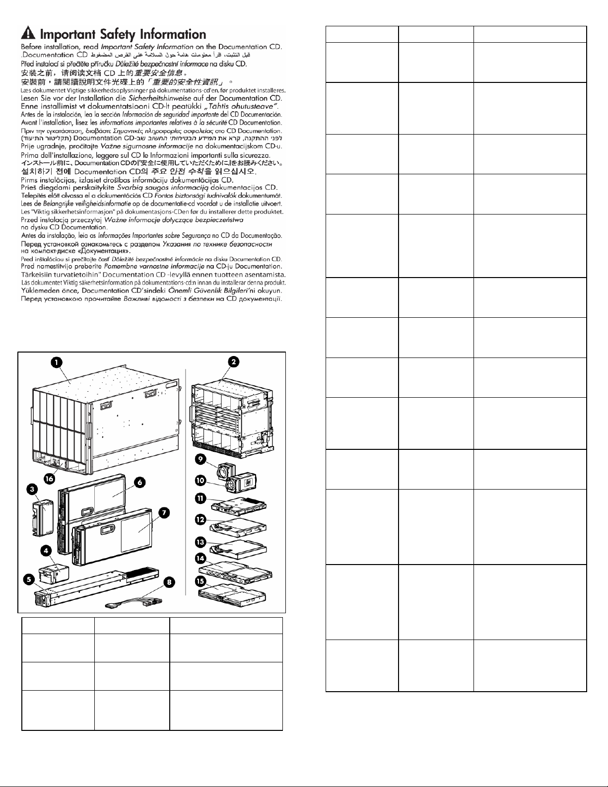
Verifying the pallet contents
Item Name Description
1 HP BladeSystem
c7000 Enclosure
2 Rear cage The rear section of the
3 Device bay blank A mandatory insert
The HP BladeSystem
enclosure
enclosure
installed in any unused
device bay
Item Name Description
4 Power supply
blank
A mandatory insert
installed in any unused
power supply bay
5 Enclosure hot-
plug power
The power supply for the
enclosure
supply (quantity
as ordered)
6 Full-height device
(quantity as
The full-height server or
storage blade
ordered)
7 Half-height
device (quantity
The half-height server or
storage blade
as ordered)
8 Local I/O cable A cable with serial, USB,
and video connectors that
connects to the I/O
connector on the front of a
blade
9 Fan blank A mandatory insert
installed in any unused fan
bay
10 HP Active Cool
Fan (quantity as
ordered)
11 Onboard
Administrator
module
12 Onboard
Administrator
blank
A fan used to cool the
components installed in the
enclosure
An optional module used to
manage the components
installed in the enclosure
A mandatory cover
installed in any unused
Onboard Administrator
bay
13 Interconnect
blank
A mandatory insert
installed in any unused
interconnect bay
14 Interconnect
module (quantity
and type as
ordered)
Any of several
components, such as pass-
throughs or switches that
enable communication
between the blade and the
enclosure
15 Onboard
Administrator tray
A tray that contains the
entire management
subsystem of the enclosure
(this tray should be
removed only by a
qualified technician)
16 HP BladeSystem
Insight Display
A display that provides
information about the
health and operation of the
enclosure
Page 3
Item Name Description
17* Power retention
ties (single-phase
enclosures only;
in the bag, taped
Tie straps that help prevent
single-phase power cables
from disconnecting from
the power connectors
to the top of the
enclosure)
18* Documentation
CD
The CD containing detailed
documentation on using the
enclosure
19* SmartStart CD A CD containing
SmartStart software, a
collection of software that
optimizes single-server
setup
20* Hard copy
installation
The printed installation
instructions
instructions for
blades, options
and interconnects
21* Installation
checklist
A checklist to guide you
through installation of the
enclosure and its
components
* Not shown
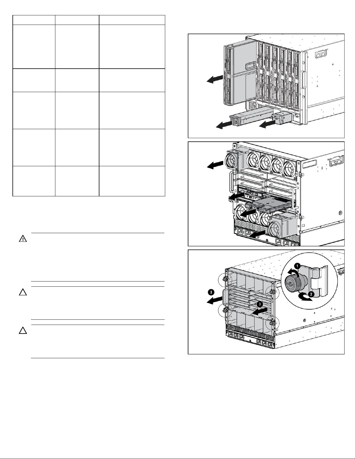
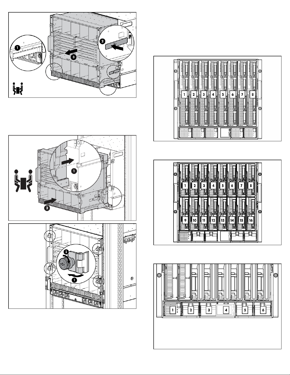
2. Remove all components from the front and rear of the
enclosure, and then remove the rear cage.
Installing the enclosure
WARNING: Because the fully-populated enclosure
can weigh up to 217.7 kg (480 lb), remove all
components and the rear cage from the enclosure
before removing the enclosure from the pallet to
reduce the risk of personal injury when moving the
enclosure.
CAUTION: When removing the rear cage and
midplane assembly, the connectors on the midplane
assembly are susceptible to damage. Use caution to
avoid damage to the pins and connectors.
CAUTION: Be sure the hinges are completely open
before installing the rear cage into the enclosure.
Failure to do so can cause damage to pins and
connectors.
1. The enclosure can be installed in a rack or rack-free
environment. Select the proper location based on
requirements detailed in the HP BladeSystem c7000
Enclosure Setup and Installation Guide.
Page 4
3. (Optional) Install the enclosure into a rack. See the HP
BladeSystem c7000 Enclosure Rack Template. For rack-
free installations, omit this step.
4. Install the rear cage into the enclosure, close the hinges,
and tighten the thumbscrews.
Enclosure bay identification
Before installing front or rear components into the enclosure,
review enclosure bay numbering for each component.
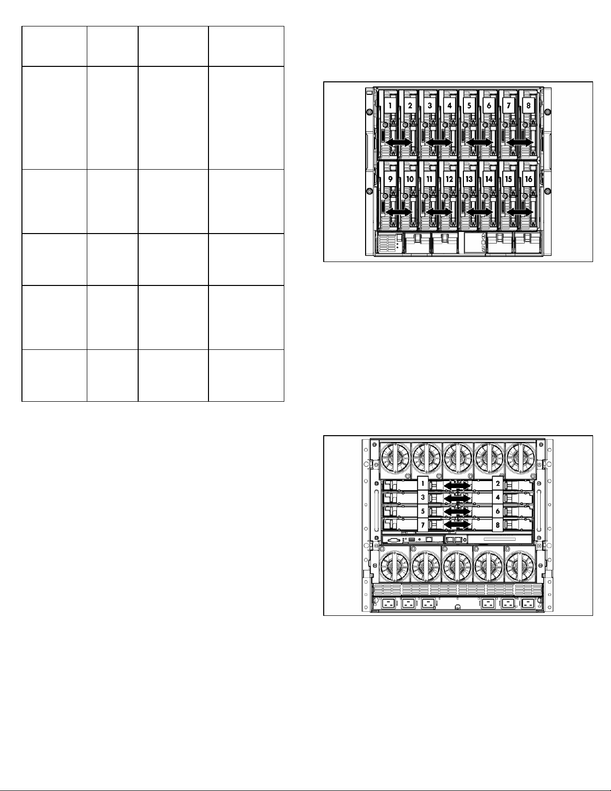
Full-height device bay numbering
Half-height device bay numbering
Power supply bay numbering
Page 5

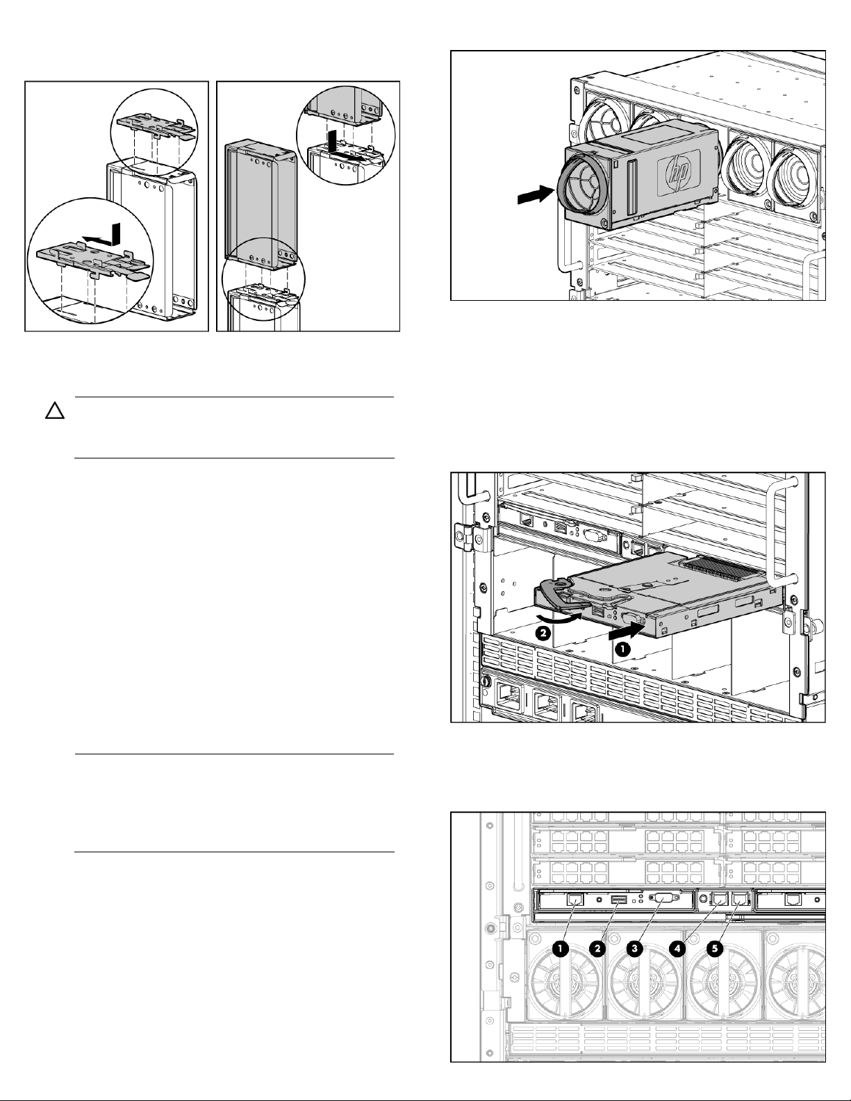
Fan bay numbering
g
1. Add any ordered options to each server blade:
o Additional processor
Installing the front components
CAUTION: To prevent improper coolin
damage, do not operate the enclosure unless all
bays are populated with a component or a blank.
1. Install the power supplies based on the total number of
supplies needed:
o Two power supplies: Bays 1 and 4
o Three power supplies: Bays 1, 2, and 4
o Four power supplies: Bays 1, 2, 4, and 5
o Five power supplies: Bays 1, 2, 3, 4, and 5
o Six power supplies: One in each bay
Install power supply blanks in any unused power supply
bays.
Power supplies are installed in this manner to provide
maximum flexibility for redundancy and three-phase
configuration options. To calculate how many power
supplies are needed, see the HP power calculator
(http://www.hp.com/go/bladesystem/powercalculator
NOTE: This document discusses installation of AC
power supplies only. For information on configuring
DC power supplies or HP Carrier Grade Solutions,
see the documentation that came with your power
supply.
NOTE: Slide the HP BladeSystem Insight Display to
the right or left to gain access to all power supply
bays.
and thermal
o Additional memory
o Mezzanine option cards
2. (Optional) If you are installing a full-height device,
remove the half-height device bay shelf. If you are
installing a half-height device, omit this step.
).
3. Remove the connector covers.
4. Install the server or storage blades.
5. Install device bay blanks into any unused device bays.
Page 6
g
g
If the empty bays are configured for a full-height device,
join two device bay blanks to create a full-height blank.
Installing the rear components
CAUTION: To prevent improper coolin
damage, do not operate the enclosure unless all
bays are populated with a component or a blank.
and thermal
2. Install fan blanks in any unused fan bays.
3. Install the Onboard Administrator modules into the
Onboard Administrator tray based on the total number
ordered:
o One Onboard Administrator module: Bay 1
o Two Onboard Administrator modules: Bays 1 and 2
Install an Onboard Administrator blank into any unused
Onboard Administrator bay.
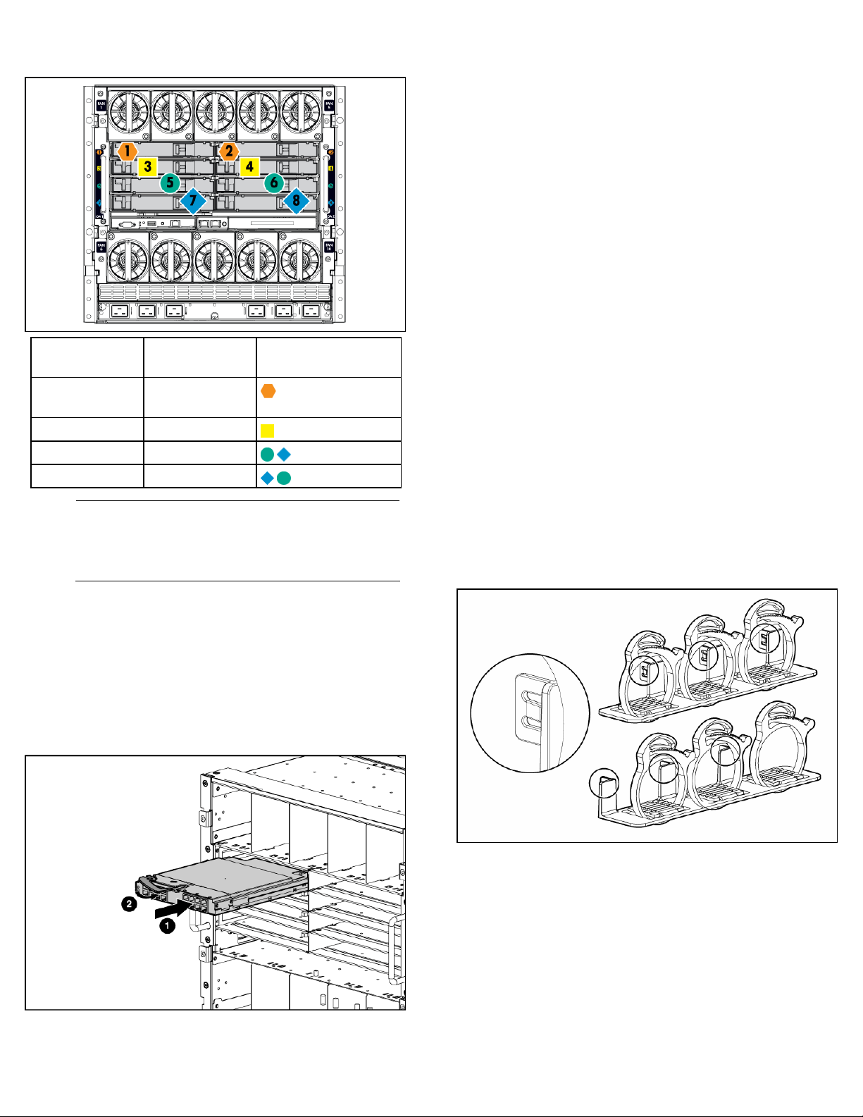
1. Install fans in even-numbered groups, based on the total
number of blades installed in the enclosure:
o Four fan configuration—Fan bays 4, 5, 9, and 10
are used to support a maximum of two devices
located in device bays 1, 2, 9, or 10. Only two
device bays can be used with four fans.
o Six fan configuration—Fan bays 3, 4, 5, 8, 9, and
10 are used to support devices in device bays 1, 2,
3, 4, 9, 10, 11, or 12.
o Eight fan configuration—Fan bays 1, 2, 4, 5, 6, 7,
9, and 10 are used to support devices in all device
bays.
o Ten fan configuration—All fan bays are used to
support devices in all device bays.
NOTE: When installing a fan in the top row of fan
bays, orient the fan so that the LED is in the lower
ht corner. When installing a fan in the bottom row
ri
of fan bays, orient the fan so the LED is in the upper
left corner.
Connecting the cables
1. Identify all connectors.
Page 7

Item Connector Description
1 OA/iLO Onboard Administrator Ethernet connection.
Use a CAT5 patch cable to connect to the
management network. This is the connector for
the IP address of the Onboard Administrator
and for the iLO ports on each server blade.
2 USB For future USB connections. Not currently
supported.
3 Serial
connector
Used for command line interface (CLI). Connects
to a laptop or computer with a null-modem
serial cable (RS232).
4 Enclosure
link-down
Connects to the enclosure link-up port on the
enclosure below with a CAT5 patch cable.
port
5 Enclosure
link-up
port and
service
port
Connects to the enclosure link-down port on the
enclosure above with a CAT5 patch cable. On
a stand-alone enclosure or the top enclosure in
a series of linked enclosures, the top enclosure
link-up port functions as a service port.
2. Connect a standard CAT5 patch cable to the OA/iLO
port of each installed Onboard Administrator module to
connect to the management network.
Mapping to interconnect ports
Several port types are referenced in the following tables.
• Examples of 1x ports are 1-Gb Ethernet (1 GbE) switch
modules and Fibre Channel interconnect modules.
• An example of a 2x port is a Serial Attached SCSI (SAS)
interconnect module. (Reserved for future use.)
• Examples of 4x ports are 10-Gb Ethernet (10 GbE)
interconnect modules.
NOTE: 1x and 2x port mezzanine cards interface
with single-wide interconnect modules. 4x port
mezzanine cards interface with double-wide
interconnect modules.
The term "1x/2x" refers to the number of interconnect lanes
per port provided by the controller. The more lanes provided
per port, the higher the data transmission rate coming from
that port.
Mapping half-height blades
3. If more than one enclosure is installed in the rack, use a
CAT5 patch cable to connect the enclosure link-down
port on the upper enclosure to the enclosure link-up port
on the lower enclosure.
NOTE: The enclosure link ports are designed only to
support c-Class enclosures in the same rack. The
enclosure link-up port on the top enclosure is the
service port, and the enclosure link-down port on the
bottom linked enclosure is unused.
NOTE: The HP BladeSystem c-Class enclosure link
ports are not compatible with the HP BladeSystem
p-Class enclosure link ports.
Page 8

The following table lists the available configurations for halfheight devices installed in device bay N (1–16).
Connection Port number Connects to
interconnect
bay/port
Embedded
NIC
Mezzanine
slot 1—1x or
2x cards
Mezzanine
NIC 1
NIC 2
1x/2x port 1
1x/2x port 2
1/Port N
2/Port N
3/Port N
4/Port N
4x port 1 3/Port N • One doubleslot 1—4x
cards
Mezzanine
slot 2—1x or
2x cards
Mezzanine
slot 2—4x
cards
1x/2x port 1
1x/2x port 2
1x/2x port 3
1x/2x port 4
4x port 1
4x port 2
5 / port N
6 / port N
7 / port N
8 / port N
5/Port N
7/Port N
* Connectivity to interconnect bays 7 and 8 is only available with
four-port mezzanine cards or port 2 of 4x card in Mezzanine slot 2.
Comments
One or two
single-wide
Ethernet
interconnect
modules
• One single-
wide
interconnect
module
• Four port
cards will
only connect
the first two
ports.
wide
interconnect
module
• Only port 1
of a two port
card will be
connected.
One or two
single-wide
interconnect
modules
One or two
double-wide
interconnect
modules
Mapping full-height blades
The following table lists the available configurations for fullheight devices installed in device bay N (1–8).
Connection Port
number
Connects to
interconnect
bay/port
NIC NIC 1
NIC 2
NIC 3
NIC 4
Mezzanine
slot 1—1x or
2x cards
1x/2x port
1
1x/2x port
2
1x/2x port
1/Port N+8
2/Port N+8
1/Port N
2/Port N
3/Port N
4/Port N
3/Port N+8
4/Port N+8
3
1x/2x port
4
Comments
One or two
single-wide
Ethernet
interconnect
modules
One or two
single-wide
interconnect
modules
Page 9
Connection Port
number
Mezzanine
slot 1—4x
cards
Mezzanine
slot 2—1x or
2x cards
Mezzanine
slot 2—4x
cards
Mezzanine
slot 3—1x or
2x cards
Mezzanine
slot 3—4x
cards
* Connectivity to interconnect bays 7 and 8 is only available with
four-port mezzanine cards or port 2 of 4x card in Mezzanine slot 2.
4x port 1 3/Port N • One double-
1x/2x port 1
1x/2x port 2
1x/2x port 3
1x/2x port 4
4x port 1
4x port 2
1x/2x port 1
1x/2x port 2
1x/2x port 3
1x/2x port 4
4x port 1
4x port 2
Connects to
interconnect
bay/port
5/Port N
6/Port N
7/Port N+8
8/Port N+8
5/Port N
7/Port N
7/Port N
8/Port N
5/Port N+8
6/Port N+8
5/Port N
7/Port N
Comments
wide
interconnect
module
• Only port 1
of a two port
card will be
connected
Up to four singlewide interconnect
modules
One or two
double-wide
interconnect
modules
Up to four singlewide interconnect
modules
One or two
double-wide
interconnect
modules
Device bay crosslinks
Device bay crosslinks are wired between adjacent horizontal
device bay pairs.
For half-height blades, these signals connect a four-lane PCIe
module to a partner blade such as a tape blade or a PCI
expansion blade. For full-height blades, these signals are used
to connect a PCIe module to a partner blade in the lower
adjacent bay and require a PCIe pass-thru mezzanine card
installed in mezzanine connector 3. The Onboard
Administrator disables the device bay crosslinks when they
cannot be used, such as when two server blades reside in
adjacent device bays.
Interconnect bay crosslinks
Interconnect bay crosslinks are wired between adjacent
interconnect bay pairs.
Bay-to-bay crosslinks
Four trace SerDes signals between adjacent bays are
provided in the enclosure midplane to permit bay-to-bay
communications. Interconnect modules can only connect
horizontally.
You can enable these signals to provide module-to-module
connections, such as Ethernet crosslink ports between
matching switches, or Virtual Connect modules as stacking
links. Onboard Administrator disables the interconnect bay
crosslinks when they cannot be used, such as when two
different modules reside in adjacent horizontal interconnect
bays.
Page 10
Installing interconnect modules
Server blade
signal
NICs 1, 2, 3, and
4 (embedded)
Mezzanine 1 3, 4
Mezzanine 2 5, 6 and then 7, 8
Mezzanine 3 7, 8 and then 5, 6
NOTE: For information on the location of LEDs and
ports on individual interconnect modules, see the
documentation that ships with the interconnect
module.
Interconnect bay
number
1, 2
Interconnect bay label
3. Connect each installed interconnect module to the
external connections with the appropriate cable.
Powering up the enclosure
Single-phase power configuration
For a single phase power configuration:
1. Connect the AC power cables to the power connectors
on the rear of the enclosure corresponding to the power
supply that was populated on the front of the enclosure.
2. Be sure each power cable is securely attached to the
power connectors.
3. Connect the AC power cables to the AC power source
or to an installed power distribution unit (PDU).
4. Turn on the AC circuit breakers that power the power
cables installed in the enclosure.
5. Locate the power retention bracket that came with the
enclosure.
6. Verify that the power cord retention tabs are on the
correct side.
o On the left side: To install the power cord retention
bracket on the left side of the enclosure, ensure the
power cord retention tabs are located to the right of
the snap clamps.
o On the right side: To install the power cord retention
bracket on the right side of the enclosure, ensure the
power cord retention tabs are located on the left side
of the snap clamps.
1. Install the interconnect modules based on the number
ordered and the number of fabrics in the configuration.
The enclosure ships with interconnect bay dividers
installed. The interconnect bay dividers must be removed
before installing double-wide interconnect modules. To
remove an interconnect bay divider, press the release
tab, and pull the interconnect bay divider out of the
enclosure.
2. Install interconnect blanks in any unused interconnect
bays.
7. Place the power cord retention bracket under the power
cords, and then align the power cords with the snap
clamps.
8. Open the snap clamps, and then insert each power cord
inside each clamp.
9. Slide the power cord retention bracket until the bracket
touches the enclosure.
Page 11

Insert the power cord retention tabs into the slots on the
10.
enclosure until they snap into place.
11. Slide each snap clamp over the end of each power cord
overmold, and then squeeze each snap clamp closed.
To set up an enclosure with network connectivity to the
Onboard Administrator:
1. On the Enclosure Settings screen, confirm the default
settings.
o Use the navigation arrows to navigate to a particular
setting, and press OK.
o Navigate to the "?" box next to a setting and press
OK to get help on that setting.
2. Confirm the Redundancy mode, which is typically AC
Redundant, for the power supplies.
3. Set the Limit AC Input VA if the facility must limit AC
power to the enclosure below what the power supplies
can draw.
4. Enable Dynamic Power Savings to provide the highest
power efficiency without affecting server performance.
5. Write down the OA1 and OA2 (if present) IP address.
This information is needed when deploying the
management software.
o If the OA1 or OA2 IP address is 0.0.0.0., set the
address. Navigate to the address and press OK. Use
the up and down arrows to select Static IP address.
Use the up and down arrows on each field to set the
IP, netmask and gateway one octet at a time. Press
OK when done, and then press OK again on Accept
to confirm the new IP address settings.
Three-phase power configuration
For a three-phase power configuration, the AC power cables
are already attached to the enclosure. To cable the enclosure
using a three-phase AC configuration:
1. Connect the AC power cables to the AC power source.
2. Turn on the AC circuit breakers that power the power
cables installed in the enclosure.
Setting up the HP BladeSystem Insight Display
When the enclosure is powered up for the first time, the
Insight Display launches an installation wizard to guide you
through the configuration process. After configuring the
enclosure, the Insight Display verifies that there are no
installation or configuration errors.
o If the address is not 0.0.0.0., record the displayed
address to use for remote login to the Onboard
Administrator over the management network.
6. (Optional) Edit the Enclosure Name. The default value is
the Onboard Administrator serial number.
7. (Optional) Edit the Rack Name. The default value is
UnnamedRack.
8. Set the Insight Display PIN to prevent other users of the
LCD from changing the settings.
9. Navigate to Accept at the bottom of the Enclosure
Settings, and press OK to Accept all the settings to
continue. If you are setting up a single enclosure,
proceed to step 11.
To identify the enclosure, the rear enclosure UID light and the
background of the Insight Display are illuminated blue when
the enclosure is powered on initially.
Page 12
J
Navigate to Accept, and press OK to apply the
10.
Enclosure Settings (Redundancy Mode, Limit AC, Power
Savings, Rack Name, and Insight Display PIN) to other
linked enclosures.
11. Follow the instructions on the next screen.
13. Open a browser and connect to the active Onboard
Administrator module using the Onboard Administrator
IP address that was configured during the Insight Display
installation wizard process.
14. Enter the user name and password from the tag supplied
with the Onboard Administrator module to access the
remote Onboard Administrator web interface and
complete the Onboard Administrator first time installation
wizard.
To set up the enclosure without network connectivity to the
Onboard Administrator, see the HP BladeSystem Onboard
Administrator User Guide.
The installation is complete.
For more information
For more detailed setup and configuration information, see
the HP BladeSystem c-Class Solution Overview and the HP
BladeSystem c7000 Enclosure Setup and Installation Guide.
You can also find information on the HP website
(http://www.hp.com/go/bladesystem/documentation
).
12. Follow the instructions on the next screen.
© Copyright 2006, 2008 Hewlett-Packard Development Company, L.P.
The information contained herein is subject to change without notice. The only
warranties for HP products and services are set forth in the express warranty
statements accompanying such products and services. Nothing herein should
be construed as constituting an additional warranty. HP shall not be liable for
technical or editorial errors or omissions contained herein.
Part Number 411762-005
uly 2008 (Fifth Edition)
 Loading...