

Page 1

HP BladeSystem c3000 Enclosure
Quick Setup Instructions
Part Number 446990-002
August 2008 (Second Edition)
Page 2
Site requirements
Select an installation site that meets the detailed installation site
requirements described in the server user guide on the
Documentation CD.
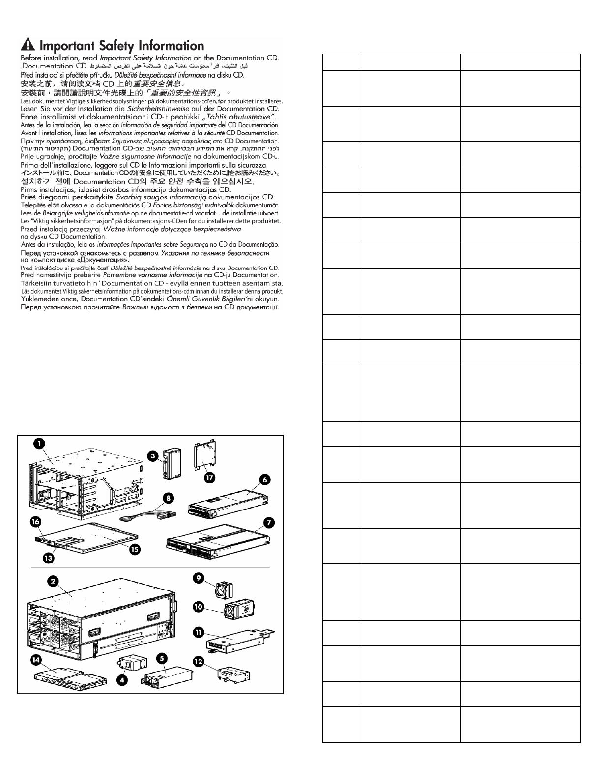
Pallet contents
Item Name Description
1
2
3 Device bay blank
4 Power supply blank
5
6
7
8 Local I/O cable
9 Fan blank
10
11
12 KVM module blank
13 Insight Display
14
15
16
17 DVD drive
18*
19* Interconnect blank
20* Documentation CD
HP BladeSystem c3000
Enclosure front cage (front
view)
HP BladeSystem c3000
Enclosure chassis (rear
view)
Power supply (quantity as
ordered)
Half-height device (quantity
as ordered)
Full-height device (quantity
as ordered)
HP Active Cool fan
(quantity as ordered)
Enclosure/Onboard
Administrator link module
Interconnect module
(quantity and type as
ordered)
Onboard Administrator
tray
Onboard Administrator
module
Onboard Administrator
blank
The HP BladeSystem enclosure
front cage as viewed from the
front
The HP BladeSystem enclosure
chassis as viewed from the rear
A mandatory insert installed in
any unused device bay
A mandatory insert installed in
any unused power supply bay
The power supply for the
enclosure
A half-height server or storage
blade
A full-height server or storage
blade
A cable with serial, USB, and
video connectors that attaches to
the I/O connector on the front of
a blade
A mandatory insert installed in
any unused fan bay
A fan that cools the components
installed in the enclosure
The module that provides
enclosure-link connectivity and
Onboard
Administrator/iLO/interconnect
management access
A mandatory cover installed in
the KVM module bay
A display that provides
information about the health and
operation of the enclosure
Components, such as pass-thrus
or switches, that enable
communication between the
blade and the enclosure
A removable tray that houses the
Onboard Administrator module
and Insight Display
The module that manages the
components installed in the
enclosure. Built into the Onboard
Administrator tray for a single
Onboard Administrator.
An optional DVD drive for the
enclosure
A mandatory cover installed in
any unused Onboard
Administrator bay
A mandatory insert installed in
any unused interconnect bay
A CD containing detailed
documentation about using the
enclosure
Page 3
Item Name Description
21* SmartStart CD
22*
Printed installation
instructions for blades,
options, and interconnects
23* Installation checklist
* Not shown
A CD containing SmartStart
software, a collection of software
that optimizes single-server setup
The printed installation
instructions
A checklist that guides you
through installation of the
enclosure and its components
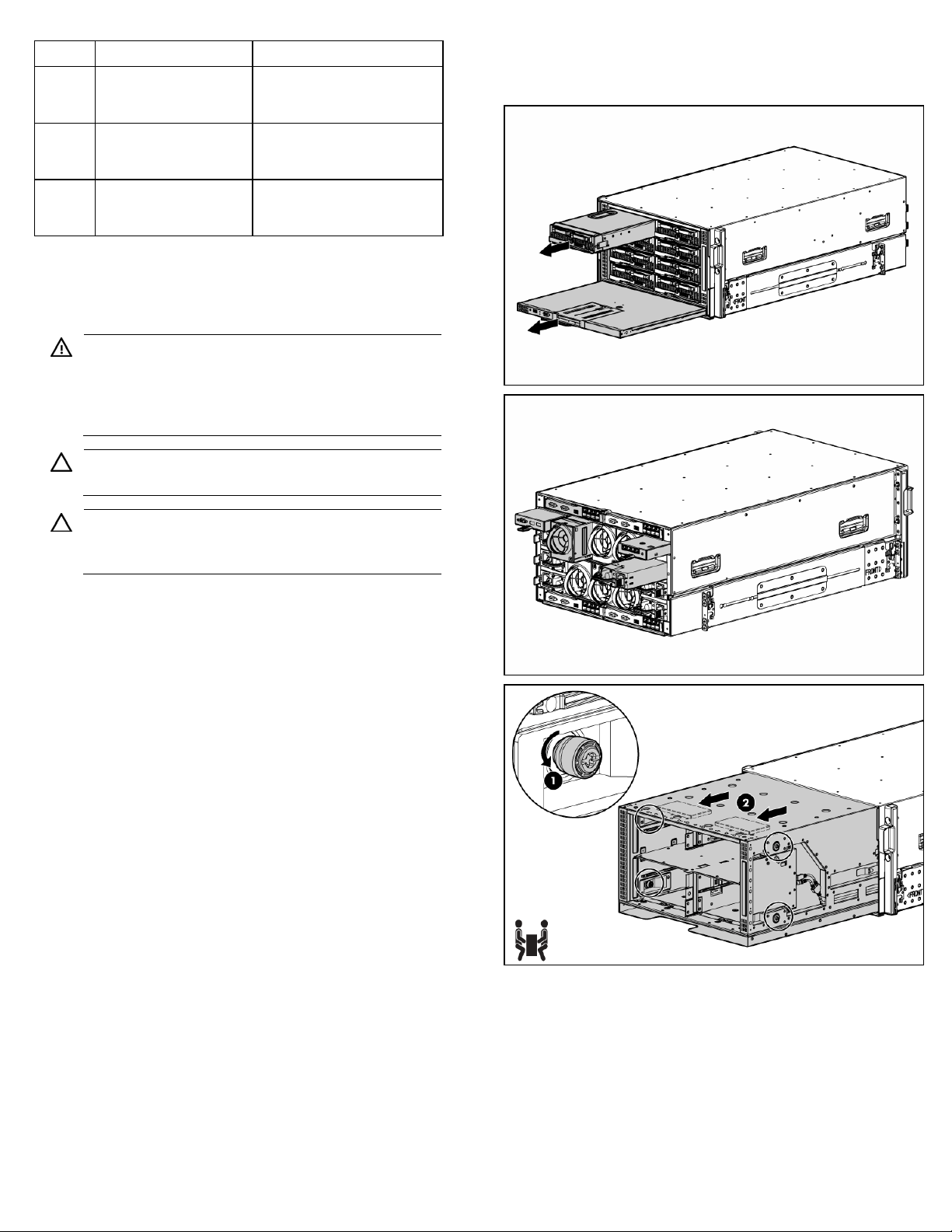
Installing the enclosure
WARNING: Because the fully-populated enclosure can
weigh up to 131.5 kg (290 lb), remove all components
and the front cage from the enclosure before removing the
enclosure from the pallet to reduce the risk of personal
injury when moving the enclosure.
CAUTION: Do not touch or bump front cage connector
pins when installing the front cage into the enclosure.
CAUTION: Be sure the hinges are completely open
before installing the front cage into the enclosure. Failure
to do so can cause damage to pins and connectors.
1. The enclosure can be installed in a rack or rack-free
environment. Select the proper location based on requirements
detailed in the HP BladeSystem c3000 Enclosure Setup and
Installation Guide.
2. With the enclosure still on the pallet, remove all components
from the front and rear of the enclosure, and then remove the
front cage.
Page 4
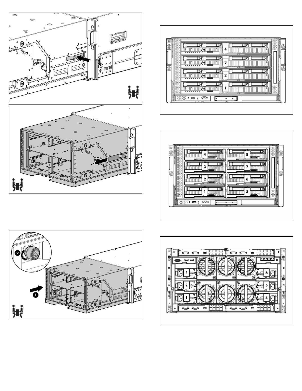
Full-height device bay numbering
3. (Optional) Install the enclosure into a rack. See the HP
BladeSystem c3000 Enclosure Rack Template. For rack-free
installations, omit this step.
4. Install the front cage into the enclosure, then tighten the
thumbscrews.
Half-height device bay numbering
Power supply bay numbering
Enclosure bay identification
Before installing front or rear components into the enclosure, review
enclosure bay numbering for each component.
Page 5
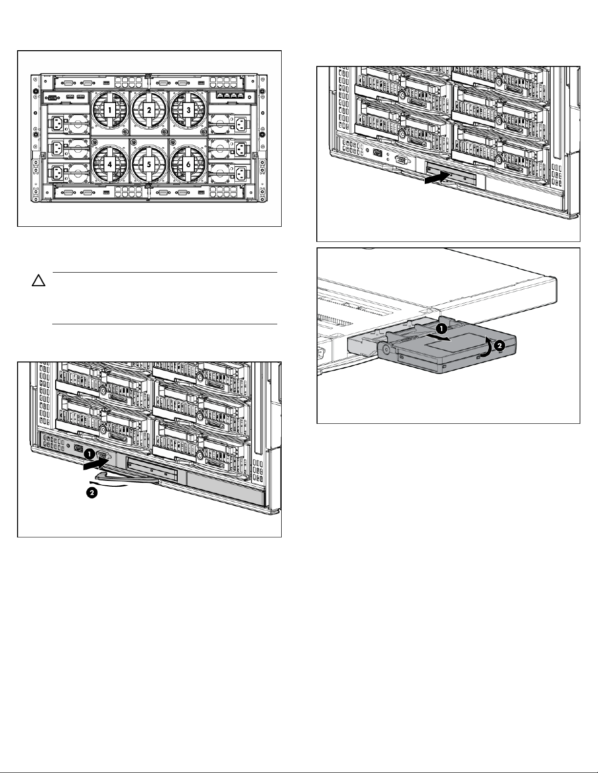
Fan bay numbering
Installing the front components
CAUTION: To prevent improper cooling and thermal
damage, do not operate the blade or the enclosure unless
all hard drive and device bays are populated with either a
component or a blank.
1. Slide the Onboard Administrator module into the bay. When
fully inserted, the device locks into place.
2. Press and release the panel to access the Insight Display. Pull
the Insight Display out of the chassis to lock it into place, then
tilt it for viewing.
3. Add any ordered options to each server blade
o Additional processor
o Additional memory
o Mezzanine option cards
4. (Optional) If you are installing a full-height device, remove the
half-height divider. If you are installing a full-height device in
bays 3/7 and two half-height devices in bays 4/8, install the
mini divider. If you are installing a half-height device, omit this
step.
Page 6

To remove the half-height divider:
To install the mini divider:
5. Remove the connector covers.
6. Install the server or storage blades.
NOTE: If you plan to install four HP Active Cool Fans, you
can install up to two full-height blades or up to four halfheight blades. For full-height blades, populate device bay
1 first, then device bay 2. For half-height blades, populate
the device bays in the following order: 1, 2, 5, 6.
If you plan to install six HP Active Cool Fans, blades can
be installed in any configuration.
7. Install device bay blanks into any unused device bays.
Page 7

If the empty bays are configured for a full-height device, join
two device bay blanks to create a full-height blank.
2. (Optional) Slide the c3000 KVM module into the bay. When
fully inserted, the device locks into place.
Installing the rear components
CAUTION: To prevent improper cooling and thermal
damage, do not operate the enclosure unless all bays are
populated with a component or a blank.
1. Slide the fan into the enclosure until it locks in place.
NOTE: The HP BladeSystem c3000 Enclosure is shipped
with four HP Active Cool fans and supports up to six fans.
Install fans based on the number of blades installed:
• For one to four half-height blades or one to two full-
height blades, install four fans in bays 2, 4, 5, and 6.
• For additional blades, install six fans using all bays.
NOTE: When installing a fan in the top row of fan bays,
orient the fan so that the LED is in the lower right corner.
When installing a fan in the bottom row of fan bays,
orient the fan so the LED is in the upper left corner.
3. Slide the power supply into the power supply bay until the
device locks into place.
WARNING: A risk of electric shock from high leakage
current exists. Before connecting the AC supply to the
power enclosures, be sure that the electrical outlets are
properly grounded (earthed).
When installed in a rack, the enclosure must be used with
an internal rack mount power distribution unit (PDU) or
uninterruptible power supply (UPS) that uses an industrial
style wall plug (for example, locking type NEMA or IEC
309 pin and sleeve configuration) which insures a reliable
protective earth ground connection.
When installed in a rack-free environment, the area must
be designated as a restricted access area, and the
enclosure must be used with a dedicated uninterruptible
power supply (UPS) that uses an industrial style wall plug
(for example, locking type NEMA or IEC 309 pin and
sleeve configuration) which insures a reliable protective
earth ground connection.
Installation and maintenance must be performed by
trained service personnel.
Page 8

NOTE: When installing a power supply in power supply
bay 1, 2, or 3, orient the power supply so the plug is on
the left side. When installing a power supply in power
supply bay 4, 5, or 6, orient the power supply so the plug
is on the right side.
For AC redundant (N+N power supplies) configurations, an
even number of power supplies is required. For this
configuration, where N is the number of power supplies being
used, populate the power supply bays as shown.
N + N Populate the following power supply bays
1 + 1 1 and 4
2 + 2 1, 2, 4, and 5
3 + 3 Populate all bays
For power supply redundant (N+1 power supplies)
configurations, where N is the number of power supplies being
used, populate the power supply bays as shown.
N + 1 Populate the following power supply bays
1 + 1 1 and 4
2 + 1 1, 4, and 2
3 + 1 1, 4, 2, and 5
4 + 1 1, 4, 2, 5, and 3
5 + 1 Populate all bays
4. Slide the enclosure/Onboard Administrator link module into
the bay until the device locks into place.
Connecting the cables
1. Identify all connectors.
Item Connector Description
Enclosure
1
link-down
port
Enclosure
2
link-up port
and
service
port
3 OA1/iLO
4 OA2/iLO
Connects to the enclosure link-up port on the enclosure
beneath it with a CAT5 patch cable.
Connects to the enclosure link-down port on the
enclosure above it with a CAT5 patch cable. On a
stand-alone enclosure or the top enclosure in a series
of linked enclosures, the top enclosure link-up port
might function as a service port.
Onboard Administrator Ethernet connection. Use a
CAT5 patch cable to connect to the management
network. Connect to this port to remotely communicate
with the Onboard Administrator, all iLO ports on each
blade, and supporting interconnect module
management parts.
Is reserved for future Onboard Administrator
connections.
Page 9

2. Connect the management network with a standard CAT5 patch
cable.
NOTE: If more than one enclosure is installed in the rack,
use a CAT5 patch cable to connect the enclosure linkdown port on the upper enclosure to the enclosure link-up
port on the lower enclosure.
3. Connect the management link cable between c-Class
enclosures in the same rack.
Mapping half-height blades
NOTE: The enclosure link ports are designed only to
support c-Class enclosures in the same rack. The enclosure
link-up port on the top enclosure is the service port, and
the enclosure link-down port on the bottom linked
enclosure is unused.
NOTE: The HP BladeSystem c-Class enclosure link ports
are not compatible with the HP BladeSystem p-Class
enclosure link ports.
Mapping to interconnect ports
Several port types are referenced in the following tables.
• Examples of 1x ports are 1-Gb Ethernet (1 GbE) switch
modules and Fibre Channel interconnect modules.
• An example of a 2x port is a Serial Attached SCSI (SAS)
interconnect module. (Reserved for future use.)
• Examples of 4x ports are 10-Gb Ethernet (10 GbE)
interconnect modules.
NOTE: 1x and 2x port mezzanine cards interface with
single-wide interconnect modules. 4x port mezzanine
cards interface with double-wide interconnect modules.
The term "1x/2x" refers to the number of interconnect lanes per port
provided by the controller. The more lanes provided per port, the
higher the data transmission rate coming from that port.
The following table lists the available configurations for half-height
devices installed in device bay N (1–8)
Connection Port number Connects to
Comments
interconnect
bay/port
Embedded NIC NIC 1
NIC 2
Mezzanine slot
1—1x or 2x
cards (4x cards
are not
supported in this
slot)
1x/2x port 1
1x/2x port 2
1/Port N
1/Port N+8
2/Port N
2/Port N+8
One single-wide
Ethernet
interconnect
module
• One single-
wide
interconnect
module
• Only two
ports will be
connected.
• Four port
cards will
only connect
the first two
ports.
Mezzanine slot
2—1x or 2x
cards
1x/2x port 1
1x/2x port 2
1x/2x port 3
1x/2x port 4
3/Port N
4 Port N
3/Port N+8
4/Port N+8
One or two single-
wide interconnect
modules
Page 10

Connection Port number Connects to
interconnect
bay/port
Mezzanine slot
2—4x cards
4x port 1
4x port 2
3/Port N
3/Port N+8
Mapping full-height blades
Comments
One double-wide
interconnect
module
Connection Port
number
Connect to
interconnect
Comments
bay/port
Mezzanine slot
2—4x cards
Mezzanine slot
3—1x or 2x
cards
Mezzanine slot
3—4x cards
4x port 1
4x port 2
1x/2x port 1
1x/2x port 2
1x/2x port 3
1x/2x port 4
4x port 1
4x port 2
3/Port N
3/Port N+8
3/Port N+12
4/Port N+12
3/Port N+4
4/Port N+4
3/Port N+12
3/Port N+4
One double-wide
interconnect module
One or two singlewide interconnect
modules
One double-wide
interconnect module
Mapping BL2x220c blades
The following table lists the available configurations for full-height
devices installed in device bay N (1–4)
Connection Port
number
Connect to
interconnect
Comments
bay/port
Embedded NIC NIC 1
NIC 2
NIC 3
NIC 4
Mezzanine slot
1—1x or 2x
cards (4x cards
are not supported
in this slot)
Mezzanine slot
2—1x or 2x
cards
1x/2x port 1
1x/2x port 2
1x/2x port 3
1x/2x port 4
1x/2x port 1
1x/2x port 2
1x/2x port 3
1x/2x port 4
1/Port N+4
1/Port N+12
1/Port N
1/Port N+8
2/Port N
2/Port N+8
2/Port N+4
2/Port N+12
3/Port N
4/Port N
3/Port N+8
4/Port N+8
One single-wide
Ethernet interconnect
module
One single-wide
interconnect module
One or two singlewide interconnect
modules
Page 11

To support network connections for specific signals, install an
interconnect module in the bay corresponding to the embedded NIC
or mezzanine signals.
Connection Port number Connects to
Comments
interconnect
bay/port
Embedded
NIC
Mezzanine
slot 1—1x,
2x, or 4x
cards
Server A: NIC 1
Server A: NIC 2
Server B: NIC 1
Server A: Mezz
port 1
Server A: Mezz
port 2
Server B: Mezz
port 1
Server B: Mezz
port 2
1/Port N
2/Port N
1/Port N+8
2/Port N+8
3/Port N
4/Port N
3/Port N+8
4/Port N+8
Two single-wide
Ethernet
interconnect
modules
• Two single-
wide
modules or
one doublewide
interconnect
module
• Only two
ports will be
connected.
• Four port
cards will
only
connect the
first two
ports.
crosslinks in instances where they cannot be used, such as when two
blades reside in adjacent device bays.
Interconnect bay crosslinks
Interconnect bay crosslinks are wired between adjacent interconnect
bay pairs.
You can enable these signals to provide module-to-module
connections. The Onboard Administrator disables the interconnect
bay crosslinks in instances where the crosslinks cannot be used, such
as when two different modules reside in adjacent horizontal
interconnect bays.
Bay-to-bay crosslinks
For bay-to-bay communication, the enclosure midplane provides fourtrace SerDes signals between adjacent bays.
Device bay crosslinks
Device bay crosslinks are wired between adjacent horizontal device
bay pairs.
For half-height blades, these signals are used to connect a four-lane
PCIe module to a partner blade such as a tape blade or a PCI
expansion blade. For full-height blades, these signals are used to
connect a PCIe module to a partner blade in the lower adjacent bay
and require a PCIe pass-thru mezzanine card installed in mezzanine
connector 3. The Onboard Administrator disables the device bay
Installing interconnect modules
Server blade
signal
Interconnect
bay number
Interconnect
bay
Notes
label
NICs 1, 2, 3,
and 4
(embedded)
Mezzanine 1 2
1
—
Four port cards connect
to bay 2
Page 12

Server blade
signal
Interconnect
bay number
Interconnect
bay
Notes
label
Mezzanine 2 3,4
• Four port cards
• Ports 1 and 3
connect to bay 3
• Ports 2 and 4
connect to bay 4
Mezzanine 3 3,4
• Four port cards
• Ports 1 and 3
connect to bay 3
• Ports 2 and 4
connect to bay 4
NOTE: For information on the location of LEDs and ports
on individual interconnect modules, see the documentation
that ships with the interconnect module.
1. Install the interconnect modules based on the quantity ordered
and the number of fabrics in the configuration.
The enclosure ships with interconnect bay dividers installed.
The interconnect bay dividers must be removed before
installing double-wide interconnect modules. To remove an
interconnect bay divider, press the release tab, and pull the
interconnect bay divider out of the enclosure.
2. Install interconnect blanks in any unused interconnect bays.
3. Connect each installed interconnect module to the external
connections with the appropriate cable.
Powering up the enclosure
Setting up the HP BladeSystem Insight Display
When the enclosure is powered up for the first time, the Insight
Display launches an installation wizard to guide you through the
configuration process. After configuring the enclosure, the Insight
Display verifies that there are no installation or configuration errors.
If errors are present, the Insight Display guides you through the
process of correcting the errors.
To identify the enclosure, the rear enclosure UID light and the
background of the Insight Display are illuminated blue when the
enclosure is powered on initially.
To set up an enclosure with network connectivity to the Onboard
Administrator:
1. On the Enclosure Settings screen, confirm the default settings.
o Use the navigation arrows to navigate to a particular
setting, and press OK.
o Navigate to the ? box next to a setting and press OK to get
help on that particular setting.
2. Confirm the Power Mode setting, which defaults to AC
Redundant for the power supplies.
3. If the facility must limit AC power to the enclosure, set the
Power Limit Watts AC below what the power supplies draw.
4. Enable Dynamic Power Savings to provide the highest power
efficiency without affecting server performance.
5. Record the OA1 and OA2 (if present) IP address. This
information is needed when deploying the management
software.
o If the OA1 or OA2 IP address is 0.0.0.0., set the address.
Navigate to the address, and then press OK. Use the up
and down arrows to select Static IP address. Use the up
and down arrows on each field to set the IP, netmask and
gateway one octet at a time. Press OK when done, and
then press OK again on Accept to confirm the new
IP address settings.
o If the address is not 0.0.0.0., record the displayed address
to use for remote login to the Onboard Administrator over
the management network.
6. (Optional) Edit the Enclosure Name. The default value is the
Onboard Administrator serial number.
7. (Optional) Edit the Rack Name. The default value is
UnnamedRack.
8. Set the Insight Display PIN to prevent other users of the LCD
from changing the settings.
1. Connect the power cables to the power supplies.
2. Connect the power cables to the power source or to an
installed PDU.
3. Turn on the AC circuit breakers that power the power cables
installed in the enclosure.
Page 13

9. Navigate to Accept at the bottom of the Enclosure Settings, and
press OK to accept all the settings and continue. If you are
setting up a single enclosure, proceed to step 11.
10. Navigate to Accept, and press OK to apply the Enclosure
Settings (Power Mode, Power Limit, Dynamic Power, Rack
Name, and Insight Display PIN) to other linked enclosures.
12. Follow the instructions on the next screen.
13. Open a browser and connect to the active Onboard
Administrator module using the Onboard Administrator IP
address that was configured during the Insight Display
installation wizard process.
14. Enter the user name and password from the tag supplied with
the Onboard Administrator module to access the remote
Onboard Administrator web interface and complete the
Onboard Administrator first time installation wizard.
11. Follow the instructions on the next screen.
To set up the enclosure without network connectivity to the Onboard
Administrator, see the HP BladeSystem Onboard Administrator User
Guide.
Troubleshooting resources
The HP BladeSystem c-Class Enclosure Troubleshooting Guide
provides procedures and solutions for troubleshooting HP
BladeSystem c-Class enclosures. This guide explains how to use the
Insight Display to troubleshoot enclosures, and it includes a flowchart
to help you navigate the troubleshooting process. To view the guide,
see the HP website
(http://www.hp.com/support/BladeSystem_Enclosure_TSG_en
The installation is complete.
).
For more information
For more detailed setup and configuration information, see the HP
BladeSystem c-Class Solution Overview and the HP BladeSystem
c3000 Enclosure Setup and Installation Guide. You can also find
information on the HP website
(http://www.hp.com/go/bladesystem/documentation
).
Page 14

© Copyright 2007 Hewlett-Packard Development Company, L.P.
The information contained herein is subject to change without notice. The only warranties for HP products and services are set forth in the
express warranty statements accompanying such products and services. Nothing herein should be construed as constituting an additional
warranty. HP shall not be liable for technical or editorial errors or omissions contained herein.
Part Number 446990-002
August 2008 (Second Edition)
 Loading...