

Page 1

Service Reference Guide
HP Blade PC bc1000 and bc1500 Series
5th Edition
This document provides information on spare parts, the removal and
replacement of all parts, as well as information on troubleshooting, POST
error messages, and diagnostic indicator lights.
Document Part Number 352971-005
Page 2

Page 3

Service Reference Guide
HP Blade PC bc1000 and bc1500 Series
5th Edition
Document Part Number: 352971-005
1st Edition (March 2004)
5th edition (May 2007)
May 2007
Page 4

© 2004, 2005, 2006 Hewlett-Packard Development Company, L.P.
HP, Hewlett-Packard, and the Hewlett-Packard logo are trademarks of Hewlett-Packard Company in the U.S. and
other countries.
All other product names mentioned herein may be trademarks of their respective companies.
Hewlett-Packard Company shall not be liable for technical or editorial errors or omissions contained herein or for
incidental or consequential damages in connection with the furnishing, performance, or use of this material. The
information in this document is provided “as is” without warranty of any kind, including, but not limited to, the
implied warranties of merchantability and fitness for a particular purpose, and is subject to change without notice.
The warranties for HP products are set forth in the express limited warranty statements accompanying such
products. Nothing herein should be construed as constituting an additional warranty.
This document contains proprietary information that is protected by copyright. No part of this document may be
photocopied, reproduced, or translated to another language without the prior written consent of Hewlett-Packard
Company.
WARNI NG: Text set off in this manner indicates that failure to follow directions could result in bodily
Å
harm or loss of life.
CAUTION: Text set off in this manner indicates that failure to follow directions could result in damage to
Ä
equipment or loss of information.
Service Reference Guide
HP Blade PC bc1000 and bc1500 Series
1st Edition (March 2004)
5th Edition (May 2007)
Document Part Number: 352971-005
Page 5

Contents
1Spare Parts
1.1 Spare Parts . . . . . . . . . . . . . . . . . . . . . . . . . . . . . . . . . . . . . . . . . . . . . . . . . . . . . . . . . . . . . . . . . . 1–1
2 Removal and Replacement
2.1 Returning the Blade PC . . . . . . . . . . . . . . . . . . . . . . . . . . . . . . . . . . . . . . . . . . . . . . . . . . . . . . . . 2–1
2.2 Removal and Replacement . . . . . . . . . . . . . . . . . . . . . . . . . . . . . . . . . . . . . . . . . . . . . . . . . . . . . 2–1
2.2.1 Powering Down the Blade PC . . . . . . . . . . . . . . . . . . . . . . . . . . . . . . . . . . . . . . . . . . . . . . 2–1
2.2.2 Removing the Blade PC . . . . . . . . . . . . . . . . . . . . . . . . . . . . . . . . . . . . . . . . . . . . . . . . . . . 2–2
2.2.3 Replacing the Memory . . . . . . . . . . . . . . . . . . . . . . . . . . . . . . . . . . . . . . . . . . . . . . . . . . . . 2–3
2.2.4 Installing the Optional Graphics Diagnostic Card . . . . . . . . . . . . . . . . . . . . . . . . . . . . . . . 2–5
2.2.5 Replacing the Hard Drive. . . . . . . . . . . . . . . . . . . . . . . . . . . . . . . . . . . . . . . . . . . . . . . . . . 2–6
2.2.6 Installing the Diagnostic Adapter. . . . . . . . . . . . . . . . . . . . . . . . . . . . . . . . . . . . . . . . . . . . 2–7
2.2.7 Replacing the Battery . . . . . . . . . . . . . . . . . . . . . . . . . . . . . . . . . . . . . . . . . . . . . . . . . . . . . 2–8
3 Connectors and Passwords
3.1 Connectors and Jumpers . . . . . . . . . . . . . . . . . . . . . . . . . . . . . . . . . . . . . . . . . . . . . . . . . . . . . . . 3–1
3.2 Passwords . . . . . . . . . . . . . . . . . . . . . . . . . . . . . . . . . . . . . . . . . . . . . . . . . . . . . . . . . . . . . . . . . . 3–2
3.2.1 Remove a Setup Password . . . . . . . . . . . . . . . . . . . . . . . . . . . . . . . . . . . . . . . . . . . . . . . . . 3–2
3.2.2 Establish a Setup Password . . . . . . . . . . . . . . . . . . . . . . . . . . . . . . . . . . . . . . . . . . . . . . . . 3–2
4Diagnostics
4.1 Diagnostic Indicator Lights . . . . . . . . . . . . . . . . . . . . . . . . . . . . . . . . . . . . . . . . . . . . . . . . . . . . . 4–1
4.2 POST (Power On Self Test) Error Messages . . . . . . . . . . . . . . . . . . . . . . . . . . . . . . . . . . . . . . . 4–3
Page 6

Contents
Service Reference Guide bc1000 and bc1500 352971-005 iv
Page 7
1.1 S par e Pa r t s
1
Spare Parts
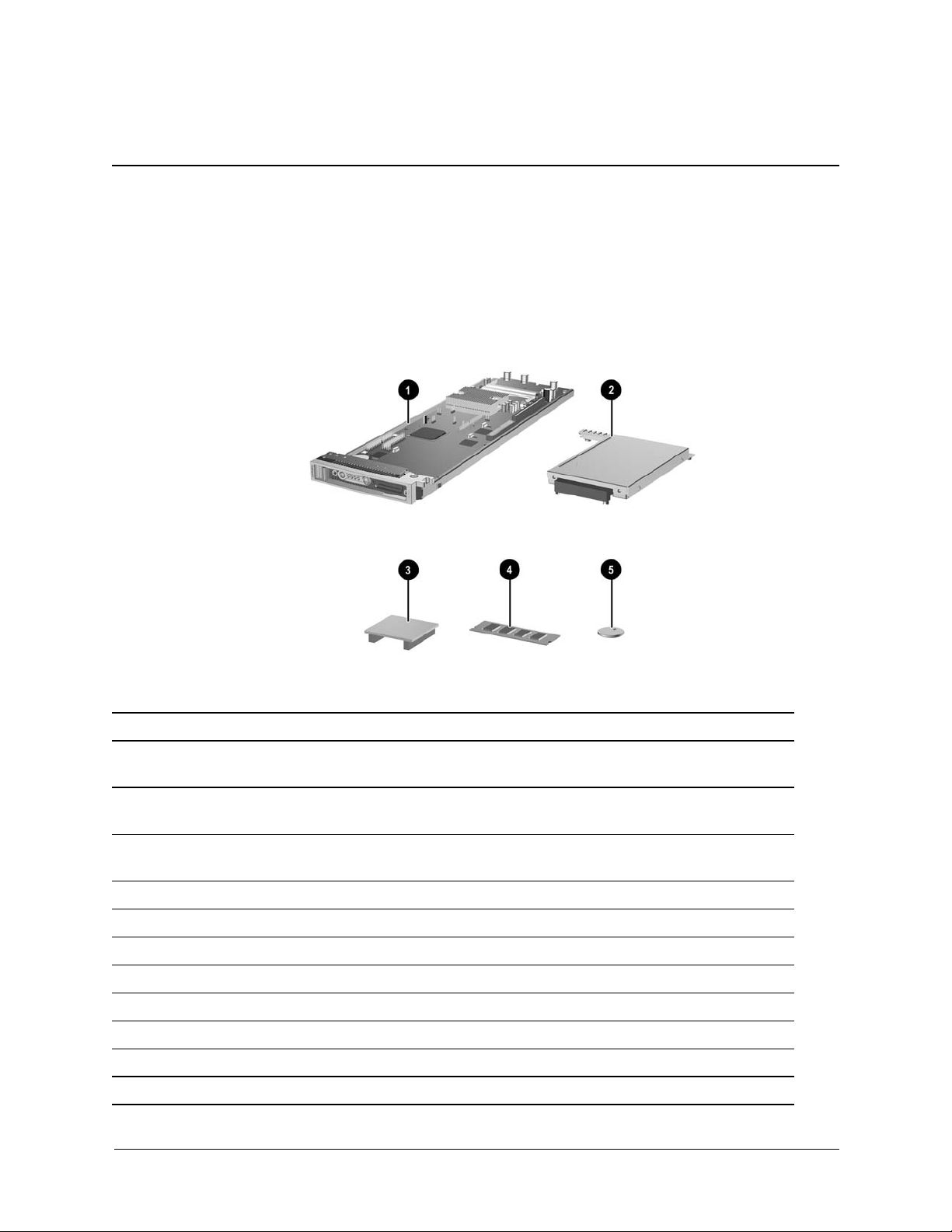
Spare Parts
bc1000 Spare
Item Description
1 Blade PC complete with 1 memory module 4,
hard drive 2, and RTC battery 5
1 Blade PC complete with 1 memory module 1,
hard drive 2, and RTC battery 3 (Japan only)
1* Blade PC with RTC battery 5 but no other parts. N/A* N/A*
2* 40 GB Hard drive complete with mtg. bracket N/A* N/A*
3 Graphics diagnostic card (for debug use only) 404275-001 404275-001
4 Memory module, 256 MB SODIMM 407679-001 407679-001
Memory module, 512 MB SODIMM 407680-001 407680-001
Memory module, 1 GB SODIMM 407724-001 407724-001
5* RTC battery N/A* N/A*
*Parts available after expiration of advance exchange warranty.
Service Reference Guide bc1000 and bc1500 352971-005 1–1
Part Number
404273-001 404273-001
N/A 407510-291
bc1500 Spare
Part Number
Page 8

Spare Parts
1–2 352971-005 Service Reference Guide bc1000 and bc1500
Page 9
Removal and Replacement
The Blade PC may be covered under an advance exchange warranty provision. Check the
✎
warranty documentation that came with your Blade PC for more information.
2.1 Returning the Blade PC
Before returning the Blade PC for repairs:
1. Reinstall the image on the hard drive before calling for a replacement unit. A faulty image
can act like a component failure.
2. Remove any extra memory and the graphics diagnostic card you may have installed on the
Blade PC. Only the original amount of memory will be shipped on the replacement unit
2.2 Removal and Replacement
2
2.2.1 Powering Down the BladeSystem PC
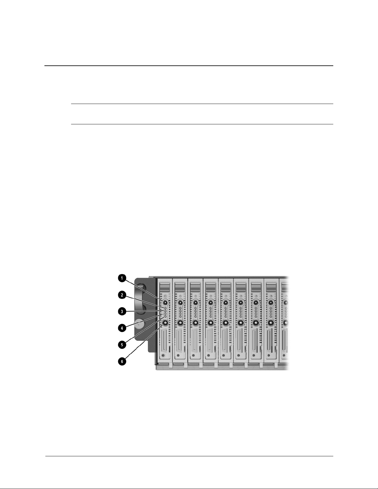
1. Ensure the blade PC is not active by verifying that the Health LED (Item 2) is off.
Service Reference Guide bc1000 and bc1500 352971-004 2–1
Page 10

Removal and Replacement
Item LED Status Description
1 Unit
Identification
2 Health Off =
3 NIC A Off =
4 NIC B Off =
5 Drive activity Off =
6 Power Off =
Off =
Blue =
Blue blinking =
Green =
Amber =
Red =
Red blinking =
Green=
Green blinking =
Green=
Green blinking =
Green blinking =
Amber=
Green =
Off
Identification of blade PC
Being emotely accessed
Blade PC off
Blade PC on and good health
Blade PC degraded or power-up prohibited ny
the Integrated Administrator.
Blade PC critical
Blade PC critical
No connection
Linked to network
Linked and activity on the network
No connection
Linked to network
Linked and activity on the network
No drive activity
Drive activity
No AC power to enclosure or blade PC
Envclosutre on and health good
Blade PC power turned on
2. If the blade is active, notify the users and stop applications as necessary.
3. Shut down the operating system. This may shut off the blade PC power.
4. If the blade PC still has power, power down the blade PC by either:
❏ Using the Integrated Administrator or
❏ Pressing the power button 6 on the front of the blade PC above.
To perform an emergency shut down of the blade PC, press and hold the blade power button for
four seconds.
CAUTION: Performing an emergency shutdown on a blade PC may result in the loss of any unsaved
Ä
data.
2–2 352971-004 Service Reference Guide bc1000 and bc1500
Page 11

2.2.2 Removing the BladeSystem PC
To remove a blade PC:
1. Power down the blade PC. See “Removal and Replacement” on page 1
2. Press the release latch 1.
3. Pull down the ejector lever 2.
4. Remove the blade PC from the enclosure.
Removal and Replacement
To install a new blade PC, reverse the removal procedures.
Service Reference Guide bc1000 and bc1500 352971-004 2–3
Page 12

Removal and Replacement
2.2.3 Replacing the Memory
1. Power down the blade PC. See “Removal and Replacement” on page 1
2. Remove the blade.
3. Release the latches on each side of the DIMM slot 1. This will allow the module to rotate
upwards.
4. Remove the DIMM from the slot 2.
2–4 352971-004 Service Reference Guide bc1000 and bc1500
Page 13

Removal and Replacement
To replace the module:
1. Insert the DIMM at a 15 degree angle 1, making sure that the notch on the bottom of the
DIMM aligns with the notch in the socket.
2. Press the DIMM down towards the board 2, ensuring that it is fully seated and the two
latches snap into place.
Service Reference Guide bc1000 and bc1500 352971-004 2–5
Page 14

Removal and Replacement
2.2.4 Installing the Optional Graphics Diagnostic Card
1. Power down the Blade PC.
2. Remove the blade.
3. Lay the Blade PC down on a flat surface and install the graphics card into the sockets.
The card’s pins are keyed so that it will only install one way.
✎
To remove the card, pull it firmly, straight out of the sockets.
2–6 352971-004 Service Reference Guide bc1000 and bc1500
Page 15

2.2.5 Installing the Diagnostic Adapter
1. Power down the Blade PC.
2. Insert the adapter into the diagnostic connector on the front of the blade 1.
3. Tighten the thumbscrews that secure the adapter in place 2.
Removal and Replacement
Attaching the USB 1.1 diagnostic adapter
Attaching the USB 2.0 diagnostic adapter
To remove the diagnostic adapter, reverse the removal procedures.
Service Reference Guide bc1000 and bc1500 352971-004 2–7
Page 16

Removal and Replacement
2–8 352971-004 Service Reference Guide bc1000 and bc1500
Page 17
Connectors and Passwords
3.1 Connectors and Jumpers
3
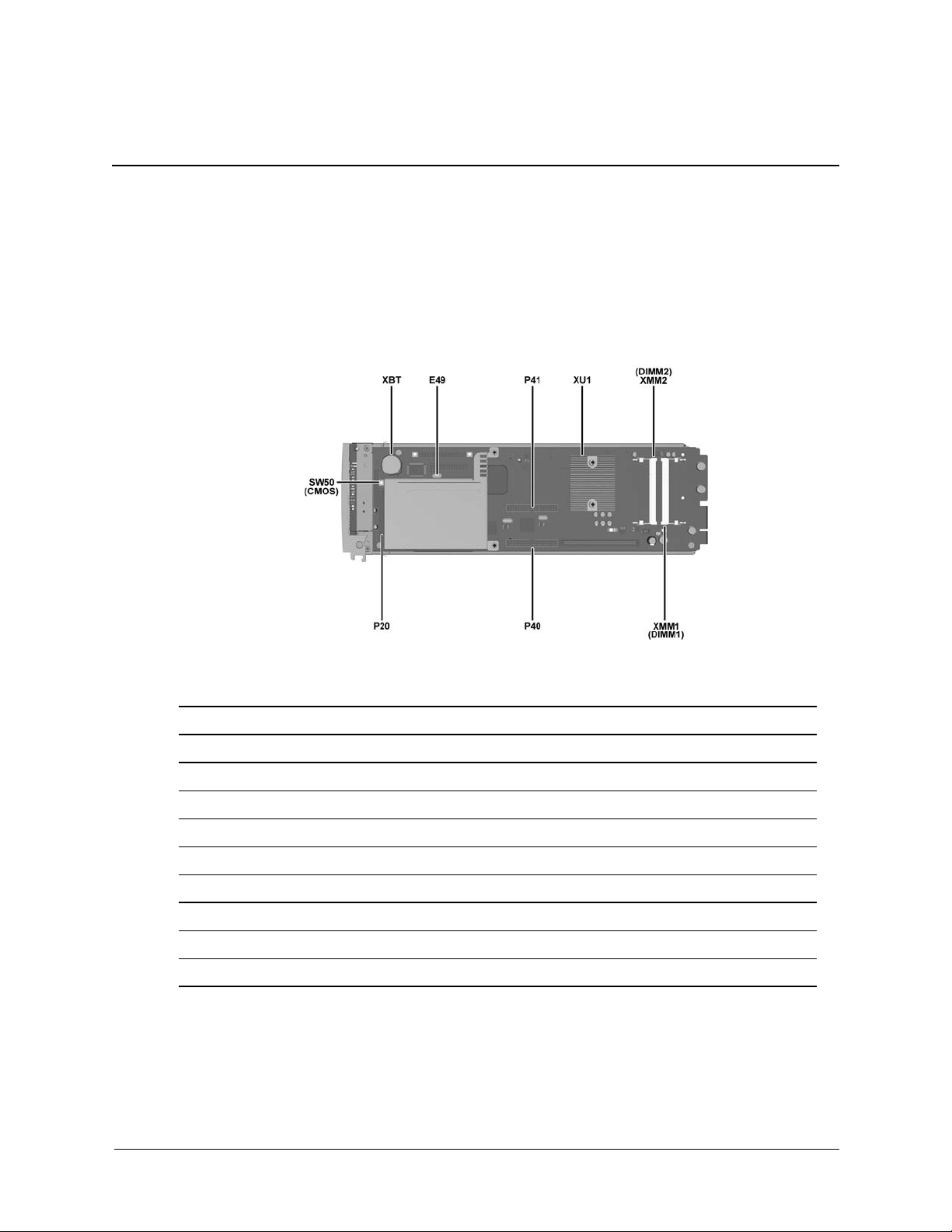
Connectors and Jumpers
Item Description
E49 Password jumper
P40 Graphics diagnostic card connector (outboard)
P41 Graphics diagnostic card connector (inboard)
SW50 or CMOS CMOS reset button
XBT RTC battery
XMM1 or DIMM1 Memory module socket 1
XMM2 or DIMM2 Memory module socket 2
XU1 Processor socket
Service Reference Guide bc1000 and bc1500 352971-005 3–1
Page 18

Connectors and Passwords
3.2 Passwords
3.2.1 Remove a Setup Password
1. Power down the Blade PC.
2. Remove the blade.
3. Install a jumper on the E49 header.
4. Power up the unit. The password is now removed.
3.2.2 Establish a Setup Password
Power down the Blade PC.
1. Remove the blade.
2. Remove the jumper from the E49 header.
3. Power up and Use F10 retup to establish the setup pasword.
3–2 352971-005 Service Reference Guide bc1000 and bc1500
Page 19

4.1 Diagnostic Indicator Lights
Diagnostic Indicator Lights
Health
LED Activity Problem Corrective Action
4
Diagnostics
Red Solid VRM (Blade system
board) failure
Red 2 Blinks Unit overheating • Check processor heatsink.
Red 3 Blinks CPU (Blade system
board) failure
Red 4 Blinks Blade power failure Move blade to different bay. If:
Red 5 Blinks Bad memory or
memory-related error
Red 6 Blinks Bad graphics
diagnostic card
Red 7 Blinks Blade system board
failure
Replace blade.
• Verify system fans working properly.
• Replace blade.
Replace blade.
• problem follows the move, replace the
blade.
• problem is solved - enclosure backplane
problem.
• Reseat memory and reboot.
• Replace memory.
• Replace blade.
• Replace graphics diagnostic card.
• Replace blade.
Replace blade.
Amber* Solid Bad ROM Upgrade • Flash ROM.
• Download or use a different ROM image.
*Main power turned on
#Main power turned off
Service Reference Guide bc1000 and bc1500 352971-005 4–1
Page 20

Diagnostics
Diagnostic Indicator Lights
Health
LED Activity Problem Corrective Action
Amber# Solid Temperature Caution
graceful shutdown
NONE NONE Enclosure or blade
system board power
failure
*Main power turned on
#Main power turned off
Blade has shut down gracefully becasue of an
overtemperature situation. When main power is
reestablished, the condition will self-correct but
post-video POST message will be displayed.
If enclosure Health is OK, move blade to
different bay. If:
• problem follows the move, replace the
blade.
• problem is solved - enclosure backplane
problem.
4–2 352971-005 Service Reference Guide bc1000 and bc1500
Page 21

4.2 POST (Power On Self Test) Error Messages
POST Error Messages
Health
Message
LED Corrective Action
Diagnostics
101-O pt i on ROM C he cks um
Error
102/103-System Board error Red • Clear CMOS.
162-System Options Not Set Amber • Set time and date in Computer Setup.
163-Time & Date Not Set Amber • Set time and date in Computer Setup.
164-Memory Size Error Amber • Ensure DIMMs are properly installed.
201-Memory Error Red • Ensure DIMMs are properly installed.
Red • Clear CMOS
• Flash ROM if necessary.
• Replace the blade.
• Replace the blade.
• Replace the RTC battery.
• Replace the RTC battery.
• Verify proper DIMM type.
• Remove and replace modules one at a time to
isolate faulty module.
• Replace blade.
• Verify proper DIMM type.
• Remove and replace modules one at a time to
isolate faulty module.
• Replace blade.
.
303-Keyboard Controller Error Amber • Reconnect keyboard with blade turned off.
•Try different keyboard.
• Replace blade
304-Keyboard or System Unit
Error
172 0 - S M A RT H a r d D ri v e
detects immanent failure
1780-Disk 0 Failure Amber • Run Computer Setup IDE self test from Computer
Service Reference Guide bc1000 and bc1500 352971-005 4–3
Amber • Reconnect keyboard with blade turned off.
•Replace keyboard.
• Replace blade.
Amber • Run Drive Protection System test if applicable.
• Apply firmware patch (www.hp.com/support).
• Back up contents and replace the hard drive.
Setup.
•Replace hard drive.
Page 22

Diagnostics
POST Error Messages
Health
Message
1782-Disk Controller Failure Red • Run Computer Setup IDE self test from Computer
1790-Disk 0 Error Amber • Run Computer Setup IDE self test from Computer
1800-Temperature Alert Amber • Check that enclosure fans are running.
LED Corrective Action
Setup.
•Replace hard drive.
• Replace blade.
Setup.
•Replace hard drive.
• Replace blade.
• Check that there is air flow between the fans and
the blade.
• Check the processor heat sink
• Replace the blade
1998 - M as t er B o ot R ec o rd
Backup has been lost.
Invalid Electronic Serial
Number
Amber Run Computer Setup to update the MBR Backup.
Amber • Run Computer Setup. If data is loaded/will not
allow changes download SP5572.EXE
(SNZERO.EXE) from www.hp.com.
• Run Computer Setup, enter serial number under
Security, System ID, then save changes.
4–4 352971-005 Service Reference Guide bc1000 and bc1500
 Loading...