

Page 1

Embedded Web System
User Guide
for the HP BladeSystem PC Blade Switch
Document Part Number: 413353-002
June 2006
Page 2

© Copyright 2006 Hewlett-Packard Development Company, L.P.
The information contained herein is subject to change without notice.
The only warranties for HP products and services are set forth in the express warranty statements accompanying
such products and services. Nothing herein should be construed as constituting an additional warranty. HP shall
not be liable for technical or editorial errors or omissions contained herein.
This document contains proprietary information that is protected by copyright. No part of this document may be
photocopied, reproduced, or translated to another language without the prior written consent of Hewlett-Packard
Company.
WARNING: Text set off in this manner indicates that failure to follow directions could result in bodily
Å
harm or loss of life.
CAUTION: Text set off in this manner indicates that failure to follow directions could result in damage
Ä
to equipment or loss of information.
Embedded Web System User Guide
for the HP BladeSystem PC Blade Switch
First Edition (February 2006)
Second Edition (June 2006)
Document Part Number: 413353-002
Page 3

Contents
Preface
1 Getting Started
Starting the Application . . . . . . . . . . . . . . . . . . . . . . . . . . . . . . . . . . . . . . . . . . . . . . . . . . . . . . . . . . . 1–1
Understanding the Interface . . . . . . . . . . . . . . . . . . . . . . . . . . . . . . . . . . . . . . . . . . . . . . . . . . . . . . . . 1–2
Using the Management Buttons . . . . . . . . . . . . . . . . . . . . . . . . . . . . . . . . . . . . . . . . . . . . . . . . . 1–3
Device Representation. . . . . . . . . . . . . . . . . . . . . . . . . . . . . . . . . . . . . . . . . . . . . . . . . . . . . . . . . 1–4
Using Screen and Table Options . . . . . . . . . . . . . . . . . . . . . . . . . . . . . . . . . . . . . . . . . . . . . . . . . 1–4
Adding Device Information . . . . . . . . . . . . . . . . . . . . . . . . . . . . . . . . . . . . . . . . . . . . . . . . . 1–5
Modifying Device Information . . . . . . . . . . . . . . . . . . . . . . . . . . . . . . . . . . . . . . . . . . . . . . . 1–5
Deleting Device Information . . . . . . . . . . . . . . . . . . . . . . . . . . . . . . . . . . . . . . . . . . . . . . . . 1–5
Resetting the Device . . . . . . . . . . . . . . . . . . . . . . . . . . . . . . . . . . . . . . . . . . . . . . . . . . . . . . . . . . . . . 1–6
Logging Off the Device . . . . . . . . . . . . . . . . . . . . . . . . . . . . . . . . . . . . . . . . . . . . . . . . . . . . . . . . . . . 1–6
2 Defining System Information
3 Configuring System Time
Configuring Daylight Savings Time . . . . . . . . . . . . . . . . . . . . . . . . . . . . . . . . . . . . . . . . . . . . . . . . . 3–1
Configuring SNTP . . . . . . . . . . . . . . . . . . . . . . . . . . . . . . . . . . . . . . . . . . . . . . . . . . . . . . . . . . . . . . . 3–5
Defining SNTP Global Settings . . . . . . . . . . . . . . . . . . . . . . . . . . . . . . . . . . . . . . . . . . . . . . . . . 3–6
Defining SNTP Servers. . . . . . . . . . . . . . . . . . . . . . . . . . . . . . . . . . . . . . . . . . . . . . . . . . . . . 3–7
Defining SNTP Authentication . . . . . . . . . . . . . . . . . . . . . . . . . . . . . . . . . . . . . . . . . . . . . . . . . . 3–8
4 Configuring Device Security
Configuring Authentication Methods . . . . . . . . . . . . . . . . . . . . . . . . . . . . . . . . . . . . . . . . . . . . . . . . 4–1
Defining Access Profiles . . . . . . . . . . . . . . . . . . . . . . . . . . . . . . . . . . . . . . . . . . . . . . . . . . . . . . . 4–1
Defining Profile Rules . . . . . . . . . . . . . . . . . . . . . . . . . . . . . . . . . . . . . . . . . . . . . . . . . . . . . . . . . 4–4
Defining Authentication Profiles. . . . . . . . . . . . . . . . . . . . . . . . . . . . . . . . . . . . . . . . . . . . . . . . . 4–6
Mapping Authentication Methods . . . . . . . . . . . . . . . . . . . . . . . . . . . . . . . . . . . . . . . . . . . . . . . . 4–9
Defining TACACS+ Authentication . . . . . . . . . . . . . . . . . . . . . . . . . . . . . . . . . . . . . . . . . . . . . 4–11
Defining RADIUS Settings . . . . . . . . . . . . . . . . . . . . . . . . . . . . . . . . . . . . . . . . . . . . . . . . . . . . 4–14
Configuring Passwords . . . . . . . . . . . . . . . . . . . . . . . . . . . . . . . . . . . . . . . . . . . . . . . . . . . . . . . 4–17
Defining Local Users . . . . . . . . . . . . . . . . . . . . . . . . . . . . . . . . . . . . . . . . . . . . . . . . . . . . . 4–17
Defining Line Passwords . . . . . . . . . . . . . . . . . . . . . . . . . . . . . . . . . . . . . . . . . . . . . . . . . . 4–19
Defining Enable Passwords . . . . . . . . . . . . . . . . . . . . . . . . . . . . . . . . . . . . . . . . . . . . . . . . 4–21
Configuring Network Security. . . . . . . . . . . . . . . . . . . . . . . . . . . . . . . . . . . . . . . . . . . . . . . . . . . . . 4–22
Network Security Overview . . . . . . . . . . . . . . . . . . . . . . . . . . . . . . . . . . . . . . . . . . . . . . . . . . . 4–22
Port-Based Authentication . . . . . . . . . . . . . . . . . . . . . . . . . . . . . . . . . . . . . . . . . . . . . . . . . 4–22
Advanced Port-Based Authentication. . . . . . . . . . . . . . . . . . . . . . . . . . . . . . . . . . . . . . . . . 4–22
Embedded Web System User Guide www.hp.com iii
Page 4

Contents
Defining Port Authentication Properties . . . . . . . . . . . . . . . . . . . . . . . . . . . . . . . . . . . . . . . . . . 4–23
Defining Port Authentication. . . . . . . . . . . . . . . . . . . . . . . . . . . . . . . . . . . . . . . . . . . . . . . . . . . 4–24
Configuring Multiple Hosts . . . . . . . . . . . . . . . . . . . . . . . . . . . . . . . . . . . . . . . . . . . . . . . . 4–27
Defining Authentication Hosts . . . . . . . . . . . . . . . . . . . . . . . . . . . . . . . . . . . . . . . . . . . . . . 4–29
Viewing EAP Statistics. . . . . . . . . . . . . . . . . . . . . . . . . . . . . . . . . . . . . . . . . . . . . . . . . . . . 4–30
Configuring Traffic Control . . . . . . . . . . . . . . . . . . . . . . . . . . . . . . . . . . . . . . . . . . . . . . . . . . . 4–31
Defining Access Control Lists . . . . . . . . . . . . . . . . . . . . . . . . . . . . . . . . . . . . . . . . . . . . . . 4–31
Defining MAC Based Access Control Lists . . . . . . . . . . . . . . . . . . . . . . . . . . . . . . . . . . . . 4–37
Managing Port Security . . . . . . . . . . . . . . . . . . . . . . . . . . . . . . . . . . . . . . . . . . . . . . . . . . . 4–42
Enabling Storm Control . . . . . . . . . . . . . . . . . . . . . . . . . . . . . . . . . . . . . . . . . . . . . . . . . . . 4–44
5 Configuring System Logs
Defining General Log Properties . . . . . . . . . . . . . . . . . . . . . . . . . . . . . . . . . . . . . . . . . . . . . . . . . . . . 5–2
Viewing Memory Logs . . . . . . . . . . . . . . . . . . . . . . . . . . . . . . . . . . . . . . . . . . . . . . . . . . . . . . . . . . . 5–3
Viewing Flash Logs . . . . . . . . . . . . . . . . . . . . . . . . . . . . . . . . . . . . . . . . . . . . . . . . . . . . . . . . . . . . . . 5–4
Defining System Log Servers . . . . . . . . . . . . . . . . . . . . . . . . . . . . . . . . . . . . . . . . . . . . . . . . . . . . . . 5–5
6 Configuring Interfaces
Configuring Ports . . . . . . . . . . . . . . . . . . . . . . . . . . . . . . . . . . . . . . . . . . . . . . . . . . . . . . . . . . . . . . . . 6–1
Aggregating Ports. . . . . . . . . . . . . . . . . . . . . . . . . . . . . . . . . . . . . . . . . . . . . . . . . . . . . . . . . . . . . . . . 6–4
Configuring LAG Parameters . . . . . . . . . . . . . . . . . . . . . . . . . . . . . . . . . . . . . . . . . . . . . . . . . . . 6–5
Configuring LAG Membership . . . . . . . . . . . . . . . . . . . . . . . . . . . . . . . . . . . . . . . . . . . . . . . . . . 6–7
Configuring LACP Parameters . . . . . . . . . . . . . . . . . . . . . . . . . . . . . . . . . . . . . . . . . . . . . . . . . . 6–9
Configuring VLANs. . . . . . . . . . . . . . . . . . . . . . . . . . . . . . . . . . . . . . . . . . . . . . . . . . . . . . . . . . . . . 6–10
Defining VLAN Properties . . . . . . . . . . . . . . . . . . . . . . . . . . . . . . . . . . . . . . . . . . . . . . . . . . . . 6–11
Defining VLAN Membership . . . . . . . . . . . . . . . . . . . . . . . . . . . . . . . . . . . . . . . . . . . . . . . . . . 6–13
Defining VLAN Interface Settings . . . . . . . . . . . . . . . . . . . . . . . . . . . . . . . . . . . . . . . . . . . . . . 6–14
Configuring GARP . . . . . . . . . . . . . . . . . . . . . . . . . . . . . . . . . . . . . . . . . . . . . . . . . . . . . . . . . . 6–16
Defining GARP. . . . . . . . . . . . . . . . . . . . . . . . . . . . . . . . . . . . . . . . . . . . . . . . . . . . . . . . . . 6–16
Defining GVRP. . . . . . . . . . . . . . . . . . . . . . . . . . . . . . . . . . . . . . . . . . . . . . . . . . . . . . . . . . 6–18
Viewing GVRP Statistics . . . . . . . . . . . . . . . . . . . . . . . . . . . . . . . . . . . . . . . . . . . . . . . . . . 6–20
7 Defining IP Addresses
Configuring IP Addressing . . . . . . . . . . . . . . . . . . . . . . . . . . . . . . . . . . . . . . . . . . . . . . . . . . . . . . . . 7–1
Defining IP Addresses . . . . . . . . . . . . . . . . . . . . . . . . . . . . . . . . . . . . . . . . . . . . . . . . . . . . . . . . . 7–1
Defining ARP . . . . . . . . . . . . . . . . . . . . . . . . . . . . . . . . . . . . . . . . . . . . . . . . . . . . . . . . . . . . . . . 7–3
Defining Domain Name Servers . . . . . . . . . . . . . . . . . . . . . . . . . . . . . . . . . . . . . . . . . . . . . . . . . . . . 7–5
Defining DNS Servers . . . . . . . . . . . . . . . . . . . . . . . . . . . . . . . . . . . . . . . . . . . . . . . . . . . . . . . . . 7–5
Defining DNS Host Mapping . . . . . . . . . . . . . . . . . . . . . . . . . . . . . . . . . . . . . . . . . . . . . . . . . . . 7–7
8 Defining the Forwarding Database
Defining Static Forwarding Database Entries . . . . . . . . . . . . . . . . . . . . . . . . . . . . . . . . . . . . . . . . . . 8–1
Defining Dynamic Forwarding Database Entries . . . . . . . . . . . . . . . . . . . . . . . . . . . . . . . . . . . . . . . 8–3
9 Configuring Spanning Tree
Defining Classic Spanning Tree. . . . . . . . . . . . . . . . . . . . . . . . . . . . . . . . . . . . . . . . . . . . . . . . . . . . . 9–2
iv www.hp.com Embedded Web System User Guide
Page 5

Defining STP on Interfaces . . . . . . . . . . . . . . . . . . . . . . . . . . . . . . . . . . . . . . . . . . . . . . . . . . . . . . . . 9–4
Defining Rapid Spanning Tree. . . . . . . . . . . . . . . . . . . . . . . . . . . . . . . . . . . . . . . . . . . . . . . . . . . . . . 9–7
Defining Multiple Spanning Tree . . . . . . . . . . . . . . . . . . . . . . . . . . . . . . . . . . . . . . . . . . . . . . . . . . . 9–9
Defining MSTP Instance Settings . . . . . . . . . . . . . . . . . . . . . . . . . . . . . . . . . . . . . . . . . . . . . . . 9–10
Defining MSTP Interface Settings . . . . . . . . . . . . . . . . . . . . . . . . . . . . . . . . . . . . . . . . . . . . . . 9–12
Instance to VLAN . . . . . . . . . . . . . . . . . . . . . . . . . . . . . . . . . . . . . . . . . . . . . . . . . . . . . . . . 9–15
10Configuring Multicast Forwarding
Defining IGMP Snooping . . . . . . . . . . . . . . . . . . . . . . . . . . . . . . . . . . . . . . . . . . . . . . . . . . . . . . . . 10–1
Defining Multicast Bridging Groups . . . . . . . . . . . . . . . . . . . . . . . . . . . . . . . . . . . . . . . . . . . . . . . . 10–3
Defining Multicast Forward All Settings. . . . . . . . . . . . . . . . . . . . . . . . . . . . . . . . . . . . . . . . . . . . . 10–5
11Configuring SNMP
SNMP v1 and v2c . . . . . . . . . . . . . . . . . . . . . . . . . . . . . . . . . . . . . . . . . . . . . . . . . . . . . . . . . . . . . . 11–1
SNMP v3 . . . . . . . . . . . . . . . . . . . . . . . . . . . . . . . . . . . . . . . . . . . . . . . . . . . . . . . . . . . . . . . . . . . . . 11–1
Configuring SNMP Security . . . . . . . . . . . . . . . . . . . . . . . . . . . . . . . . . . . . . . . . . . . . . . . . . . . . . . 11–2
Defining SNMP Security. . . . . . . . . . . . . . . . . . . . . . . . . . . . . . . . . . . . . . . . . . . . . . . . . . . . . . 11–2
Defining SNMP Views . . . . . . . . . . . . . . . . . . . . . . . . . . . . . . . . . . . . . . . . . . . . . . . . . . . . . . . 11–3
Defining SNMP Group Profiles . . . . . . . . . . . . . . . . . . . . . . . . . . . . . . . . . . . . . . . . . . . . . . . . 11–4
Defining SNMP Group Membership. . . . . . . . . . . . . . . . . . . . . . . . . . . . . . . . . . . . . . . . . . . . . 11–6
Defining SNMP Communities. . . . . . . . . . . . . . . . . . . . . . . . . . . . . . . . . . . . . . . . . . . . . . . . . . 11–9
Configuring SNMP Notifications . . . . . . . . . . . . . . . . . . . . . . . . . . . . . . . . . . . . . . . . . . . . . . . . . 11–11
Defining SNMP Notification Global Parameters . . . . . . . . . . . . . . . . . . . . . . . . . . . . . . . . . . 11–11
Defining SNMP Notification Filters . . . . . . . . . . . . . . . . . . . . . . . . . . . . . . . . . . . . . . . . . . . . 11–12
Defining SNMP Notification Recipients. . . . . . . . . . . . . . . . . . . . . . . . . . . . . . . . . . . . . . . . . 11–13
Contents
12Managing System Files
Downloading System Files . . . . . . . . . . . . . . . . . . . . . . . . . . . . . . . . . . . . . . . . . . . . . . . . . . . . . . . 12–2
Uploading System Files . . . . . . . . . . . . . . . . . . . . . . . . . . . . . . . . . . . . . . . . . . . . . . . . . . . . . . . . . . 12–3
Copying Files . . . . . . . . . . . . . . . . . . . . . . . . . . . . . . . . . . . . . . . . . . . . . . . . . . . . . . . . . . . . . . . . . . 12–4
Activating the Image File. . . . . . . . . . . . . . . . . . . . . . . . . . . . . . . . . . . . . . . . . . . . . . . . . . . . . . . . . 12–5
13Configuring Quality of Service
Quality of Service Overview . . . . . . . . . . . . . . . . . . . . . . . . . . . . . . . . . . . . . . . . . . . . . . . . . . . . . . 13–1
VPT Classification Information. . . . . . . . . . . . . . . . . . . . . . . . . . . . . . . . . . . . . . . . . . . . . . . . . 13–1
CoS Services . . . . . . . . . . . . . . . . . . . . . . . . . . . . . . . . . . . . . . . . . . . . . . . . . . . . . . . . . . . . . . . 13–1
Defining General QoS Settings . . . . . . . . . . . . . . . . . . . . . . . . . . . . . . . . . . . . . . . . . . . . . . . . . . . . 13–2
Configuring QoS General Settings . . . . . . . . . . . . . . . . . . . . . . . . . . . . . . . . . . . . . . . . . . . . . . 13–2
Restoring Factory Default QoS Interface Settings . . . . . . . . . . . . . . . . . . . . . . . . . . . . . . . . . . 13–3
Defining Queues . . . . . . . . . . . . . . . . . . . . . . . . . . . . . . . . . . . . . . . . . . . . . . . . . . . . . . . . . . . . 13–3
Defining Rate Limiting . . . . . . . . . . . . . . . . . . . . . . . . . . . . . . . . . . . . . . . . . . . . . . . . . . . . . . . 13–4
Mapping CoS Values to Queues . . . . . . . . . . . . . . . . . . . . . . . . . . . . . . . . . . . . . . . . . . . . . . . . 13–7
Mapping DSCP Values to Queues. . . . . . . . . . . . . . . . . . . . . . . . . . . . . . . . . . . . . . . . . . . . . . . 13–8
Defining QoS Basic Mode . . . . . . . . . . . . . . . . . . . . . . . . . . . . . . . . . . . . . . . . . . . . . . . . . . . . . . . . 13–9
Defining Basic Mode Settings. . . . . . . . . . . . . . . . . . . . . . . . . . . . . . . . . . . . . . . . . . . . . . . . . . 13–9
Rewriting Basic Mode DSCP Values . . . . . . . . . . . . . . . . . . . . . . . . . . . . . . . . . . . . . . . . . . . 13–10
Defining QoS Advanced Mode . . . . . . . . . . . . . . . . . . . . . . . . . . . . . . . . . . . . . . . . . . . . . . . . . . . 13–11
Embedded Web System User Guide www.hp.com v
Page 6

Contents
Configuring DSCP Mapping . . . . . . . . . . . . . . . . . . . . . . . . . . . . . . . . . . . . . . . . . . . . . . . . . . 13–11
Class Mapping . . . . . . . . . . . . . . . . . . . . . . . . . . . . . . . . . . . . . . . . . . . . . . . . . . . . . . . . . . . . . 13–12
Defining Aggregate Policer . . . . . . . . . . . . . . . . . . . . . . . . . . . . . . . . . . . . . . . . . . . . . . . . . . . 13–14
Defining Policies . . . . . . . . . . . . . . . . . . . . . . . . . . . . . . . . . . . . . . . . . . . . . . . . . . . . . . . . . . . 13–16
Setting Policy Binding. . . . . . . . . . . . . . . . . . . . . . . . . . . . . . . . . . . . . . . . . . . . . . . . . . . . . . . 13–19
14Managing Device Diagnostics
Configuring Port Mirroring . . . . . . . . . . . . . . . . . . . . . . . . . . . . . . . . . . . . . . . . . . . . . . . . . . . . . . . 14–1
Viewing Integrated Cable Tests . . . . . . . . . . . . . . . . . . . . . . . . . . . . . . . . . . . . . . . . . . . . . . . . . . . . 14–3
Viewing Optical Transceivers . . . . . . . . . . . . . . . . . . . . . . . . . . . . . . . . . . . . . . . . . . . . . . . . . . . . . 14–4
Viewing CPU Utilization . . . . . . . . . . . . . . . . . . . . . . . . . . . . . . . . . . . . . . . . . . . . . . . . . . . . . . . . . 14–5
15Viewing Statistics
Viewing Interface Statistics . . . . . . . . . . . . . . . . . . . . . . . . . . . . . . . . . . . . . . . . . . . . . . . . . . . . . . . 15–1
Viewing Interface Statistics. . . . . . . . . . . . . . . . . . . . . . . . . . . . . . . . . . . . . . . . . . . . . . . . . . . . 15–1
Viewing Etherlike Statistics . . . . . . . . . . . . . . . . . . . . . . . . . . . . . . . . . . . . . . . . . . . . . . . . . . . 15–3
Managing RMON Statistics . . . . . . . . . . . . . . . . . . . . . . . . . . . . . . . . . . . . . . . . . . . . . . . . . . . . . . . 15–4
Viewing RMON Statistics . . . . . . . . . . . . . . . . . . . . . . . . . . . . . . . . . . . . . . . . . . . . . . . . . . . . . 15–4
Configuring RMON History . . . . . . . . . . . . . . . . . . . . . . . . . . . . . . . . . . . . . . . . . . . . . . . . . . . 15–6
Defining RMON History Control . . . . . . . . . . . . . . . . . . . . . . . . . . . . . . . . . . . . . . . . . . . . 15–6
Viewing the RMON History Table. . . . . . . . . . . . . . . . . . . . . . . . . . . . . . . . . . . . . . . . . . . 15–8
Configuring RMON Events. . . . . . . . . . . . . . . . . . . . . . . . . . . . . . . . . . . . . . . . . . . . . . . . . . . . 15–9
Defining RMON Events Control . . . . . . . . . . . . . . . . . . . . . . . . . . . . . . . . . . . . . . . . . . . . 15–9
Viewing the RMON Events Logs . . . . . . . . . . . . . . . . . . . . . . . . . . . . . . . . . . . . . . . . . . . 15–11
Defining RMON Alarms. . . . . . . . . . . . . . . . . . . . . . . . . . . . . . . . . . . . . . . . . . . . . . . . . . 15–12
Glossary
Index
vi www.hp.com Embedded Web System User Guide
Page 7

The Embedded Web System (EWS) is an intricate network management system. The EWS
configures, monitors, and troubleshoots network devices from a remote Web browser. The EWS
web pages are easy-to-use and easy-to-navigate. In addition, the EWS provides real time graphs
and RMON statistics to help system administrators monitor network performance.
This preface provides an overview to the Embedded Web Server User Guide, and includes the
following sections:
■ Embedded Web System User Guide Overview
■ Intended Audience
Embedded Web System User Guide Overview
This section provides an overview to the Embedded Web System User Guide. The Embedded
Web System User Guide provides the following sections:
■ Chapter 1, “Getting Started” — Provides information for using the Embedded Web
Management System, including adding, editing, and deleting device configuration
information.
■ Chapter 2, “Defining System Information” — Provides information for defining basic
device information, including the user-defined system name, the user-defined system
location, and the system contact person.
Preface
■ Chapter 3, “Configuring System Time” — Provides information for defining basic device
information, including the user-defined system name, the user-defined system location, and
the system contact person.
■ Chapter 4, “Configuring Device Security” — Provides information for configuring both
system and network security, including traffic control, ACLs, and device access methods.
■ Chapter 5, “Configuring System Logs” — Provides information for viewing system logs
and configuring device log servers.
■ Chapter 6, “Configuring Interfaces” — Provides information for defining ports, LAGs,
and VLANs.
■ Chapter 7, “Defining IP Addresses” — Provides information for configuring IP addresses,
DHCP, ARP, and Domain Name Servers.
■ Chapter 8, “Defining the Forwarding Database” — Provides information for configuring
both the static and dynamic forwarding databases.
■ Chapter 9, “Configuring Spanning Tree” — Provides information for configuring Classic,
Rapid, and multiple Spanning Tree.
■ Chapter 10, “Configuring Multicast Forwarding” — Provides information for
configuring Multicast forwarding.
Embedded Web System User Guide www.hp.com vii
Page 8

Preface
■ Chapter 11, “Configuring SNMP” — Provides information for configuring SNMP access
and management.
■ Chapter 13, “Configuring Quality of Service” — Provides information for Basic and
Advanced Quality of Service, including DSCP and CoS mapping, policies, and configuring
Trust mode.
■ Chapter 12, “Managing System Files” — Provides information for managing system files.
■ Chapter 14, “Managing Device Diagnostics” — Provides information for configuring port
mirroring, performing cable tests, and viewing device health information.
■ Chapter 15, “Viewing Statistics” — Provides information for viewing RMON and
interface statistics.
Intended Audience
This guide is intended for network administrators familiar with IT concepts and terminology.
viii www.hp.com Embedded Web System User Guide
Page 9
This section provides an introduction to the user interface, and includes the following topics:
■ Starting the Application
■ Understanding the Interface
■ Resetting the Device
■ Logging Off the Device
Starting the Application
This section contains information for starting the application.
To open the EWS application:
1. Open a Web browser.
1
Getting Started
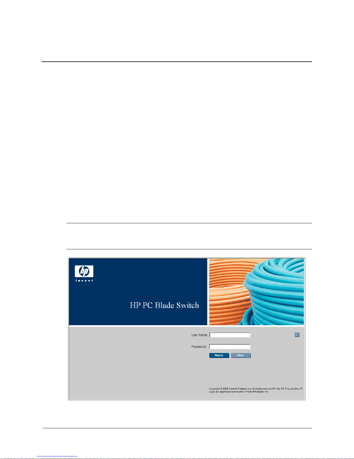
2. Enter the device’s IP address in the address bar and press
authentication home page will load.
By default, the switch uses DHCP to get an IP address for an interface on each of the two default
✎
VLANs. The VLAN you choose to manage the switch determines which IP address you must use
to access its interface.
Enter. The HP PC Blade Switch
HP PC Blade Switch Home
Embedded Web System User Guide www.hp.com 1-1
Page 10

Getting Started
3. Enter a user name and password. The default user name is admin. The device is not
4. Click . The Embedded Web System Home page opens.
configured with a default password and can be configured without entering a password.
Passwords are both case sensitive and alphanumeric.
Embedded Web System Home
Understanding the Interface
The following section describes the HP PC Blade Switch interface.
User Interface Components
1-2 www.hp.com Embedded Web System User Guide
Page 11
Getting Started
The following table lists the interface components with their corresponding numbers:
Interface Components
Component Description
1 Tree View The Tree View provides easy navigation through the configurable device
features. The main branches expand to provide the subfeatures.
2 Device View The device view provides information about device ports, current
configuration and status, table information, and feature components.
The device view also displays other device information and dialog boxes
for configuring parameters.
This section provides the following additional information:
■ Using the Management Buttons — Provides a graphic representation of the device.
■ Device Representation — Provides an explanation of the user interface buttons.
■ Using Screen and Table Options — Provides instructions for adding, modifying, and
deleting device parameters.
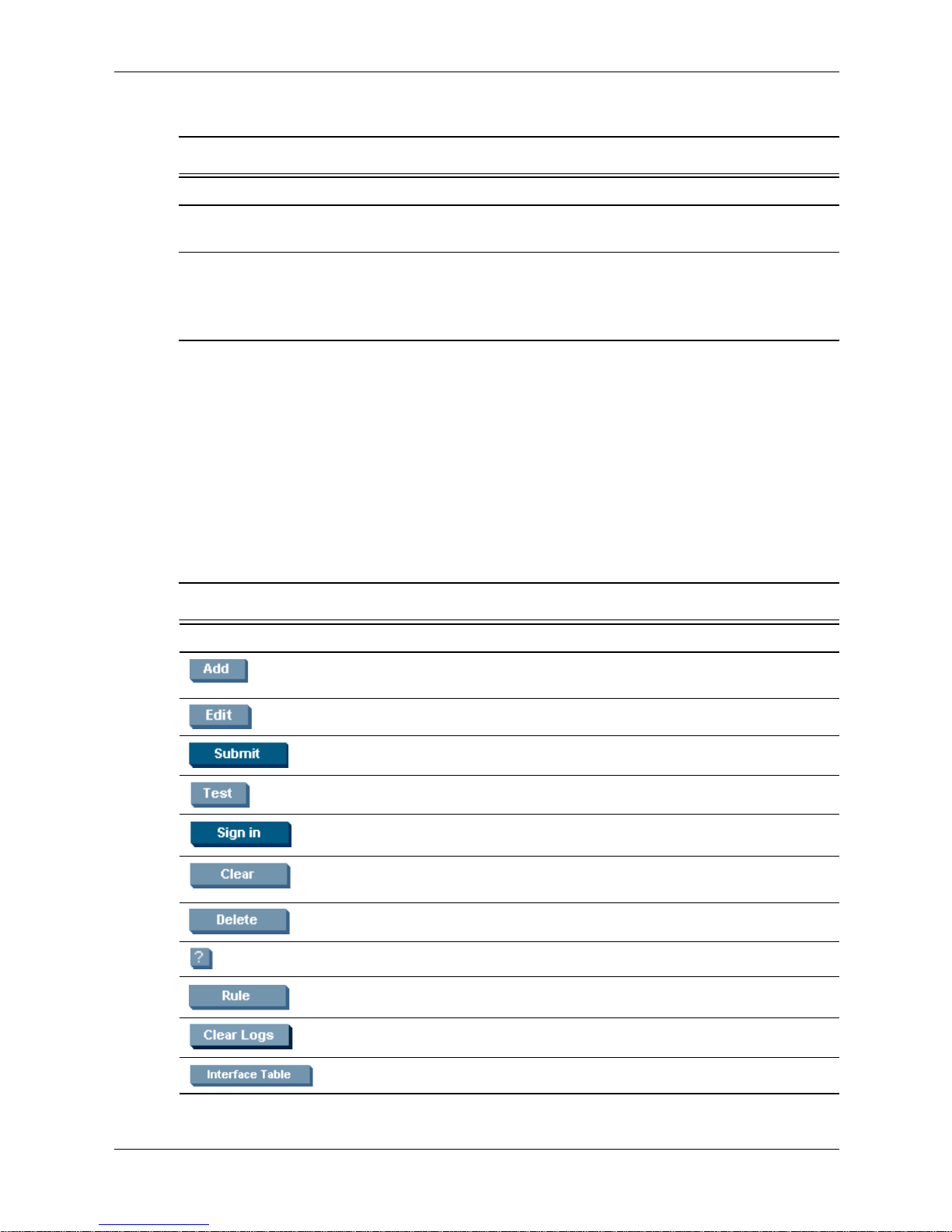
Using the Management Buttons
Device Management buttons and icons provide an easy method of configuring device
information, and include the following:
EWS Configuration Management Buttons
Button Button Name Description
Add Opens a page which creates new
Edit Modifies the configuration settings.
Submit Saves configuration changes to the device.
Test Performs cable tests.
Sign in Signs the user into the EWS.
Clear Clears the user-defined passwords from the
Delete Deletes table and configuration entries.
Help Opens the online help page.
configuration entries.
login password.
Embedded Web System User Guide www.hp.com 1-3
Rule Enables the user to define ACL rules.
Clear Logs Clears system log entries.
Interface Table Opens the MSTP Interface Table.
Page 12
Getting Started
EWS Information Tabs
Link Name Description
Sign Out Signs users out of the EWS.
Save Saves the current device configuration.
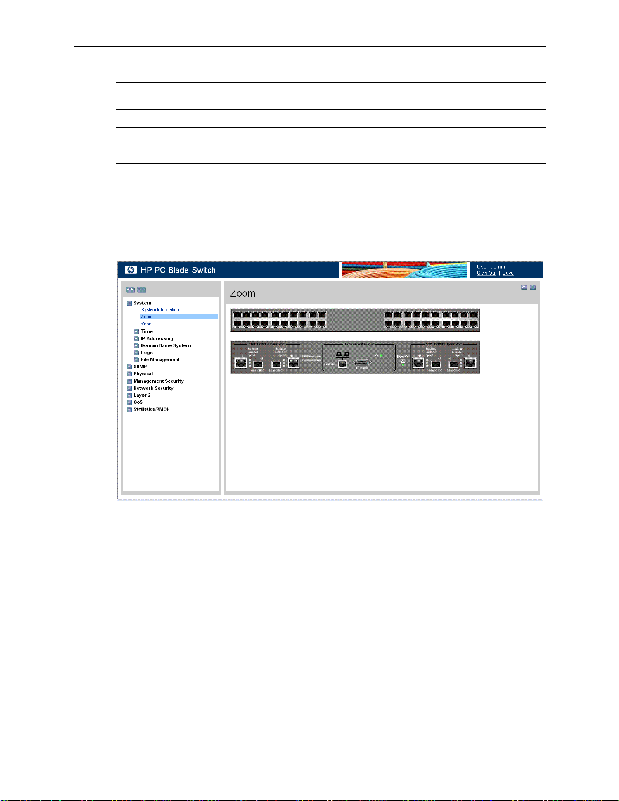
Device Representation
The Zoom View page displays a detailed graphical representation of the device.
To open the Zoom View:
» Click System > Zoom. The Zoom View page opens:
Zoom View
Using Screen and Table Options
The EWS contains screens and tables for configuring devices. This section contains the
following topics:
■ Adding Device Information
■ Modifying Device Information
■ Deleting Device Information
1-4 www.hp.com Embedded Web System User Guide
Page 13
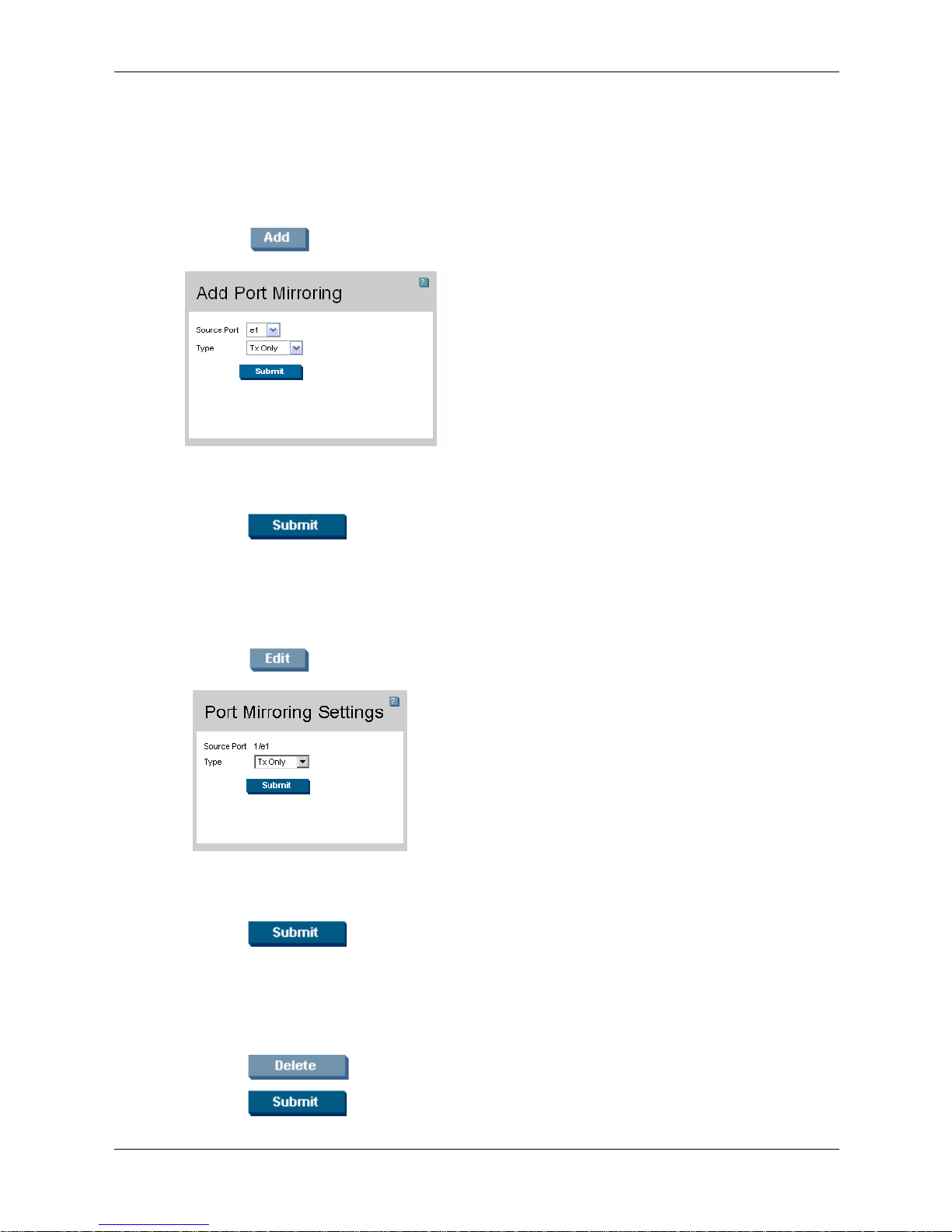
Adding Device Information
User-defined information can be added to specific EWS pages, by opening a new Add page.
To add information to tables or EWS pages:
1. Open an EWS page.
2. Click . An Add page opens, for example, the Add Port Mirroring page:
Add Port Mirroring
3. Define the fields.
Getting Started
4. Click . The configuration information is saved, and the device is updated.
Modifying Device Information
1. Open the EWS page.
2. Select a table entry.
3. Click . A Modify page opens, for example, the Port Mirroring Settings page:
Port Mirroring Settings
4. Define the fields.
5. Click . The fields are modified, and the information is saved to the device.
Deleting Device Information
1. Open the EWS page.
2. Select a table row.
3. Click .
4. Click . The information is deleted, and the device is updated.
Embedded Web System User Guide www.hp.com 1-5
Page 14
Getting Started
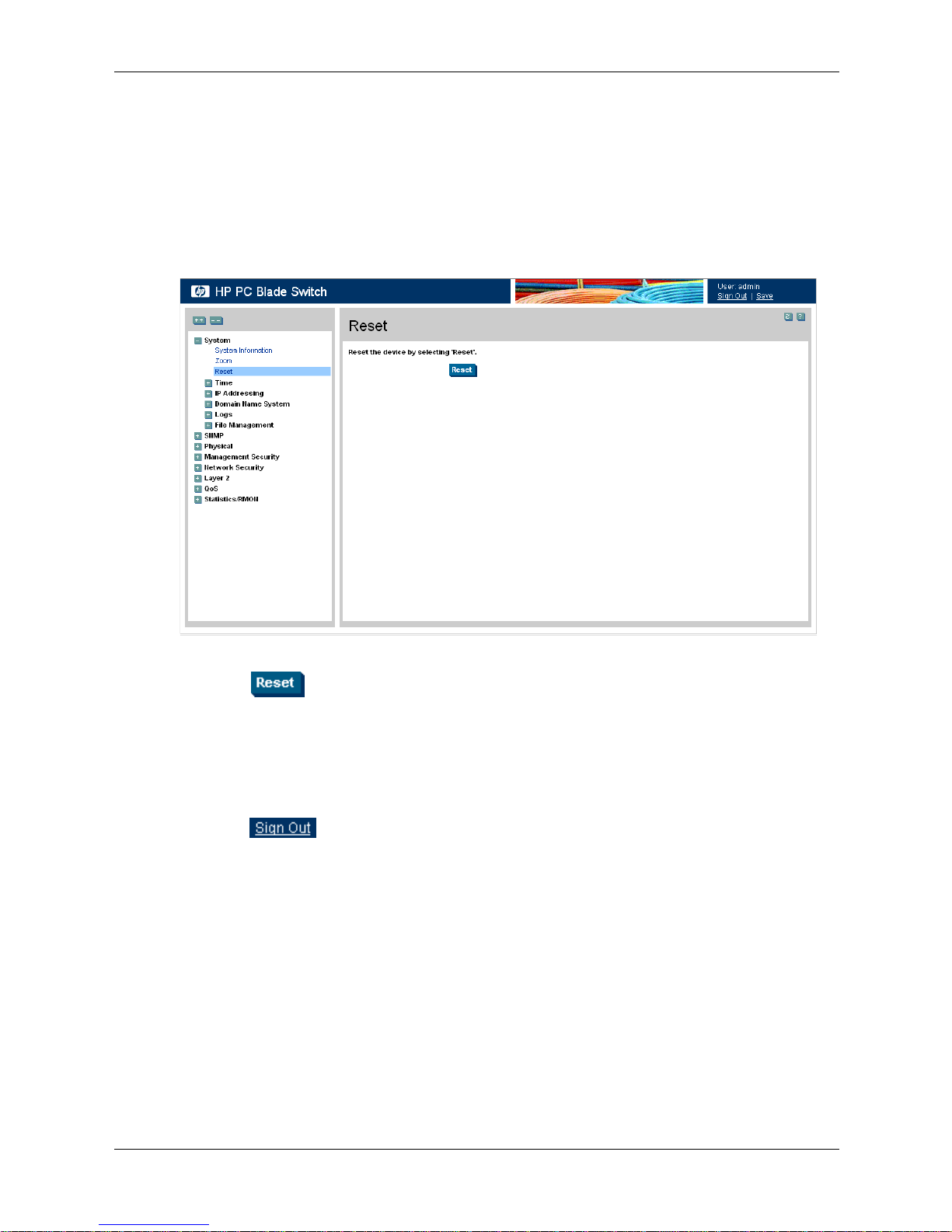
Resetting the Device
The Reset page enables the device to be reset from a remote location. Save all changes to the
Running Configuration file before resetting the device. This prevents the current device
configuration from being lost.
To reset the device:
1. Click System > Reset. The Reset page opens.
Reset
2. Click . The device is reset. After the device is reset, a prompt for a user name and
password displays.
3. Enter a user name and password to reconnect to the Web Interface.
Logging Off the Device
■ Click . The HP PC Blade Switch Home page opens.
1-6 www.hp.com Embedded Web System User Guide
Page 15

2
Defining System Information
The System Information page contains parameters for configuring general device information,
including the System Name, System Location, System Contact, System Object ID, System Up
Time, Base MAC addresses, Hardware Version, Software Version, and Boot Version.
To define the general system information:
1. Click System > System Information. The System Information page opens:
System Information
The System Information page contains the following fields:
■ Model Name — Displays the device model number and name.
■ System Name — Defines the user-defined device name. The field range is 0-160 characters.
■ System Location — Defines the location where the system is currently running. The field
range is 0-160 characters.
■ System Contact — Defines the name of the contact person. The field range is 0-160
characters.
■ System Object ID — Displays the vendor’s authoritative identification of the network
management subsystem contained in the entity.
■ System Up Time — Displays the amount of time since the most recent device reset. The
system time is displayed in the following format: Days, Hours, Minutes, Seconds. For
example, 41 days, 2 hours, 22 minutes, 15 seconds.
■ Base MAC Address — Displays the device MAC address.
Embedded Web System User Guide www.hp.com 2-1
Page 16

Defining System Information
■ Hardware Version — Displays the installed device hardware version number.
■ Software Version — Displays the installed software version number.
■ Boot Version — Displays the current boot version running on the device.
2-2 www.hp.com Embedded Web System User Guide
Page 17

Configuring System Time
This section provides information for configuring system time parameters, including:
■ Configuring Daylight Savings Time
■ Configuring SNTP
Configuring Daylight Savings Time
The System Time page contains fields for defining system time parameters for both the local
hardware clock and the external SNTP clock. If the system time is kept using an external SNTP
clock, and the external SNTP clock fails, the system time reverts to the local hardware clock.
Daylight Savings Time can be enabled on the device.
The following is a list of Daylight Savings Time start and end times in specific countries:
■ Albania — From the last weekend of March until the last weekend of October.
■ Australia — From the end of October until the end of March.
■ Australia - Tasmania — From the beginning of October until the end of March.
3
■ Armenia — From the last weekend of March until the last weekend of October.
■ Austria — From the last weekend of March until the last weekend of October.
■ Bahamas — From April to October, in conjunction with Daylight Savings Time in the
United States.
■ Belarus — From the last weekend of March until the last weekend of October.
■ Belgium — From the last weekend of March until the last weekend of October.
■ Brazil — From the third Sunday in October until the third Saturday in March. During the
period of Daylight Savings Time, Brazilian clocks go forward one hour in most of the
Brazilian southeast.
■ Chile — In Easter Island, from March 9 until October 12. In the rest of the country, from the
first Sunday in March or after March 9.
■ China — China does not use Daylight Savings Time.
■ Canada — From the first Sunday in April until the last Sunday of October. Daylight Savings
Time is usually regulated by provincial and territorial governments. Exceptions may exist in
certain municipalities.
■ Cuba — From the last Sunday of March to the last Sunday of October.
■ Cyprus — From the last weekend of March until the last weekend of October.
■ Denmark — From the last weekend of March until the last weekend of October.
■ Egypt — From the last Friday in April until the last Thursday in September.
■ Estonia — From the last weekend of March until the last weekend of October.
Embedded Web System User Guide www.hp.com 3-1
Page 18

Configuring System Time
■ Finland — From the last weekend of March until the last weekend of October.
■ France — From the last weekend of March until the last weekend of October.
■ Germany — From the last weekend of March until the last weekend of October.
■ Greece — From the last weekend of March until the last weekend of October.
■ Hungary — From the last weekend of March until the last weekend of October.
■ India — India does not use Daylight Savings Time.
■ Iran — From Farvardin 1 until Mehr 1.
■ Iraq — From April 1 until October 1.
■ Ireland — From the last weekend of March until the last weekend of October.
■ Israel — Varies year-to-year.
■ Italy — From the last weekend of March until the last weekend of October.
■ Japan — Japan does not use Daylight Savings Time.
■ Jordan — From the last weekend of March until the last weekend of October.
■ Latvia — From the last weekend of March until the last weekend of October.
■ Lebanon — From the last weekend of March until the last weekend of October.
■ Lithuania — From the last weekend of March until the last weekend of October.
■ Luxembourg — From the last weekend of March until the last weekend of October.
■ Macedonia — From the last weekend of March until the last weekend of October.
■ Mexico — From the first Sunday in April at 02:00 to the last Sunday in October at 02:00.
■ Moldova — From the last weekend of March until the last weekend of October.
■ Montenegro — From the last weekend of March until the last weekend of October.
■ Netherlands — From the last weekend of March until the last weekend of October.
■ New Zealand — From the first Sunday in October until the first Sunday on or after
March 15.
■ Norway — From the last weekend of March until the last weekend of October.
■ Paraguay — From April 6 until September 7.
■ Poland — From the last weekend of March until the last weekend of October.
■ Portugal — From the last weekend of March until the last weekend of October.
■ Romania — From the last weekend of March until the last weekend of October.
■ Russia — From the last weekend of March until the last weekend of October.
■ Serbia — From the last weekend of March until the last weekend of October.
■ Slovak Republic — From the last weekend of March until the last weekend of October.
■ South Africa — South Africa does not use Daylight Savings Time.
■ Spain — From the last weekend of March until the last weekend of October.
■ Sweden — From the last weekend of March until the last weekend of October.
■ Switzerland — From the last weekend of March until the last weekend of October.
3-2 www.hp.com Embedded Web System User Guide
Page 19
Configuring System Time
■ Syria — From March 31 until October 30.
■ Ta iw an — Taiwan does not use Daylight Savings Time.
■ Tu rke y — From the last weekend of March until the last weekend of October.
■ United Kingdom — From the last weekend of March until the last weekend of October.
■ United States of America — From the first Sunday in April at 02:00 until the last Sunday in
October at 02:00.
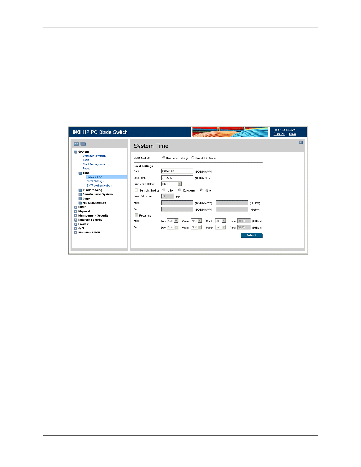
To configure the system clock time:
1. Click System > Time > System Time. The System Time page opens:
System Time
The System Time page contains the following sections:
❏ Clock Source — The source used to set the system clock. The possible field values are:
◆ Use Local Settings — Indicates that the clock is set locally.
◆ Use SNTP Server — Indicates that the system time is set via an SNTP server.
❏ Date — The system date. The field format is DD/MMM/YY. For example, 04/May/05
(May 4, 2005).
❏ Local Time — The system time. The field format is HH:MM:SS. For example,
21:15:03.
❏ Time Zone Offset — The difference between Greenwich Mean Time (GMT) and local
time. For example, the Time Zone Offset for Paris is GMT +1, while the Time Zone
Offset for New York is GMT –5.
❏ Daylight Saving — Enables automatic Daylight Savings Time (DST) on the device
based on the device’s location. There are two types of daylight settings, either by a
specific date in a particular year, or a reoccurring setting irrespective of the year. For a
specific setting in a particular year, complete the Daylight Saving area, and for a
recurring setting, complete the Recurring area. The possible field values are:
◆ USA — The device switches to DST at 2:00 a.m. on the first Sunday in April, and
reverts to standard time at 2:00 a.m. on the last Sunday in October.
Embedded Web System User Guide www.hp.com 3-3
Page 20

Configuring System Time
◆ European — The device switches to DST at 1:00 am on the last Sunday in March
◆ Other — The DST definitions are user-defined based on the device locality. If Other
❏ Time Set Offset — Used for non-USA and European countries to set the amount of time
for DST (in minutes). The default time is 60 minutes.
❏ From — Indicates the time that DST begins in countries other than the USA and Europe,
in the format DD/MMM/YY in one field and HH:MM in another. For example, if DST
begins on October 25, 2007 at 5:00 am, the two fields should be set to 25/Oct/07 and
05:00. The possible field values are:
◆ Date — The date on which DST begins. The field format is DD/MM/YY. DD
◆ Time — The time at which DST begins. The field format is HH:MM. For example,
❏ To — Indicates the time that DST ends in countries other than the USA and Europe, in
the format DD/MMM/YY in one field and HH:MM in another. For example, if DST
ends on March 23, 2008 at midnight, the two fields should be 23/Mar/08 and 00:00. The
possible field values are:
and reverts to standard time at 1:00 am on the last Sunday in October. The European
option applies to EU members and other European countries using the EU standard.
is selected, you must define the From and To fields.
indicates the day in which the time offset begins.The possible field range is 1-31.
MMM indicates the calendar month in which the time offset begins. The possible
field range is Jan-Dec. YY indicates the year in which the time offset begins.
05:30.
◆ Date — The date on which DST ends. The field format is DD/MM/YY. DD
indicates the day in which the time offset ends.The possible field range is 1-31.
MMM indicates the calendar month in which the time offset ends. The possible field
range is Jan-Dec. YY indicates the year in which the time offset ends.
◆ Time — The time at which DST ends. The field format is HH:MM. For example,
05:30.
❏ Recurring — Enables user-defined DST for countries in which DST is constant from
year to year, other than the USA and Europe.
❏ From — The time that DST begins each year. For example, DST begins locally every
first Sunday in April at 00:00 (midnight). The possible field values are:
◆ Day — The day of the week from which DST begins every year. The possible field
range is Sunday-Saturday.
◆ Week — The week within the month from which DST begins every year. The
possible field range is First-Fifth.
◆ Month — The month of the year in which DST begins every year. The possible field
range is Jan-Dec.
◆ Time — The time at which DST begins every year. The field format is HH:MM. For
example, 02:10.
❏ To — The time that DST ends each year. For example, DST ends locally every first
Sunday in October at 00:00 (midnight). The possible field values are:
◆ Day — The day of the week at which DST ends every year. The possible field range
is Sunday-Saturday.
◆ Week — The week within the month at which DST ends every year. The possible
field range is First-Fifth.
3-4 www.hp.com Embedded Web System User Guide
Page 21

◆ Month — The month of the year in which DST ends every year. The possible field
range is Jan-Dec.
◆ Time — The time at which DST ends every year. The field format is HH:MM. For
example, 05:30.
2. Define the Date, Local Time, and Time Zone Offset fields.
3. To configure the device to automatically switch to DST, select Daylight Saving and select
either USA, European, or Other. If you select Other, you must define its From and To
fields. To configure DST parameters that will recur every year, select Recurring and define
its From and To fields.
4. Click . The DST settings are saved, and the device is updated.
Configuring SNTP
The device supports the Simple Network Time Protocol (SNTP). SNTP assures accurate network
device clock time synchronization up to a millisecond. Time synchronization is performed by a
network SNTP server. The device operates only as an SNTP client, and cannot provide time
services to other systems. The device can poll the following server types for the server time:
■ Unicast
Configuring System Time
■ Anycast
■ Broadcast
Time sources are established by stratums. Stratums define the accuracy of the reference clock.
The higher the stratum (where zero is the highest), the more accurate the clock. The device
receives time from stratum 1 and above. The following is an example of stratums:
■ Stratum 0 — A real time clock (such as a GPS system) is used as the time source.
■ Stratum 1 — A server that is directly linked to a Stratum 0 time source is used. Stratum 1
time servers provide primary network time standards.
■ Stratum 2 — The time source is distanced from the Stratum 1 server over a network path.
For example, a Stratum 2 server receives the time over a network link, via NTP, from a
Stratum 1 server.
Information received from SNTP servers is evaluated based on the time level and server type.
SNTP time definitions are assessed and determined by the following time levels:
■ T1 — The time at which the original request was sent by the client.
■ T2 — The time at which the original request was received by the server.
■ T3 — The time at which the server sent the client a reply.
■ T4 — The time at which the client received the server's reply.
Message Digest 5 (MD5) Authentication safeguards device synchronization paths to SNTP
servers. MD5 is an algorithm that produces a 128-bit hash. MD5 is a variation of MD4, and
increases MD4 security. MD5 verifies the integrity of the communication and authenticates the
origin of the communication.
This section contains the following topics:
■ Defining SNTP Global Settings
■ Defining SNTP Authentication
Embedded Web System User Guide www.hp.com 3-5
Page 22
Configuring System Time
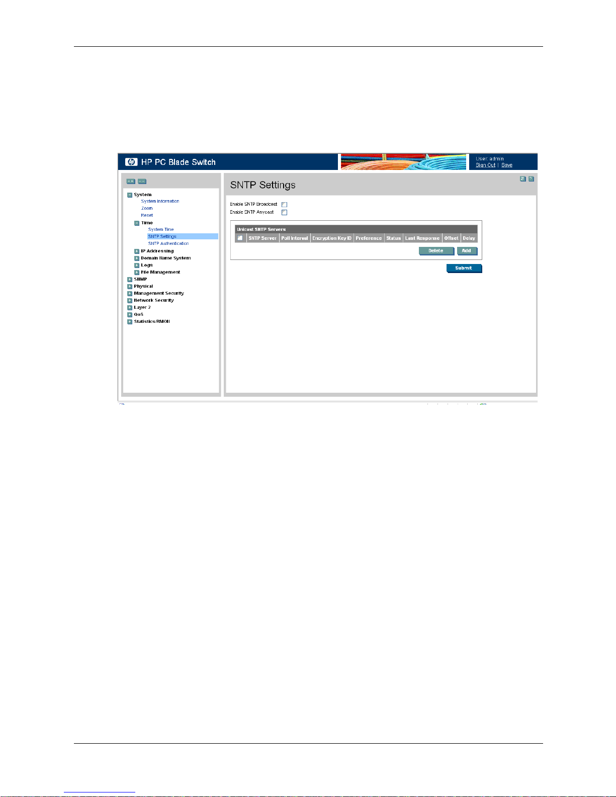
Defining SNTP Global Settings
The SNTP Settings page provides information for defining SNTP parameters globally.
To define SNTP global parameters:
1. Click System > Time > SNTP Settings. The SNTP Settings page opens:
SNTP Settings
The SNTP Settings page contains the following fields:
❏ Enable SNTP Broadcast — If checked, this field enables SNTP broadcast.
❏ Enable SNTP Anycast — If checked, this field enables SNTP Anycast.
❏ SNTP Server — Displays a user-defined SNTP server IP addresses. You can define up
to eight SNTP servers.
❏ Poll Interval — Defines the interval (in seconds) at which the SNTP server is polled for
Unicast information. The Poll Interval default is 1024 seconds.
❏ Encryption Key ID — Indicates if the encryption key identification is used to
authenticate the SNTP server and device. The field value is up to 4294967295.
❏ Preference — Indicates the SNTP server providing SNTP system time information. The
possible field values are:
◆ Primary — Indicates the primary server provides SNTP information.
◆ Secondary — Indicates the backup server provides SNTP information.
❏ Status — Indicates the SNTP server operating status. The possible field values are:
◆ Up — Indicates the SNTP server is currently operating normally.
◆ Down — Indicates that a SNTP server is currently not available. For example, the
SNTP server is currently not connected or is currently down.
3-6 www.hp.com Embedded Web System User Guide
Page 23
◆ In progress — Indicates the SNTP server is currently sending or receiving SNTP
information.
◆ Unknown — Indicates the progress of the SNTP information currently being sent is
unknown. For example, the device is currently looking for an interface.
❏ Last Response — Displays the last time a response was received from the SNTP server.
❏ Offset — Indicates the time difference between the device local clock and the acquired
time from the SNTP server.
❏ Delay — Indicates the amount of time it takes for a device request to reach the SNTP
server.
2. Define the fields.
3. Click . The SNTP global settings are defined, and the device is updated.
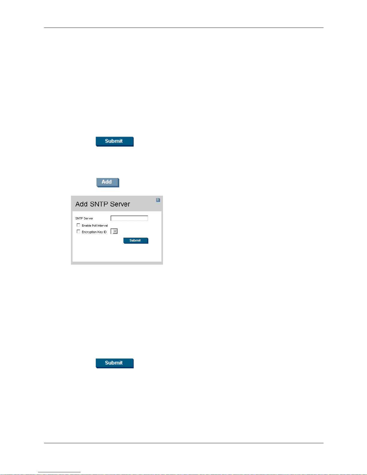
Defining SNTP Servers
To add an SNTP server:
1. Click . The Add SNTP Server page opens:
Configuring System Time
Add SNTP Server
In addition to the fields in the SNTP Settings page, the Add SNTP Server page contains the
following additional field:
❏ Enable Poll Interval — Indicates if the device polls the SNTP server. The possible field
values are:
◆ Checked — Enables polling the SNTP server for SNTP information.
◆ Unchecked — Disables polling the server for SNTP information. This is the default
value.
2. Define the SNTP Server, Enable Poll Interval, and Encryption Key ID fields.
3. Click . The SNTP server is added, and the device is updated.
Embedded Web System User Guide www.hp.com 3-7
Page 24
Configuring System Time
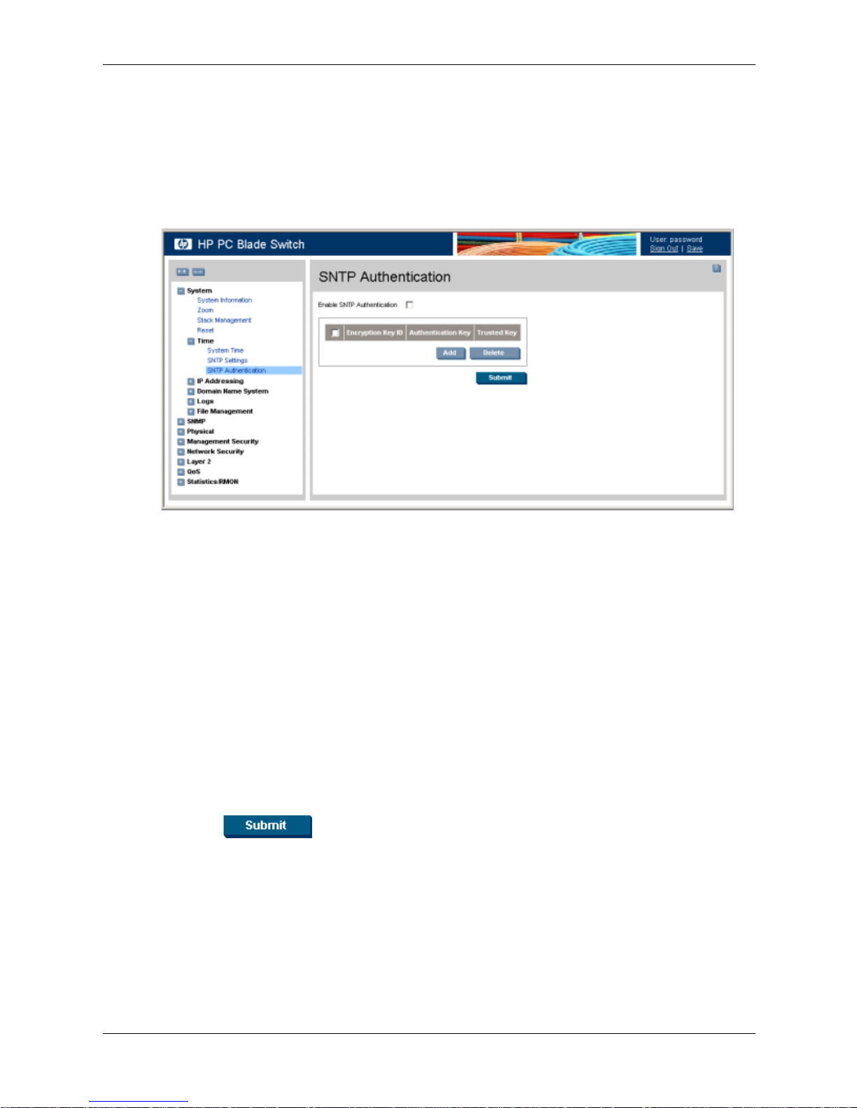
Defining SNTP Authentication
The SNTP Authentication page provides parameters for defining the means by which the SNTP
server is authenticated.
To define SNTP authentication:
1. Click System > Time > SNTP Authentication. The SNTP Authentication page opens:
SNTP Authentication
The SNTP Authentication page contains the following fields:
❏ Enable SNTP Authentication — Indicates if authenticating an SNTP session between
the device and an SNTP server is enabled on the device. The possible field values are:
◆ Checked — Authenticates SNTP sessions between the device and the SNTP server.
◆ Unchecked — Disables authenticating SNTP sessions between the device and the
SNTP server.
❏ Encryption Key ID — Indicates if the encryption key identification is used to
authenticate the SNTP server and the device. The field value is up to 4294967295.
❏ Authentication Key — Indicates the key used for authentication.
❏ Tr us te d Ke y — Indicates the encryption key used (Unicast/Anycast) or elected
(Broadcast) to authenticate the SNTP server.
2. Select the Enable SNTP Authentication field.
3. Click . SNTP Authentication is defined, and the device is updated.
3-8 www.hp.com Embedded Web System User Guide
Page 25
Configuring System Time
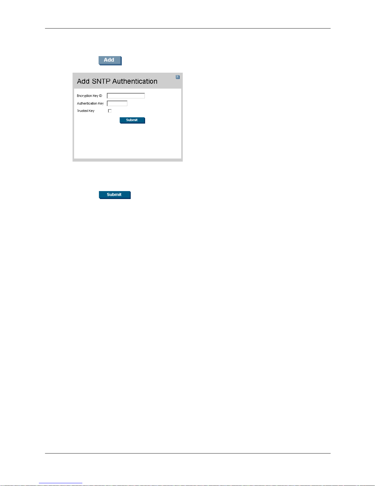
To define SNTP authentication parameters:
1. Click . The SNTP Authentication page opens:
Add SNTP Authentication
2. Define the Encryption Key ID, Authentication Key, and Trust e d Key fields.
3. Click . The SNTP Authentication Key is added, and the device is updated
Embedded Web System User Guide www.hp.com 3-9
Page 26

Configuring System Time
3-10 www.hp.com Embedded Web System User Guide
Page 27

Configuring Device Security
This section provides access to security pages that contain fields for setting security parameters
for ports, device management methods, users, and server security. This section contains the
following topics:
■ Configuring Authentication Methods
■ Configuring Network Security
Configuring Authentication Methods
This section provides information for configuring device authentication methods. This section
includes the topics:
■ Defining Access Profiles
■ Defining Profile Rules
■ Defining Authentication Profiles
■ Mapping Authentication Methods
4
■ Defining RADIUS Settings
■ Defining TACACS+ Authentication
■ Configuring Passwords
Defining Access Profiles
Access profiles are profiles and rules for accessing the device. Access to management functions
can be limited to user groups. User groups are defined for interfaces according to IP addresses or
IP subnets. Access profiles contain management methods for accessing and managing the device.
The device management methods include:
■ All
■ Te lnet
■ Secure Telnet (SSH)
■ HTTP
■ SNMP
■ HTTPS
Management access to different management methods may differ between user groups. For
example, User Group 1 can access the switch module only via an HTTPS session, while User
Group 2 can access the switch module using both HTTPS and Telnet sessions. The Access
Profiles page contains the currently configured access profiles and their activity status.
Assigning an access profile to an interface denies access using other interfaces. If an access
profile is assigned to any interface, the device can be accessed by all interfaces.
Embedded Web System User Guide www.hp.com 4-1
Page 28
Configuring Device Security
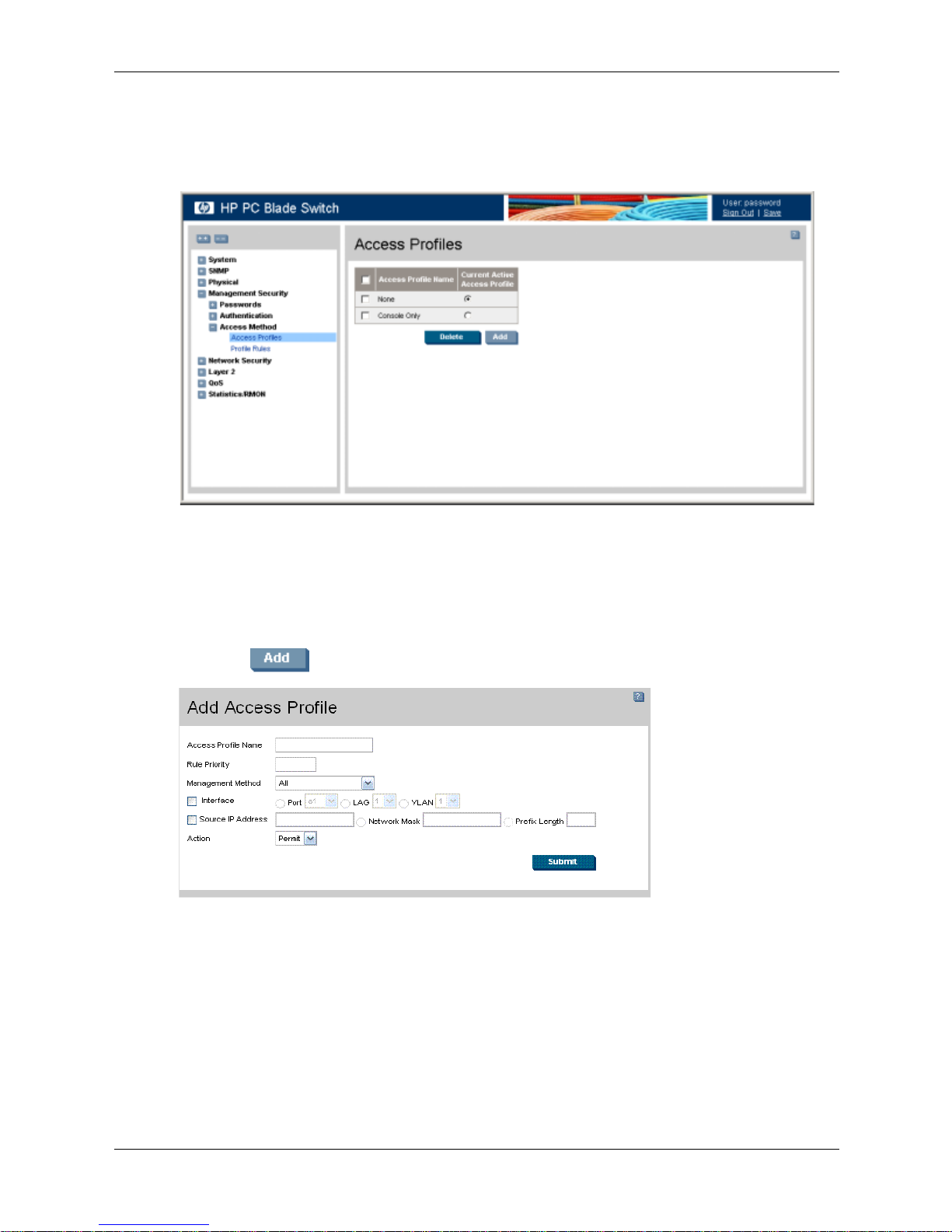
To configure access profiles:
1. Click Management Security > Access Method > Access Profiles. The Access Profiles page
opens:
Access Profiles
The Access Profiles page contains the following fields:
❏ Access Profile Name — Defines the access profile name. The access profile name can
contain up to 32 characters.
❏ Current Active Access Profile — Defines the access profile currently active.
2. Click . The Add Access Profile page opens:
Add Access Profile
In addition to the fields in the Access Profiles page, the Add Access Profile page contains the
following fields:
❏ Rule Priority — Defines the rule priority. When the packet is matched to a rule, user
groups are either granted permission or denied device management access. The rule
number is essential to matching packets to rules, as packets are matched on a first-fit
basis. The rule priorities are assigned in the Profile Rules.
❏ Management Method — Defines the management method for which the rule is defined.
Users with this access profile can access the device using the management method
selected. The possible field values are:
4-2 www.hp.com Embedded Web System User Guide
Page 29

Configuring Device Security
◆ All — Assigns all management methods to the rule.
◆ Te ln et — Assigns Telnet access to the rule. If selected, users accessing the device
using Telnet meeting access profile criteria are permitted or denied access to the
device.
◆ Secure Telnet (SSH) — Assigns SSH access to the rule. If selected, users accessing
the device using Telnet, meeting access profile criteria, are permitted or denied
access to the device.
◆ HTTP — Assigns HTTP access to the rule. If selected, users accessing the device
using HTTP, meeting access profile criteria, are permitted or denied access to the
device.
◆ Secure HTTP (HTTPS) — Assigns HTTPS access to the rule. If selected, users
accessing the device using HTTPS, meeting access profile criteria, are permitted or
denied access to the device.
◆ SNMP — Assigns SNMP access to the rule. If selected, users accessing the device
using SNMP, meeting access profile criteria, are permitted or denied access to the
device.
❏ Interface — Defines the interface on which the access profile is defined. The possible
field values are:
◆ Port — Specifies the port on which the access profile is defined.
◆ LAG — Specifies the LAG on which the access profile is defined.
◆ VLAN — Specifies the VLAN on which the access profile is defined.
❏ Source IP Address — Defines the interface source IP address to which the access
profile applies. The Source IP Address field is valid for a subnetwork.
◆ Network Mask — Defines the IP subnetwork mask.
◆ Prefix Length — Defines the number of bits that comprises the source IP address
prefix, or the network mask of the source IP address.
❏ Action — Defines the action attached to the rule. The possible field values are:
◆ Permit — Permits access to the device.
◆ Deny — Denies access to the device. This is the default.
3. Define the fields.
4. Click . The access profile is created, and the device is updated.
Embedded Web System User Guide www.hp.com 4-3
Page 30
Configuring Device Security
Defining Profile Rules
Access profiles can contain up to 128 rules that determine which users can manage the switch
module, and by which methods. Users can also be blocked from accessing the device. Rules are
composed of filters including:
■ Rule Priority
■ Interface
■ Management Method
■ IP Address
■ Prefix Length
■ Forwarding Action
The rule order is essential as packets are matched on a first-fit basis.
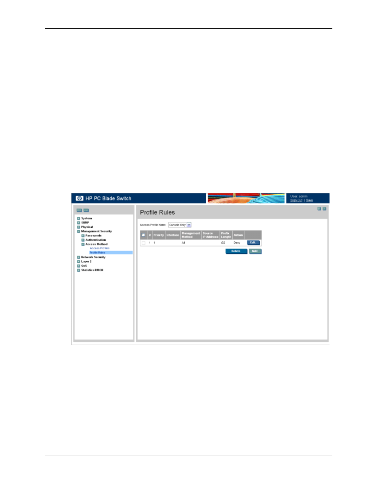
To define profile rules:
1. Click Management Security > Access Method > Profile Rules. The Profile Rules page
opens:
Profile Rules
The Profile Rules page contains the following fields:
❏ Access Profile Name — Displays the access profile to which the rule is attached.
❏ Priority — Defines the rule priority. When the packet is matched to a rule, user groups
are either granted or denied device management access. The rule number is essential to
matching packets to rules, as packets are matched on a first-fit basis.
❏ Interface — Indicates the interface type to which the rule applies. The possible field
values are:
◆ Port — Attaches the rule to the selected port.
◆ LAG — Attaches the rule to the selected LAG.
4-4 www.hp.com Embedded Web System User Guide
Page 31

Configuring Device Security
◆ VLAN — Attaches the rule to the selected VLAN.
❏ Management Method — Defines the management method for which the rule is defined.
Users with this access profile can access the device using the management method
selected. The possible field values are:
◆ All — Assigns all management methods to the rule.
◆ Te ln et — Assigns Telnet access to the rule. If selected, users accessing the device
using Telnet, meeting access profile criteria, are permitted or denied access to the
device.
◆ Secure Telnet (SSH) — Assigns SSH access to the rule. If selected, users accessing
the device using Telnet, meeting access profile criteria, are permitted or denied
access to the device.
◆ HTTP — Assigns HTTP access to the rule. If selected, users accessing the device
using HTTP, meeting access profile criteria, are permitted or denied access to the
device.
◆ Secure HTTP (HTTPS) — Assigns HTTPS access to the rule. If selected, users
accessing the device using HTTPS, meeting access profile criteria, are permitted or
denied access to the device.
◆ SNMP — Assigns SNMP access to the rule. If selected, users accessing the device
using SNMP, meeting access profile criteria, are permitted or denied access to the
device.
❏ Source IP Address — Defines the interface source IP address to which the rule applies.
❏ Prefix Length — Defines the number of bits that comprise the source IP address prefix,
or the network mask of the source IP address.
❏ Action —Defines the action attached to the rule. The possible field values are:
◆ Permit — Permits access to the device.
◆ Deny — Denies access to the device. This is the default.
2. Click .
Add Profile Rule
3. Define the Access Profile Name, Priority, Management Method, Interface, Source IP
Address, Network Mask or Prefix Length, and Action fields.
4. Click . The profile rule is added to the access profile, and the device is
updated.
Embedded Web System User Guide www.hp.com 4-5
Page 32

Configuring Device Security
To modify a profile rule:
1. Click Management Security > Access Method > Profile Rules. The Profile Rules page
opens.
2. Select a Profile Rule entry.
3. Click . The Profile Rule Settings page opens:
Edit Profile Rule Settings
4. Modify the fields.
5. Click . The profile rule is modified, and the device is updated.
Defining Authentication Profiles
Authentication profiles allow network administrators to assign authentication methods for user
authentication. User authentication can be performed either locally or on an external server. User
authentication occurs in the order the methods are selected. If the first authentication method is
not available, the next selected method is used. For example, if the selected authentication
methods are RADIUS and Local, and the RADIUS server is not available, then the user is
authenticated locally.
4-6 www.hp.com Embedded Web System User Guide
Page 33

Configuring Device Security
To define authentication profiles:
1. Click Management Security > Authentication > Authentication Profiles. The
Authentication Profiles page opens.
:
Authentication Profiles
The Authentication Profiles page contains the following sections:
❏ The Login Authentication Profiles section allows network administrators to select the
authentication method by which system users are logged onto the device.
❏ The Enable Authentication Profiles section allows network administrators to select the
method by which users are enabled on the system.
Each section on the Authentication Profiles page contains the following fields:
❏ Profile Name — Contains a list of user-defined authentication profile lists to which
user-defined authentication profiles are added.
❏ Methods — Defines the user authentication methods. The possible field values are:
◆ None — Assigns no authentication method to the authentication profile.
◆ Local — Authenticates the user at the device level. The device checks the user name
and password for authentication.
◆ RADIUS — Authenticates the user at the RADIUS server. For more information,
see “Defining RADIUS Settings.”
◆ TACACS + — Authenticates the user at the TACACS+ server. For more information,
see “Defining TACACS+ Authentication.”
◆ Line — Authenticates the user using a line password.
◆ Enable — Authenticates the user using an enable password.
Embedded Web System User Guide www.hp.com 4-7
Page 34

Configuring Device Security
2. Click . The Add Authentication Profile page opens:
Add Authentication Profile
3. Define the Profile Name and Authentication Methods fields.
4. Click . The authentication profile is defined, and the device is updated.
To modify an authentication profile:
1. Click Management Security > Authentication > Authentication Profiles. The
Authentication Profiles page opens.
2. Select an Authentication Profile entry.
3. Click . The Authentication Profile Settings page opens:
Authentication Profile Settings
4. Select an authentication method from the Optional Methods list.
5. Click . The authentication method is selected, and the device is updated.
4-8 www.hp.com Embedded Web System User Guide
Page 35

Mapping Authentication Methods
After authentication profiles are defined, they can be applied to management access methods. For
example, console users can be authenticated by Authentication Profile List 1, while Telnet users
are authenticated by Authentication Method List 2.
Authentication methods are selected by using arrows to move the methods to the Selected
Methods list. The order in which the methods are selected is the order by which the
authentication methods are used.
To map authentication methods:
1. Click Management Security > Authentication > Authentication Mapping. The
Authentication Mapping page opens:
Configuring Device Security
Authentication Mapping
The Authentication Mapping page contains the following fields:
❏ Console — Indicates that authentication profiles are used to authenticate console users.
❏ Te ln et — Indicates that authentication profiles are used to authenticate Telnet users.
❏ Secure Telnet (SSH) — Indicates that authentication profiles are used to authenticate
Secure Shell (SSH) users. SSH provides clients secure and encrypted remote
connections to a device.
❏ Secure HTTP — Indicates that authentication methods are used for Secure HTTP
access. Possible field values are:
◆ None — Indicates that no authentication method is used for access.
◆ Local — Indicates that authentication occurs locally.
◆ RADIUS — Indicates that authentication occurs at the RADIUS server.
◆ Line — Indicates that authentication uses a line password.
◆ Enable — Indicates that authentication uses an enable password.
Embedded Web System User Guide www.hp.com 4-9
Page 36

Configuring Device Security
◆ Local, RADIUS — Indicates that authentication first occurs locally. If
authentication cannot be verified locally, the RADIUS server authenticates the
management method. If the RADIUS server cannot authenticate the management
method, the session is blocked.
◆ RADIUS, Local — Indicates that authentication first occurs at the RADIUS server.
If authentication cannot be verified at the RADIUS server, the session is
authenticated locally. If the session cannot be authenticated locally, the session is
blocked.
◆ Local, RADIUS, None — Indicates that authentication first occurs locally. If
authentication cannot be verified locally, the RADIUS server authenticates the
management method. If the RADIUS server cannot authenticate the management
method, the session is permitted.
◆ RADIUS, Local, None — Indicates that authentication first occurs at the RADIUS
server. If authentication cannot be verified at the RADIUS server, the session is
authenticated locally. If the session cannot be authenticated locally, the session is
permitted.
◆ Local, TACACS+ — Indicates that authentication first occurs locally. If
authentication cannot be verified locally, the TACACS+ server authenticates the
management method. If the TACACS+ server cannot authenticate the management
method, the session is blocked.
◆ TACACS +, Local — Indicates that authentication first occurs at the TACACS+
server. If authentication cannot be verified at the TACACS+ server, the session is
authenticated locally. If the session cannot be authenticated locally, the session is
blocked.
◆ Local, TAC ACS+ , None — Indicates that authentication first occurs locally. If
authentication cannot be verified locally, the TACACS+ server authenticates the
management method. If the TACACS+ server cannot authenticate the management
method, the session is permitted.
◆ TACACS +, Local, None — Indicates that authentication first occurs at the
TACACS+ server. If authentication cannot be verified at the TACACS+ server, the
session is authenticated locally. If the session cannot be authenticated locally, the
session is permitted.
❏ HTTP — Indicates that authentication methods are used for HTTP access. Possible field
values are:
◆ None — Indicates that no authentication method is used for access.
◆ Local — Indicates that authentication occurs locally.
◆ RADIUS — Indicates that authentication occurs at the RADIUS server.
◆ Line — Indicates that authentication uses a line password.
◆ Enable — Indicates that authentication uses an enable password.
◆ Local, RADIUS — Indicates that authentication first occurs locally. If
authentication cannot be verified locally, the RADIUS server authenticates the
management method. If the RADIUS server cannot authenticate the management
method, the session is blocked.
4-10 www.hp.com Embedded Web System User Guide
Page 37

Configuring Device Security
◆ RADIUS, Local — Indicates that authentication first occurs at the RADIUS server.
If authentication cannot be verified at the RADIUS server, the session is
authenticated locally. If the session cannot be authenticated locally, the session is
blocked.
◆ Local, RADIUS, None — Indicates that authentication first occurs locally. If
authentication cannot be verified locally, the RADIUS server authenticates the
management method. If the RADIUS server cannot authenticate the management
method, the session is permitted.
◆ RADIUS, Local, None — Indicates that authentication first occurs at the RADIUS
server. If authentication cannot be verified at the RADIUS server, the session is
authenticated locally. If the session cannot be authenticated locally, the session is
permitted.
◆ Local, TACACS+ — Indicates that authentication first occurs locally. If
authentication cannot be verified locally, the TACACS+ server authenticates the
management method. If the TACACS+ server cannot authenticate the management
method, the session is blocked.
◆ TACACS+, Local — Indicates that authentication first occurs at the TACACS+
server. If authentication cannot be verified at the TACACS+ server, the session is
authenticated locally. If the session cannot be authenticated locally, the session is
blocked.
◆ Local, TACACS+, None — Indicates that authentication first occurs locally. If
authentication cannot be verified locally, the TACACS+ server authenticates the
management method. If the TACACS+ server cannot authenticate the management
method, the session is permitted.
◆ TACACS+, Local, None — Indicates that authentication first occurs at the
TACACS+ server. If authentication cannot be verified at the TACACS+ server, the
session is authenticated locally. If the session cannot be authenticated locally, the
session is permitted.
2. Define the Console, Telnet, and Secure Telnet (SSH) fields.
3. Map the authentication method in the Secure HTTP selection box.
4. Map the authentication method in the HTTP selection box.
5. Click . The authentication mapping is saved, and the device is updated.
Defining TACACS+ Authentication
Terminal Access Controller Access Control System (TACACS+) provides centralized security
user access validation. The system supports up to four TACACS+ servers.
TACACS+ provides a centralized user management system, while still retaining consistency with
RADIUS and other authentication processes. TACACS+ provides the following services:
■ Authentication — Provides authentication during login and using user names and
user-defined passwords.
■ Authorization — Performed at login. Once the authentication session is completed, an
authorization session starts using the authenticated user name.
The TACACS+ protocol ensures network integrity through encrypted protocol exchanges
between the client and TACACS+ server.
Embedded Web System User Guide www.hp.com 4-11
Page 38

Configuring Device Security
The TACACS+ default parameters are user-assigned defaults. The default settings are applied to
newly defined TACACS+ servers. If default values are not defined, the system defaults are
applied to the new TACACS+ servers.
To define TACACS+ authentication settings:
1. Click Management Security > Authentication > TACACS+. The TACACS+ page opens:
TACACS+
This image may not contain all possible fields for this page. The complete list is provided in the
✎
following bullets.
The Default Parameters section contains the following fields:
❏ Source IP Address — Defines the default device source IP address used for the
TACACS+ session between the device and the TACACS+ server.
❏ Key String — Defines the default authentication and encryption key for TACACS+
communication between the device and the TACACS+ server. This key must match the
encryption used on the TACACS+ server.
❏ Timeout for Reply — Defines the amount of time in seconds that passes before the
connection between the device and the TACACS+ times out. The field range is 1-30
seconds.
The TACACS+ page also contains the following fields:
❏ Host IP Address — Defines the TACACS+ Server IP address.
❏ Priority — Defines the order in which the TACACS+ servers are used. The field range is
0-65535. The default is 0.
❏ Source IP Address — Defines the device source IP address used for the TACACS+
session between the device and the TACACS+ server.
❏ Authentication Port — Defines the port number on which the TACACS+ session
occurs. The default port is 49.
4-12 www.hp.com Embedded Web System User Guide
Page 39

Configuring Device Security
❏ Timeout for Reply — Defines the amount of time in seconds that passes before the
connection between the device and the TACACS+ times out. The field range is 1-1000
seconds.
❏ Single Connection — Maintains a single open connection between the device and the
TACACS+ server. The possible field values are:
◆ Enable — Enables a single connection.
◆ Disable — Disables a single connection.
❏ Status — Indicates the connection status between the device and the TACACS+ server.
The possible field values are:
◆ Connected — Indicates there is currently a connection between the device and the
TACACS+ server.
◆ Not Connected — Indicates there is not currently a connection between the device
and the TACACS+ server.
2. Define the Default Parameters.
3. Click . The parameters are set for the TACACS+ server and the device is
updated.
To add a new host:
1. Click . The Add TACACS Host page opens:
Add TACACS Host
2. Define the Host IP Address, Priority, Source IP Address, Key String, Authentication
Port, Timeout for Reply, and Single Connection fields.
3. Click . The TACACS host is defined, and the device is updated.
To modify TACACS host settings:
1. Click Management Security >Authentication > TACACS+. The TACACS+ page opens.
2. Select a TACACS server entry.
Embedded Web System User Guide www.hp.com 4-13
Page 40

Configuring Device Security
3. Click . The TACACS Host Settings page opens:
TACACS Host Settings
4. Define the Priority, Source IP Address, Key String, Authentication Port, Timeout for
Reply, and Single Connection fields.
5. Click . The TACACS host settings are saved, and the device is updated.
Defining RADIUS Settings
Remote Authorization Dial-In User Service (RADIUS) servers provide additional security for
networks. RADIUS servers provide a centralized authentication method for web access. The
default parameters are user-defined, and are applied to newly defined RADIUS servers. If new
default parameters are not defined, the system default values are applied to newly defined
RADIUS servers.
To configure RADIUS servers:
1. Click Management Security > Authentication > RADIUS. The RADIUS page opens:
4-14 www.hp.com Embedded Web System User Guide
Page 41

RADIUS
Configuring Device Security
The RADIUS page contains the following fields:
❏ Default Retries — Defines the number of transmitted requests sent to the RADIUS
server before a failure occurs. Possible field values are 1-10. The default value is 3.
❏ Default Timeout for Reply — Defines the amount of time (in seconds) the device waits
for an answer from the RADIUS server before retrying the query, or switching to the
next server. Possible field values are 1-30. The default value is 3.
❏ Default Dead Time — Defines the default amount of time (in minutes) that a RADIUS
server is bypassed for service requests. The range is 0-2000. The default value is 0.
❏ Default Key String — Defines the default key string used for authenticating and
encrypting all RADIUS communications between the device and the RADIUS server.
This key must match the RADIUS encryption.
❏ Source IP Address — Defines the default IP address of a device accessing the RADIUS
server.
The RADIUS page also contains the following fields:
❏ IP Address — Lists the RADIUS server IP addresses.
❏ Priority — Displays the RADIUS server priority. The possible values are 1-65535,
where 1 is the highest value. The RADIUS server priority is used to configure the server
query order.
❏ Authentication Port — Identifies the authentication port. The authentication port is
used to verify the RADIUS server authentication. The authenticated port default is 1812.
❏ Number of Retries — Defines the number of transmitted requests sent to the RADIUS
server before a failure occurs. The possible field values are 1-10. The default value is 3.
❏ Timeout for Reply — Defines the amount of time (in seconds) the device waits for an
answer from the RADIUS server before retrying the query, or switching to the next
server. The possible field values are 1-30. The default value is 3.
Embedded Web System User Guide www.hp.com 4-15
Page 42

Configuring Device Security
❏ Dead Time — Defines the amount of time (in minutes) that a RADIUS server is
bypassed for service requests. The range is 0-2000. The default is 0 minutes.
❏ Key String — Defines the default key string used for authenticating and encrypting all
RADIUS communications between the device and the RADIUS server. This key must
match the RADIUS encryption.
❏ Source IP Address — Defines the source IP address that is used for communication
with RADIUS servers.
❏ Usage Type — Specifies the RADIUS server authentication type. The default value is
All. The possible field values are:
◆ Log in — Indicates the RADIUS server is used for authenticating user name and
passwords.
◆ 802.1X — Indicates the RADIUS server is used for 802.1X authentication.
◆ All — Indicates the RADIUS server is used for authenticating user names and
passwords, and 802.1X port authentication.
2. Click . The Add RADIUS Server page opens:
Add RADIUS Server
3. Define the Host IP Address, Priority, Authentication Port, Timeout for Reply, Dead
Time, and Usage Type fields.
4. Click . The RADIUS server is added, and the device is updated.
To modify RADIUS server settings:
1. Click Management Security > Authentication > RADIUS. The RADIUS page opens.
2. Select a RADIUS Server entry.
4-16 www.hp.com Embedded Web System User Guide
Page 43

Configuring Device Security
3. Click . The RADIUS Server Settings page opens:
RADIUS Server Settings
4. Define the IP Address, Priority, Authentication Port, Timeout for Reply, Dead Time,
Key String, Source IP Address, and Usage Type fields.
5. Click . The RADIUS server settings are saved, and the device is updated.
Configuring Passwords
This section contains information for defining device passwords, and includes the following
topics:
■ Defining Local Users
■ Defining Line Passwords
■ Defining Enable Passwords
Defining Local Users
Network administrators can define users, passwords, and access levels for users using the Local
Users page.
Creating a new user with the same name as an existing user overwrites the old user, including the
✎
Admin account.
Embedded Web System User Guide www.hp.com 4-17
Page 44

Configuring Device Security
To define local users:
1. Click Management Security > Passwords > Local Users. The Local Users page opens:
Local Users
The Local Users page contains the following fields:
❏ User Name — Displays the user name.
❏ Access Level — Displays the user access level. The lowest user access level is 1 and the
highest is 15. Users with access level 15 are Privileged Users. The possible field values
are:
◆ Configuration — Provides configuration device privileges.
◆ Monitoring — Provides device Read and Read/Write privileges.
2. Click . The Add Local User page opens:
Add Local User
In addition to the fields in the Local Users page, the Add Local User page contains the following
fields:
❏ Password — Defines the local user password. Local user passwords can contain up to
159 characters.
4-18 www.hp.com Embedded Web System User Guide
Page 45

Configuring Device Security
❏ Confirm Password — Verifies the password.
To modify the settings for a local user:
1. Click Management Security > Passwords > Local Users. The Local Users page opens.
2. Select a Local User entry.
3. Click . The Local User Settings page opens:
Local User Settings
4. Define the User Name, Access Level, Password, and Confirm Password fields.
5. Click . The local user settings are defined, and the device is updated.
Defining Line Passwords
Network administrators can define line passwords in the Line Password page. After the line
password is defined, a management method is assigned to the password. The device can be
accessed using the following methods:
■ Console Passwords
■ Te ln e t Pass w o r ds
■ Secure Telnet Passwords
To define line passwords:
Embedded Web System User Guide www.hp.com 4-19
Page 46

Configuring Device Security
1. Click Management Security > Passwords > Line Password. The Line Password page
opens:
Line Password
The Line Password page contains the following fields:
❏ Console Line Password — Defines the line password for accessing the device using a
Console session. Passwords can contain a maximum of 159 characters.
❏ Telnet Line Password — Defines the line password for accessing the device using a
Telnet session. Passwords can contain a maximum of 159 characters.
❏ Secure Telnet Line Password — Defines the line password for accessing the device
using a secure Telnet session. Passwords can contain a maximum of 159 characters.
❏ Confirm Password — Confirms the new line password. The password appears in the
***** format.
2. Define the Console Line Password, Telnet Line Password, and Secure Telnet Line
Password fields.
3. Redefine the Confirm Password field for each of the passwords defined in the previous
steps to verify the passwords.
4. Click . The line passwords are saved, and the device is updated.
4-20 www.hp.com Embedded Web System User Guide
Page 47

Defining Enable Passwords
The Enable Password page sets a local password for a particular access level.
To enable passwords:
1. Click Management Security > Passwords > Enable Password. The Enable Password page
opens:
Configuring Device Security
Enable Password
The Enable Password page contains the following fields:
❏ Level — Defines the access level associated with the enable password. Possible field
values are 1 and 15.
❏ Password — Defines the enable password.
❏ Confirm Password — Confirms the new enable password. The password appears in the
***** format.
2. Define the Level, Password, and Confirm Password fields.
3. Click . The enable password is defined, and the device is updated.
Embedded Web System User Guide www.hp.com 4-21
Page 48

Configuring Device Security
Configuring Network Security
Network security manages both access control lists and locked ports. This section contains the
following topics:
■ Network Security Overview
■ Defining Port Authentication Properties
■ Defining Port Authentication
■ Configuring Traffic Control
Network Security Overview
This section provides an overview of network security and contains the following topics:
■ Port-Based Authentication
■ Advanced Port-Based Authentication
Port-Based Authentication
Port-based authentication authenticates users on a per-port basis using an external server. Only
authenticated and approved system users can transmit and receive data. Ports are authenticated
via the RADIUS server using the Extensible Authentication Protocol (EAP). Port-based
authentication includes:
■ Authenticators — Specifies the device port which is authenticated before permitting system
access.
■ Supplicants — Specifies the host connected to the authenticated port requesting to access
the system services.
■ Authentication Server — Specifies the server that performs the authentication on behalf of
the authenticator, and indicates whether the supplicant is authorized to access system
services.
Port-based authentication creates two access states:
■ Controlled Access — Permits communication between the supplicant and the system, if the
supplicant is authorized.
■ Uncontrolled Access — Permits uncontrolled communication regardless of the port state.
The device currently supports port-based authentication using RADIUS servers.
Advanced Port-Based Authentication
Advanced port-based authentication enables multiple hosts to be attached to a single port.
Advanced port-based authentication requires only one host to be authorized for all hosts to have
system access. If the port is unauthorized, all attached hosts are denied access to the network.
Advanced port-based authentication also enables user-based authentication. Specific VLANs in
the device are always available, even if specific ports attached to the VLAN are unauthorized.
For example, Voice over IP does not require authentication, while data traffic requires
authentication. VLANs for which authorization is not required can be defined. Unauthenticated
VLANs are available to users, even if the ports attached to the VLAN are defined as authorized.
4-22 www.hp.com Embedded Web System User Guide
Page 49

Advanced port-based authentication is implemented in the following modes:
■ Single Host Mode — Allows port access only to the authorized host.
■ Multiple Host Mode — Multiple hosts can be attached to a single port. Only one host must
be authorized for all hosts to access the network. If the host authentication fails, or an
EAPOL-logoff message is received, all attached clients are denied access to the network.
■ Guest VLANs — Provides limited network access to authorized ports. If a port is denied
network access with port-based authorization, but the Guest VLAN is enabled, the port
receives limited network access. For example, a network administrator can use Guest
VLANs to deny network access with port-based authentication, but grant Internet access to
unauthorized users.
■ Unauthenticated VLANs — Unauthenticated VLANS are available to users, even if the
ports attached to the VLAN are defined as unauthorized.
Defining Port Authentication Properties
The 802.1x Properties page allows network managers to configure network authentication
parameters. In addition, Guest VLANs are enabled from the 802.1x Properties page.
To define the network authentication properties:
Configuring Device Security
1. Click Network Security > 802.1x > Properties. The 802.1x Properties page opens:
802.1x Properties
The 802.1x Properties page contains the following fields:
❏ Port Based Authentication State — Indicates if Port Authentication is enabled on the
device. The possible field values are:
◆ Enable — Enables port-based authentication on the device.
◆ Disable — Disables port-based authentication on the device.
❏ Authentication Method — Specifies the authentication method used for port
authentication. The possible field values are:
◆ None — Indicates that no authentication method is used to authenticate the port.
Embedded Web System User Guide www.hp.com 4-23
Page 50

Configuring Device Security
◆ RADIUS — Provides port authentication using the RADIUS server.
◆ RADIUS, None — Provides port authentication, first using the RADIUS server. If
the port is not authenticated, no authentication method is used, and the session is
permitted.
❏ Guest VLAN — Specifies whether the Guest VLAN is enabled on the device. The
possible field values are:
◆ Checked — Enables using a Guest VLAN for unauthorized ports. If a Guest VLAN
is enabled, the unauthorized port automatically joins the VLAN selected in the
VLAN List field.
◆ Unchecked — Disables port-based authentication on the device. This is the default.
❏ VLAN List — Contains a list of VLANs. The Guest VLAN is selected from the VLAN
list.
2. Define the Port Based Authentication State, Authentication Method, Guest VLAN, and
VLAN List fields.
3. Click . The network authentication properties are set, and the device is
updated.
Defining Port Authentication
The Port Authentication page allows network managers to configure port-based authentication
global properties.
To define the port-based authentication global properties:
1. Click Network Security > 802.1x > Port Authentication.
Port Authentication
This image may not contain all possible fields for this page. The complete list is provided in the
✎
following bullets.
4-24 www.hp.com Embedded Web System User Guide
Page 51

Configuring Device Security
The Port Authentication page contains the following fields:
❏ Copy From Entry Number — Copies port authentication information from the selected
port.
❏ To Entry Number(s) — Copies port authentication information to the selected port.
❏ Port — Displays a list of interfaces on which port-based authentication is enabled.
❏ User Name — Displays the supplicant user name.
❏ Current Port Control — Displays the current port authorization state.
❏ Guest VLAN — Provides limited network access to authorized ports. If a port is denied
network access via port-based authorization, but the Guest VLAN field is enabled, the
port receives limited network access. For example, a network administrator can use
Guest VLANs to deny network access via port-based authentication, but grant Internet
access to unauthorized users. The possible field values are:
◆ Enable — Enables Guest VLAN.
◆ Disable — Disables Guest VLAN.
❏ Periodic Reauthentication — Permits immediate port reauthentication. The possible
field values are:
◆ Enable — Enables immediate port reauthentication. This is the default value.
◆ Disable — Disables port reauthentication.
❏ Reauthentication Period — Displays the time span (in seconds) in which the selected
port is reauthenticated. The field default is 3600 seconds.
❏ Authenticator State — Displays the current authenticator state.
❏ Quiet Period — Displays the number of seconds that the device remains in the quiet
state following a failed authentication exchange. The possible field range is 0-65535.
The field default is 60 seconds.
❏ Resending EAP — Defines the amount of time (in seconds) that lapses before EAP
requests are resent. The field default is 30 seconds.
❏ Max EAP Requests — Displays the total amount of EAP requests sent. If a response is
not received after the defined period, the authentication process is restarted. The field
default is 2 retries.
❏ Supplicant Timeout — Displays the amount of time (in seconds) that lapses before
EAP requests are resent to the supplicant. The field default is 30 seconds.
❏ Server Timeout — Displays the amount of time (in seconds) that lapses before the
device resends a request to the authentication server. The field default is 30 seconds.
❏ Termination Cause — Indicates the reason for which the port authentication was
terminated.
2. Define the Copy From Entry Number and To Entry Number(s) fields.
3. Click . Port based authentication is globally defined, and the device is
updated.
To modify the settings:
1. Click Network Security > 802.1x > Port Authentication. The Port Authentication page
opens.
Embedded Web System User Guide www.hp.com 4-25
Page 52

Configuring Device Security
2. Click . The Port Authentication Settings page opens:
Port Authentication Settings
3. Modify the Admin Port Control, Enable Periodic Reauthentication, Quiet Period,
Resending EAP, Supplicant Timeout, and Server Timeout fields. In addition to the fields
on the Port Authentication page, the Settings page includes the following field:
❏ Admin Port Control — Displays the current port authorization state. The possible field
values are:
◆ Auto — Enables port-based authentication on the device. The interface moves
between an authorized or unauthorized state based on the authentication exchange
between the device and the client.
◆ Authorized — Indicates the interface is in an authorized state without being
authenticated. The interface re-sends and receives normal traffic without client
port-based authentication.
◆ Unauthorized — Denies the selected interface system access by moving the
interface into an unauthorized state. The device cannot provide authentication
services to the client through the interface.
4. Click . The port authentication settings are defined, and the device is updated.
4-26 www.hp.com Embedded Web System User Guide
Page 53
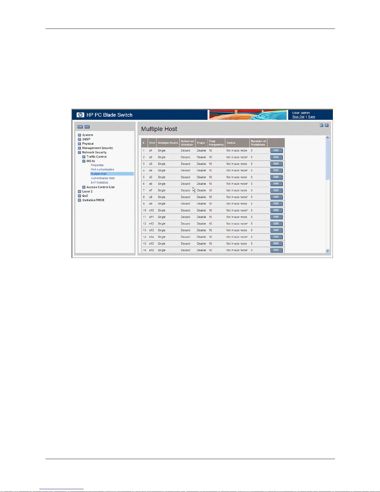
Configuring Multiple Hosts
The Multiple Host page allows network managers to configure advanced port-based
authentication settings for specific ports and VLANs. For more information on advanced
port-based authentication, see Advanced Port-Based Authentication.
To define the network authentication global properties:
1. Click Network Security > 802.1x > Multiple Host. The Multiple Host page opens.
Configuring Device Security
Multiple Host
The Multiple Host page contains the following fields:
❏ Port — Displays the port number for which advanced port-based authentication is
enabled.
❏ Multiple Hosts — Indicates whether multiple hosts are enabled. Multiple hosts must be
enabled in order to either disable the ingress-filter, or to use port-lock security on the
selected port. The possible field values are:
◆ Multiple — Multiple hosts are enabled.
◆ Single — Multiple hosts are disabled.
❏ Action on Violation — Defines the action to be applied to packets arriving in
single-host mode, from a host whose MAC address is not the supplicant MAC address.
The possible field values are:
◆ Forward — Forwards the packet.
◆ Discard — Discards the packets. This is the default value.
◆ Shutdown — Discards the packets and shuts down the port. The port remains shut
down until reactivated, or until the device is reset.
❏ Traps — Indicates if traps are enabled for Multiple Hosts. The possible field values are:
◆ Enable — Indicates that traps are enabled for Multiple hosts.
Embedded Web System User Guide www.hp.com 4-27
Page 54

Configuring Device Security
◆ Disable — Indicates that traps are disabled for Multiple hosts.
❏ Trap Frequency — Defines the time period by which traps are sent to the host. The
Trap Frequency field can be defined only if multiple hosts are disabled. The possible
field range is 1-1000000. The default is 10 seconds.
❏ Status — Indicates the host status. If there is an asterisk (*), the port is either not linked
or is down.
◆ Unauthorized — Indicates that either the port control is Force Unauthorized and the
port link is down, or the port control is Auto but a client has not been authenticated
by the port.
◆ Not in auto mode — Indicates that the port control is Forced Authorized, and
clients have full port access.
◆ Single-host Lock — Indicates that the port control is Auto and a single client has
been authenticated via the port.
◆ No Single Host — Indicates that Multiple Host is enabled.
❏ Number of Violations — Indicates the number of packets that arrived on the interface in
single-host mode, from a host whose MAC address is not the supplicant MAC address.
To modify settings:
The possible field values are:
1. Click Network Security > 802.1x > Multiple Host. The Multiple Host page opens.
2. Click . The Multiple Hosts Settings page opens:
Multiple Hosts Settings
3. Modify the Port, Enable Multiple Hosts, Action on Violation, Enable Traps, and Trap
Frequency fields.
4. Click . The multiple host settings are modified, and the device is updated.
4-28 www.hp.com Embedded Web System User Guide
Page 55

Defining Authentication Hosts
The Authenticated Host page contains a list of authenticated users.
To define authenticated users:
1. Click Network Security > 802.1x > Authenticated Host. The Authenticated Host page
opens:
Configuring Device Security
Authenticated Host
The Authenticated Host page contains the following fields:
❏ User Name — Lists the supplicants that are authenticated and permitted on each port.
❏ Port — Displays the port number.
❏ Session Time — Displays the amount of time (in seconds) that the supplicant was
logged on the port.
❏ Authentication Method — Displays the method by which the last session was
authenticated. The possible field values are:
◆ Remote — 802.1x authentication is not used on this port (port is forced-authorized).
◆ None — The supplicant was not authenticated.
◆ RADIUS — The supplicant was authenticated by a RADIUS server.
❏ MAC Address — Displays the supplicant MAC address.
Embedded Web System User Guide www.hp.com 4-29
Page 56

Configuring Device Security
Viewing EAP Statistics
The EAP Statistics page contains information about EAP packets received on a specific port.
To view the EAP statistics:
1. Click Network Security > 802.1x > EAP Statistics. The EAP Statistics page opens:
EAP Statistics
The EAP Statistics page contains following fields:
❏ Port — Indicates the port, which is polled for statistics.
❏ Refresh Rate — Indicates the amount of time that passes before the EAP statistics are
refreshed. The possible field values are:
◆ 15 Sec — Indicates that the EAP statistics are refreshed every 15 seconds.
◆ 30 Sec — Indicates that the EAP statistics are refreshed every 30 seconds.
◆ 60 Sec— Indicates that the EAP statistics are refreshed every 60 seconds.
◆ No Refresh — Indicates that the EAP statistics are not refreshed.
❏ Frames Receive— Indicates the number of valid EAPOL frames received on the port.
❏ Frames Transmit —Indicates the number of EAPOL frames transmitted via the port.
❏ Start Frames Receive — Indicates the number of EAPOL Start frames received on the
port.
❏ Log off Frames Receive— Indicates the number of EAPOL Logoff frames received on
the port.
❏ Respond ID Frames Receive—Indicates the number of EAP Resp/ID frames received
on the port.
❏ Respond Frames Receive—Indicates the number of valid EAP Response frames
received on the port.
4-30 www.hp.com Embedded Web System User Guide
Page 57

❏ Request ID Frames Transmit—Indicates the number of EAP Req/ID frames
transmitted via the port.
❏ Request Frames Transmit—Indicates the number of EAP Request frames transmitted
via the port.
❏ Invalid Frames Receive—Indicates the number of unrecognized EAPOL frames
received on this port.
❏ Length Error Frames Receive—Indicates the number of EAPOL frames with an
invalid Packet Body Length received on this port.
❏ Last Frame Version—Indicates the protocol version number attached to the most
recently received EAPOL frame.
❏ Last Frame Source—Indicates the source MAC address attached to the most recently
received EAPOL frame.
Configuring Traffic Control
This section contains information for managing both port security and storm control, and
includes the following topics:
■ Defining Access Control Lists
Configuring Device Security
■ Managing Port Security
■ Enabling Storm Control
Defining Access Control Lists
Access Control Lists (ACL) allow network managers to define classification actions and rules for
specific ingress ports. Packets entering an ingress port, with an active ACL, are either admitted or
denied entry and the ingress port is disabled. If they are denied entry, the user can disable the
port.
For example, an ACL rule is defined that states that port number 20 can receive TCP packets,
however, if a UDP packet is received, the packet is dropped. ACLs are composed of Access
Control Entries (ACEs) that are made of the filters that determine traffic classifications. The total
number of ACEs that can be defined in all ACLs together is 1024. The following filters can be
defined as ACEs:
■ Source Port IP Address and Wildcard Mask — Filters the packets by the Source port IP
address and wildcard mask.
■ Destination Port IP Address and Wildcard Mask — Filters the packets by the Destination
port IP address and wildcard mask.
■ AC E Priorit y — Filters the packets by the ACE priority.
■ Protocol — Filters the packets by the IP protocol.
■ DSCP — Filters the packets by the DiffServ Code Point (DSCP) value.
■ IP Precedence — Filters the packets by the IP Precedence.
■ Action — Indicates the action assigned to the packet matching the ACL. Packets are
forwarded or dropped. In addition, the port can be shut down, a trap can be sent to the
network administrator, or the packet is assigned rate limiting restrictions for forwarding.
This section contains the following topics:
■ Defining IP Based Access Control Lists
Embedded Web System User Guide www.hp.com 4-31
Page 58

Configuring Device Security
■ Binding Device Security ACLs
Defining IP Based Access Control Lists
The IP Based ACL page contains information for defining IP Based ACLs, including defining the
ACEs defined for IP Based ACLs.
To define IP Based ACLs:
1. Click Network Security > Access Control List > IP Based ACL. The IP Based ACL page
opens:
IP Based ACL
This image may not contain all possible fields for this page. The complete list is provided in the
✎
following bullets.
The IP Based ACL page contains the following fields:
❏ AC L Name — Displays the user-defined IP based ACLs.
❏ Remove ACL — Removes the ACL configuration.
❏ Rule Priority — Indicates the ACE priority that determines which ACE is matched to a
packet based on a first-match basis. The possible field range is 1-2147483647.
❏ Protocol — Creates an ACE based on a specific protocol.
◆ Select from List — Selects from a protocols list on which ACE can be based.
◆ Protocol ID — Adds user-defined protocols by which packets are matched to the
ACE. Each protocol has a specific protocol number which is unique. The possible
field range is 0-255.
❏ Flag Type — Displays the TCP flag type by which the packets are sorted.
❏ Flag Set — Displays the flag type setting by which the packets are sorted.
❏ ICMP Type — Indicates if filtering the packets by ICMP message type is enabled.
❏ ICMP Code — Indicates the ICMP code by which the packets are filtered.
❏ IGMP Type — Indicates if filtering the packets by IGMP message type is enabled.
4-32 www.hp.com Embedded Web System User Guide
Page 59

Configuring Device Security
❏ Source Port — Defines the TCP/UDP source port to which the ACE is matched. This
field is active only if 800/6-TCP or 800/17-UDP are selected in the Select from List
menu. The possible field range is 0 - 65535.
❏ Destination Port — Defines the TCP/UDP destination port. This field is active only if
800/6-TCP or 800/17-UDP are selected in the Select from List menu. The possible field
range is 0 - 65535.
❏ Source
◆ IP Address — Matches the source port IP address to which packets are addressed to
the ACE.
◆ Mask — Defines the source IP address wildcard mask. Wildcard masks specify
which bits are used and which bits are ignored. A wild card mask of
255.255.255.255 indicates that no bit is important. A wildcard of 0.0.0.0 indicates
that all the bits are important. For example, if the source IP address is
149.36.184.198 and the wildcard mask is 255.36.184.00, the first eight bits of the IP
address are ignored, while the last eight bits are used.
❏ Destination
◆ IP Address — Matches the destination port IP address to which packets are
addressed to the ACE.
◆ Mask — Defines the destination IP address wildcard mask. Select either Match
DSCP or Match IP Precedence:
- Match DSCP — Matches the packet DSCP value to the ACE. Either the DSCP
value or the IP Precedence value is used to match packets to ACLs. The possible
field range is 0-63.
- Match IP Precedence — Matches the packet IP Precedence value to the ACE.
Either the DSCP value or the IP Precedence value is used to match packets to
ACLs. The possible field range is 0-7.
❏ DSCP — Indicates if filtering packets by the DSCP tag values is enabled.
❏ IP-Prec. — Indicates if filtering packets by IP Precedence is enabled.
❏ Action — The ACL forwarding action. Possible values are:
◆ Permit — Forwards packets which meet the ACL criteria.
◆ Deny — Drops packets which meet the ACL criteria.
◆ Shutdown — Drops packets that meet the ACL criteria, and disables the port to
which the packets were addressed. Ports are reactivated from the Interface
Configuration page.
Embedded Web System User Guide www.hp.com 4-33
Page 60

Configuring Device Security
2. Click . The Add IP Based ACL page opens:
Add IP Based ACL
In addition to the fields in the IP Based ACL page, the Add IP Based ACL page contains the
following fields:
❏ New Rule Priority — Defines the new rule priority.
❏ TCP Flags — Filters packets by the TCP flag. Filtered packets are either forwarded or
dropped. Filtering packets by TCP flags increases packet control, which increases
network security. The possible field values are:
◆ Urg — Indicates the packet is urgent. The possible field values are:
- Set — Enables filtering packets by Urg flags.
- Unset — Disables filtering packets by Urg flags.
- Don’t care — Indicates that Urg packets do not influence the packet filtering
process.
◆ Ack — Indicates the packet is acknowledged.
- Set — Enables filtering packets by Ack flags.
- Unset — Disables filtering packets by Ack flags.
- Don’t care — Indicates that Ack packets do not influence the packet filtering
process.
◆ Psh — Indicates the packet is pushed.
- Set — Enables filtering packets by Psh flags.
- Unset — Disables filtering packets by Psh flags.
- Don’t care — Indicates that Psh packets do not influence the packet filtering
process.
4-34 www.hp.com Embedded Web System User Guide
Page 61

Configuring Device Security
◆ Rst — Indicates the connection is dropped.
- Set — Enables filtering packets by Rst flags.
- Unset — Disables filtering packets by Rst flags.
- Don’t care — Indicates that Rst packets do not influence the packet filtering
process.
◆ Syn — Indicates request to start a session.
- Set — Enables filtering packets by Syn flags.
- Unset — Disables filtering packets by Syn flags.
- Don’t care — Indicates that Syn packets do not influence the packet filtering
process.
❏ ICMP — Indicates if ICMP packets are permitted on the network. The possible field
values are:
◆ Select from List — Contains a list of ICMP message types by which the packets can
be filtered.
◆ ICMP Type — Filters packets by ICMP message type. The field values is 0-255.
◆ Any — Filters packets by any ICMP message type.
❏ IGMP — Filters packets by IGMP message or message types.
◆ Select from List — Contains a list of IGMP message types by which the packets can
be filtered.
◆ IGMP Type — Filters packets by IGMP message type. The field range is 0-255.
◆ Any — Filters packets by any IGMP message type.
3. Define the fields.
4. Click .
Embedded Web System User Guide www.hp.com 4-35
Page 62

Configuring Device Security
5. Click . The Add IP Based Rule page opens.
Add IP Based Rule
6. Define the fields.
7. Click . The IP Based ACL is defined, and the device is updated.
To modify an IP-based ACL:
1. Click Network Security > Access Control List > IP Based ACL. The IP Based ACL page
opens.
2. Select an ACL.
4-36 www.hp.com Embedded Web System User Guide
Page 63

3. Click . The Rules Associated with IP-ACL page opens:
Configuring Device Security
Rules Associated with IP-ACL
4. Modify the fields.
5. Click . The IP Based ACL is defined, and the device is updated.
Defining MAC Based Access Control Lists
The MAC Based ACL page allows you to define a MAC-based ACL. ACLs can be added only if
the ACL is not bound to an interface.
To define MAC Based ACLs:
1. Click Network Security > Access Control List > MAC Based ACL.
Embedded Web System User Guide www.hp.com 4-37
Page 64

Configuring Device Security
MAC Based ACL
The MAC Based ACL page contains the following fields:
❏ AC L Name — Displays the user-defined MAC based ACLs.
❏ Priority — Indicates the ACE priority, which determines which ACE is matched to a
packet on a first-match basis. The possible field values are 1-2147483647.
❏ Source MAC Address — Matches the source MAC address to which packets are
addressed to the ACE.
❏ Source Mask — Matches the source MAC address wildcard mask. Wildcards are used
to mask all or part of a source MAC address. Wild card masks specify which bits are
used and which bits are ignored. A wild card mask of FF:FF:FF:FF:FF:FF indicates that
no bit is important. A wildcard of 00.00.00.00.00.00 indicates that all the bits are
important. For example, if the source MAC address E0:3B:4A:C2:CA:E2 and the
wildcard mask is 00:3B:4A:C2:CA:FF, the first two bits of the MAC are used, while the
last two bits are ignored.
❏ Destination MAC Address — Matches the destination MAC address to which packets
are addressed to the ACE.
❏ Destination Mask — Matches the destination MAC address wildcard mask. Wildcards
are used to mask all or part of a destination MAC address.
❏ VLAN ID — Matches the packet’s VLAN ID to the ACE. The possible field values are 1
to 4095.
❏ CoS — Defines the CoS value to which the packet is matched.
❏ CoS Mask —Defines the CoS mask value to which the packet is matched.
❏ Ether Type — Defines the Ether Type to which the packet is matched.
❏ Action — Indicates the ACL forwarding action. Possible field values are:
◆ Permit — Forwards packets which meet the ACL criteria.
◆ Deny — Drops packets which meet the ACL criteria.
4-38 www.hp.com Embedded Web System User Guide
Page 65
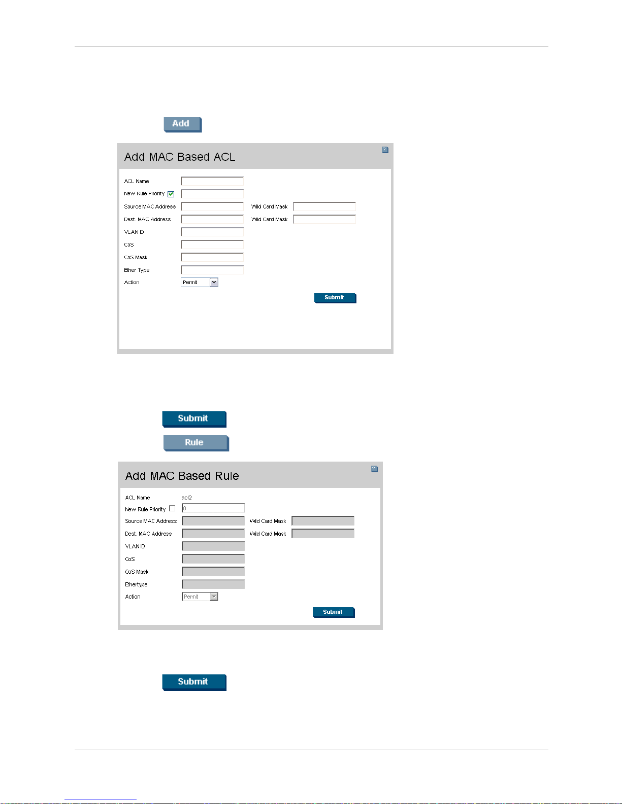
Configuring Device Security
◆ Shutdown — Drops packet that meet the ACL criteria, and disables the port to
which the packet was addressed. Ports are reactivated from the Interface
Configuration Page, see "Chapter 6, in section “Configuring Ports.”.
2. Click . The Add MAC Based ACL page opens:
Add MAC Based ACL
3. Define the ACL Name, New Priority, Protocol, Source MAC Address, Destination MAC
Address, Wild Card Masks, VLAN ID, CoS, CoS Mask, Ether Type, and Action fields.
4. Click . The IP-based protocol is defined, and the device is updated.
5. Click . The Add MAC-Based Rule page opens:
Add MAC-Based Rule
6. Define the fields.
7. Click . The MAC-based ACL is defined, and the device is updated.
To modify a MAC-based ACL:
Embedded Web System User Guide www.hp.com 4-39
Page 66

Configuring Device Security
1. Click Network Security > Access Control List > MAC Based ACL. The MAC Based ACL
page opens.
2. Click . The Edit Rule page opens:
Edit Rule
3. Modify the fields.
4. Click . The MAC based ACL is defined, and the device is updated.
Binding Device Security ACLs
When an ACL is bound to an interface, all the ACE rules that have been defined are applied to
the selected interface.Whenever an ACL is assigned on a port, LAG, or VLAN, flows from that
ingress interface that do not match the ACL are matched to the default rule, which is Drop
unmatched packets.
To bind ACLs to interfaces:
1. Click Network Security > Access Control List > ACL Binding. The ACL Binding page
opens:
4-40 www.hp.com Embedded Web System User Guide
Page 67

ACL Binding
Configuring Device Security
The ACL Binding page contains the following fields:
❏ Copy From Entry Number — Copies the ACL information from the defined interface.
❏ To Entry Number(s) — Copies the ACL information to the defined interface.
❏ Ports — Displays the port security information for ports.
❏ LAGs — Displays the port security information for LAGs.
❏ Interface — Indicates the interface to which the ACL is bound.
❏ AC L Name — Indicates the ACL which is bound to the interface.
2. Select an interface.
3. Click . The Bind ACL page opens:
Bind ACL
4. Define the Interface and Select ACL fields.
5. Click . The ACL is bound the to interface, and the device is updated.
Embedded Web System User Guide www.hp.com 4-41
Page 68

Configuring Device Security
Managing Port Security
Network security can be increased by limiting access on a specific port only to users with
specific MAC addresses. The MAC addresses can be dynamically learned or statically
configured. Locked port security monitors both received and learned packets that are received on
specific ports. Access to the locked port is limited to users with specific MAC addresses. These
addresses are either manually defined on the port, or learned on that port up to the point when it
is locked. When a packet is received on a locked port, and the packet source MAC address is not
tied to that port (either it was learned on a different port, or it is unknown to the system), the
protection mechanism is invoked, and can provide various options. Unauthorized packets
arriving at a locked port are either:
■ Forwarded
■ Discarded with no trap
■ Discarded with a trap
■ Cause the port to be shut down.
Locked port security also enables storing a list of MAC addresses in the configuration file. The
MAC address list can be restored after the device has been reset.
Disabled ports are activated from the Port Security page.
To define port security:
1. Click Network Security > Traffic Control > Port Security. The Port Security page opens:
Port Security
The Port Security page contains the following fields:
❏ Ports — Displays the port security information for ports.
❏ LAGs — Displays the port security information for LAGs.
❏ Interface — Displays the port or LAG name.
❏ Interface Status — Indicates the port security status. The possible field values are:
◆ Unlocked — Indicates the port is currently unlocked. This is the default value.
4-42 www.hp.com Embedded Web System User Guide
Page 69

Configuring Device Security
◆ Locked — Indicates the port is currently locked.
❏ Learning Mode — Defines the locked port type. The Learning Mode field is enabled
only if Locked is selected in the Interface Status field.The possible field values are:
◆ Classic Lock — Locks the port using the classic lock mechanism. The port is
immediately locked, regardless of the number of addresses that have already been
learned.
◆ Limited Dynamic Lock — Locks the port by deleting the current dynamic MAC
addresses associated with the port. The port learns up to the maximum addresses
allowed on the port. Both relearning and aging MAC addresses are enabled.
❏ Max Entries — Specifies the number of MAC addresses that can be learned on the port.
The Max Entries field is enabled only if Locked is selected in the Interface Status
field. In addition, the Limited Dynamic Lock mode is selected. The default is 1.
❏ Action — Indicates the action to be applied to packets arriving on a locked port. The
possible field values are:
◆ Forward — Forwards packets from an unknown source without learning the MAC
address.
◆ Discard — Discards packets from any unlearned source. This is the default value.
◆ Shutdown — Discards packets from any unlearned source and shuts down the port.
The port remains shut down until reactivated, or until the device is reset.
❏ Tr ap — Enables traps when a packet is received on a locked port. The possible field
values are:
◆ Enable — Enables traps.
◆ Disable — Disables traps.
❏ Trap Frequency (Sec) — The amount of time (in seconds) between traps. The default
value is 10 seconds.
2. Click . The Interface Table Settings page opens:
Interface Table Settings
3. Modify the Interface, Lock Interface, Action on Violation, Enable Trap, and Trap
Frequency fields.
Embedded Web System User Guide www.hp.com 4-43
Page 70

Configuring Device Security
4. Click . The port security settings are defined, and the device is updated.
Enabling Storm Control
Storm control limits the amount of Multicast and Broadcast frames accepted and forwarded by
the device. When Layer 2 frames are forwarded, Broadcast and Multicast frames are flooded to
all ports on the relevant VLAN. This occupies bandwidth, and loads all nodes on all ports.
A Broadcast Storm is a result of an excessive amount of broadcast messages simultaneously
transmitted across a network by a single port. Forwarded message responses are heaped onto the
network, straining network resources or causing the network to time out.
Storm control is enabled for all Gigabit ports by defining the packet type and the rate by which
the packets are transmitted. The system measures the incoming Broadcast and Multicast frame
rates separately on each port, and discards the frames when the rate exceeds a user-defined rate.
The Storm Control page provides fields for configuring broadcast storm control.
To enable storm control:
1. Click Network Security > Traffic Control > Storm Control. The Storm Control page
opens:
Storm Control
The Storm Control page contains the following fields:
❏ Copy From Entry Number — Copies the storm control parameters from the selected
interface.
❏ To Entry Number(s) — Copies the storm control parameters to the defined interface.
❏ Port — Indicates the port on which storm control is enabled.
❏ Enable Broadcast Control — Indicates if forwarding Broadcast packet types on the
interface is enabled.
4-44 www.hp.com Embedded Web System User Guide
Page 71

Configuring Device Security
❏ Broadcast Rate Threshold — Indicates the maximum rate (kilobits per second) at
which unknown packets are forwarded. The range is 70-100,000. The default value is
3500.
❏ Broadcast Mode — Specifies the Broadcast mode currently enabled on the device. The
possible field values are:
◆ Unknown Unicast, Multicast & Broadcast — Counts Unicast, Multicast, and
Broadcast traffic.
◆ Multicast & Broadcast — Counts Broadcast and Multicast traffic.
◆ Broadcast Only — Counts only Broadcast traffic.
2. Click . The Storm Control Settings page opens:
Storm Control Settings
3. Modify the Port, Enable Broadcast Control, Broadcast Mode, and Broadcast Rate
Threshold fields.
4. Click . Storm control is enabled on the device.
Embedded Web System User Guide www.hp.com 4-45
Page 72

Configuring Device Security
4-46 www.hp.com Embedded Web System User Guide
Page 73

5
Configuring System Logs
This section provides information for managing system logs. System logs enable viewing device
events in real time and recording the events for later usage. System Logs record and manage
events, and report errors and informational messages.
Event messages have a unique format, which is the Syslog protocols recommended message
format for all error reporting. For example, Syslog and local device reporting messages are
assigned a severity code and include a message mnemonic which identifies the source
application generating the message. This allows messages to be filtered based on their urgency or
relevancy. The message severity determines the set of event logging devices that are sent for each
event message.
The following table lists the log severity levels:
System Log Severity Levels
Severity Level Message
Emergency 0 (Highest) The system is not functioning.
Alert 1 The system needs immediate attention.
Critical 2 The system is in a critical state.
Error 3 A system error has occurred.
Warning 4 A system warning has occurred.
Notice 5 The system is functioning properly, but a system
notice has occurred.
Informational 6 Provides device information.
Debug 7 Provides detailed information about the log. If a
Debug error occurs, contact Customer Tech
Support.
This section includes the following topics:
■ Defining General Log Properties
■ Viewing Memory Logs
■ Viewing Flash Logs
■ Defining System Log Servers
Embedded Web System User Guide www.hp.com 5-1
Page 74

Configuring System Logs
Defining General Log Properties
The Logs Properties page contains fields for defining which events are recorded to which logs. It
contains fields for enabling logs globally and parameters for defining logs. Log messages are
listed from highest to lowest severity.
To define system log parameters:
1. Click System > Logs > Properties. The Logs Properties page opens:
Logs Properties
The Logs Properties page contains the following fields:
❏ Enable Logging — Indicates if device global logs for Cache, File, and Server Logs are
enabled. Console logs are enabled by default. The possible field values are:
◆ Checked — Enables device logs.
◆ Unchecked — Disables device logs.
❏ Severity — The following are the available log severity levels:
◆ Emergency — The highest warning level. If the device is down or not functioning
properly, an emergency log message is saved to the specified logging location.
◆ Alert — The second highest warning level. An alert log is saved if there is a serious
device malfunction. For example, all device features are down.
◆ Critical — The third highest warning level. A critical log is saved if a critical device
malfunction occurs. For example, two device ports are not functioning, while the rest
of the device ports remain functional.
◆ Error — A device error has occurred. For example, a single port is offline.
◆ Warning — The lowest level of a device warning. The device is functioning, but an
operational problem has occurred.
◆ Notice — The system is functioning properly, but a system notice has occurred.
◆ Informational — Provides device information.
◆ Debug — Provides detailed information about the log. If a Debug error occurs,
contact Customer Tech Support.
5-2 www.hp.com Embedded Web System User Guide
Page 75

When a severity level is selected, all severity level choices above the selection are selected
✎
automatically.
❏ Console — Defines the minimum severity level from which logs are sent to the console.
❏ Memory Logs — Defines the minimum severity level from which logs are sent to the
log file stored in RAM (Cache).
❏ Log Flash — Defines the minimum severity level from which logs are sent to the log file
stored in FLASH memory.
2. Define the Enable Logging and Severity fields.
3. Click . The system log parameters are set, and the device is updated.
Viewing Memory Logs
The Memory page contains all system logs that are saved in RAM (Cache) in chronological
order.
To view system logs:
» Click System > Logs > Memory. The Memory page opens:
Configuring System Logs
Memory
The Memory page contains the following fields:
■ Log Index — Displays the log number.
■ Log Time — Displays the time at which the log was generated.
■ Severity — Displays the log severity.
■ Description — Displays the log message text.
Embedded Web System User Guide www.hp.com 5-3
Page 76

Configuring System Logs
Viewing Flash Logs
The Flash page contains information about log entries saved to the log file in Flash memory,
including the time the log was generated, the log severity, and a description of the log message.
The Flash logs are available after reboot.
To view the Flash logs:
» Click System > Logs > Flash. The Flash page opens:
Flash
The Flash page contains the following fields:
■ Log Index — Displays the log number.
■ Log Time — Displays the time at which the log was generated.
■ Severity — Displays the log severity.
■ Description — Displays the log message text.
5-4 www.hp.com Embedded Web System User Guide
Page 77

Defining System Log Servers
The Servers page contains information for viewing and configuring the remote log servers. New
log servers can be defined, and the log severity can be sent to each server.
To define a system log server:
1. Click System > Logs > Servers. The Servers page opens:
Configuring System Logs
Servers
The Servers page contains the following fields:
❏ Server — Specifies the server to which logs can be sent.
❏ UDP Port — Defines the UDP port to which the server logs are sent. The possible range
is 1 - 65535. The default value is 514.
❏ Facility — Defines an application from which system logs are sent to the remote server.
Only one facility can be assigned to a single server. If a second facility level is assigned,
the first facility is overridden. All applications defined for a device utilize the same
facility on a server. The field default is Local7. The possible field values are Local0 Local7.
❏ Description — A user-defined server description.
❏ Minimum Severity — Indicates the minimum severity from which logs are sent to the
server. For example, if Notice is selected, all logs with a severity level of Notice and
higher are sent to the remote server.
Embedded Web System User Guide www.hp.com 5-5
Page 78

Configuring System Logs
2. Click . The Add Syslog Server page opens:
Add Syslog Server
3. Define the Log Server IP Address, UDP Port, Facility, Description, and Minimum
Severity fields.
4. Click . The system log server is defined, and the device is updated.
5-6 www.hp.com Embedded Web System User Guide
Page 79

This section provides information for configuring ports, LAGs, and LACP, and includes the
following topics:
■ Configuring Ports
■ Aggregating Ports
■ Configuring VLANs
Configuring Ports
The Port Configuration page contains fields for defining port parameters.
To define port parameters:
1. Click Layer 2 > Interface > Port Configuration. The Port Configuration page opens:
6
Configuring Interfaces
Port Configuration
The Port Configuration page contains the following fields:
❏ Copy From Entry Number — Copies the port configuration parameters from the
selected interface.
❏ To Entry Number(s) — Copies the port configuration parameters to the defined
interface.
❏ Interface — Displays the port number.
❏ Description — Displays the user-defined description.
Embedded Web System User Guide www.hp.com 6-1
Page 80

Configuring Interfaces
❏ Port Type — Displays the port type. The possible field values are:
❏ Port Status — Indicates whether the port is currently operational or non-operational.
❏ Port Speed — Displays the configured rate for the port. The port type determines what
❏ Duplex Mode — Displays the port duplex mode. This field is configurable only when
◆ 1000M-copper — Indicates the port has a copper port connection and is operating at
1000 Mbps.
◆ 1000M-fiber — Indicates the port has a fiber optic port connection.
The possible field values are:
◆ Up — Indicates the port is currently operating.
◆ Down — Indicates the port is currently not operating.
speed setting options are available. Port speed can only be configured when auto
negotiation is disabled. The possible field values are:
◆ 10M — Indicates the port is currently operating at 10 Mbps.
◆ 100M — Indicates the port is currently operating at 100 Mbps.
◆ 1000M — Indicates the port is currently operating at 1000 Mbps.
auto negotiation is disabled, and the port speed is set to 10M or 100M. This field cannot
be configured on LAGs. The possible field values are:
◆ Full — The interface supports transmission between the device and its link partner
in both directions simultaneously.
◆ Half — The interface supports transmission between the device and the link partner
in one direction at a time.
❏ Auto Negotiation — Displays the auto negotiation status on the port. Auto negotiation is
a protocol between two link partners that enables a port to advertise its transmission rate,
duplex mode, and flow control abilities to its link partner.
❏ Advertisement — Defines the auto negotiation setting the port advertises. The possible
field values are:
◆ Max Capability — Indicates that all port speeds and duplex mode settings are
accepted.
◆ 10H — Indicates that the port advertises for a 10 Mbps speed port and half duplex
mode setting.
◆ 10F — Indicates that the port advertises for a 10 Mbps speed port and full duplex
mode setting.
◆ 100H — Indicates that the port advertises for a 100 Mbps speed port and half duplex
mode setting.
◆ 100F — Indicates that the port advertises for a 100 Mbps speed port and full duplex
mode setting.
◆ 1000H — Indicates that the port advertises for a 1000 Mbps speed port and half
duplex mode setting.
◆ 1000F — Indicates that the port advertises for a 1000 Mbps speed port and full
duplex mode setting.
❏ Back Pressure — Displays the back pressure mode on the port. Back pressure mode is
used with half duplex mode to disable ports from receiving messages.
6-2 www.hp.com Embedded Web System User Guide
Page 81

Configuring Interfaces
❏ Flow Control — Displays the flow control status on the port. Operates when the port is
in full duplex mode.
❏ MDI/MDIX — Displays the MDI/MDIX status on the port. Hubs and switches are
deliberately wired opposite from the way that end stations are wired, so that when a hub
or switch is connected to an end station, a straight through Ethernet cable can be used,
and the pairs are matched up properly. When two hubs or switches are connected to each
other, or two end stations are connected to each other, a crossover cable is used to ensure
that the correct pairs are connected.
The possible field values are:
◆ Auto — Used to automatically detect the cable type.
◆ MDI (Media Dependent Interface) — Used for end stations.
◆ MDIX (Media Dependent Interface with Crossover) — Used for hubs and
switches.
❏ LAG — Indicates whether the port is part of a Link Aggregation Group (LAG).
2. Click
. The Port Configuration Settings page opens:
Port Configuration Settings
In addition to the fields in the Port Configuration page, the Port Configuration Settings page
includes the following field:
❏ Reactivate Suspended Port — Indicates whether the port is suspended or activated.
3. Check the Reactivate Suspended Port field to reactivate a suspended port.
Embedded Web System User Guide www.hp.com 6-3
Page 82

Configuring Interfaces
4. Modify the fields.
5. Click . The port parameters are saved.
Aggregating Ports
Link Aggregation optimizes port usage by linking a group of ports together to form a single
LAG. Aggregating ports multiplies the bandwidth between the devices, increases port flexibility,
and provides link redundancy.
The device supports both static LAGs and Link Aggregation Control Protocol (LACP) LAGs.
LACP LAGs negotiate aggregating port links with other LACP ports located on a different
device. If the other device ports are also LACP ports, the devices establish a LAG between them.
Ensure the following:
■ All ports within a LAG must be the same media type.
■ A VLAN is not configured on the port.
■ The port is not assigned to a different LAG.
■ Auto negotiation mode is not configured on the port.
■ The port is in full duplex mode.
■ All ports in the LAG have the same ingress filtering and tagged modes.
■ All ports in the LAG have the same back pressure and flow control modes.
■ All ports in the LAG have the same priority.
■ All ports in the LAG have the same transceiver type.
■ The device supports up to eight LAGs and eight ports in each LAG.
■ Ports can be configured as LACP ports, only if the ports are not part of a previously
configured LAG.
■ Ports added to a LAG lose their individual port configuration. When ports are removed from
the LAG, the original port configuration is applied to the ports.
This section contains the following topics:
■ Configuring LAG Parameters
■ Configuring LAG Membership
■ Configuring LACP Parameters
6-4 www.hp.com Embedded Web System User Guide
Page 83

Configuring LAG Parameters
The LAG Configuration page contains fields for configuring parameters for LAGs. The device
supports up to eight ports per LAG and eight LAGs per system.
To define LAG parameters:
Configuring Interfaces
1. Click Layer 2 > Interface > LAG Configuration. The
LAG Configuration
The LAG Configuration page contains the following fields:
LAG Configuration page opens:
❏ Copy From Entry Number — Copies the LAG configuration parameters from the
selected interface.
❏ To Entry Number(s) — Copies the LAG configuration parameters to the defined
interface.
❏ LAG — Displays the LAG number.
❏ Description — Displays the user-defined LAG name and/or description.
❏ Ty pe — Indicates the type of LAG defined by the first port assigned to the LAG. For
example, 100-Copper, or 100-Fiber.
❏ Status — Indicates if the LAG is currently linked. The possible field values are;
◆ Up — Indicates the LAG is currently linked, and is forwarding or receiving traffic.
◆ Down — Indicates the LAG is not currently linked, and is not forwarding or
receiving traffic.
❏ Speed — Displays the configured aggregated rate for the LAG. The possible field values
are:
◆ 10 — Indicates the port is currently operating at 10 Mbps.
◆ 100 — Indicates the port is currently operating at 100 Mbps.
◆ 1000 — Indicates the port is currently operating at 1000 Mbps.
Embedded Web System User Guide www.hp.com 6-5
Page 84

Configuring Interfaces
❏ Auto Negotiation — Displays the auto negotiation status of the LAG. Auto negotiation
❏ Flow Control — Displays the flow control status of the LAG.
2. Click . The LAG Configuration Settings page opens:
is a protocol between two link partners that enables a port to advertise its transmission
rate, duplex mode, and flow control abilities to its partner.
LAG Configuration Settings
3. Define the LAG and LAG Configuration fields.
4. Click . The LAG configuration settings are saved.
6-6 www.hp.com Embedded Web System User Guide
Page 85

Configuring LAG Membership
The LAG Membership page contains fields for defining membership for LAGs.
To define LAG membership:
1. Click Layer 2 > Interface > LAG Membership. The LAG Membership page opens:
Configuring Interfaces
LAG Membership
The LAG Membership page contains the following fields:
❏ LAG — Displays the port which is attached to the LAG.
❏ Name — Displays the user-defined port name.
❏ Link State — Indicates if the LAG is currently linked. The possible field values are;
◆ Up — Indicates the LAG is currently linked and is forwarding or receiving traffic.
◆ Down — Indicates the LAG is not currently linked and is not forwarding or
receiving traffic.
❏ Member — Indicates if the port is currently attached to the LAG.
Embedded Web System User Guide www.hp.com 6-7
Page 86

Configuring Interfaces
2. Click . The LAG Membership Settings page opens:
LAG Membership Settings
3. Define the fields.
4. Click . The LAG membership is defined, and the device is updated.
6-8 www.hp.com Embedded Web System User Guide
Page 87

Configuring LACP Parameters
LAG ports can contain different media types if the ports are operating at the same speed.
Aggregated links can be set up manually or can be automatically established by enabling LACP
on the relevant links. Aggregate ports can be linked into link-aggregation port groups. Each
group is comprised of ports with the same speed. The LACP Parameters page contains fields for
configuring LACP for LAGs.
To configure LACP for LAGs:
1. Click Layer 2 > Interface > LACP Parameters. The LACP Parameters page opens:
Configuring Interfaces
LACP Parameters
The LACP Parameters page contains the following fields:
❏ LACP System Priority — Specifies system priority value. The field range is 1-65535.
The field default is 1.
❏ Port — Displays the port number to which timeout and priority values are assigned.
❏ Port-Priority — Displays the LACP priority value for the port. The field range is
1-65535.
❏ LACP Timeout — Displays the administrative LACP timeout.
Embedded Web System User Guide www.hp.com 6-9
Page 88

Configuring Interfaces
2. Click . The LACP Parameters Settings page opens:
LACP Parameters Settings
3. Edit the LACP Port Priority and LACP Timeout fields.
4. Click . The LACP settings are saved, and the device is updated.
Configuring VLANs
VLANs are logical subgroups with a Local Area Network (LAN), which combine user stations
and network devices into a single unit, regardless of the physical LAN segment to which they are
attached. VLANs allow network traffic to flow more efficiently within subgroups. VLANs use
software to reduce the amount of time it takes for network changes, additions, and moves to be
implemented.
VLANs have no minimum number of ports and can be created per unit, per device, or through
any other logical connection combination, since they are software-based and are not defined by
physical attributes.
VLANs function at Layer 2. Since VLANs isolate traffic within the VLAN, a Layer 3 router
working at a protocol level is required to allow traffic flow between VLANs. Layer 3 routers
identify segments and coordinate with VLANs. VLANs are Broadcast and Multicast domains.
Broadcast and Multicast traffic is transmitted only in the VLAN in which the traffic is generated.
VLAN tagging provides a method of transferring VLAN information between VLAN groups.
VLAN tagging attaches a 4-byte tag to packet headers. The VLAN tag indicates to which VLAN
the packets belong. VLAN tags are attached to the VLAN by the end station or the network
device. VLAN tags also contain VLAN network priority information.
Combining VLANs and GARP (Generic Attribute Registration Protocol) allows network
managers to define network nodes into Broadcast domains.
This section contains the following topics:
■ Defining VLAN Properties
■ Defining VLAN Membership
■ Defining VLAN Interface Settings
■ Configuring GARP
6-10 www.hp.com Embedded Web System User Guide
Page 89

Defining VLAN Properties
The VLAN Properties page provides information and global parameters for configuring and
working with VLANs.
To define VLAN properties:
1. Click Layer 2 > VLAN > Properties. The VLAN Properties page opens:
Configuring Interfaces
VLAN Properties
The VLAN Properties page contains the following fields:
❏ VLAN ID — Displays the VLAN ID.
❏ VLAN Name — Displays the user-defined VLAN name.
❏ Ty pe — Displays the VLAN type. The possible field values are:
◆ Dynamic — Indicates the VLAN was dynamically created through GARP.
◆ Static — Indicates the VLAN is user-defined.
◆ Default — Indicates the VLAN is the default VLAN. The default VLAN is 4094.
❏ Authentication — Indicates whether unauthorized users can access a Guest VLAN. The
possible field values are:
◆ Enabled — Enables unauthorized users to use the Guest VLAN.
◆ Disabled — Disables unauthorized users from using the Guest VLAN.
Embedded Web System User Guide www.hp.com 6-11
Page 90

Configuring Interfaces
2. Click . The Add VLAN page opens:
Add VLAN
3. Define the VLAN ID and VLAN Name fields.
4. Click . The VLAN properties are defined, and the device is updated.
When the Spanning Tree VLAN Separation option is enabled, the switch only
✎
retransmits BPDUs on the VLAN they were received from. Initial BPDUs only
transmit on the VLAN the port is assigned to. For more information, see Chapter 9,
“Configuring Spanning Tree.”
6-12 www.hp.com Embedded Web System User Guide
Page 91

Defining VLAN Membership
The VLAN Membership page contains a table that maps VLAN parameters to ports. Ports are
assigned VLAN membership by toggling through the Port Control settings.
To define VLAN membership:
1. Click Layer 2 > VLAN > Membership. The VLAN Membership page opens:
Configuring Interfaces
VLAN Membership
The VLAN Membership page contains the following fields:
❏ VLAN ID — Displays the user-defined VLAN ID.
❏ VLAN Name — Displays the name of the VLAN.
❏ VLAN Type — Indicates the VLAN type. The possible field values are:
◆ Dynamic — Indicates the VLAN was dynamically created through GARP.
◆ Static — Indicates the VLAN is user-defined.
◆ Default — Indicates the VLAN is the default VLAN.
❏ Ports — Indicates the port membership.
❏ LAG — Indicates the LAG membership.
❏ Untagged (Brown) — Indicates the interface is an untagged VLAN member. Packets
forwarded by the interface are untagged.
❏ Tagged (Red) — Indicates the interface is a tagged VLAN member. All packets
forwarded by the interface are tagged. The packets contain VLAN information.
❏ Exclude (Gray) — Excludes the interface from the VLAN. However, the interface can
be added to the VLAN through GARP.
Embedded Web System User Guide www.hp.com 6-13
Page 92

Configuring Interfaces
❏ Forbidden (Purple) — Denies the interface VLAN membership, even if GARP
indicates the port is to be added.
2. Select a VLAN in the VLAN ID field. The VLAN membership settings are displayed.
3. Define the fields.
4. Click . The VLAN membership settings are defined, and the device is
updated.
Defining VLAN Interface Settings
The VLAN Interface Settings page contains fields for managing ports that are part of a VLAN.
The Port Default VLAN ID (PVID) is configured on the VLAN Interface Settings page. All
untagged packets arriving at the device are tagged with the PVID.
To define VLAN interfaces:
1. Click Layer 2 > VLAN > Interface Settings. The VLAN Interface Settings page opens:
VLAN Interface Settings
The VLAN Interface Settings page contains the following fields:
❏ Ports — Displays VLAN interface settings for ports.
❏ LAGs — Displays the VLAN interface settings or LAGs.
❏ Interface — Displays the port number included in the VLAN.
❏ Interface VLAN Mode — Displays the port mode. The possible values are:
◆ General — Indicates the port belongs to VLANs, and each VLAN is user-defined as
tagged or untagged (full IEEE802.1q mode).
◆ Access — Indicates the port belongs to a single untagged VLAN. When a port is in
Access mode, the packet types which are accepted on the port cannot be designated.
Ingress filtering cannot be enabled or disabled on an access port.
6-14 www.hp.com Embedded Web System User Guide
Page 93

Configuring Interfaces
◆ Tru nk — Indicates the port belongs to VLANs in which all ports are tagged, except
for one port that can be untagged.
❏ PVID — Assigns a VLAN ID to untagged packets. The possible values are 1-4094.
VLAN 4095 is defined as per standard industry practice as the Discard VLAN. Packets
classified as Discard VLAN are dropped.
❏ Frame Type — Specifies the packet type accepted on the port. The possible field values
are:
◆ Admit Tag Only — Only tagged packets are accepted on the port.
◆ Admit All — Both tagged and untagged packets are accepted on the port.
❏ Ingress Filtering — Indicates whether ingress filtering is enabled on the port. The
possible field values are:
◆ Enable — Enables ingress filtering on the device. Ingress filtering discards packets
that are defined to VLANs of which the specific port is not a member.
◆ Disable — Disables ingress filtering on the device.
❏ Reserved VLAN — Indicates the VLAN selected by the user to be the reserved VLAN
if not in use by the system.
2. Click . The VLAN Interface Settings page opens:
VLAN Interface Settings
3. Define the Port Interface, Port VLAN Mode, PVID, Frame Type, Ingress Filtering, and
Reserve VLAN for Internal Use fields.
4. Click . The VLAN interface settings are modified, and the device is updated.
Embedded Web System User Guide www.hp.com 6-15
Page 94

Configuring Interfaces
Configuring GARP
This section contains information for configuring Generic Attribute Registration Protocol
(GARP). This section includes the following topics:
■ Defining GARP
■ Defining GVRP
■ Viewing GVRP Statistics
Defining GARP
GARP is a general-purpose protocol that registers any network connectivity or membership-style
information. GARP defines a set of devices interested in a given network attribute, such as
VLAN or multicast address. When configuring GARP, ensure the following:
■ The leave timer must be greater than or equal to three times the join time.
■ The leave all timer must be greater than the leave timer.
■ Set the same GARP timer values on all Layer 2 connected devices. If the GARP timers are
set differently on the Layer 2 connected devices, the GARP application does not operate
successfully.
To define GARP on the device:
1. Click Layer 2 > VLAN > GARP Settings. The GARP Settings page opens:
GARP Settings
The GARP Settings page contains the following fields:
❏ Ports — Displays the port settings for GARP.
❏ LAGs — Displays the LAG settings for GARP.
❏ Interface — Displays the port or LAG on which GARP is enabled.
6-16 www.hp.com Embedded Web System User Guide
Page 95

Configuring Interfaces
❏ Join Timer — Indicates the amount of time, in centiseconds, that PDUs are transmitted.
The default value is 20 centiseconds.
❏ Leave Timer — Indicates the amount of time lapse, in centiseconds, that the device
waits before leaving its GARP state. Leave time is activated by a Leave All Timer
message sent/received, and is cancelled by a Join message received. Leave Timer must
be greater than or equal to three times the Join Timer. The default value is 60
centiseconds.
❏ Leave All Timer — Indicates the amount of time lapse, in centiseconds, that all devices
wait before leaving the GARP state. The Leave All Timer must be greater than the Leave
Timer. The default value is 1000 centiseconds.
2. Click . The GARP Parameter Settings page opens:
GARP Parameter Settings
3. Modify the Interface, Join Timer (centiseconds), Leave Timer (centiseconds), and Leave
All Timer (centiseconds) fields.
4. Click . The GARP parameters are defined, and the device is updated.
Embedded Web System User Guide www.hp.com 6-17
Page 96

Configuring Interfaces
Defining GVRP
GARP VLAN Registration Protocol (GVRP) is specifically provided for automatic distribution of
VLAN membership information among VLAN-aware bridges. GVRP allows VLAN-aware
bridges to automatically learn VLANs to bridge ports mapping, without having to individually
configure each bridge and register VLAN membership.
To define GVRP on the device:
1. Click Layer 2 > VLAN > GVRP Parameters. The GVRP Parameters page opens:
GVRP Parameters
The GVRP Parameters page contains the following fields:
❏ GVRP Global Status — Indicates if GVRP is enabled on the device. The possible field
values are:
◆ Enable — Enables GVRP on the selected device.
◆ Disable — Disables GVRP on the selected device.
❏ Port — Displays the GVRP parameters for ports.
❏ LAG — Displays the GVRP parameters for LAGs.
❏ Interface — Displays the port on which GVRP is enabled. The possible field values are:
◆ Port — Indicates the port number on which GVRP is enabled.
◆ LAG — Indicates the LAG number on which GVRP is enabled.
❏ GVRP State — Indicates if GVRP is enabled on the port. The possible field values are:
◆ Enabled — Enables GVRP on the selected port.
◆ Disabled — Disables GVRP on the selected port.
6-18 www.hp.com Embedded Web System User Guide
Page 97

Configuring Interfaces
❏ Dynamic VLAN Creation — Indicates if Dynamic VLAN creation is enabled on the
interface. The possible field values are:
◆ Enabled — Enables Dynamic VLAN creation on the interface.
◆ Disabled — Disables Dynamic VLAN creation on the interface.
❏ GVRP Registration — Indicates if VLAN registration through GVRP is enabled on the
device. The possible field values are:
◆ Enabled — Enables GVRP registration on the device.
◆ Disabled — Disables GVRP registration on the device.
2. Define the GVRP Global Status field.
3. Click .
To modify GVRP parameters:
1. Click Layer 2 > VLAN > GVRP Parameters. The GVRP Parameters page opens.
2. Click . The GVRP Parameters Settings page opens:
GVRP Parameters Settings
3. Modify the GVRP State, Dynamic VLAN Creation, and GVRP Registration fields.
4. Click . The GVRP Interface parameters are sent, and the device is updated.
Embedded Web System User Guide www.hp.com 6-19
Page 98

Configuring Interfaces
Viewing GVRP Statistics
The GVRP Statistics page contains device statistics for GVRP.
To view GVRP statistics:
» Click Layer 2 > VLAN > GVRP Statistics. The GVRP Statistics page opens:
GVRP Statistics
The GVRP Statistics page contains the following fields:
❏ Interface — Specifies the interface type for which the statistics are displayed.
◆ Port — Indicates port statistics are displayed.
◆ LAG — Indicates LAG statistics are displayed.
❏ Refresh Rate — Indicates the amount of time that passes before the GVRP statistics are
refreshed. The possible field values are:
◆ 15 Sec — Indicates that the GVRP statistics are refreshed every 15 seconds.
◆ 30 Sec — Indicates that the GVRP statistics are refreshed every 30 seconds.
◆ 60 Sec — Indicates that the GVRP statistics are refreshed every 60 seconds.
◆ No Refresh — Indicates that the GVRP statistics are not refreshed.
❏ Join Empty — Displays the device GVRP Join Empty statistics.
❏ Empty — Displays the device GVRP Empty statistics.
❏ Leave Empty — Displays the device GVRP Leave Empty statistics.
❏ Join In — Displays the device GVRP Join In statistics.
❏ Leave In — Displays the device GVRP Leave In statistics.
❏ Leave All — Displays the device GVRP Leave All statistics.
6-20 www.hp.com Embedded Web System User Guide
Page 99

Configuring Interfaces
❏ Invalid Protocol ID — Displays the device GVRP Invalid Protocol ID statistics.
❏ Invalid Attribute Type — Displays the device GVRP Invalid Attribute ID statistics.
❏ Invalid Attribute Value — Displays the device GVRP Invalid Attribute Value statistics.
❏ Invalid Attribute Length — Displays the device GVRP Invalid Attribute Length
statistics.
❏ Invalid Event — Displays the device GVRP Invalid Event statistics.
Embedded Web System User Guide www.hp.com 6-21
Page 100

Configuring Interfaces
6-22 www.hp.com Embedded Web System User Guide
 Loading...