

Page 1

a Hewlett Packard
Enterprise company
Aruba 8320 Switch
Installation and Getting Started Guide
Part Number: 5200-3553
Published: December, 2017
Edition: 1
Page 2

© 2017 Hewlett Packard Enterprise Development LP
Notices
The information contained herein is subject to change without notice. The only warranties for Hewlett Packard
Enterprise products and services are set forth in the express warranty statements accompanying such products
and services. Nothing herein should be construed as constituting an additional warranty. Hewlett Packard
Enterprise shall not be liable for technical or editorial errors or omissions contained herein.
Confidential computer software. Valid license from Hewlett Packard Enterprise required for possession, use, or
copying. Consistent with FAR 12.211 and 12.212, Commercial Computer Software, Computer Software
Documentation, and Technical Data for Commercial Items are licensed to the U.S. Government under vendor's
standard commercial license.
Links to third-party websites take you outside the Hewlett Packard Enterprise website. Hewlett Packard Enterprise
has no control over and is not responsible for information outside the Hewlett Packard Enterprise website.
Applicable products
Aruba 8320 48p 10G SFP/SFP+ and 6p 40G QSFP+ with X472 5 Fans 2 Power
Supply Switch Bundle
Related publications
• Aruba 8320 Switch Quick Setup Guide and Safety/Regulatory Information
• ArubaOS-Switch and ArubaOS-CX Transceiver Guide
To view and download the above publications, visit the Hewlett Packard Enterprise Information Library at
http://www.hpe.com/networking/ResourceCenter
.
JL479A
Page 3

Contents
Chapter 1 Introducing the Aruba 8320 Switch ................................................. 5
Front of the switch ...................................................................................................................................... 6
Back of the switch ..................................................................................................................................... 12
Switch features ......................................................................................................................................... 14
Chapter 2 Installing the switch ........................................................................ 15
Included parts ........................................................................................................................................... 15
Installation procedures ............................................................................................................................. 16
Installation precautions ............................................................................................................................. 17
1. Prepare the installation site .................................................................................................................. 18
2. Mount the switch ................................................................................................................................... 18
3. Install transceivers ................................................................................................................................ 21
4. Connect the switch to a power source .................................................................................................. 23
5. Connect a management console .......................................................................................................... 23
6. Connect the network cables ................................................................................................................. 25
Chapter 3 Getting started with switch configuration .................................... 27
Recommended minimal configuration ...................................................................................................... 27
Chapter 4 Replacing components................................................................... 30
Replacing a power supply ........................................................................................................................ 30
Replacing a fan tray .................................................................................................................................. 31
Chapter 5 Troubleshooting .............................................................................. 32
Basic troubleshooting tips ......................................................................................................................... 32
Diagnosing with the LEDs ........................................................................................................................ 33
Hardware diagnostic tests ........................................................................................................................ 36
Restoring the factory default configuration ............................................................................................... 37
Downloading new switch software ............................................................................................................ 37
Hewlett Packard Enterprise Customer Support Services ......................................................................... 37
Chapter 6 Specifications .................................................................................. 38
Switch specifications ................................................................................................................................ 38
Standards ................................................................................................................................................. 40
Chapter 7 Cabling and technology information............................................. 41
Cabling specifications ............................................................................................................................... 41
Technology distance specifications .......................................................................................................... 42
Mode conditioning patch cord ................................................................................................................... 43
Chapter 8 Support and other resources ......................................................... 45
Accessing Hewlett Packard Enterprise support ........................................................................................ 45
Before calling support ............................................................................................................................... 45
Accessing updates ................................................................................................................................... 46
3
Page 4

Websites ................................................................................................................................................... 46
Customer self repair ................................................................................................................................. 47
Remote support ........................................................................................................................................ 47
Documentation feedback .......................................................................................................................... 47
4 Aruba 8320 Switch Installation and Getting Started Guide
Page 5

Chapter 1
Introducing the Aruba 8320 Switch
The Aruba 8320 switch is a multiport switch that can be used to build high-performance switched networks. The
switch is a store-and-forward device offering low latency for high-speed networking. The Aruba 8320 switch also
supports full network management capabilities.
This switch is described in this manual:
Switch
Aruba 8320 48p 10G SFP/SFP+ and 6p 40G QSFP+ with X472 5 Fans 2 Power Supply Switch Bundle (JL479A)
Accessories list:
Accessory
Power supply Aruba X371 400W 100-240VAC Power Supply (JL480A)
Fan tray Aruba X721 Front-to-Back Fan (JL481A)
Rack kit Aruba X472 2-Post Rack Kit (JL482A)
This chapter describes this switch with the following information:
• Front of the switch:
◦ Network ports
◦ Console port
◦ Out-of-band management (OOBM)
◦ LEDs
◦ Reset button
• Back of the switch:
◦ Power supplies and connectors
◦ Fan modules
• Switch features
◦ Hardware features
◦ Software features
◦ Management software
Chapter 1 Introducing the Aruba 8320 Switch 5
Page 6
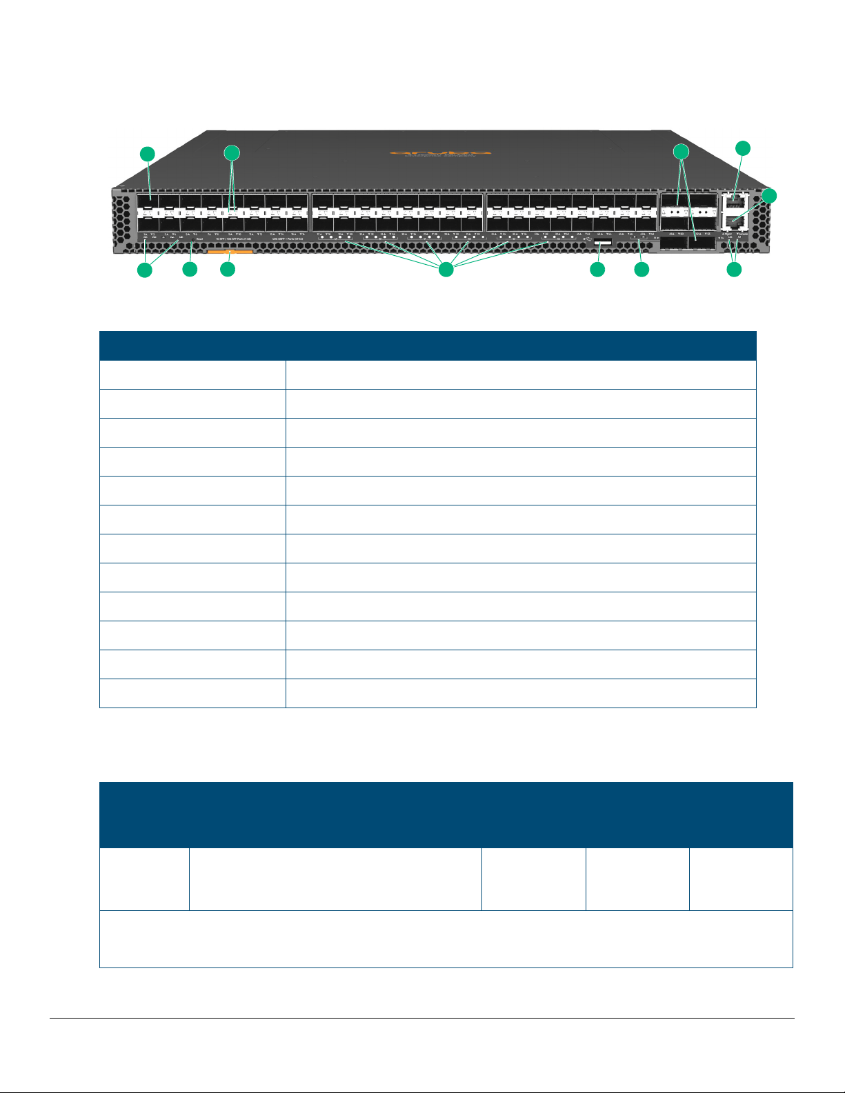
Front of the switch
1
2
4
8 6
5
9
11
12
3
7
10
Figure 1: Front of the Aruba 8320 switch
Table 1: Front of the Aruba 8320 switch labels and descriptions
Label Description
1SFP+ ports
2 SFP+ port LEDs
3 QSFP+ ports
4 10/100/1000Base-T RJ-45 Out-of-Band Management (OOBM) port
5 RJ-45 serial console port
6 Management port LEDs
7 QSFP+ ports 51 and 54 LEDs
8 USB auxiliary port
9 QSFP+ port LEDs
10 Asset tag
11 Reset button
12 Power 1 and 2, Global Status, Unit Identification, and Fan LED
Network ports
Table 2: Network ports
Product
number
JL479A Aruba 8320 48p 10G SFP/SFP+ and 6p 40G
Model name 10/100/1000
non-PoE
RJ-45 ports
–48 6
QSFP+ with X472 5 Fans 2 Power Supply
Switch Bundle
SFP+ ports
1
QSFP+ ports
Notes:
1
SFP+ ports support 1G SFP, and 10G SFP+ transceivers.
6 Aruba 8320 Switch Installation and Getting Started Guide
Page 7

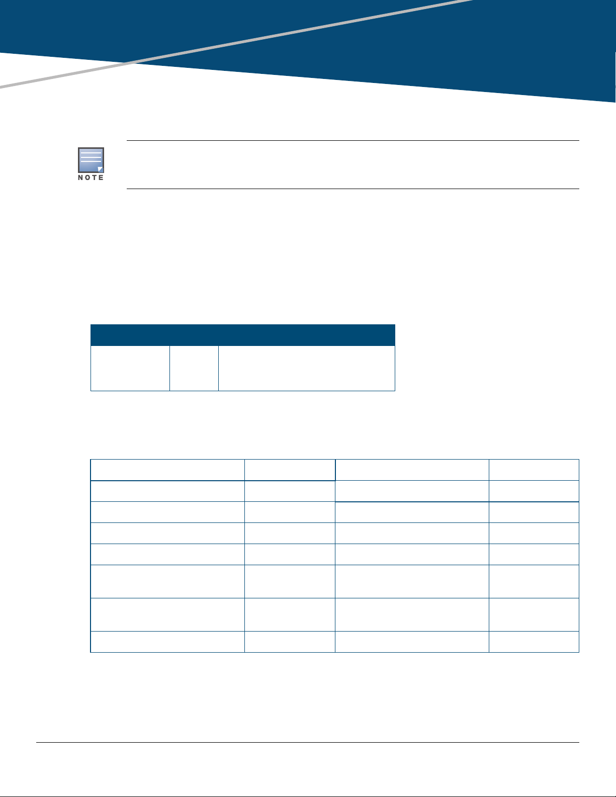
This product also supports optional network connectivity:
Table 3: Optional network connectivity, speeds and technologies
Transceiver form-factor and connector
Speed Technology Cabling SFP ("mini-
GBIC")
SFP+
connector
QSFP+
connector
Connector
1000 Mbps 1000-T Copper (twisted-pair) RJ-45 – –
1000-SX Fiber (multimode)
1000-LX Fiber (multimode or
LC
2
––
LC – –
single mode)
1000-LH Fiber (single mode) LC – –
1000-BX Fiber (single mode) LC – –
10 Gbps 10-Gig
Copper (twinaxial) – – –
Direct Attach
10-Gig SR Fiber (multimode) – LC –
10-Gig LR Fiber (single mode) – LC –
10-Gig ER Fiber (single mode) – LC –
40 Gbps 40-Gig
Copper (twinaxial) – – –
Direct Attach
1
40-Gig SR4 Fiber (multimode) – –
MPO
3
40-Gig ESR4 Fiber (multimode) – – MPO
40-Gig LR4 Fiber (single mode) – – LC
1
For supported transceivers, visit http://www.hpe.com/support/manuals.
• In the first textbox, type J4858 (for Gigabit information), or J8436 (for 10-Gigabit information).
• Select any of the products that display in the dropdown list and click on Show Selected Items.
•Select Support Center. Then click on Manuals, followed by View All to find the Transceiver Support
Matrix.
For technical details of cabling and technologies, see Cabling and technology information
.
For more information, see the ArubaOS-Switch Transceiver Guide at: http://www.hpe.com/support/manuals.
2
The Lucent Connector (LC) is a small form factor fiber optic connector.
3
The Multifiber Push On (MPO) connector is a 12-fiber optical connector.
Chapter 1 Introducing the Aruba 8320 Switch 7
Page 8

Management ports
213 4 5
Console port
There is one RJ-45 serial console port on the switch. This port is used to connect a console to the switch by using
an RJ-45 serial cable. A DB9-to-RJ-45 console cable can be ordered from HPE: JL448A, Aruba X2C2 RJ45 to DB9
Console Cable.
For more information on the console connection, see Connect a management console
or workstation running a VT-100 terminal emulator, or a VT-100 terminal.
. The console can be a PC
Out-of-band management (OOBM) port
This RJ-45 port is used to connect a dedicated management network to the switch. To use it, connect an RJ-45
network cable to the management port to manage the switch through SSH from a remote PC or a UNIX
workstation.
To use this port, see Enabling out-of-band management on the management port
A networked out-of-band connection through the management port allows you to manage data network switches
from a physically and logically separate management network.
For more information, see the Basic Operation Guide and the Management and Configuration Guide for your
switch at www.hpe.com/support/manuals
contact your HPE/Aruba representative. For information on Aruba AirWave, go to www.arubanetworks.com/
products/networking/management/airwave.
. For information on the HPE IMC (Intelligent Management Center),
.
Auxiliary (Aux) port
An auxiliary port for processing a USB command file or downloading switch software code. This port uses a USB
Type A connector, but does not comply with all USB protocols and standards.
Switch and port LEDs on the front of the switch
• Table 5 on page 9 describes the switch chassis LEDs.
• Table 7 on page 10 describes the switch port LEDs and their different behaviors.
Figure 2: Chassis LEDs
Table 4: Chassis LED labels
Label Description
1 Power supply LEDs
8 Aruba 8320 Switch Installation and Getting Started Guide
Page 9

Table 4: Chassis LED labels
Label Description
2 Global status LED
3 Fan LED
4 Unit identification LED
5 Reset button
Table 5: Chassis LED behavior
Chassis LEDs Function State Meaning
PS1/PS2 Power supply status On green Power supply is installed and
operating normally.
Slow flash amber Fault detected for installed
power supply.
Off Power supply is not installed or
not receiving power.
Fan Fan tray status On green System fans are operating
normally.
Global Status Internal power status of
the switch.
Self-test status
Switch/port fault status
Slow flash amber One or more system fans has a
fault, or the minimum number of
fans are not installed.
On green The switch has passed self-test
and is powered up normally.
Slow flash green* The switch self-test and
initialization are in progress
after the switch has been power
cycled or reset. The switch is
not operational until this LED
stops blinking green.
Slow flash amber* A fault or self-test failure has
occurred on the switch, one of
the switch ports, OOBM port,
USB port,console port, power
supplies, or a fan. The Status
LED for the component with the
fault will flash simultaneously.
On amber If this LED is on amber for a
prolonged time, the switch has
encountered a fatal hardware
failure, or has failed its self-test.
Off The unit is not receiving power.
Chapter 1 Introducing the Aruba 8320 Switch 9
Page 10

Table 5: Chassis LED behavior (Continued)
4 53
21
Chassis LEDs Function State Meaning
UID (Unit Identification) The Unit Identification
On or slow flash* The "LED locator on" command
LED is used to help you
to identify a particular
unit in a rack or
collection of products.
Off LED will turn off after the
* The slow blink behavior is an on/off cycle once every 1.6 seconds, approximately.
Figure 3: Port LEDs
Table 6: Port LED labels
allows you to blink or turn on the
LED. The default is 30 minutes.
timeout period has expired.
Label Description
1 QSFP+ port lane 1 LED
2 QSFP+ port lanes 2, 3, and 4 LEDs
3 SFP+ port LEDs
4 Out-of-band management port Link LED
5 Out-of-band management port Act (activity) LED
Table 7: Port LED behavior
Chassis LEDs Function State Meaning
SFP+ port LEDs To display link and
activity information for
the port.
On/Flashing green Shows a valid link at 1 Gbps or
10 Gbps. Flashing indicates port
activity.
Flashing amber Indicates an unsupported
transceiver or a port failure.
10 Aruba 8320 Switch Installation and Getting Started Guide
Page 11

Table 7: Port LED behavior (Continued)
Chassis LEDs Function State Meaning
QSFP+ port 40G LED To display link and
activity information for
the port.
Management port Link
LED
Management port Act
LED
To display link
information for the port.
To display activity
information for the port.
On/Flashing green Shows a valid link at 40 Gbps.
Flashing indicates port activity.
Off When the Global Status LED is
flashing, indicates an
unsupported transceiver or a
port failure.
On green Shows a valid link.
Flashing green Flashing indicates port activity.
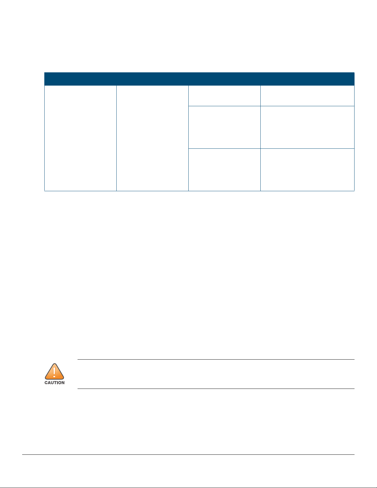
Reset button
The Reset button is recessed from the front panel (to protect it from being pushed accidentally) and is accessible
through a small hole on the front panel. Use a pointed object, such as an unbent paper clip, to push the button.
The Reset button is used as follows:
To accomplish this: Do this: This will happen:
Soft Reset Press and release the Reset
button
The switch operating system is
cleared gracefully (such as data
transfer completion, temporary
error conditions are cleared), and
then reboots.
Hard Reset Press and hold the Reset button
for more than 3 seconds, then
release.
Restore the factory default
configuration
Note: The Reset button is provided for your convenience. If you are concerned with switch security, make
sure that the switch is installed in a secure location, such as a locked wiring closet.
Press and hold the Reset button
for more than 5 seconds (until all
LEDs turn on), then release.
The switch reboots, similar to a
power cycle. A hard reset is used,
for example, when the switch
CPU is in an unknown state or
not responding.
The switch removes all
configuration changes, and
restores the factory default
configuration.
Chapter 1 Introducing the Aruba 8320 Switch 11
Page 12

Back of the switch
2
1
7
654
3
9 8
10
The back of the switch includes two power supply units and five fan trays.
Figure 4: Back of the Aruba 8320 switch
Table 8: Back of the Aruba 8320 switch labels and descriptions
Label Description
1 AC power connector / power supply 2
2 Fan tray 5
3 Fan tray 4
4 Fan tray 3
5 Fan tray 2
6 Fan tray 1
7 AC power connector / power supply 1
8 Fan tray status LED
9 Power supply release latch
10 Power supply status LED
Power supplies
The Aruba 8320 switch does not have a power switch; it is powered on when at least one installed power supply is
connected to an active AC power source. The power supplies automatically adjust to any voltage between 100-127
and 200-240 volts and either 50 or 60 Hz. There are no voltage range settings required.
Never insert or remove a power supply while the power cord is connected. Verify that cord has been
disconnected from the power supply before installation or removal.
The Aruba 8320 switch power supplies adapt electrical power for use with the switch. The chassis has two slots
that can hold individual power supplies to support load sharing, redundancy, and fault tolerance. One power supply
is available for use with the Aruba 8320 switch:
Aruba X371 400W 100-240VAC Power Supply (JL480A)
12 Aruba 8320 Switch Installation and Getting Started Guide
Page 13
The Aruba 8320 switch is shipped with two hot-swappable, field-replaceable, AC power supplies. Each power
supply has a country-specific power cord for connection to an AC power outlet. The switch can operate with one
active power supply.
Power supply status LED
Table 9: Power supply LED behavior
Power supply LED Function State Meaning
Status LED To display power supply
status.
On green The power supply is operating
normally.
On amber The power supply is in standby
mode with AC power
connected. Or, if the Global
Status LED is also flashing,
indicates a failure.
Off AC power is not connected to
the power supply or it is in
protection mode due to a
voltage, current, thermal, or
short-circuit condition.
Load Sharing
Load sharing occurs when two power supplies are installed in the switch and turned on. Load sharing divides the
total power load of the switch among both power supplies. Since the power supplies work together, the effective
power capacity of the switch is increased with the additional power supply.
Redundancy
With power redundancy, the Aruba 8320 switch can continue normal operation even when one power supply fails
or is powered off. When two power supplies are installed, if one becomes unavailable (fails, or is powered off or
removed) the remaining power supply provides full power for the device.
Hot Swapping
Hot swapping allows you to replace one failed power supply while the other provides full power. This makes it
unnecessary to shut down the switch during the replacement procedure.
Fan Trays
The Aruba 8320 switch is equipped with five field-replaceable, hot-swappable fan trays. Each fan tray features
individual fans that pull air through the chassis from the front through to the rear. The switch can tolerate the failure
of a single fan tray while maintaining a safe operating temperature.
The Aruba 8320 switch is not compatible with fan trays from other Aruba hardware platforms.
Chapter 1 Introducing the Aruba 8320 Switch 13
Page 14

Fan tray status LED
Table 10: Fan tray LED behavior
Fan tray LED Function State Meaning
Status LED To display fan tray
status.
On green The fan tray is operating
normally.
On red The fan tray has an error or has
failed.
Switch features
The features of the Aruba 8320 switch includes:
• Combinations of fixed QSFP+ and SFP+ ports, as described under Network ports
• For secure environment, all ports are disabled by default.
• The option to have one or two power supplies: A second power supply supports redundant system power. If
one of the power supplies fails, the second power supply immediately provides the power necessary to keep
the switch running.
• The SFP+ and QSFP+ ports always operate at full duplex.
• Easy management of the switch through several available interfaces:
◦ Command line interface—A full featured, easy to use, VT-100 terminal interface for out-of-band switch
management.
◦ Web browser interface—An easy to use built-in graphical interface that can be accessed from common
web browsers.
◦ Aruba AirWave—A powerful and easy-to-use network operations system that manages wired and
wireless infrastructures. For more information, go to www.arubanetworks.com/products/networking/
management/airwave.
◦ IMC (Intelligent Management Center)—An SNMP-based, graphical network management tool that you
can use to manage your entire network. Free trials of IMC can be downloaded at http://www.hpe.com/
networking/imc.
• Support for the Spanning Tree Protocol to eliminate network loops.
• Support for up to 4096 IEEE 802.1Q-compliant VLANs so you can divide the attached end nodes into logical
groupings that fit your business needs.
• Support for many advanced features to enhance network performance. For a description, see the Aruba 8320
Management and Configuration Guide at www.www.hpe.com/support/manuals
• To download product updates, go to either of the following:
◦ Hewlett Packard Enterprise Support Center Get connected with updates page:
www.hpe.com/support/e-updates
◦ HPE Networking Software: www.hpe.com/networking/software
◦ To view and update your entitlements, and to link your contracts and warranties with your profile, go to the
Hewlett Packard Enterprise Support Center More Information on Access to Support Materials page:
www.hpe.com/support/AccessToSupportMaterials
.
.
14 Aruba 8320 Switch Installation and Getting Started Guide
Page 15
Chapter 2
Installing the switch
This chapter shows how to install the switch. The Aruba 8320 switch comes with an accessory kit that includes the
brackets for mounting the switch in a standard 19-inch telco rack, or in an equipment cabinet.
The Aruba 8320 switch can also be mounted in any four post rack using the Aruba X474 4-Post
Rackmount Bracket Kit (JL483A).
Included parts
The Aruba 8320 switch has the following components shipped with it:
• Aruba Switch Quick Setup Guide and Safety/Regulatory Information
• Switch Safety and Regulatory sheet
• Warranty notice
• General Safety and Regulatory booklet
• JL482A Aruba X472 2-Post Rackmount Bracket Kit
Part number Count Included items
5200-3899 2
8
4
• There are two warranty documents. One is the HPN warranty and the other is the EG warranty.
◦ 5998-5984 Warranty Statement and Software License
◦ 703828-025 EG Safety, Compliance, and Warranty Information
• Power cord, one of the following
Argentina 8121-0729 Israel 8121-1004
Australia/New Zealand 8121-0837 Japan 8121-1143
Brazil 8121-1071 Switzerland 8121-0738
Chile 8121-0735 South Africa 8121-0737
China 8121-0943 Taiwan 8121-0964
Continental Europe/South
Korea
Denmark 8121-0733
Rack mount brackets
Small screws; bracket-to-switch
Large screws; bracket-to-rack
8121-0731 Philippines/Thailand 8121-0734
UK/Hong Kong/Singapore/
Malaysia
8121-0739
India 8121-0564 US/Canada/Mexico 8121-1141
Chapter 2 Installing the switch 15
Page 16

Installation procedures
Summary
1. Prepare the installation site (page 18). Ensure the physical environment into which you will be installing the
switch is properly prepared, including having the correct network cabling ready to connect to the switch and
having an appropriate location for the switch. See Installation precautions
personal injury or product damage when installing your switch.
for some guidelines on avoiding
2. Mount the switch (page 18
3. (Optional) Install SFP/SFP+ transceivers (page 21
QSFP+ transceivers. Depending on where you install the switch, it may be easier to install the transceivers
first. Transceivers can be hot swapped—they can be installed or removed while the switch is powered on.
4. Connect power to the switch (page 23
5. Connect a management console to the switch (page 23
configuration, so it can be managed using a Web browser or through an SSH session. Configuration changes
can be made by using a console cable to connect a PC to the switch’s console port.
6. Connect the network devices (page 25
to the switch ports.
At this point, your switch is fully installed. See the rest of this chapter if you need more detailed information on any
of these installation steps.
). The switch can be mounted in a 19-inch telco rack or in an equipment cabinet.
). The switch has slots for installing SFP/SFP+ and
). Once the switch is mounted, plug it into the main power source.
). You may want to modify the switch’s
). Using the appropriate network cables, connect the network devices
16 Aruba 8320 Switch Installation and Getting Started Guide
Page 17

Installation precautions
To avoid personal injury or product damage when installing your switch, read the installation precautions and
guidelines below.
• Do not mount the switch on a wall, on or under a table, or on or under any other horizontal
surface.
• Mount devices installed in a rack or cabinet as low as possible. Put the heaviest devices at the
bottom and progressively lighter devices installed above.
• To prevent the rack or cabinet from becoming unstable and/or falling over, ensure that it is
adequately secured.
• Ensure the power source circuits are properly grounded. Then connect the switch to the power
source by using the power cord supplied with the switch.
• If your installation requires a different power cord than the one supplied with the switch and power
supply, be sure the cord is adequately sized for the switch’s current requirements. In addition, be
sure to use a power cord displaying the mark of the safety agency that defines the regulations for
power cords in your country. The mark is your assurance that the power cord can be used safely
with the switch and power supply.
• When installing the switch, the AC outlet should be near the switch and be easily accessible in
case the switch must be powered off.
• Do not install the switch in an environment where the operating ambient temperature exceeds its
specification. (See the Environmental Operating Temperature
• Ensure that the switch does not overload the power circuits, wiring, and over-current protection.
To determine the possibility of overloading the supply circuits, add the ampere ratings of all
devices installed on the same circuit as the switch. Then compare the total with the rating limit for
the circuit. The maximum ampere ratings are usually printed on the devices near the AC power
connectors.
• Ensure that the air flow around the switch is not restricted. Leave at least 3 inches (7.6 cm) for
cooling.
information.)
If a power supply must be removed, and then reinstalled, wait at least 5 seconds before reinstallation.
Otherwise, damage to the switch may occur.
The power supply needs this time to bleed off any retained power.
Chapter 2 Installing the switch 17
Page 18

1. Prepare the installation site
Cabling Infrastructure - Ensure the cabling infrastructure meets the necessary network specifications. See
chapter 7, Cabling and technology information
Installation Location - Before installing the switch, plan its location and orientation relative to other devices and
equipment:
• In the front of the switch, leave at least 3 inches (7.6 cm) of space for the twisted-pair and fiber-optic cabling.
• In the back of the switch, leave at least 3 inches (7.6 cm) of space for the power cord.
• On the sides of the switch, leave at least 3 inches (7.6 cm) for cooling.
for more information:
2. Mount the switch
Mounting an Aruba 8320 switch
The supported mounting options for the Aruba 8320 switch includes:
• Two-post rack mount (JL482A; included)
• Four-post rack mount (JL483A; sold separately)
Two-post rack mount option:
The switch is designed to be mounted in any EIA-standard 19-inch telco rack or communication equipment cabinet
using the Aruba X472 2-Post Rackmount Bracket Kit(JL482A; included).
The mounting brackets must only be attached for mid-mounting the switch in a two-post rack. Secure the rack in
accordance with the manufacturer’s safety guidelines.
For safe operation, please read the mounting precautions in Installation precautions
mounting a switch.
The 12-24 screws supplied with the switch are the correct threading for standard EIA/TIA open 19inch racks. If installing the switch in an equipment cabinet such as a server cabinet, use the clips
and screws that came with the cabinet in place of the 12-24 screws that are supplied with the switch.
Complete step 1, and plan which four holes you will be using in the cabinet and install all four clips.
Then proceed to step 2.
1. Use a #1 Phillips (cross-head) screwdriver and attach the mounting brackets to the switch with the included
eight 8-mm M4 screws.
The brackets must only be attached for mid-mounting the switch in a two-post rack. Ensure the holes in the
bracket are aligned with the correct holes in the switch, as per the diagram.
, before
18 Aruba 8320 Switch Installation and Getting Started Guide
Page 19

Figure 5: Attaching two-post mounting brackets to the switch
For safe reliable installation, only use the screws provided in the accessory kit to attach the
mounting brackets to the switch.
2. Hold the switch with attached brackets up to the rack, move it vertically until rack holes line up with the bracket
holes, and then insert and tighten the four number 12-24 screws holding the brackets to the rack.
Figure 6: Mounting the switch in a two-post rack
Four-post rack mount option:
The Aruba 8320 switch can be mounted in four-post racks and cabinets by using the Aruba X474 4-Post
Rackmount Bracket Kit (JL483A); sold separately.
The JL483A Aruba X474 4-Post Rackmount Bracket Kit includes these items:
• two front-post brackets
• two rear-post brackets with adjustable ears
• twenty 8-mm M4 screws
• eight 5/8-inch number 12-24 screws
Chapter 2 Installing the switch 19
Page 20

• two rear bracket ear position-locking screws
The brackets must only be attached for front-flush mounting the switch in a four-post rack. Secure the rack in
accordance with the manufacturer’s safety guidelines.
For safe operation, please read the mounting precautions in Installation precautions
mounting a switch.
The 12-24 screws supplied with the switch are the correct threading for standard EIA/TIA open 19inch racks. If installing the switch in an equipment cabinet such as a server cabinet, use the clips
and screws that came with the cabinet in place of the 12-24 screws that are supplied with the switch.
Complete step 1, and plan which holes you will be using in the cabinet and install all four clips. Then
proceed to step 2.
1. Use a #1 Phillips (cross-head) screwdriver and attach the front- and rear-post rack mount brackets to the
switch with the included 8-mm M4 screws.
Figure 7: Attaching four-post mounting brackets to the switch
, before
For safe reliable installation, only use the screws provided in the accessory kit to attach the
mounting brackets to the switch.
2. For the rear-post brackets, use an additional two 8-mm M4 screws to secure the bracket at the mid-point on
the side of the switch.
3. Hold the switch with attached brackets up to the rack, move it vertically until rack holes line up with the front-
post bracket holes, and then insert and tighten the four number 12-24 screws holding the brackets to the rack.
20 Aruba 8320 Switch Installation and Getting Started Guide
Page 21

Figure 8: Mounting the switch in a four-post rack
4. Adjust the rear-post bracket ears to fit the depth of the rack.
5. Secure the rear-post brackets to the rack rear posts using four number 12-24 screws.
6. Lock the position of the rear-post bracket ears using the included position-locking screws.
Figure 9: Locking the position of rear-post brackets
3. Install transceivers
You can install or remove a transceiver from an SFP+/QSFP+ slot without having to power off the switch.
• The transceivers operate only at full duplex. Half duplex operation is not supported.
• Ensure the network cable is NOT connected when you install or remove a transceiver.
Chapter 2 Installing the switch 21
Page 22

Use only supported genuine Aruba SFP/SFP+/QSFP+ transceivers with your switch. Non-Aruba SFP/
SFP+/QSFP+ transceivers are not supported, and their use may result in product malfunction. Should
you require additional transceivers, contact your Aruba sales representative or an authorized reseller.
The following resources can help you to find transceiver support information for your switch model:
• See the ArubaOS-Switch and ArubaOS-CX Transceiver Guide in the Hewlett Packard Enterprise
Information Library at http://www.hpe.com/support/manuals
• See the supported transceivers information in the QuickSpecs for your switch model at
http://www.hpe.com/support/manuals
listed transceivers:
1. Select Switches.
2. Select Aruba Switches.
3. Select a switch model.
4. Select Product Details.
5. Select an option under QuickSpecs.
, along with minimum software versions to support the
.
Installing transceivers:
Hold the transceiver by its sides and gently insert it into either of the slots on the switch until it clicks into place.
When a transceiver is inserted the switch authenticates it. This can take 1-3 seconds, with the worst case being 5
seconds. If the transceiver is removed before the authentication completes a self test failure will be reported.
The fiber Aruba transceivers are Class 1 laser devices. Avoid direct eye exposure to the beam
coming from the transmit port.
Figure 10: Installing a transceiver
Removing transceivers:
Depending on when the transceiver was purchased, it may have either of three different release mechanisms:
• A plastic tab on the bottom of the transceiver
• A plastic collar around the transceiver
•A wire bail
22 Aruba 8320 Switch Installation and Getting Started Guide
Page 23

To remove the transceivers that have the plastic tab or plastic collar, push the tab or collar toward the switch until
the transceiver releases from the switch (it will move outward slightly), then pull it from the slot.
To remove the transceivers that have the wire bail, lower the bail until it is approximately horizontal, and then using
the bail, pull the transceiver from the slot.
4. Connect the switch to a power source
1. If a power supply is not already installed in the switch, install at least one power supply. (See the Aruba Switch
Power Supply Quick Setup Guide and Safety/Regulatory Information document shipped with your power
supply units.) The Aruba 8320 switch uses any of the following power supplies:
• Aruba X371 400W 100-240VAC Power Supply (JL480A)
2. Plug the included power cord into the power supply’s power connector and into a nearby AC power source.
Figure 11: Connecting a power cord to the switch
3. Check the LEDs. See Switch and port LEDs on the front of the switch
One power supply provides power to operate the switch. Installing a second power supply can
provide power to the switch in case the initial power supply fails. If the power supplies are plugged
into different AC power sources, redundant power can be supplied in case of loss of one of the AC
power sources.
.
5. Connect a management console
The Aruba 8320 switch has a full-featured, easy to use console interface for performing switch management tasks,
including the following:
• Enabling switch ports (ports are disabled by default).
• Monitoring switch and port status and observing network activity statistics.
• Modifying the switch’s configuration to optimize switch performance, enhancing network traffic control, and
improving network security.
• Reading the event log and accessing diagnostic tools to help in troubleshooting.
• Downloading new software to the switch.
• Adding passwords to control access to the switch from the console, Web browser interface, and network
management stations.
Chapter 2 Installing the switch 23
Page 24

The console can be accessed through these methods:
• Out-of-band serial: Use a serial cable (not included) for connecting a workstation running suitable VT-100
terminal emulation software directly to the switch’s RJ-45 Console Port. A DB9-to-RJ-45 console cable can be
ordered from HPE: JL448A, Aruba X2C2 RJ45 to DB9 Console Cable.
• Out-of-band network: Access the console using SSH from a PC or UNIX station on the network running
suitable VT-100 terminal emulation software. For more information, see chapter 3, Getting started with
switch configuration.
The switch can simultaneously support one console session through the Console Port and multiple network
SSH sessions.
Terminal configuration
To connect a console to the switch, configure the PC terminal emulator as a DEC VT-100 (ANSI) terminal or use a
VT-100 terminal, and configure either one to operate with these settings:
• A baud rate of 115200.
• 8 data bits, 1 stop bit, no parity, and flow control set to off.
• For the Windows Terminal program, also disable (uncheck) the “Use Function, Arrow, and C
Windows” option.
• For the Hilgraeve HyperTerminal program, select the “Terminal keys” option for the “Function, arrow, and ctrl
keys act as” parameter.
If you want to operate the console using a different configuration, make sure you change the settings on both the
terminal and on the switch so they are compatible. Change the switch settings first, then change the terminal
settings, then reboot the switch and reestablish the console session.
trl Keys for
Direct console access
To connect a console to the switch, follow these steps:
1. Connect the PC or terminal to the switch’s Console Port using a console cable (JL448A; sold separately).
Figure 12: Connecting a console cable
2. Turn on the terminal or PC’s power and, if using a PC, start the PC terminal program.
3. Press [Enter] two or three times. When prompted to log in specify admin. When prompted for the password,
press [Enter]. (By default, no password is defined.)
You are placed into the manager command context, which is identified by the prompt: switch#. For example:
login as: admin
Password:
24 Aruba 8320 Switch Installation and Getting Started Guide
Page 25

switch#
12345678
5 4 3 2 1
9 8 7 6
If you want to continue with console management of the switch at this time, see chapter 3, Getting started with
switch configuration for some basic configuration steps. For more detailed information, refer to the Basic
Operation Guide and the Manangement and Configuration Guide, which are on the Hewlett Packard Enterprise
Web site at www.hpe.com/support/manuals
.
Console cable pinouts
The Aruba X2C2 RJ45 to DB9 Console Cable (JL448A) has an RJ-45 plug on one end and a DB-9 female
connector on the other end. Tab l e 11
Figure 13: RJ-45 to DB-9 pinouts
Table 11 : Mapping of RJ-45 to DB-9
RJ-45 (Signal reference from Chassis) DB-9 (Signal reference from PC)
Reserved 1 8 CTS
describes the mapping of the RJ-45 to DB-9 pins.
Reserved 2 6 DSR
TXD 3 2 RXD
Reserved 4 1 DCD
GND 5 5 GND
RXD 6 3 TXD
Reserved 7 4 DTR
Reserved 8 7 RTS
––9RI
6. Connect the network cables
Connect the network cables, described under “Cabling Infrastructure” (1. Prepare the installation site), from the
network devices or your patch panels to the RJ-45 out-of-band management port on the switch or to any
transceivers you have installed in the switch.
Using the RJ-45 out-of-band management port
If you plan to manage the switch from a dedicated management network, connect an RJ-45 network cable from the
management network to the Mgmt port. The Mgmt port supports 10, 100, and 1000 Mbps connections.
To connect:
Push the RJ-45 plug into the RJ-45 port until the tab on the plug clicks into place. When power is on for the switch
and for the connected device, the Link LED for the port should light to confirm a powered-on device (for example,
an end node) is at the other end of the cable.
Chapter 2 Installing the switch 25
Page 26

If the Link LED does not go on when the network cable is connected to the port, see Diagnosing with the LEDs
chapter 5, “Troubleshooting”.
To disconnect:
Press the small tab on the plug and pull the plug out of the port.
Figure 14: Connecting an RJ-45
Connecting cables to SFP/SFP+/QSFP+ transceivers
in
If you have any transceivers installed in the switch, the type of network connections you will need to use depends
on the type of transceivers installed. See chapter 6, Cabling and technology information
For transceiver ports, and in general for all the switch ports, a network cable from an active network device is
connected to the port. If the port LED does not come on half-bright when the network cable is connected to the
port, see Diagnosing with the LEDs
Figure 15: Connecting cable to a transceiver
in chapter 5, “Troubleshooting.”
, for cabling information.
26 Aruba 8320 Switch Installation and Getting Started Guide
Page 27

Chapter 3
Getting started with switch configuration
This chapter is a guide for using the console CLI to quickly assign an IP (Internet Protocol) address and subnet
mask to the switch, set a Manager password, and, optionally, configure other basic features.
For more information on using the switch console, see the Basic Operation Guide and the Management and
Configuration Guide for your switch at www.hpe.com/support/manuals
(Intelligent Management Center), contact your HPE/Aruba representative. For information on Aruba AirWave, go to
www.arubanetworks.com/products/networking/management/airwave
. For information on the HPE IMC
.
Recommended minimal configuration
In the factory default configuration, the switch is optimized for secure deployments. It has no IP (Internet Protocol)
address and subnet mask, all network ports are administratively shut down, the OOBM port is shut down, remote
management protocols are disabled, and there is a default admin user account with no password configured. To
manage the switch via a networked connection attached to the out-of-band management port, you must first
enable the port and configure the switch with an IP address and subnet mask compatible with your network You
must also configure a Manager password before enabling remote access methods such as SSH and the Web
browser interface.
All switch port interfaces are disabled by default, you first need to enable all switch ports that you intend to use for
network connections.
Many other features can be configured through the switch’s console interface to optimize the switch’s performance,
to enhance your control of the network traffic, and to improve network security. Once an IP address has been
configured on the switch, these features can be accessed more conveniently through a remote SSH session,
through the switch’s Web browser interface, and from an SNMP network management station running network
management software. For a listing of switch features available with and without an IP address, refer to “How IP
Addressing Affects Switch Operation” in the Management and Configuration Guide.
For more information on configuring IP addressing, refer to the Basic Operation Guide at www.hpe.com/support/
manuals.
By default, the switch is configured to acquire an IP address configuration from a DHCP or Bootp
server. To use DHCP/Bootp instead of the manual method described in this chapter, see “DHCP/
Bootp Operation” in the Management and Configuration Guide.
Using the console CLI
The quickest and easiest way to minimally configure the switch for management and password protection in your
network is to use a direct console connection to the switch and start a console session.
1. Using the method described in Terminal configuration
the switch console command line interface (CLI) prompt (the default display).
The CLI prompt appears, for example:
, connect a terminal device to the switch and display
switch#
2. Enter the command config to change to the global configuration context: switch (config)#. For
example:
switch# config
switch(config)#
Chapter 3 Getting started with switch configuration 27
Page 28

3. Define a password for the default admin account with the command user admin password. The local
account password can contain up to 32 alphanumeric characters within the printable ASCII character-set.
Spaces are not allowed. ASCII characters from hex 21 to hex 7E [\x21-\x7E] are allowed.
For example:
switch(config)# user admin password
Changing password for user admin
Enter password:************
Confirm password:************
4. Save the switch configuration changes by using the copy command.
switch# copy running-config startup-config
Enabling out-of-band management on the management port
The management port is disabled by default. Once enabled, it uses SSH to authenticate user logins and provided
a secure connection for remote management. You must assign a password to the default admin account to enable
SSH.
1. Enable the out-of-band management port using the following commands:
switch# configure
switch(config)# interface mgmt
switch(config-if-mgmt)# no shutdown
2. Enable the SSH server on the management VRF (mgmt) with the command ssh server vrf mgmt. By
default, the SSH server will authenticate logins using the locally defined user accounts.
For example:
switch(config)# ssh server vrf mgmt
3. By default, management interface is set to operate as a DHCP client. If you prefer to use static addressing,
define an IP address, default gateway, and DNS server with the commands ip, default-gateway, and
nameserver.
For example, these commands set the management IP to 192.168.1.10 with a mask of 24 bits, the default
gateway to 192.168.1.100, and the DNS server to 192.168.1.99:
switch(config)# interface mgmt
switch(config-if-mgmt)# ip static 192.168.1.10/24
switch(config-if-mgmt)# default-gateway 192.168.1.100
switch(config-if-mgmt)# nameserver 192.168.1.99
You can specify IPv6 addresses instead of IPV4 addresses if required by your network.
4. Log out of the switch with the commands end and exit.
5. Use an Ethernet cable to connect the management port to your network.
6. Use an Ethernet cable to connect your computer to the same network.
7. Start your SSH client software and configure a new session using the address assigned to the management
port in step 2. You should now be able to establish a connection to the management port using SSH client
software. When prompted, login with the admin account.
8. The switch can also be managed through a web browser interface using the address assigned to the
management port in step 2. Use the command https-server to enable the web server and set the access
mode, and then establish a connection to the management port using a web browser.
switch(config)# https-server vrf mgmt
switch(config)# https-server rest access-mode read-write
When prompted, login with the admin account.
28 Aruba 8320 Switch Installation and Getting Started Guide
Page 29

Figure 16: Web browser interface home page
Where to go from here
The above procedure configures your switch with a Manager password, IP address, and subnet mask. As a result,
with the proper network connections, you can now manage the switch from a PC equipped with SSH and/or a web
browser interface.
Some basic information on managing your switch is included in the next section. For more information on the
console, web browser, and SNMP management interfaces and all the features that can be configured on the
switch, see the Basic Operation Guide and the Management and Configuration Guide at www.hpe.com/support/
manuals.
Software updates
See Accessing updates.
To recover from a lost manager password:
If you cannot start a console session at the manager level because of a lost Manager password, you can clear all
passwords and user names by getting physical access to the switch and pressing and holding the Reset button for
more than 5 seconds. See Reset button
.
Chapter 3 Getting started with switch configuration 29
Page 30

Chapter 4
2
1
2
1
Replacing components
This chapter shows you how to remove and install the following components:
• Power supply
• Fan tray
The power supplies and fan trays are hot swappable. You do not need to power off the switch before installing or
replacing a power supply or fan tray.
The Aruba 8320 switch and its components are sensitive to static discharge. Use an antistatic wrist strap and
observe all static precautions when replacing components.
If a power supply must be removed and then reinstalled, wait at least 5 seconds before reinstallation. Otherwise,
damage to the switch may occur. The power supply needs this time to bleed off any retained power.
Replacing a power supply
If the Aruba 8320 switch is configured with a redundant power supply, the switch will not suffer any loss of traffic or
performance if a power supply fails. To maintain system redundancy, a failed power supply should be replaced as
soon as possible. The PS1 or PS2 LED will be on amber and flash simultaneously with the switch Global Status
LED indicating a power supply has failed.
One power supply is available for use with the switch: Aruba X371 400W 100-240VAC Power Supply (JL480A)
To remove a power supply:
1. Remove the AC power cable from the failed power supply’s connector.
2. Grasping the handle of the failed power supply, release the locking mechanism by squeezing the latch handle
while removing the failed power supply.
Figure 17: Replacing a failed power supply
Table 12: Replacing a failed power supply labels and descriptions
Label Description
1 Power supply handle
2 Release latch
Chapter 4 Replacing components 30
Page 31

3. Insert the new power supply. Slide it in all the way in until the locking mechanism clicks into place.
2
1
4. Connect the AC power cable to the new power supply’s connector.
Replacing a fan tray
The Aruba 8320 switch is equipped with five field-replaceable, hot-swappable fan trays. The switch can tolerate the
failure of a single fan tray while maintaining a safe operating temperature. To maintain system redundancy, a failed
fan tray should be replaced as soon as possible. The Fan LED will be on amber and blink simultaneously with the
switch Global Status LED indicating a fan tray has failed.
One fan tray is available for use with the switch: Aruba X721 Front-to-Back Fan (JL481A)
The Aruba 8320 switch is not compatible with fan trays from other Aruba hardware platforms.
To replace a fan tray:
1. Identify the failed fan tray by its status LED. The fan tray LED will be on amber.
2. Remove the new fan tray from its packaging, being careful to not touch any of the circuitry on the board.
3. Loosen the retaining screw on the fan tray.
4. Grasping the handle of the failed fan tray, pull it straight out to remove it from its slot.
5. Insert the new fan tray fully into the slot so that its face plate is flush with the back face of the switch. If the
switch is connected to an AC power source, the fan tray should immediately start running.
6. Engage the retaining screw and tighten it. Be sure to not over-tighten the screw.
Figure 18: Replacing a failed fan tray
Table 13: Replacing a failed fan tray labels and descriptions
Label Description
1 Fan tray retaining screw
2 Fan tray handle
Chapter 4 Replacing components 31
Page 32

Chapter 5
Troubleshooting
This chapter describes how to troubleshoot your switch. This document describes troubleshooting mostly from a
hardware perspective. You can perform more in-depth troubleshooting on these devices using the software tools
available with the switches, including the full-featured console interface, the built-in web browser interface, and
IMC, the SNMP-based network management tool, or Aruba AirWave. For more information, see the chapter
“Troubleshooting” in the Management and Configuration Guide, which is on the Hewlett Packard Enterprise
website at www.hpe.com/support/manuals
This chapter describes the following:
.
• Basic troubleshooting tips (see Basic troubleshooting tips
• Diagnosing with the LEDs (see Diagnosing with the LEDs
• Hardware diagnostic tests (see Hardware diagnostic tests
• Restoring the factory default configuration (see Restoring the factory default configuration
• Downloading new software to the switch (see Downloading new switch software
• Hewlett Packard Enterprise Customer Support Services (see Hewlett Packard Enterprise Customer
Support Services)
)
)
)
)
)
Basic troubleshooting tips
Most problems are caused by the following situations. Check for these items first when starting your
troubleshooting:
• Faulty or loose cables. Look for loose or obviously faulty connections. If the cables appear to be OK, make
sure the connections are snug. If that does not correct the problem, try a different cable.
• Non-standard cables. Non-standard and miswired cables may cause network collisions and other network
problems, and can seriously impair network performance. Use a new correctly-wired cable or compare your
cable to the cable in chapter 7, Cabling and technology information
category 5 cable tester is a recommended tool for every 100BASE-TX and 1000BASE-T network installation.
• Improper network topologies. It is important to make sure you have a valid network topology. Common
topology faults include excessive cable length and excessive repeater delays between end nodes. If you have
network problems after recent changes to the network, change back to the previous topology. If you no longer
experience the problems, the new topology is probably at fault.
In addition, you should make sure that your network topology contains no data path loops. Between any two
end nodes, there should be only one active cabling path at any time. Data path loops can cause broadcast
storms that will severely impact your network performance.
for pinouts and correct cable wiring. A
For your switch, if you want to build redundant paths between important nodes in your network to provide some
fault tolerance, you should enable Spanning Tree Protocol support on the switch. This ensures that only one
of the redundant paths is active at any time, thus avoiding data path loops. Spanning Tree can be enabled
through the switch console or the web browser interface. For more information on Spanning Tree, see the
Advanced Traffic Management Guide for your switch at www.hpe.com/support/manuals
Chapter 5 Troubleshooting 32
.
Page 33

Diagnosing with the LEDs
Table 14 shows LED patterns on the switch that indicate problem conditions for general switch operation
troubleshooting.
LED patterns for general switch troubleshooting
1. Check in the table for the LED pattern you see on your switch.
2. Refer to the corresponding diagnostic tip on the next few pages.
Table 14: LED error indicators
LED Pattern Indicating Problems
Global Status Port LED
Off with power cord plugged in – 1
Solid amber – 2
Slow flash amber – 3
Slow flash amber
Solid green Off with cable connected 5
Solid green On, but the port is not communicating 6
1
The flashing behavior is an on/off cycle once every 1.6 seconds, approximately.
Slow flash amber
1
Diagnostic tips:
Tip Problem Solution
1 The switch is not
plugged into an active
AC power source, or the
switch’s power supply
may have failed.
Verify the power cord is plugged into an active power source and to the
switch. Make sure these connections are snug.
Try power cycling the switch by unplugging and plugging the power cord back
in.
If the Global Status LED is still not on, verify the AC power source works by
plugging another device into the outlet. Or try plugging the switch into a
different outlet or try a different power cord.
Diagnostic Tip
4
If the power source and power cord are OK and this condition persists, the
switch power supply may have failed. Call your Hewlett Packard Enterpriseauthorized network reseller, or use the electronic support services from
Hewlett Packard Enterprise to get assistance.
2 A switch hardware
failure has occurred. All
the LEDs will stay on
indefinitely.
Chapter 5 Troubleshooting 33
Try power cycling the switch. If the fault indication reoccurs, the switch may
have failed. Call your Hewlett Packard Enterprise-authorized network reseller,
or use the electronic support services from Hewlett Packard Enterprise to get
assistance.
Page 34

Tip Problem Solution
3 The switch has
experienced a software
failure during self test,
or one of the switch
cooling fans may have
failed.
4 The network port for
which the LED is
flashing has
experienced a self test
or initialization failure.
Try resetting the switch by pressing the Reset button on the front of the switch,
or by power cycling the switch.
If the fault indication reoccurs, attach a console to the switch (as indicated in
chapter 2) and configure it to operate at 115200 baud. Then, reset the switch.
Messages should appear on the console screen and in the console log
identifying the error condition. You can view the console log at that point by
typing “Show events” at the Manager command prompt (#).
The error may indicate that one of the fans has failed. In switches with multiple
fans the switch may continue to operate under this condition if the ambient
temperature does not exceed normal room temperature, but for best
operation, the failed fan tray should be replaced.
If necessary to resolve the problem, contact your Hewlett Packard Enterpriseauthorized network reseller, or use the electronic support services from
Hewlett Packard Enterprise to get assistance.
If the port is an SFP/SFP+/QSFP+ transceiver, verify that it is one of the
transceivers supported by the switch. Unsupported transceivers will be
identified with this fault condition. The supported transceivers are listed in
Chapter 1, Introducing the Aruba 8320 Switch
tested when they are “hot-swapped”—installed or changed while the switch is
powered on.
To verify the port has failed, remove and reinstall the transceiver without
powering off the switch. If the port fault indication reoccurs, check the event
log to see why the transceiver failed. You may have to replace the transceiver.
Try power cycling the switch. Call your Hewlett Packard Enterprise-authorized
network reseller, or use the electronic support services from Hewlett Packard
Enterprise to get assistance.
. The transceivers are also
34 Aruba 8320 Switch Installation and Getting Started Guide
Page 35

Tip Problem Solution
5 The network connection
is not working properly.
Try the following procedures:
For the indicated port, verify that both ends of the cabling, at the switch and
the connected device, are connected properly.
Verify the connected device and switch are both powered on and operating
correctly.
Verify you have used the correct cable type for the connection:
For fiber-optic connections, verify the transmit port on the switch is connected
to the receive port on the connected device, and the switch receive port is
connected to the transmit port on the connected device.
The cable verification process must include all patch cables from any end
devices, including the switch, to any patch panels in the cabling path.
Verify the port has not been disabled through a switch configuration change.
You can use the console interface, or, if you have configured an IP address on
the switch, use the Web browser interface to determine the state of the port
and re-enable the port if necessary.
Verify the switch port configuration matches the configuration of the attached
device. For example, if the switch port is configured as “Full-duplex”, the port
on the attached device also MUST be configured as “Full-duplex”. If the
configurations don’t match, the results could be a very unreliable connection,
or no link at all.
If the other procedures don’t resolve the problem, try using a different port or a
different cable.
6 The port may be
improperly configured,
or the port may be in a
“blocking” state by the
normal operation of the
Spanning Tree, LACP,
or IGMP features.
Use the switch console to see if the port is part of a dynamic trunk (through the
LACP feature) or to see if Spanning Tree is enabled on the switch, and to see
if the port may have been put into a “blocking” state by those features. The
show lacp interfaces command displays the port status for the LACP
feature; the show spanning-tree command displays the port status for
Spanning Tree.
Also check the Port Status screen using the show interfaces command to
see if the port has been configured as “disabled”.
Other switch features that may affect the port operation include VLANs and
IGMP. Use the switch console to see how the port is configured for these
features.
For software troubleshooting tips, see the chapter “Troubleshooting” in the
Management and Configuration Guide, which is on the Hewlett Packard
Enterprise website at www.hpe.com/support/manuals
Ensure also, that the device at the other end of the connection is indicating a
good link to the switch. If it is not, the problem may be with the cabling
between the devices or the connectors on the cable.
.
Chapter 5 Troubleshooting 35
Page 36

Hardware diagnostic tests
Testing the switch by resetting it
If you believe the switch is not operating correctly, you can reset the switch to test its circuitry and operating code.
To reset a switch, either:
• unplug and plug in the power cord (power cycling)
• press the Reset button on the front of the switch
• reboot the switch via the management console’s boot system command.
Power cycling the switch and pressing the Reset button both cause the switch to reset. These reset processes
also cause any network traffic counters to be reset to zero, and cause the System Up Time timer to reset to
zero.
Checking the switch LEDs
See Diagnosing with the LEDs for information on interpreting the LED patterns.
Checking console messages
Useful diagnostic messages may be displayed on the console screen when the switch is reset. As described in
chapter 2 under step 6, connect a PC running a VT-100 terminal emulator program to the switch’s Console Port
and configure it to run at 115200 baud, and with the other terminal communication settings shown in Terminal
configuration. Then, when you reset the switch, note the messages that are displayed. Additionally, you can
check the switch event log, which can be accessed from the console using the show events command.
Testing switch-to-device network communications
You can perform the following communication tests to verify the network is operating correctly between the switch
and any connected device that can respond correctly to the communication test.
• Link Test—a physical layer test that sends IEEE 802.2 test packets to any device identified by its MAC
address
• Ping Test—a network layer test used on IP networks that sends test packets to any device identified by its IP
address
These tests can be performed through the switch console interface from a terminal connected to the switch or
through a Telnet connection, or from the switch’s web browser interface. For more information, see the Basic
Operation Guide, which is on the Hewlett Packard Enterprise website at www.hpe.com/support/manuals
.
Testing end-to-end network communications
Both the switch and the cabling can be tested by running an end-to-end communications test—a test that sends
known data from one network device to another through the switch. For example, if you have two PCs on the
network that have LAN adapters between which you can run a link-level test or Ping test through the switch, you
can use this test to verify that the entire communication path between the two PCs is functioning correctly. See
your LAN adapter documentation for more information on running a link test or Ping test.
36 Aruba 8320 Switch Installation and Getting Started Guide
Page 37

Restoring the factory default configuration
As part of your troubleshooting process on the switch, it may become necessary to return the switch configuration
to the factory default settings. This clears any passwords, clears the console event log, resets the network counters
to zero, and reboots the switch into its factory default configuration including deleting the IP address, if one is
configured.
This process removes all switch configuration changes that you have made from the factory default
settings. This includes, for example, configuration of VLANs, Spanning Tree, and LAGs. Returning
the configuration of these features to their factory default settings (usually disabling them) may result
in network connectivity issues.
If the switch has a valid configuration, and you are restoring the factory default settings for a reason
other than configuration problems, you should save the switch configuration prior to performing the
factory default reset. Then, after the reset and resolution of the original problem, you can restore the
saved configuration to the switch.
You can restore the factory default configuration either on the switch itself, or through the switch console.
To execute the factory default reset on the switch, perform these steps:
1. Using a pointed object, press the Reset button on the front of the switch.
2. When the Global Status LED begins to fast flash orange (after approximately 5 seconds), release the Reset
button.
The switch will then begin operating with its configuration restored to the factory default settings.
To restore the factory default configuration using the console, execute the erase startup-config command
from the console command prompt.
Downloading new switch software
Software Updates can be downloaded to the switch through several methods. See Accessing updates.
Hewlett Packard Enterprise Customer Support Services
If you are still having trouble with your product, see Support and other resources.
Chapter 5 Troubleshooting 37
Page 38

Specifications
Switch specifications
Physical
Product Width Depth Height Weight
Chapter 6
Aruba 8320 48p 10G
SFP/SFP+ and 6p 40G
QSFP+ with X472 5 Fans
2 Power Supply Switch
Bundle (JL479A)
44.25 cm (17.42 in) 47.15 cm (18.56 in) 4.40 cm (1.73 in) 8.95 kg (19.73 lb)
Electrical
Product AC Voltage Maximum
current
Aruba X371 400W 100-240VAC Power Supply
(JL480A)
*
The power supply automatically adjusts to any voltage between 100-240 volts and either 50 or 60 Hz.
*
100-240 volts 6 A - 3 A 50-60 Hz
Frequency
range
Power Consumption
Product Power consumption
Aruba 8320 48p 10G SFP/SFP+ and 6p 40G QSFP+ with
X472 5 Fans 2 Power Supply Switch Bundle (JL479A)
Max: 357.37 W
Idle: 267 W
Aruba X371 400W 100-240VAC Power Supply (JL480A) Max: 400 W
Aruba X721 Front-to-Back Fan (JL481A) Max: 18 W
MTBF
Product
Aruba 8320 48p 10G SFP/SFP+ and 6p 40G QSFP+ with
X472 5 Fans 2 Power Supply Switch Bundle (JL479A)
Aruba X371 400W 100-240VAC Power Supply (JL480A) 3,318,409 hours
Aruba X721 Front-to-Back Fan (JL481A) 131,916 hours
Chapter 6 Specifications 38
MTBF
115,546 hours
Page 39

Environmental
Operating Non-Operating
Temperature 0°C to 40°C (32°F to 104°F) up to 3.0 km
(10,000 ft)
Relative humidity
(non-condensing)
Maximum altitude 3.0 km (10,000 ft)* 4.6 Km (15,000 ft)
* The operating maximum altitude should not exceed that of any accessory being connected to any Aruba 8320
switch.
5% to 95% at 40°C (104°F) noncondensing
-40°C to 70°C (-40°F to 158°F) up to 4.6 km
(15,000 ft)
5% to 95% at 65°C (149°F)
Acoustics
Switch Model Acoustics
Aruba 8320 48p 10G SFP/SFP+ and 6p 40G QSFP+ with
X472 5 Fans 2 Power Supply Switch Bundle (JL479A)
Sound Pressure (LpAm) (Bystander) 61.1 dB
Safety
• EN 60950-1:2006+A11:2009+A1:2010+A12:2011+A2:2013
• IEC 60950-1:2005 Ed.2; Am 1:2009+A2:2013
• UL 60950-1, CSA 22.2 No 60950-1
• EN 60825-1:2007 / IEC 60825-1:2007 Class 1
EMC
• EN 55032:2012, Class A
• EN 55024:2010
• EN 61000-3-2:2014, Class A
• EN 61000-3-3:2013
• FCC CFR 47 Part 15:2010, Class A
Immunity
• EN 55024:2010
• IEC 61000-4-2/3/4/5/6/8/11
RoHS
EN 50581:2012
Chapter 6 Specifications 39
Page 40

Standards
Table 15: Technology standards and safety compliance
Technology Compatible with these IEEE
1000BASE-T IEEE 802.3ab 1000BASE-T – –
1000BASE-SX IEEE 802.3z 1000BASE-SX EN/IEC 60825 Class 1 Laser Product
1000BASE-LX IEEE 802.3z 1000BASE-LX EN/IEC 60825 Class 1 Laser Product
1000BASE-LH (not an IEEE standard) EN/IEC 60825 Class 1 Laser Product
1000BASE-BX IEEE 802.3ah 1000BASE-BX10 EN/IEC 60825 Class 1 Laser Product
Laser safety information
standards
EN/IEC standard
compliance
SFP Lasers
Laser Klasse 1
Laser Klasse 1
Laser Klasse 1
Laser Klasse 1
40 Aruba 8320 Switch Installation and Getting Started Guide
Page 41

Chapter 7
Cabling and technology information
This chapter includes switch connector information and network cable information for cables that should be used
with the Hewlett Packard Enterprise switches.
Incorrectly wired cabling is a common cause of problems for LAN communications. Hewlett Packard
Enterprise recommends that you work with a qualified LAN cable installer for assistance with your
cabling requirements.
Cabling specifications
Table 16: Cabling specifications
Twisted-pair copper 1000 Mbps Operation Category 5, 100-ohm 4-pair UTP or STP cable, complying
with IEEE 802.3ab 1000BASE-T specifications—Category 5e
or better is recommended. See Note on 1000BASE-T cable
requirements.
10 Gbps Operation Category 6 or 6A, 100-ohm 4-pair UTP cable, or Category 6A
or 7, 100-ohm 4-pair STP cable, complying with IEEE
802.3an 10GBASE-T specifications.
See Note on 10GBASE-T cable requirements
see Technology distance specifications
supported with each cable type.
Twinaxial copper Direct attach cables One-piece devices consisting of a cable with SFP+
connectors permanently attached to each end, complying
with SFF 8431 SFP+ specifications.
Multimode fiber
Single mode fiber
1
A mode conditioning patch cord may be needed for some Gigabit-LX installations.
See Mode conditioning patch cord
Note on 1000BASE-T cable requirements
for more information.
62.5/125 μm or 50/125 μm (core/cladding) diameter, low
metal content, graded index fiber-optic cables, complying
with the ITU-T G.651 and ISO/IEC 793-2 Type A1b or A1a
standards respectively.
9/125 μm (core/cladding) diameter, low metal content fiberoptic cables, complying with the ITU-T G.652 and
ISO/IEC 793-2 Type B1 standards.
1
for distances
below, and
The Category 5 networking cables that work for 100BASE-TX connections should also work for 1000BASE-T, as
long as all four-pairs are connected. But, for the most robust connections, you should use cabling that complies
with the Category 5e specifications, as described in Addendum 5 to the TIA-568-A standard (ANSI/TIA/EIA-568-A-
5).
Because of the increased speed provided by 1000BASE-T (Gigabit-T), network cable quality is more important
than for either 10BASE-T or 100BASE-TX. Cabling plants being used to carry 1000BASE-T networking must
comply with the IEEE 802.3ab standards. In particular, the cabling must pass tests for Attenuation, Near-End
Chapter 7 Cabling and technology information 41
Page 42

Crosstalk (NEXT), and Far-End Crosstalk (FEXT). Additionally, unlike the cables for 100BASE-TX, the 1000BASET cables must pass tests for Equal-Level Far-End Crosstalk (ELFEXT) and Return Loss.
When testing your cabling, be sure to include the patch cables that connect the switch and other end devices to the
patch panels on your site. The patch cables are frequently overlooked when testing cable and they must also
comply with the cabling standards.
Note on 10GBASE-T cable requirements
The Category 6 networking cables that work for 1000BASE-T connections may work for 10GBASE-T, as long as
the distance is less than 55m and the cable installation has been tested for compliance to IEEE requirements. But,
for the most robust connections, you should use cabling that complies with the Category 6A or Category 7
specifications, as described in the TIA-568-C (ANSI/TIA-568-C.2) and ISO/IEC 11801 standards. 10GBASE-T is a
sophisticated technology that relies upon high quality cable installations. It is sensitive to Alien Near End
Crosstalk (ANEXT) which can arrive upon the cable due to cables placed in close proximity to the data cables. It is
recommended that cable dressing be done carefully and in compliance with recommendations in the TIA TSB155A.
Like 1000BASE-T, 10GBASE-T requires testing of all the crosstalk and return loss parameters described above,
and also ANEXT.
In addition to ANEXT, 10GBASE-T is more sensitive to external electrical noise in the environment. It is
recommended that radio transmitters and other sources of high frequency continuous wave radio frequency be
kept away from LAN cables.
When testing your cabling, be sure to include the patch cables that connect the switch and other end devices to the
patch panels on your site. The patch cables are frequently overlooked when testing cable and they must also
comply with the cabling standards. For 10GBASE-T, Category 6 patch cables are sensitive to movement once link
has been established, and could cause link to drop if moved. Therefore, Hewlett Packard Enterprise recommends
using Category 6A patch cables, or using cable management options to tie down (dress) the Category 6 patch
cables so they cannot move.
For Conducted and Radiated Immunity in accordance with EN55024, the Aruba switch is limited to Performance
Criteria A with shielded cables (CAT6/6A).
Technology distance specifications
Table 17: Technology distance specifications
Technology Supported cable type Multimode fiber
modal bandwidth
1000BASE-T twisted-pair copper N/A up to 100 meters
1000BASE-SX multimode fiber 160 MHz*km
200 MHz*km
400 MHz*km
500 MHz*km
1000BASE-LX multimode fiber
single mode fiber
1000BASE-LH single mode fiber N/A
400 MHz*km
500 MHz*km
N/A
Supported distances
2 - 220 meters
2 - 275 meters
2 - 500 meters
2 - 550 meters
2 - 550 meters
2 - 550 meters
2 - 10,000 meters
10 - 70,000 meters
1
1000BASE-BX single mode fiber N/A 0.5 - 10,000 meters
42 Aruba 8320 Switch Installation and Getting Started Guide
Page 43
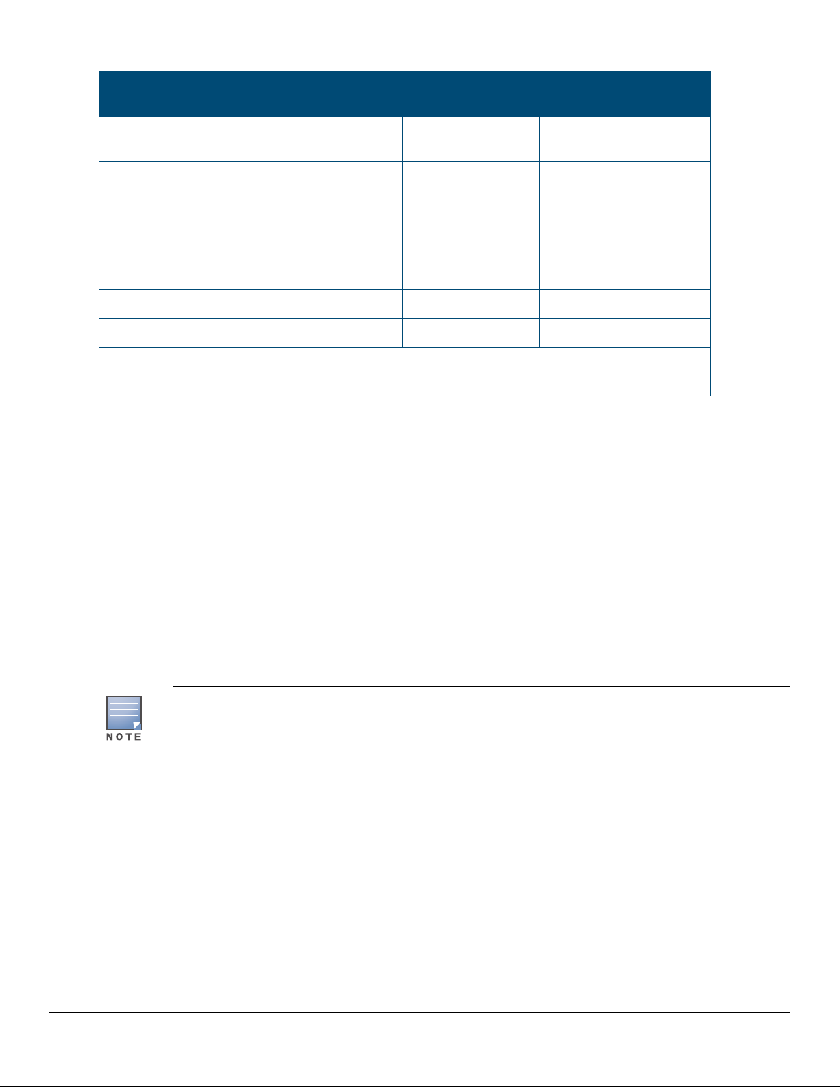
Table 17: Technology distance specifications (Continued)
Technology Supported cable type Multimode fiber
modal bandwidth
10GBASE-CR
(Direct Attach)
10GBASE-SR multimode fiber 160 MHz*km
10GBASE-LR single mode fiber N/A 2 - 10,000 meters
10GBASE-ER single mode fiber N/A 2 - 40,000 meters
1
For distances less than 20km, a 10dB attenuator must be used. For distances between 20km and
40km, a 5dB attenuator must be used. Attenuators can be purchased from most cable vendors.
twinaxial copper N/A (various lengths offered)
200 MHz*km
400 MHz*km
500 MHz*km
2000 MHz*km
Supported distances
2 - 26 meters
2 - 33 meters
2 - 66 meters
2 - 82 meters
2 - 300 meters
Mode conditioning patch cord
The following information applies to installations in which multimode fiber-optic cables are connected to a GigabitLX port. Multimode cable has a design characteristic called “Differential Mode Delay”, which requires the
transmission signals be “conditioned” to compensate for the cable design and thus prevent resulting transmission
errors.
Under certain circumstances, depending on the cable used and the lengths of the cable runs, an external Mode
Conditioning Patch Cord may need to be installed between the Gigabit-LX transmitting device and the multimode
network cable to provide the transmission conditioning. If you experience a high number of transmission errors on
those ports, usually CRC or FCS errors, you may need to install one of these patch cords between the fiber-optic
port in your switch and your multimode fiber-optic network cabling, at both ends of the network link.
The patch cord consists of a short length of single mode fiber cable coupled to graded-index multimode fiber cable
on the transmit side, and only multimode cable on the receive side. The section of single mode fiber is connected
in such a way that it minimizes the effects of the differential mode delay in the multimode cable.
Most of the time, if you are using good quality graded-index multimode fiber cable that adheres to
the standards listed in this appendix, there should not be a need to use mode conditioning patch
cords in your network. This is especially true if the fiber runs in your network are relatively short.
Installing the patch cord
As shown in the illustration below, connect the patch cord to the transceiver with the section of single mode fiber
plugged in to the Tx (transmit) port. Then, connect the other end of the patch cord to your network cabling patch
panel, or directly to the network multimode fiber.
If you connect the patch cord directly to the network cabling, you may need to install a female-to-female adapter to
allow the cables to be connected together.
Chapter 7 Cabling and technology information 43
Page 44

Figure 19: Example: Connecting a mode conditioning patch cord for Gigabit-LX
Tx
Rx
To network
multimode
cabling
Mode Conditioning
Patch Cord
The multimode cable in the
patch cord must match the
characteristics of your network
cable
Gigabit-LX port
Single mode section plugs into
Tx port on Gigabit-LX
Transceiver or Gigabit-LX
SFP
Make sure you purchase a patch cord that has appropriate connectors on each end, and has multimode fibers that
match the characteristics of the multimode fiber in your network. Most important, the core diameter of the
multimode patch cord must match the core diameter of the multimode cable infrastructure (either 50 or 62.5
microns).
44 Aruba 8320 Switch Installation and Getting Started Guide
Page 45

Chapter 8
Support and other resources
Accessing Hewlett Packard Enterprise support
• For live assistance, go to the Contact Hewlett Packard Enterprise Worldwide Support website:
www.hpe.com/assistance
• To access documentation and support services, go to the Hewlett Packard Enterprise Support Center website:
www.hpe.com/support/hpesc
Information to collect
• Technical support registration number (if applicable)
• Product name, model or version, and serial number
• Operating system name and version
• Firmware version
• Error messages
• Product-specific reports and logs
• Add-on products or components
• Third-party products or components
Hewlett Packard Enterprise offers support 24 hours a day, seven days a week through the use of a number of
automated electronic services. Hewlett Packard Enterprise provides up-to-date customer care, support and
warranty information at http://www.hpe.com/networking/support
authorized network reseller can provide you with assistance, both with services that they offer and with services
offered by Hewlett Packard Enterprise.
. Additionally, your Hewlett Packard Enterprise
Before calling support
To make most efficient use of the support process, you must retrieve the following information before calling your
authorized network reseller or Hewlett Packard Enterprise Support.
Information item Information location
• Product identification, including SFP/SFP+
transceivers
• Details about the switch’s status including the
software (OS) version, a copy of the switch
configuration, a copy of the switch Event Log,
and a copy of the switch status and counters
information
• Copy of your network topology map, including
network addresses assigned to the relevant
devices
The front of the switch and on labels on the SFP/
SFP+ transceivers
Switch console: show tech command
Your network records
Chapter 8 Support and other resources 45
Page 46

Accessing updates
• Some software products provide a mechanism for accessing software updates through the product interface.
Review your product documentation to identify the recommended software update method.
• To download product updates, go to either of the following:
• Hewlett Packard Enterprise Support Center's Subscription Service/Support Alerts page:
www.hpe.com/support/e-updates
• To view and update your entitlements, and to link your contracts, Care Packs, and warranties with your profile,
go to the Hewlett Packard Enterprise Support Center More Information on Access to HP Support Materials
page:
www.hpe.com/support/AccessToSupportMaterials
IMPORTANT: Access to some updates might require product entitlement when accessed through
the Hewlett Packard Enterprise Support Center. You must have a Hewlett Packard Enterprise
Passport set up with relevant entitlements.
• Software updates can be downloaded to the switch through several methods. Switch software updates are
available at http://www.hpe.com/networking/software
• For information on methods for downloading and installing software, see the Basic Operation Guide for your
switch in the HPE Information Library at www.hpe.com/support/manuals
.
.
Websites
Website Link
My Networking Support lookup tool www.hpe.com/networking/support
Hewlett Packard Enterprise manuals www.hpe.com/support/manuals
Hewlett Packard Enterprise Information Library www.hpe.com/info/enterprise/docs
Hewlett Packard Enterprise Support Center www.hpe.com/support/hpesc
Contact Hewlett Packard Enterprise Worldwide www.hpe.com/assistance
Hewlett Packard Enterprise Support Center's
Subscription Service/Support Alerts
Software Download www.hpe.com/networking/software
Customer Self Repair www.hpe.com/support/selfrepair
Insight Remote Support www.hpe.com/info/insightremotesupport/docs
Serviceguard Solutions for HP-UX www.hpe.com/info/hpux-serviceguard-docs
www.hpe.com/support/e-updates
46 Aruba 8320 Switch Installation and Getting Started Guide
Page 47

Customer self repair
Hewlett Packard Enterprise customer self repair (CSR) programs allow you to repair your product. If a CSR part
needs to be replaced, it will be shipped directly to you so that you can install it at your convenience. Some parts do
not qualify for CSR. Your Hewlett Packard Enterprise authorized service provider will determine whether a repair
can be accomplished by CSR.
For more information about CSR, contact your local service provider or go to the CSR website:
www.hpe.com/support/selfrepair
Remote support
Remote support is available with supported devices as part of your warranty, Care Pack Service, or contractual
support agreement. It provides intelligent event diagnosis, and automatic, secure submission of hardware event
notifications to Hewlett Packard Enterprise, which will initiate a fast and accurate resolution based on your
product’s service level. Hewlett Packard Enterprise strongly recommends that you register your device for remote
support.
For more information and device support details, go to the following website:
www.hpe.com/info/insightremotesupport/docs
Documentation feedback
Hewlett Packard Enterprise is committed to providing documentation that meets your needs. To help us improve
the documentation, send any errors, suggestions, or comments to DocumentationFeedback
(docsfeedback@hpe.com). When submitting your feedback, include the document title, part number, edition, and
publication date located on the front cover of the document. For online help content, include the product name,
product version, help edition, and publication date located on the legal notices page.
Chapter 8 Support and other resources 47
 Loading...