

Page 1

DIGITAL
HSG8 0 Array Controll er ACS Version 8 .2
EK-HSG80-UG. B01
Digital Equipment Corporation
Maynard, Mass achusetts
User’s Guide
Page 2

July 1998
While Digi tal Equipment Corporation believes the inf ormation included in this manual i s correct as of the date of
publicat ion , it is sub je ct to c ha nge wi thout no tice . DI GITAL m akes no r epres ent atio ns tha t the inter co nne ction of its
product s in the manner described in this document will not infringe existing or future patent rig hts, nor do the
descri ptions contained in this document imply the grant ing of licenses to make, use, or sell equipment or software
in acc ordance with the description. No responsibility is assumed for the use or reliability of firmware on equipment
not suppl ied by DIGITAL or its affil iated compani es. Possession, use, or copying of the software or firmw are
descri bed in this documenta tion is authorized only purs uant to a valid w ritten lic ense from DIGITAL, an authorized
sublicensor , or the identified licensor.
Commercia l Comp uter S oft wa re , Com puter Sof tware Doc ument at ion an d Techni ca l Da ta for Comm erci al It ems ar e
licensed to the U.S. Gover n m en t w it h D IGITAL’s stand a rd co m me rcial lice ns e and, when applicable, the rights in
DFAR 252.227 701 5, “Te chnical Data—Comm ercial Items. ”
© Digital Equipment Corporation, 1998.
Printed in U.S.A.
All rights reserved.
DIGITAL, DIGITAL UNIX, DECconnect, HSZ, StorageWorks, VMS, OpenVMS, and the DIGITAL logo are
tradema rks of Digital Equipm ent Corporatio n.
UNIX is a regist ered tradem ark in the U nited States and other countries exclusively through X/Open Company Ltd.
Windows NT is a trademar k of the Micr osoft Corpor ation. Sun is a regis tered trademark of Sun Microsystems , Inc.
Hewlett-Packard and HP–UX are registered trademarks of the Hewlett-Packard Company. IBM and AIX are
registered tradem arks of International Busine ss Machines Corporation. All other trademarks and registered
trade marks are th e pr operty of th ei r respect ive own er s.
This equipment has been tested and fo und to compl y with the limits for a Class A digital device, pursuant to Part 15
of the FCC Rules. These limits are designed to provide reasonable protection against harmful interference when the
equipment is operated in a commercial environment. This eq uipment generates, uses and can radiate radio frequency energy and, i f not installed and used in accordance with the manuals, may cause harmful interference to
radio communications. Operation of t his equipment in a resid en tial area is likely to cause harmful interference in
which case the user will be required to correct the int erference at his own expe nse. Restrictions apply to the use of
the local-connection port on this series of controllers; failure to observe these restr ictions may result in harmful
interference. Always disconne ct this port as soon as possible after completing the setup operation. Any changes or
modifications made to this equipment may void the user's authority t o operate the equipment.
Warning!
This is a Class A product. In a dom estic environment this product may cause radio interference in which case the
user may be required to take adequate measures.
Achtung!
Dieses i st ein Gerät der Funkstörgrenzwertklasse A. In Wohnbereichen können bei Betrieb dieses Gerätes Rundfunkstörungen auftreten, in welchen Fällen der Benutz er für entsprechende Gegen ma ßnahmen verantwortlich ist.
Avertissement!
Cet appareil est un appareil de Classe A. D ans un environnement ré sidentiel cet appareil peut provoquer des brouillages ra dioélectriques. Dans ce cas, il peut être de mandé à l’ utilisateur de prendre les mesures appropriées .
Page 3

Preface
Precautions . . . . . . . . . . . . . . . . . . . . . . . . . . . . . . . . . . . . . . . . . . . . . . . . . . . . . . xviii
Electrostatic Discharge Precautions . . . . . . . . . . . . . . . . . . . . . . . . . . . . . . . xviii
Component Precaution . . . . . . . . . . . . . . . . . . . . . . . . . . . . . . . . . . . . . . . . . . xix
Maintenance Port Precautions . . . . . . . . . . . . . . . . . . . . . . . . . . . . . . . . . . . . xix
Conventions . . . . . . . . . . . . . . . . . . . . . . . . . . . . . . . . . . . . . . . . . . . . . . . . . . . . . . .xx
T ypographical Conventions . . . . . . . . . . . . . . . . . . . . . . . . . . . . . . . . . . . . . . .xx
Special Notices . . . . . . . . . . . . . . . . . . . . . . . . . . . . . . . . . . . . . . . . . . . . . . . . xxi
Required Tools . . . . . . . . . . . . . . . . . . . . . . . . . . . . . . . . . . . . . . . . . . . . . . . . . . . .xxii
Related Publications. . . . . . . . . . . . . . . . . . . . . . . . . . . . . . . . . . . . . . . . . . . . . . . xxiii
Revision History. . . . . . . . . . . . . . . . . . . . . . . . . . . . . . . . . . . . . . . . . . . . . . . . . . xxiv
Chapter 1 General Descri ption
The HSG80 Array Controller Subsystem . . . . . . . . . . . . . . . . . . . . . . . . . . . . . . .1–2
Summary of HSG80 Features . . . . . . . . . . . . . . . . . . . . . . . . . . . . . . . . . . . . .1–4
The HSG80 Array Controller. . . . . . . . . . . . . . . . . . . . . . . . . . . . . . . . . . . . . . . . .1–7
Operator Control Panel . . . . . . . . . . . . . . . . . . . . . . . . . . . . . . . . . . . . . .1–13
Maintenance Port . . . . . . . . . . . . . . . . . . . . . . . . . . . . . . . . . . . . . . . . . . . . .1–14
Utilities and Exercisers. . . . . . . . . . . . . . . . . . . . . . . . . . . . . . . . . . . . . . . . .1–14
Cache Module . . . . . . . . . . . . . . . . . . . . . . . . . . . . . . . . . . . . . . . . . . . . . . . . . . .1–18
Caching Techniques . . . . . . . . . . . . . . . . . . . . . . . . . . . . . . . . . . . . . . . . . . .1–20
Fault-Tolerance for Write-Back Caching . . . . . . . . . . . . . . . . . . . . . . . . . . .1–21
External Cache Battery . . . . . . . . . . . . . . . . . . . . . . . . . . . . . . . . . . . . . . . . . . . .1–28
Charging Diagnostics . . . . . . . . . . . . . . . . . . . . . . . . . . . . . . . . . . . . . . . . . .1–29
iii
Chapter 2 Configuring an HSG80 Array Controller
Introduction . . . . . . . . . . . . . . . . . . . . . . . . . . . . . . . . . . . . . . . . . . . . . . . . . . . . . .2–2
Configuration Rules . . . . . . . . . . . . . . . . . . . . . . . . . . . . . . . . . . . . . . . . . . . .2–2
Configuring an HSG80 Array Controller. . . . . . . . . . . . . . . . . . . . . . . . . . . . . . . .2–3
Setting the PVA Module ID Switch . . . . . . . . . . . . . . . . . . . . . . . . . . . . . . . . . . . .2–6
Establishing a Local Connection to the Controller . . . . . . . . . . . . . . . . . . . . . . . .2–7
Selecting a Failover Mode . . . . . . . . . . . . . . . . . . . . . . . . . . . . . . . . . . . . . . . . . .2–10
Using Transparent Failover. . . . . . . . . . . . . . . . . . . . . . . . . . . . . . . . . . . . . .2–10
Using Multiple-Bus Failover . . . . . . . . . . . . . . . . . . . . . . . . . . . . . . . . . . . .2–11
Enabling Mirrored Write-Back Cache. . . . . . . . . . . . . . . . . . . . . . . . . . . . . . . . .2–12
Page 4

iv
Selecting a Cache Mode. . . . . . . . . . . . . . . . . . . . . . . . . . . . . . . . . . . . . . . . 2–12
Fault-Tolerance. . . . . . . . . . . . . . . . . . . . . . . . . . . . . . . . . . . . . . . . . . . . . . . 2–12
Backing up Power with a UPS . . . . . . . . . . . . . . . . . . . . . . . . . . . . . . . . . . . 2–13
Connecting the Subsystem to the Host . . . . . . . . . . . . . . . . . . . . . . . . . . . . . . . . 2–14
Connecting a Dua l-Redundant Configuration to the Host. . . . . . . . . . . . . . 2–16
Chapter 3 Creating Storagesets
Introduction . . . . . . . . . . . . . . . . . . . . . . . . . . . . . . . . . . . . . . . . . . . . . . . . . . . . . . 3–2
Planning and Configuring Storagesets . . . . . . . . . . . . . . . . . . . . . . . . . . . . . . . . . 3–4
Creating a Storageset and Device Profile . . . . . . . . . . . . . . . . . . . . . . . . . . . . . . . 3–5
Determining Storage Requirements . . . . . . . . . . . . . . . . . . . . . . . . . . . . . . . . . . . 3–7
Choosing a Storageset Type . . . . . . . . . . . . . . . . . . . . . . . . . . . . . . . . . . . . . . . . . 3–8
Using Stripesets to Increase I/O Performance . . . . . . . . . . . . . . . . . . . . . . . . 3–8
Using Mirrorsets to Ensure Av ailability. . . . . . . . . . . . . . . . . . . . . . . . . . . . 3–12
Using RAIDsets to Increase Performance and Availability. . . . . . . . . . . . . 3–15
Using Striped Mirrorsets for Highe s t Perfo rmance and Availability. . . . . . 3–17
Cloning Data for Backup. . . . . . . . . . . . . . . . . . . . . . . . . . . . . . . . . . . . . . . . . . . 3–19
Backing Up Your Subsystem Configuration . . . . . . . . . . . . . . . . . . . . . . . . . . . . 3–23
Saving Subsystem Configur ation Information to a Single Disk . . . . . . . . . 3–23
Saving Subsystem Configur ation Information to Multiple Disks . . . . . . . . 3–23
Saving Subsystem Configur ation Information to a Storagese t . . . . . . . . . . 3–24
Controller and Port Worldwide Names (Node IDs) . . . . . . . . . . . . . . . . . . . . . . 3–26
Restoring Worldwide Names (Node IDs) . . . . . . . . . . . . . . . . . . . . . . . . . . 3–26
Unit World Wide Names (LUN IDs) . . . . . . . . . . . . . . . . . . . . . . . . . . . . . . 3–27
Assigning Unit Numbers for Host Access to Storagesets . . . . . . . . . . . . . . . . . . 3–28
Assigning Unit Offsets. . . . . . . . . . . . . . . . . . . . . . . . . . . . . . . . . . . . . . . . . 3–29
Assigning Access Paths . . . . . . . . . . . . . . . . . . . . . . . . . . . . . . . . . . . . . . . . 3–30
Creating a Storageset Map . . . . . . . . . . . . . . . . . . . . . . . . . . . . . . . . . . . . . . . . . 3–32
Device PTL Addressing Convention within the Controller. . . . . . . . . . . . . 3–33
Planning Partitions . . . . . . . . . . . . . . . . . . . . . . . . . . . . . . . . . . . . . . . . . . . . . . . 3–37
Defining a Partition . . . . . . . . . . . . . . . . . . . . . . . . . . . . . . . . . . . . . . . . . . . 3–37
Guidelines for Partitioning Storagesets and Disk Drives. . . . . . . . . . . . . . . 3–38
Choosi n g Sw i tches for Sto r a ge s e ts an d Dev ic es. . . . . . . . . . . . . . . . . . . . . . . . . 3–39
Enabling Switches . . . . . . . . . . . . . . . . . . . . . . . . . . . . . . . . . . . . . . . . . . . . 3–39
Changing Switches. . . . . . . . . . . . . . . . . . . . . . . . . . . . . . . . . . . . . . . . . . . . 3–39
RAIDset Switches . . . . . . . . . . . . . . . . . . . . . . . . . . . . . . . . . . . . . . . . . . . . . . . . 3–40
Page 5

Replacement Policy . . . . . . . . . . . . . . . . . . . . . . . . . . . . . . . . . . . . . . . . . . .3–40
Reconstruction Policy . . . . . . . . . . . . . . . . . . . . . . . . . . . . . . . . . . . . . . . . . .3–40
Membership . . . . . . . . . . . . . . . . . . . . . . . . . . . . . . . . . . . . . . . . . . . . . . . . .3–41
Mirrorset Switches . . . . . . . . . . . . . . . . . . . . . . . . . . . . . . . . . . . . . . . . . . . . . . . .3–42
Replacement Policy . . . . . . . . . . . . . . . . . . . . . . . . . . . . . . . . . . . . . . . . . . .3–42
Copy Speed . . . . . . . . . . . . . . . . . . . . . . . . . . . . . . . . . . . . . . . . . . . . . . . . . .3–42
Read Source . . . . . . . . . . . . . . . . . . . . . . . . . . . . . . . . . . . . . . . . . . . . . . . . .3–43
Device Switches . . . . . . . . . . . . . . . . . . . . . . . . . . . . . . . . . . . . . . . . . . . . . . . . . .3–44
Transportability. . . . . . . . . . . . . . . . . . . . . . . . . . . . . . . . . . . . . . . . . . . . . . .3–44
Device Transfer Rate . . . . . . . . . . . . . . . . . . . . . . . . . . . . . . . . . . . . . . . . . .3–46
Initialize Switches . . . . . . . . . . . . . . . . . . . . . . . . . . . . . . . . . . . . . . . . . . . . . . . .3–47
Chunk Size . . . . . . . . . . . . . . . . . . . . . . . . . . . . . . . . . . . . . . . . . . . . . . . . . .3–47
Save Configuration . . . . . . . . . . . . . . . . . . . . . . . . . . . . . . . . . . . . . . . . . . . .3–50
Destroy/Nodestroy . . . . . . . . . . . . . . . . . . . . . . . . . . . . . . . . . . . . . . . . . . . .3–52
Unit Switches . . . . . . . . . . . . . . . . . . . . . . . . . . . . . . . . . . . . . . . . . . . . . . . . . . . .3–54
Configuring Storagesets with CLI Commands . . . . . . . . . . . . . . . . . . . . . . . . . .3–55
Adding Disk Drives . . . . . . . . . . . . . . . . . . . . . . . . . . . . . . . . . . . . . . . . . . .3–55
Configuring a Stripeset. . . . . . . . . . . . . . . . . . . . . . . . . . . . . . . . . . . . . . . . .3–55
Configuring a Mirrorset . . . . . . . . . . . . . . . . . . . . . . . . . . . . . . . . . . . . . . . .3–56
Configuring a RAIDset . . . . . . . . . . . . . . . . . . . . . . . . . . . . . . . . . . . . . . . . .3–57
Configuring a Striped Mirrorset . . . . . . . . . . . . . . . . . . . . . . . . . . . . . . . . . .3–59
Configuring a Single-Disk Unit . . . . . . . . . . . . . . . . . . . . . . . . . . . . . . . . . .3–60
Partitioning a Storageset or Disk Drive . . . . . . . . . . . . . . . . . . . . . . . . . . . .3–61
Adding a Disk Drive to the Spareset. . . . . . . . . . . . . . . . . . . . . . . . . . . . . . .3–63
Removing a Disk Drive from the Spareset . . . . . . . . . . . . . . . . . . . . . . . . . .3–64
Enabling Autospare. . . . . . . . . . . . . . . . . . . . . . . . . . . . . . . . . . . . . . . . . . . .3–65
Deleting a Storageset . . . . . . . . . . . . . . . . . . . . . . . . . . . . . . . . . . . . . . . . . .3–65
Changing Switches for a Storageset or Device. . . . . . . . . . . . . . . . . . . . . . .3–66
Configuring with the Command Console LUN . . . . . . . . . . . . . . . . . . . . . . . . . .3–68
Enabling and Disabling the CCL . . . . . . . . . . . . . . . . . . . . . . . . . . . . . . . . .3–68
Finding the CCL Location . . . . . . . . . . . . . . . . . . . . . . . . . . . . . . . . . . . . . .3–69
Multiple-Port and Multiple-Host Use. . . . . . . . . . . . . . . . . . . . . . . . . . . . . .3–69
Tro ubleshooting with the CCL. . . . . . . . . . . . . . . . . . . . . . . . . . . . . . . . . . .3–70
Adding Storage Units: Where Is the CCL? . . . . . . . . . . . . . . . . . . . . . . . . .3–70
Moving Storagesets . . . . . . . . . . . . . . . . . . . . . . . . . . . . . . . . . . . . . . . . . . . . . . .3–71
v
Page 6

vi
Chapter 4 Troubleshooting
Maintenance Features . . . . . . . . . . . . . . . . . . . . . . . . . . . . . . . . . . . . . . . . . . 4–1
Tro ubleshooting Checklist . . . . . . . . . . . . . . . . . . . . . . . . . . . . . . . . . . . . . . . . . . 4–2
Troubleshooting Table. . . . . . . . . . . . . . . . . . . . . . . . . . . . . . . . . . . . . . . . . . . . . . 4–4
Significant Event Reporting . . . . . . . . . . . . . . . . . . . . . . . . . . . . . . . . . . . . . . . . 4–14
Events that cause controller termination . . . . . . . . . . . . . . . . . . . . . . . . . . . 4–14
Events that do not cause controller operation to terminate . . . . . . . . . . . . . 4–15
Fault Management Utility . . . . . . . . . . . . . . . . . . . . . . . . . . . . . . . . . . . . . . 4–17
Displaying Failure Entries . . . . . . . . . . . . . . . . . . . . . . . . . . . . . . . . . . . . . . 4–17
Translating Event Codes . . . . . . . . . . . . . . . . . . . . . . . . . . . . . . . . . . . . . . . 4–18
Controlling the Display of Significant Events and Failures. . . . . . . . . . . . . 4–20
Using VTDPY to Check for Communication Problems . . . . . . . . . . . . . . . . . . . 4–23
Checking Controller-to-Host Communications . . . . . . . . . . . . . . . . . . . . 4–24
Checking Controller-to-Device Communications . . . . . . . . . . . . . . . . . . . . 4–24
Checking Unit Status and I/O Activity . . . . . . . . . . . . . . . . . . . . . . . . . . . . 4–29
Checking Fibre Channel Link Errors . . . . . . . . . . . . . . . . . . . . . . . . . . . . . . 4–31
Checking for Disk-Drive Problems. . . . . . . . . . . . . . . . . . . . . . . . . . . . . . . . . . . 4–36
Finding a Disk Drive in the Subsystem . . . . . . . . . . . . . . . . . . . . . . . . . . . . 4–36
T esting the Read Capability of a Disk Drive . . . . . . . . . . . . . . . . . . . . . . . . 4–36
T esting the Read and Write Capabilities of a Disk Drive . . . . . . . . . . . . . . 4–37
DILX Error Codes . . . . . . . . . . . . . . . . . . . . . . . . . . . . . . . . . . . . . . . . . . . . 4–40
Running the Controller’s Diagnostic Test . . . . . . . . . . . . . . . . . . . . . . . . . . . . . 4–41
Chapter 5 Replacement Procedures
Replacing Modules in a Single Controller Configuration. . . . . . . . . . . . . . . . . . . 5–2
Replacing the Controller and Cache Module in a Single Controller
Configuration . . . . . . . . . . . . . . . . . . . . . . . . . . . . . . . . . . . . . . . . . . . . . . . . . 5–2
Replacing the Controller in a Single Controller Configuration. . . . . . . . . . . 5–3
Replacing the Cache Module in a Single Controller Configuration . . . . . . . 5–6
Replacing Modul es in a Dual-Redundant Contr oller Configuration. . . . . . . . . . . 5–8
Replacing a Con troller and Cache Module in a Dual-Redundant Controlle r
Configuration . . . . . . . . . . . . . . . . . . . . . . . . . . . . . . . . . . . . . . . . . . . . . . . . . 5–9
Replacing a Con troller in a Dual-Redundant Controller Configuration . . . 5–15
Replacing a Cache Module in a Dual-Redundant Controller
Configuration . . . . . . . . . . . . . . . . . . . . . . . . . . . . . . . . . . . . . . . . . . . . . . . 5–21
Page 7

vii
Replacing the External Cache Battery St o rage
Building Block . . . . . . . . . . . . . . . . . . . . . . . . . . . . . . . . . . . . . . . . . . . . . . . . . .5–27
Replacing the External Cache Batte r y St orage Building Block
With Cabinet Powered On . . . . . . . . . . . . . . . . . . . . . . . . . . . . . . . . . . . . . .5–28
Replacing the External Cache Batte r y St orage Building Block
With Cabinet Powered Off . . . . . . . . . . . . . . . . . . . . . . . . . . . . . . . . . . . . . .5–29
Replacing the GLM . . . . . . . . . . . . . . . . . . . . . . . . . . . . . . . . . . . . . . . . . . . . . . .5–32
Replacing a PVA Module. . . . . . . . . . . . . . . . . . . . . . . . . . . . . . . . . . . . . . . . . . .5–34
Replacing the PVA in the Master Enclosure (ID 0) . . . . . . . . . . . . . . . . . . .5–34
Replacing the PVA in the First Expans ion (ID 2) or Second
Expansion Enclosure (ID 3) . . . . . . . . . . . . . . . . . . . . . . . . . . . . . . . . . . . . .5–36
Replacing an I/O Module. . . . . . . . . . . . . . . . . . . . . . . . . . . . . . . . . . . . . . . . . . .5–39
Replacing DIMMs . . . . . . . . . . . . . . . . . . . . . . . . . . . . . . . . . . . . . . . . . . . . . . . .5–42
Removing DIMMs . . . . . . . . . . . . . . . . . . . . . . . . . . . . . . . . . . . . . . . . . . . .5–43
Installing DIMMs . . . . . . . . . . . . . . . . . . . . . . . . . . . . . . . . . . . . . . . . . . . . .5–44
Replacing a Fibre Cable or Hub. . . . . . . . . . . . . . . . . . . . . . . . . . . . . . . . . . . . . .5–45
Replacing a PCMCIA Card . . . . . . . . . . . . . . . . . . . . . . . . . . . . . . . . . . . . . . . . .5–46
Replacing a Failed Storageset Member . . . . . . . . . . . . . . . . . . . . . . . . . . . . . . . .5–47
Removing a Failed RAIDset or Mirrorset Member . . . . . . . . . . . . . . . . . . .5–47
Installing the New Member . . . . . . . . . . . . . . . . . . . . . . . . . . . . . . . . . . . . .5–47
Shutting Down the Subsystem . . . . . . . . . . . . . . . . . . . . . . . . . . . . . . . . . . . . . . .5–48
Disabling and Enabling the External Cache Batteries . . . . . . . . . . . . . . . . .5–48
Restarting the Subsystem . . . . . . . . . . . . . . . . . . . . . . . . . . . . . . . . . . . . . . . . . . .5–50
Chapter 6 Upgrading the Su bsy stem
Upgrading Controller Software . . . . . . . . . . . . . . . . . . . . . . . . . . . . . . . . . . . . . . .6–2
Installing a New Program Card. . . . . . . . . . . . . . . . . . . . . . . . . . . . . . . . . . . .6–2
Downloading New Software. . . . . . . . . . . . . . . . . . . . . . . . . . . . . . . . . . . . . .6–3
Using CLCP to Install, Delete, and List Software Patches. . . . . . . . . . . . . . .6–6
Upgrading Firmware on a Device . . . . . . . . . . . . . . . . . . . . . . . . . . . . . . . . . . . .6–11
HSUTIL Messages . . . . . . . . . . . . . . . . . . . . . . . . . . . . . . . . . . . . . . . . . . . .6–14
Upgrading to a Dual-Redundant Controller Configuration . . . . . . . . . . . . . . . . .6–16
Installi ng a Ne w Controller, Cache Module, and ECB. . . . . . . . . . . . . . . . .6–16
Upgrading Cache Memory. . . . . . . . . . . . . . . . . . . . . . . . . . . . . . . . . . . . . . . . . .6–20
Page 8

viii
Appendix A System Profiles
Device Profile . . . . . . . . . . . . . . . . . . . . . . . . . . . . . . . . . . . . . . . . . . . . . . . . . . . .A–2
Storageset Profile . . . . . . . . . . . . . . . . . . . . . . . . . . . . . . . . . . . . . . . . . . . . . . . . .A–3
Enclosure Template . . . . . . . . . . . . . . . . . . . . . . . . . . . . . . . . . . . . . . . . . . . . . . . .A–4
Appendix B CLI Commands
CLI Overview . . . . . . . . . . . . . . . . . . . . . . . . . . . . . . . . . . . . . . . . . . . . . . . . . . . .B–2
Using the CLI. . . . . . . . . . . . . . . . . . . . . . . . . . . . . . . . . . . . . . . . . . . . . . . . .B–2
Command Overview . . . . . . . . . . . . . . . . . . . . . . . . . . . . . . . . . . . . . . . . . . .B–2
Getting Help. . . . . . . . . . . . . . . . . . . . . . . . . . . . . . . . . . . . . . . . . . . . . . . . . .B–3
Entering CLI Commands . . . . . . . . . . . . . . . . . . . . . . . . . . . . . . . . . . . . . . . .B–3
Changing the CLI Prompt . . . . . . . . . . . . . . . . . . . . . . . . . . . . . . . . . . . . . . .B–4
Command Syntax. . . . . . . . . . . . . . . . . . . . . . . . . . . . . . . . . . . . . . . . . . . . . .B–5
ADD CONNECTIONS . . . . . . . . . . . . . . . . . . . . . . . . . . . . . . . . . . . . . . . . . . . .B–7
ADD DISK . . . . . . . . . . . . . . . . . . . . . . . . . . . . . . . . . . . . . . . . . . . . . . . . . . . . .B–11
ADD MIRRORSET . . . . . . . . . . . . . . . . . . . . . . . . . . . . . . . . . . . . . . . . . . . . . .B–15
ADD RAIDSET . . . . . . . . . . . . . . . . . . . . . . . . . . . . . . . . . . . . . . . . . . . . . . . . .B–19
ADD SPARESET . . . . . . . . . . . . . . . . . . . . . . . . . . . . . . . . . . . . . . . . . . . . . . . .B–23
ADD STRIPESET . . . . . . . . . . . . . . . . . . . . . . . . . . . . . . . . . . . . . . . . . . . . . . .B–25
ADD UNIT . . . . . . . . . . . . . . . . . . . . . . . . . . . . . . . . . . . . . . . . . . . . . . . . . . . . .B–27
CLEAR_ERRORS CLI . . . . . . . . . . . . . . . . . . . . . . . . . . . . . . . . . . . . . . . . . . .B–35
CLEAR_ERRORS controller INVALID_CACHE . . . . . . . . . . . . . . . . . . . . . .B–37
CLEAR_ERRORS device-name UNKNOWN . . . . . . . . . . . . . . . . . . . . . . . . .B–39
CLEAR_ERRO RS u ni t-num be r LOST_DATA . . . . . . . . . . . . . . . . . . . . . . . . .B–41
CLEAR_ERRORS unit-number UNWRITEABLE_DATA . . . . . . . . . . . . . . . .B–43
CONFIGURATION RESET . . . . . . . . . . . . . . . . . . . . . . . . . . . . . . . . . . . . . . .B–45
CONFIGURATION RESTORE . . . . . . . . . . . . . . . . . . . . . . . . . . . . . . . . . . . . .B–47
CONFIGURATION SAVE . . . . . . . . . . . . . . . . . . . . . . . . . . . . . . . . . . . . . . . . .B–49
CREATE_PARTITION . . . . . . . . . . . . . . . . . . . . . . . . . . . . . . . . . . . . . . . . . . .B–51
DELETE connections . . . . . . . . . . . . . . . . . . . . . . . . . . . . . . . . . . . . . . . . . . . . .B–55
DELETE container-name . . . . . . . . . . . . . . . . . . . . . . . . . . . . . . . . . . . . . . . . .B–57
DELETE FAILEDSET . . . . . . . . . . . . . . . . . . . . . . . . . . . . . . . . . . . . . . . . . . . .B–59
DELETE SPARESET . . . . . . . . . . . . . . . . . . . . . . . . . . . . . . . . . . . . . . . . . . . . .B–61
DELETE unit-number . . . . . . . . . . . . . . . . . . . . . . . . . . . . . . . . . . . . . . . . . . . .B–63
DESTROY_PARTITION . . . . . . . . . . . . . . . . . . . . . . . . . . . . . . . . . . . . . . . . . .B–65
DIRECTORY . . . . . . . . . . . . . . . . . . . . . . . . . . . . . . . . . . . . . . . . . . . . . . . . . . . B–67
Page 9

HELP . . . . . . . . . . . . . . . . . . . . . . . . . . . . . . . . . . . . . . . . . . . . . . . . . . . . . . . B–69
INITIALIZE . . . . . . . . . . . . . . . . . . . . . . . . . . . . . . . . . . . . . . . . . . . . . . . . . . . B–71
LOCATE . . . . . . . . . . . . . . . . . . . . . . . . . . . . . . . . . . . . . . . . . . . . . . . . . . . . . . B–77
MIRROR . . . . . . . . . . . . . . . . . . . . . . . . . . . . . . . . . . . . . . . . . . . . . . . . . . . . . . B–79
POWEROFF . . . . . . . . . . . . . . . . . . . . . . . . . . . . . . . . . . . . . . . . . . . . . . . . . . . B–83
REDUCE . . . . . . . . . . . . . . . . . . . . . . . . . . . . . . . . . . . . . . . . . . . . . . . . . . . . . . B–85
RENAME . . . . . . . . . . . . . . . . . . . . . . . . . . . . . . . . . . . . . . . . . . . . . . . . . . . . . B–89
RESTART controller . . . . . . . . . . . . . . . . . . . . . . . . . . . . . . . . . . . . . . . . . . . . . B–91
RETRY_ERRORS UNWRITEABLE_DATA . . . . . . . . . . . . . . . . . . . . . . . . . B–93
RUN . . . . . . . . . . . . . . . . . . . . . . . . . . . . . . . . . . . . . . . . . . . . . . . . . . . . . . . . . B–95
SELFTEST controller . . . . . . . . . . . . . . . . . . . . . . . . . . . . . . . . . . . . . . . . . . . . B–99
SET connection-name . . . . . . . . . . . . . . . . . . . . . . . . . . . . . . . . . . . . . . . . . . . B–101
SET controller . . . . . . . . . . . . . . . . . . . . . . . . . . . . . . . . . . . . . . . . . . . . . . . . B–103
SET device-name . . . . . . . . . . . . . . . . . . . . . . . . . . . . . . . . . . . . . . . . . . . . . . B–111
SET EMU . . . . . . . . . . . . . . . . . . . . . . . . . . . . . . . . . . . . . . . . . . . . . . . . . . . . B–113
SET FAILEDSET . . . . . . . . . . . . . . . . . . . . . . . . . . . . . . . . . . . . . . . . . . . . . . B–117
SET FAILOVER . . . . . . . . . . . . . . . . . . . . . . . . . . . . . . . . . . . . . . . . . . . . . . . B–119
SET mirrorset-name . . . . . . . . . . . . . . . . . . . . . . . . . . . . . . . . . . . . . . . . . . . . B–121
SET MULTIBUS_FAILOVER . . . . . . . . . . . . . . . . . . . . . . . . . . . . . . . . . . . . B–127
SET NOF AILOVER . . . . . . . . . . . . . . . . . . . . . . . . . . . . . . . . . . . . . . . . . . . . B–129
SET NOMULTIBUS_FAILOVER . . . . . . . . . . . . . . . . . . . . . . . . . . . . . . . . . B–131
SET RAIDset-name . . . . . . . . . . . . . . . . . . . . . . . . . . . . . . . . . . . . . . . . . . . . B–133
SET unit-number . . . . . . . . . . . . . . . . . . . . . . . . . . . . . . . . . . . . . . . . . . . . . . . B–137
SHOW . . . . . . . . . . . . . . . . . . . . . . . . . . . . . . . . . . . . . . . . . . . . . . . . . . . . . . . B–143
SHUTDOWN controller . . . . . . . . . . . . . . . . . . . . . . . . . . . . . . . . . . . . . . . . . B–149
UNMIRROR . . . . . . . . . . . . . . . . . . . . . . . . . . . . . . . . . . . . . . . . . . . . . . . . . . B–151
ix
Appendix C LED Codes
Operator Control Panel LED Codes. . . . . . . . . . . . . . . . . . . . . . . . . . . . . . . . . . . C–2
Solid OCP Patterns . . . . . . . . . . . . . . . . . . . . . . . . . . . . . . . . . . . . . . . . . . . . C–3
Flashing OCP Patterns . . . . . . . . . . . . . . . . . . . . . . . . . . . . . . . . . . . . . . . . . C–8
Appendix D Event Reporting: Templates and Codes
Passthrough Device Reset Event Sense Data Response. . . . . . . . . . . . . . . . . . . . D–2
Last Failure Event Sense Data Response . . . . . . . . . . . . . . . . . . . . . . . . . . . D–3
Multiple-Bus Failover Event Sense Data Response . . . . . . . . . . . . . . . . . . . D–5
Page 10

x
Failover Event Sense Data Respons e. . . . . . . . . . . . . . . . . . . . . . . . . . . . . . .D–6
Nonvolatile Parameter Memory Component Event Sense
Data Response . . . . . . . . . . . . . . . . . . . . . . . . . . . . . . . . . . . . . . . . . . . . . . . .D–8
Backup Batte r y F ailure Event Sense Data Response. . . . . . . . . . . . . . . . . . .D–9
Subsystem Buil t-In Self Tes t Failure Event Sense Data Response . . . . . . .D–10
Memory System Failure Event Sense Data Response . . . . . . . . . . . . . . . . .D–12
Device Serv ices Non-Transfer Error Event Sense Data Response . . . . . . .D–13
Disk Trans f er Error Event Sense Data Response. . . . . . . . . . . . . . . . . . . . .D–14
Instance Codes. . . . . . . . . . . . . . . . . . . . . . . . . . . . . . . . . . . . . . . . . . . . . . . . . . .D–16
Instance Code Structure . . . . . . . . . . . . . . . . . . . . . . . . . . . . . . . . . . . . . . . .D–16
Instance Codes and FMU. . . . . . . . . . . . . . . . . . . . . . . . . . . . . . . . . . . . . . .D–16
Last Failure Codes. . . . . . . . . . . . . . . . . . . . . . . . . . . . . . . . . . . . . . . . . . . . . . . .D–36
Last Failure Code Structure . . . . . . . . . . . . . . . . . . . . . . . . . . . . . . . . . . . . .D–36
Last Failure Codes and FMU . . . . . . . . . . . . . . . . . . . . . . . . . . . . . . . . . . . .D–36
Recommended Repair Action Codes . . . . . . . . . . . . . . . . . . . . . . . . . . . . . . . . .D–77
Component Identifier Codes . . . . . . . . . . . . . . . . . . . . . . . . . . . . . . . . . . . . . . . .D–82
Event Threshold Codes . . . . . . . . . . . . . . . . . . . . . . . . . . . . . . . . . . . . . . . . . . . .D–84
ASC/ASCQ Codes . . . . . . . . . . . . . . . . . . . . . . . . . . . . . . . . . . . . . . . . . . . . . . .D–85
Appendix E Controller Specifications
Physical and Electrical Specifications for the Controller . . . . . . . . . . . . . . . . . . . E–2
Environmental Specifications . . . . . . . . . . . . . . . . . . . . . . . . . . . . . . . . . . . . . . . . E–3
Glossary
Index
Page 11

Figures
xi
The HSG80 Subsystem . . . . . . . . . . . . . . . . . . . . . . . . . . . . . . . . . . . . . . . . . . . . .1–3
A Host and Its Storage Subsystem. . . . . . . . . . . . . . . . . . . . . . . . . . . . . . . . . . . . .1–7
HSG80 Array Controller–Fibre Channel Copper Cabling. . . . . . . . . . . . . . . . . . .1–8
Optional Maintenance Port Cable for a Terminal Connection. . . . . . . . . . . . . . .1–10
HSG80 Array Controller–Fibre Channel Optical Cabling. . . . . . . . . . . . . . . . . .1–11
Location of Cont rollers and Cache Modules . . . . . . . . . . . . . . . . . . . . . . . . . . .1–13
HSG80 Controller Operator Control Panel (OCP). . . . . . . . . . . . . . . . . . . . . . . .1–14
Cache Module . . . . . . . . . . . . . . . . . . . . . . . . . . . . . . . . . . . . . . . . . . . . . . . . . . .1–19
ECB for Dual-Redundant Configurat ions . . . . . . . . . . . . . . . . . . . . . . . . . . . . . .1–28
SCSI Target ID Numbers on the Controller Device Bus and PVA Settings
in an Extended Subsytem. . . . . . . . . . . . . . . . . . . . . . . . . . . . . . . . . . . . . . . . . . . .2–6
Terminal to Local- Connection Port Connection . . . . . . . . . . . . . . . . . . . . . . . . . .2–7
“This Controller” and “Other Controller” . . . . . . . . . . . . . . . . . . . . . . . . . . . . . . .2–9
Cabling for Sing le Configuration with Fibre Channel Copper Support . . . . . . .2–14
Cabling for Sing le Configuration with Fibre Channel Optical S upport . . . . . . .2–15
Cabling for Dual-Re dundant Configu ration with Two Hubs using
Fibre Channel Copper Support . . . . . . . . . . . . . . . . . . . . . . . . . . . . . . . . . . . . . .2–17
Cabling for Dual-Re dundant Configu ration with Two Hubs using
Fibre Channel Optical Support . . . . . . . . . . . . . . . . . . . . . . . . . . . . . . . . . . . . . .2–18
Cabling for Dual-Re dundant Configu ration with One Hub using
Fibre Channel Copper Support . . . . . . . . . . . . . . . . . . . . . . . . . . . . . . . . . . . . . .2–20
Cabling for Dual-Re dundant Configu ration with One Hub using
Fibre Channel Optical Support . . . . . . . . . . . . . . . . . . . . . . . . . . . . . . . . . . . . . .2–21
Units Created from Storagesets, Partitions, and Drives . . . . . . . . . . . . . . . . . . . . .3–3
A Typical Storageset Profile . . . . . . . . . . . . . . . . . . . . . . . . . . . . . . . . . . . . . . . . .3–6
Striping Lets Several Disk Drives Participate in Each I/O Request. . . . . . . . . . . .3–9
Distribute Members across Ports . . . . . . . . . . . . . . . . . . . . . . . . . . . . . . . . . . . . .3–11
Mirrorsets Maintain Two Copies of the Same Data. . . . . . . . . . . . . . . . . . . . . . .3–12
First Mirrorset Members on Different Buses . . . . . . . . . . . . . . . . . . . . . . . . . . . .3–13
Page 12

xii
Parity Ensures Availability; Striping Provides Good Performance. . . . . . . . . . . 3–15
Striping and Mirroring in the Same Storageset. . . . . . . . . . . . . . . . . . . . . . . . . . 3–17
CLONE Steps for Duplicating Unit Members . . . . . . . . . . . . . . . . . . . . . . . . . . 3–20
Controller Port ID and Unit Numbers in Transparent Failover Mode . . . . . . . . 3–28
Controller Port ID Numbers and Unit Numbers in Mulitple Bus Failover
Mode . . . . . . . . . . . . . . . . . . . . . . . . . . . . . . . . . . . . . . . . . . . . . . . . . . . . . . . . . . 3–29
LUN Presentation Using Unit Offset on a Per-Host Basis . . . . . . . . . . . . . . . . . 3–30
Storageset Map . . . . . . . . . . . . . . . . . . . . . . . . . . . . . . . . . . . . . . . . . . . . . . . . . . 3–32
PTL Naming Convention . . . . . . . . . . . . . . . . . . . . . . . . . . . . . . . . . . . . . . . . . . 3–34
PTL Addressing in a Configuration . . . . . . . . . . . . . . . . . . . . . . . . . . . . . . . . . . 3–35
Locating Devices using PTLs . . . . . . . . . . . . . . . . . . . . . . . . . . . . . . . . . . . . . . . 3–36
Partitioning a Single-Disk Unit. . . . . . . . . . . . . . . . . . . . . . . . . . . . . . . . . . . . . . 3–37
Chunk Size Larger than the Request Size. . . . . . . . . . . . . . . . . . . . . . . . . . . . . . 3–48
Chunk Size Smaller than the Request Size. . . . . . . . . . . . . . . . . . . . . . . . . . . . . 3–49
Moving a Storageset from one Subsystem to Another . . . . . . . . . . . . . . . . . . . . 3–71
Troubleshooting: Host Canno t Acc es s Unit . . . . . . . . . . . . . . . . . . . . . . . . . . . . 4–12
Xfer Rate Region of the Default Display . . . . . . . . . . . . . . . . . . . . . . . . . . . . . . 4–24
Regions on the Device Display . . . . . . . . . . . . . . . . . . . . . . . . . . . . . . . . . . . . . . 4–25
Unit Status on the Cache Display . . . . . . . . . . . . . . . . . . . . . . . . . . . . . . . . . . . . 4–29
Fibre Channel Host Status Display . . . . . . . . . . . . . . . . . . . . . . . . . . . . . . . . . . . 4–32
Single Controller Configuration . . . . . . . . . . . . . . . . . . . . . . . . . . . . . . . . . . . . . . 5–2
Dual-Redundant Controller Configuration . . . . . . . . . . . . . . . . . . . . . . . . . . . . . . 5–8
Single-Battery ECB SSB Configuration . . . . . . . . . . . . . . . . . . . . . . . . . . . . . . . 5–27
Dual-battery ECB SBB Configuration . . . . . . . . . . . . . . . . . . . . . . . . . . . . . . . . 5–27
Location of GLMs in Controller . . . . . . . . . . . . . . . . . . . . . . . . . . . . . . . . . . . . . 5–32
I/O Module Locations in a BA370 Enclosure. . . . . . . . . . . . . . . . . . . . . . . . . . . 5–39
Cache-Module Memory Configurations . . . . . . . . . . . . . . . . . . . . . . . . . . . . . . . 5–42
Installing a DIMM. . . . . . . . . . . . . . . . . . . . . . . . . . . . . . . . . . . . . . . . . . . . . . . . 5–44
Battery Disable Switch . . . . . . . . . . . . . . . . . . . . . . . . . . . . . . . . . . . . . . . . . . . . 5–49
Location of Write-Protection Switch . . . . . . . . . . . . . . . . . . . . . . . . . . . . . . . . . . 6–4
Upgrading Device Firmware . . . . . . . . . . . . . . . . . . . . . . . . . . . . . . . . . . . . . . . . 6–11
Pass-through Device Reset Event Sense Data Response Format . . . . . . . . . . . . .D–2
T emplate 01 - Last Failure Event Sense Data Response Format. . . . . . . . . . . . . .D–4
Template 04 - Mu lt ip l e -Bus Failove r Eve n t Se n se Da ta Respon se Format . . . . .D–5
Page 13

xiii
Template 05 - Failover Event Sense Data Response Format . . . . . . . . . . . . . . . . D–7
Template 11 - Nonvolatile Parameter Memory Component Event Sense Data
Response Form at . . . . . . . . . . . . . . . . . . . . . . . . . . . . . . . . . . . . . . . . . . . . . . . . . D–8
Template 12 - Backup Battery Failure Event Sense Data Response Format. . . . D–9
Template 13 - Subsystem Built-In Self Test Failure Event Sense Data
Response Form at . . . . . . . . . . . . . . . . . . . . . . . . . . . . . . . . . . . . . . . . . . . . . . . . D–11
Template 14 - Memory System Failure Event Sense Data Response Format . . D–12
Temp l at e 41 - Devi ce Servic es N o n- Tra ns f er Er ro r Event Sense Da ta
Response Form at . . . . . . . . . . . . . . . . . . . . . . . . . . . . . . . . . . . . . . . . . . . . . . . . D–13
Template 51 - Disk Transfer Error Event Sense Data Response Format. . . . . . D–15
Structure of an Instance Code . . . . . . . . . . . . . . . . . . . . . . . . . . . . . . . . . . . . . . D–16
Instance Code Format . . . . . . . . . . . . . . . . . . . . . . . . . . . . . . . . . . . . . . . . . . . . D–16
Structure of a Last Failure Code . . . . . . . . . . . . . . . . . . . . . . . . . . . . . . . . . . . . D–36
Last Failure Code Format. . . . . . . . . . . . . . . . . . . . . . . . . . . . . . . . . . . . . . . . . . D–36
Page 14

Page 15

Tables
xv
Key to Figure 1–1 The HSG80 Subsystem . . . . . . . . . . . . . . . . . . .1–3
Controller Features . . . . . . . . . . . . . . . . . . . . . . . . . . . . . . . . . . . . . .1–4
Key to Figure 1–3 HSG80 Array Controller–Fibre Channel
Copper Cabling . . . . . . . . . . . . . . . . . . . . . . . . . . . . . . . . . . . . . . . . .1–9
Key to Figure 1–4: Opti onal Maintenance Port Cable for a
T erminal Connection. . . . . . . . . . . . . . . . . . . . . . . . . . . . . . . . . . . . .1–10
Key to Figure 1–4 HSG80 Array Controller–Fibre Channel
Optical cabling . . . . . . . . . . . . . . . . . . . . . . . . . . . . . . . . . . . . . . . . .1–11
Cache Module Memory Con f igurations. . . . . . . . . . . . . . . . . . . . . .1–18
Cache Policies and Cache Module Status . . . . . . . . . . . . . . . . . . . .1–22
Cache Policies Resulting and ECB Status . . . . . . . . . . . . . . . . . . . .1–24
ECB Capacity Based on Memory Size. . . . . . . . . . . . . . . . . . . . . . .1–29
Key to Figure 2–4 Cabling for S ingle Configur ation (copper). . . . .2–14
Key to Figure 2–5 Cabling for S ingle Configuration (optical). . . . .2–15
Key to Figure 2–6 Cabling for Dual-Redundant Conf iguration
with Two Hubs (copper) . . . . . . . . . . . . . . . . . . . . . . . . . . . . . . . . .2–17
Key to Figure 2–7 Cabling for Dual-Redundant Conf iguration
with Two Hubs (optical) . . . . . . . . . . . . . . . . . . . . . . . . . . . . . . . . . .2–18
Key to Figure 2–8 Cabling for Dual-Redundant Conf iguration
with One Hub (copper) . . . . . . . . . . . . . . . . . . . . . . . . . . . . . . . . . .2–20
Key to Figure 2–9 Cabling for Dual-Redundant Conf iguration
with One Hub (optical) . . . . . . . . . . . . . . . . . . . . . . . . . . . . . . . . . . .2–21
Controller Limitations for RAIDsets . . . . . . . . . . . . . . . . . . . . . . . . .3–3
A Comparison of Different Kinds of Storagesets. . . . . . . . . . . . . . . .3–8
Maximum Chunk Sizes for a RAIDs et . . . . . . . . . . . . . . . . . . . . . .3–50
Unit Switches . . . . . . . . . . . . . . . . . . . . . . . . . . . . . . . . . . . . . . . . . .3–54
Troubleshooting Table . . . . . . . . . . . . . . . . . . . . . . . . . . . . . . . . . . . .4–4
Event-Code Types. . . . . . . . . . . . . . . . . . . . . . . . . . . . . . . . . . . . . . .4–19
FMU SET Commands . . . . . . . . . . . . . . . . . . . . . . . . . . . . . . . . . . .4–20
Page 16

xvi
VTDPY Key Sequences and Commands. . . . . . . . . . . . . . . . . . . . . 4–23
Device Map Columns . . . . . . . . . . . . . . . . . . . . . . . . . . . . . . . . . . . 4–25
Device Status Columns . . . . . . . . . . . . . . . . . . . . . . . . . . . . . . . . . . 4–26
Device-Port Status Columns . . . . . . . . . . . . . . . . . . . . . . . . . . . . . . 4–28
Unit Status Columns . . . . . . . . . . . . . . . . . . . . . . . . . . . . . . . . . . . . 4–29
Fibre Channel Hos t Status Display- Known Hosts (Connections) . 4–32
Fibre Channel Host Status Display- Port Status . . . . . . . . . . . . . . . 4–33
Fibre Channel Hos t St atus Display- Link Error Counte r s . . . . . . . 4–33
Tachyon First Digit . . . . . . . . . . . . . . . . . . . . . . . . . . . . . . . . . . . . . 4–35
Tachyon Second Digi t . . . . . . . . . . . . . . . . . . . . . . . . . . . . . . . . . . . 4–35
DILX Control Sequences. . . . . . . . . . . . . . . . . . . . . . . . . . . . . . . . . 4–37
Data Patterns for Phase 1: Write Test . . . . . . . . . . . . . . . . . . . . . . . 4–38
DILX Error Codes . . . . . . . . . . . . . . . . . . . . . . . . . . . . . . . . . . . . . . 4–40
Cache Module Memory Con f igurations. . . . . . . . . . . . . . . . . . . . . . 5–42
HSUTIL Messages and Inquiries . . . . . . . . . . . . . . . . . . . . . . . . . . 6–14
Cache Module Memory Con f igurations. . . . . . . . . . . . . . . . . . . . . . 6–20
Recall and Edit Command Keys . . . . . . . . . . . . . . . . . . . . . . . . . . . .B–4
ADD UNIT Switches for Storagesets . . . . . . . . . . . . . . . . . . . . . . .B–28
POWEROFF Switch Settings. . . . . . . . . . . . . . . . . . . . . . . . . . . . . .B–84
SET controller Switches . . . . . . . . . . . . . . . . . . . . . . . . . . . . . . . .B–104
EMU Set Point Temperatures. . . . . . . . . . . . . . . . . . . . . . . . . . . . .B–114
SET unit-number Switc hes for Exi sting Containers . . . . . . . . . . .B–138
Solid OCP Patterns . . . . . . . . . . . . . . . . . . . . . . . . . . . . . . . . . . . . . .C–3
Flashing OCP Patterns . . . . . . . . . . . . . . . . . . . . . . . . . . . . . . . . . . .C–8
Instance Codes . . . . . . . . . . . . . . . . . . . . . . . . . . . . . . . . . . . . . . . .D–18
Controller Restart Codes . . . . . . . . . . . . . . . . . . . . . . . . . . . . . . . . .D–37
Last Failure Codes . . . . . . . . . . . . . . . . . . . . . . . . . . . . . . . . . . . . . .D–38
Recommended Repair Action Codes . . . . . . . . . . . . . . . . . . . . . . .D–77
Component Identifier Codes . . . . . . . . . . . . . . . . . . . . . . . . . . . . . .D–82
Event Notification/Recovery Threshold Classifications . . . . . . . . .D–84
ASC and ASCQ Codes . . . . . . . . . . . . . . . . . . . . . . . . . . . . . . . . . .D–85
Controller Specifications . . . . . . . . . . . . . . . . . . . . . . . . . . . . . . . . . . E–2
StorageWorks Environmental Specifications . . . . . . . . . . . . . . . . . . E–3
Page 17

Preface
xvii
This book describes the features of the HSG80 array controller and configuration
procedures for the controller and storagesets running Array Controller Softw are
(ACS) Version 8.2G.
This book does not con tain information about the operating envi ronments to which
the controller may be connected, nor does it co ntain detailed informa tion about
subsystem enclosures or their components. See the documentation that
accompanied these peripherals for information about them.
Page 18
xviii
Precautions
Follow these precau tions when ca rr y i ng o ut th e pro cedures in th i s
book.
Electrostatic Discharge Precautions
Static electricity collects on all nonconducting material, such as paper,
cloth, an d plastic. An ele ctrostatic dis charge (ESD) can easily damage a
controller or other subsystem component even though you may not see
or feel the discharge. Follow these precautions whenever you’re
servicing a subsystem or one of its components:
n
Always use an ESD wrist stra p when s ervicing the controlle r or
other components in the subsystem. Make sure that the strap
contacts bare skin, fits snugly, and that its grounding lead is
attached to a bus that is a verified earth ground.
n
Before touching any circuit board or component, always touch a
verif iable earth ground to disc harge any static electricity that may
be present in you r clothing.
n
Alwa y s keep circuit boards an d component s away from
nonconducting material.
n
Always keep cl othing away from circuit boards and components.
n
Always use antis tatic bags and grounding mats for storing circuit
boards or component s duri ng replacement procedures.
n
Always keep the ESD cover over the program card when the card is
in the controller. If you remove the card, put it in its ori ginal
carrying case. Never touch the conta cts or twist or bend the card
while you’re handling it.
n
Never touch the connector pins of a cable when it is attached to a
component or host.
Page 19

Component Precaution
System components referenced in this manual comply to regulatory
standards docu mented herein. Use of other components in their place
may violate country standards, negate regulatory compliance, or
invalidate the warra nty on your product.
Maintenance Port Precautions
The maintenance port gen era tes, uses, and radiates radio-frequency
energy through cables that are connected to it. This energy may
interfere wit h radio and television reception. Do not leave a cable
connected to this port when you’re not communicating with the
controller.
xix
Page 20

xx
Conventions
This book uses th e following typogr aphical conventio ns and special
notices to help you find what you’re looking for.
Typographical Conventions
Convention Meaning
ALLCAPS BOLD
ALLCAPS Command discussed within text, for exam ple:
Monospaced Screen display.
Sans seri f it a lic Command variable or numeric value that you
italic Reference to other books or publications, for
.
.
.
“this controller” The controller serving your current CLI session
“other controller” The controller in a dual-redundant pair that’s
Command syntax that mu st be ent ered exactly as
shown, for example:
SET FAILOVER COPY=OTHER_CONTROLLER
“Use the SHOW SPARESET command t o show
the contents of the spareset.”
supply, for example: SHO W RAIDset-name or
SET THIS_CONTROLLER ID=(n,n,n,n,)
example: “See the HSG80 Array Controller ACS
V8.2 Release Notes for details.”
Indicates that a portion of an example or figure
has been omitted.
through a local or remote terminal.
connected to the cont roller serving your current
CLI session.
Page 21
Special Notices
xxi
This book doesn’t contain detailed desc riptions of standard safety
procedures. However, it does contain warni ngs for procedures that
could cause personal injury and cautions for procedures that could
damage the controller or its related components . L ook for these
symbols when you’re carrying out the procedures in this book:
Warning A warning indicates th e presence of a hazard that can cause
personal injury if you do not observe the precautions in the text.
Caution A caution indicates the presence of a hazard that might
damage hardware, corrupt software, or cause a loss of data.
Tip A tip provides alternative methods or procedures that may not be
immediately obvious. A tip may also aler t cus tomers that the
controller’s behavior being discussed is different from prior software or
hardware versions.
Note A note provides additional information that’s related to the
completio n of an instruction or procedure.
Page 22
xxii
Required Tools
You wil l ne ed th e f ollowing tools to se r v ic e th e contr ol l er, cache
module, external cache battery (ECB), the Power Verification and
Addressing (PVA) module, the Gigabit Link Module (GLM), and the
I/O module:
n
A flathead screwdri v er for looseni ng and tighte ning the I/O module
retaining s crews.
n
A small phillips screwdriver for loosening and tigh tening the GLM
access do o r s cr ews .
n
An anti s tatic wrist strap .
n
An antistatic mat on which to place modules during servicing.
n
A Storage Building Block (SBB) Extractor for remo ving
StorageWorks building blocks. This tool is not required, but it will
enable you to perform more efficiently.
Page 23
Related Publications
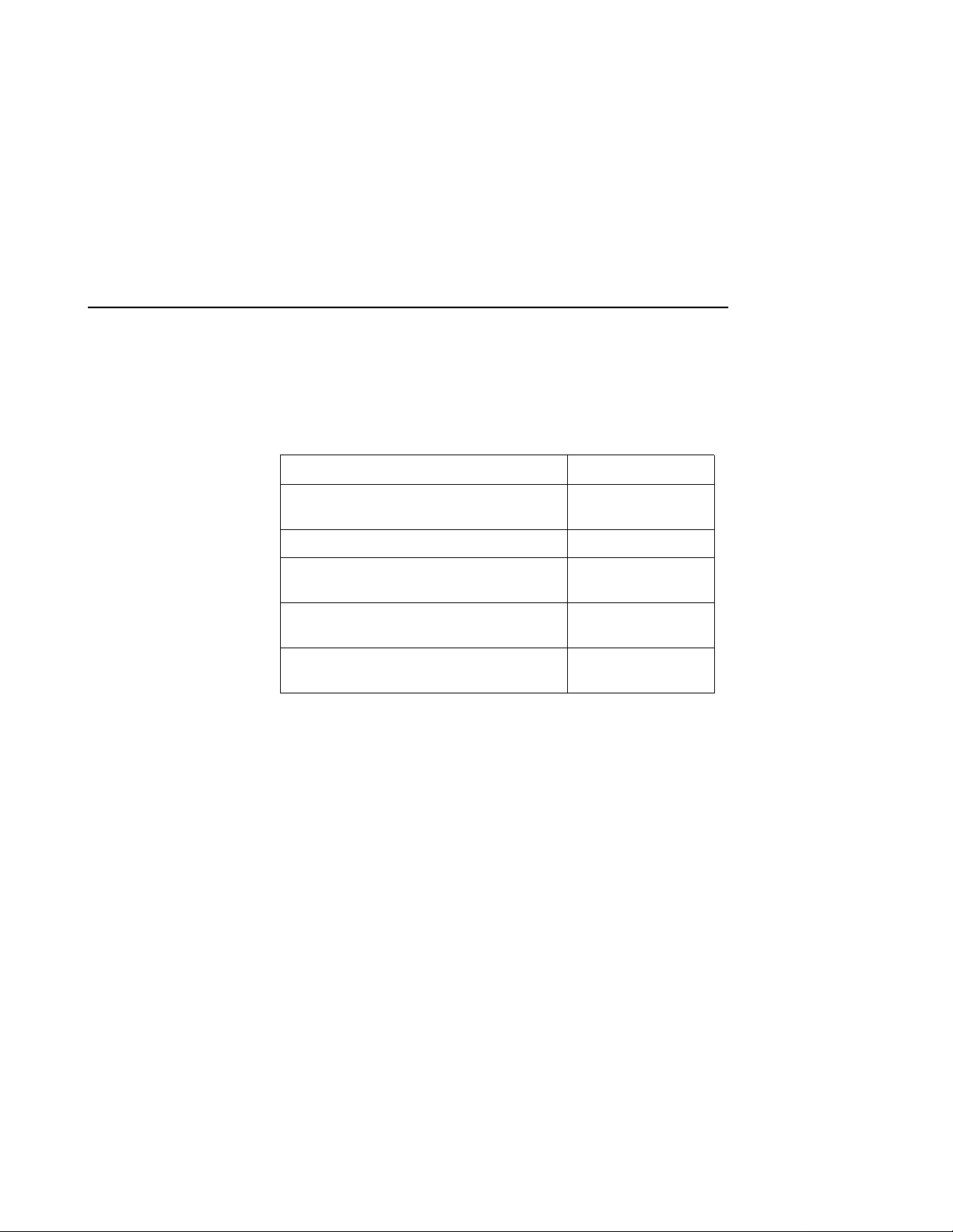
The fo ll ow in g table list s some of the do cuments th a t ar e related to th e
use of the controller, cache module, and external cache battery.
xxiii
Document Title Part Number
Fibre Ch annel Ar b it r at ed Lo op H u b
(DS-DHGGA-CA) User’s Guide
KGPSA PCI-to-Fibre Channel Host Adapter EK–KGPSA–UG
DIGITAL StorageW orks Ultra SCSI RAID
Enclosure (BA370-S eries) User’s Guide
The RAIDBOOK—A Source for RAID
Technology
DIGITAL StorageWorks HSG80 Array
Controller ACS V8.2 Release Notes
EK–DHGGA–UG
EK–BA370–UG
RAID Advisory
Board
AA–RDY8A–TE
Page 24

xxiv
Revision History
This is a rev ised document. Prev ious documents include:
EK-HSG80-UG .A01 ACS Version 8.0 January 1998
Page 25

CHAPTER 1
General Description
This chapter i llustrates and describes in general terms your subsystem and its major
components: the HSG80 array controller, its cache module, and its external cache
battery. See the Fibre Channel Arbitrated Loop Hub User’s Guide and the KGPSA
PCI-to-Fibre Channel Hos t Adapter User Guide for information about the fibre
channel arbitrated loop hub and adapter that connect the subsystem to your host.
1–1
Page 26
1–2 HSG80 User’s Gui de
The HSG80 Array Controller Subsystem
Take a few moments to familiarize yourself with the major components
of the HSG80 Array Controlle r subsys tem. Figure 1–1 shows the
components of a typical installation which includes:
n
One BA370 rack-mountable pedestal enclosure.
n
Two controllers, each supported by their own cache module.
n
T wo ex ternal cache bat ter ies (ECBs ) in one Stora ge Build ing Bl ock
(SBB), which provide backup power to the cache modules during a
primary powe r failure.
n
One environmental monitoring unit (EMU) that monitors the
subsystem’s environment, and alerts the controller of equipment
failures that could cause an abnormal environment.
n
One power verification and addressing (PVA) module that provides
a unique address to each enclosure in an ex tended subsystem.
n
Six I/O modules that in tegrate the SSB shelf with either an 8-bit
single-ended, 16-bit single-ende d, or 16-bit differ ential SCSI bus.
n
Two cache modules, which support non volatile memory and
dynamic cache policies to protect the availability of its unwritten
(write-back) data.
Page 27
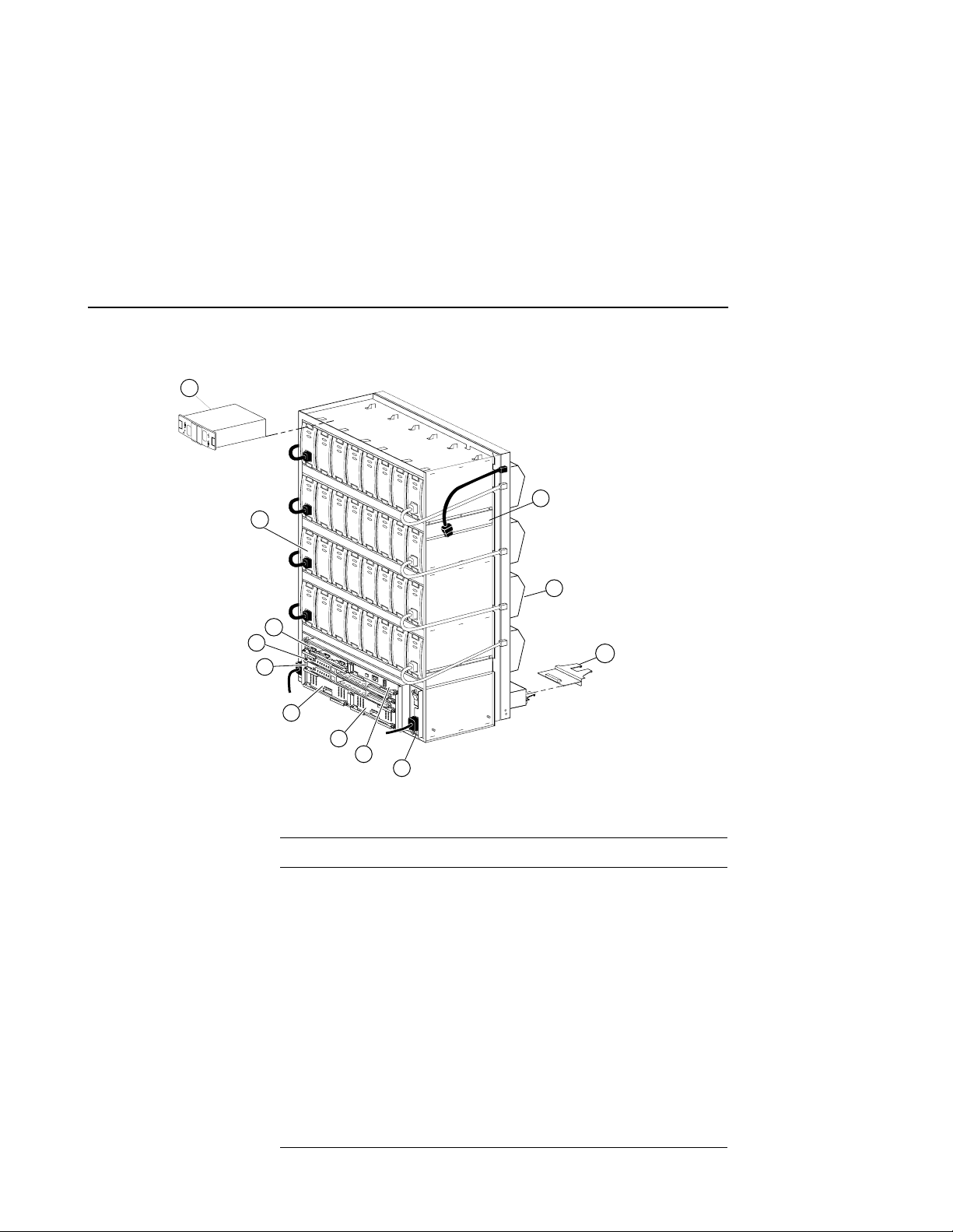
Figure 1–1 The HSG80 Subsystem
12
11
4x
10
9
8
7
General Descrip ti on 1–3
1
2
3
6x
6
5
4
CXO6453A
Table 1–1 Key to Figure 1–1 The HSG80 Subsystem
Item Description Part No.
1 BA370 rack-mountable enclosure DS–BA370–AA
2 Cooling fan DS–BA35X–MK
3 I/O module 70–32876–01
4 AC input module DS–BA35X–HE
5 PVA module DS–BA35X–EC
6 Cache module B 70–33256–01
7 Cache module A 70–33256–01
8 HSG80 controller B 70–33259–01
9 HSG80 controller A 70–33259–01
10 EMU 70–32866–01
Page 28
1–4 HSG80 User’s Gui de
Table 1–1 Key t o Fig u re 1–1 The HSG80 Subsystem (Continued)
Item Descripti on Part No.
11 180-watt power supply DS–BA35X–HH
12 ECB, single
Summary of HSG80 Features
Ta ble 1–2 summarize s the featu r es of the controller.
Table 1–2 Controller Features
Controller Failover
Topology
Supported Operating Systems
Host protocol
Host bus interconnect
ECB, dual
Feature Supported
n
Transparen t Failov er
n
Multiple Bus Failover
n
FC–AL
n
8 nodes per loop; maxi mum
4 initiators per loop
n
single and dual host
adapter(s)
n
2 controller subsystems;
maximum 4 controllers (2
dual-redundant
configurations)
n
128 LUNs in Transparent
and Multiple Bus F ailover
Mode
n
WINNT/Intel
n
WINNT/Alpha
n
FC–AL
n
Copper
Optical : MultiMode 50
Micron
(Do not mix media types)
DS–HS35X–BC
DS–HS35X–BD
n
Gigabit link module (GLM)
Page 29
General Descrip ti on 1–5
Table 1–2 Controller Features (Continued)
Feature Supported
n
Device protocol
Device bus interconnect
SCSI–2
n
Limited SCSI–3
n
Ultra/Fast Wide Sin g leended
n
Number of SCSI device ports
Number of SCSI device tar gets per
6
n
12
port
n
Maximum number of SCSI
72
devices
n
Disk Drives
4 and 9 GB Ultra &
Fast Wide
n
18 GB Ultra
n
4 GB 10K Ultra
n
RAID levels supported
0
n
1
Cache C ap acity
Caching Feature s
Maximum number of RAID-5 and
RAID-1 storagesets
Maximum number of RAID-5
storagesets
n
0+1
n
3/5
n
64 MB and 128 MB
(32 MB DIMMs only)
n
256 MB and 512 MB
(128 MB DIMMs only)
n
Mirrored Cache
n
Sequential Read Ahead
n
Graceful Power Down Policy
n
UPS support with “auto
cache flus h ”
n
30
n
20
Page 30
1–6 HSG80 User’s Gui de
Table 1–2 Controller Features (Continued)
Feature Supported
n
Maximum number of RAID-5,
45
RAID-1, and RAID-0 storagesets
n
Maximum number of partiti ons
8
per storageset or individual disk
n
Maximum number of units
presented to each host
Maximum number of devices per
16 (8 on each of 2 ports) This
is a driver li m i t ation.
n
48
unit
n
Serial interconnect speed
Maximum device, storageset, or
1 GB/second
n
512 GB LUN capacity
unit size
n
Configuration Save
Transfer configuration from
HSZ70 subsyste m to HSG80
controller
n
Transfer configuration from
ACS V 8.0 to ACS V 8.2
n
General Features
Host Modes/Access
Privileges
n
Persistent Reserve s
n
Program card updates
n
Device warm swap
n
Utiliti es to test disks
Page 31

The HSG80 Array Controller
Your controller is the intelli gent bridge between your host and the
devices in your subsystem. As Figure 1–2 illustrates, it bridges the gap
between the host and its storage subsystem.
Figure 1–2 A Host and Its Storage Subsystem
Host
General Descrip ti on 1–7
Storage
subsystem
Hub
Controller
CXO6233B
The controller is an integral part of an y st orage subsystem because it
provide s a host with high-performance and high-avail ability access to
storage devices.
The contro ller provides the ability to comb ine several ordinary disk
drives into a sin g le , h ig h - pe r f o rm an c e en ti t y ca ll ed a s to rag eset.
Storagesets are implementations of RAID technology, which ensures
that every unpartitioned storageset, whether it uses tw o disk drives or
ten, looks li ke a single storage unit to the host. See Chapter 3,
“Creating Storagesets,” for more information about storagesets and
how to configure them.
From the host’s perspective, the controller is simply another device
connected to one of its I/O buses. Consequent ly, the host sends its I/O
requests to the controller just as it would to any Fibre Channel devi ce.
From the subsyst em’s perspecti ve, the controller receives the I/O
requests and directs them to the devices in the subsystem. Because the
Page 32

1–8 HSG80 User’s Gui de
controller proc es ses the I/O requests, the host isn’t burdened by the
processing that’s typically associated with rea ding and writing data to
multiple storage devices.
For the most r ecent list of support ed devices and oper ating systems, see
the product-specific release note s that accompanied your controller’s
software. To determine which specific parts you nee d for your
config uration, see “Connecting the Subsystem to the Host,” page 2–14.
Figure 1–3 and Figure 1–4 detail the HSG80 Array Controller and its
fibre channel components. Figure 1–5 highlights th e variant par ts for an
optical configuration.
Figure 1–3 HSG80 Array Controller Fibre Channel Copper Cabling
2
1
3x
1 2 3 4 5 6
11
2x
12
10
3
2x
4
5
6
7
2x
8
9
To terminal
CXO6467A
Page 33

General Descrip ti on 1–9
Table 1–3 Key t o Fig u re 1–3 HSG80 Array Controller–Fibre
Channel Copper Cabling
Item Description Part No.
1 Backplane connectors —
2 Access Door 70–33287–01
3GLM 30–49226–01
4 Program-card slot —
5 Program-card ejection button —
6 Program card BG–R8Q3B–BA
7 ESD/PCMCIA card cov er 74–52628–01
8 5-meter Fibre Channel copper cable
10-meter Fibre Channel copper cable
9 Maintenance Port Cable
n
See Figure 1–4 for information
17–04718–06
17–04718–07
17–04074–02
on an optional maintenance port
cable and its parts
10 Maintenance Port —
11 Operator control panel (OCP ) —
12 Lever for removing, installing, and
—
retaining cont roller module.
Page 34

1–10 HSG80 User’s Guide
Figure 1–4 Optional Maintenance Port Cable for a Terminal
Connection
1
2
3
4
5
CXO6485A
Table 1–4Key to Figure 1–4: Optional Maintenance Port Cable for
a Terminal Connection
Item Description Part Numb er
1 BC16E-xx Cable Assembly 17–04074–01
2 Ferrite Bead 16–25105–14
3 RJ-11 Adapter 12–43346–01
4 RJ-11 Extension Cable 17–03511–01
5 PC Serial Port Adapter, 9 pin
12–45238–01
D-sub to 25 pin SKT D-sub for a PC
PC Serial Port Adapter, 9 pin D-sub to
12–45238–02
25 pin D-sub for Sun operating system
PC Serial Port Adapter, 9 pin D-sub to
12–45238–03
25 pin D-sub, mod for an HP800
operating system
Page 35

Figure 1–5 HSG80 Array Controller–Fibre Channel Optical Cabling
1
2x
1 2 3 4 5 6
Table 1–5 Key t o Fig u re 1–4 HSG80 Array Controller–Fibre
Channel Optical cabling
Item Descri ption Part No .
1GLM 30–50124–01
General Descrip ti on 1–11
2x
2
CXO6494A
2 2 M Fibre Channel opti cal cable
5 M Fibre Channel optical cable
10 M Fibre Channel optical cable
20 M Fibre Channel optical cable
30 M Fibre Channel optical cable
50 M Fibre Channel optical cable
17–04820–03
17–04820–05
17–04820–06
17–04820–07
17–04820–08
17–04820–09
Caution If the Fibre Channel optical cable is not properly connec ted to
the controller, controlle r f ailure may result. In addition, if the cable is
not regularly maintained, its perf orm ance and lifespan will be affected.
Before proceeding, it is important to administer the precationa ry
measures detailed in the following secti ons.
Fibre Channel Optical Cable Precautions
Prior to connecting the Fibre Channel cable to the controller , look for
the white stripe on each side of the coupling. After the cabl e is seated
into th e co ntroller, be su re that the white strip es are hidden . Also, whe n
connecting the Fibre Channel cable to the controller, listen for a
Page 36

1–12 HSG80 User’s Guide
1. Open the prep cleaner using the lever on the side of the cable cartridge.
2. Rotate the end f ace of the ferrule 180 degrees.
3. Slide the ferrule end face along the opening to one si de of the coupling.
4. Insert a lint-free polyester swab to dust out the cavity.
5. Remove the lint- fr ee pol yset er s w ab, a nd re turn the f err ule t o it s or igina l
6. Repeat 180 de gree rotation in the opposite direction.
7. Slide the ferrule end face along the opening to the oppos ite side.
8. Insert the lint-free polyester swab to dust out the cavity.
distinctive “snap” sound. This will indicate that the cable is properly
insert ed into the controller.
Fibre Channel Optical Cable Cleaning Instructions
It is essential to maintain clean cables to ensure optimum performance
and lifespan of the cable. Figure 1–6 illustrates the proper clean ing
procedures , as outlined in the follo w ing steps:
position.
9. Return to step 5, and re peat remaining procedures until all areas of the
cartr i dge are cleaned.
Note Be sure to clean both cartridges of the fibre ch annel coupling.
Figure 1–6 Fibre Channel Optical Cleaning Procedures
Small diameter
lint-free polyester
swab
Ferrule
CXO6503A
Page 37

General Descrip ti on 1–13
The HSG80 Array Controller components that you will use most ofte n,
such as the maintenance port and the OCP, are conveniently located on
the cont r oller’s front panel. The host port and program-card slot are
also located on the front panel, ma king it easy to update the controller’s
software or to connect the controller to a different host.
Each controller is supported by its own cache module. Figure 1–4
shows which cache module supports which controller in a dualredundant configuration in a BA370 rack-mountable enclosure.
Figure 1–7 Location of Controllers and Cache Modules
Tip D IGITAL recommends that you use the slots for controller A and
cache module A for single configurations. Slot A responds to SCSI target
ID number 7 on device buses; slot B responds to SCSI target ID number
6 on the device buses.
Operator Control Pane l
The operator control panel (OCP) contains a reset button and six port
LED but to ns, as sh own in Fi gu r e 1–5. The reset button flashes about
once per second to indi cate that the controll er is operating normally.
The port button LEDs correspond to the controller’s device ports and
remain off during normal operation. If an error occurs, the reset b utton
and LEDs will illuminate in a solid or flashing pat tern to help you
diagnose the problem. See Appendix C, “LED Codes,” for further
explanation on these codes.
EMU
Controller A
Controller B
Cache module A Cache module B
PVA
CXO6283A
Page 38

1–14 HSG80 User’s Guide
Figure 1–8 HSG80 Controller Operator Control Panel (OCP)
Maintenance Port
Reset button/
LED
123456
Port button/
LED
CXO6216A
To identify the exact lo cation of the OCP, refer to Figu r e 1 –3.
Under normal circumstances, you will not need to remove the
controller from its enclosure. For thi s reason, the components that you
will use most often are conveniently located on the front pan el. For
example, the maintenance port provides a convenient way to connect a
PC or terminal to your controller so that you can interact with it.
After you configure your controller, you should per iodically check its
control panel. If an error occ urs, one or more of the LEDs on the
control panel will flash in a pattern that will help you to diagnose the
problem. See Chapter 4, “Troubleshooting,” for details about
troubleshooting your controller.
You can access the controller through a PC or a local terminal via the
maintenance port, or through a remote terminal—sometimes called a
virtual terminal or host console—via the host. D I G ITAL recomm en d s
that you use a PC or a local term inal to carry out the troubles hooting
and servicing proc edures in this manual. See “Establishing a Local
Connection to the Controller,” page 2–7, for more information on
connecting the controller with a mainte nance port cable.
Utilities and Exercisers
The controller ’s software includes the following utilities and e xercisers
to assist in tro ubleshooting and maintaining the controller and the other
modules that support its operation:
Page 39

General Descrip ti on 1–15
Fault Management Utility
The Fault Managem ent Utility (FMU) provides a limited interface to
the cont r oller’s fault-management system. As a troubleshooting tool,
you can use FMU to display last-failure and memory-system-failure
entries, translate many of the code values contained in event messages,
and set the dis p lay charact eristics of significant events and failures.
See “Fault Manageme nt Utility,” page 4–17, for more information
about using thi s utility.
Virtual Terminal Disp l ay
Use the virtual terminal display (VTDPY) utility to troubleshoot
communicati on between the controller and its host, communicati on
between the controller and the device s in the subsystem, and the state
and I/O activity of the logical units, devices, and device ports in the
subsystem.
See “Using VTDPY to Check for Communication Problems,” page
4–23, for more information about using this utility.
Disk Inline Exerciser
Use the disk inline exer ciser (DILX) to invest igate the data-transfer
capabilities of disk drives. DILX tests and verifies operation of the
contr o ller and the S C SI–2 disk drives attached to it. DILX generate s
intense read and write loads to th e d i sk drive while monitoring the
drive’s performance and status. See “Checking for Disk-Dr ive
Problems,” page 4–37, for more information about this exerciser.
Configuration Utility
Use the configuration (CONFIG) utility to ad d one or mor e storage
device s to the subsystem. This utili ty checks the device ports for new
disk drives then adds them to the controller’s c onfiguration and
automatically names them. See “Adding Several Disk Drives at a
Time,” pa g e 3–55, for more information about using the CONFIG
utility.
Page 40

1–16 HSG80 User’s Guide
HSUTIL
Use HSUTIL to upgrade the firmware on disk drives in the subsystem
and to format disk drives. See “Upgrading Firmware on a Device,”
page 6–11, for more information about this utility.
Code Load and Code Patch Utility
Use Code Load/Code P atch (CLCP) utility to upgrade the controller
software and the EMU software. You can also use it to patch the
controller software. When you install a new controller, you must have
the correct software version and patch number. See “Upgrading
Controller Software,” page 6–2, for more information about using this
utility.
Note Only DIGITAL field service personnel are authorized to upload
EMU microcode updat es . Contact the Customer Service Center (CSC)
for directions in obtaining the appropriate EMU micro code and
installa tion guide.
Clone Utility
Use the Clone utility to duplicate th e data on any unpartitioned singledisk unit, stripeset, or mirrorset. Bac k up the cloned data while the
actual storageset remains online. See “Cloning Data for Backup,” page
3–19, for more information about using the Clone utility.
Field Replacement Utility
Use the field replacement utility (FRUTIL) to replace a failed controller
(in a dual-redundant configuration) without shutting do wn the
subsystem.You can also use this menu-driven utility to replace cache
modules and ext ernal cache batteri es . See Chapter 5, “Replacement
Procedures,” for a more detailed explanation of how to use FRUTIL.
Page 41

General Descrip ti on 1–17
Change Volume Serial Number Utility
Only DIGITIAL authorized service personnel may use this utility.
The Change Volume Serial Number (CHVSN) utility generates a new
volume serial number (call ed VSN) for the spec ified device and writes it
on the media. It is a way to eliminate duplicate volume serial numbers
and to rename duplic ates with different volume serial numbers .
Device Statistics Utilit y
The Device Statistics (DST AT) utility allows you to log I/O activity o n
a controlle r over an e xtended period of time. Later, you can anal yze that
log to determi ne where the bottlenecks are a nd h ow to tune the
controller for optim um perform ance.
Page 42

1–18 HSG80 User’s Guide
Cache Module
Each controlle r requires a companion cache module as shown in Figure
1–9. Figure 1–7 on page 1–13 shows the loca tion of a controller’s
companion cache module. The cache module, whic h can contain up to
512 MB of memory, increases the subsystem’s I/O performance by
providi ng r ea d, read-ahead, write-th rough, and write-back caching.
The size of the memory cont ained in the cache module depends on the
configuration of the DIMMs, with the supported combinations shown
in Table 1–6. For placement of the DIMMs, see “Replacing DIMMs,”
page 5–42.
Table 1–6 Cache Module Memory Configurations
DIMMs Quantity Memory
32 MB 2 64 MB
32 MB 4 128 MB
128 MB 2 256 MB
128 MB 4 512 MB
Page 43

General Descrip ti on 1–19
Figure 1–9 Cac he Module
5
4
3
2x
Item Description Part No.
1 Cache-memory power LED button —
1
~
2
CXO6161A
2 ECB Y cable for the BA370
17–04479–03
Enclosure
ECB Y cable for the Data Center
17–04479–04
Cabinet
3 Retaining lever —
4 Backplane co n nector —
5 64 MB cache upgrade
256 MB cache upgrade
DS-HSDIM-AB
DS-MSDIM-AC
Page 44

1–20 HSG80 User’s Guide
Caching Techniques
The cache module sup ports the following caching techniques to
increase the subsystem’s read and write performance:
n
Read cach i ng
n
Read-ahead caching
n
Write-through ca ch ing
n
Write-back caching
Read Caching
When the controller receives a read req uest from the host, it reads the
data from the disk drives, delivers it to the hos t, and stores the data in
its cache module. This process is called read caching.
Read caching can decrease the subsystem’s response time to many of
the host’s read requests. If the host requests some or all of the cached
data, the controller satisfi es the request from its cache module rather
than from the disk drives. By default, read caching is enabled for all
storage units.
See SET unit number MAXIMUM_CACHED_TRANSFER in
Appendix B, “CLI Commands,” for more details.
Read-Ahead Caching
Read-ahead caching begins when the co ntroller has already processed a
read request, and it receives a sequential read reques t from the host. If
the controller does not find the data in the cache memory, it reads the
data from the disks and sends it to the cache memory.
The controller then anticipates subse quent read requests and begins to
prefetch the next blocks of data from the disks as it sends the requested
read data to the host. This is a parallel action. The controller notifies the
host of the read completion, and subsequent sequential read requests
are satisfied f rom the cach e memory. By default, read- ahead caching is
enabled for all disk units.
Page 45

General Descrip ti on 1–21
Write-Through Caching
When the contr oller receives a write request from the host, it stores the
data in its cache module, writes the data to the d isk drive s, then notifies
the hos t when th e w r it e o peration is co m p l ete. This pr o c ess is calle d
write-thr ough ca ching because the data actually passes through—and is
stored in—the cache memory on its way to the disk drives.
If you enable read caching for a storage unit, write-through caching is
automatically enabled. Likewise, if you disable rea d caching, writethrough caching is automatically disabled.
Write-Back Caching
This caching te chnique improves the subsystem’s response time to
write r eq u est s by a ll owin g th e co n tr o l le r to de cl a re th e w r it e op e r at io n
“complete” as soon as the data rea ches its cache memory. The
controller performs the slower operation of writing the data to the dis k
drives at a la ter time.
By default, write-back caching is enabled for all units. In either case,
the controller will not provide write- back caching to a unit unless the
cache memory is non-volatile, as described in the next section.
Fault-Tol erance for Write-Back Caching
The cache module supports nonvol atile memory and dynamic cache
policies to protect the availability of its unwritten (write-back) data:
Nonvolatil e Memory
The controller can provide write-back caching for any storage unit as
long as the controller’s cac h e memory is nonvolatile . I n other words, to
enable write-back caching, you must provide a backup power source to
the cac he mo du l e to pr e s er ve th e unw r i tt en cache data in th e even t of a
power failure. If the cache memory were volatil e—that is, if it didn’t
have a backup power supply—the unwritte n ca che data would be lost
during a power fa ilure.
By default, the controller expe cts to use an ECB as the backup power
source for its cache module. See “External Cache Battery,” page 1–28,
for more information about the ECB. However, if your subsystem is
backed up by a UPS (uninterruptible power supply), you can tell the
controller to use the UPS as the backup power source with the SET
Page 46

1–22 HSG80 User’s Guide
THIS CONTROLLER CACHE_UP S command. See Appendix B, “CLI
Commands,” for instructions on using this command.
Cache Policies Resulting from Cache Module Failures
If the co ntroller detects a fu l l o r p ar t ial failu re of it s c ac he modul e o r
ECB, it automatically reacts to preserve the unwritten data in its cache
module. Depending upon the severity of the failure, the controller
chooses an interim caching technique (als o called the cache policy)
which it uses until you repair or replace the cache mo dule or ECB.
Table 1-7 sho w s the cache policies result ing from a full or partial
failure of cache module A in a dual-redundant controller configur ation.
The consequences shown in this table are the same for cache module B.
Table 1-7 Cache Policies and Cache Module Status
Cache Module Status Cache Policy
Cache A Cache B U nmirrore d Cache Mirrored Cache
Good Good Data loss: No
Cache policy: Both controllers
support write-back caching.
Failover: No
Multibit
cache
memory
failure
Good Data loss: Forc ed error and los s of
write-back data for which multibit
error occurred. Controller A
detects and repo rts the lost blocks.
Cache policy: Both controllers
support write-back caching.
Failover: No
Data loss: No
Cache policy: Both controllers
support write-back caching.
Failover: No
Data loss: No. Controller A
recovers its lost wr ite-back data
from the m irr o r ed copy on ca ch e B .
Cache policy: Both controllers
support write-back caching.
Failover: No
Page 47

General Descrip ti on 1–23
Table 1-7 Cache Policies and Cache Module Status (Continued)
Cache Module Status Cache Policy
Cache A Cache B U nmirrore d Cache Mirrored Cache
DIMM or
cache
memory
controller
chip
failure
Good Data integrity: Write-back data
that was not writt en to media when
failure occurred was not
recovered.
Cache policy: Controller A
supports writ e-through caching
only; contr oller B supports writeback cach i n g.
Failover: In transparent failover,
all units failover to controller B. In
multiple-bus failover with hostassist, only those units that us e
write-back caching, such as
RAIDsets and mirrorsets, failover
to controller B. All units with lost
data become inoperative until you
clear them with the CLEAR
LOST_DATA command. Units
that di d n’t lose data operate
normally on controller B.
In single contr oll er conf igur ati ons,
RAIDsets, mirrorse ts, an d all uni ts
with lost dat a be come inoperative.
Although you can clear the lost
data errors on some units,
RAIDsets and mirrorsets remain
inoperative until you repair or
replace t he nonvolati le m emory on
cache A.
Data integrity: Controller A
recovers all of its write-back data
from the m irr o r ed copy on ca ch e B .
Cache policy: Controller A
supports writ e-through caching
only; contr oller B supports writeback cach i n g.
Failover: In transparent failover, all
units failover to con tr oller B and
operate normally. In multiple-bus
failover with host-assist, only those
units that use write-back caching,
such as RAIDsets and mirrorsets,
failover to controller B.
Page 48

1–24 HSG80 User’s Guide
Table 1-7 Cache Policies and Cache Module Status (Continued)
Cache Module Status Cache Policy
Cache A Cache B U nmirrore d Cache Mirrored Cache
Cache
Board
Failure
Good Same as for DIMM failure. Data integrity: Controller A
recovers all of its write-back data
from the m irr o r ed copy on ca ch e B .
Cache policy: Both controllers
support write-t hrough caching only.
Controlle r B cannot execute
mirrored writes because cache
module A cannot mirror
controller B’s unwritten data.
Failover: No
Table 1-8 sho ws the cache policies result ing from full or partial failure
of cache module A’s ECB in a dual-redundant configuration. Note that
when cache module A is at least 50% charged, the ECB is still operable
and charging. When it is less than 50% charged, the ECB is low but still
charging. The consequences shown in this table are reciproca l for a
failure of cache module B’s ECB.
Table 1-8 Cache Policies Resulting and ECB Status
Cache Mo dule St atus Cach e Policy
Cache A Cache B Unmirrored Cache Mirrored Cache
At leas t
50%
charged
At leas t
50%
charged
Data loss: No
Cache policy: Both controllers
continue to support write-back
caching.
Failover: No
Data loss: No
Cache policy: Both controllers
continue to support write-back
caching.
Failover: No
Page 49

General Descrip ti on 1–25
Table 1-8 Cache Policies Resulting and ECB Status (Continued)
Cache Mo dule St atus Cach e Policy
Cache A Cache B Unmirrored Cache Mirrored Cache
Less than
50%
charged
At leas t
50%
charged
Data loss: No
Cache policy: Controller A
supports writ e-through caching
only; contr oller B supports writeback cach i n g.
Failover: In transparent failover,
all unit s fai lo ver to contro ller B.
In multipl e-bus failover with host assist, only those units that us e
write-back caching, such as
RAIDsets and mirrorsets, failover
to controller B.
In single configurations, the
controller only provides writethrough caching to its units.
Data loss: No
Cache policy: Both controllers
continue to support write-back
caching.
Failover: No
Page 50

1–26 HSG80 User’s Guide
Table 1-8 Cache Policies Resulting and ECB Status (Continued)
Cache Mo dule St atus Cach e Policy
Cache A Cache B Unmirrored Cache Mirrored Cache
Failed At least
50%
charged
Less than
50%
charged
Less
than
50%
charged
Data loss: No
Cache policy: Controller A
supports writ e-through caching
only; contr oller B supports writeback cach i n g.
Failover: In transparent failover,
all unit s fai lo ver to contro ller B
and operate normally.
In multipl e-bus failover with host assist, only those units that us e
write-back caching, such as
RAIDsets and mirrorsets, failover
to controller B.
In single configurations, the
controller only provides writethrough caching to its units.
Data loss: No
Cache policy: Both controllers
support write-through caching
only.
Failover: No
Data loss: No
Cache policy: Both controllers
continue to support write-back
caching.
Failover: No
Data loss: No
Cache policy: Both controllers
support write-through caching only.
Failover: No
Page 51

General Descrip ti on 1–27
Table 1-8 Cache Policies Resulting and ECB Status (Continued)
Cache Mo dule St atus Cach e Policy
Cache A Cache B Unmirrored Cache Mirrored Cache
Failed Less
Data loss: No
than
50%
charged
Cache policy: Both controllers
support write-through caching
only.
Failover: In transparent failover,
all unit s fai lo ver to contro ller B
and operate normally.
In multipl e-bus failover with host assist, only those units that us e
write-back caching, such as
RAIDsets and mirrorsets, failover
to controller B.
In single configurations, the
controller only provides writethrough caching to its units.
Failed Failed Data loss: No
Cache policy: Both controllers
support write-through caching
only.
Failover: No. RAIDsets and
mirrorsets become inoperative.
Other units that us e write-back
caching o pe rat e w it h wri te through caching only.
Data loss: No
Cache policy: Both controllers
support write-through caching only.
Failover: No
Data loss: No
Cache policy: Both controllers
support write-through caching only.
Failover: No. RAIDsets and
mirro r sets become inoperative.
Other units that us e write-back
caching operate with write-through
caching o nly.
Page 52

1–28 HSG80 User’s Guide
External Cache Battery
To pres er ve the wr i te - b ac k cache data in th e even t o f a p r imary power
failure, a cache module must be connected to an external cache battery
(ECB) or a UPS.
DIGITAL supplies two versions of ECBs: a singl e-battery ECB for
single cont roller configurations, and a dual-batt ery ECB for dualredundant cont roller configurations, which is shown in Figure 1–10.
Figure 1–10ECB for Dual-Redundant Configurations
1
SHUT OFF
STATUS
2
POWER
CACHE
POWER
STATUS
SHUT OFF
4
CACHE
3
~
CXO5713A
Item Description Part No.
Dual battery E CB SB B (St orage
DS–HS35X–BD
Building Block)
Single bat tery ECB SBB DS–HS35X–BC
1 Shut off button —
2 Status LED —
3 ECB Y cable for the BA370 Enclosure
ECB Y cable for the Data Center
17–04479–03
17–04479–04
Cabinet
4 Micro-D port for second batte ry —
Page 53

Charging Diagnostics
General Descrip ti on 1–29
When the batteries are fully charged, an ECB can preserve 512 MB of
cache memory for 24 hours. However , the battery capacity dep ends
upon the size of memory contained in the cache module, as defined in
the Table 1–9.
Table 1–9 E CB Capacity Based on Memory Size
Size DIMM Combinations Capacity
64 MB Two, 32 MB 96 hours
128 MB Four, 32 MB 48 hours
256 MB Two, 128 MB 48 hours
512 MB Four, 128 MB 24 hours
Whenever you restart the controller, its diagnostic routines
automatically check the charge in the ECB’s batteries. If the batteries
are fully charged, the controller reports them as good and rechecks
them every 24 hours. If the batteries ar e cha rging, the control ler
rechecks them every fo u r minutes. Batteries are reported as being eithe r
above or bel ow 50 percent in capacity. Batteries below 50 percent in
capacity are ref erred to as being low.
This four-minute polling conti nues for up to 10 hours—the maximum
time it should take to recharge the batteries. If the batteries have not
been charged s ufficiently after 10 hours, the controller declares them to
be failed.
Battery Hysteresis
When charging a battery, write-back caching wil l be al lowed as long as
a previous down time has not drained more than 50 percent of a
battery’s capacity. When a battery is operating below 50 percent
capacity, the batter y is considered to be low and write-back caching is
disabled.
Caution DIGITAL recommends that you replace the ECB every two
years to prevent battery failure.
Page 54

1–30 HSG80 User’s Guide
Note If a UPS is used for backup power, the controller does not check
the battery. See Appendix B, “CLI Commands,” for information about
the CACHE_UPS and NOCACHE_UPS swit che s .
Page 55

CHAPTER 2
Configuring an HSG80 Array Controller
This chapter explains how to configure an HSG80 Array Controller and the
modules that support its operation in a StorageWorks subsystem.
2–1
Page 56

2–2 HSG80 User’s Guide
Introduction
Configuration Rules
Use the Getting Started Guide that came with your subsystem to
unpack and set up your subsystem prior to configuring your controller.
Unless you specifically request ed a preconfigured subsys tem, you will
have to configure your controller and its subsystem before you can use
them.
For the complete syntax and descriptions of the CLI commands used in
the configuration procedure, see Appe ndix B, “CLI Commands.”
Before you configure your controller, review these configuration rules
and ensure your planne d configuration meets the requirements and
conditions.
n
Maximum 128 visible LUNs/200 assignable unit numbers
n
Maximum 512 GB LUN capacity
n
Maximum 72 physical devices
n
Maximum 20 RAID-5 storagesets
n
Maximum 30 RAID-5 and RAID-1 storagesets
n
Maximum 45 RAID-5, RAID-1, and RAID-0 storages ets
n
Maximum 8 partitions of a storageset or individual disk
n
Maximum 6 members per mirrorset
n
Maximum 14 members p er RAID-5 storage set
n
Maximum 24 members p er Stripese t
n
Maximum 48 physical devices per striped mirrorset
Page 57

Configuring an HSG80 Array Controller 2–3
Configuring an HSG80 Array Controller
You can use this procedure to configure your controller in one of the
follo wing ways:
n
Single controller
n
Dual controllers (in transparent failover mode)
n
Multiple-bus failover (host-assisted), dual-redundant controllers
References sited in the steps below will help you locate detai ls about
the comm an ds and conc epts.
Use the fo llowing steps to configure an HS G 8 0 ar ray controller:
1. Use the power verification and addressing (PVA) module ID switch to
set the SCSI ID number for the BA 370 rack-mountable enclosure.
See “Setting the PVA Module ID Switch,” page 2–6, for details about
PVA switc h settings.
2. Remove the program card ESD cover, and insert the controller’s
program card. Replace the ESD cover.
3. Turn on the power to the pedestal enclosure.
4. Establish a local connection to the controller.
See “Establishi ng a Lo cal Connection to the Controller,” page 2–7, for
details about creating a local conne ction.
5. Choose a config uration fo r the controller:
a. If you are configuring dual- redundant controllers in
transpare nt failover mode, proceed to step 9.
b. If you are configuring dua l-redundant control lers in multiple-
bus (so metim es c a lled hos t - a ssisted) fail over mod e, skip t o
step 10.
6. If the controller reports a node ID of all zeros (0000-0000-0000-0000)
set the subsystem worldwide name (node ID) to the worldwide name
that came with your subsystem. Use the steps in “Restoring Worldwide
Names (Node IDs),” pa g e 3 –26.
7. Set the port topology for each port.
SET THIS_CONTROLLER PORT_1_TOPOLOGY=“topology”
SET THIS_CONTROLLER PORT_2_TOPOLOGY=“
topology”
Page 58

2–4 HSG80 User’s Guide
8. If you selected LOOP_HARD for the port topology, specify the
9. Put “this controller” into transparent failover mode. Use the f ollowing
If this is a single configuration with a single hub, set PORT 2 off-line.
If this is a dual-redundant configuration, the “other controller” inherits
“this controller’s” port topology.
See Appendix B, “CLI Commands,” for more information about using
the SET THIS_CONTROLLER PORT_n_TOPOLOGY= command.
arbitrated loop physical address (ALPA) for the host ports.
SET THIS_CONTROLLER PORT_1_ALPA=“address”
SET THIS_CONTROLLER PORT_2_ALPA=“address”
If this is a dual-redundant configuration, the “other controller” inherits
“this controller’s” port ALPA addresses.
See Appendix B, “CLI Commands,” for more information about using
the SET OTHER_CON T ROLL ER PO RT_n_ALPA= command.
syntax:
SET FAILOVER COPY = THIS_CONTROLLER
The “other controller” inheri ts “this controller’s” configuration, then
restarts. Wait for it to return to normal operation before continuing.
See details abou t failover modes in “Select in g a Failover Mode,” page
2–10.
10. Put “this controller” in multiple-bus failover mode using the follwing
syntax:
SET MULTIBUS_FAILOVER COPY=THIS_CONTROLLER
The “other controller” inheri ts “this controller’s” configuration, then
restarts. Wait for it to return to normal operation before continuing.
See “Selecting a Failover Mode,” page 2–10 , f or details about failove r
modes.
11. Optional: Change the CLI prompt. Type the following command:
SET THIS_CONTROLLER PROMPT = “new prompt”
Page 59

Configuring an HSG80 Array Controller 2–5
If you’re c onfiguring dual-redundant controlle r s , also change the CLI
prompt on the “other controlle r.” Use the following syntax:
SET OT HER_ CO NT ROL LER PRO MP T = “new prompt”
See Appendix B, “CLI Commands,” for more information about using
the SET OTHER_CONTROLLER PROMPT= command.
12. Optional: Indicate that your subsys tem power is supported by a UPS.
Use the following syntax:
SET THIS_CONTROLLER CACHE_UPS
The “other controller” inheri ts “this controller’s” cache UPS setting.
See “Backing up Power with a UPS,” page 2–13, for more information.
13. Restart the controller, using the following syntax:
RESTART THIS_CONTROLLER
If this is a dual-redundant configuration, restart the “other controller”
using the following syntax:
RESTART OTHER_CONTROLLER
See the RESTART THIS_CONTROLLER command in Appendix B,
“CLI Commands,” for more information about using this command.
14. When the CLI prompt reappears, it will display details about the
controller you configured. Use the following syntax:
SHOW THIS_CONTROLLER FULL
See the SHOW THIS_CONTROLLER FULL command in Appendix
B, “CLI Commands,” for more information about using this command.
15. Connect the controller to the host.
See “Connecting the Sub system to the Host,” page 2–14 for
information about how to complete the connection.
16. Plan and configure storages ets for your subsystem.
See Chapter 3, “Creating Storagesets,” for detailed information about
planning and configuring storagesets.
Note If you have probl ems during the configuration, use the SET
NOF AILOVER and CONFIGURATION RESTORE commands to reset
the system to the factory settings. You must reset the controller after
these co mmands ar e en t er ed to employ th e origina l settings .
Page 60

2–6 HSG80 User’s Guide
Setting the PVA Module ID Switch
The Power, Verification, and Addressing (PVA) module provides
unique addresses to extended subsystems. Each BA370 rack-mountable
enclosure in an extended subsystem must ha ve its own PVA ID. Use
PVA ID 0 for the enclosure that c ontains the array controllers. Use PVA
IDs 2 and 3 for the additional enc los ures. Figure 2–1 illustrates the
PVA settings in an extended subs ystem.
See the documenta tion that accompanied your enc losure for more
details about the PVA and its settings.
Figure 2–1 SCSI Target ID Numbers on the Controller Device Bus and PVA Settings in an
Extended Subsytem
First Expansion
Enclosure
SCSI Target ID = 11
SCSI Target ID = 10
SCSI Target ID = 9
SCSI Target ID = 8
EMU
OTE: SCSI target IDs 4 and 5 are reserved. IDs 6 and 7 are used by the controllers.
PVA 2
Master
Enclosure
SCSI Target ID = 3
SCSI Target ID = 2
SCSI Target ID = 1
SCSI Target ID = 0
EMU
Controller A
Controller B
PVA 0
Cache B Cache A
Second Expansion
SCSI Target ID = 15
SCSI Target ID = 14
SCSI Target ID = 13
SCSI Target ID = 12
Enclosure
EMU
PVA 3
CXO5806B
Page 61

Configuring an HSG80 Array Controller 2–7
Establishing a Local Connection to the Controller
You can communicate with a controller locally or remotely. Use a local
connection to configure the controller for the first time. Use a remote
connection to your host system for all subseque nt configuration tasks.
See the Getting Started Guide that came with your platfo rm kit for
details.
The maintenan ce po rt provides a convenient way to connect a PC or
terminal to the controller so that you can troubleshoot and conf igure it.
This port acc epts a standard RS-232 jack from any EIA-423 compatible
terminal or a PC with a terminal-emulation program. The maintenance
port supports ser ial communications with default value s of 9600 baud
using 8 data bit s, 1 stop bit, and no parity.
Note The maintenance port cable shown in Figure 2–2 has a 9-pin
connector molded onto its end for a PC connection. If you need a
terminal conne ction, see Figure 1–4 on page 1–10 for information on
optional cabling.
Figure 2–2 Terminal to Local-Connection Port Connection
1 2 3 4 5 6
Maintenance
port
Maintenance
port cable
CXO6476A
Page 62

2–8 HSG80 User’s Guide
1. Turn off the PC or terminal, and connect it to the controller, as shown i n
2. Turn on the PC or terminal.
3. Configure the terminal for 9600 baud, 8 dat a bits, 1 stop bit, and no
Caution The local-connection port described in this book generates,
uses, and can radiate radio-frequency energy through cables that are
connected to it. This energy may interfere with radio and tele vision
reception. Do not leave any cable s connected to it when you are not
communicati ng with the controller.
Follow these steps to establish a local connectio n for setting the
controller’s initial configuration:
Figure 2–2.
a. For a PC connection, plug one end of the maintenanc e port
cable into the terminal; plug th e o ther end into the controller’s
maintenance port.
a. For a t er mi nal con nec ti on, ref er to Figure 1–4 on pag e 1–10 for
cabling information.
parity.
4. Press the Enter or Return key. A copyright notice and the CLI prompt
appear, indicating that you established a local connection with the
controller.
5. Optional: to inc r ea se the data transfer rate to 19200 baud:
a. Set the controller to 19200 baud with one of the following
commands:
SET THIS_CONTROLLER TERMINAL SPEED=19200
SET OTHER_CONTROLLER TERMINAL SPEED=19200
b. Configure the PC or terminal for 19200 baud.
When you are entering CLI commands in a dual-redundant controller
config uration , remember that the conroll er to which you’re connected is
“this controller” and the remaining controller is the “other controller”.
See Figure 2–3.
Page 63

Configuring an HSG80 Array Controller 2–9
Figure 2–3 “This C o n t rol ler” and “Other Controller”
Other controller
This controller
CXO6468B
Page 64

2–10 HSG80 User’s Guide
Selecting a Failover Mode
When selecti ng a failover mode, use transparent failover if you want the
failover to occur without any intervention from the host, or employ
multiple-bus failover if you want the host to send comma nds to the
companion array co ntroller.
Using Transparent Failo ver
Transparent failover is a dual-redundant controller configuration in
which two controllers are connected to the same host and device buses.
Use this configuration if you want to use two controllers to service the
entire group of storagesets, single-dis k units, and other storage de vices.
Because both cont rollers service the sa me storage units, either
controller can contin ue to service all of the units if its comp anion
controller fails.
Transpare n t fa il ove r o cc u rs when a con tro ll er fails or a us er pr e ss es the
reset button on one of the controllers. To configure controllers for
transpare nt failover, moun t both controllers in the s am e BA370 pedestal
and fo llow th e steps in “Configuring an HSG80 Array Cont roller,” page
2–3.
Keep the following tips in mind if you configure controllers for
transparent failover:
n
Set your controllers for transparent fail over before conf iguring
devices. Once the devices, storagesets, and units are added to one
controller’s configuration, they are automatically added to the
other’s.
n
If you decide to configure your devices before setting the
contr o llers fo r tr a n s p arent failover, ma ke sure y ou kn ow which
controller ha s the good conf igu ration i nformat ion before spec ifying
SET FAILOVER COPY=. See Appendix B, “CLI Commands,” for
details about the SET FAILOVER COPY= command.
n
Balance your assignment of devices. F or example, in an18-device
subsystem, place 3 devices on each of the 6 ports, rather than
placing 6 de vices on each of 3 ports.
n
The controller to whi ch you c opy confi gura tion in format ion r estarts
after you enter the SET FAILOVER command.
Page 65

Using Multiple-Bus Fail over
Multiple-bus (or host-assisted) failover is a dual-redundant controller
configuration in which each array controller has its own connection to
the host. Thus, if one of the host connections to an array c ontroller
fails, the host can cause units that became inacces sible to failover to the
remaining viable connection. Be cause both array controllers service t he
same storage unit s, either array controller can continue to service all of
the units if the other array controller fails.
Keep the following points in mind when considering using multiple-bus
failover:
n
n
n
n
Configuring an HSG80 Array Controller 2–11
The host distributes the I/O load between the array controllers.
The host must have two Fibre Channel adapters as well as
operating-system software to support the multiple-bus failover,
dual-redundan t controller configuration.
Mount both array cont rollers in the same BA370 rack-mountable
enclosure and follow the steps in “Configuring a n HSG80 Array
Controller,” page 2–3.
Partit ioning is not supported.
Page 66

2–12 HSG80 User’s Guide
Enabling Mirrored Write-Back Cache
Before configuring dual-redundant c ontrollers and enabling mirro ring,
ensure the following conditions are met:
n
Both array controllers support the same size cache, 64 MB, 128
MB, 256MB, or 512 MB.
n
Diagnostics indicates that both caches are good.
n
Both caches have a battery present, if you have not enabled the
CACHE_UP S switch. A battery does not have to be present for
either cach e if you e n able the CACHE_UPS switch.
n
No unit errors are outstanding, for example, lost data or data that
cannot be writte n to devices.
n
Both array controllers are started and c onfigured in failover mode.
For important considerations when addi ng or replacing DIMMs in a
mirro r ed cache con figuration, see “Replacing DIMMs,” page 5–42.
Selecting a Cache Mode
Before selecting a cache mode you should understand the caching
techniques su pported by the cache module.
Fault-Tolerance
The cache module supports read, read-ahead, write-through, and writeback caching t echniques that you ca n enable separately for each storage
unit in a subsystem. For example, you can enable only read and writethrough cachin g for some units while enabling only write-back caching
for other units.
For details about these caching techniques, see“Caching Techniques,”
page 1–20.
The cache module supports the following features to protect the
availability of its unwritten (write-back) data:
n
Nonvolatile memory (required for write-back caching).
n
Dynami c caching te ch n i qu e s (a u tom a ti c) .
For details about the se fea tures, see “Fault-Tolerance for Write-Back
Caching,” page 1–21.
Page 67

Backing up Power with a UPS
By defau lt , th e con t r o ll er expects to use an ext er n a l cache batte r y
(ECB) as backup power to th e cache module. You can also opt to use an
uninterruptable power supply (UPS) to provide backup power in the
event of a primary power failure. See Appendix B, “CLI Commands,”
for details about the SET THIS_CONTROLLER CACHE_UPS
command. See Table 1-7 on page 1–22 and Table 1-8 on page 1–24 for
information about cache policies.
Configuring an HSG80 Array Controller 2–13
Page 68

2–14 HSG80 User’s Guide
Connecting the Subsystem to the Host
This sectio n des cribes how to connect your subsystem to a host. It also
includes instructions for connecting a single (nonredundant) controller
and dual-redunda nt controllers to the host.
Caution Do not attempt to configure dua l-redundant controllers using
one hub with a loopback cable. This configuration will cause data
corruptio n and is not supported.
Connecting a Single Controller to the Host Using One Hub
There are two possible configurations for a single controller, one tha t
uses a single hub, and a second that uses two hubs. The second
config uration can be used if you have two hosts to which you’re
connecting to your controller.
Figure 2–4 Cabling for Single Configuration with Fibre Channel Copper Support
1
2
1 2 3 4 5 6
3
To host
CXO6115A
Table 2–1 Key t o Fig u re 2–4 Cabling for Single Configuration
(copper)
Item Description Part No.
1 Single Cont roller 70-3 3259-xx
2 9-Port Fibre Channel HUB DS-DHGGA-CA
3 5-meter copper Fibre Channel cable or
10-meter copper Fibre Channel cable
17-04718-06
17-04718-07
Page 69

Configuring an HSG80 Array Controller 2–15
Use the follo wing steps to connect a sing le, nonredundant controller to
the host using one hub:
1. Stop all I/O from the host to its devices on the bus to which you are
connecting the controller.
2. Connect the Fibre Channel cable from Port 1 on the controll er to P ort 1
of the hub.
For this configuration, set Port 2 off-line using the SET
THIS_CONTROLLER PORT_2_TOPOLOGY=OFFLI NE command.
See Appendix B, “CLI Commands,” for details about the SET
command.
3. Follow the procedures in the Getting Started Guide for connecting the
Fibre Channel ca ble from the hub to your host system.
4. Route and tie the cables as desired.
Restart the I/O from the host. Some operating systems may requi re you
to restar t the host to see the devices atta ched to the new contr oller .
Figure 2–5 Cabling for Single Configuration with Fibre Channel Optical Support
3
To host
1
1 2 3 4 5 6
2
CXO6495A
Page 70

2–16 HSG80 User’s Guide
Table 2–2 Key t o Fig u re 2–5 Cabling for Single Configuration
(optical)
Item Description Part No.
1 Single Cont roller 70–33259–xx
2 .5 M Fibre Channel Optic cable
1 M Fibre Channel Optic cable
2 M Fibre Channel Optic cable
3 M Fibre Channel Optic cable
5 M Fibre Channel Optic cable
10 M Fibre Channel Optic cable
20 M Fibre Channel Optic cable
30 M Fibre Channel Optic cable
50 M Fibre Channel Optic cable
100 M Fibre Channe l Op tic cable
200 M Fibre Channe l Op tic cable
400 M Fibre Channe l Op tic cable
17–04820–01
17–04820–02
17–04820–03
17–04820–04
17–04820–05
17–04820–06
17–04820–07
17–04820–08
17–04820–09
17–04820–10
17–04820–11
17–04820–12
3 12-Port Fibre Channel HUB DHGGA-CA
Use the follo wing steps to connect a sing le, nonredundant controller to
the host using one hub:
1. Stop all I/O from the host to its devices on the bus to which you are
connecting the controller.
2. Connect the Fibre Channel cable from Port 1 on the controller to Port 1
of the hub.
For this configuration, set Port 2 off-line using the SET
THIS_CONTROLLER PORT_2_TOPOLOGY=OFFLI N E command.
See Appendix B, “CLI Commands,” for details about the SET
command.
3. Follow the procedures in the Getting Started Guide for connecting the
Fibre Channel ca ble from the hub to your host system.
4. Route and tie the cables as desired.
5. Restart the I/O from the host. Some operating systems may requi re you
to restar t the host to see the devices atta ched to the new contr oller .
Page 71

Configuring an HSG80 Array Controller 2–17
Connecting a Dual-Redundant Contr oller Configuration to the Host
There are two possible ways to connect dual-re dundant controllers to
your host. The first method requires two hubs; the second method
requires one hub.
Using Two Hubs
Use the followin g steps and Fig u r e 2 –6 to connect your dual-redundant
controllers to the host using two hubs with copper support.
Figure 2–6 Cabling for Dual-Redundant Configuration with Two Hubs using Fibre Channel
Copper Support
1
To host
2
1 2 3 4 5 6
1 2 3 4 5 6
To host
3
2
Table 2–3 Key t o Fig u re 2–6 Cabling for Dual-Redundant
Configuration with Two Hubs (copper)
Item Description Part No.
1Dual Controller —
2 9-port Fibre Channel HUB DS–DHGGA–CA
3 5-meter ho st F ibr e Ch a n ne l cable
10-meter host Fibre Channel cable
17–04718–06
17–04718–07
CXO6167A
Page 72

2–18 HSG80 User’s Guide
1. Stop all I/O from the host to its devices on the bus to which you are
2. Connect the Fibre Channel cable from Port 1 on controller A to Port 9
3. Connect anot her Fibre Channe l c able from Port 2 on cont roll er A to Por t
4. Connect each hub to their respective host according to the instructions
5. Route and tie the cables as desired.
connecting the controllers.
on hub 1. Repeat this step to connect the second cable from Port 1 on
controller B to Port 8 on hub 1.
1 on hub 2. Repeat this step to connect the final cable from Port 2 on
controller B to Port 2 on hub 2.
in the Getting Started manual.
Restart the I/O from the host. Some operating systems may requi re you
to restar t the host to see the devices atta ched to the new contr oller .
Page 73

Configuring an HSG80 Array Controller 2–19
Use the followin g steps and Fig u r e 2 –7 to connect your dual-redundant
controllers to the host using two hubs with optical support:
Figure 2–7 Cabling for Dual-Redundant Configuration with Two Hubs using Fibre Channel
Optical Support
2
To host
1
1 2 3 4 5 6
2
1 2 3 4 5 6
3
To host
CXO6496A
Page 74

2–20 HSG80 User’s Guide
Table 2–4 Key t o Fig u re 2–7 Cabling for Dual-Redundant
Configuration with T wo Hubs (optical)
Item Description Part No.
1Dual Controller —
2 12-Port Fibre Channel HUB DHGGA-CA
3 .5 M Fibre Channel Optic cable
1 M Fibre Channel Optic cable
2 M Fibre Channel Optic cable
3 M Fibre Channel Optic cable
5 M Fibre Channel Optic cable
10 M Fibre Channel Optic cable
20 M Fibre Channel Optic cable
30 M Fibre Channel Optic cable
50 M Fibre Channel Optic cable
100 M Fibre Channe l Op tic cable
200 M Fibre Channe l Op tic cable
400 M Fibre Channe l Op tic cable
17–04820–01
17–04820–02
17–04820–03
17–04820–04
17–04820–05
17–04820–06
17–04820–07
17–04820–08
17–04820–09
17–04820–10
17–04820–11
17–04820–12
1. Stop all I/O from the host to its devices on the bus to which you are
connecting the controllers.
2. Connect the Fibre Channel cable from Port 1 on controller A to Port 9
on hub 1. Repeat this step to connect the second cable from Port 1 on
controller B to Port 8 on hub 1.
3. Connect anot her Fibre Channe l c able from Port 2 on cont roll er A to Por t
1 on hub 2. Repeat this step to connect the final cable from Port 2 on
controller B to Port 2 on hub 2.
4. Connect each hub to their respective host according to the instructions
in the Getting Started manual.
5. Route and tie the cables as desired.
6. Restart the I/O from the host. Some operating systems may requi re you
to restar t the host to see the devices atta ched to the new contr oller .
Page 75

Configuring an HSG80 Array Controller 2–21
Using One Hub
Use the followin g steps and Fig u r e 2 –8 to connect your dual-redundant
controllers to the host using one hub with copper support:
Figure 2–8 Cabling for Dual-Redundant Configuration with One
Hub using Fibre Channel Copper Support
1
1 2 3 4 5 6
1 2 3 4 5 6
3
2
To host
CXO6234A
Table 2–5 Key t o Fig u re 2–8 Cabling for Dual-Redundant
Configuration with One Hub using Fibre Channel
Copper Support
Item Descri ption P art No.
1Dual Controller —
2 9-port Fibre Channel HUB DS-DHGGA-CA
3 5-met er hos t F ibr e Ch a n ne l cable
10-meter host Fibre Channel cable
17-04718-06
17-04718-07
1. Stop all I/O from the host to its devices on the bus to which you are
connecting the controllers.
2. For this configuration, set Port 2 off-line using the SET
THIS_CONTROLLER PORT_2_TOPOLOGY=OFFLI NE command.
See Appendix B, “CLI Commands,” for details about the SET
command.
Page 76

2–22 HSG80 User’s Guide
3. Connect the Fibre Channel cable from Port 1 on controller A to Port 9
on hub 1. Repeat this step to connect the second cable from Port 1 on
controller B to Port 8 on hub 1.
4. Connect anot her Fibre Channe l c able from Port 2 on cont roll er A to Por t
1 on hub 2. Repeat this step to connect the final cable from Port 2 on
controller B to Port 2 on hub 2.
5. Connect each hub to their respective host according to the instructions
supplied in the Getting Started manual.
6. Route and tie the cables as desired.
7. Restart the I/O from the host. Some operating systems may requi re you
to restar t the host to see the devices atta ched to the new contr oller .
Use the followin g steps and Fig u r e 2 –9 to connect your dual-redundant
controllers to the host using one hub with copper support:
Figure 2–9 Cabling for Dual-Redundant Configuration with One Hub using Fibre Channel
Optical Support
1
1 2 3 4 5 6
1 2 3 4 5 6
3
To host
2
CXO6497A
Page 77

Configuring an HSG80 Array Controller 2–23
Table 2–6 Key t o Fig u re 2–9 Cabling for Dual-Redundant
Configuration with One Hub using Fibre Channel
Optical Support
Item Description Part No.
1Dual Controller —
2 12-Port Fibre Channel HUB DHGGA-CA
3 .5 M Fibre Channel Optic cable
1 M Fibre Channel Optic cable
2 M Fibre Channel Optic cable
3 M Fibre Channel Optic cable
5 M Fibre Channel Optic cable
10 M Fibre Channel Optic cable
20 M Fibre Channel Optic cable
30 M Fibre Channel Optic cable
50 M Fibre Channel Optic cable
100 M Fibre Channe l Op tic cable
200 M Fibre Channe l Op tic cable
400 M Fibre Channe l Op tic cable
17–04820–01
17–04820–02
17–04820–03
17–04820–04
17–04820–05
17–04820–06
17–04820–07
17–04820–08
17–04820–09
17–04820–10
17–04820–11
17–04820–12
1. Stop all I/O from the host to its devices on the bus to which you are
connecting the controllers.
2. For this configuration, set Port 2 off-line using the SET
THIS_CONTROLLER PORT_2_TOPOLOGY=OFFLI NE command.
See Appendix B, “CLI Commands,” for details about the SET
command.
3. Connect the Fibre Channel cable from Port 1 on controller A to Port 9
on hub 1. Repeat this step to connect the second cable from Port 1 on
controller B to Port 8 on hub 1.
4. Connect anot her Fibre Channe l c able from Port 2 on cont roll er A to Por t
1 on hub 2. Repeat this step to connect the final cable from Port 2 on
controller B to Port 2 on hub 2.
5. Connect each hub to their respective host according to the instructions
supplied in the Getting Started manual.
6. Route and tie the cables as desired.
7. Restart the I/O from the host. Some operating systems may requi re you
to restar t the host to see the devices atta ched to the new contr oller .
Page 78

Page 79

CHAPTER 3
Creating Storagesets
This chapter provides information to help you create storagesets for your
subsystem. Th e proc edure in this chapter takes you through the planni ng steps and
procedures for creating storagesets.
3–1
Page 80

3–2 HSG80 User’s Guide
Introduction
Storagesets are implementations of RAID technology, also known as a
“Redundant Array of Independent Disks.” Every storageset shares one
important feature: each one looks lik e a single storage unit to the host,
regardless of the number of drives it uses .
You can create storage units by combining disk drive s into storagesets,
such as str i p esets, RAID sets, and mir ro rsets, or by presenting th em to
the host as sing le-disk units, as shown in Figure 3–1.
n
Stripesets (RAID 0) combine dis k d r ives in serial to increase
transfer or request rat es.
n
Mirror s et s ( RA I D 1) combin e d isk dr ives in p ar a ll el to pr ovid e a
highly-reliable storage unit.
n
RAIDsets (RAID 3/5) combine disk drives in serial—as do
stripesets—but also store pa rity data to ensure high reliabi lity.
n
Striped mirrorsets (RAID 0+1) combine mirrorsets in seri al to
provide the highest throughput and availability of any storage unit.
Controllers can support the number of RAIDsets as lis ted in Table 3-1.
For a complete discussion of RAID, refer to The RAIDBOOK —A
Source Book for Disk Array Technology.
Page 81

Creating Storagesets 3–3
Figure 3–1 Units Created from Storagesets, Partitions, and
Drives
Unit
Unit
Stripeset
Mirrorset
RAIDset
Disk drives
Unit
Table 3–1 Controller Limitations for RAIDsets
RAIDset Type Limit
Total number of RAID5 20
Total number of RAID5 + RAID1 30
Total number of RAID5 + RAID1 + RAID0 45
Partitioned
disk drive
Unit
Unit
Partitioned
storageset
Unit
Striped
mirrorset
CXO5368B
Page 82

3–4 HSG80 User’s Guide
Planning and Configuring Storagesets
Use this procedure to plan and configure the storagesets for your
subsystem. Use the references in each step to lo ca te details about
specific co mmands an d co nc ep t s .
1. Create a storageset and device profile. See “Creating a Storagese t and
Device Profile,” page 3–5, for suggest ions about creating a profile.
2. Determine your storage requirements. Use the questions in
“Determining Storage Requirements,” page 3–7, to help you.
3. Choose the type of storagesets you need to use in your subsystem. See
“Choosing a Storage set Type,” page 3–8, for a comparison and
description of ea ch type of storageset.
4. Select names for your storagesets and units. See “Creating a St or a g es e t
Map,” page 3–32, for details about selecting names.
5. Assign unit numbers to storagesets so the host can access the units.
See“Creating a Storageset Map,” page 3–32, for information about how
to assign units numbers to storagesets.
6. Create a storageset map to help you configure your subsystem. See
“Creating a Storageset Map,” page 3–32, for suggestions about creating
a storageset map.
7. If you are going to parti tion your storagesets, pl an the partitions. See
“Planning Partitions,” page 3–37, for information about partitions and
how to plan for them.
8. Choose the switc hes that you will want to set for your stora ges ets and
device s. See“Choosing Switches for Stor age sets and Devices,” page
3–39, for a description of the switches you can select for storagesets.
9. Configure the storagesets you have planned using one of these methods:
n
Use StorageWorks Command Console (SWCC), a Graphical User
Interface (GUI) , to set up and manage RAID storage subsystems.
See t h e SWCC Getting St arted guide for details about using SWCC
to configure your storagesets.
n
Use CLI commands. This method allows you flexibility in defining
and naming storagesets. See “Configuring Storagesets with CLI
Commands,” page 3–55, for informat ion about configuring each
type of storages et using CLI commands.
Page 83

Creating a Storageset and Device Profile
Creating a profile for your storagesets and devices c an help simplify the
config uration process. This chapter helps you to choose the s toragesets
that best suit your needs and make informed decis ions about the
switches that you ca n enable for each storageset or stora ge device that
you configure in your subsystem.
Familiarize yourself with the kinds of information contained in a
storageset profile, as shown in Figure 3–2.
Appendix A, “System Profiles,” contains blank profiles that you can
copy and use to record the de tails for your storageset s. Use the
information in this chapter to help you make decisions when creating
storageset profiles.
Creating Storagesets 3–5
Page 84

3–6 HSG80 User’s Guide
Figure 3–2 A Typical Storage s et Profile
Type of st o r ageset
_____ Mirrorset __✔_ RAIDset _____ Stripeset _____ Strip ed Mirrorset
St orageset Name... accept default values
Disk Drives............ DISK10300, DISK20300, DIS30300
Unit Number....... .. acc e p t d e fa ul t
Partitions
Unit # Unit # Unit # Unit # Unit # Unit # Unit # Unit #
%%%%%%%%
RAIDset Sw itches
Reconstruction Policy Reduced Membership Replacement Policy
_✔ Normal (default)
___ Fast
_✔ No (default)
___ Yes, missing:
_✔ Best perf ormance (default)
___ Best fit
___ None
Mirrorset Switches
Replacement Policy C opy Policy Read Source
___ Best performance (default)
___ Best fit
___ None
___ Normal (default)
___ Fast
___ Least busy (default)
___ Round robin
___ Disk drive:
Initialize Switch es
Chunk size Save Configur ation Metadata
✔ Automatic (defau lt)
___ 64 blocks
___ 128 blocks
___ 256 blocks
___ Other:
___ No (default)
Yes
_✔
Unit Switches
Read Cache Read-Ahead Cache Maximum Cache Transfer
✔ Yes (default)
___ No
Write Cache Write Protection Availability
___ Yes (default)
✔ No
✔ Yes (default)
___ No
✔ No (defau lt)
___ Yes
✔ 32 blocks (default)
___ Other:
✔ Run (default)
___ NoRun
✔ Destroy (defau lt)
___ Retain
Page 85

Determining Storage Requirements
Start the planning process by determining your storage requirements.
Here are a few of the quest ions you should ask yourself:
n
What applications or user groups will access the subsystem? How
much cap acity do they ne ed ?
n
What are the I/O requirements? If an application is data-transfer
intensive, what is the required transfer rate ? I f it is I/O-request
intensive, what is the required res ponse time? What is the read/
write ratio for a typical request ?
n
Are most I/O requests directed to a small percentage of the disk
drives? Do you want to keep it that way or balance the I/O load?
n
Do you store mission-critical data? Is availability the highest
priority, or would standard backup procedures suffice?
Use your responses to these questions along with Figure 3–2 to
determine the types of storagesets you should create to satisfy your
organization’s requirements.
Creating Storagesets 3–7
Page 86

3–8 HSG80 User’s Guide
Choosing a Storagese t Type
Different applications may have different storage requirements, so you
will probably want to configure more tha n one kind of storageset in
your subsystem.
All of the storages ets described in this book impl em ent RAID
(Redundant Array of Independent Disks) technology. Consequently,
they all share on e important feature: each storag eset, whether it
contains tw o dis k drives or ten, looks like one large, virtual disk drive
to the ho s t.
Ta ble 3–2 compares differen t kinds of storagesets to help you
determine which ones satisfy your requirements.
Table 3–2 A Comparison of Different Kinds of Storagesets
Request Rate
(Read/Write)
I/O per second
Identical to single
disk drive
Excellent if used
with large chunk
size
Storageset
Array of disk driv es
(JBOD)
Stripeset
(RAID 0)
Relative
Availability
Equivalent to a
single disk dr ive
Proportionate to
number of disk
drives; w ors e th an
single disk dr ive
Mirrorset
Excellent Good/Fair Good/Fair System drives;
(RAID1)
RAIDset
Excellent Excelle nt/Fa ir Good/Poor High request rat es,
(RAID 3/5)
Striped Mirrorset
Excell ent Excellen t if u sed
with large chunk
(RAID 0+1)
size
For a comprehensive discussion of RAID, refer to The RAIDBOOK—A
Source Book for Disk Array Technology.
Using St r i p e sets to Increase I/ O Performanc e
Stripesets en hanc e I/O performance by spreading the data across
multiple di sk drives. Each I/O requ est is broken into small segments
Transfer Rate
(Read/Writ e) MB
per second
Identical to single
disk drive
Excellent if used
with small chunk
size
Excellent if used
with small chunk
size
Applications
High performance
for non-critical
data
critical files
read-intensive,
data lookup
Any critical
response-time
application
Page 87

Creating Storagesets 3–9
called “chunks.” These chunks are then “striped” across the disk dr ives
in the storageset, thereby allowing several disk drives to participate in
one I/O request to handl e s everal I/O requests si mul taneously.
For example, in a three-member stripeset that contains disk drives
10000, 20000, and 30000, the first chunk of an I/O request is written to
10000, the s econd to 20000, the third to 30000, the fourth to 10000, and
so forth until all of the data has been written to the drives.
Figure 3–3 Striping Lets Several Disk Drives Parti cipate in Each
I/O Request
6
Chunk 1
1
2
3
0
0
1
0
k
0
s
i
D
4
0
2
0
k
0
s
i
D
2
5
5
4
0
3
0
k
0
s
0
i
D
36
0
CXO5507A
The relationship between the chunk size and the average request size
determines if striping maximizes the request rat e or the data-transfer
rate. You can set the chunk size or let the controller set it autom atically.
See “Chunk Size,” page 3–47, for information about setting the chunk
size.
A major benef it of striping is that it balanc es the I/O load across all of
the disk d r ives in the storageset. This can increase the subsystem’s
performance by el im inating the hot spots, or high localities of
reference, that occ ur when frequently-accessed data beco mes
concentrat ed on a single disk drive.
Page 88

3–10 HSG80 User’s Guide
Considerations for Planning a Stripeset
Keep the following points in mind as you plan your stripesets:
n
A controller can supp ort up to 45 storagesets, consisting of
stripesets, mirrorsets and RAIDsets (refer to Table 3–1).
n
Reporting methods and size limitati ons prevent certain operating
systems from working with large stripesets. See the HSG80 Array
Controller ACS Version 8.2G Rel eas e Notes or the Getting Start ed
Guide that came with your platform kit for details about these
restrictions.
n
A storageset should only contain disk drives of the same capacity.
The cont ro ller l imit s t he c apa ci ty of ea ch mem ber to th e ca pa ci ty of
the smallest member in the storageset when the storageset is
initialized (the base member s ize). Thus, if you c omb ine 9 GB disk
drives with 4 GB disk drives in the same storageset, the 4 GB disk
drive will be the base member size, and you will waste 5 GB of
capacity on eac h 9 GB member.
If you need high performance and high av ail ability, consider using a
RAIDset, stripe d mi rrorset, or a host-based shadow of a stripeset.
n
Striping does not protect against data loss. In fact, because the
failure of one memb er is equivalent to the failur e of the entire
stripeset, the likelihood of losing data is higher for a stripeset than
for a singl e di s k drive.
For ex ample, if t he mean time between f ai lures (MTBF) for a si ngle
disk is one hour, then the MTBF for a stripeset that comprises N
such disks is l/N hours. As another example, if a single disk’s
MTBF is 150,000 hours (about 17 years), a stripeset comprising
four of the se disks woul d only have an MTBF of slightly more than
four years.
For this reason, you should avo id using a stripeset to sto re critical
data. Stripesets are more suitable for storing data that can be
reproduced easily or whose loss does not prevent the system from
supporting its critical mission.
n
Evenly di st r ibut e th e m e mb er s ac r o ss th e dev ic e p orts to balanc e
load and provide multiple paths as shown in the Figure 3–4.
Page 89

Figure 3–4 Distri but e M e mb e rs across Port s
Device ports
2
1
3
6
5
4
Backplane
Creating Storagesets 3–11
3
2
1
0
n
Stripesets contain between 2 and 24 members.
n
Stripesets are well-suited for the following applicat ions:
n
Storing program image libraries or run-t im e libraries for rapid
2
0
1
0
0
1
0
0
0
0
1
2
4
0
3
0
0
3
0
2
0
0
3
4
5
6
loading
n
Storing large tables or other structures of read-only data for
rapid application access
CXO6235A
n
Collect ing data fr om ex ter nal sour ces a t very high data tra ns fer
rates
n
Stripesets are not well-suited for the following applica tions:
n
A storage solution for data that cannot be easily reproduced or
for data that must be available for system operation
Page 90

3–12 HSG80 User’s Guide
n
Applications that make requests for small amo unts of
sequentially-located data
n
Application s that make s ynchrono us rand om reque sts for sm all
amounts of data
By spreading the t r affic even ly across the buse s, you will en sure that no
bus handles the majority of data to the storageset.
Using Mirrorsets to Ensure Availability
Mirrorsets use redundancy to ensure availability, as illustrated in Figure
3–5. For each pr i m a ry dis k drive, th er e is at least on e mirror disk dr ive.
Thus, if a primary disk d r ive fails, its mirror drive immediately pro vides
an exact copy of the data.
Figure 3–5 Mirrorsets Maintain T w o Copies of the Same Data
0
1
1
k
0
s
i
0
D
2
0
1
k
0
s
i
0
D
B
3
0
1
k
0
s
i
0
D
1
0
0
k
0
s
i
0
D
A'A
0
2
0
k
0
s
i
0
D
B'
3
0
0
k
0
s
i
D
0
C'C
Mirror drives contain
copy of data
CXO5511A
Considerations for Planning a Mirrorset
Keep these points in mind as you plan your mirrorsets:
n
A controller can supp ort up to 30 storagesets, consisting of
mirrorsets and RAIDsets. Mirrorsets that are members of a stripeset
count against this limitation (refer to Table 3–1).
n
Data availability with a mirrorse t is excellen t but costly —you need
twice as many dis k dr iv es to sati sfy a given capacity re quire ment. If
availability is your top priority, consider using redundant power
supplies and dual-redundant controllers.
Page 91

Creating Storagesets 3–13
n
You can configure up to 30 mirrorsets per controller or pair of dualredundant controllers. Each mirrorset contains a minimum of one
and a maximum of six members.
n
A write-back cache modul e is required for mirrorsets, but writeback cache need not be enabled for the mirrorset to function
properly.
n
Both write-back cache modules must be the same size.
n
If you’re using more than one mirrorset in your subsystem, you
should put the first member of each mirrorset on different buses as
shown in F ig ure 3–6. (The first member of a mirrorset is the first
disk drive you add.)
When a controller r ecei ve s a request to read data f rom a mirrorset, it
typically accesses the first member of the mirrorset. Read access
depends upon the read source switches, as described in “Read
Source,” page 3–43. If you have several mirrorsets in your
subsyst em and the ir f irs t me mbe rs ar e on the sam e b u s, t hat b us wil l
be forced to handle the majority of traf fic to your mirrorsets. Wh en
a contr o ller rece ives a request to write data to a mirrorset, it
accesses and writ es to all memb er s.
Figure 3–6 First Mirrorset Members on Different Buses
First member
of Mirrorset 1
First member
of Mirrorset 2
CXO5506A
To avoid an I/O bottleneck on one bus, you ca n si mpl y put the first
members on different buses. Additionally, you can set the readsource swit ch to Round Robin. See “Read Source,” page 3–43, for
more information about this switch.
n
Place mirrorsets and RAIDs ets on different ports to minimize risk
in the event o f a si ng l e p or t bus fa il u re .
Page 92

3–14 HSG80 User’s Guide
n
Mirro r set units ar e se t to W R I TE BACK _ C ACH E by default wh ich
increases a unit’s performance.
n
A storageset should only contain disk drives of the same capacity.
The cont ro ller l imit s t he c apa ci ty of ea ch mem ber to th e ca pa ci ty of
the smallest member in the storageset. Thus, if you combine 9 GB
disk dr ives with 4 GB disk drives in th e same storageset, the 4 GB
disk drive will be the base member size, and you waste 5 GB of
capacity on eac h 9 GB member.
n
Evenly di st r ibut e th e m e mb er s ac r o ss th e dev ic e p orts to balanc e
load and provide multiple paths as shown in Figure 3–4 on page
3–11.
n
Mirrorsets are well-sui te d for the following:
n
Any data for which reliability requirements are extremely high
n
Data to which high-performance access is required
n
Applications for which cost is a secondary issue
n
Mirrorsets are not well-suited for the following applications:
n
Write-intensive applications ( JBODs are better for this type of
application, but mirrorsets are preferred over Raid5 RADsets .)
n
Applicat ions for which cost is a primary issue
Page 93

Using RAIDsets to Increase Pe rformance and Availability
RAIDsets are enhanced stripesets—they use striping to increase I/O
performance and distributed-parity data to ensure data availability.
Figure 3–7 illustra tes the concept of RAI D sets and parity data.
Figure 3–7 Parity Ensures Availability; Striping Provides Good
Performance
I/O Request
Chunk 1
2
3
Creating Storagesets 3–15
4
Chunk 1
0
1
0
k
0
s
0
i
D
4
0
2
0
0
k
s
0
i
D
2
Parity
for
3 & 4
D
Parity
for
1 & 2
k
s
i
0
3
0
0
0
3
CXO5509A
Just as with stripesets, the I/O requests are broken into smaller
“chunks” and striped ac ross the disk drives until the request is rea d or
written. But, in addition to the I/O data, chunks of pa rity data—derived
mathema tically from the I/ O d ata—are also striped across the disk
drives. This parity data enables the c ontroller to reconstruct the I/O data
if a disk drive fails. Thus, it becomes possible to lose a disk drive
witho ut lo s i ng access to th e da ta it con t ai n ed . ( D at a co u ld be los t if a
second disk dri ve fails before the controller repla ces the first failed disk
drive.)
For example, in a three-member RAIDset that contains disk drives
10000, 20000, and 30000, the first chunk of an I/O request is written to
10000, the second to 20000, then parity is calculated and written to
30000; the third chunk is written to 30000, the fourth to 10000, and so
on until all of the data is saved.
Page 94

3–16 HSG80 User’s Guide
The relationship between the chunk size and the average request size
determines if striping maximizes the reques t rat e or the data-transfer
rates. You can set the chunk size or let the controller set it
automatically. See “Chunk Size,” page 3–47, for information abo ut
setting the chunk size.
Considerations for Planning a RAIDset
Keep these points in mind as you plan your RAIDsets :
n
A controller can supp ort up to 20 storagesets, consisting of
RAIDsets (refer to Table 3–1).
n
Reporting methods and size limitati ons prevent certain operating
systems from working with large RAIDsets. See the HSG80 Arra y
Controller ACS Version 8.2G Rel eas e Notes or the Getting Start ed
Guide that came with your platform kit for details about these
restrictions.
n
A cache module is requir ed for RAIDsets, but write-back cache
need not be enabled for th e RAIDset to function properly.
n
Both cache modules must be the same si ze.
n
A RAIDset must include at least 3 disk drives, but no more than 14 .
n
Evenly di st r ibut e th e m e mb er s ac r o ss th e dev ic e p orts to balanc e
load and provide multiple paths as shown in Figure 3–4 on page
3–11.
n
A storageset should only contain disk drives of the same capacity.
The cont ro ller l imit s t he c apa ci ty of ea ch mem ber to th e ca pa ci ty of
the smallest member in the storageset when the storageset is
initialzed (the base member size). Thus , if you combine 9 GB disk
drives with 4 GB disk driv es in the same storageset, you will waste
5 GB of capacity on each 9 GB member.
n
RAIDset units are set to WRITEBACK_CACHE by default which
increases a unit’s performance.
n
RAIDsets and mirror se ts on different ports to minimize risk in the
event of a s ingle po r t bus fail ur e.
n
RAIDsets are particularly well-suited for the following:
n
Small to medium I/O requests
n
Applications requiring high a vailability
Page 95

Creating Storagesets 3–17
n
High read request rates
n
Inquiry-typ e tra nsaction processing
n
RAIDsets are not particularly well-suited for the following:
n
Write-intensive applications
n
Applications that require high data tr ansfer capacity
n
High-speed data collection
n
Database applications in which fields are continually updated
n
Transaction processing
Using Striped Mirrors ets f or Highe s t P er f or mance and Availability
As illustra ted in Figure 3–8, striped mirrorsets are simply strip es ets
whose members are mirrorsets. Consequently, this kind of storageset
combines the performance of striping with the reliability of mirroring.
The result is a storages et with very high I/O performance and high dat a
availability.
Figure 3–8 Striping and Mirroring in t he Same Storageset
Stripeset
Mirrorset1 Mirrorset2 Mirrorset3
0
1
1
0
k
0
s
i
D
A
0
1
0
0
k
0
s
i
D
A'
2
0
1
k
0
s
i
0
D
B
2
0
0
k
0
s
i
0
D
B'
s
i
D
s
i
D
0
3
1
k
C
3
0
0
k
C'
CXO5508A
0
0
0
0
The failu r e of a sin g l e di s k drive h as no effec t o n th i s s to rag eset’s
ability to deliver data to the host and, under normal circumstances, it
has very little effect on performance. Because striped mirrorsets do not
Page 96

3–18 HSG80 User’s Guide
require any more disk drives than mirrorsets, this storageset is an
excellent choice for data that warrants mirroring.
Considerations for Planning a Striped Mirrorset
Plan the m i rro r s e t members, th en pl an th e str i p eset that wil l con t ai n
them. Review the recommendations in “Considerations for Planning a
Stripeset,” page 3–10, and “Considerations for Plan ning a Mirrorset,”
page 3–12.
There are the following limitations for a striped mirrorset:
n
A maximum of 24 mirrorsets in a stripeset.
n
A maximum of 6 disks in each mirrorset.
n
A maximum of 48 disks in the entire striped mirrorset.
Page 97

Cloning Data for Backup
Use the CLONE utility to duplicate the data on any unpartitioned
single-disk unit, stripeset, mirrorset, or striped mirrorset in preparation
for backup. When the cloning operation is done, you can back up the
clones rather than the storageset or single-disk uni t, which can continue
to service its I/O lo ad. When you are cloning a mirrorset , CLONE does
not need to create a te mporary mirrorset. Inste ad, it adds a temporary
member to the mirrorset and copies the data onto this new member.
The CLONE uti li ty cr eates a te mpo ra ry, two-member mi rror se t fo r ea ch
member in a single-disk unit or stripeset. Each temporary mirrorset
contains one disk drive from the unit you are cloning and one disk drive
onto which CLONE copies the data . During the cop y operati on, the unit
remains online and ac tive so the clones contain the most up-to-date
data.
After the CLONE utility copies the data from the member s to the
clones, it restores the unit to its original configuration and creates a
clone unit you can backup. The CLONE utility uses steps shown in
Figure 3–9 to duplicate each member of a unit.
Creating Storagesets 3–19
Page 98

3–20 HSG80 User’s Guide
Figure 3–9 CLONE Steps for Duplicating Unit Members
Unit
Unit
Temporary mirrorset
Disk10300
Disk10300
New member
Unit
Temporary mirrorset
Unit
o
p
C
y
Disk10300
Disk10300
New member
Clone Unit
Clone of Disk10300
CXO5510A
Use the follo wing steps to clone a single -disk unit, stripes et, or
mirrorset:
1. Establish a connection to the controller that accesses the uni t you want
to clone.
2. Start CLONE using the following command:
RUN CLONE
3. When prompted, ente r the unit number of the unit you want to clone.
4. When prompted, en ter a un it n umber fo r the cl one uni t t hat CLONE wil l
create.
Page 99

Creating Storagesets 3–21
5. When prompted, in dicate how you would lik e the clone unit to be
brought online: either automatically or only after your appro val.
6. When prompted, enter the disk drives you want to us e for the clone
units.
7. Back up the clone unit.
Example
This examp le shows the commands you would use to clone storage unit
D98. The clone command termin ates after it creates storage un it D99, a
clone or copy of D98.
RUN CLONE
CLONE LOCAL PROGRAM INVOKED
UNITS AVAILABLE FOR CLONING:101
98
ENTER UNIT TO CLONE ? 98
CLONE WILL CREATE A NEW UNIT WHICH IS A COPY OF UNIT 98.
ENTER THE UNIT NUMBER WHICH YOU WANT ASSIGNED TO THE
NEW UNIT ? 99
THE NEW UNIT MAY BE ADDED USING ONE OF THE FOLLOWING
METHODS:
1. CLONE WILL PAUSE AFTER ALL MEMBERS HAVE BEEN COPIED. THE
USER MUST THEN PRESS RETURN TO CAUSE THE NEW UNIT TO BE
ADDED.
2. AFTER ALL MEMBERS HAVE BEEN COP IED, THE UNIT WILL BE ADDED
AUTOMATICALLY.
UNDER WHICH ABOVE METHOD SHOULD THE NEW UNIT BE
ADDED[]?1
DEVICES AVAILABLE FOR CLONE TARGETS:
DISK20200 (SIZE=832317)
DISK20300 (SIZE=832317)
DISK30100 (SIZE=832317)
USE AVAILABLE DEVICE DISK 20200( SIZE=83231 7) FOR MEMB ER
DISK10300(SIZE= 832317) (Y,N ) [Y] ? Y
MIRROR DISK10300 C_MA
SET C_MA NOPOLICY
SET C_MA MEMBERS=2
SET C_MA REPLACE=DISK220
Page 100

3–22 HSG80 User’s Guide
DEVICES AVAILABLE FOR CLONE TARGETS:
DISK20300 (SIZE=832317)
DISK30100 (SIZE=832317)
USE AVAILABLE DEVICE DISK 10400( SIZE=832317 ) FOR MEMB ER
DISK10000(SIZE= 832317) (Y,N ) [Y] ? Y
MIRROR DISK10000 C_MB
SET C_MB NOPOLICY
SET C_MB MEMBERS=2
SET C_MB REPLACE=DISK10400
COPY IN PROGRESS FOR EACH NEW MEMBER. PLEASE BE PATIENT...
.
.
COPY FROM DISK10300 TO DISK10200 IS 100% COMPLETE
COPY FROM DISK10000 TO DISK10400 IS 100% COMPLETE
PRESS RETURN WHEN YOU WANT THE NEW UNIT TO BE CREATED
REDUCE DISK10200 DISK10400
UNMIRROR DISK10300
UNMIRROR DISK10000
ADD MIRRORSET C_MA DISK10200
ADD MIRRORSET C_MB DISK10400
ADD STRIPESET C_ST1 C_MA C_MB
INIT C_ST1 NODESTROY CHUNK=128
ADD UNIT D105 C_ST1
D105 HAS BEEN CREATED. IT IS A CLONE OF D104.
CLONE - NORMAL TERMINATION
 Loading...