

Page 1

REFERENCE GUIDE
Compaq Armada 1700 Family of Personal Computers
Compaq Armada SB Family of Personal Computers
Page 2

REFERENCE GUIDE
Compaq Armada 1700 Family of Personal Computers
Compaq Armada SB Family of Personal Computers
Page 3

Notice
The information in this guide is subject to change without notice.
COMPAQ COMPUTER CORPORATION SHALL NOT BE LIABLE FOR
TECHNICAL OR EDITORIAL ERRORS OR OMISSIONS CONTAINED
HEREIN; NOR FOR INCIDENTAL OR CONSEQUENTIAL DAMAGES
RESULTING FROM THE FURNISHING, PERFORMANCE, OR USE OF
THIS MATERIAL.
This guide contains information protected by copyright. No part of this
guide may be photocopied or reproduced in any form without prior
written consent from Compaq Computer Corporation.
© 1998 Compaq Computer Corporation.
All rights reserved. Printed in Singapore.
C
Trademark Office.
Microsoft, MS-DOS, and Windows, are trademarks or registered
trademarks of Microsoft Corporation.
Software described herein is furnished under a license agreement or
nondisclosure agreement. The software may be used or copied only in
accordance with the terms of the agreement.
Product names mentioned herein may be trademarks and/or registered
trademarks of their respective companies.
OMPAQ
, A
RMADA
, and LTE are registered in the U.S. Patent and
EFERENCE GUIDE
R
Second Edition August 1998
First Edition June 1998
Part Number 316216-002
Compaq Computer Corporation
Page 4

ONTENTS
C
prefaee
U
SING THIS GUIDE
chapter 1
G
ETTING STARTED
Unpacking the Computer .................................................................1-1
Setting Up the Computer..................................................................1-2
Charging the Battery Pack for the First Time .............................1-2
Connecting the Power Cord.........................................................1-3
Opening the Computer.................................................................1-4
Adjusting the Keyboard...............................................................1-4
Turning On the Computer............................................................1-5
Setting Up the Software ................................................................... 1-5
Operating the Computer During Setup........................................1-6
Choosing a Language...................................................................1-6
Removing the Operating System.................................................1-7
Restoring Your Operating System and
Software Preinstalled by Compaq ...............................................1-7
Completing Setup.............................................................................1-8
Registering the Computer............................................................1-8
Locating Online Resources..........................................................1-8
chapter 2
T
A L
AKING
Front Components............................................................................2-1
Left Side Components......................................................................2-3
Right Side Components....................................................................2-4
Rear Components.............................................................................2-5
Bottom Components.........................................................................2-6
Status Indicator Lights .....................................................................2-7
OOK AT THE COMPUTER
Contents v
Page 5

chapter 3
U
SING THE KEYBOARD AND TOUCHPAD
Keyboard Components .................................................................... 3-1
Special Keys..................................................................................... 3-3
Using Hotkeys.................................................................................. 3-5
Embedded Numeric Keypad............................................................3-7
User Programmable Keys................................................................3-8
Assigning the User-Programmable Keys.................................... 3-9
Unassigning the User-Programmable Keys..............................3-10
Adding Schemes........................................................................ 3-10
Removing Schemes...................................................................3-11
Showing the Key Assignments in the System Tray..................3-11
Using the Touchpad....................................................................... 3-12
Customizing the Touchpad Controls......................................... 3-13
Cleaning the Touchpad.............................................................. 3-13
chapter 4
U
SING BATTERY PACKS
Learning About Batteries................................................................. 4-1
Using a New Battery Pack............................................................... 4-2
Charging Battery Packs ................................................................... 4-2
Using the Battery Gauge..................................................................4-3
Ensuring Battery Gauge Accuracy .................................................. 4-4
Identifying a Low Battery Condition .............................................. 4-4
Resolving a Low Battery Condition by
Connecting the Power Cord ....................................................... 4-5
Resolving a Low-Battery Condition with a
Charged Battery Pack.................................................................. 4-5
Resolving a Low Battery Condition When
No Power Source Is Available .................................................... 4-5
Inserting and Removing Battery Packs ........................................... 4-6
Removing the Battery Pack from the Battery Bay...................... 4-6
Inserting the Battery Pack into the Battery Bay.......................... 4-7
vi Contents
Page 6

Storing Battery Packs.......................................................................4-7
Maximizing Battery Pack Life.........................................................4-8
Recycling Used Battery Packs.........................................................4-9
System Beeps ...................................................................................4-9
Beeps with a Blinking Battery Charge Light ..............................4-9
Beeps with a Blinking Power/Suspend Light............................4-10
Turning Beeps On or Off...........................................................4-10
chapter 5
C
OMPUTER POWER AND POWER MANAGEMENT
Leaving On the Computer................................................................5-1
Turning Off the Computer ...............................................................5-1
Restarting the Computer ..................................................................5-2
Disconnecting the Computer from External Power........................5-3
Managing Power ..............................................................................5-3
Using Power Properties....................................................................5-5
Setting the Battery Conservation Level...........................................5-5
Using Advanced Power Management..............................................5-6
Using ACPI Power Control..............................................................5-6
Using Hibernation............................................................................5-7
Enabling Hibernation...................................................................5-7
Initiating Hibernation...................................................................5-7
Exiting Hibernation......................................................................5-8
Disabling Hibernation..................................................................5-8
Using Suspend..................................................................................5-8
Identifying a Suspend Condition...............................................5-10
Initiating Suspend......................................................................5-10
Exiting Suspend.........................................................................5-10
Using Timeouts ..............................................................................5-11
Setting Component Timeouts....................................................5-11
Setting the Screen Saver............................................................5-12
Contents vii
Page 7

chapter 6
W
ORKING WITH REMOVABLE DRIVES AND DEVICE BAYS
Bay Configuration............................................................................ 6-1
Caring for Removable Drives.......................................................... 6-2
Using the Diskette Drive.................................................................. 6-3
Selecting Diskettes ......................................................................6-3
Inserting a Diskette......................................................................6-3
Removing a Diskette ................................................................... 6-3
Using the CD-ROM Drive............................................................... 6-4
Inserting a Compact Disc into the CD-ROM Drive.................... 6-4
Removing a Compact Disc from the CD-ROM Drive................ 6-4
Manually Ejecting a Compact Disc............................................. 6-5
Using the DVD-Rom Drive......................................................... 6-5
MultiBay Devices ............................................................................ 6-6
Inserting Devices into the MultiBay ........................................... 6-6
Removing Devices from the MultiBay ....................................... 6-7
chapter 7
U
SING THE INTERNAL MODEM
Modem Overview ............................................................................ 7-1
Connecting the Modem.................................................................... 7-2
Understanding How the Modem Works..........................................7-2
Changing the Country Selection ................................................. 7-3
Software Overview .......................................................................... 7-4
Modem Defaults............................................................................... 7-5
Understanding Result Codes............................................................ 7-5
Modem Compatibility...................................................................... 7-9
Command Set .............................................................................. 7-9
Data Communications................................................................. 7-9
Facsimile Communications......................................................... 7-9
Data Compression ....................................................................... 7-9
Error Control ............................................................................... 7-9
viii Contents
Page 8

Using AT Commands to Control the Modem................................7-10
Guidelines for Using AT Commands.............................................7-11
Using the Attention Code ..........................................................7-11
Entering a Command.................................................................7-11
Editing a Command...................................................................7-11
Executing a Command...............................................................7-11
Interpreting a Missing Parameter...............................................7-12
Entering an Escape Code Sequence...........................................7-12
Repeating a Command...............................................................7-12
Dial Modifiers ................................................................................7-15
S Register Default Values..............................................................7-15
Modifying an S Register............................................................7-16
Reading an S Register................................................................7-16
Audio Response Codes ..................................................................7-17
Uninstalling the Modem.................................................................7-18
chapter 8
C
ONNECTING EXTERNAL DEVICES
Connecting an External Enhanced Keyboard..................................8-1
Connecting an External Monitor......................................................8-1
Connecting a Mouse or Other External Pointing Device ................8-2
Connecting a Serial Printer ..............................................................8-2
Connecting a Parallel Printer ...........................................................8-2
Docking the Computer to the Convenience Base...........................8-3
Undocking the Computer from the Convenience Base ...................8-4
Connecting Infrared Equipment.......................................................8-5
Connecting USB Peripherals............................................................8-6
Contents ix
Page 9

chapter 9
U
PC C
SING
ARDS
PC Card Types................................................................................. 9-1
Inserting a PC Card..........................................................................9-1
Removing a PC Card ....................................................................... 9-3
PC Card Device Drivers .................................................................. 9-4
Changing PC Card Settings............................................................. 9-4
Managing PC Card Power ............................................................... 9-5
Zoomed Video ................................................................................. 9-5
Stopping a PC Card.......................................................................... 9-5
chapter 10
U
SING AUDIO FEATURES
Audio Components Overview ....................................................... 10-1
Identifying the Audio Components ............................................... 10-2
Using Internal and External Microphones..................................... 10-3
Using Internal and External Speakers/Headphones ......................10-3
Controlling Audio Volume............................................................ 10-4
chapter 11
U
PGRADING THE COMPUTER
Upgrading System Memory........................................................... 11-1
Checking the Amount of Memory ............................................ 11-1
Obtaining an Optional Memory Expansion Board ...................11-2
Inserting a Memory Expansion Board ......................................11-2
Removing a Memory Expansion Board....................................11-4
Upgrading the Hard Drive ............................................................. 11-6
Adding a CD-ROM or DVD Drive ............................................... 11-6
Adding an Internal Modem............................................................ 11-6
x Contents
Page 10

chapter 12
M
AINTENANCE
& T
RAVEL GUIDE
Caring for the Computer ................................................................12-1
Caring for the Display................................................................12-2
Traveling with the Computer.........................................................12-2
Shipping the Computer ..................................................................12-4
Operating Temperatures.................................................................12-4
chapter 13
S
ECURITY FEATURES
Types of Security ...........................................................................13-1
Using the Cable Lock.....................................................................13-2
Using Passwords Properties...........................................................13-3
Using the Power-On Password.......................................................13-3
Establishing the Power-On Password........................................13-3
Entering the Power-On Password..............................................13-5
Changing the Power-On Password............................................13-6
Deleting the Power-On Password..............................................13-7
If You Forget Your Power-On Password..................................13-8
Using the Quick Controls...............................................................13-8
Enabling the Quick Controls .....................................................13-9
Initiating the Quick Controls.....................................................13-9
Using the Setup Password............................................................13-10
Establishing the Setup Password.............................................13-10
Entering the Setup Password...................................................13-11
Changing the Setup Password .................................................13-11
Deleting the Setup Password...................................................13-12
Enabling and Disabling Devices..................................................13-13
DriveLock Overview....................................................................13-13
User and Master Passwords Overview....................................13-14
Establishing DriveLock Protection..........................................13-14
Changing the User Password...................................................13-16
Removing DriveLock Protection.............................................13-17
Changing the Master Password ...............................................13-18
Contents xi
Page 11

chapter 14
I
NTELLIGENT MANAGEABILITY
Intelligent Manageability Overview.............................................. 14-1
Asset Management.........................................................................14-2
Changing the Asset Tag Number.............................................. 14-2
Fault Management ......................................................................... 14-3
Fault Management Alerts.......................................................... 14-3
Security Management.................................................................... 14-4
Configuration Management........................................................... 14-4
chapter 15
C
OMPUTER SETUP AND DIAGNOSTICS UTILITIES
Computer Setup Overview ............................................................ 15-1
Running Computer Setup.......................................................... 15-2
Exiting Computer Setup............................................................ 15-3
Using Compaq Utilities ................................................................. 15-3
Running Compaq Diagnostics....................................................... 15-4
Using the Diagnostics Utilities......................................................15-4
Running Computer Checkup (TEST)........................................15-5
Running View System Information (INSPECT) ...................... 15-6
Using the Video Utility.................................................................. 15-6
Ordering Preinstalled Software......................................................15-7
Boot Sequencing............................................................................ 15-7
chapter 16
T
ROUBLESHOOTING
Troubleshooting Checklist............................................................. 16-1
Solving Software Application Problems.................................16-24
a
ppendix A
C
OMPAQ CUSTOMER SUPPORT
Preparing for a Technical Support Call.......................................... A-1
Worldwide Telephone Numbers..................................................... A-2
xii Contents
Page 12

appendix B
R
EGULATORY NOTICES
appendix C
E
LECTROSTATIC DISCHARGE
Preventing Electrostatic Discharge.................................................C-1
When Handling Removable Drives............................................ C-1
When Installing Internal Components........................................C-1
Grounding Methods ........................................................................ C-2
appendix D
S
PECIFICATIONS
I
.......................................................................................................I-1
NDEX
...................................................................... B-1
..............................................................................D-1
Contents xiii
Page 13

preface
SING THIS GUIDE
U
Some or all of the following format conventions are used in this
guide to distinguish elements of text:
Names of keys are shown in bold type as they appear on the
■
keyboard, for example,
Keys that you should press at the same time are represented by
■
the key names and the plus (+) symbol, for example,
Ctrl+Alt+Delete.
Commands are presented in lowercase, bold type as shown
■
here:
An arrow symbol is used to separate icons or menu options
■
that you should select in succession; for example, click the
Start buttonÆSettingsÆControl Panel.
install
or
a:\install.
Ctrl, Backspace, Tab.
When you need to type information without pressing the
■
key, you are directed to “type” the information.
When you need to type information and press the
■
you are directed to “enter” the information.
Text set off in this manner presents commentary, sidelights,
NOTE:
or interesting points of information.
IMPORTANT:
information or specific instructions.
!
Text set off in this manner presents clarifying
WARNING:
follow directions could result in bodily harm or loss of life.
CAUTION:
directions could result in damage to equipment or loss of
information.
Text set off in this manner indicates that failure to
Text set off in this manner indicates that failure to follow
Using This Guide xiii
Enter
Enter
key,
Page 14
chapter
1
ETTING STARTED
G
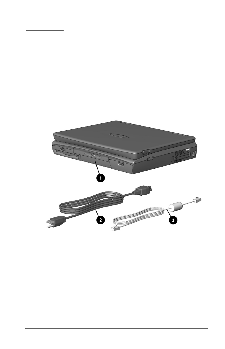
Unpacking the Computer
Contents of the Computer Box
You should have the following items in the packing box:
1 Computer (includes battery pack already installed)
2 Power cord
3 Modem cable (with internal modem models)
Items not illustrated vary by model and geographical region:
Owner Registration Card
■
Warranty and service information
■
Printed documentation about the computer
■
Getting Started 1-1
Page 15

Setting Up the Computer
Before you set up the computer for the first time, ensure that
The computer is using AC power.
■
The computer is not docked in a docking station.
■
WARNING:
!
healthful workstation. Misuse of your personal computer or failure to
establish a safe and comfortable workstation could result in
discomfort or serious injury. Consult your
more information.
It is in your best interest to set up a comfortable and
Safety &Comfort Guide
Charging the Battery Pack for the First Time
The battery pack begins to charge when the computer is connected
to external power.
Although a new battery pack can be used to power the computer
after receiving a partial charge, Compaq recommends that a new
battery pack be allowed to fully charge before the computer is
disconnected from external power or before the battery pack is
removed from the computer.
A new battery pack fully charges in approximately:
2 hours when the computer is connected to external power and
■
is not being used.
5 hours when the computer is connected to external power and
■
is being used.
for
1-2 Getting Started
Page 16
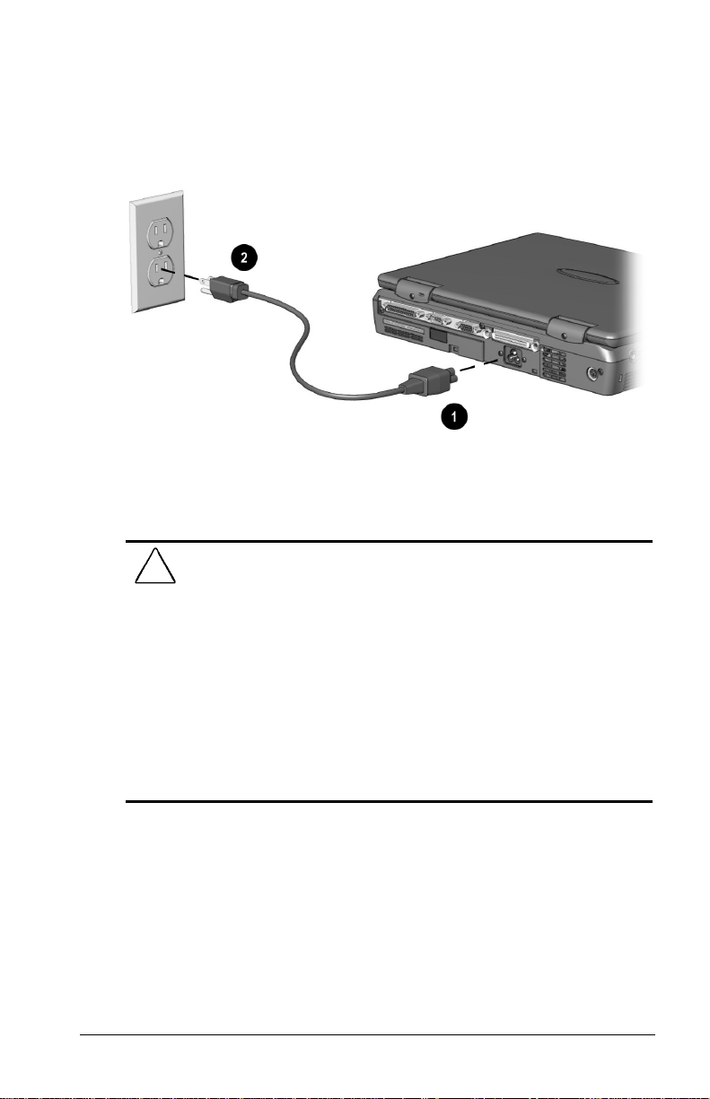
Connecting the Power Cord
1. Place the computer on a flat surface near an electrical outlet.
2. Plug the power cord into the power connector on the rear
panel of the computer 1, then into the electrical outlet 2.
Connecting the Power Cord
WARNING:
!
fire, or damage to the equipment:
Do not disable the power cord grounding plug. The grounding
■
plug is an important safety feature.
Plug the equipment into a grounded (earthed) electrical outlet
■
that is easily accessible at all times.
Disconnect power from the equipment by unplugging the power
■
cord from the electrical outlet.
Do not place anything on power cords or cables. Arrange them so
■
that no one may accidentally step on or trip over them. Do not
pull on a cord or cable. When unplugging from the electrical
outlet, grasp the cord by the plug.
To reduce the risk of personal injury, electric shock,
Getting Started 1-3
Page 17
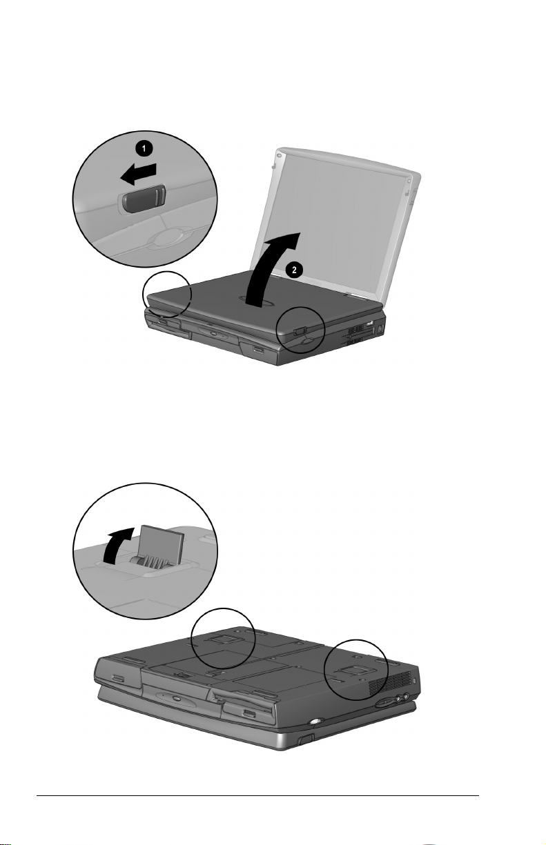
Opening the Computer
Slide forward the display release latches 1 on the left and right
sides of the display, then raise the display 2 to a comfortable
viewing angle.
Opening the Computer
Adjusting the Keyboard
To elevate the back of the keyboard to a more comfortable typing
position, open the tilt feet on the bottom of the computer until they
lock into place. Close to return to the horizontal position.
Lifting Keyboard Tilt Feet
1-4 Getting Started
Page 18
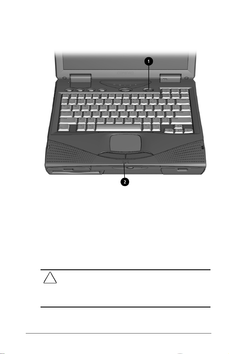
Turning On the Computer
Slide the power switch 1 to turn on the computer. The
power/suspend light 2 indicates the computer is on.
Turning On the Computer
Setting Up the Software
When you begin software setup, online instructions guide you
through the setup process.
IMPORTANT:
the entire process, which may require up to 20 minutes. Make sure
the computer is plugged in for this process to ensure that software
setup is uninterrupted.
After you begin software setup, you must complete
CAUTION:
software drivers are installed:
■
■
To prevent file corruption and ensure the correct
Do not dock the computer in a docking station.
Do not turn off or unplug the computer or remove a drive during
software setup.
Getting Started 1-5
Page 19

Operating the Computer During Setup
To move around the screen while making selections and
■
entering information:
❐
press the
❐
press the cursor (arrow) keys, or
❐
use the touchpad built into the computer keyboard.
To save your selections, press the
■
Tab
key,
key or press one of the
Enter
touchpad buttons below the touchpad on the computer
keyboard.
To restore the screen if it is cleared by the screen saver during
■
a period of keyboard and touchpad inactivity, press th
e
key.
For more information about using the touchpad and touchpad
buttons, refer to Chapter 3, “Using the Keyboard and Touchpad.”
Choosing a Language
If you are prompted to select your language, choose carefully.
Shift
IMPORTANT:
The languages that you do no choose will be deleted
from the computer and cannot be recovered.
1-6 Getting Started
Page 20

Removing the Operating System
A Microsoft Windows operating system is preinstalled on the
computer.
Compaq has enhanced the preinstalled version of this operating
system to provide you with additional software features and
increased computer functionality.
Before deleting the operating system preinstalled on the computer,
please read the following caution:
CAUTION:
■
■
■
Replacing the preinstalled version of this operating system with a
retail version will result in the loss of all enhancements added by
Compaq such as PC Card support and enhanced power
management.
Most preinstalled reference files, such as Help files, are available
only through the Windows interface. If Windows is removed from
the computer, these reference files will become unavailable.
Complete USB support is available only through the Windows
interface. If the operating system preinstalled on the computer is
replaced by an operating system other than this Windows
version, USB support will be decreased.
Restoring Your Operating System and Software
Preinstalled by Compaq
In addition to the preinstalled operating system, Compaq installs
other software to provide additional functionality or
enhancements.If it is necessary to reinstall the operating system
and you do not want to lose these enhancements, it will also be
necessary to reinstall all Compaq software for your computer. Use
the restore software CD that comes with your computer to restore
software on your hard drive.
Getting Started 1-7
Page 21

Completing Setup
Compaq recommends that you:
Register the computer.
■
Locate the Compaq online resources, such as the online
■
Reference Guide
Registering the Computer
Be sure to register the computer according to the instructions on
the
Owner Registration Card
Locating Online Resources
and the online
included with the computer.
Safety & Comfort Guide.
For your convenience, all information contained in this
Guide
is available online.
To access the
■
Click Start
❐
Reference Guide
online:
Æ Compaq Information Center Æ
Reference
Reference Guide
or
Click Start Æ Help Æ Contents
❐
or
Click the Compaq Information Center icon on the desktop
❐
To access information on the Internet, go to www.compaq.com.
1-8 Getting Started
Page 22
chapter
2
AKING
T
OMPUTER
C
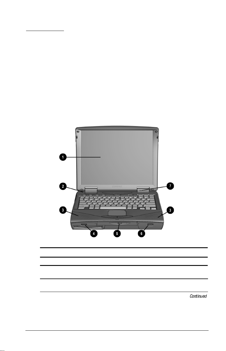
Front Components
A L
OOK AT THE
Front Components
Component Function
Display The computer screen and the
Lid switch Blanks the screen if the display is
hardware in which it is enclosed.
closed and the computer is still on.
Taking A Look At The Computer 2-1
Continued
Page 23

Front Components
Continued
Component Function
Stereo speakers Built-in speakers for high-quality
MultiBay A multifunction device compartment
Optical Disc Bay Dedicated bay which houses either a
Battery bay Holds the main battery pack in the
Internal microphone Built-in monophonic microphone for
stereo sound and a multimedia sound
system.
that accepts a diskette drive, LS-120
diskette drive, Zip drive, second
battery pack, or second hard drive.
CD-ROM drive or DVD drive. For
those models without a factoryinstalled CD-ROM drive, you can
easily upgrade to a CD-ROM drive or
DVD drive.
computer.
the multimedia sound system.
2-2 Taking A Look At The Compute
Page 24
Left Side Components
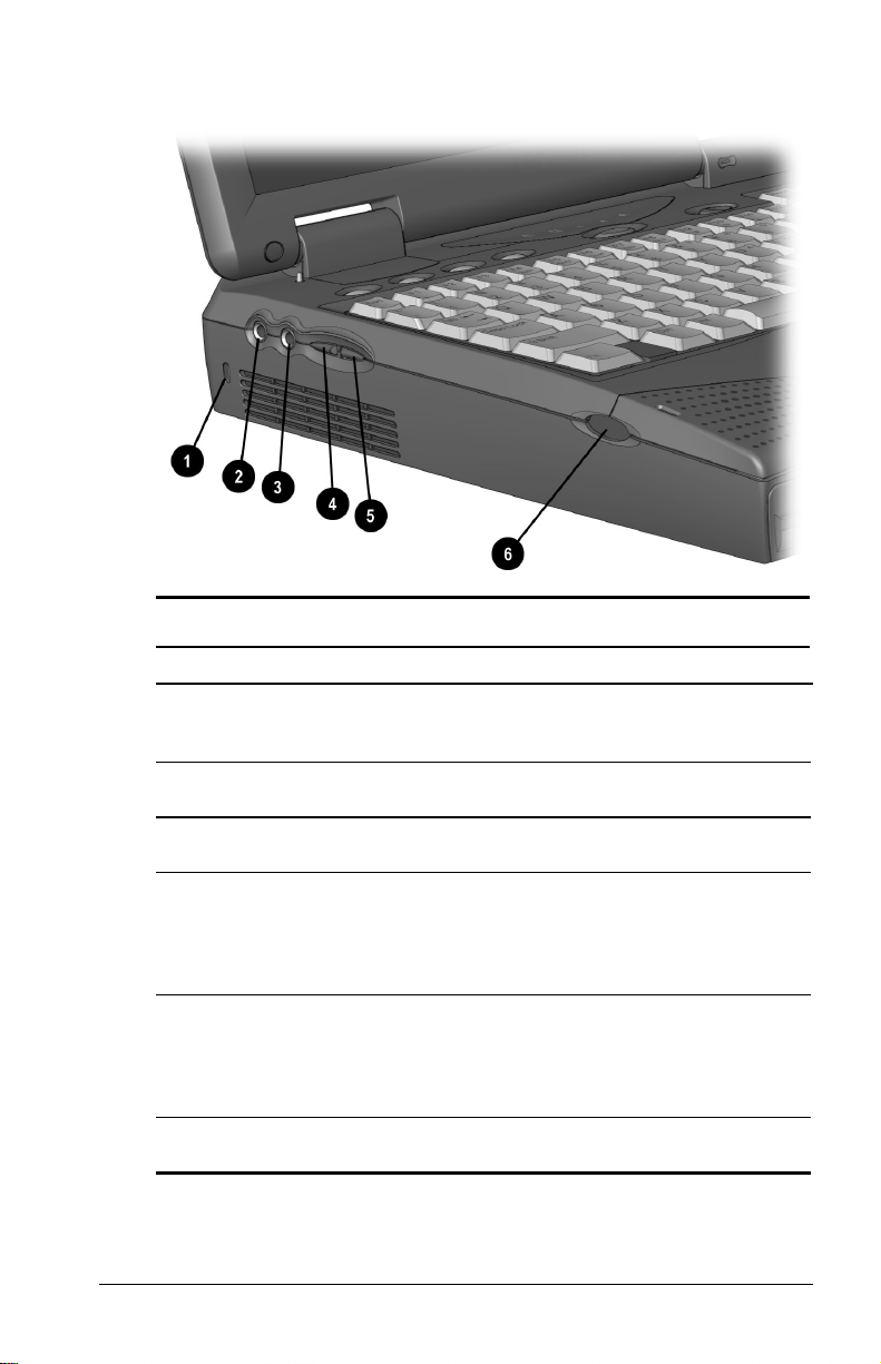
Left Side Components
Component Function
Cable lock Accepts an anti-theft cable that
Speaker/headphone line-
out jack
Microphone line-in jack Connects an external mono
Volume control (up) Increases volume to the built-in
Volume control (down) Decreases volume to the built-in
Base reflex speaker port Allows airflow to and from the internal
secures the computer to a fixed
object.
Connects stereo speakers,
headphones, or headset.
microphone.
speakers, to external speakers, or to
headphones plugged into the stereo
speaker/headphone jack on the
computer.
speakers, to external speakers, or to
headphones plugged into the stereo
speaker/headphone jack on the
computer.
stereo speakers.
Taking A Look At The Compute 2-3
Page 25
Right Side Components
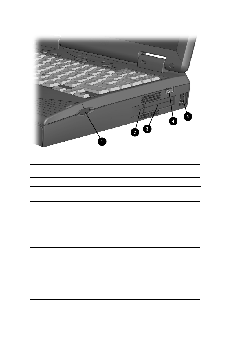
Right Side Components
Component Function
Base reflex speaker port Allows airflow to and from the internal
PC Card eject button Ejects PC Cards from the PC Card
PC Card slots Slots that support Type II or Type III
USB connector A connector which allows you to
RJ11 Used for connecting a standard
stereo speakers.
slots.
PC Cards, such as modem, hard
drive, or network cards. These slots
accept 16-bit PC Cards as well as
32-bit PC Cards.
attach Universal Serial Bus (USB)
devices such as a keyboard or
mouse, or a camera for video
conferencing.
telephone cable to the computer. For
internal modem models only.
2-4 Taking A Look At The Compute
Page 26
Rear Components
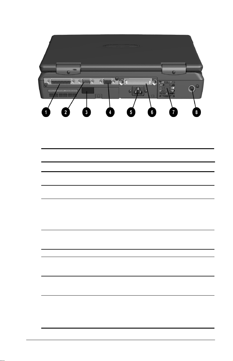
Rear Components
Component Function
Parallel connector Connects an optional parallel device
Serial connector Connects an optional external serial
Infrared port Allows wireless communications
External monitor
connector
AC power connector Connects to external (AC) power.
Docking connector A 176-pin expansion bus connector
Cooling fan Regulates the temperature of the
Keyboard/mouse
connector
such as a printer.
device such as a mouse or printer.
between the computer and another
infrared-equipped device using an
infrared light beam. Available on
specific models.
Connects an optional external
display, such as an external CRT
monitor.
that connects the computer to the
optional convenience base.
computer and its internal
components.
Connects an optional full-sized
keyboard and/or PS/2 compatible
mouse. This Y connector allows
simultaneous connection of mouse
and keyboard.
Taking A Look At The Compute 2-5
Page 27
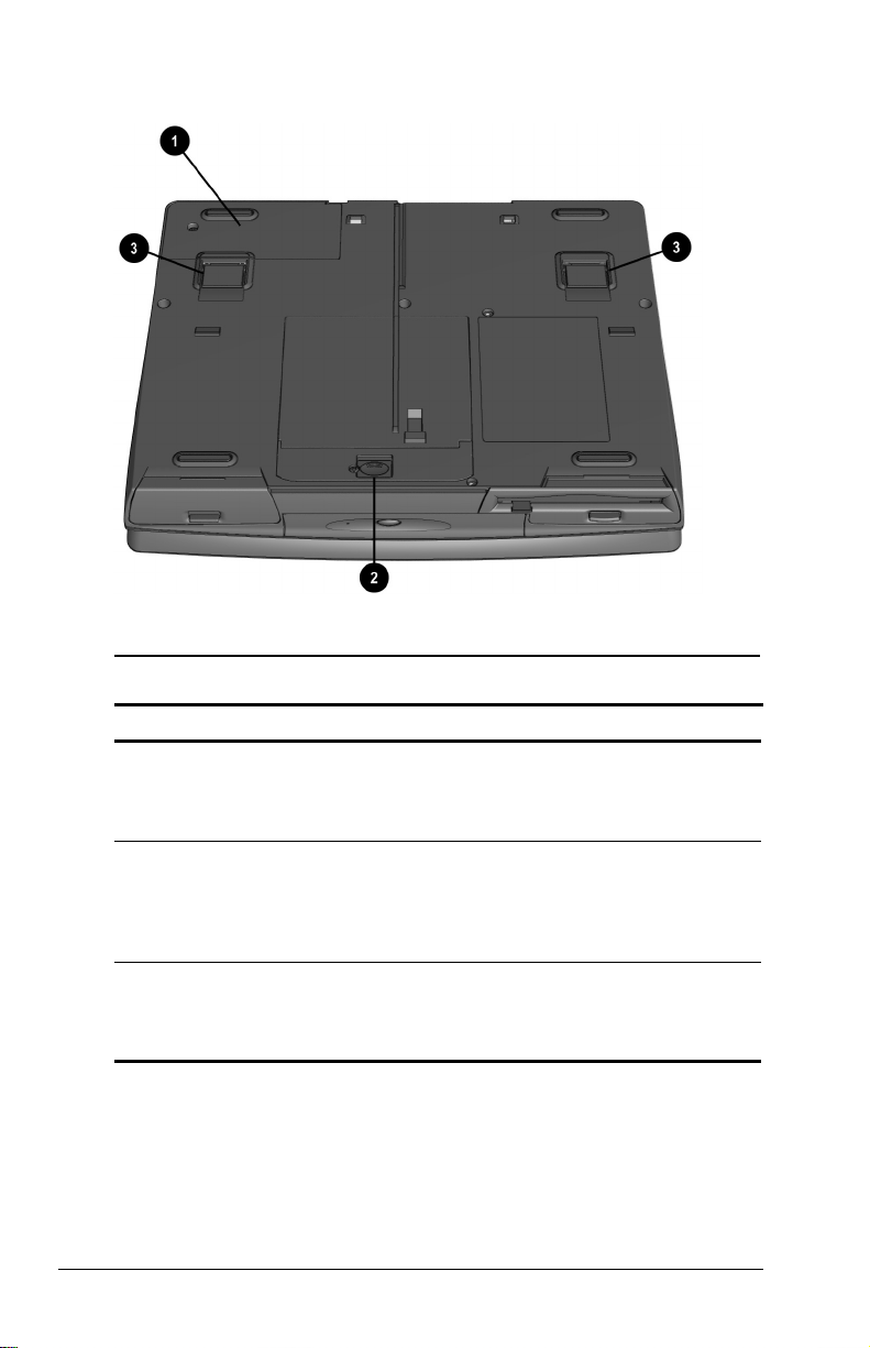
Bottom Components
Bottom Components
Component Function
Modem compartment Provides access to the internal
Hard drive compartment Provides access to the internal hard
Tilt feet Retractable feet on the bottom of the
modem. The modem is available on
selected models and as an option for
other models.
drive. A security screw prevents
unauthorized access to the hard
drive. Use a standard screwdriver to
remove the screw.
computer that open and lock into
place in order to angle the keyboard
to a more comfortable position.
2-6 Taking A Look At The Compute
Page 28
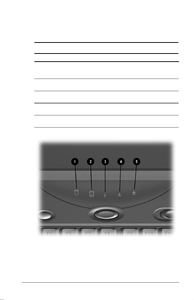
Status Indicator Lights
There are five lights located above the keyboard which indicate
system operations and status. These include:
Status Indicator Lights
Light Function
Hard drive/ CD-ROM
drive access indicator
Diskette drive access
indicator
Num Lock Turns on when the embedded
Caps Lock Turns on when the Caps Lock
Scroll Lock Turns on when the Scroll Lock key is
Turns on when the hard drive,
optional CD-ROM drive, or optional
DVD drive is accessed.
Turns on when a device in the
MultiBay is accessed.
numeric keypad is active.
function is on.
on.
Taking A Look At The Compute 2-7
Page 29
chapter
3
SING THE KEYBOARD AND
U
OUCHPAD
T
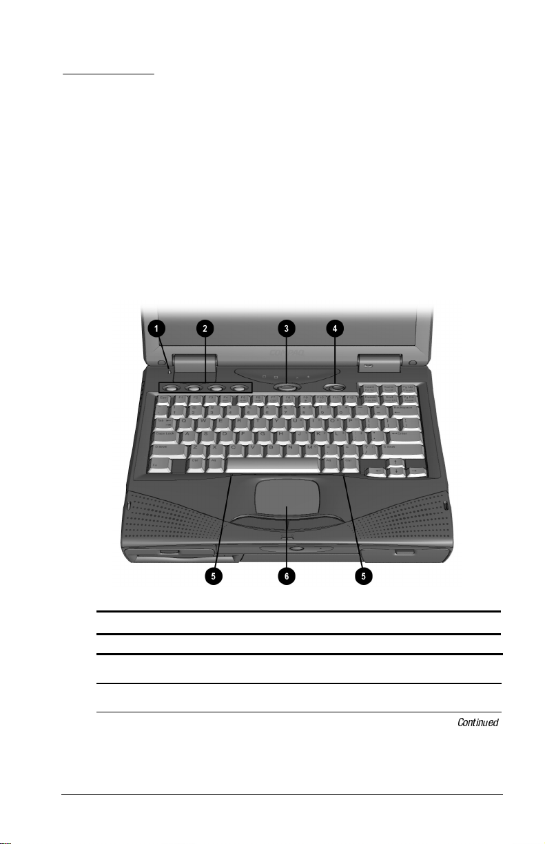
Keyboard Components
Keyboard Components
Component Function
Lid switch
Programmable keys
Blanks the screen if the display is
closed and the computer is still on.
Assign and launch frequently used
applications and documents.
Using The Keyboard And Touchpad 3-1
Continued
Page 30

Keyboard Components
Continued
Component Function
Suspend button Initiates and exits Suspend. Turns on
the computer if it is in Suspend.
When used with the Fn key on the
computer, the Suspend button
initiates Hibernation.
Power switch Slides to turn the computer on or off.
While working in Windows, click
Start, Shut Down to exit the operating
system and turn off the computer.
Keyboard releases Allows access underneath the
keyboard for installing memory
expansion boards in the memory
expansion slot, or a CD-ROM/DVD
drive in the Optical Disc Bay.
Touchpad Functions as an integrated pointing
device.
3-2 Using The Keyboard And Touchpad
Page 31
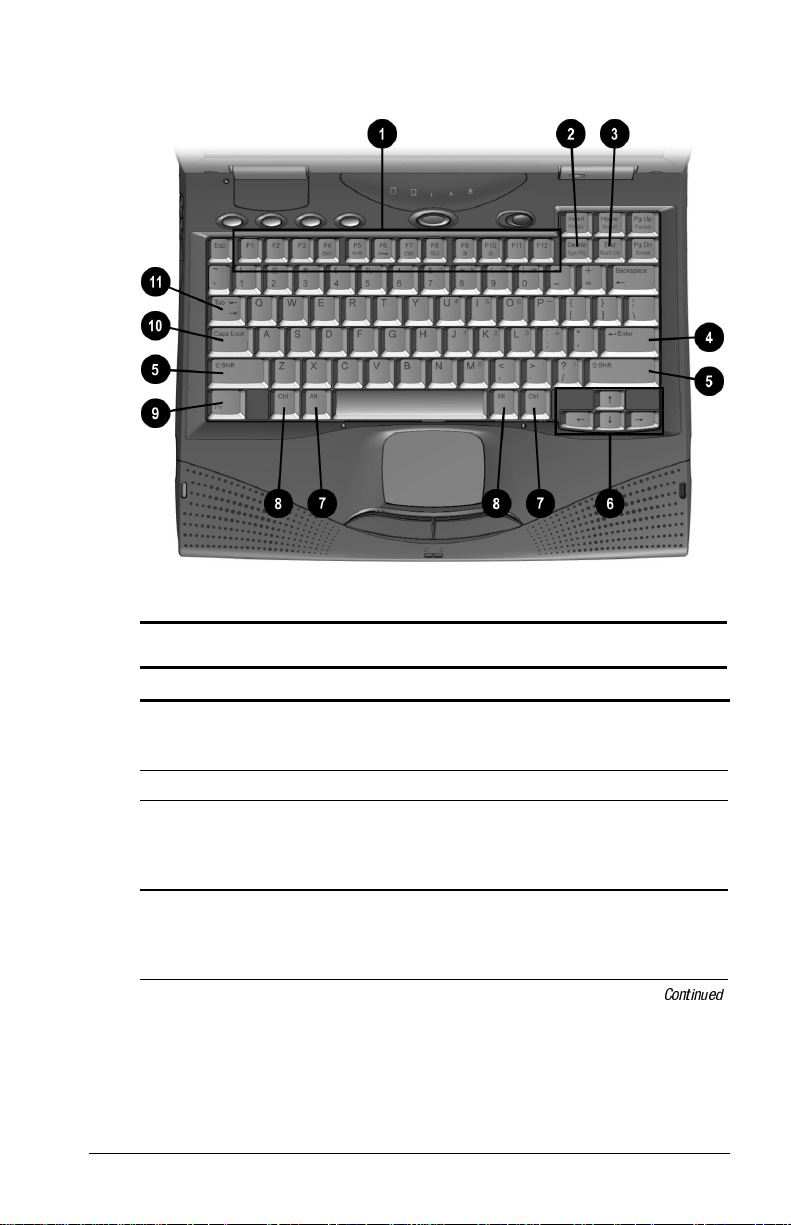
Special Keys
Special Keys
Key (s) Function
Function keys Enter various commands in a
program, depending on the program
being used.
Delete key Deletes characters or selected text.
Num Lock key Activates the embedded numeric
keypad, a section of the keyboard
used for numeric functions, by
pressing the Fn + Num Lock keys.
Enter key Signals the end of input or the end of
a paragraph. To complete a
command you must type or select the
command then press the Enter key.
Using The Keyboard And Touchpad 3-3
Continued
Page 32

Special Keys
Continued
Key (s) Function
Shift keys Toggle between uppercase character
typing and lowercase character
typing. The Shift key can also be
used in combination with the
Function keys for various commands.
Cursor keys Move cursor left, right, up, and down.
Alt keys Enter commands when used in
combination with other keys enters
commands. For example, to switch
between open applications Microsoft
Windows, press Alt+Tab. To close an
application, press Alt+F4.
Ctrl keys Used with other keys to enter
commands.
¡
Fn key Used in conjunction with function
keys to form hotkey combinations
which simplify special computer
operations. The special hotkey
features are activated by pressing the
Fn key and the function key.
¢
Caps Lock key Shifts the alphabetical characters on
the keyboard into uppercase (capital)
when on.
Tab key Keyboard function key that moves
;
the cursor to the next tab stop to the
right.
3-4 Using The Keyboard And Touchpad
Page 33

Using Hotkeys
Hotkeys are keys that simplify the performance of special
computer operations. The special hotkey functions are activated
by pressing the Fn key and the associated function key. The
function keys work as normally defined by application software
when they are not used in conjunction with the Fn key.
Hotkey Quick Reference
Return to
Function Hotkeys
Moves the Hotkey popup window
location.
Switches displays—Toggles
between computer display,
external monitor display, and both
displays at the same time.
Adjusts Speaker volume—Controls
system warning beeps. To
increase volume, press Fn+F5,
then the right arrow key. To
decrease volume, press Fn+F5,
then the left arrow key. Adjusts
system beeps only.
Sets QuickLock/QuickBlank—
disables the keyboard and mouse,
and clears the display. See
Chapter 13 for more information on
Quick Controls.
Sets Battery Conservation—
adjusts the level of battery power
used by the computer. See
Chapter 5 for more information on
power conservation.
Displays the battery gauge—shows
the amount of power remaining in
all system batteries. For more
information on using the battery
gauge, see Chapter 4.
Fn + F1 Fn + F1
Fn+F4 Fn+F4
Fn+F5 Fn+F5
Fn+F6 Enter password
Fn+F7 Fn+F7
Fn+F8 Fn+F8
Original State
Continued
Using The Keyboard And Touchpad 3-5
Page 34

Hotkey Quick Reference
Continued
Return to
Function Hotkeys
Adjusts display contrast. Not
applicable on active matrix
displays.
Adjusts display brightness. Fn+F10 Fn+F10
Enables and disables the
embedded numeric keypad. See
“Embedded Numeric Keypad”, in
this chapter.
Initiates Hibernation (Windows 95
and Windows NT only). See
Chapter 5 for more information on
using Hibernation.
Initiates Text-stretch function,
which stretches the image so that
more of the screen is filled
(functions optimally on display
panels less than 13 inches).
Fn+F9 Fn+F9
Fn+Num Lk Fn+Num Lk
Fn+Suspend Suspend
Fn + T Fn + T
Original State
IMPORTANT:
Popup windows associated with the hotkeys display
correctly only from within applications that support the popup
video mode. If a popup does not display correctly, exit the
application and press the hotkeys again to invoke the popup
window.
3-6 Using The Keyboard And Touchpad
Page 35

Embedded Numeric Keypad
The embedded numeric keypad is a section of the computer
keyboard that converts to a numeric keypad when the number lock
function is enabled.
Embedded Numeric Keypad
Press the
■
Fn+Num Lk
Enable the embedded numeric keypad (Num Lk light
hotkeys to:
turns on).
Disable the embedded numeric keypad (Num Lk light
■
turns off).
With the number lock function on (enabled):
Press Fn to type lowercase letters.
■
■
Press
Fn+Shift
to type uppercase letters.
Using The Keyboard And Touchpad 3-7
Page 36

User Programmable Keys
You can set the four user-programmable keys to bring up a
document or emulate the Microsoft Windows and Application
Logo Keys.
Programmable Keys
By assigning schemes to the programmable keys, you can create
multiple sets of key assignments tailored to your own needs or to
accommodate more than one user.
To assign the programmable keys and create schemes, see
"Assigning the User-Programmable Keys" in this chapter.
3-8 Using The Keyboard And Touchpad
Page 37

Assigning the User-Programmable Keys
To assign or reassign a programmable key:
1. Access the Programmable Keys utility by clicking Start Æ
Settings Æ Control Panel Æ Keyboard Æ Programmable
Keys.
2. Select the current scheme programmable key you wish to
assign or reassign by clicking its button in the Key
Assignments group box.
NOTE:
in the Show Advanced Options check box. This changes the
Assign button to the Browse button. By clicking the Browse
button, you can access all applications on your computer. To
emulate one of the Microsoft Windows and Application Logo
Keys, select the appropriate file from the Program
Files\Compaq\Programmable keys\Default directory.
3. Click the Assign button. A dialog box appears showing a list
of programs or documents from the Programs menu.
4. Highlight the desired application and click OK. The icon and
program name you select appear beside the programmable
key's radio button.
5. Click OK to exit the utility. When you press the
programmable key you have just assigned, your application
and/or document appears on screen.
To access a larger number of programs, place a check
Using The Keyboard And Touchpad 3-9
Page 38

Unassigning the User-Programmable Keys
1. To remove a programmable key assignment:
2. Access the Programmable Keys utility by clicking Start
Settings Æ Control Panel Æ Keyboard Æ Programmable
Keys.
3. Select the programmable key you wish to unassign by clicking
the appropriate radio button in the Key Assignments group
box.
To unassign keys in other than the current scheme, place
NOTE:
a check in the Show Advanced Options checkbox and select a
different scheme. If you have never created a scheme, the
Default scheme will be the only choice.
4. Click the Assign button, then select Unassigned from the list.
The icon and program name previously assigned to the key
will be removed.
When the Show Advanced Options box is checked, you
NOTE:
can unassign a programmable key by clicking the Browse
button and selecting the file 'Unassigned' from the Program
Files\Compaq\Programmable keys\Default directory.
5. Click OK to exit the utility.
Adding Schemes
To add a new scheme:
1. Access the Programmable Keys utility by clicking Start
Settings Æ Control Panel Æ Keyboard Æ Programmable
Keys.
2. Ensure that the Show Advanced Options check box is
checked.
3. Click the Add button.
4. Type a name for your new scheme in the popup dialog box
that appears.
5. Make your programmable key assignments.
6. Click OK to exit the utility.
Æ
Æ
3-10 Using The Keyboard And Touchpad
Page 39

Removing Schemes
To remove a scheme:
1. Access the Programmable Keys utility by clicking Start Æ
Settings Æ Control Panel Æ Keyboard Æ Programmable
Keys.
2. Ensure that the Show Advanced Options checkbox is checked.
3. Select the scheme in the Scheme box that you want to delete.
To view a different scheme, select a scheme from the dropdown list.
NOTE:
The Default scheme is not removable.
4. Click the Remove button.
5. Click OK to exit the utility.
Showing the Key Assignments in the System Tray
One convenient way to see your user-programmable key
assignments is to view them in a popup window that you activate
from an icon in the system tray. To enable the icon:
1. Access the Programmable Keys utility by clicking Start Æ
Settings Æ Control Panel Æ Keyboard Æ Programmable
Keys.
2. Check mark the Show Key Assignments in the System Tray
checkbox.
3. Click OK to exit the utility.
4. An icon appears in the system tray. To view the popup
window, click the icon.
NOTE:
The icon remains in the system tray until you disable it
by unchecking the Show key assignments in the System Tray
checkbox or by right-clicking the icon and choosing Exit from
the menu.
Using The Keyboard And Touchpad 3-11
Page 40

Using the Touchpad
To operate the touchpad, move your finger across the
touchpad surface
and right buttons 3 below the touchpad to select items, much like
using the left and right mouse buttons.
1 to control cursor movement. Press the left 2
Touchpad and Touchpad Buttons
You can also single - and double-tap the touchpad to select and
activate items, as well as use the touchpad to drag objects across
the screen.
To customize the touchpad functions, click Start Æ Settings Æ
Control Panel Æ double-click Mouse.
3-12 Using The Keyboard And Touchpad
Page 41

Customizing the Touchpad Controls
Access the Mouse utility by clicking Start Æ Settings Æ Control
Panel Æ double-click Mouse Æ. Then you may:
Customize the way the touchpad controls the pointer.
■
Control the pointer motion.
■
Cleaning the Touchpad
To clean the touchpad:
1. Turn off the computer.
2. Remove the battery pack and disconnect the power cord.
Wipe the touchpad with a clean, dry cloth. To remove stubborn
stains, wipe the touchpad with a damp cloth moistened with a
small amount of dishwashing detergent.
Using The Keyboard And Touchpad 3-13
Page 42

chapter
4
SING BATTERY PACKS
U
Learning About Batteries
The computer accommodates up to two rechargeable battery packs
at one time. Battery packs are supported in the:
Battery bay in the computer (primary battery pack)
■
MultiBay in the computer (secondary battery pack)
■
With the computer turned off, each battery pack will recharge in
less than two hours. With the computer turned on, each battery
pack will recharge in less than five hours.
If two fully charged battery packs are installed, you can remove
one battery while the computer is on without affecting system
operation. With only one battery pack installed, you must turn off
the computer or initiate Hibernation before removing a battery, or
you must connect to external AC power before you remove the
battery pack. For more information on using Hibernation, see
Chapter 5.
When the computer is in Suspend, you must always have a power
source, either a fully charged battery pack or AC power, before
removing a battery pack. For more information on using Suspend,
see Chapter 5.
Using Battery Packs 4-1
Page 43

WARNING:
!
There is a risk of fire and burns if the battery pack is not handled
properly. Do not disassemble, crush, puncture, short external
contacts, or dispose of in fire or water. Do not expose to
temperatures higher than 60qC. Replace only with the Compaq
spare designated for this product.
Your computer contains a Lithium Ion battery pack.
WARNING:
!
disposed of with general household waste. In order to forward them
to recycling or proper disposal, please use the public collection
system or return them to Compaq, your authorized Compaq
Partners, or other agents.
Batteries/battery packs and accumulators should not be
Using a New Battery Pack
You can charge the battery pack in the computer's battery bay or
MultiBay while connected to an external power source or while
docked in the convenience base. You can also charge up to two
battery packs in the optional battery charger.
IMPORTANT:
used for the first time. The battery pack will work without being
fully charged, but the battery gauge will not show an accurate
charge until the battery pack receives its first full charge.
A new battery pack should be fully charged before it is
Charging Battery Packs
Battery packs charge in the following sequence:
1. The primary battery in the computer battery bay
2. A second battery pack in the computer MultiBay
Battery packs are discharged in the reverse order, with the battery
pack in the MultiBay depleted first. See Chapter 2 for bay
locations.
To charge battery packs, follow these steps:
1. With battery pack(s) in the battery bay and/or MultiBay,
connect the power cord to the computer and plug it into an
electrical outlet.
2. Turn on the computer if you want to use it while the battery
packs are charging.
4-2 Using Battery Packs
Page 44

NOTE:
The battery charge light is the right light on the front of the
computer. It turns on (solid) when a battery pack (in the battery
bay or MultiBay) is charging. It turns off when fully charged. It
blinks in a low-battery condition.
When the battery charge light turns off, the battery packs are fully
charged.
Using the Battery Gauge
Press the
hotkeys to show the status of the battery pack(s).
Fn+F8
Two numbered boxes indicate the status of each installed battery
pack.
Battery pack 1—primary battery in the computer battery bay.
■
Battery pack 2—battery in the computer MultiBay.
■
Using the Battery Gauge Hotkeys
Press the right or down arrow key to view the status of the next
battery pack. If a battery pack is not in a bay, the corresponding
bay cannot be selected. Press the left or up arrow key to select the
previous battery pack.
The percentage of battery charge remaining for the selected
battery pack is shown at the bottom of the popup. If the battery
pack is charging, a lightning bolt symbol appears to the right of
the box. If AC power is connected, the power connector is shown.
NOTE:
If you do not press any key for five to seven seconds, the
battery gauge popup will display the average remaining capacity
(percent of charge remaining) for all installed batteries combined.
Using Battery Packs 4-3
Page 45

Ensuring Battery Gauge Accuracy
The built-in battery gauge, which displays the amount of charge
remaining, is precalibrated for accuracy. To ensure continued
battery gauge accuracy and to maximize battery operating time:
Fully charge the battery pack before the first time you use it.
■
Allow the battery pack to completely charge before removing
■
external power from the computer, convenience base, or
battery charger.
If the battery has been out of the computer for two weeks or
■
more, fully recharge the battery pack before using it.
Approximately every 60 days, allow the battery to completely
■
discharge to the low battery condition through normal use
before recharging it.
The various battery gauges available on your system should
NOTE:
be regarded as an approximate indication of remaining battery life.
Use the battery until the first warning is received, even if the
gauge indicates "no power."
Identifying a Low Battery Condition
When a low battery condition is reached, the computer beeps
twice approximately every five minutes, and the battery power
light blinks once per second. When a critical low battery
condition is reached, the computer beeps four times every five
seconds, and the battery light blinks twice per second.
CAUTION:
little battery charge remains. Take immediate action to resolve the
condition.
When you are alerted to a low battery condition, very
When a low battery condition is reached, save your files and
initiate Suspend. You have approximately 5 to 10 minutes to
resolve the low battery condition before the computer enters the
critical low battery condition.
When a critical low battery condition occurs and Hibernation is
enabled, the system initiates Hibernation.
CAUTION:
Hibernation when a critical low battery condition is reached. If
Hibernation is disabled, the computer initiates Suspend until the
battery pack fully discharges. When this occurs, all unsaved
data is lost.
4-4 Using Battery Packs
If Hibernation is disabled, the computer cannot initiate
Page 46

Resolving a Low Battery Condition by Connecting
the Power Cord
1. Connect the small end of the power cord to the AC power
connector.
2. Insert the wall plug of the power cord into an electrical
outlet.
Resolving a Low-Battery Condition with a
Charged Battery Pack
CAUTION:
is on, you can prevent loss of information by initiating Hibernation
before removing the battery pack.
If you are removing the battery pack while the computer
Stop working and save your work immediately.
Press the
Fn + Suspend
buttons to initiate Hibernation.
Remove the discharged battery pack.
Insert a fully charged battery pack.
Exit Hibernation.
Resolving a Low Battery Condition When
No Power Source Is Available
To resolve a low battery condition when no power source is
available, do one of the following:
Initiate Hibernation until a power source is available. This
■
automatically saves all current information in memory to the
hard disk and turns off the computer. When power is available
and the computer is turned on, all information returns to the
screen at the point where Hibernation was initiated.
Save your information, then turn off the computer until a
■
power source is available.
Using Battery Packs 4-5
Page 47
Inserting and Removing Battery Packs
Removing the Battery Pack from the Battery Bay
CAUTION:
Hibernation or connect the computer to external power before
removing the battery.
If this is the only battery pack in the computer, initiate
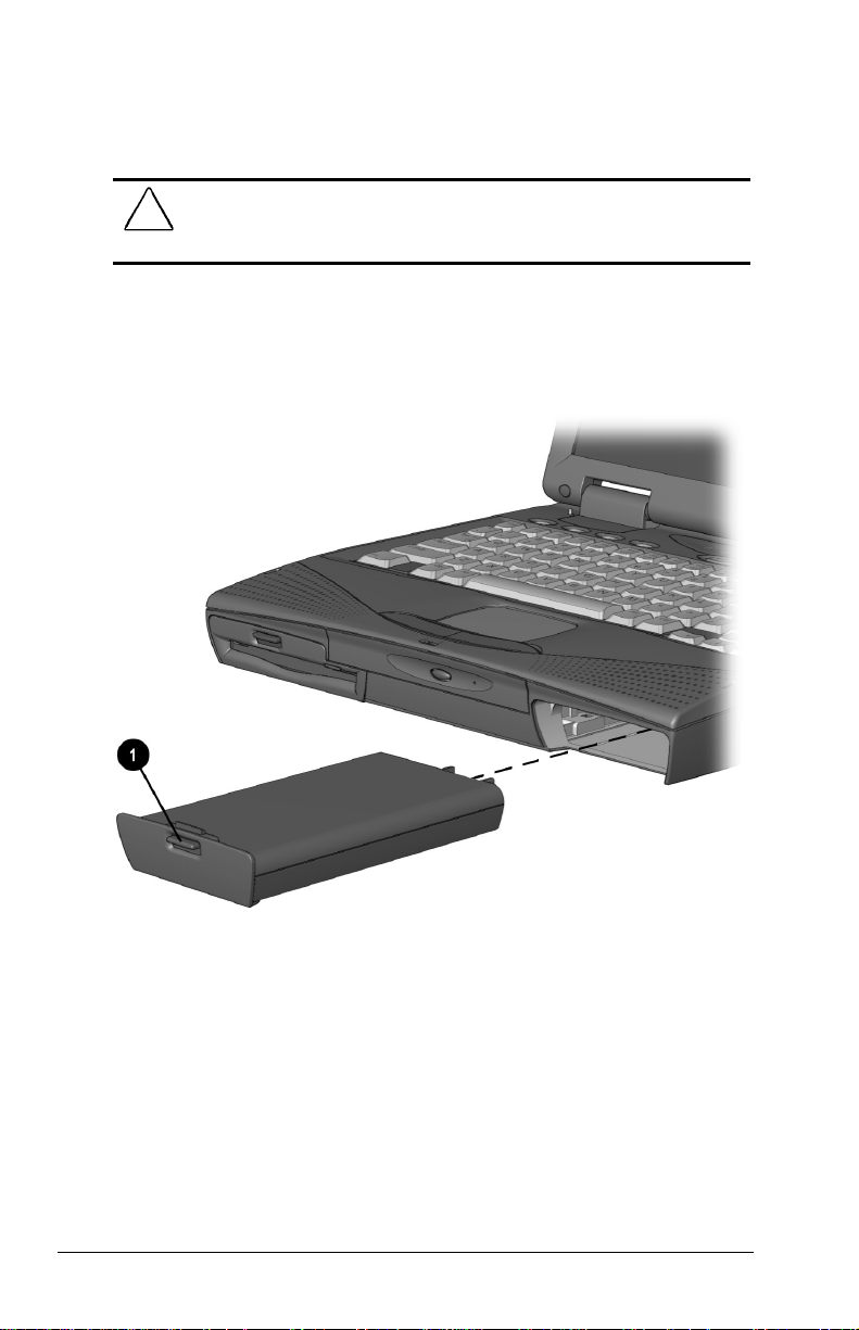
To remove the battery pack from the battery bay:
Pull down the battery release lever n to release the battery pack.
Remove the battery pack from the battery bay.
Removing the Battery Pack from the Battery Bay
4-6 Using Battery Packs
Page 48

Inserting the Battery Pack into the Battery Bay
CAUTION:
Hibernation or connect the computer to external power before
removing the battery.
If this is the only battery pack in the computer, initiate
Insert a battery pack into the battery bay with the large label on
the battery pack facing up and the battery contacts facing in. Push
the battery pack into the battery bay until it is firmly seated.
Inserting the Battery Pack into the Battery Bay
Storing Battery Packs
When storing the computer for more than two weeks, remove the
battery packs and store them separately to reduce the discharge
rate and increase battery life.
Battery packs self-discharge even when they are not being used.
The rate of self-discharge is affected by temperature. To prolong
battery charge, store batteries in a cool, dry place. High
temperatures cause battery packs to lose their charge more
quickly, thus reducing battery life.
Using Battery Packs 4-7
Page 49

The recommended storage temperature range is from 32°F to
104°F (0°C to 40°C). However, batteries can be stored at 32°F to
140°F (0°C to 60°C) for up to 30 days.
CAUTION:
high temperatures for extended periods of time.
To prevent damage to a battery pack, do not expose it to
Maximizing Battery Pack Life
Battery pack operating time varies depending on the system
components, options, and applications used. You can increase
battery operating time by as much as 50 percent by controlling the
energy used by the computer and the energy stored in the battery
pack.
NOTE:
T
he display, processor, and drive components use the
majority of battery power.
To maximize battery pack life, use the following guidelines:
Select the High level of power management (not available
■
under Windows 98). See Chapter 5 for more information on
power management.
Initiate Suspend or Hibernation or turn the computer off when
■
you are not using it.
Reduce the display brightness and select a shorter screen save
■
timeout.
Keep a battery pack in the computer when you are using the
■
computer with external power.
Disconnect external equipment that does not have its own
■
power source. (External equipment connected to the computer
drains the battery pack.)
Exit modem programs when you are not using them.
■
Remove a PC Card when you are not using it.
■
When storing the computer for more than two weeks, remove
■
battery pack(s) and store them separately to reduce the
discharge rate and increase battery life.
4-8 Using Battery Packs
Page 50

Store the battery pack in a cool, dry place when it is not in use.
■
High temperatures cause a battery pack to lose its charge more
quickly and reduce battery pack life. For more information on
storing battery packs, see "Storing Battery Packs" in this
chapter.
Format diskettes while using external power when possible.
■
(Formatting diskettes increases the drain on a battery pack.)
Recycling Used Battery Packs
To find out if the battery pack recycling program is available in
your geographical location, check the worldwide telephone
numbers. If a number for recycling is not listed for your area,
contact your Compaq authorized dealer, reseller, or service
provider.
System Beeps
Beeps with a Blinking Battery Charge Light
When the computer beeps while the battery charge light is
blinking, the computer has entered a low battery condition.
CAUTION:
little battery charge remains. Save your information and take
immediate action to resolve the low battery condition.
If you prefer not to be alerted with system beeps, see “Turning
Beeps On or Off” in this chapter.
When you are alerted of a low battery condition, very
Using Battery Packs 4-9
Page 51

Beeps with a Blinking Power/Suspend Light
When the computer beeps while the Power/Suspend light is
blinking, the computer has initiated Suspend. See Chapter 5 for
more information on using Suspend.
NOTE:
When the computer is in Suspend and a low battery
condition occurs, pressing the power button or suspend button will
NOT exit Suspend. Connect the computer to AC power until a
fully charged battery is available.
If you prefer not to be alerted with system beeps, see “Turning
Beeps On or Off” in this chapter.
Turning Beeps On or Off
Based on the type of beeps you want to turn on or off, do one of
the following:
To enable or disable PC Card beeps, click Control Panel Æ
■
double-click PC Card iconÆGlobal Settings tab, then click to
check or uncheck the Disable PC Card Sound Effects box.
To toggle all system beeps on or off, use the Computer Setup
■
Utility. The following beeps are affected (see Chapter 15 for
more information on using Computer Setup):
Low battery warning beeps
❏
Power-On Self-Test (POST) beeps
❏
Suspend beeps
❏
To disable only low battery warning beeps, click Start Æ
■
Settings Æ Control Panel Æ double-click Power Æ Power
Properties Æ Conservation Settings tab. Then click the
Warning Beeps Off button.
NOTE:
Application-specific beeps must be controlled through the
application software.
4-10 Using Battery Packs
Page 52

chapter
5
OMPUTER POWER AND POWER
C
ANAGEMENT
M
IMPORTANT:
conservation features described in this chapter will be disabled.
For more information on power management under Windows 98,
refer to the section "Using ACPI Power Control" in this chapter.
If you are running Windows 98, several power
Leaving On the Computer
When the computer is left on for extended periods, such as
overnight, you may want to initiate Suspend to conserve power.
The computer should be left in Suspend when it will be
unattended and operating only on battery power. With a fully
charged battery pack, the computer can be left in Suspend for up
to several days, depending on your hardware configuration.
Turning Off the Computer
CAUTION:
and turn off the computer. Failure to properly exit can result in lost
data or corrupted files.
If you are working in DOS or if you experience a severe system
crash, you can use the power switch to turn off the computer, or
press
locked up.
In Windows, use Shut Down to exit the operating system
Ctrl +ALT+Delete
if either the keyboard or the system is
If you plan to store the computer for an extended period, such as
two weeks, you should turn off the computer and remove the
battery pack. This reduces the battery pack's discharge rate and
extends its life.
Computer Power and Power Management 5-1
Page 53

If you use the computer frequently and want "instant-on"
convenience, you do not have to turn off the computer. Simply
initiate Suspend when the computer is not in use. With a fully
charged battery pack, the computer can be left in Suspend up to
several days, depending on your hardware configuration.
If you want to charge a battery pack while you are not using the
computer, connect the computer to external power and turn it off.
Although the battery pack will charge whether the computer is
turned on or off, it takes more than twice as long to charge it with
the computer on.
When external power is not available and battery power is low,
initiate Hibernation by pressing
complete the following steps:
1. Save your information.
2. Exit your applications.
3. Turn off the computer using Windows Shut Down (if you are
in Windows) or by using the power switch (if you are in DOS)
until external power or a fully charged battery pack is
available.
Fn
+
Suspend
buttons, or
Restarting the Computer
There are several methods to restart the computer, depending on
the power state:
From Hibernation
From Suspend
From Windows
5-2 Computer Power and Power Management
Slide the power switch.
Press the suspend button.
Click Shut Down from the Start menu,
then click Restart the Computer.
Page 54

Disconnecting the Computer
from External Power
When the computer does not contain a charged battery pack, save
your work and turn off the computer before disconnecting it from
external power.
When a charged battery pack is in the computer, you do not need
to turn off the computer before disconnecting it from external
power. The computer automatically switches to battery power.
IMPORTANT:
external power for an extended period of time, remove the battery
pack(s). This reduces the discharge rate and extends battery life.
If the computer will be unused and disconnected from
Managing Power
The computer comes equipped with a collection of power
management features that allow you to extend battery operating
time or conserve AC power.
You can use power management to monitor most of the computer
components, such as the hard drive, processor, and display. When
these components are inactive for specified periods of time (called
timeouts), you can use power management settings to shut them
down temporarily. This will conserve battery or AC power.
Most power management settings are located under Power
Properties (Click Start Æ Control Panel Æ double-click Power Æ
Power Properties). These setting options allow you to configure
the way your system uses battery and AC power.
Computer Power and Power Management 5-3
Page 55

Use the following table to view or change power management
settings.
Click This Tab in
If You Want To:
Show Suspend on the Start
menu
Show battery gauge on the
taskbar
Set battery conservation levels;
enable/disable warning beeps;
set timeouts
Select Hibernation settings Hibernation
Enable/disable Energy Saver AC Energy Saver (Windows NT 4.0
Set timeouts for drives when
using battery power or AC
power
Turn off power to the PC Card
slots
Set date and time to exit
suspend; enable/disable
Resume Timer
Display the status of installed
batteries
Power Properties:
Power + Advanced button
Power (Windows 95 only)
Battery Conservation Settings
only)
Disk Drives (Windows 95 only)
PC Card Modems (Windows 95
only)
Resume Timer
Battery Status
5-4 Computer Power and Power Management
Page 56

Using Power Properties
Power Properties allows you to control how AC and battery power
are used in the computer. To access Power Properties, click Start
Control Panel Æ double-click Power Æ Power Properties.
Æ
If You Want To: Click This Tab:
Set battery conservation levels and
enable or disable warning beeps
Select Hibernation settings Hibernation
Display the status of installed batteries Battery Status
The Battery Status tab is a Compaq application that
NOTE:
Battery Conservation
Settings
provides information on the status of each battery. This utility
includes: a picture of each battery, showing where it is installed on
the computer; the life remaining in each battery; and which battery
is currently charging.
Setting the Battery Conservation Level
You can set battery conservation to one of four levels:
■
Medium—The default setting. Balances system performance
and battery operating time.
■
High—Provides maximum battery conservation. Select this
level if you need more battery life and do not mind shorter
timeouts and a dimmer display.
■
None (Drain)—Results in maximum battery drain because
battery conservation is turned off. Recommended only for
discharging the battery pack.
CAUTION:
the computer is in Drain mode. Before selecting this
conservation level, be sure the Hibernation feature has not been
disabled.
■
Custom—Lets you set the timeouts so that the computer
Hibernation does not automatically initiate while
works efficiently in your environment. The default setting
(Medium) is used here until you set your own.
You can set the battery conservation level one of two ways:
Computer Power and Power Management 5-5
Page 57

Setting the Battery Conservation Level with Hotkeys: Choose
■
a preset level of battery conservation by pressing
you select None (Drain), it remains in effect until you change
it.
Using Power Properties: Change the default levels of battery
■
conservation through the Battery Conservation Settings tab in
Power Properties (click Start Æ Control Panel Æ double-click
Power Æ Power Properties). Choose a preset level or
customize your own level. The level you set remains in effect
until you change it.
Fn+
Using Advanced Power Management
In Windows 95, some Windows applications require that
Advanced Power Management (APM) be enabled in order to run
effectively. APM, which is enabled by default on your computer,
automatically reduces power consumption behind the scenes,
saving power while you work. For example, APM turns off the
microprocessor between keystrokes and when your applications
are idle.
Using ACPI Power Control
Windows 98 provides ACPI (Advanced Configuration and Power
Interface), which is a system-wide approach to system and device
power control, as well as thermal management. ACPI enables the
operating system to respond to events and manage power for the
entire system and its devices. It makes the computer more
accessible by reducing boot time and allowing the computer to
wake up automatically. ACPI also incorporates power
management that reduces power consumption of the computer by
turning off the microprocessor and other components when
applications are idle or between keystrokes.
F7
. If
With ACPI, some Compaq power management features such as
power conservation settings in Computer Setup, battery
conservation popup windows, and initiating Hibernation will be
disabled.
For more information on ACPI functions, consult your Microsoft
Windows 98 reference guide.
5-6 Computer Power and Power Management
Page 58

Using Hibernation
Hibernation is a safeguard feature that saves your information
when the computer reaches a low battery condition while it is left
unattended. When your computer hibernates, all the information in
system memory is saved to the hard disk and the power to the
computer is turned off. When you turn on the computer, your
information returns to the screen at the point where Hibernation
initiated. Hibernation behaves like a bookmark, and none of your
information is lost.
When Hibernation is initiated, it creates a file on the hard drive at
least equal in size to the amount of total random access memory
(RAM). If there is not enough space on the hard disk to store the
information, an insufficient disk space message is displayed.
Hibernation will automatically initiate as long as it is not disabled
(turned off) through the software. If you disable Hibernation and
the computer reaches a low battery condition, your unsaved
information will be lost.
CAUTION:
use the computer, the system may not hibernate and your unsaved
information will be lost.
If a low battery condition occurs and you continue to
Enabling Hibernation
If you have disabled Hibernation, you can enable it again through
the Hibernation tab in Power Properties (click Start Æ Control
Panel Æ double-click Power Æ Power Properties). When you
enable Hibernation this way, the system uses a certain amount of
hard disk space necessary for Hibernation to take place.
Initiating Hibernation
Hibernation can be initiated by you or by the system.
When Hibernation occurs, the system:
clears the screen.
■
saves all current information in memory to the hard disk.
■
turns off the computer.
■
Computer Power and Power Management 5-7
Page 59

In Windows 95, you can initiate Hibernation by pressing
Fn + Suspend
button at any time and from within any application.
System-initiated Hibernation takes place under the following
conditions:
when the computer is on and unattended, and a critical low
■
battery condition occurs.
when the computer is in Suspend, and a critical low battery
■
condition occurs.
Exiting Hibernation
To exit hibernation and resume work:
1. Install a fully charged battery pack or connect to an external
power source.
2. Turn on the computer by sliding the power switch.
The computer exits Hibernation. The information that was saved
to the hard disk returns to the screen at the point where
Hibernation was initiated.
You may stop the restoration of information by pressing
NOTE:
Ctrl+Alt+Delete
Ctrl+Alt+Delete
. However, remember that if you use the
function, all unsaved data will be lost.
Disabling Hibernation
To disable Hibernation, click the Hibernation tab in Power
Properties (click Start Æ Control Panel Æ double-click Power
Power Properties) and select
CAUTION:
condition occurs and Hibernation is disabled.
You will lose unsaved information if a low battery
Off
.
Using Suspend
Suspend is a reduced power condition during which most of the
major components (such as the hard drive, processor, and display)
shut down after a period of system inactivity called a timeout.
Suspend can be initiated whether the computer is running on
battery or external power.
Suspend is initiated in one of three ways:
5-8 Computer Power and Power Management
Æ
Page 60

Automatically—when a predefined timeout has been reached.
■
You can define the Suspend timeout period through the
Battery Conservation Settings tab in Power Properties (click
Start Æ Control Panel Æ double-click Power Æ Power
Properties).
Manually—by pressing the Suspend button on the computer.
■
Manually—by clicking Suspend from the Windows Start
■
menu.
With a fully charged battery pack, the computer can be left in
Suspend for up to several days, depending on your hardware
configuration.
When you exit Suspend, your information returns to the screen at
the point where Suspend was initiated. No information is lost.
If the computer is in Suspend and a low battery condition occurs,
the system initiates Hibernation, saves your information to the
hard disk, and turns off your computer. When you install a fully
charged battery pack or connect to an external power source, your
information returns to the screen at the point where Suspend was
initiated. No information is lost.
CAUTION:
battery condition occurs while the computer is in Suspend, your
unsaved information will be lost.
If you disable the Hibernation feature and a critical low
Computer Power and Power Management 5-9
Page 61

Identifying a Suspend Condition
When Suspend initiates, the following occurs:
the computer beeps twice.
■
the screen blanks.
■
the power/suspend light blinks.
■
If a low battery condition occurs while the computer is in
NOTE:
Suspend, the system initiates Hibernation and will not resume
until a power source becomes available.
Initiating Suspend
Suspend can be initiated either by you or by the system.
System-initiated Suspend occurs:
■
after a predetermined period of system inactivity.
❏
during a normal battery condition (not during a low battery
❏
condition).
In Windows 95, when the Medium, High, or Custom level
❏
of battery conservation is used.
You can initiate Suspend at any time by:
■
pressing the Suspend button.
❏
clicking Suspend from the Windows Start menu.
❏
When Suspend is initiated, the computer beeps twice, the screen
blanks, and the power/suspend light blinks.
Exiting Suspend
To exit Suspend, press the suspend button.
When the system exits Suspend:
the computer beeps twice.
■
the power/suspend light turns on.
■
your information returns to the screen.
■
IMPORTANT:
is low or the battery is dead. You must find a new power source
for your computer. When a new power source is connected to the
computer, press the suspend button to return your information to
the screen.
5-10 Computer Power and Power Management
The computer will not exit Suspend if battery power
Page 62

Using Timeouts
Timeouts are specified periods of system or component inactivity.
Timeouts work with battery conservation to conserve power.
When a timeout period has expired, battery conservation shuts
down the system or components in order to save power. For
example, the hard disk idle default timeout is two minutes.
Therefore, if an application does not access information on the
hard disk in less than two minutes, the hard disk shuts down until
it is accessed again.
Timeout values are set using the Battery Conservation Settings or
Hibernation tab in Power Properties (click Start Æ Control Panel
double-click Power Æ Power Properties). Using these utilities,
Æ
you can:
use the preset timeouts provided with the medium (default) or
■
high level of battery conservation.
or
set your own component timeouts in conjunction with the
■
custom level of battery conservation so that the computer
works more efficiently with your applications.
Setting Component Timeouts
If you are running Windows 95, you can set your own timeout
values for individual components of the computer. To set
component timeouts:
1. Access the Power Properties utility by clicking Start Æ
Control Panel Æ double-click Power Æ Power Properties.
2. Click the Battery Conservation Settings tab.
3. Set the Battery Conservation level to Custom.
4. Using the drop-down boxes, select or type a timeout value for
specific components of the computer, such as system idle and
hard disk idle.
5. To save your settings, click OK when you are done. They
become effective immediately and remain in effect until you
change them.
Computer Power and Power Management 5-11
Page 63

Setting the Screen Saver
In Windows 95, the screen save timeout is the amount of time that
the system can be idle before a screen saving utility initiates. For
example, if you want the screen saver to initiate after five minutes
of computer nonuse, set the screen save timeout value to five
minutes. If you want the screen to go blank after the specified
period, select Blank Screen.
To customize the screen save timeout value for your computer:
1. Click Start Æ Settings Æ Control Panel Æ Display icon
Screen Saver tab.
2. Select a screen saver.
3. Click OK.
Æ
5-12 Computer Power and Power Management
Page 64

chapter
6
ORKING WITH REMOVABLE
W
RIVES AND DEVICE BAYS
D
Bay Configuration
The three computer bays support standard as well as optional
devices. Some devices can be hot plugged, while others must be
inserted after the computer has been turned off. The following is a
list of devices supported in all bays, as well as the computer power
state required before inserting the device (see Chapter 2 for bay
locations):
Bay Configuration
Functional Bay Devices Supported Power State
MultiBay Diskette drive On
LS-120 Drive Off
Zip Drive Off
Second battery pack On
Second hard drive Off
Optical Disc Bay CD-ROM drive Off
DVD drive Off
Battery Bay Battery pack On
Working with Removable Drives and Device Bays 6-1
Page 65

Caring for Removable Drives
Removable drives such as the hard drive, the CD-ROM or DVD
drive, diskette drive, LS-120 drive, and Zip Drive are fragile
computer components that must be handled with care.
CAUTION:
or to prevent loss of information, observe the following precautions.
Back up the information on a hard drive before removing it.
■
To prevent damage to the computer or removable drive
Failure to back up the hard drive can result in loss of
information if the drive is handled improperly.
If there is a diskette, compact disc, or digital video disc in a
■
drive, remove it prior to removing the drive from the
computer.
Do not remove a CD-ROM or DVD drive with the tray
■
extended. Before removing the drive, push the drive tray into
the drive.
Ensure that you are discharged of static electricity before
■
handling a removable drive. Electrostatic discharge can
damage electronic components. When handling a removable
drive, always grasp the outer case and avoid touching the
connectors.
Do not use force when inserting a drive into a bay. Excessive
■
force may damage the connectors.
Carefully handle the removable drive. DO NOT DROP IT.
■
Avoid exposing a hard drive to products with magnetic fields
■
such as video and audio tape erasure products, monitors, and
speakers.
Do not spray the drive with cleaners or expose it to liquids.
■
Avoid exposing the drive to temperature extremes.
■
6-2 Working with Removable Drives and Device Bays
Page 66

Using the Diskette Drive
Selecting Diskettes
The diskette drive, which is housed in the computer MultiBay,
reads and writes information onto a 3.5-inch diskette.
The MultiBay also accommodates an optional LS-120 Drive or
Zip Drive.
Each drive accepts the following diskettes:
Type of Drive Diskettes accepted
Diskette Drive 1.44-MB high-density (HD)
720-Kbyte double-density (DD)
1.2-MB Japanese format
LS-120 Drive 120-MB SuperDisk
1.44-MB high-density (HD)
720-Kbyte double-density (DD)
Zip Drive 100-MB Zip Disk
Inserting a Diskette
Hold the diskette by the edge where the label is affixed. Insert the
diskette, label facing up, into the diskette drive until it clicks into
place.
If the diskette is inserted correctly, it drops into position inside the
drive and the diskette drive button pops out.
Removing a Diskette
To remove a diskette, push the diskette drive button. After the
diskette is ejected, gently pull it from the drive.
Working with Removable Drives and Device Bays 6-3
Page 67

Using the CD-ROM Drive
Inserting a Compact Disc into the CD-ROM Drive
1. Turn on the computer.
2. Press the eject button on the bezel of the CD-ROM drive to
release the CD loading tray.
3. Slowly pull out the CD loading tray until it is fully extended.
4. Remove the CD from its protective case and place it in the CD
loading tray, label side up. Handle the CD by the edges, not by
the flat surfaces.
5. Push lightly on the bezel of the CD loading tray to close it.
The light on the CD-ROM drive turns on while the CD is checked
and the table of contents is being read. The light turns off when
the CD-ROM drive is ready to receive commands.
Removing a Compact Disc from the CD-ROM Drive
1. Turn on the computer.
2. Press the eject button on the front panel to open the CD
loading tray.
3. Slowly pull out the CD loading tray until it is fully extended.
4. Remove the CD from the tray. Handle the CD by the edges,
not by the flat surfaces.
5. Place the CD in its protective case.
6. Gently push the front panel of the CD loading tray to close it.
6-4 Working with Removable Drives and Device Bays
Page 68

Manually Ejecting a Compact Disc
If a compact disc becomes lodged in the CD-ROM drive, remove
it by using the following steps:
1. Insert a paper clip or similar thin metal rod into the manual
release hole on the front bezel of the CD-ROM drive. Press
firmly.
2. Slowly pull the tray out from the drive until it is fully
extended.
3. Remove the compact disc.
Manually ejecting a compact disc
Using the DVD-Rom Drive
The standard configuration of the DVD-ROM drive is for
enhanced data storage. To take full advantage of multimedia
features, you will need to purchase the DVD-to-Go PC Card from
Margi Systems. This card enables you to play DVD encoded files
and MPEG-2 videos with broadcast quality, full screen, full
motion video. It will also enhance sound with synchronized Dolby
Digital Surround Sound. For more information on the DVD-toGo-PC Card, visit the Margi Systems web site at
http://www.margi.com.
Working with Removable Drives and Device Bays 6-5
Page 69

MultiBay Devices
The MultiBay supports a diskette drive, LS-120 drive, Zip Drive,
second battery pack, or second hard drive.
CAUTION:
Refer to "Bay Configuration" in this chapter to determine if the
computer must be on or off before inserting or removing MultiBay
devices. This helps protect the computer or the device from
damage, or data loss.
Electrostatic discharge can damage electronic components. Before
touching the hard drive, ensure that you are discharged of static
electricity by touching a grounded metal object.
Some but not all MultiBay devices can be hot plugged.
Inserting Devices into the MultiBay
To install a supported device into the computer MultiBay:
1. If your device is not hot-pluggable, turn off the computer.
2. Insert the device into the MultiBay until it locks into place.
IMPORTANT:
drive adapter before it is inserted into the MultiBay.
A second hard drive must be installed into a hard
Inserting a MultiBay Device
6-6 Working with Removable Drives and Device Bays
Page 70

Removing Devices from the MultiBay
To remove a supported device from the computer MultiBay:
1. If your device is not hot-pluggable, turn off the computer.
2. Press the MultiBay release lever to release the device.
IMPORTANT:
A second hard drive must be installed in a hard
drive adapter before it is inserted into the MultiBay. When
removing a second hard drive, first remove the adapter from
the MultiBay, then remove the hard drive from the adapter.
3. Remove the device
Removing a MultiBay Device
Using a Second Hard Drive
The computer is designed to use up to two hard drives: one in the
computer and one in the computer MultiBay.
NOTE:
The unit will not boot from the second hard drive. The unit
will only boot from the internal hard drive.
Working with Removable Drives and Device Bays 6-7
Page 71

chapter
7
SING THE INTERNAL MODEM
U
Modem Overview
The internal modem comes built into some models and is an
option for other models. It provides data communications and fax
functionality for applications running under Windows 95,
Windows 98, and Window NT 4.0. Preloaded software drivers are
required for modem operation and allow the modem to easily
communicate with software applications.
The internal modem supports standard analog modem
communication protocols (for speeds up to 33.6 Kbps) as well as
up to the ITU-compatible V.90 and industry standard K56flex
56K protocals for higher speeds.
IMPORTANT:
downloads only from V.90 K56flex compliant digital sources.
Maximum achievable download transmission rates are currently
unknown, may not reach 56Kbps, and will vary with line
conditions.
Without having to make hardware changes, the modem may be
configured for operation in a variety of countries. An integrated
RJ-11 jack provides for simple connectivity to phone cables. If
accidentally plugged into a digital PBX phone outlet, the modem
automatically protects itself from excessive current until it is
plugged into an analog phone jack.
The V.90 and K56flex protocols allow faster
Using the Internal Modem 7-1
Page 72

Connecting the Modem
To connect the modem to a standard telephone wall jack:
WARNING:
!
that the modem line is disconnected from the telephone network
when opening the equipments enclosure.
1. Connect one end of the modem cable into the RJ-11 jack on
the right side of the computer.
IMPORTANT:
(Direct AccessArrangement) that supports multiple countries.
However, some countries may require an adapter to connect
the modem to the telephone wall jack.
The modem cable includes EMI suppression circuitry near the
end of the computer. For continued EMI emissions
compliance, plug that end of the cable into the computer.
2. Plug the opposite end of the cable into a standard telephone
wall jack.
IMPORTANT:
standard telephone jacks but are not compatible with analog
devices such as modems. Be sure the modem cable is
connected to a regular analog phone line. Plugging the modem
into a digital line will result in no dial tone and is not
recommended. The modem includes protective circuitry
against the digital lines producing excess current.
To reduce the risk of electrical shock, always ensure
The internal modem uses a universal DAA
Wall jacks for digital PBX systems may resemble
Understanding How the Modem Works
The modem serves two major functions:
The data communications function allows your computer to
■
send information to and receive information from an online
service, a host mainframe computer that provides electronic
mail, and even other personal computers.
The facsimile function allows your computer to both send and
■
receive text and images from facsimile (fax) machines or other
computers.
7-2 Using the Internal Modem
Page 73

After setting up your software, you are ready to start using your
modem. In most cases, if you are using communications and fax
software, the modem will be controlled by the software and you
will not need to use the AT command set. Simply select the
internal modem as the preferred communication device in your
application.
NOTE:
The maximum connection speed on a call is determined by
the speed of the slowest modem on the connection. Your modem
will automatically negotiate the fastest possible speed with the
remote modem.
Changing the Country Selection
The internal modem is configured to meet operating approval in
the country where you purchased your computer. If the modem is
used in other countries during travel, the country selection setting
for the modem needs to change to meet the telecommunications
regulations for that country.
The Country Select Application (CSA) lists all of the countries for
which the modem contains configuration information. To confirm
that the modem has been approved for use by the
telecommunications agency in the desired country, check the
approvals label on the bottom of the computer. Or, for the most
up-to-date information, refer to the Compaq Internet website at
www.compaq.com.
NOTE:
The internal modem supports specific countries that are
included in the selection list.
If you are running Windows 95 or Windows 98:
1. Click Start Æ Settings Æ Control Panel Æ double-click the
System icon.
2. Click the Device Manager tab.
3. Double-click modem icon, then double-click your modem.
4. Click the Country Setting for Modem tab, then select the
country from the List of Countries.
5. If you are traveling, click the Change Country button. While
traveling, you will be asked to confirm this setting at each
reboot. If you have permanently relocated to the country, click
the Home Country button, then click the Change Country
button.
6. Click Yes to confirm your country selection.
7. Click Yes to restart your computer.
Using the Internal Modem 7-3
Page 74

If you are running Windows NT:
1. Click Start Æ Settings Æ Control Panel Æ double-click the
CSA Control Panel
2. Select the country from the List of Countries.
3. If you are traveling, click the Change Country button. While
traveling, you will be asked to confirm this setting at each
reboot. If you have permanently relocated to the country, click
the Home Country button, then click the Change Country
button.
4. Click Yes to confirm.
5. Click Yes to restart your computer.
When the Home Country and Current Country selections in
NOTE:
the CSA do not match, you will be prompted each time the system
restarts to confirm that the Country setting still reflects where the
modem is being operated at this time. To disable these reminders,
change the Home Country selection in the CSA to match the
Current Country. The Current Country setting should always be
set to the country in which the modem is currently being operated.
Software Overview
You need communications software to operate the modem. Such
software issues commands to the modem, including modem
connection speed, the number of rings before answering the
telephone, listening for a dial tone, and dialing a phone number.
For information on controlling the phone dialing sequence, refer
to “Dial Modifiers”. The internal modem, for example, includes
the ability to wait for a “go ahead tone” after dialing a credit card
number as part of the dialing sequence. To do this, add a $ symbol
at the appropriate point in the phone number string.
There is a wide range of communications software available that
can be used with this modem for tasks such as accessing your
computer from a remote location. Contact your Compaq
authorized dealer, reseller, or service provider for a complete list
of communications software applications.
IMPORTANT:
occurs while your are using the modem with communications
software, the modem will disconnect. Exit Hibernation or resolve
the low battery condition, then restart the communications
software to restore the original modem settings.
7-4 Using the Internal Modem
If Hibernation initiates or a low battery condition
Page 75

Modem Defaults
Some data or fax communications software prompts you for
specific information about the model of modem you are using. In
this case, if the internal modem is not available as a choice, select
one of the following modems: Compaq Modem or Hayes
Compatible.
NOTE:
Choosing another modem does not affect the actual
connection speed of the modem.
Use the following information if required for modem setup:
Modem Defaults
COM port setting COM2
DCE Speed 56 Kbps
DTE Speed 115.2 Kbps
Data Format Databits - 8
Data Format Parity - N
Data F ormat Stopbits - 1
Dial Command ATDT
AutoAnswer Command ATS0 = 1
Sound Enabled
Columns 80
Local Echo Enabled
Understanding Result Codes
A result code is a modem response to an issued command. The
screen displays the result code in one of two formats: the long
form, also known as verbose, or numeric characters represented by
digits. A typical example of a result code could be CONNECT
33600. This message is the modem’s acknowledgement that it has
established a connection at transfer rate of 33,600 bps.
The following is a table of supported modem result codes and
definitions.
Using the Internal Modem 7-5
Page 76

Modem Result Codes
Numeric Code Result Code Definition
0 OK Command line
executed
1 CONNECT Modem connected to
line
2 RING Ring signal detected
3 NO CARRIER Carrier signal lost or
not detected
4 ERROR Invalid command
5 CONNECT 1200 Connected at 1200
bps
6 NO DIAL TONE No dial tone detected
7 BUSY Busy signal detected
8 NO ANSWER No "quiet" answer
88 DELAYED Delay for the dialed
number
10 CONNECT 2400 Connection at 2400
bps
11 CONNECT 4800 Connection at 4800
bps
12 CONNECT 9600 Connection at 9600
bps
13 CONNECT 14400 Connection at 14400
bps
14 CONNECT 19200 Connection at 19200
bps
24 CONNECT 7200 Connection at 7200
bps
25 CONNECT 12000 Connection at 12000
bps
86 CONNECT 16800 Connection at 16800
bps
40 CONNECT 300 Connection at 300
bps
55 CONNECT 21600 Connection at 21600
bps
Continued
7-6 Using the Internal Modem
Page 77

Modem Result Codes
Continued
Numeric Code Result Code Definition
56 CONNECT 24000 Connection at 24000
bps
57 CONNECT 26400 Connection at 26400
bps
58 CONNECT 28800 Connection at 28800
bps
59 CONNECT 31200 Connection at 31200
bps
60 CONNECT 33600 Connection at 33600
bps
70 CONNECT 32000 Connection at 32000
bps/56K rate
71 CONNECT 34000 Connection at 34000
bps/56K rate
72 CONNECT 36000 Connection at 36000
bps/56K rate
73 CONNECT 38000 Connection at 38000
bps/56K rate
74 CONNECT 40000 Connection at 40000
bps/56K rate
75 CONNECT 42000 Connection at 42000
bps/56K rate
76 CONNECT 44000 Connection at 44000
bps/56K rate
77 CONNECT 46000 Connection at 46000
bps/56K rate
78 CONNECT 48000 Connection at 48000
bps/56K rate
79 CONNECT 50000 Connection at 50000
bps/56K rate
80 CONNECT 52000 Connection at 52000
bps/56K rate
81 CONNECT 54000 Connection at 54000
bps/56K rate
82 CONNECT 56000 Connection at 56000
bps/56K rate
83 CONNECT 58000 Connection at 58000
bps/56K rate
84 CONNECT 60000 Connection at 60000
bps/56K rate
Using the Internal Modem 7-7
Page 78

Modem Specifications
Temperatures
Operating 32 to 135 F 0 to +60 C
Storage -40 to 155 F -45 to +70 C
Relative Humidity (noncondensing)
Operating 95% maximum
Storage 95% maximum
Power Requirements
Interfaces
Communications Connector Standard RJ-11 Telephone
Telephone, central office network Internal DAA
+5.0 VDC (+/-5%@1.5 W max.)
Connector
7-8 Using the Internal Modem
Page 79

Modem Compatibility
The internal modem is compatible with the following data and
facsimile communications standards:
Command Set
Hayes AT command set (EIA/TIA 602)
Data Communications
ITU V.90 (speeds higher than 33600 bps)
ITU V.34 Annex (K56flex or 33600 bps)
ITU V.34 (28800 bps)
ITU V.32 (19200 bps)
ITU V.32bis (14400 bps)
ITU V.32 (9600 bps)
ITU V.23 (1200/75 bps)
ITU V.22bis (2400 bps)
ITU V.22 (1200 bps)
ITU V.21 (300 bps)
Bell 212A (1200 bps)
Bell 103 (300 bps)
Facsimile Communications
ITU V.17 (14400 bps)
ITU V.29 (9600 bps)
ITU V.27ter (4800 bps)
ITU V.21 Ch2 (300 bps)
Class I facsimile extensions to the Hayes AT command set
(EIA/TIA 578)
Support for Group III facsimile machines
Data Compression
ITU V.42bis
MNP 5
Error Control
ITU V.42 (LAPM)
MNP 2-4
Using the Internal Modem 7-9
Page 80

Using AT Commands to Control the Modem
The internal modem can be used in a variety of applications and is
designed to interface with a wide range of computer and data
communications equipment. Because each device has specific
requirements of its own, the modem is equipped with an extensive
set of commands and registers that you can set to meet the specific
requirements of your system.
The modem always operates in one of two modes: the command
mode or the online mode. When power is turned on, the modem
automatically assumes the command mode. When the modem is in
the command mode, it can be configured for your computer
system or for a particular application.
You can use your communications software, such as Windows
HyperTerminal, to program the modem. In most cases, you can
merely select the options and operations required from a menu in
the communications software program. The communications
program transmits these selections to the modem in the form of
commands. The modem then processes the data received as
instructions to perform a particular task.
However, you can also issue commands directly from the terminal
mode of the communications program. Using the AT command
set, Class 1 fax extensions, and supporting S registers, you can
instruct the modem to perform a particular function or set of
functions. For example, you may instruct the modem to dial
(ATDn), answer (ATA), and hang up (ATH0) with the appropriate
commands.
You cannot enter commands when the modem is in the online
mode, that is, sending or receiving data over the telephone lines.
However, the modem returns to the command mode under the
following circumstances:
A call is disconnected, and the modem goes offline.
■
The modem cannot successfully complete a call, or if the data
■
carrier of the remote modem is dropped.
The modem receives a defined escape sequence or break
■
signal while in the online mode.
A semicolon (;) occurs at the end of a dialing string.
■
If an error occurs during the execution of a command line,
processing of the command line stops, and everything following
the erroneous command is ignored.
7-10 Using the Internal Modem
Page 81

Guidelines for Using AT Commands
You must follow certain rules when entering or using the AT
command set. Read the topics in this section to learn more about
these guidelines:
Using the Attention Code
You should precede all commands except A/ and +++ with the
attention code AT.
Entering a Command
You can enter commands in uppercase or lowercase letters or a
combination of both. However, always type the AT prefix in the
same case (not At or aT).
You can enter a maximum of 60 characters for the internal modem
following the AT. The modem doesn't count the AT prefix,
carriage return (<cr>) character, or spaces. It counts, but doesn't
act on, punctuation, such as hyphens and parentheses.
You can enter telephone numbers with or without punctuation; for
example:
(123) 456-7890 or 1234567890
However, punctuation in the telephone number takes up space in
the command buffer.
If a command sequence exceeds the 60-character maximum, the
modem does not execute any part of the command line and returns
an error message after the <cr> instead. If this occurs, reentering
the command within the 60-character limit allows the command
line to be executed.
Editing a Command
If you make an error while typing a command, simply backspace
over the mistake, then retype the line. You cannot backspace over
the AT prefix because it is interpreted immediately after it is
typed.
Executing a Command
After you enter an AT command, execute it with the Enter or <cr>
character (selected in register S3).
Using the Internal Modem 7-11
Page 82

Interpreting a Missing Parameter
If you enter a command that normally includes a numeric
parameter (such as ATHn) without the numeric parameter, the
modem interprets the missing parameter as zero. For example, the
Hn (hang-up) command can have a numeric parameter of zero
(H0) or of one (H1); however, if the parameter is missing,
ATH<cr> is the equivalent of ATH0<cr>. This rule applies to
command parameters only, not to dial strings.
Entering an Escape Code Sequence
The escape code sequence (a 3-character code surrounded by
escape guard times) forces the modem from the online mode to the
command mode. You must enter the escape character three times
consecutively, and the delay between entering each escape
character must not exceed the escape guard time. After a short
delay, the modem responds with the OK result code to let you
know that it has successfully "escaped" to the command mode.
Use the ATO command to return to the online mode.
The escape guard time is defined as the time delay required
between the last character transmitted and the first character of the
escape code. The default escape character (set in register S2) is +,
the default escape guard time (set in register S12) is one second,
and the default escape code sequence is +++.
Repeating a Command
You can repeat the last command line issued by entering the A/
command. This action also repeats the AT prefix and the <cr>;
therefore, you are not required to enter the AT prefix or a <cr>
when using this command.
Each string command remains in the command buffer until an AT
is entered or power to the modem is turned off. Both actions clear
the buffer and make the A/ command invalid, since there is no
command for the modem to repeat.
7-12 Using the Internal Modem
Page 83

AT Command Set
Command Description
A Answer Mode Command.
AT Attention Code.
A/ Repeat Last Command.
A Answer Command.
Bn Communications Standard Option.
D Dial Command.
Dn Dial Command.
E Echo Command.
En Command Echo Option.
F Online Echo Command.
H Hook Control.
Hn Hook Control Option.
I Request ID information.
In Request Identification Option.
Ln Monitor Speaker Volume.
Mn Speaker Control Option.
Nn Modulation Handshake.
On Online Command.
P Pulse.
Q Result Code Control.
Qn Result Code Suppression.
Sr=n Write to an S Register.
Sn? Read an S Register.
T Tone Dial.
Vn Result Code Form Option.
Wn Compatibility Check.
Xn Result Code Set/Call Progress Option.
Z Reset Command Option.
+++ Escape Code Sequence.
Using the Internal Modem 7-13
Page 84

Advanced AT Commands
Command Description
&Cn Data Carrier Detect Options.
&Dn Data Terminal Ready Option.
&F Load Factory Defaults.
&Gn Guard Tone Option.
&Kn Local Flow Control Selection.
&Mn Asynchronous Communications Mode.
&Qn Asynchronous Communications Mode.
&Sn Data Set Ready Option.
&Tn Test Command Selection.
&V View Current Configuration.
&W Store Current Configuration.
&Zn Store Telephone Number.
\J Adjust Bits/s Rate Control.
\Nn Error Control.
\Qn Local Flow Control Selection.
\Tn Inactivity Timer.
\Vn Protocol Result Code.
-Cn Data Calling Tone.
%B View Numbers in Blacklist.
%Cn Data Compression Control.
Fax Commands
Command Description
+F<command>=?Report Operating Capabilities.
+F<command>
=n?
+FCLASS? Report Active Configuration.
+FCLASS=n Select Service Class.
+FTS=n Stop Transmission and Wait.
+FRS=n Receive Silence.
7-14 Using the Internal Modem
Report Supported Parameters.
Continued
Page 85

Fax Commands
Continued
Command Description
+FTM=n Transmit Data.
+FRM=n Receive Data.
+FTH=n Transmit Data with HDLC Framing.
+FRH=n Receive Data with HDLC Framing.
Dial Modifiers
These commands may be used with the ATD command to dial
telephone numbers.
Dial Modifiers
Modifier Description
L Redial Last Number.
P Pulse Dialing.
S=n Dial Stored Number.
T Tone Dialing.
W Wait for Dial Tone.
; (semicolon) Return to Command Mode.
@ (at character) Wait for Quiet Answer Command.
! (exclamation) Flash Hook Command.
, (comma) Pause During Dialing.
$ (bong detect) Wait for calling card tone.
^ (carat) Disable Data Calling Tone Transmission.
> (greater than) Ground Start Dialing.
0 through 9 Dial Digits. Valid digits for pulse or tone dialing.
A, B, C, D, #, * Dial Characters.
S Register Default Values
The S register default values are set to function appropriately
under most circumstances. However, their values may be modified
if necessary. For example, it may take an especially long time to
get a dial tone in your office, so you may choose to reset S6 for a
longer wait time.
Using the Internal Modem 7-15
Page 86

Modifying an S Register
The correct command format for modifying an S Register is
ATSn=r, where n is the register number to be modified and r is the
value to which you wish to set the register. For example, to set
register 37 to 7, enter:
ATS37=7<cr>
The register S37 is now set to a value of 7.
Reading an S Register
Entering the ATSn? command allows you to read the contents of a
given S register. For example, to display the contents of the S11
register, enter this command:
ATS11?
S Register Command Summary
Register Description
S0 Automatic Answer.
S1 Ring Counter.
S2 AT Escape Character.
S3 Command Line Termination Character.
S4 Response Formatting Character.
S5 Command Line Editing Character.
S6 Pause Before Blind Dialing.
S7 Connection Completion Timeout.
S8 Comma Dial Modifier Time.
S10 Automatic Disconnect Delay.
S11 DTMF Dialing Speed.
S12 Escape Code Guard Time.
S28 V.34 Modulation.
S30 Inactivity Timer.
S32 Synthetic Ring Volume.
S33 Synthesized Ring Frequency.
S35 Data Calling Tone.
S37 Dial Line Rate.
S38 56K Dial Line Rate.
S42 Auto Rate. (default 1, range 0-1)
Continued
7-16 Using the Internal Modem
Page 87

S Register Command Summary
Continued
Register Description
S89 Sleep Mode Timer.
S90 Read-only Local Phone.
Advanced Voice Commands
Command Description
S32 Synthetic Ring Volume.
S33 Synthetic Ring Frequency.
Audio Response Codes
The modem alerts the DTE to the presence of tones detected on
the phone line. During a voice call, the modem is capable of
simultaneously detecting tones other than voice. When such a tone
is detected, the modem responds via the communications interface
with one of the following response codes:
Audio Response Codes
Code Description
0-9, A-D,#,* DTMF Tones
a Answer Tone
b Busy Tone
c Fax Calling Tone
d Dial Tone
e Data Calling Tone
h Local Phone On-Hook
H Local Phone Off-Hook
R Ring
r Ringback
s Silence Timer Has Expired
@ CAS Tone Detected
Using the Internal Modem 7-17
Page 88

Uninstalling the Modem
To uninstall the modem software and hardware under Windows
NT 4.0, you must log into Windows NT 4.0 with Administrator
privileges. To uninstall the modem software and hardware if you
are running Windows 95, Windows 98, or Windows NT 4.0:
1. Click Start, Settings, Control Panel.
2. Double-click the Add/Remove Programs icon.
3. Select the Compaq internal model from the list of software.
4. Click the Add/Remove button.
5. Click Yes to confirm.
6. If you are prompted to restart the system, click Yes.
Remove the modem hardware from the computer.
7-18 Using the Internal Modem
Page 89

chapter
8
ONNECTING EXTERNAL DEVICES
C
Connecting an External Enhanced Keyboard
To connect an external enhanced keyboard to the computer,
connect the keyboard cable to the keyboard/mouse connector on
the computer.
Connecting an External Monitor
CAUTION:
before connecting it to the computer or disconnecting it from the
computer. To prevent damage to the computer display, do not place
an external monitor or any other object on top of the computer when
the computer is closed.
To connect an external VGA monitor:
1. Turn off the monitor.
2. Plug the monitor signal cable into the external monitor
connector on the back of the computer.
3. Plug the monitor power cord into a properly grounded
electrical outlet.
4. Turn on the monitor.
5. Ensure that the computer recognizes your monitor type by
clicking Change Display Type under Display Properties
(Start Æ Settings Æ Control Panel Æ Display). Select the
appropriate manufacturer and model, if necessary.
NOTE:
If the external monitor does not immediately show a
display, try using the
To prevent damage to the computer, turn off the monitor
Fn + F4
hotkeys.
Connecting External Devices 8-1
Page 90

Connecting a Mouse or Other External
Pointing Device
A PS/2 compatible mouse or external touchpad can be connected
to the computer.
To connect an external pointing device, insert the pointing device
cable into the keyboard/mouse connector.
External pointing devices need software device drivers to operate.
The necessary drivers should be provided by the manufacturer or
preinstalled with Microsoft Windows.
Connecting a Serial Printer
1. Turn off the printer.
2. Plug the printer end of the printer signal cable into the printer.
3. Connect the serial printer signal cable to the serial connector
on the back of the computer.
4. Plug the printer power cord into a properly grounded electrical
outlet.
5. Turn on the printer and resume your work.
NOTE:
Windows should prompt you to set up your printer before
printing for the first time. If you are not successful doing this,
consult the printer documentation for printer device driver
configuration information and instructions.
Connecting a Parallel Printer
1. Turn off the printer.
2. Plug the printer end of the printer signal cable into the printer.
3. Connect the parallel printer signal cable to the parallel
connector on the back of the computer.
8-2 Connecting External Devices
Page 91

4. Plug the printer power cord into a properly grounded electrical
outlet.
5. Turn on the printer and resume your work.
Windows should prompt you to set up your printer before
NOTE:
printing for the first time. If you are not successful doing this, you
may need to consult the printer documentation for printer device
driver configuration information and instructions.
Docking the Computer to the
Convenience Base
1. Shut Down the computer if you are using Windows NT.
You do not need to turn off the computer if you are using
Windows 95 or Windows 98.
NOTE:
Not all network operating systems support "hot
docking" (while the computer is on). In order to establish a
network connection, turn off the computer, then turn it on
again while the computer is docked in the convenience base.
2. If configuring for a desktop system, Shut Down the computer
and close the display.
3. Align the left edge of the computer with the left docking
alignment guide on the convenience base. Push the computer
in until the retaining latch 2 catches.
4. Push the docking lever 4 back until the docking connectors 1
are firmly joined and the computer is fully docked in the
convenience base.
5. To configure for a desktop system,(a) place the Monitor Stand
on top of the system, (b) place the external monitor on top of
the stand, and (c) connect the external monitor, external
keyboard, and mouse to the rear connectors on the
convenience base.
6. Turn on all external devices connected to the convenience
base.
Connecting External Devices 8-3
Page 92
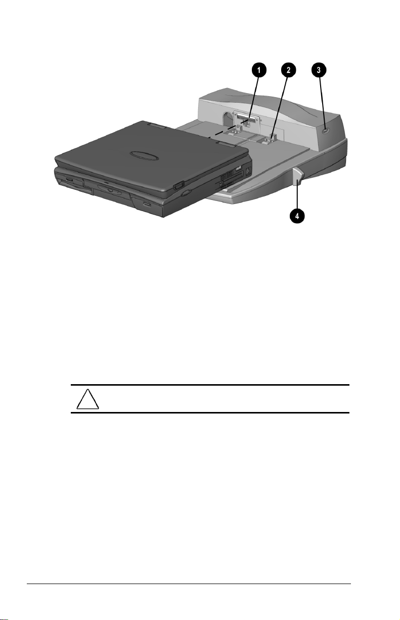
7. Slide the power switch
button on the convenience base.
Docking the computer
3 on the computer, or press the power
Undocking the Computer from the
Convenience Base
The undocking process depends on your operating system. To
undock your computer from the optional convenience base:
1. From the Windows 95 or Windows 98 start menu, click Start
Æ Eject PC. The computer will initiate Suspend and you can
safely undock the computer. If you are using Windows NT,
Shut Down the computer by clicking Start Æ Shut Down.
CAUTION:
loss of data or unpredictable results.
NOTE:
Not all network operating systems support "hot
docking" (while the computer is on).
2. Close the display if not already closed.
NOTE:
Disconnect the PC Card cable and unlock the security
cable, if applicable, to prevent damage.
3. Pull the docking lever fully forward to undock the computer.
8-4 Connecting External Devices
Failure to use the ejection procedure may cause
Page 93

4. Slide the computer forward from the convenience base to
remove.
5. If the computer display is blank, press the computer hotkey
combination
to switch the display from the external
Fn+F4
monitor to the computer display.
Connecting Infrared Equipment
NOTE:
Infrared-equipped computers are IrDA-compliant. Infrared
performance may vary depending on peripherals, distance
between infrared devices, and applications used. The infrared port
is available only on specific models.
For infrared-equipped models, the infrared port allows wireless
communication between your computer and other infraredequipped devices. Operating system support for infrared
communication is currently available with Microsoft Windows 95,
but not for Windows NT.
The infrared port produces an invisible beam of infrared light to
communicate with another infrared-equipped device.
To establish an infrared link:
Be sure the infrared ports on both computers are turned on and
■
facing each other at a distance no greater than 1.5 feet (about
0.5 meter).
Avoid moving the infrared ports away from each other during
■
data transmission.
Avoid interference from remote control units, such as wireless
■
headphones or audio devices, pointed at the infrared ports.
Avoid direct sunlight, fluorescent light, or flashing
■
incandescent light close to the infrared ports.
Keep the path between the infrared ports free of any objects
■
that might interfere with data transmission.
Do not point one of the ports more than 30 degrees (plus or
■
minus 15 degrees off the center line) away from the infrared
port of the device you are connecting with.
Connecting External Devices 8-5
Page 94

Connecting USB Peripherals
Your computer comes equipped with a port that connects
Universal Serial Bus (USB) devices to the computer.
Your computer can support certain USB devices without any
special drivers. These include hubs and keyboards. For most other
USB devices without special drivers provided by the USB device
manufacturer, you will need an operating system which has USB
support for your device built in, such as Windows 95 OSR2.1 or
Windows 98. Later versions of the Windows operating systems
will add functionality which may allow you to attach any USB
device to your computer (for example, a video camera) and will
allow many USB devices to be connected and working
simultaneously.
A USB keyboard and mouse, optionally connected through a hub,
offer the same functionality as a standard keyboard and mouse
connected through the keyboard/mouse connector. Future
operating systems will have extended USB capabilities which will
replace the USB capabilities built into the computer.
8-6 Connecting External Devices
Page 95

chapter
9
SING
U
PC C
ARDS
PC Card Types
This computer can support two Type II cards or one Type III card.
It supports both 16-bit and CardBus (32-bit)
PC Cards. Several kinds of PC Cards are supported, such as
network cards, hard drive cards, memory cards, and fax/modem
cards.
For a current list of third-party PC Cards qualified on this
computer, call your Compaq authorized dealer, reseller, or service
provider.
Inserting a PC Card
1. If you are running Windows NT 4.0 but not CardWare 5.0
from Compaq, turn off the computer. If you are running
Windows 95, you do not need to turn off the computer or
initiate Suspend before inserting a PC Card.
NOTE:
If you are running Windows NT and CardWare 5.0
from Compaq, insertion of the PC Card while the computer is
on is supported for most PC Cards. Contact your PC Card
vendor directly for information about the level of support they
offer for "hot insertion” with CardWare 5.0.
Using PC Cards 9-1
Page 96

2. With the label side up, insert the 68-pin connector side of the
PC Card into the PC Card slot, pushing gently until firmly
seated.
CAUTION:
pressure when inserting a PC Card into a PC Card slot.
To prevent damage to the connectors, use minimal
If you are running Windows 95 and your computer is on, the
computer automatically configures a plug and play card and most
other PC Cards. If the computer is turned off or in Suspend, a card
is not configured until you turn on the computer or exit Suspend.
Windows NT is not plug and play. If you are running Windows
NT, the computer configures a card only when it is in the PC Card
slot when the computer is turned on. The computer only
recognizes that a PC Card has been removed if the PC Card slot is
empty when the computer is turned on.
After the computer has configured the card, the computer beeps
twice to indicate that the card is ready for use.
IMPORTANT:
After the PC Card has been inserted and configured, it
may be necessary to perform an initial setup procedure. For
example, a new storage card may need to be formatted, or a new
network card may need drivers installed. For detailed information
on setup procedures for various Network PC Cards, refer to the
instructions provided by the PC Card manufacturer.
9-2 Using PC Cards
Page 97

Removing a PC Card
1. If you are running Windows 95, you must stop the PC Card
before removing it (see “Stopping a PC Card” later in this
chapter). You do not need to turn the computer off or initiate
Suspend. If you are running Windows NT, you must turn off
the computer.
CAUTION:
damage the PC Card or computer.
Failure to stop a PC Card before it is removed may
2. To release the PC Card eject button, depress the button 1
once. To eject the PC Card, firmly depress PC Card eject
button a second time.
3. Remove the card.
NOTE:
If you are running Windows 95, the computer beeps twice if
it is turned on when the PC Card is removed.
Releasing the PC Card
Using PC Cards 9-3
Page 98

PC Card Device Drivers
Device drivers are programs or data files containing information
needed to run a specific PC Card. Most of the device drivers you
need are preinstalled on the computer.
NOTE:
In order to save available memory, some device drivers are
not enabled after being installed.
Some types of PC Cards, such as network cards, Global
Positioning System (GPS) cards, SCSI cards, audio cards, and
multifunction cards, require an additional PC Card-specific
software device driver to function properly. This software device
driver is provided on diskette by the PC Card manufacturer and
should be installed according to the manufacturer's instructions.
Do not install any other PC Card software on the computer such as
Card and Socket Services, even if prompted to do so.
CAUTION:
the computer. If you install card and socket services or enablers
provided by other vendors over software preinstalled on the
computer, the computer may no longer work properly with all of
your PC Cards.
Compaq has tested the PC Card software preinstalled on
Changing PC Card Settings
To view or configure the adapter in your PC Card, under
Windows 95, access the Device Manager (Start Æ Settings Æ
Control Panel Æ double-click System Æ Device Manager), and
select the appropriate device type for the card you want to
configure.
NOTE:
If your PC Card has never been inserted, a dialog box will
appear when you insert the card into the PC Card slot and will
automatically display setting information for the card.
9-4 Using PC Cards
Page 99

Managing PC Card Power
PC Cards are powered accessories in a small form factor. When
PC Cards are installed in your computer, they draw power from
the system even when they are not in use.
If you are running Windows 95, remove PC Cards when they are
not in use to conserve power, or you may turn off power to the PC
Card slots through Power Properties. (Click Start Æ Settings Æ
Conrol Panel Æ double-click Power Æ Power Properties).
If you are running Windows NT, remove PC Cards when they are
not in use to conserve power.
If you are operating the computer on a battery pack, you can
disable power to the PC Card slots and extend the battery life. You
can also conserve PC Card power when the computer is in
Suspend.
Zoomed Video
A Zoomed Video PC Card promotes higher overall system
performance for MPEG playback.
The computer supports Zoomed Video PC Cards under Windows
95. Windows NT does not support Zoomed Video.
Always insert a Zoomed Video card into the bottom PC Card slot.
Stopping a PC Card
If you are running Windows 95, you should always stop a PC
Card before removing it from a PC Card slot. There are two ways
stop a PC Card:
IMPORTANT:
removing.
Click the PC Card icon in the notification area on the taskbar.
■
A list of PC Cards in the system appears. Click the PC Card
that you want to stop.
Click Start Æ Settings Æ Control Panel Æ PC Card icon.
■
Click the PC Card that you want to stop.
When the message appears that it is safe to remove the card,
remove the PC Card.
Always stop a LAN, ATA, or SCSI card before
Using PC Cards 9-5
Page 100

chapter
10
SING AUDIO FEATURES
U
Audio Components Overview
The computer provides both internal and external audio
capabilities. You can record and play sound, enhance an
interactive demonstration with high-quality stereo sound, and take
advantage of business programs, presentations, and multimedia
educational and entertainment software.
The internal microphone supports audio input for spoken
comments. An external electret condenser microphone can also be
used to record voice or sound.
The integrated stereo speakers support sound output for WAV file
and MIDI playback, and audio from the optional CD-ROM drive.
They also support external audio input devices such as a
CD player, tape deck, or stereo tuner connected to the computer
through the microphone line-in jack. Headphones or external
speakers can be connected to the computer through the stereo
speaker/headphone jack.
Using Audio Features 10-1
 Loading...