

Page 1

Compaq Armada E700
Series of Personal Computers
Reference Guide
Page 2

Notice
The information in this guide is subject to change without notice.
COMPAQ COMPUTER CORPORATION SHALL NOT BE LIABLE FOR
TECHNICAL OR EDITORIAL ERRORS OR OMISSIONS CONTAINED
HEREIN; NOR FOR INCIDENTAL OR CONSEQUENTIAL DAMAGES
RESULTING FROM THE FURNISHING, PERFORMANCE, OR USE OF
THIS MATERIAL.
This guide contains information protected by copyright. No part of this
guide may be photocopied or reproduced in any form without prior
written consent from Compaq Computer Corporation.
© 1999 Compaq Computer Corporation.
All rights reserved. Printed in the U.S., U.K., Singapore, and Taiwan.
OMPAQ
C
Office.
Microsoft, MS-DOS, Windows, Windows NT, and other names of
Microsoft products mentioned herein are trademarks or registered
trademarks of Microsoft Corporation.
Phoenix is a registered trademark of Phoenix Technologies Ltd.
MultiBoot is a trademark of Phoenix Technologies Ltd.
Imation and SuperDisk are trademarks of Imation Corporation.
CardWare is a registered trademark of Award Software International Inc.
All other product names mentioned herein may be trademarks or
registered trademarks of their respective companies.
Software described herein is furnished under a license agreement or
nondisclosure agreement. The software may be used or copied only in
accordance with the terms of the agreement.
and
RMADA
A
are registered in the U.S. Patent and Trademark
EFERENCE GUIDE
R
Compaq Armada E700 Series of Personal Computers
First Edition July 1999
Part Number 103542-001
Compaq Computer Corporation
Page 3

ONTENTS
C
preface
U
SING THIS GUIDE
chapter 1
G
ETTING STARTED
Finding Assistance ...........................................................................1-1
Identifying Packing Box Contents...................................................1-1
chapter 2
T
AKING A LOOK AT THE COMPUTER
Display Component..........................................................................2-1
Top Components..............................................................................2-2
Left Side Components......................................................................2-4
Right Side Components....................................................................2-5
Front Panel Components..................................................................2-6
Rear Panel Components...................................................................2-7
Bottom Components.........................................................................2-8
chapter 3
U
SING THE KEYBOARD
Using the Pointing Device ...............................................................3-1
Identifying Keyboard Components (Pointing-Stick Models).....3-1
Identifying Keyboard Components (Touchpad Models) ............3-2
Navigating with the Pointing Device...........................................3-2
Setting Pointing Device Preferences ...........................................3-3
Using Hotkeys..................................................................................3-4
Switching the Display and Image................................................3-5
Adjusting System Volume...........................................................3-5
Initiating Quick Controls.............................................................3-5
Setting a Power Conservation Level ...........................................3-6
Viewing Battery Charge Status ...................................................3-6
Adjusting Screen Brightness........................................................3-6
Displaying System Information...................................................3-6
Stretching Text.............................................................................3-6
Contents v
Page 4

Using the Embedded Numeric Keypad...........................................3-7
Toggling the Keypad On and Off................................................ 3-7
Operating the Keypad Keys as Standard Keys ........................... 3-7
Enabling the Keypad at Startup................................................... 3-8
chapter 4
I
NSERTING
, R
EMOVING, OR STORING A BATTERY PACK
Selecting a Battery Pack Location...................................................4-1
Inserting Multiple Battery Packs.....................................................4-2
Storing a Battery Pack .....................................................................4-2
Replacing the Primary Battery Pack................................................ 4-3
Inserting or Removing a MultiBay Battery Pack............................ 4-4
Inserting or Removing a Dual-MultiBay Battery Pack................... 4-5
chapter 5
M
ANAGING POWER
Selecting a Power Source ................................................................5-1
Beginning, Leaving, or Resuming Your Work ............................... 5-2
Managing Low-Battery Conditions................................................. 5-4
Identifying Low-Battery Conditions........................................... 5-4
Resolving Low-Battery Conditions............................................. 5-5
Restoring from Hibernation After Resolving a Critical
Low-Battery Condition................................................................5-5
Charging a Battery Pack.................................................................. 5-6
Monitoring the Charge in a Battery Pack........................................ 5-7
Using the Battery Charge Level Lights....................................... 5-7
Using the Battery Status Tab....................................................... 5-7
Using the Battery Meter or Power Meter Icon............................5-8
Using the Power or Power Meter Tab......................................... 5-9
Calibrating a Battery Pack.............................................................5-10
Checking or Running a Calibration...........................................5-11
Stopping a Calibration............................................................... 5-11
Setting Power Preferences............................................................. 5-12
Setting Power Preferences in Windows 95...............................5-13
Setting Power Preferences in Windows 98...............................5-14
Setting Power Preferences in Windows NT 4.0........................ 5-15
Turning Auto Insert Notification On or Off.............................. 5-16
Conserving Battery Power............................................................. 5-17
Battery Power Conservation Checklist .....................................5-17
Conserving Battery Power in Windows 95...............................5-17
Conserving Battery Power in Windows 98...............................5-18
Conserving Battery Power in Windows NT 4.0 ....................... 5-18
vi Contents
Page 5

chapter 6
U
SING DRIVES
Caring for Drives..............................................................................6-1
Removing and Inserting the Primary Hard Drive............................6-1
Removing the Primary Hard Drive..............................................6-2
Inserting the Primary Hard Drive................................................6-3
Using a Drive in a MultiBay............................................................6-4
Selecting a MultiBay Location....................................................6-4
Selecting a MultiBay Drive Adapter ...........................................6-4
Preparing to Insert or Remove a MultiBay Drive .......................6-5
Inserting a Hard Drive into a MultiBay Adapter.........................6-6
Removing a Hard Drive from a MultiBay Adapter.....................6-7
Inserting or Removing a MultiBay Drive....................................6-8
Changing the Startup Sequence with MultiBoot ...........................6-10
chapter 7
S
ECURING THE COMPUTER
Security Features Quick Reference..................................................7-1
If You Forget a Password.................................................................7-1
Setting Passwords and Quick Controls............................................7-2
Using a Power-On Password .......................................................7-3
Using Quick Controls ..................................................................7-4
Using a Setup Password...............................................................7-5
Using DriveLock..........................................................................7-6
Disabling a Device ...........................................................................7-9
Securing the Memory Expansion Compartment............................7-10
Connecting an Optional Cable Lock..............................................7-10
chapter 8
U
SING AUDIO AND VIDEO FEATURES
Using the Internal Microphone and Stereo Speakers.......................8-1
Connecting an External Audio Device ............................................8-2
Selecting an Audio Connector.....................................................8-2
Connecting a Device to the Microphone Jack.............................8-2
Connecting a Device to the Stereo Speaker/Headphone Jack.....8-3
Connecting a Device to the Stereo Line-In Jack.........................8-3
Connecting an External Video Device.............................................8-3
Using the Video-Out Adapter......................................................8-4
Changing the Video Mode...........................................................8-5
Setting Video Preferences............................................................8-5
Contents vii
Page 6

Adjusting Volume............................................................................8-6
Adjusting System Volume...........................................................8-6
Setting Device Volume ............................................................... 8-6
chapter 9
U
SING AN INTERNAL MODEM
Connecting the Modem Cable......................................................... 9-1
Selecting Communication Software................................................ 9-2
Configuring the Modem .................................................................. 9-2
Modem Model............................................................................. 9-2
Other Recommended Settings..................................................... 9-2
Using Modem Commands and Dial Modifiers........................... 9-3
Setting Modem Preferences......................................................... 9-3
Reinstalling Modem Software......................................................... 9-4
Using the Modem............................................................................. 9-5
Using the Modem While Traveling Internationally........................ 9-6
Using a Country-Specific Modem Adapter.................................9-6
Selecting a Country-Specific Modem Configuration ................. 9-7
Travel Connection Checklist....................................................... 9-7
chapter 10
C
ONNECTING TO A LOCAL AREA NETWORK
(LAN)
Connecting the Network Cable...................................................... 10-2
Turning a LAN Connection On and Off........................................ 10-2
Accessing the Network at Startup..................................................10-3
Reinstalling LAN Drivers..............................................................10-3
chapter 11
U
PC C
SING
ARDS
Selecting a PC Card Slot................................................................ 11-1
Configuring a PC Card .................................................................. 11-2
Inserting or Removing a PC Card.................................................. 11-2
Inserting a PC Card ................................................................... 11-3
Removing a PC Card................................................................. 11-4
chapter 12
U
SING INFRARED COMMUNICATION
Communicating with Infrared........................................................12-1
Configuring the Infrared Port ........................................................ 12-2
Enabling the Infrared Port ............................................................. 12-2
viii Contents
Page 7

chapter 13
E
XPANDING MEMORY
Managing Random Access Memory (RAM).................................13-1
Inserting or Removing a Memory Expansion Board.....................13-2
chapter 14
I
NTELLIGENT MANAGEABILITY
Finding Intelligent Manageability Help.........................................14-1
Using Fault Management Alerts ....................................................14-2
Identifying a Fault Management Alert ......................................14-2
Setting Fault Management Alert Preferences............................14-2
chapter 15
C
ONFIGURATION AND DIAGNOSTIC UTILITIES
Selecting Computer Setup or Compaq Diagnostics.......................15-1
Using Computer Setup...................................................................15-2
Selecting from the File Menu....................................................15-2
Selecting from the Security Menu.............................................15-3
Selecting from the Advanced Menu..........................................15-4
Using Compaq Diagnostics............................................................15-5
Displaying System Information.................................................15-5
Running a Diagnostic Test.........................................................15-5
chapter 16
M
AINTENANCE
, S
HIPPING, AND TRAVEL
Updating the System ......................................................................16-1
Obtaining Customized Update Information with Info Messenger16-1
Obtaining Software Updates and Enhancements by Subscription16-1
Obtaining Software Updates from the Compaq Internet Site ...16-2
Updating the System ROM........................................................16-2
Reinstalling Software.....................................................................16-3
Caring for the Computer ................................................................16-4
Preparing the Computer for Shipping or Travel............................16-4
Traveling with the Computer.........................................................16-5
chapter 17
T
ROUBLESHOOTING
Quick Solutions Checklist..............................................................17-2
Solving Audio Problems................................................................17-3
Solving Battery Problems ..............................................................17-4
Contents ix
Page 8

Solving Drive Problems................................................................. 17-7
Solving Hard Drive Problems................................................... 17-7
Solving CD-ROM and DVD-ROM Drive Problems................17-8
Solving Diskette and SuperDisk LS-120 Drive Problems........17-9
Solving Infrared Problems...........................................................17-11
Solving Keyboard and Pointing Device Problems...................... 17-13
Solving LAN Connection Problems............................................ 17-14
Solving Memory Problems.......................................................... 17-14
Solving Modem Problems ...........................................................17-15
Solving PC Card Problems..........................................................17-20
Solving Power Problems..............................................................17-21
Solving Screen Problems............................................................. 17-23
Solving USB Problems................................................................ 17-24
appendix A
C
OMPAQ CUSTOMER SUPPORT
Using the Worldwide Web ............................................................. A-1
Preparing to Call Technical Support .............................................. A-1
Worldwide Telephone Numbers..................................................... A-2
appendix B
R
EGULATORY NOTICES
..............................................................................B-1
appendix C
E
LECTROSTATIC DISCHARGE
Preventing Electrostatic Discharge..................................................C-1
When Handling Drives................................................................C-1
When Installing Internal Components ........................................C-1
Grounding Methods.........................................................................C-2
appendix D
S
PECIFICATIONS
Computer Dimensions .................................................................... D-1
Operating Environment .................................................................. D-1
Rated Input Power .......................................................................... D-2
Port and COM Port Settings........................................................... D-2
Modem Specifications .................................................................... D-2
I
......................................................................................................I-1
NDEX
x Contents
Page 9

preface
USING THIS GUIDE
Some or all of the following format conventions are used in this
guide to distinguish elements of text:
■ Names of keys are shown in bold type as they appear on the
keyboard, for example,
■ Keys that you should press at the same time are represented by
the key names and the plus (+) symbol, for example,
Ctrl+Alt+Delete.
■ Commands are presented in lowercase, bold type as shown
install or a:\install.
here:
■ An arrow symbol is used to separate icons or menu options
that you should select in succession; for example, select
StartÅSettingsÅControl Panel.
Ctrl, Backspace, Tab.
■ When you need to type information without pressing the Enter
key, you are directed to “type” the information.
■ When you need to type information and press the Enter key,
you are directed to “enter” the information.
NOTE: Text set off in this manner presents commentary, sidelights,
or interesting points of information.
IMPORTANT: Text set off in this manner presents clarifying
information or specific instructions.
WARNING: Text set off in this manner indicates that failure to
!
follow directions could result in bodily harm or loss of life.
CAUTION: Text set off in this manner indicates that failure to
follow directions could result in damage to equipment or loss
of work.
Using This Guide xi
Page 10

chapter
1
GETTING STARTED
Finding Assistance
■ For setup instructions, refer to the setup poster included with
the computer.
■ To access the online quick reference guide for the computer
■ Select the Armada Quick Reference icon on the desktop
or
■ Select StartÅCompaq Information CenterÅArmada
Quick Reference.
■ To access additional information about the computer
■ Select StartÅCompaq Information Center.
■ Go to the Compaq Internet site at
http://www.compaq.com.
■ To contact Compaq customer support, refer to Appendix A in
this guide.
Identifying Packing Box Contents
The contents of the packing box vary by geographic region and the
computer hardware configuration ordered.
The following illustration and component list identify the standard
components included with most computer models.
As you unpack the box, make sure you have received all the
standard and optional components you ordered.
Getting Started 1-1
Page 11
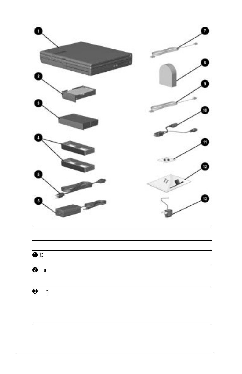
Identifying Hardware Components
Component Function
1
Computer Compaq Armada E700 Personal
2
Hard drive (inserted in
computer hard drive bay)
3
Battery pack (inserted in
computer battery bay)
1-2 Getting Started
Computer.
Primary hard drive when used in hard
drive bay. Can also be used, with an
adapter, in the Dual MultiBay.
Primary battery pack.
NOTE: The battery pack can be charged
and used as shipped, but battery
charge displays will not be accurate
until the battery pack is calibrated.
Continued
Page 12

Identifying Hardware Components
Continued
Component Function
4
Weight savers (2) ■ Protect an empty MultiBay.
■ Can replace a MultiBay device to
reduce computer weight.
NOTE: A weight saver can be inserted or
removed while the computer is on, off,
in Hibernation, or in Suspend.*
5
Power cord ■ Internal adapter models: connects
6
AC Adapter (external AC
Adapter models only)
7
Modem cable (internal
modem models only)
8
Country-specific modem
adapter (provided with
internal modem models by
region as required)
9
Network cable (network
models only)
:
Video-out adapter Adapts video-out jack to S-video and
;
Bag containing two spare
pointing stick caps
(EasyPoint IV pointing-stick
models only)
<
Security kit containing
■ Torx T-10 memory
security screws (2)
■ Torx T-10 screwdriver
to use with memory
security screws
=
3-to-2-prong plug adapter
(Japan only)
*In Windows 98 the term
Standby
computer to AC electrical outlet.
■ External adapter models: connects
AC Adapter to AC electrical outlet.
Converts AC power to DC power.
Connects modem to RJ-11 telephone
jack or to a country-specific adapter.
Adapts modem cable to non-RJ-11
telephone jacks.
Connects computer to an Ethernet
network jack.
composite video devices.
To replace a worn pointing stick cap:
1. Turn off the computer.
2. Gently pull off the used rubber
pointing stick cap, then push the
replacement cap into place.
The screws are tamper-resistant
replacement screws for the memory
expansion compartment cover.
■ If the computer shipped with an
empty memory expansion
compartment, the cover is secured
with a standard screw.
■ If the computer shipped with a
factory-installed memory expansion
board, the cover is secured with a
Torx T-10 memory security screw.
Adapts the power cord to a 2-prong
electrical outlet.
replaces the term
Suspend.
Getting Started 1-3
Page 13

WARNING: To reduce the risk of personal injury, electric shock,
!
fire, or damage to the equipment:
■ Do not disable the power cord grounding plug. The grounding
plug is an important safety feature.
■ Plug the equipment into a grounded (earthed) electrical outlet that
is easily accessible at all times.
■ Disconnect power from the equipment by unplugging the power
cord from the electrical outlet.
■ Do not place anything on power cords or cables. Arrange them so
that no one may accidentally step on or trip over them. Do not
pull on a cord or cable. When unplugging from the electrical
outlet, grasp the cord by the plug.
1-4 Getting Started
Page 14
chapter
2
TAKING A LOOK AT THE
COMPUTER
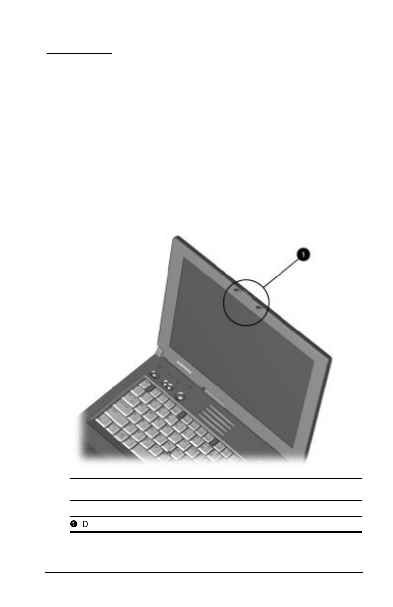
Display Component
Display Component
Component Function
1
Display release latch Opens the computer.
Taking a Look at the Computer 2-1
Page 15
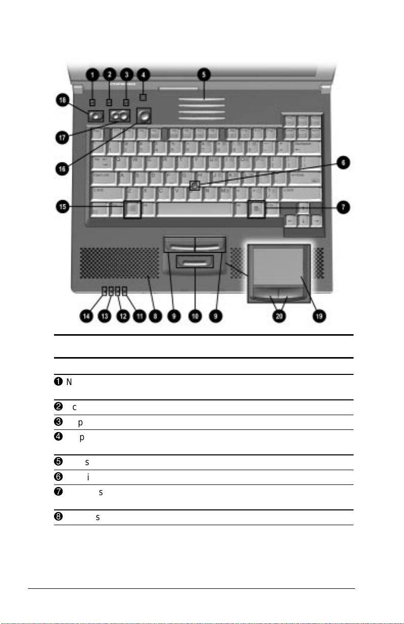
Top Components
Component Function
1
Num lock light On: Num lock is on and the embedded numeric
2
Scroll lock light On: Scroll lock is on.
3
Caps lock light On: Caps lock is on.
4
Display switch Turns off the computer display if the computer
5
Vents Allow airflow to cool internal components.
6
Pointing stick Moves the pointer.
7
Windows
application key
8
Stereo speakers (2) Produce stereo sound.
2-2 Taking a Look at the Computer
Top Components
keypad is enabled.
is closed while on.
Displays shortcut menu for item beneath
pointer.
Continued
Page 16

Top Components
Continued
Component Function
9
Left and right
pointing-stick
buttons (pointingstick models only)
:
Scroll pointing-stick
button (pointingstick models only)
;
MultiBay light On: A drive in a MultiBay is being accessed.
<
Hard drive light On: The primary hard drive is being accessed.
=
Power/suspend
light
>
Battery light On: A battery pack is charging.
?
Microsoft logo key Displays Windows Start menu.
@
Suspend button** ■ Turns on the computer if it is off.
A
Volume buttons (2) Adjust or mute system volume.
B
Power switch Turns the computer on or off or exits Suspend.*
C
Touchpad
(touchpad models
only)
D
Left and right
touchpad buttons
(touchpad models
only)
*In Windows 98 the term
**In Windows 98 the term
button.
Function like the left and right buttons on an
external mouse.
Can be set to scroll, magnify, or function like
the scroll button on an external mouse.
On: Power is turned on.
Off: Power is turned off.
Blinking: Computer is in Suspend.*
NOTE: The power/suspend light also blinks if a
battery pack that is the only available power
source reaches a critical low-battery condition
while Hibernation is disabled.
Blinking: A battery pack that is the only
available power source has reached a
low-battery condition.
■ Initiates and exits Suspend.*
■ When pressed with the Fn key, initiates
Hibernation.
Moves the pointer, selects, and activates.
Function like the left and right buttons on an
external mouse.
Used with the touchpad, the left touchpad
button drags and highlights.
Standby
sleep button
replaces the term
replaces the term
Suspend.
suspend
Taking a Look at the Computer 2-3
Page 17
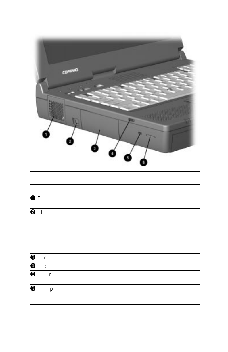
Left Side Components
Left Side Components
Component Function
1
Fan Provides airflow to cool internal
2
Video-out jack Connects a television, VCR,
3
Hard drive bay Holds primary hard drive.
4
Left acoustic port Enhances bass sound.
5
Security cable slot Attaches an optional security cable to
6
Microphone Inputs single-channel sound to the
2-4 Taking a Look at the Computer
components.
camcorder, overhead projector, or
video capture card.
NOTE: The connection requires the
use of the video-out adapter included
with the computer and an optional
video cable.
the computer.
computer; can be used whether the
computer is open or closed.
Page 18
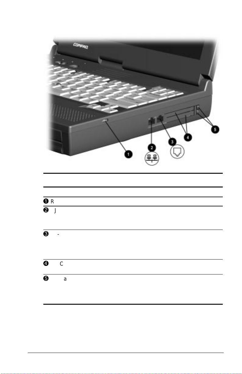
Right Side Components
Right Side Components
Component Function
1
Right acoustic port Enhances bass sound.
2
RJ-45 jack (network models
only)
3
RJ-11 jack (internal modem
models only)
4
PC Card slots (2) Support 32-bit (CardBus) and 16-bit
5
PC Card eject buttons (2) Top button: Ejects a PC Card from the
Connects the network cable.
NOTE: A network cable is included with
network models.
Connects the modem cable to an
internal modem.
NOTE: A modem cable is included with
internal modem models.
PC Cards.
top PC Card slot.
Bottom button: Ejects a PC Card from
the bottom PC Card slot.
Taking a Look at the Computer 2-5
Page 19

Front Panel Components
Front Components
Component Function
1
Microphone jack Connects a single sound
2
Stereo line-in jack Connects a CD player, tuner, or
3
Stereo speaker/headphone
jack
4
Battery bay Holds the primary battery pack.
5
Top MultiBay* Supports a12.7-mm Armada drive
6
Bottom MultiBay* Supports a 12.7-mm Armada drive or
*The Dual MultiBay, which comprises both the top and bottom
MultiBays, supports devices, such as a 17-mm Armada hard drive or a
Dual-MultiBay battery pack, which fill both the top and bottom MultiBays.
channel microphone.
tape deck.
Connects stereo speakers,
headphones, headset, or television
audio.
other than a diskette drive.
a MultiBay battery pack.
2-6 Taking a Look at the Computer
Page 20
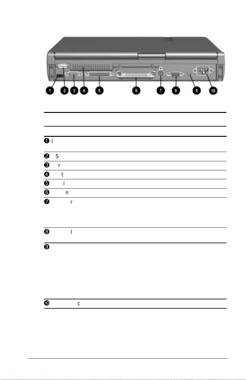
Rear Panel Components
Rear Panel Components
Component Function
1
Infrared port Links another IrDA-compliant device for
2
USB connector Connects USB devices.
3
Serial connector Connects a serial device.
4
Vents Allow airflow to cool internal components.
5
Parallel connector Connects a parallel device.
6
Docking connector Connects the computer to a docking base.
7
Keyboard/mouse
connector
8
External monitor
connector
9
DC power jack Connects any one of the following:
:
AC power connector Connects the power cord.
wireless communication.
Connects an external keyboard or PS/2compatible external mouse.
NOTE: To connect a keyboard and a mouse at
the same time, use an optional Y-adapter.
Connects an external monitor or overhead
projector.
■ AC Adapter (external adapter models
■ Optional Automobile Power Adapter/
■ Optional Aircraft Power Adapter.
■ Optional DC cable.
only).
Charger.
Taking a Look at the Computer 2-7
Page 21
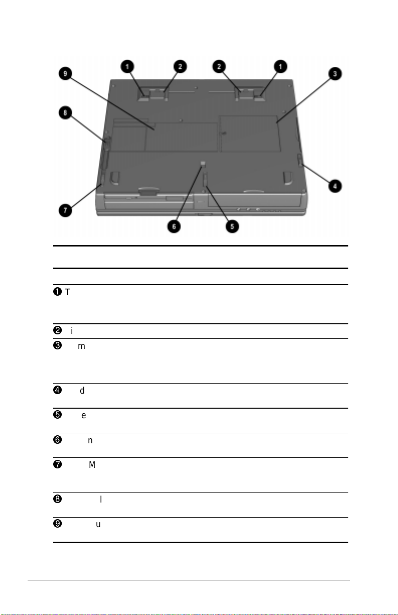
Bottom Components
Bottom Components
Component Function
1
Tilt feet latches (2) Release tilt feet.
2
Tilt feet (2) Tilt the computer.
3
Memory expansion
compartment cover
4
Hard drive release latch Releases a hard drive from the hard
5
Battery release latch Releases the primary battery pack
6
Docking restraint latch
recess
7
Front MultiBay release latch Releases a device from the bottom
8
Rear MultiBay release latch Releases a device from the top
9
Serial number Identifies computer; needed when you
Note: To close tilt feet, press the feet
against the bottom of the computer.
Covers the memory expansion
compartment, which contains two
memory expansion slots for memory
expansion boards.
drive bay.
from the battery bay.
Helps secure the computer to a
docking base.
MultiBay or a device which fills both
the top and bottom MultiBays.
MultiBay.
call Compaq customer support.
2-8 Taking a Look at the Computer
Page 22
chapter
3
USING THE KEYBOARD
Using the Pointing Device
The pointing stick (pointing-stick models) and the touchpad
(touchpad models) function with any software that supports a
Microsoft-compatible mouse.
NOTE: For software that does not support a Microsoft-compatible
mouse, open Computer Setup, select AdvancedÅDevice Options,
then select the Disable Multiple Pointing Devices checkbox.
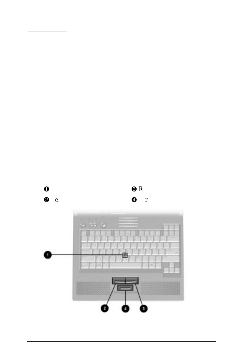
Identifying Keyboard Components (Pointing-Stick Models)
Pointing stick
1
Left pointing-stick button
2
Right pointing-stick button
3
Scroll pointing-stick button
4
Using the Keyboard 3-1
Page 23
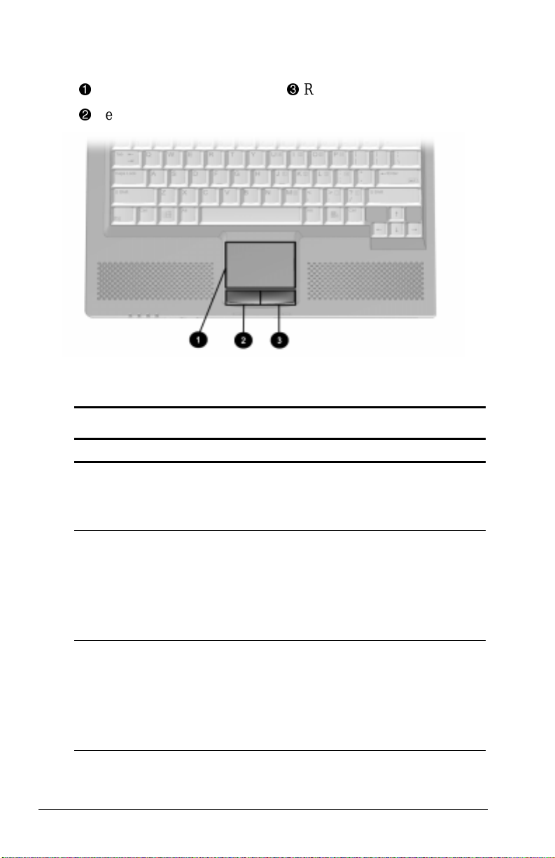
Identifying Keyboard Components (Touchpad Models)
Touchpad
1
Left touchpad button
2
Right touchpad button
3
Navigating with the Pointing Device
Pointing Device Procedures
Task Procedure
Move the pointer. Pointing stick: Directionally press the
Increase or decrease
pointer speed as you move
the pointer.
To set a pointer speed
preference, refer to
“Setting Pointing Stick
Preferences.”
Right-, left-, or scroll-click,
or double-click.
pointing stick.
Touchpad: Move your finger directionally
across the touchpad surface.
Pointing stick: Increase or decrease the
pressure on the pointing stick.
Touchpad: Increase or decrease finger
speed across the touchpad surface.
Pointing stick: Press the right, left, or scroll
pointing-stick button as you would the
right, left, or scroll button on an external
mouse.
Touchpad: Press the right or left touchpad
button as you would the right or left button
on an external mouse.
Continued
3-2 Using the Keyboard
Page 24

Pointing Device Procedures
Continued
Task Procedure
Highlight an item.* Position the pointer at the item to be
Select text or an object.* Position the pointer over the highlighted
Activate a selection.* Position the pointer over the selection,
Select, then drag and drop
an item.*
*To perform this task exactly as you would with an external mouse, use
the left pointing device button like an external mouse left button.
highlighted. Quickly tap the pointing stick
or touchpad once, then hold down on the
pointing stick or touchpad as you move the
pointer over the item.
text or object, then quickly tap the pointing
stick or touchpad once.
then quickly tap the pointing stick or
touchpad twice.
NOTE: To select and activate a preference,
first tap the preference once to select it,
then tap the preference twice to activate it.
Position the pointer over the highlighted
text or object. Quickly tap the pointing stick
or touchpad once, then hold down on the
pointing stick or touchpad while dragging
the item to the new location. To drop the
item, release the pressure.
Setting Pointing Device Preferences
■ Pointing-stick models—
■ To access settings common to any Microsoft-compatible
mouse, such as mouse trails, pointer speed, double-click
pace, and Windows 98 single-click mode, select StartÅ
SettingsÅControl PanelÅMouse.
■ To access settings and instructions for using additional
pointing-stick features, such as scrolling, magnifying, and
selecting, select StartÅSettingsÅControl PanelÅ
EasyPoint IV.
■ Touchpad models—To access all touchpad features and
settings, including mouse trails, pointer speed, double-click
pace, and Windows 98 single-click mode, select StartÅ
SettingsÅ Control PanelÅMouse.
Using the Keyboard 3-3
Page 25
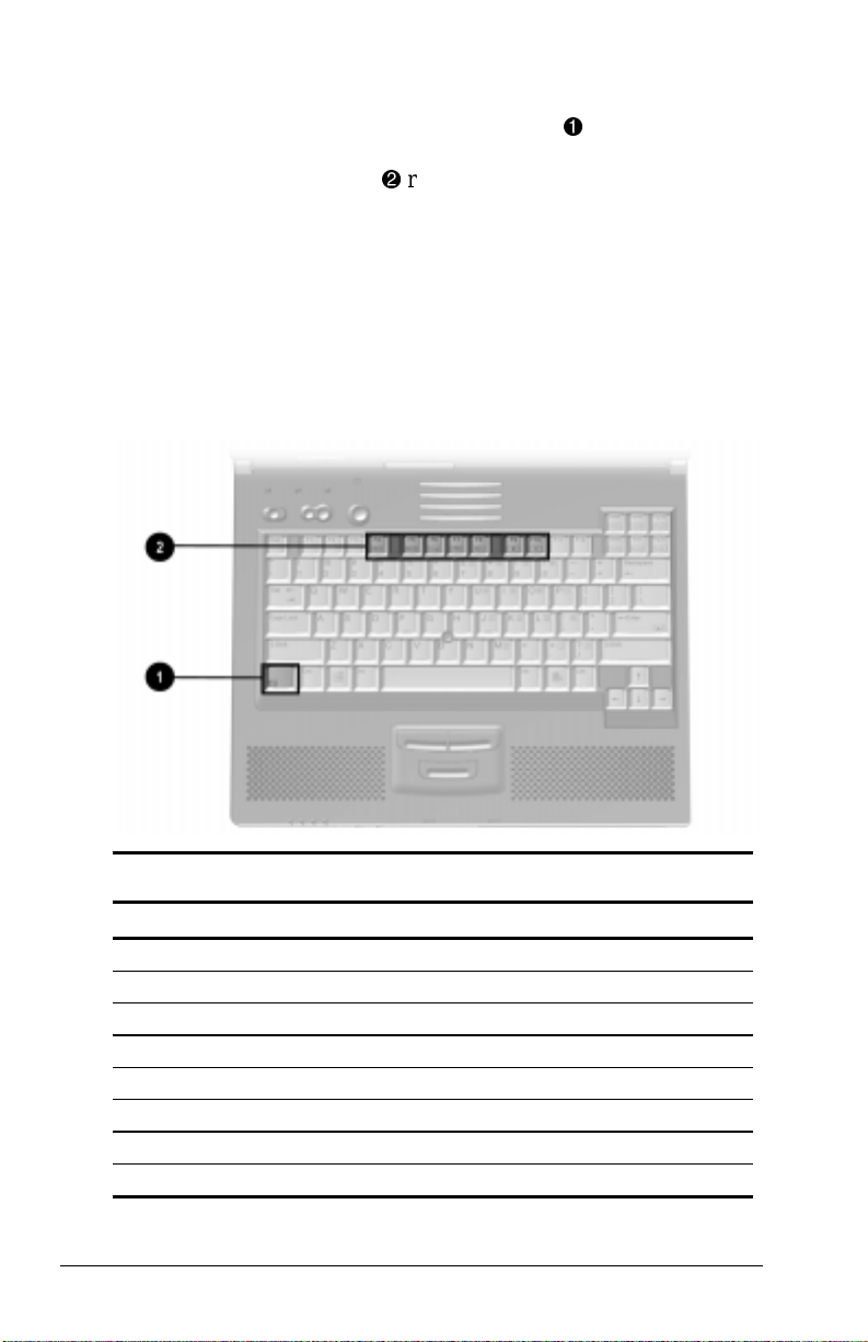
Using Hotkeys
Hotkeys are preset combinations of the Fn key 1 plus a second key
that access or execute frequently used system functions. The icons
on the function keys
■ To use hotkeys on an external keyboard, which does not
have an
Fn key, press the Scroll Lock key twice, then the second
F1-F10
key only of the hotkeys combination. For example, to use the
Fn+F10 hotkeys, press Scroll Lock+Scroll Lock+F10.
NOTE: The Fn+F6 hotkeys cannot be used on an external
keyboard connected through a USB connector.
■ To close a window opened with hotkeys, use standard
Windows procedures or press the hotkeys again.
represent these functions.
2
Hotkeys Quick Reference
Task Hotkeys
Switch the display and image. Fn+F4
Adjust system volume. Fn+F5
Initiate Quick Controls. Fn+F6
Set a power conservation level. Fn+F7
View battery charge status. Fn+F8
Adjust screen brightness. Fn+F10
Display system information. Fn+Esc
Stretch text. Fn+T
3-4 Using the Keyboard
Page 26

Switching the Display and Image
In Windows 95 or Windows NT 4.0 toggle Fn+F4 to switch the
image among the computer display, an external display, and
simultaneous display. The external display can be connected
through the external monitor connector or the video-out jack.
In Windows 98 toggle
Fn+F4 to switch the image between the
computer display and an external display that is connected through
the external monitor connector.
■ When MultiMonitor is enabled, press Fn+F4 to turn off the
external display and disable MultiMonitor.
■ When MultiMonitor is disabled, toggle Fn+F4 to switch the
image among the computer display, the external display, and
simultaneous display.
Adjusting System Volume
■ To adjust system volume with an onscreen slide button or with
the keyboard arrow keys, press
■ To mute or restore volume
■ Press Fn+F5+M
or
■ Press Fn+F5, then select or clear the Mute checkbox.
Fn+F5.
Initiating Quick Controls
Quick Controls security features disable the keyboard and pointing
device and clear the screen. Before you can use Quick Controls,
you must set a power-on password and enable Quick Control
preferences. For instructions, refer to Chapter 7.
■ To initiate Quick Controls manually, press Fn+F6.
■ To exit Quick Controls, enter your power-on password.
The
Fn+F6 hotkeys cannot be used on an external keyboard
connected through a USB connector on the computer or an
optional docking base.
Using the Keyboard 3-5
Page 27

Setting a Power Conservation Level
In Windows 98 press Fn+F7 to open the Power Schemes window.
In Windows 95 or Windows NT 4.0 press
Fn+F7 to open the
Battery Conservation Settings window.
■ To select a preset battery conservation level, choose among
■ High—Maximizes running time from a single charge.
■ Medium—Balances system performance with running time.
■ None (Drain)—Runs the computer at full power.
■ For information about the Custom level, refer to “Using Power
Preferences” in Chapter 5.
Viewing Battery Charge Status
Press Fn+F8 to view the status of all installed battery packs. Battery
packs are listed by location.
■ To display the location of a listed battery pack, select the
corresponding battery icon.
■ A lightening bolt icon beside a battery icon indicates that the
battery pack in that location is charging.
NOTE: The availability of docking base bays varies by model and
configuration.
Adjusting Screen Brightness
Press Fn+F10 to adjust the brightness of the computer screen
with an onscreen slide button or with the arrow keys.
Displaying System Information
Press Fn+Esc to display information about system hardware
components and software version numbers.
NOTE: The number beside System BIOS is the version number of
your system ROM.
Stretching Text
When the computer is running MS-DOS under Windows and the
desktop area resolution is set lower than the display resolution,
Fn+T to toggle the image between Text Stretch, which
press
stretches the text to fill more of the screen, and Regular. Text
Stretch is the default. While Regular is selected, a graphics
accelerator cannot be enabled.
3-6 Using the Keyboard
Page 28
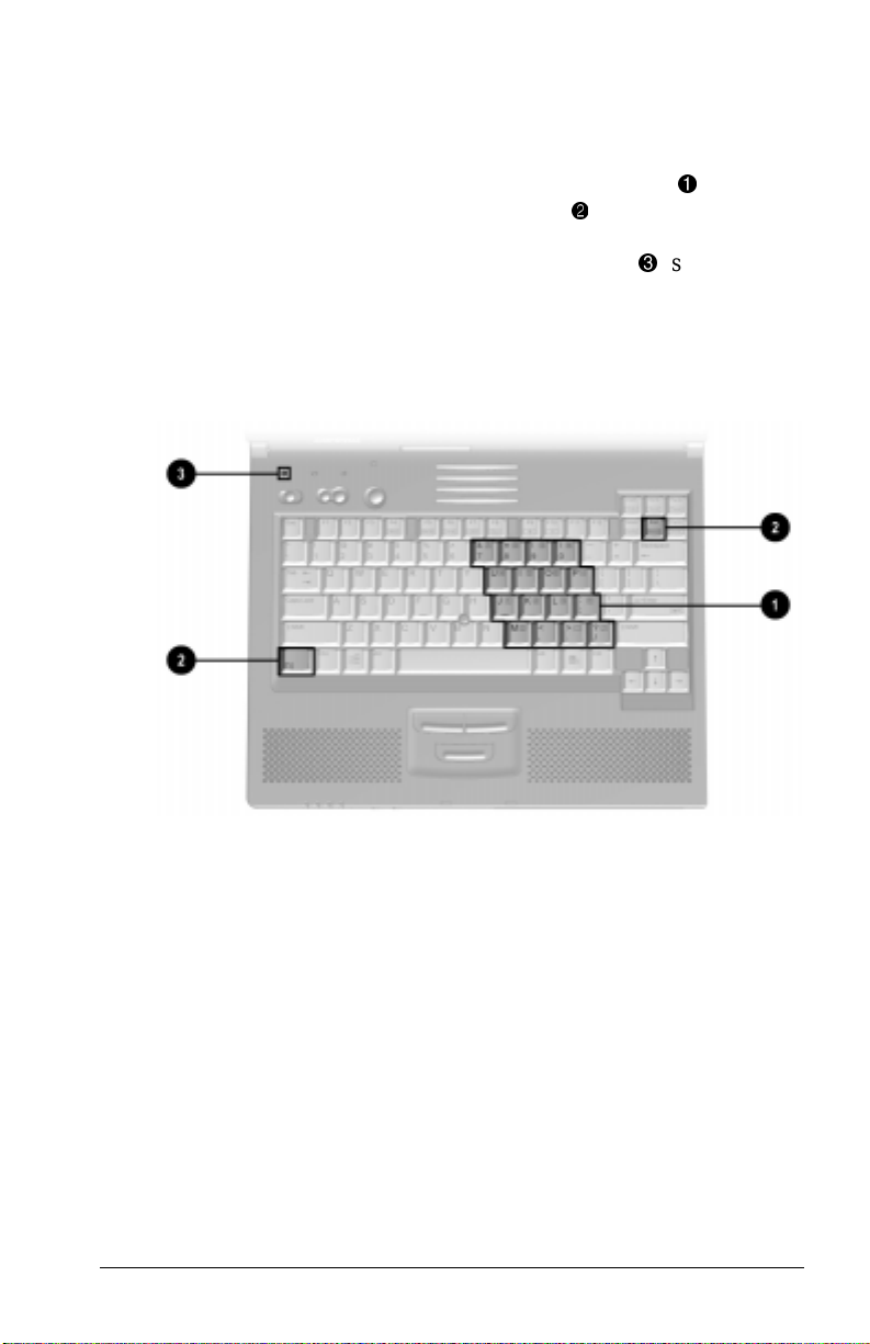
Using the Embedded Numeric Keypad
Toggling the Keypad On and Off
■ To convert the embedded numeric keypad section
keyboard to a keypad, press
Fn+Num Lk 2. When the embedded
of the
1
numeric keypad is enabled, the characters upper-right on the
keypad keys are active and the num lock light 3 is on.
■ To disable the embedded numeric keypad, press Fn+Num Lk.
■ The embedded numeric keypad cannot be enabled while
an optional external keyboard or numeric keypad is connected
to the computer.
Operating the Keypad Keys as Standard Keys
To use the embedded numeric keypad keys as standard keyboard
keys while the keypad is enabled:
■ Press and hold Fn to type in lowercase.
■ Press and hold Fn+Shift to type in uppercase.
Using the Keyboard 3-7
Page 29

Enabling the Keypad at Startup
■ To set the computer to start up with the embedded
numeric keypad enabled—
1. Turn on or restart the computer, then press
F10 when the
blinking cursor appears upper-right on the screen.
■ To change the language, press F2.
■ For navigation instructions, press F1.
2. Select AdvancedÅDevice Options, then press Enter.
3. Toggle on the Num Lock State at Boot field, then press F10.
4. To save your preferences, then close Computer Setup and
restart the computer, select FileÅSave Changes and Exit,
then press
Enter.
5. When prompted to confirm your action, press F10.
■ To disable the embedded numeric keypad at startup—
Repeat the above procedure, toggling off the Num Lock State
at Boot field.
NOTE: The embedded numeric keypad can be enabled or disabled
Fn+Num Lk in either startup state.
with
3-8 Using the Keyboard
Page 30

chapter
4
INSERTING, REMOVING, OR
STORING A BATTERY PACK
Selecting a Battery Pack Location
WARNING: To reduce the risk of personal injury or damage to the
!
battery pack, do not crush, puncture, or incinerate the battery pack
or short the metal contacts. Do not attempt to open or service the
battery pack.
The following battery packs can be used in the computer only in
the indicated locations.
Selecting a Battery Pack Location
Battery Pack Location
Primary battery pack (8 cell, 17 mm,
included with the computer)
MultiBay battery pack (6 prismatic cell,
12.7 mm, optional)
Dual-MultiBay battery pack (12 cell,
25 mm, optional)
Inserting, Removing, or Storing a Battery Pack 4-1
Battery bay
Bottom MultiBay
MultiBay (fills both top and
bottom MultiBays)
Page 31

Inserting Multiple Battery Packs
The computer supports up to two battery packs, one in the
battery bay and one in a MultiBay. A drive can be inserted in
the top MultiBay while a MultiBay battery pack is in the
bottom MultiBay.
Multiple battery packs in the system charge and discharge by
location in a preset sequence.
■ Charge sequence—(1) computer battery bay, (2) computer
MultiBay, (3) expansion base right MultiBay or convenience
base battery charging bay, (4) expansion base left MultiBay or
convenience base MultiBay.
NOTE: The availability of docking base bays varies by model
and configuration.
■ Discharge sequence—(1) computer MultiBay, (2) computer
battery bay.
While a battery pack is in a docking base bay, the battery pack can
be charged, but cannot be used to run the computer.
Storing a Battery Pack
CAUTION: To prevent damage to a battery pack, do not expose it to
high temperatures for extended periods of time.
If the computer will be unused and unplugged from an external
power source for more than 2 weeks, remove and store the
battery pack(s).
Proper storage procedures reduce the self-discharge rate of a
battery pack. Store a battery pack in a cool, dry place within the
following temperature ranges.
Recommended Battery Pack Storage Temperatures
Storage Time Temperature Range °F Temperature Range °C
Less than
1 month
No more than
3 months
Unlimited 32°– 86° 0°–30°
4-2 Inserting, Removing, or Storing a Battery Pack
32°–122° 0°–50°
32°–104° 0°–40°
Page 32

Replacing the Primary Battery Pack
CAUTION: To prevent loss of work while replacing a battery pack
that is the only power source available to the system:
■ Initiate Suspend (Standby) before removing the discharged
battery pack.
■ Insert the replacement battery pack within 5 minutes after
removing the discharged battery pack.
1. If the computer is on, a MultiBay does not contain a
charged battery pack, and the system is not connected to
external power, initiate Suspend (Standby) by pressing the
suspend button.
NOTE: Extensive drive activity may delay Suspend (Standby).
2. Insert or remove the battery pack.
■ To remove the primary battery pack—Tilt the computer
up 1, then slide the battery release latch 2 toward the rear
of the computer while pulling on the center lower edge of
the battery pack 3.
■ To insert the primary battery pack—With the large label
facing up and the contacts facing the computer, slide the
battery pack into the battery bay.
3. If you initiated Suspend (Standby), press the suspend button to
return your work to the screen.
Inserting, Removing, or Storing a Battery Pack 4-3
Page 33

Inserting or Removing a MultiBay Battery
Pack
CAUTION: To prevent loss of work while replacing a battery pack
that is the only power source available to the system:
■ Initiate Suspend (Standby) before removing the discharged
battery pack.
■ Insert the replacement battery pack within 5 minutes after
removing the discharged battery pack.
1. If the computer is on, the battery bay does not contain a
charged battery pack, and the system is not connected to
external power, initiate Suspend (Standby) by pressing the
suspend button.
NOTE: Extensive drive activity may delay Suspend (Standby).
2. Insert or remove the battery pack.
■ To remove a MultiBay battery pack— Tilt the computer
up 1, then slide the front MultiBay release latch 2 toward
the rear of the computer while pulling on the center lower
edge of the battery pack 3.
■ To insert a MultiBay battery pack—With the large label
facing up and the contacts facing the computer, slide the
battery pack into the bottom MultiBay.
3. If you initiated Suspend (Standby), press the suspend button to
return your work to the screen.
4-4 Inserting, Removing, or Storing a Battery Pack
Page 34

Inserting or Removing
a Dual-MultiBay Battery Pack
Inserting a Dual-MultiBay Battery Pack into
the Dual MultiBay
CAUTION: To prevent loss of work while replacing a battery pack
that is the only power source available to the system:
■ Initiate Suspend (Standby) before removing the discharged
battery pack.
■ Insert the replacement battery pack within 5 minutes after
removing the discharged battery pack.
1. Rotate the flap onto the top of the battery pack and snap the
flap into place 1.
2. With the large label facing up and the contacts facing the
computer, insert the battery pack as if you were inserting it
into the bottom MultiBay, then slide the battery pack into the
Dual MultiBay 2.
3. If you initiated Suspend (Standby) before replacing a
battery pack, press the suspend button to return your work to
the screen.
Inserting, Removing, or Storing a Battery Pack 4-5
Page 35

Removing a Dual-MultiBay Battery Pack from
the Dual MultiBay
CAUTION: To prevent loss of work while replacing a battery pack
that is the only power source available to the system:
■ Initiate Suspend (Standby) before removing the discharged
battery pack.
■ Insert the replacement battery pack within 5 minutes after
removing the discharged battery pack.
1. If the computer is on, the battery bay does not contain a
charged battery pack, and the system is not connected to
external power, initiate Suspend (Standby) by pressing the
suspend button.
NOTE: Extensive drive activity may delay Suspend (Standby).
2. Tilt the computer up 1, then slide the front MultiBay release
latch 2 toward the rear of the computer while pulling on the
center lower edge of the battery pack 3.
4-6 Inserting, Removing, or Storing a Battery Pack
Page 36

chapter
5
MANAGING POWER
Selecting a Power Source
Selecting a Power Source
Task Power Source
Work within installed
applications.
Charge or calibrate a
battery pack in the
computer.
Install, reinstall, update,
or perform other major
modifications to system
software.
■ Charged battery pack in the computer
or
■ External power supplied through one of
the following:
■ Power cord or optional DC cable
■ Optional docking base
■ Optional Automobile Power
Adapter/Charger
■ Optional Aircraft Power Adapter
External power supplied through
■ Power cord
■ Optional docking base
■ Optional Automobile Power
Adapter/Charger
External power supplied through
power cord or optional DC cable
Managing Power 5-1
Page 37

Beginning, Leaving, or Resuming Your Work
You can conserve power and reduce startup time by using
Suspend (Standby) or Hibernation.
■ Suspend, called Standby in Windows 98, is an energy-saving
feature that reduces power to system components that are not
being used. When the computer is in Suspend (Standby), your
work is saved in random access memory (RAM) and the
screen is cleared.
■ Hibernation is an energy-saving feature that saves all
information in RAM to a hibernation file on the hard drive,
then shuts down the computer.
If you plan to resume shortly—Initiating Suspend (Standby)
clears the screen, uses less power than leaving the computer on,
and your work returns instantly to the screen when you exit
Suspend (Standby). A fully charged battery pack can support
Suspend (Standby) for up to 2 weeks, but frequent charging and
discharging shorten battery pack life.
If you plan to resume within two weeks—Initiating Hibernation
clears the screen, saves your work to the hard drive, and uses less
power than Suspend (Standby). Returning to work saved in
Hibernation takes longer than returning to work placed in Suspend
(Standby), but is faster than returning to your place manually after
restarting the computer. A fully charged battery pack supports
Hibernation indefinitely.
If the computer will be disconnected from external power for
more than two weeks—Shutting down the computer and
removing the battery pack extends the useful life of the battery
pack. Store the battery pack in a cool, dry place.
Beginning, Leaving, or Resuming Your Work
Task Procedure Result
Turn the
computer
on from
shutdown.
Shut down
the
computer.
5-2 Managing Power
■ Slide power switch.
or
■ Press suspend
button.**
Shut down the
computer as directed by
your operating system
documentation.
Power/suspend* light turns on.
Operating system loads.
Power/suspend* light turns off.
Operating system closes and
turns off all power.
Computer turns off.
Continued
Page 38

Beginning, Leaving, or Resuming Your Work
Task Procedure Result
Initiate
Suspend.*
Exit
Suspend.*
Initiate
Hibernation.
Restore
from
Hibernation.
*In Windows 98 the term
**In Windows 98 the term
suspend button.
■ Press suspend
button.**
or
■ In Windows 95,
select Suspend on
the Start menu
■ In Windows 98,
select Stand by on
the Shutdown
menu.
■ Press suspend
button.**
or
■ Slide power switch.
Press Fn + suspend
button.
Slide power switch. Power/suspend* light turns on.
Standby
sleep button
Power/suspend* light blinks.
System beeps twice.
Screen clears.
Power/suspend* light turns on.
System beeps once.
Your work returns to the screen.
Power/suspend* light turns off.
System beeps twice.
Screen clears.
System beeps once.
Your work returns to the screen.
replaces the term
replaces the term
Continued
Suspend.
1
Power switch
2
Suspend button
3
Fn key
4
Power/suspend light
Managing Power 5-3
Page 39

Managing Low-Battery Conditions
Identifying Low-Battery Conditions
■ When a battery pack that is the only source of power available
to the computer reaches a low-battery condition
■ The system beeps 5 times.
■ The battery light
■ If the low-battery condition is not resolved, the computer will
enter a critical low-battery condition. In a critical low-battery
condition,
■ If Hibernation is enabled and the computer is on or in
Suspend (Standby)—The computer beeps twice, then
initiates Hibernation. (Hibernation is enabled by default.)
■ If Hibernation is disabled and the computer is on or in
Suspend (Standby)—The computer beeps twice, and the
power/suspend light 2 blinks. The computer remains
briefly in Suspend (Standby), then shuts down and your
unsaved work is lost.
blinks.
1
5-4 Managing Power
Page 40

Resolving Low-Battery Conditions
■ If external power is available, do one of the following—
■ Connect the computer to an electrical outlet with the power
cord or an optional DC cable.
■ Dock the computer in a docking base that is connected to
external power.
■ Plug an optional Automobile Power Adapter/Charger into
the DC power jack on the computer and into a vehicle
cigarette lighter receptacle.
■ Plug an optional Aircraft Power Adapter into the DC power
jack on the computer and into the in-seat power supply
available on some commercial aircraft.
NOTE: An optional Aircraft Power Adapter can be used to run
the computer, but cannot be used to charge a battery pack.
■ If a charged battery pack is available—Press the suspend
button to initiate Suspend (Standby), then remove
the discharged battery pack and insert a charged battery pack.
IMPORTANT: You must insert the charged battery pack within
5 minutes after removing the discharged battery pack.
■ If neither external power nor a charged battery pack is
available—
■ Press Fn + the suspend button to initiate Hibernation
or
■ Save your work, then shut down the computer.
Restoring from Hibernation After Resolving
a Critical Low-Battery Condition
Slide the power switch. If the computer does not have
enough power to restore your work,
1. Press
2. Insert a charged battery pack or connect the computer to
3. Slide the power switch.
Ctrl+Alt+Delete to abort the restoration.
external power.
Managing Power 5-5
Page 41

Charging a Battery Pack
A battery pack inserted into the computer battery bay, the
computer MultiBay, or an optional Battery Charger or docking
base charges whenever external power is available.
NOTE: Charging may be delayed if a battery pack is new, has not
been used for 2 weeks or more, or is much warmer or cooler than a
comfortable room temperature.
■ If you are charging the battery pack in the computer—
■ External power can be supplied to the computer through the
power cord, an optional docking base, or an optional
Automobile Power Adapter/Charger.
NOTE: An optional Aircraft Power Adapter does not charge a
battery pack.
■ The battery light, shown below, turns on while the battery
pack is charging and turns off when the battery pack is
fully charged.
■ To increase the accuracy of all battery charge displays—
■ Allow a battery pack to discharge to the low-battery level
through normal use before charging it.
■ When you charge a battery pack, charge it fully.
■ Calibrate a new battery pack before you charge it.
■ Check the calibration on a battery pack that has not been
used for 2 weeks or more before you charge it.
5-6 Managing Power
Page 42

Monitoring the Charge in a Battery Pack
NOTE: The references in Windows 98 battery charge displays to a
“standard APM battery pack” apply to all battery packs that can be
used in the computer.
Using the Battery Charge Level Lights
The battery quick check feature enables you to monitor the charge
in a battery pack when the battery pack is not in the computer.
■ To display the percent of a full charge remaining in a battery
pack, press the button 1 on the battery pack.
■ Each battery charge level light
full charge. For example, when all five lights are on, the
battery pack is fully charged.
NOTE: The location of battery quick check features may vary
among battery packs.
represents 20 percent of a
2
Using the Battery Status Tab
To access the Battery Status tab, press the Fn+F8 hotkeys or select
StartÅSettingsÅControl PanelÅpower iconÅBattery Status tab.
■ To display the location of a listed battery pack, select the
corresponding battery icon.
■ A lightening bolt icon beside a battery icon indicates that the
battery pack in that location is charging.
NOTE: The availability of docking base bays varies by model and
configuration.
Managing Power 5-7
Page 43

Using the Battery Meter or Power Meter Icon
The battery meter icon, called the power meter icon in
Windows 98, changes shape to indicate whether the computer is
running on external power or on a full, half-full, or nearly
discharged battery pack.
To display the battery meter icon in the taskbar
■ In Windows 95 select StartÅSettingsÅControl
PanelÅPowerÅPower tab, then select the Show Battery
Meter on the Taskbar checkbox.
■ In Windows 98 select StartÅSettingsÅControl
PanelÅPower ManagementÅPower Meter tab, then select the
Show Power Meter on the Taskbar checkbox.
■ In Windows NT 4.0 the battery meter icon displays in the
taskbar by default.
When the battery meter or power meter icon is displayed in the
taskbar, the icon can also be used as follows:
Windows 95 and Windows 98
Task Procedure
View the total battery power
remaining in the system.
Enable/disable an on-screen
critical low-battery warning.
Access the Power tab in the
Power Properties window.
Open battery meter (power
meter) in a popup window.
Display charge information as
a percent of a full charge or
as the run time remaining.
Rest the pointer over the icon.
Left-click the icon, select or clear
the Enable Low Battery Warning
checkbox, then select OK.
Right-click the icon, select Adjust
Power Properties, then press Enter.
Double-click the icon.
Left-click the icon, then select your
preference in the popup window.
Windows NT 4.0
Task Procedure
View the total battery power
remaining in the system.
Open the Compaq Power
Properties window.
5-8 Managing Power
Rest the pointer over the icon.
Double-click or right-click the icon.
Page 44

Using the Power or Power Meter Tab
The power tab available in Windows 95 is similar to the power
meter tab available in Windows 98.
■ To access the power or the power meter tab
■ In Windows 95 select StartÅSettingsÅControl PanelÅ
PowerÅPower tab.
■ In Windows 98 select StartÅSettingsÅControl PanelÅ
Power ManagementÅPower Meter tab.
■ To view the combined percent of total power remaining in all
battery packs in the system, clear the Show the Status of All
Batteries checkbox.
■ To view the percent of total power remaining in each battery
pack in the system, select the Show the Status of All Batteries
checkbox. The four numbered icons correspond as follows to
battery pack locations:
1 Computer battery bay
2 Computer MultiBay
3 Expansion base right MultiBay or convenience base battery
charging bay
4 Expansion base left MultiBay or convenience base MultiBay
NOTE: The availability of docking base bays varies by model
and configuration.
Managing Power 5-9
Page 45

Calibrating a Battery Pack
Calibration increases the accuracy of all battery charge displays.
The calibration utility supports all battery packs that can be used
in the computer.
Use the calibration utility both to check the calibration of a battery
pack and to calibrate or recalibrate a battery pack.
■ A battery pack cannot be calibrated unless the utility reports
that it needs calibration.
■ A new battery pack can be charged, then used to run the
computer before the battery pack is calibrated. However,
the amount of charge in the new battery pack cannot be
reported accurately until the new battery pack has been
calibrated.
NOTE: A new battery pack must be fully charged within
30 days of first use. Because the calibration process
comprises a full charge followed by a full discharge,
calibrating a new battery pack meets this full-charge
requirement.
■ Check the calibration of an in-use battery pack
periodically and whenever battery charge displays seem
inaccurate.
NOTE: The more frequently you partially charge and
discharge a battery pack, the more frequently you should
check the calibration of the battery pack.
■ While a battery pack is being calibrated, it is fully charged,
then fully discharged.
■ A battery calibration icon in the taskbar displays an Up
arrow during the charge phase and a Down arrow during the
discharge phase.
■ A calibration cannot resume if the calibration is stopped or
if the computer is shut down or placed in Suspend
(Standby) during a calibration. An interrupted calibration
must be restarted.
■ After calibration, a battery pack must be charged before it
can be used to run the computer.
■ The calibration utility calibrates one battery pack at a time
and can run while you use the computer or overnight.
5-10 Managing Power
Page 46

Checking or Running a Calibration
1. To check the calibration of a battery pack—Insert the
battery pack into the computer battery bay or a computer or
optional docking base MultiBay. To check the calibration of a
battery pack in a docking base MultiBay, the computer must
be docked and the base must be connected to external power.
To calibrate a battery pack—Insert the battery pack into the
computer battery bay or MultiBay. Then connect the computer
to external power through the power cord, an optional
Automobile Power Adapter/Charger, or a docking base that is
connected to external power.
2. To access the Battery Calibration tab, select StartÅSettingsÅ
Control PanelÅpower iconÅBattery Calibration tab.
3. View the calibration reports in the Status column. The battery
numbers in the Battery column correspond to the following
locations:
Battery Number Battery Pack Location
1 Computer battery bay
2 Computer MultiBay
3 Expansion base right MultiBay or
4 Expansion base left MultiBay or
convenience base battery charging bay
convenience base MultiBay
4. Select any location number that shows “Needs calibration.”
5. Select the Start Calibration button.
Stopping a Calibration
Shut down the computer or select the Stop Calibration button on
the Battery Calibration tab. The Stop Calibration button is visible
only during a calibration.
Managing Power 5-11
Page 47

Setting Power Preferences
You can increase, decrease, and allocate the power used by the
computer by setting power preferences.
■ Increasing power increases performance, while decreasing
power conserves energy and extends battery operating time.
■ By decreasing power to unused components and functions, you
can allocate more power to the components and functions you
are currently using.
Many power preferences are timeout settings.
■ A timeout is the period of inactivity before the system initiates
a power change or reduces power to a component. For
example, the computer is preset to initiate Suspend (Standby)
after a period of inactivity. The time interval between when
you stop using the computer and the onset of system-initiated
Suspend (Standby) is a Suspend (Standby) timeout
■ Depending on your operating system, you can set timeouts that
are specific to various conditions, components, or procedures
as well as specify the duration of those timeouts.
The following tables list power preference procedures that are not
described in your operating system documentation.
■ For additional power preference options, refer to your
operating system documentation.
■ For a summary of power preference settings that extend
battery operating time, refer to “Conserving Battery Power”
later in this chapter.
5-12 Managing Power
Page 48

Setting Power Preferences in Windows 95
Setting Power Preferences in Windows 95
Preference Procedure from Control Panel
Select a preset battery
conservation level that applies
whenever the computer is
running on battery power.
NOTE: A battery conservation
level can also be displayed and
selected with the Fn+F7 hotkeys.
Create a custom battery
conservation level that applies
settings for the following
whenever the computer is
running on battery power.
■ Suspend timeout
■ System idle timeout
■ Processor speed
■ Screen brightness
Enable/disable low-battery
warning beeps.
Set Hibernation timeout. Select PowerÅHibernation tab, then
Exit Suspend after a userselected timeout.
Set computer to initiate
Hibernation rather than
Suspend.
Select PowerÅBattery Conservation
Settings tab, then select a
conservation level:
■ High—Provides maximum
battery conservation.
■ Medium—Balances battery
conservation and system
performance.
■ None (drain)—Provides
maximum power.
Select PowerÅBattery Conservation
Settings tab. Select Custom, then
enter your preferences.
NOTE: A custom battery conservation
level can be selected, but not
created, by using the Fn+F7 hotkeys.
Select PowerÅBattery Conservation
Settings tab, then select the On or
Off radio button.
select a timeout from the Timeout
drop-down list.
NOTE: This setting does not affect
system-initiated Hibernation during a
critical low-battery condition.
Select PowerÅResume Timer tab.
Select the Enabled checkbox, then
select a date and time from the
corresponding drop-down lists.
Select PowerÅHibernation tab, then
select Standby in the Timeout
drop-down list.
Continued
Managing Power 5-13
Page 49

Setting Power Preferences in Windows 95
Continued
Preference Procedure from Control Panel
Turn off power to an optional
PC Card modem.
Change location of Hibernation
file.
Enable/Disable Hibernation. Select PowerÅHibernation tab, then
Select PowerÅPC-Card Modems tab,
then select the checkbox for Turn Off
PC-Card Modems When Not in Use.
Select PowerÅHibernation tab, then
select the new location from the Drive
for Hibernation File drop-down list.
select the On or Off radio button.
CAUTION: If the computer reaches a
critical low-battery condition while
Hibernation is turned off, unsaved
work will be lost.
Setting Power Preferences in Windows 98
To access most power preference settings—Select StartÅ
SettingsÅControl PanelÅPower Management. For information
about setting all Power Management preferences except the
following, refer to your Windows 98 documentation.
CAUTION: If the computer reaches a critical low-battery condition
while Hibernation is turned off, unsaved work will be lost.
■ To enable or disable Hibernation—Select the Hibernation
tab, then select the On or Off radio button.
■ To set a screen brightness level that applies when the
computer is running on a battery pack—Select the Battery
Conservation Settings tab, then select a percent from the
Brightness drop-down list.
If you are accustomed to running Windows 95 or
Windows NT 4.0 on a Compaq portable computer—You will
find most of the power preference options you formerly accessed
in Power Properties in the Windows 98 Power Management
Properties window. However, in Windows 98
■ Processor speed is managed by the operating system.
■ The easiest way to turn off power to a PC Card is to remove
the PC Card.
■ The Fn+F7 hotkeys open the Power Schemes window.
■ The preferences you formerly set on the Resume Timer tab
can be set at StartÅProgramsÅAccessoriesÅSystem
ToolsÅScheduled Tasks.
5-14 Managing Power
Page 50

Setting Power Preferences in Windows NT 4.0
Setting Power Preferences in Windows NT 4.0
Preference Procedure from Control Panel
Select a preset battery
conservation level that
applies whenever the
computer is running on
battery power.
NOTE: A battery conservation
level can also be displayed
and selected with the Fn+F7
hotkeys.
Create a custom battery
conservation level that
applies settings for the
following whenever the
computer is running on
battery power.
■ Suspend timeout
■ System idle timeout
■ Processor speed
■ Screen brightness
Create a power
conservation level that
applies settings for the
following whenever the
computer is running on
external AC or DC power.
■ Screen save timeout
■ Hard drive timeout
■ Energy-saving monitor
timeout
Select Compaq PowerÅBattery
Conservation Settings tab, then select a
conservation level:
■ High—Provides maximum battery
conservation.
■ Medium—Balances battery
conservation and system
performance.
■ None (drain)—Provides maximum
power.
Select PowerÅBattery Conservation
Settings tab. Select Custom, then enter
your preferences.
NOTE: A custom battery conservation level
can be selected, but not created, by using
the Fn+F7 hotkeys.
1. Select Compaq PowerÅAC Energy
Saver tab.
2. Select the AC Energy Saver On radio
button.
3. To set a screen save timeout, select
a timeout in the Screen Save
drop-down list.
4. To set a hard drive timeout, select a
timeout in the Hard Disk Idle
drop-down list.
5. To enable an external monitor to
enter a low-power mode following a
screen save timeout, select the
Energy Save Monitor checkbox.
NOTE: You will not be logged off a network
when the monitor enters low-power
mode.
Continued
Managing Power 5-15
Page 51

Setting Power Preferences in Windows NT 4.0
Continued
Preference Procedure from Control Panel
Enable/disable low-battery
warning beeps.
Exit Suspend after a userselected timeout.
Set Hibernation timeout. Select Compaq PowerÅHibernation tab,
Set the computer to initiate
Hibernation rather than
Suspend.
Change location of the
hibernation file.
Enable/Disable Hibernation. Select Compaq PowerÅHibernation tab,
Select Compaq PowerÅBattery
Conservation Settings tab, then select the
On or Off radio button.
Select Compaq PowerÅResume Timer
tab. Select the Enabled checkbox, then
select a date and time from the
corresponding drop-down lists.
then select a timeout from the Timeout
drop-down list.
NOTE: This setting does not affect
system-initiated Hibernation during a
critical low-battery condition.
Select Compaq PowerÅHibernation tab,
then select Standby in the Timeout
drop-down list.
Select Compaq PowerÅHibernation tab,
then select the new location from the
Drive for Hibernation File drop-down list.
then select the On or Off radio button.
CAUTION: If the computer reaches a critical
low-battery condition while Hibernation is
turned off, unsaved work will be lost.
Turning Auto Insert Notification On or Off
Auto insert notification runs a CD-ROM or DVD-ROM on
insertion, but drains power and, if the computer is running
Windows 95 or Windows NT 4.0, prevents both system-initiated
Suspend (Standby) and system-initiated Hibernation. To turn off
auto insert notification:
■ In Windows 95 or Windows 98 select StartÅSettingsÅ
Control PanelÅSystemÅDevice ManagerÅCD-ROMÅ
Properties. Clear the CD-ROM Auto Insert Notification
checkbox.
■ In Windows NT 4.0 select StartÅSettingsÅControl
PanelÅCompaq PowerÅBattery Conservation Settings tab.
Clear the CD-ROM Auto Insert Notification checkbox.
To turn on auto insert notification, select the CD-ROM Auto
Insert Notification checkbox.
5-16 Managing Power
Page 52

Conserving Battery Power
Battery Power Conservation Checklist
■ Exit modem applications and turn off local area network
(LAN) connections when you are not using them.
■ Disconnect external equipment you are not using that is not
connected to an external power source.
■ If you leave your work, initiate Suspend (Standby) or
Hibernation or shut down the computer.
■ Remove PC Cards you are not using.
■ Use the Fn+F10 hotkeys to quickly raise and lower display
brightness as you work.
■ Run the computer on external power while formatting
a diskette.
Conserving Battery Power in Windows 95
■ Select StartÅSettingsÅControl PanelÅPower. Then
■ On the Battery Conservation Settings tab, select the High
battery conservation level or select the Custom battery
conservation level, then enter even lower settings.
■ On the Disk Drives tab, set a low When Powered By
Batteries timeout for the disk drive.
■ If you are using a PC Card modem: on the PC-Card
Modems tab, select the checkbox for Turn Off PC-Card
Modems When Not in Use
■ If Infrared Monitor is enabled, select StartÅSettingsÅControl
PanelÅInfraredÅOptions tab, then clear the checkbox for
Search for and Provide Status for Devices in Range.
IMPORTANT: You cannot establish an infrared link while this
checkbox is cleared. For more information about infrared,
refer to Chapter 12.
■ If a CD-ROM or DVD-ROM is in the system, select
StartÅSettingsÅControl PanelÅSystemÅDevice
ManagerÅCD-ROM properties, then clear the CD-ROM Auto
Insert Notification checkbox.
Managing Power 5-17
Page 53

Conserving Battery Power in Windows 98
■ Select StartÅSettingsÅControl PanelÅPower
ManagementÅPower Schemes tab, then create a power
scheme that conserves battery power.
■ Select StartÅSettingsÅControl PanelÅPower
ManagementÅBattery Conservation Settings. Then select a
low screen brightness.
■ Select the infrared icon in the task barÅOptions tab, then
clear the checkbox for Search for and Provide Status for
Devices in Range.
IMPORTANT: You cannot establish an infrared link while this
checkbox is cleared. For more information about infrared,
refer to Chapter 12.
■ If a CD-ROM or DVD-ROM is in the system, select
StartÅSettingsÅControl PanelÅSystemÅDevice
ManagerÅCD-ROM properties, then clear the CD-ROM Auto
Insert Notification checkbox.
Conserving Battery Power in Windows NT 4.0
■ Select the Start buttonÅSettingsÅControl PanelÅCompaq
PowerÅBattery Conservation Settings tab. Then
■ Select the High battery conservation level
or
■ Select the Custom battery conservation level, then enter
even lower settings.
■ If a CD-ROM or DVD-ROM is in the system, select
StartÅSettingsÅControl PanelÅCompaq PowerÅBattery
Conservation Settings tab, then clear the CD-ROM Auto Insert
Notification checkbox.
5-18 Managing Power
Page 54

chapter
6
SING DRIVES
U
Caring for Drives
CAUTION:
a drive:
If you are inserting or removing a hard drive, shut down
■
the computer. Do not remove a hard drive while the computer is
on or in Suspend (Standby) or Hibernation. To ensure that the
computer is not in Hibernation, turn the computer on, then shut
it down.
Before handling a drive, ensure that you are discharged of static
■
electricity. While handling a drive, avoid touching the connector.
For more information about preventing electrostatic damage,
refer to Appendix C.
Before traveling with, shipping, storing, or removing a drive other
■
than a hard drive, make sure that no media, such as a diskette,
CD-ROM, or DVD-ROM, is in the drive and that the media tray is
closed.
Handle a drive carefully; do not drop it.
■
Do not use excessive force when inserting a drive.
■
Avoid exposing a hard drive to liquids, temperature extremes, or
■
products that have magnetic fields such as monitors or speakers.
If a drive must be mailed, place the drive in a bubble-pack mailer
■
or other suitable protective packaging and label the package
Fragile: Handle With Care.
To prevent loss of work and damage to the computer or
Removing and Inserting
the Primary Hard Drive
The primary hard drive is the hard drive in the hard drive bay. A
17-mm hard drive from an Armada 7800 or an Armada 7700
computer model can also be used as the primary hard drive (or,
with an adapter, as a MultiBay drive).
Using Drives 6-1
Page 55

Removing the Primary Hard Drive
1. Shut down the computer.
2. Tilt the computer up
latch 2 toward the front of the computer while pulling on the
center lower edge of the hard drive tray 3.
3. To remove the hard drive 1 from the hard drive tray 2, gently
pull the drive connectors 3 through the opening in the rear of
the tray, then lift the drive out of the tray 4.
1, then slide the hard drive release
6-2 Using Drives
Page 56

Inserting the Primary Hard Drive
1. Shut down the computer.
2. To insert the hard drive 1 into the hard drive tray 2, tilt the
hard drive, label side up, into the tray 3 while guiding the
drive connectors 4 through the opening in the rear of the tray.
3. Slide the hard drive assembly (the hard drive in the hard drive
tray) into the hard drive bay until it is seated 1.
NOTE:
When the hard drive in the hard drive bay is being accessed,
the hard drive light 2 is on.
Using Drives 6-3
Page 57

Using a Drive in a MultiBay
Selecting a MultiBay Location
The MultiBay supports up to two 12.7-mm drives 1, one each in
the top and bottom MultiBay, or one 17-mm drive 2, which fills
the Dual MultiBay.
A 12.7-mm diskette (floppy disk) drive can be used only in the
■
bottom MultiBay.
Other 12.7-mm drives (excluding diskette drives but including
■
Imation SuperDisk LS-120 drives) can be used in either the
top or bottom MultiBay.
A 12.7-mm drive can be used in the top MultiBay while a
■
MultiBay battery pack is inserted in the bottom MultiBay.
Selecting a MultiBay Drive Adapter
A hard drive must be placed in an adapter before the drive can
■
be used in a MultiBay.
A 12.7-mm drive other than a hard drive can be inserted into a
■
MultiBay without an adapter.
For information about obtaining MultiBay drive adapters, go to
the Compaq Internet site at http://www.compaq.com or refer to
Appendix A to contact a Compaq authorized dealer, reseller, or
service provider.
6-4 Using Drives
Page 58

Selecting a MultiBay Drive Adapter
To Insert This Drive Into This MultiBay Use This Adapter
17-mm Armada
hard drive
12.7-mm Armada
hard drive
12.7-mm Armada drive
other than a hard drive
*Insert a diskette drive only into the bottom MultiBay.
Dual MultiBay Dual-MultiBay
Hard Drive Adapter
Top or bottom
MultiBay
Dual MultiBay Dual-MultiBay
Top or bottom
MultiBay*
12.7-mm Armada
MultiBay hard drive
adapter
Hard Drive Adapter
None
Preparing to Insert or Remove a MultiBay Drive
CAUTION:
To prevent damage to the computer and the drive and
loss of work:
If you are inserting or removing a hard drive, shut down
■
the computer. Do not remove a hard drive while the computer is
on or in Suspend (Standby) or Hibernation. To ensure that the
computer is not in Hibernation, turn the computer on, then shut
it down.
If the computer is running a retail version of Windows 95,
■
Windows 98, or Windows NT 4.0 without software enhancements
from Compaq, shut down the computer before inserting or
removing any drive.
■
If the computer is running a preinstalled operating
system—You can insert or remove any drive except a hard
drive while the computer is on, off, in Hibernation, or in
Suspend (Standby).
■
If the computer is running a retail version of Windows 95,
Windows 98, or Windows NT 4.0—You can obtain software
enhancements from Compaq that will enable you to insert or
remove any drive other than a hard drive without first shutting
down the computer. To obtain these enhancements, go to the
Compaq Internet site at http://www.compaq.com.
■
If a drive is inserted or removed while the computer is
on—The computer beeps 3 times when the insertion or
removal is recognized.
Using Drives 6-5
Page 59

Inserting a Hard Drive into a MultiBay Adapter
1. Push and hold the adapter slide tab 1.
2. Lower the drive, label side up, into the adapter 2, then slide
the drive connectors on the drive toward the drive connectors
in the adapter 3 until the connectors engage and the drive
is seated.
3. Release the adapter slide tab.
Inserting a Hard Drive into a Dual-MultiBay Hard Drive Adapter
NOTE:
A 17-mm hard drive is illustrated. The procedure is the same
for a 12.7-mm hard drive.
Inserting a 12.7-mm Hard Drive into an Armada MultiBay Hard Drive Adapter
6-6 Using Drives
Page 60

Removing a Hard Drive from a MultiBay Adapter
1. Push and hold the adapter slide tab 1.
2. Gently disengage the drive connectors on the drive from the
drive connectors in the adapter 2, then lift the drive out of the
adapter 3.
3. Release the adapter slide tab.
Removing a Hard Drive from a Dual-MultiBay Hard Drive Adapter
NOTE:
A 17-mm hard drive is illustrated. The procedure is the same
for a 12.7-mm hard drive.
Removing a 12.7-mm Hard Drive from an Armada MultiBay Hard Drive Adapter
Using Drives 6-7
Page 61

Inserting or Removing a MultiBay Drive
1. Shut down the computer if
You are inserting or removing a hard drive.
■
The computer is running a retail version of Window 95,
■
Windows 98, or Windows NT 4.0 without software
enhancements from Compaq.
2. If the drive has a media tray, remove any media.
3. Insert or remove the drive or drive assembly (a drive inserted
into an adapter).
To insert a drive or drive assembly
■
—With the drive
connector facing the computer, slide the drive or drive
assembly into a MultiBay until the drive or drive assembly
is seated 1.
Insert a diskette drive into the bottom MultiBay.
■
Insert a 17-mm drive assembly into the Dual MultiBay
■
as if you were inserting it into the bottom MultiBay.
Inserting a 12.7-mm Drive into the Top MultiBay
NOTE:
When a drive in a MultiBay is being accessed, the MultiBay
light 2 is on.
6-8 Using Drives
Page 62

To remove a drive or drive assembly
■
up 1. Then,
—Tilt the computer
If the drive is in the top MultiBay
■
—Slide the rear
MultiBay release latch 2 toward the front of the
computer while pulling on the center lower edge of the
drive or drive assembly.
If the drive is in the bottom MultiBay or the Dual
■
MultiBay
—Slide the front MultiBay release latch
toward the rear of the computer while pulling on the
center lower edge of the drive or drive assembly 4.
3
Removing a 17-mm Hard Drive Assembly from the Dual MultiBay
Using Drives 6-9
Page 63

Changing the Startup Sequence with MultiBoot
When more than one drive is in the system, the computer selects
the drive to start from by searching for, first, a bootable CD-ROM
or DVD-ROM; second, a bootable diskette; and third, a bootable
hard drive.
NOTE:
A bootable device or medium contains files needed by the
computer to start up and operate properly.
The computer can start from
Any bootable hard drive or bootable drive medium, such as a
■
CD-ROM, DVD-ROM, or diskette, in the computer.
Any bootable diskette drive diskette (but not a SuperDisk
■
LS-120 drive diskette) in an optional expansion base.
Any bootable peripheral interconnect (PCI) network adapter
■
board in the computer.
By default, Phoenix MultiBoot is disabled and the computer
selects the startup device by searching these locations in this
sequence:
1 Computer top MultiBay or
Dual MultiBay
2 Computer bottom MultiBay
3 Computer hard drive bay
4 Docking base left MultiBay
5 Docking base top or right
MultiBay
NOTE:
The availability and location of docking base bays and the
6 Docking base bottom
MultiBay
7 Ethernet board in computer
8–10 Docking base PCI slots
containing Ethernet, Token
Ring, or network boards.
availability and sequencing of docking base PCI slots varies by
model and configuration.
To enable MultiBoot and change the sequence of the computer
drive bay locations that the computer searches during startup:
1. Restart the computer, then press
F10
when the blinking cursor
appears upper-right on the screen.
To change the language, press
■
For navigation instructions, press
■
2. Select AdvancedÆBoot Options, then press
F2.
F1.
Enter.
3. Toggle the MultiBoot field to Enable.
6-10 Using Drives
Page 64

4. Toggle the Boot Order fields to the boot sequence you prefer.
The Boot Order field for the computer top MultiBay or
NOTE:
the computer Dual MultiBay is MultiBay-1; the Boot Order
field for the computer bottom MultiBay is MultiBay-2.
5. To save your preferences and exit Boot Options, press
F10.
6. To confirm saving your changes, close Computer Setup, and
restart the computer, select FileÆSave Changes and Exit, then
press
F10.
When the computer restarts and searches for a startup drive, it
considers only the first drive of each type. For example, in the
default boot order, the computer will not start from a bootable
diskette drive diskette in an expansion base if a non-bootable
diskette drive diskette is in the computer bottom MultiBay.
IMPORTANT:
Changing the boot order also changes the logical drive
designations. For example, if you start up from a hard drive in the
computer top MultiBay, it becomes drive C and a hard drive in the
hard drive bay becomes drive D. Starting up from a network board
does not affect logical drive designations.
Using Drives 6-11
Page 65

chapter
7
SECURING THE COMPUTER
Security Features Quick Reference
To Protect Against This Risk Use This Security Feature
Unauthorized use of the computer Power-on password, with or
Unauthorized access to the Computer
Setup utility
Unauthorized access to the contents
of a hard drive
Unauthorized use of a drive or port Device disabling
Unauthorized access to the memory
expansion compartment
Unauthorized removal of the computer Security cable slot
*If the computer shipped with a preinstalled memory expansion board,
the memory compartment cover is already secured with a memory
security screw.
without Quick Controls
Setup password
DriveLock
Memory security screw*
If You Forget a Password
■ If you forget your power-on or setup password, refer to
“Worldwide Telephone Numbers” in Appendix A to contact a
Compaq authorized service provider.
■ If you forget both the your user and master DriveLock
passwords, the hard drive is permanently unusable.
■ If you forget your DriveLock user password but know your
DriveLock master password, you can remove DriveLock
protection from the drive. For instructions, refer to
“Using DriveLock” in this chapter.
Securing the Computer 7-1
Page 66

Setting Passwords and Quick Controls
All passwords can be set, changed, or deleted in the Computer
Setup utility. Some passwords can also be set, changed, or deleted
by using the alternate procedures, some requiring the use of
password symbols, described in the online Quick Reference Guide.
All Quick Controls can be set in Computer Setup; most can also be
set in an operating system window.
The Computer Setup utility can be used even when your Windows
operating system is not functioning or will not load. To enable you
to manage your passwords and Quick Controls under the broadest
possible range of circumstances, this guide provides instructions
for setting, changing, and deleting all passwords and Quick
Controls in Computer Setup.
■ To access alternate procedures for setting, changing, and
deleting all passwords and most Quick Controls, select
StartÅCompaq Information CenterÅArmada Quick
Reference.
■ In all password utilities
■ Passwords do not display as you set, enter, change, or
delete them.
■ Passwords must be set and entered with the same keys. For
example, a password set with keyboard number keys will
not be recognized if you enter it with embedded keypad
number keys.
7-2 Securing the Computer
Page 67

Using a Power-On Password
A power-on password
■ Prevents unauthorized use of the computer. Once set, it must
be entered each time the computer is turned on or restored
from Hibernation.
■ Enables you to use Quick Controls.
■ Can be up to 7 alphanumeric characters, is not case sensitive,
and can be the same as any other 7-character password.
Setting, Changing, or Deleting a Power-On Password
1. Turn on or restart the computer, then press F10 when the
blinking cursor appears upper-right on the screen.
■ To change the language, press F2.
■ For navigation instructions, press F1.
2. Select SecurityÅPower-on Password, then press Enter. Then,
■ To set a power-on password—Type the password in
the New Password field, then in the Verify New
Password field, then press
■ To change a power-on password—Type the current
password in the Old Password field, then type the new
password in the New Password and Verify New Password
fields, then press
F10.
F10.
■ To delete a power-on password—Type the current
password in the old Password field, then press
F10.
3. To save your preferences, then close Computer Setup and
restart the computer, select FileÅSave Changes and Exit, then
Enter.
press
4. When prompted to confirm your action, press F10.
Entering a Power-On Password
At the power-on password prompt, type the password using the
same keys you used to set the password, then press
unsuccessful attempts to enter the password, you must restart the
computer and try again.
Enter. After 3
Securing the Computer 7-3
Page 68

Using Quick Controls
When a power-on password is set, the following Quick Controls
are available:
■ QuickLock—Disables the keyboard and pointing device.
■ QuickLock on Suspend—Sets the computer to initiate
QuickLock whenever the computer enters Suspend (Standby).
■ Lock keyboard and mouse at power-on—Sets the
computer to initiate QuickLock each time the computer is
turned on or restarted.
■ QuickBlank—Clears the screen whenever QuickLock
initiates.
NOTE: Quick Controls cannot be used on an external keyboard
connected through a USB connector.
Setting, Changing, or Deleting Quick Controls
NOTE: Disabling QuickLock does not remove a power-on
password.
1. Turn on or restart the computer, then press
blinking cursor appears upper-right on the screen.
■ To change the language, press F2.
■ For navigation instructions, press F1.
F10 when the
2. Select SecurityÅPassword Options. Enter your preferences,
then press
NOTE:
F10.
Password Options cannot be selected unless a power-on
password is set.
3. To save your preferences, then close Computer Setup and
restart the computer, select FileÅSave Changes and Exit, then
Enter.
press
4. When prompted to confirm your action, press F10.
Initiating QuickLock
Press the Fn+F6 hotkeys or press Ctrl+Alt+L.
Exiting QuickLock
Type the power-on password using the same keys you used to set
the password, then press
7-4 Securing the Computer
Enter.
Page 69

Using a Setup Password
A setup password
■ Protects the configuration settings and system identification
information in Computer Setup by preventing unauthorized
access to the utility. Once set, it must be entered each time you
access Computer Setup.
■ Can be up to 7 alphanumeric characters, is not case sensitive,
and can be the same as any other 7-character password.
Setting, Changing, or Deleting a Setup Password
1. Turn on or restart the computer, then press F10 when the
blinking cursor appears upper-right on the screen.
■ To change the language, press F2.
■ For navigation instructions, press F1.
2. Select SecurityÅSetup password, then press Enter. Then,
■ To set a setup password—Type the password in the New
Password field, then in the Verify New Password field, then
F10.
press
■ To change a setup password—Type the current password
in the Old Password field, then type the new password in
the New Password and Verify New Password fields, then
F10.
press
■ To delete a setup password—Type the current password in
the Old Password field, then press
F10.
3. To save your preferences, then close Computer Setup and
restart the computer, select FileÅSave Changes and Exit, then
Enter.
press
4. When prompted to confirm your action, press F10.
Entering a Setup Password
When prompted for the setup password, type the password using
the same keys you used to set the password, then press
After 3 unsuccessful attempts to enter the setup password, you
must restart the computer and try again.
Securing the Computer 7-5
Enter.
Page 70

Using DriveLock
CAUTION: If you forget both the DriveLock user password and
the DriveLock master password, the protected hard drive is
permanently unusable.
IMPORTANT: To access the DriveLock settings in Computer Setup,
you must open Computer Setup after shutting down, then turning
on the computer. If you open Computer Setup from a Windows
restart, DriveLock settings are not accessible.
■ DriveLock prevents unauthorized access to the contents of a
hard drive. Once DriveLock protection is applied to a drive
■ A password must be entered to access the drive.
■ The drive can be accessed only when it is inserted in the
computer hard drive bay or a computer MultiBay.
■ DriveLock involves two passwords, a user password and a
master password.
■ A hard drive protected by DriveLock can be accessed with
either the user or the master password.
■ DriveLock protection can be removed from a hard drive
only with the master password.
■ The owner of the user password should be the day-to-day
user of the protected hard drive.
■ The owner of the master password may be a system
administrator or the day-to-day user.
■ A user or master password can be up to 32 alphanumeric
characters and is not case sensitive.
■ The user and master password can be the same. A user or
master password that is 7 characters or less can be the same
as any other password.
■ When the computer is starting up from a hard drive
protected with DriveLock, you will not be prompted for a
power-on password if you enter a user or master password
that is the same as the power-on password.
■ You can delete a user or master password only by removing
DriveLock protection from the drive.
7-6 Securing the Computer
Page 71

Protecting a Hard Drive with DriveLock
CAUTION: If you forget both the DriveLock user password and
the DriveLock master password, the protected hard drive is
permanently unusable.
CAUTION: To prevent damage to the computer and the hard drive
and loss of work, shut down the computer before inserting or
removing a hard drive. Do not insert or remove a hard drive while the
computer is on, in Suspend (Standby), or in Hibernation. To ensure
that the computer is not in Hibernation, turn the computer on, then
shut it down.
1. Ensure that the hard drive is inserted into the computer (not an
optional docking base).
2. Turn on the computer, then press
F10 when the blinking cursor
appears upper-right on the screen.
■ To change the language, press F2.
■ For navigation instructions, press F1.
3. Select SecurityÅDriveLock passwords, then press Enter.
4. Select the location of the hard drive, then press F10.
5. Toggle the Protection field to Enable.
6. Read the warning. To continue, press F10.
7. Type a user password in the New Password field, then in the
Verify New Password field, then press
F10.
8. Type a master password in the New password field, then in the
Verify New Password field, then press
F10.
9. To confirm DriveLock protection on the drive you have
selected, type DriveLock in the confirmation field, then
F10.
press
10. To save your DriveLock settings, then close Computer Setup
and restart the computer, select FileÅSave Changes and Exit,
then press
Enter.
11. When prompted to confirm your action, press F10.
Securing the Computer 7-7
Page 72

Accessing a Protected Hard Drive
1. Ensure that the drive is inserted into the computer (not an
optional docking base).
2. When prompted for a DriveLock password, type the user or
master password, using the same keys you used to set the
password, then press
password correctly, you
Enter. After 2 attempts to enter the
must restart the computer to try again.
Changing a DriveLock Password or
Removing DriveLock Protection from a Drive
CAUTION: To prevent damage to the computer and the hard drive
and loss of work, shut down the computer before inserting or
removing a hard drive. Do not insert or remove a hard drive while the
computer is on, in Suspend (Standby), or in Hibernation. To ensure
that the computer is not in Hibernation, turn the computer on, then
shut it down.
1. Ensure that the protected hard drive is inserted into the
computer (not an optional docking base).
2. Turn on the computer, then press
F10 when the blinking cursor
appears upper-right on the screen.
■ To change the language, press F2.
■ For navigation instructions, press F1.
3. Select SecurityÅDriveLock passwords, then press Enter.
4. Select the location of the hard drive, then press F10.
■ To change a user or master password—In the field of the
password you want to change, type the current password in
the Old Password field, type the new password in the New
Password and Verify New Password fields, then press
■ To remove DriveLock protection from the drive—
Toggle the protection field to disable and press
F10.
F10. Then
type your master password in the Old Password field and
F10.
press
5. To save your changes, then exit Computer Setup and restart
the computer, select FileÅSave Changes and Exit.
6. When prompted to confirm your action, press
F10.
7-8 Securing the Computer
Page 73

Disabling a Device
To ensure limited use of the computer by another user, you can
disable most drives and ports.
■ In Windows 95 or Windows 98, devices and functions can
be enabled or disabled from either Device Manager or
Computer Setup, but Compaq recommends that you use
Device Manager.
■ To access Device Manager, select StartÅSettingsÅControl
PanelÅSystemÅDevice Manager.
■ If you cannot access Device Manager because your
operating system is not working or will not load, use
Computer Setup as described below.
■ In Windows NT 4.0, as a security measure, a device or
function that is disabled in Computer Setup cannot be enabled
from within Windows NT 4.0.
To enable or disable a device or function from within
Windows NT 4.0, select StartÅSettingsÅControl PanelÅ
SystemÅDevices.
■ To enable or disable a device in Computer Setup—
1. Turn on or restart the computer, then press
F10 when the
blinking cursor appears upper-right on the screen.
■ To change the language, press F2.
■ For navigation instructions, press F1.
2. Select SecurityÅDevice Security, enter your preferences,
then press
NOTE:
F10.
Settings for a DVD-ROM drive can be entered in the
CD-ROM field.
3. To save your preferences, then close Computer Setup and
restart the computer, select FileÅSave Changes and Exit,
then press
Enter.
4. When prompted to confirm your action, press F10.
Securing the Computer 7-9
Page 74

Securing the Memory Expansion Compartment
1. Place the computer on a flat surface, bottom side up.
2. Replace a standard Torx T-8 screw 1 securing the memory
expansion cover with one of the two Torx T-10 memory
security screws 2 included with the computer.
Connecting an Optional Cable Lock
Loop the cable around a secure object, then insert the cable lock
into the security
7-10 Securing the Computer
cable slot
and lock it with the cable lock key 3.
2
1
Page 75

chapter
8
USING AUDIO AND VIDEO
FEATURES
Using the Internal Microphone
and Stereo Speakers
■ The microphone
open or closed and has a standard sensitivity of -50 dB.
■ The two stereo speakers
multimedia applications. When the computer is docked in an
optional expansion base, these speakers are disabled and
system sound plays through the expansion base speakers.
supports audio input when the display is
1
provide audio playback for
2
Using Audio and Video Features 8-1
Page 76

Connecting an External Audio Device
CAUTION: To prevent possible damage to an external device, do not
plug a single-sound channel (monaural) connector into the stereo
speaker/headphone jack or the stereo line-in jack.
Selecting an Audio Connector
To Connect This Device Use This Jack
Single sound channel microphone
Tape deck, tuner, or CD player
Stereo speakers, headphones,
headset, or audio/visual device
such as a television or VCR
1
Microphone jack
2
Stereo line-in jack
3
Stereo speaker/headphone jack
Connecting a Device to the Microphone Jack
The microphone jack supports a single sound channel (monaural)
microphone with a 3.5-mm plug. A powered, single sound
channel, electret condenser microphone is recommended.
■ A stereo microphone records left-channel sound on both
channels.
■ A dynamic microphone does not achieve the recommended
sensitivity.
When an external microphone is connected to the computer, the
computer microphone is disabled.
8-2 Using Audio and Video Features
Page 77

Connecting a Device to the
Stereo Speaker/Headphone Jack
WARNING: To reduce the risk of personal injury, adjust the volume
!
before putting on headphones or a headset.
■ Use only a 3.5-mm stereo plug. For best sound quality,
■ Headphones should be 32 ohms.
■ External speakers should be at least 8 ohms.
■ Connecting an external audio device to the stereo speaker/
headphone jack disables the computer stereo speakers.
Connecting a Device to the Stereo Line-In Jack
The stereo line-in jack is the input line for an external stereo
player such as a CD player, stereo tuner, or tape deck.
The input device must have a 3.5-mm stereo plug and must supply
line input levels of 0.5 to 4.25 volts. The line output of most stereo
players meets this specification.
Connecting an External Video Device
■ The video-out jack can support—
■ Any device, such as a television, VCR, camcorder,
overhead projector, or video capture card, that accepts
video-in through a standard S-video (Super-video) or
composite video connector.
■ Video signals only. If you are setting up a configuration that
combines audio and video functions, such as playing a
DVD movie to a television, connect the device audio to the
stereo/speaker headphone jack.
■ The computer can support—One S-video device and/or one
composite video device connected to the video-out jack while
simultaneously supporting an image on the computer display
and on any other supported external displays.
Using Audio and Video Features 8-3
Page 78

Using the Video-Out Adapter
To transmit video signals through the video-out jack, you need
■ The video-out adapter included with the computer
and
■ A standard S-video cable or a standard composite video cable
available from most television, VCR, or electronics retailers.
To connect a video device to the video-out jack:
1. Plug the video-out adapter 1 into the video-out jack 2 on the
computer.
2. Connect the adapter to the S-video or the composite cable.
■ If you are connecting an S-video cable, connect the
adapter S-video connector 3 to either connector on the
S-video cable 4.
■ If you are connecting a composite video cable, connect
the adapter composite video connector 5 to either end of
the composite cable 6.
3. Connect the S-video cable or the composite video cable to the
video device as instructed in the device documentation.
8-4 Using Audio and Video Features
Page 79

Changing the Video Mode
NOTE: Color television standard modes vary even within regions.
However, NTSC is common in North America; PAL, in Europe,
Africa, and the Middle East; NTSC-J, in Japan; and PAL-M, in
Brazil. Other South and Central American regions may use NTSC,
PAL, or PAL-M.
To change the color television standard mode from NTSC
(default):
1. Turn on or restart the computer, then press
F10 when the
blinking cursor appears upper-right on the screen.
■ To change the language, press F2.
■ For navigation instructions, press F1.
2. Select AdvancedÅDevice Options, then press Enter.
3. Enter your preference, then press F10.
4. To save your preference, then close Computer Setup and
restart the computer, select FileÅSave Changes and Exit, then
Enter.
press
5. When prompted to confirm your action, press
F10.
Setting Video Preferences
To access an online help file with instructions for setting video
preferences
■ In Windows 95 and Windows NT 4.0—Select StartÅ
SettingsÅControl PanelÅDisplay PropertiesÅATI Displays
tabÅHelp button.
■ In Windows 98—Select StartÅSettingsÅControl
PanelÅDisplay PropertiesÅSettings tabÅAdvanced
buttonÅATI Displays tabÅHelp button.
Using Audio and Video Features 8-5
Page 80

Adjusting Volume
Adjusting System Volume
■ Using volume buttons—
■ To decrease volume, press the smaller
■ To increase volume, press the larger
■ To mute or restore volume, press both buttons
simultaneously.
button.
1
button.
2
■ Using the Fn+F5 hotkeys—
■ To raise or lower volume, press Fn+F5, then move the on-
screen slide button or press a keyboard arrow key.
■ To mute or restore volume, press Fn+F5+M or press Fn+F5,
then select or clear the Mute checkbox.
■ Using the Windows Volume Control window—
■ Double-click the volume icon in the taskbar, then enter your
preferences.
n
To activate the Windows Volume Control window while it
is open but inactive, press the
Fn+F5 hotkeys.
NOTE: Volume can also be adjusted within some applications.
Setting Device Volume
To set a playback or recording volume, select StartÅ
SettingsÅControl PanelÅMultiMediaÅAudio tab.
8-6 Using Audio and Video Features
Page 81

chapter
9
USING AN INTERNAL MODEM
Connecting the Modem Cable
The internal modem must be connected to a standard (analog)
telephone line. Immediately disconnect an accidental connection
to a digital line, such as an office PBX line.
1. Plug either end of the modem cable 1 into the RJ-11 jack on
the computer.
NOTE: Only internal modem models include a modem cable
and an RJ-11 jack.
2. If you are connecting the cable to a telephone jack that is not
an RJ-11 jack, plug the country-specific modem adapter
included with the computer into the telephone jack 2.
3. Plug the other end of the modem cable into the countryspecific modem adapter or into the RJ-11 telephone jack 3.
Using an Internal Modem 9-1
Page 82

Selecting Communication Software
You can operate the modem with preinstalled or optional software.
To use preinstalled modem software, select StartÅPrograms.
Then,
■ In Windows 95 select AccessoriesÅFaxÅCompose
New Fax.
■ In Windows 98 or Windows NT 4.0 select RingCentral Fax.
Configuring the Modem
The settings you may be required to enter vary among
communication software applications. As you enter these settings,
the following information may be helpful.
Modem Model
■ If the computer is a network model—The modem model is
Compaq Global Mini PCI 10/100 LAN + 56k (V.90) Modem
by 3Com.
NOTE: A network computer model has an RJ-45 jack, includes
a network cable, and can be connected to a Local Area
Network.
■ If the computer is not a network model—The modem model
is Compaq Global Mini PCI 56k (V.90) Modem by 3Com.
To confirm that your modem is set up, select StartÅSettingsÅ
Control PanelÅModem.
■ If the modem is set up, your modem model displays on the
General tab.
■ If the modem is not set up, the Install New Modem setup
wizard displays. To set up your modem with this wizard:
1. On the first screen, select Other, then select Next.
2. On the second screen, select your modem or select Next to
prompt your operating system to detect the modem.
Other Recommended Settings
■ Modem initialization string—AT&F.
NOTE:
Newer initialization strings may be available from the
Compaq Internet site at http://www.compaq.com.
■ COM port settings—Refer to Appendix D.
9-2 Using an Internal Modem
Page 83

■ Fax class—Select 1.
■ Parity—Select NONE.
■ Word length—Select 8.
■ Stop bits—Select 1.
■ Hardware flow control—Select RTS/CTS.
■ Speed—Select the highest transmission speed or baud rate.
■ The maximum connection speed is determined by the speed
of the slowest modem on the connection. The internal
modem negotiates the fastest speed possible with the remote
modem.
■ The internal modem supports
Standard analog modem communication protocols (for
speeds up to 33.6 Kbps).
ITU-compatible x2 V.90 and 56K protocols (for
higher speeds).
■ The V.90 protocols allow faster downloads only from V.90
or x2-compliant digital sources. Maximum achievable
download transmission rates are currently unknown, may
not reach 56Kbps, and will vary with line conditions.
Using Modem Commands and Dial Modifiers
You can configure most communication software without the use
of AT commands or dial modifiers.
■ If you prefer to configure the modem using AT commands,
select StartÅProgramsÅAccessoriesÅHyperTerminal.
■ To access an AT command set including dial modifiers and
instructions
■ Select StartÅCompaq Information CenterÅModem
Commands or
■ Go to the Compaq Internet site at http://www.compaq.com.
Setting Modem Preferences
The following preference is in addition to those described in your
modem communication software documentation.
In Windows 95 only—To set the computer to turn on when the
modem receives a telephone call, select StartÅSettingsÅControl
PanelÅPowerÅPower tabÅAdvanced button, then select the
checkbox for Wake Up the Computer When the Phone Rings.
Using an Internal Modem 9-3
Page 84

Reinstalling Modem Software
All software for the internal modem and the WorldPort country
configuration utility is preinstalled.
If it becomes necessary to reinstall this software, instructions (in
readme.txt files) are in the desktop Programs folder and
installation files are on the hard drive.
NOTE: Although alternate procedures are provided to enable you to
reinstall modem software under the widest possible range of
conditions, Compaq recommends that you use the Setup.exe
procedures whenever possible.
■ If the computer is a network model—
■ To access instructions for reinstalling modem and
WorldPort software, select StartÅProgramsÅCompaq
Drivers InformationÅCompaq MiniPCI 10 100 Lan 56K
(V.90) Modem.
■ To access drivers for the internal modem, select
C:\Program Files\Compaq\CPQLANMODEMBY3COM.
■ To access installation files for WorldPort software, select
C:\Program Files\Compaq\WorldPort.
■ If the computer is not a network model—
■ To access instructions for reinstalling modem and
WorldPort software, select StartÅProgramsÅCompaq
Drivers InformationÅCompaq Global MiniPCI 56K (V.90)
Modem.
■ To access drivers for the internal modem, select C:\Program
Files\Compaq\CPQMODEMBY3COM.
■ To access installation files for WorldPort software, select
C:\Program Files\Compaq\WorldPort.
9-4 Using an Internal Modem
Page 85

Using the Modem
The internal modem
■ Does support all operations described in most communication
software documentation.
■ Does not support the modem pass-through connection
available on some optional docking bases.
If you are using a fax application, the following supplementary
information may be helpful:
■ Fax speed—Fax communication software enables the modem
to send and receive faxes at 14,400 bps.
■ Installing and loading fax communication software—
■ Install no more than one fax application at one time in
the computer. If more than one fax application is installed,
conflicts may occur because all fax applications use
similar files.
■ When some fax applications are loaded, their fax drivers
may disrupt other modem functions. The disruption may
persist even after you have closed the fax application. If you
experience problems with the modem after having loaded
your fax application, refer to the fax application
documentation for information about unloading the driver.
■ Sending a Fax—
■ Opening the fax application loads the application fax driver
and prepares the modem to send the fax.
■ If you prepare the fax in another application, you may need
to select your fax driver from within the print setup menu of
that application.
■ Receiving a Fax—For the modem to receive a fax, a fax
driver must be loaded and the fax application must be open.
■ If you have enabled auto receive within your fax
application, opening the application loads the fax driver and
prepares the modem to receive a fax.
■ If you are using a Windows fax application, you can receive
a fax while using another application by opening, then
minimizing, the Windows fax application.
Using an Internal Modem 9-5
Page 86

Using the Modem
While Traveling Internationally
Using a Country-Specific Modem Adapter
■ Telephone jacks vary by country.
■ The modem cable included with the computer plugs directly
into an RJ-11 telephone jack.
■ To plug the modem cable into a different type of telephone
jack, you must use a country-specific modem cable adapter.
■ To obtain the country-specific adapter(s) required for your
itinerary, refer to Appendix A to contact a Compaqauthorized dealer, reseller or service provider.
■ To connect the modem using a country-specific modem
adapter:
1. Plug either end of the modem cable included with the
computer into the RJ-11 jack on the computer 1.
2. Plug the country-specific modem adapter into the telephone
jack 2.
3. Plug the modem cable into the country-specific modem
adapter 3.
9-6 Using an Internal Modem
Page 87

Selecting a Country-Specific Modem Configuration
To configure the modem for use in a specific country, select
StartÅProgramsÅCompaq ModemÅWorldPort, then select
the country.
Travel Connection Checklist
If you experience connection problems while using the modem
outside your home country, the following suggestions may help.
■ Check the telephone line type—The modem requires an
analog, not a digital, telephone line. An analog line may be
described as a data line, fax machine line, modem line, or
standard telephone line.
■ Check for pulse or tone dialing—Dial a few digits on the
telephone and listen for clicks (pulses) or tones. Then make
sure your communication software is set to the corresponding
dialing mode (pulse or tone).
■ Check the telephone number you are dialing and the
response of the remote modem—Dial the telephone number
on the telephone, wait for the remote modem to answer, then
hang up.
■ Set the modem to ignore dial tones—If the modem receives
a dial tone it does not recognize, it will not dial and will
display a No Dial Tone error message. To set the modem to
ignore all dial tones before dialing:
1. Select StartÅSettingsÅControl PanelÅModems.
2. Select your modem, then select PropertiesÅConnections
tab, then clear the checkbox for Wait for Dial Tone
Before Dialing.
NOTE: If you continue to receive the No Dial Tone error
message after clearing the checkbox, select StartÅ
ProgramsÅCompaq ModemÅWorldPort. Select USA,
then again clear the checkbox for Wait for Dial Tone
Before Dialing.
Using an Internal Modem 9-7
Page 88

chapter
10
CONNECTING TO A LOCAL AREA
NETWORK (LAN)
A network computer model
■ Has an RJ-45 jack on the right side and includes a network
cable.
■ Supports network speeds up to
■ 10 Mbps when connected to a 10BaseTX network.
■ 100 Mbps when connected to a 100BaseTX network.
■ Can be connected to a LAN whether or not the internal modem
is connected to a telephone line.
IMPORTANT: Consult with your information services department
before loading a network driver or changing a network setting.
Connecting to a Local Area Network (LAN) 10-1
Page 89

Connecting the Network Cable
WARNING: To reduce the risk of electric shock, fire, or
!
1. Plug either end of the network cable into the RJ-45 jack 1.
2. Plug the other end of the cable to the Ethernet network jack 2.
damage to the equipment, do not plug a telephone cable into
the RJ-45 jack.
Turning a LAN Connection On and Off
■ To conserve power, you can turn a LAN connection off and on
as you work.
To turn off a LAN connection—
1. Log off the network.
2. Select StartÅSettingsÅControl PanelÅNetworkÅ
PropertyÅAdvanced tab, then select Disable the
LAN Card.
To turn on a LAN connection—
1. Select StartÅSettingsÅControl PanelÅNetworkÅ
PropertyÅAdvanced tab, then select Enable the LAN Card.
2. Log on to the network.
10-2 Connecting to a Local Area Network (LAN)
Page 90

■ If the computer power source changes from external power to
battery power while the computer is connected to a network,
the LAN-On Battery Alert popup window prompts you to turn
off the network card.
■ To conserve battery power by turning off the network
connection, select Yes.
NOTE: After you have selected Yes, you must reconnect the
computer to external power before you can restore the
network connection.
■ To retain the network connection, select No.
Accessing the Network at Startup
The fastest way to go directly to the network during startup is to
F12 when the “Network Service Boot” message appears very
press
briefly in the lower-right corner of the screen.
To set the computer to start up from a network card, refer to
“Changing the Startup Sequence with MultiBoot” in Chapter 6.
Reinstalling LAN Drivers
LAN drivers are preinstalled.
If it becomes necessary to reinstall these drivers, instructions (in
readme.txt files) are in the desktop Programs folder and
installation files are on the hard drive.
■ To access instructions for reinstalling LAN drivers, select
StartÅProgramsÅCompaq Drivers InformationÅCompaq
MiniPCI 10 100 Lan 56K (V.90) Modem.
NOTE: Although alternate procedures are provided to enable
you to reinstall the LAN drivers under the widest possible
range of conditions, Compaq recommends that you use the
Setup.exe procedures whenever possible.
■ To access LAN drivers—Select C:\Program Files\
Compaq\CPQLANMODEMBY3COM.
Connecting to a Local Area Network (LAN) 10-3
Page 91

chapter
11
USING PC CARDS
A PC Card is a credit card–sized accessory designed to conform to
the standard specifications of the Personal Computer Memory
Card International Association (PCMCIA). The computer supports
both 32-bit (CardBus) and 16-bit PC Cards.
Selecting a PC Card Slot
PC Cards are classified as Type I, Type II, and Type III. The
three types are about the same length and width, but vary in
thickness. Type III cards are the thickest, at less than
one-half inch (10.5 mm).
The computer has two PC Card slots. These slots are not identical.
■ Type I and Type II PC Cards are supported in the top and
bottom PC Card slots singly or in any combination.
■ A Type III PC Card is supported only in the bottom PC Card
slot and prevents the insertion of a PC Card into the top slot.
NOTE: Windows NT 4.0 does not support zoomed video PC Cards.
Using PC Cards 11-1
Page 92

Configuring a PC Card
CAUTION: If you install card and socket services or enablers
provided by a PC Card manufacturer, you may not be able to use
other PC Cards. If you are instructed by PC Card documentation to
install device drivers
■ Install only the device drivers for your operating system.
■ Do not install card services, socket services, or enablers.
■ In Windows 95 or Windows 98 the operating system
configures plug and play PC Cards.
■ In Windows NT 4.0 with Award Software CardWare
provided by Compaq you can configure a PC Card in the
CardWare window:
■ First, insert the PC Card.
■ Then, open the CardWare window by selecting StartÅ
ProgramsÅCardWare.
■ For additional instructions, refer to the Help program within
CardWare.
Inserting or Removing a PC Card
■ In Windows 95 or Windows 98—
■ If you insert a PC Card while the computer is on, the
computer beeps twice when the card is ready to use.
■ If you remove a PC Card while the computer is on, the
computer beeps twice when the card is removed.
■ When a PC Card is in the system (in the computer or in an
optional docking base while the computer is docked), the
PC Card icon displays in the taskbar.
■ In Windows NT 4.0 with CardWare provided
by Compaq—
■ If you insert a PC Card while the computer is on, the
computer beeps three times when the card is recognized.
■ If you remove a PC Card while the computer is on, the
computer beeps three times when the card is removed.
■ The PC Card icon displays in the taskbar whether or not a
PC Card is in the system.
11-2 Using PC Cards
Page 93

Inserting a PC Card
CAUTION: To prevent damage to the connectors, use minimal
pressure as you insert a PC Card into a PC Card slot.
1. With the connector facing the computer and the label facing
up, push the PC Card 1 through the PC Card doors, aligning
the card on the two guide rails 2 within the PC Card slot.
2. Gently push the card into the slot until the card is seated 3.
3. In Windows NT 4.0 with CardWare provided by
Compaq—Restart the computer if you are instructed to do so
by the PC Card documentation or an on-screen prompt.
■ If you are inserting a LAN, SCSI, or multifunction PC Card,
you must restart the computer.
■ If you are inserting a modem, ATA, flash, or SRAM
PC Card, it is usually not necessary to restart the computer.
Using PC Cards 11-3
Page 94

Removing a PC Card
■ First, prepare the system for the PC Card removal:
CAUTION: If the computer is on and running Windows 95 or
Windows 98, failure to stop a PC Card before removing it may
result in loss of work or a system lockup.
■ In Windows 95 or Windows 98—If the computer is on,
stop the PC Card before you remove it. To stop a PC Card,
select the PC Card icon in the taskbar, then select the
PC Card you want to stop, then select Stop Card. A
message displays when the PC Card can be safely removed.
■ In Windows NT 4.0 with CardWare provided by
Compaq—If the computer is on, you must shut it down
before removing some PC Cards. Refer to the PC Card
documentation for removal requirements.
NOTE: You must shut down the computer before removing a
LAN, SCSI, or multifunction PC Card. It is usually not
necessary to shut down the computer before removing a
modem, ATA, flash, or SRAM PC Card.
■ Second, remove the PC Card:
1. Push the PC Card eject button 1 that corresponds to the slot
containing the PC Card.
2. Gently grasp the card and pull it out 2.
11-4 Using PC Cards
Page 95

chapter
12
USING INFRARED COMMUNICATION
Communicating with Infrared
■ If the computer is running Windows 98 or a preinstalled
Windows 95 operating system, the computer is IrDAcompliant (4Mbps standard) and can communicate with
another infrared-equipped device that is also IrDA-compliant.
■ Infrared communication
■ Occurs through the infrared port illustrated below.
■ Is not supported by Windows NT 4.0 without optional
software that is not available from Compaq.
NOTE: The infrared port supports both low speed connections up to
115 kilobits per second (Kbps) and high speed connections up to
4 megabits per second (Mbps). Infrared performance may vary
depending on performance of infrared peripherals, distance
between infrared devices, and applications used.
Using Infrared Communication 12-1
Page 96

Configuring the Infrared Port
As you set up your infrared software, the following information
may be helpful.
■ The infrared port default settings are: Port, COM3; address, 3;
Interrupt Request (IRQ), 3.
■ If you use Direct Cable Connection and the utility prompts
you to choose a port for the infrared connection, you can select
Serial Cable on COM4 or, if the computer is running a
preinstalled Windows 95 or Windows 98 operating system,
you can select Parallel Cable on LPT3.
Enabling the Infrared Port
In Windows 95—The infrared port must be enabled each time the
computer is turned on or restarted. To enable the infrared port,
select StartÅSettingsÅControl PanelÅInfrared.
In Windows 98—The infrared port is enabled by default each
time the computer starts up.
In both Windows 95 and Windows 98—When the infrared port
is enabled, the infrared icon appears on the taskbar and Infrared
Monitor search is enabled by default.
■ While the Infrared Monitor search is enabled
■ You can establish an infrared link.
■ The system cannot initiate Suspend (Standby). User-
initiated Suspend (Standby) is not affected.
■ When the Infrared Monitor search is disabled
■ Power is conserved.
■ You cannot establish an infrared link.
■ The system can initiate Suspend (Standby).
■ To enable or disable Infrared Monitor search
1. Open the Infrared Monitor dialog box by selecting the
Infrared icon in the taskbarÅOptions tab.
■ To enable Infrared Monitor search, select the checkbox
for Search For and Provide Status for Devices in Range.
■ To disable Infrared Monitor search, clear the checkbox.
2. Select OK to save your preference and close the Options
dialog box.
12-2 Using Infrared Communication
Page 97

chapter
13
EXPANDING MEMORY
Managing Random Access Memory (RAM)
■ To view the amount of RAM in the system, select StartÅ
SettingsÅControl PanelÅCompaq Diagnostics.
■ You can increase RAM with optional memory expansion
boards or PC Cards. For ordering information, go to the
Compaq Internet site at http://www.compaq.com, or refer to
Appendix A to contact a Compaq authorized dealer, reseller,
or service provider.
■ When RAM increases, the hard drive space reserved for the
hibernation file also increases. Windows 98 manages this
increase. If the computer is running Windows 95 or
Windows NT 4.0 and you experience problems with
Hibernation after increasing RAM, verify that your hard drive
has enough free space for the larger hibernation file.
■ To view the amount of space required by the hibernation
file, select StartÅSettingsÅControl PanelÅpower iconÅ
Hibernation tab.
■ To view the amount of free space on your hard drive, select
My ComputerÅright-click your hard driveÅProperties.
Expanding Memory 13-1
Page 98

Inserting or Removing a
Memory Expansion Board
Removing the Memory Expansion Compartment Cover
WARNING: The memory compartment is the only user-accessible
!
internal compartment on the computer. All other areas that require a
tool to access should be opened only by a Compaq authorized
service provider.
WARNING: Failure to unplug the power cord and remove the battery
!
pack before installing a memory expansion board can damage the
equipment and expose you to the risk of electrical shock.
CAUTION: Electrostatic discharge (ESD) can damage electronic
components. Before beginning this procedure, ensure that you are
properly grounded. For more information, refer to Appendix C,
“Electrostatic Discharge.”
1. Shut down the computer.
NOTE: If you are unsure whether the computer is off or in
Hibernation, turn the computer on by sliding the power
switch, then shut it down
2. Disconnect all external devices connected to the computer.
3. Disconnect the power cord.
4. Remove all battery packs from the computer.
5. Turn the computer bottom side up on a flat surface with the
front panel facing you.
13-2 Expanding Memory
Page 99

6. Remove the screw 1 attaching the memory expansion
compartment cover to the computer.
■ If the computer shipped with a preinstalled memory
expansion board—
■ The memory expansion compartment cover is
attached with a tamper-resistant Torx T-10 memory
security screw.
■ Use the Torx T-10 screwdriver included with the
computer to remove and reinsert this screw.
■ If the computer shipped with an empty memory
expansion compartment—
■ The memory expansion compartment cover is attached
with a standard Torx T-8 screw, as shown below.
■ Use a standard Torx T-8 screwdriver to remove and
reinsert this screw.
7. Slide left, then lift and remove 2 the memory expansion
compartment cover 3.
Expanding Memory 13-3
Page 100

Removing a Memory Expansion Board
1. Turn back the memory insulator 1.
2. Pull away the plastic retention clips on each side of the
memory expansion board that you want to remove 2. The
memory expansion board tilts upward.
3. Lift the edge of the memory expansion board and slide
it gently out of the memory expansion slot at a
45-degree angle 3.
4. Place the removed memory expansion board in an
electrostatic-safe container.
13-4 Expanding Memory
 Loading...