

Page 1

ARMADASTATION
Compaq Armada 7000
Family of Personal Computers
INSTALLATION &
OPERATIONS GUIDE
Page 2

Notice
The information in this guide is subject to change without notice.
COMPAQ COMPUTER CORPORATION SHALL NOT BE LIABLE FOR
TECHNICAL OR EDITORIAL ERRORS OR OMISSIONS CONTAINED
HEREIN; NOR FOR INCIDENTAL OR CONSEQUENTIAL DAMAGES
RESULTING FROM THE FURNISHING, PERFORMANCE, OR USE OF
THIS MATERIAL.
This guide contains information protected by copyright. No part of this
guide may be photocopied or reproduced in any form without prior
written consent from Compaq Computer Corporation.
© 1998 Compaq Computer Corporation.
All rights reserved. Printed in U.S.A.
Compaq and LTE are registered in the U.S. Patent and Trademark
Office. Armada is a trademark of Compaq Computer Corporation.
Microsoft, MS-DOS, and Windows are registered trademarks of
Microsoft Corporation.
The software described in this guide is furnished under a license
agreement or nondisclosure agreement. The software may be used or
copied only in accordance with the terms of the agreement.
Product names mentioned herein may be trademarks and/or registered
trademarks of their respective companies.
A
RMADASTATION
Compaq Armada 7000 Family of Personal Computers
Installation and Operations Guide
First Edition April 1998
Part Number 203118-001
Compaq Computer Corporation
Page 3

C
ONTENTS
preface
U
SING THIS GUIDE
chapter 1
G
ETTING STARTED
Contents of the Packing Box............................................................1-1
Removing the Keys from the PC Card Slot.....................................1-2
Installation Requirements.................................................................1-3
Setting Up a Desktop System Without an External Monitor...........1-4
Connecting the Keyboard and Mouse .........................................1-5
Connecting the Expansion Base Power Cord..............................1-6
Docking the Computer.................................................................1-8
Turning On the System................................................................1-9
Setting Up a Desktop System with an External Monitor...............1-10
Installing the Monitor on a Monitor Support Cover .................1-11
Connecting the Keyboard, Mouse, and Monitor.......................1-12
Completing the Setup.................................................................1-13
......................................................................................xi
chapter 2
I
DENTIFYING COMPONENTS
Left Side Component .......................................................................2-1
Front and Top Components..............................................................2-2
Right Side Components....................................................................2-4
Rear Panel Components...................................................................2-6
Regional Differences........................................................................2-7
Contents v
Page 4

chapter 3
G
ETTING CONNECTED
Connecting an External Device....................................................... 3-1
Selecting a Connector.................................................................. 3-1
Connecting an External Device to the System............................3-2
Using an External Device in the System......................................... 3-3
Audio Equipment ........................................................................ 3-3
External Keyboard....................................................................... 3-5
External Monitor or Overhead Projector.....................................3-5
Joystick or MIDI Device............................................................. 3-5
USB Equipment...........................................................................3-6
Connecting a Modem.......................................................................3-6
Connecting an RJ-11 Jack........................................................... 3-8
Connecting a 25-Pin Connector .................................................. 3-8
Establishing an Infrared Link .......................................................... 3-9
Linking with the Infrared Port................................................... 3-10
Linking with an Optional External Infrared Transceiver.......... 3-11
Connecting to an Ethernet Network .............................................. 3-12
Connecting a Network Cable ....................................................3-13
Installing Network Drivers........................................................3-14
chapter 4
D
OCKING AND UNDOCKING
Preparing to Dock the Computer..................................................... 4-1
When the Computer Is Running Windows 95............................ 4-1
When the Computer Is Not Running Windows 95.....................4-2
Docking the Computer..................................................................... 4-3
Managing System Power................................................................. 4-4
Turning On the System................................................................ 4-4
Using the Power Switch.............................................................. 4-4
Using the Suspend Button........................................................... 4-5
Undocking the Computer................................................................. 4-6
Automatic Undocking of the Computer......................................4-6
Manual Undocking of the Computer........................................... 4-8
vi Contents
Page 5

chapter 5
S
ECURING THE SYSTEM
Managing System Security ..............................................................5-1
Locking Components with the Keylock ..........................................5-2
Locking and Unlocking the Keylock...........................................5-3
Replacing a Missing Key.............................................................5-4
Attaching an Optional Cable Lock...................................................5-5
chapter 6
C
HARGING BATTERY PACKS
Charging a Battery Pack...................................................................6-1
Inserting a Battery Pack into a MultiBay.........................................6-2
Removing a Battery Pack from a MultiBay.....................................6-2
chapter 7
U
SING REMOVABLE DRIVES
Customizing the Device Bays..........................................................7-1
Caring for Removable Drives ..........................................................7-2
Adding Drives to the System ...........................................................7-3
Selecting Supported Drives .........................................................7-3
Combining Drives........................................................................7-4
Using Drive Adapters.......................................................................7-5
Selecting a Drive Adapter............................................................7-5
Obtaining a Drive Adapter...........................................................7-6
Using a Drive Adapter.................................................................7-7
Inserting a Drive or Drive Assembly into a MultiBay...................7-14
Removing a Drive or Drive Assembly from a MultiBay...............7-15
chapter 8
I
NSERTING AND REMOVING
PC C
ARDS
Adding a PC Card to the System .....................................................8-1
Selecting a PC Card Slot..................................................................8-2
Inserting a PC Card..........................................................................8-2
Removing a PC Card........................................................................8-4
chapter 9
I
NSTALLING AND REMOVING AN EXPANSION BOARD
Installing an Expansion Board.........................................................9-1
Removing an Expansion Board........................................................9-9
Contents vii
Page 6

chapter 10
I
NSTALLING AND REMOVING A HALF-HEIGHT BAY DEVICE
Installing a Half-Height Bay Device ............................................. 10-1
Removing a Half-Height Bay Device.......................................... 10-16
chapter 11
S
ETTING UP A TOWER SYSTEM
Preparing to Convert a Desktop System to a Tower System ........11-2
Inserting the Desktop Expansion Base
into an Optional Tower Stand........................................................ 11-3
Docking the Computer in a Tower System ...................................11-4
Adjusting the Width of an Optional Tower Stand.................... 11-6
Completing the Setup.....................................................................11-9
chapter 12
T
ROUBLESHOOTING
Quick Solutions Checklist ............................................................. 12-2
Solving Audio Problems................................................................12-3
Solving Battery Pack Charging Problems.....................................12-4
Solving Docking and Undocking Problems..................................12-5
Solving Expansion Board Problems.............................................. 12-6
Solving External Device Installation Problems............................. 12-7
Solving External Keyboard Problems ........................................... 12-8
Solving External Monitor Problems.............................................. 12-9
Solving External Pointing Device Problems............................... 12-11
Solving Infrared Problems...........................................................12-13
Solving Modem Problems ........................................................... 12-15
Solving PC Card Problems..........................................................12-18
Solving Printer Problems.............................................................12-19
Solving Removable Drive Problems ........................................... 12-20
Solving USB Problems................................................................ 12-22
appendix A
C
OMPAQ CUSTOMER SUPPORT
appendix B
R
EGULATORY NOTICES
..............................................................................B-1
appendix C
E
LECTROSTATIC DISCHARGE
viii Contents
.................................................................. A-1
......................................................................C-1
Page 7

appendix D
S
PECIFICATIONS
......................................................................................D-1
appendix E
C
ONNECTOR PIN ASSIGNMENTS
.......................................................................................................I-1
I
NDEX
................................................................. E-1
Contents ix
Page 8

preface
U
SING THIS GUIDE
Some or all of the following format conventions are used in this
guide to distinguish elements of text:
Names of keys are shown in bold type as they appear on the
■
keyboard, for example,
Keys that you should press at the same time are represented by
■
the key names and the plus (+) symbol, for example,
Ctrl+Alt+Delete.
Commands are presented in lowercase, bold type as shown
■
here:
An arrow symbol is used to separate icons or menu options
■
that you should select in succession, for example, click the
Start buttonÆSettingsÆControl Panel.
install
or
a:\install.
Ctrl, Backspace, Tab.
When you need to type information without pressing the
■
key, you are directed to “type” the information.
When you need to type information and press the
■
you are directed to “enter” the information.
Text set off in this manner presents commentary, sidelights,
NOTE:
or interesting points of information.
IMPORTANT:
information or specific instructions.
!
Text set off in this manner presents clarifying
WARNING:
follow directions could result in bodily harm or loss of life.
CAUTION:
follow directions could result in damage to equipment or loss
of information.
Text set off in this manner indicates that failure to
Text set off in this manner indicates that failure to
Using This Guide xi
Enter
Enter
key,
Page 9
chapter
1
1
GETTING STARTED
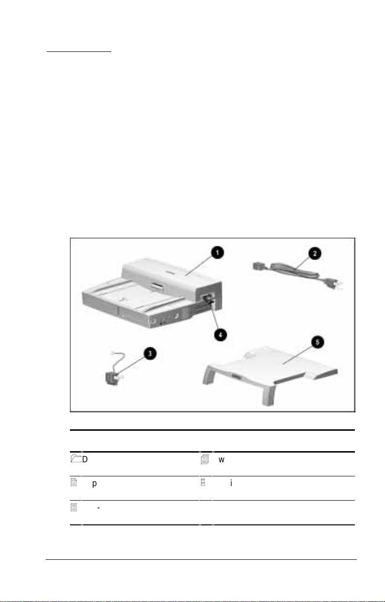
Contents of the Packing Box
Before you begin, make sure you have removed everything fr om
the box. In addition to the Quick Setup poster and documentation
about the desktop expansi on base, the box contains:
Contents of the Packing Box
Desktop expansion base
2
Expansion base power cord
3-to-2-prong plug adapter
3
(Japan only)
Packing Box Contents
4
Two expansion base keys
(shipped inside PC Card slot)
5
Monitor support cover (optional on
some models)
Getting Started 1-1
Page 10
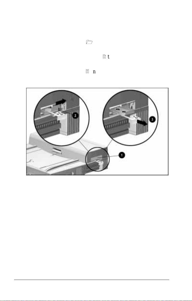
Removing the Keys from the PC Car d Slot
To remove the two desktop expansion base keys fr om the PC Card
slot, follow these steps:
1. Open the PC Card door 1 by swinging it upward from
the bottom.
2. Slide the PC Card security post 2 toward the rear of the
expansion base.
3. Remove the key carrier 3 and keys from the PC Card slot.
4. Close the PC Card door.
Removing the Keys from the PC Card S l ot
1-2 Getting Started
Page 11

Installation Requirements
The desktop expansion ba se can be used with any of the Com pa q
Armada 7000 Families of Personal Computers.
The expansion base a nd the computer can be set up a s a desktop
or tower system.
■
A desktop system must include an external keyboard and
mouse. For quick set up instructions, refer in this chapter to
❏ “Setting Up a D esktop System Without an External
Monitor”
or
❏ “Setting Up a Desktop System with an External Monitor”
NOTE: A monitor support cover is included with some
ArmadaS tation models. To add a monitor support cover to
your system as an optional accessory, refe r to “Worldwide
Telephone Numbers” in Appendix A to cont act your nearest
Compaq authorized dealer, reseller, or service provider.
■
A tower system requires an optional tower stand. For
quick setup instruct ions, refer to Chapter 11, “Setting Up a
Tower System.”
Getting Started 1-3
Page 12
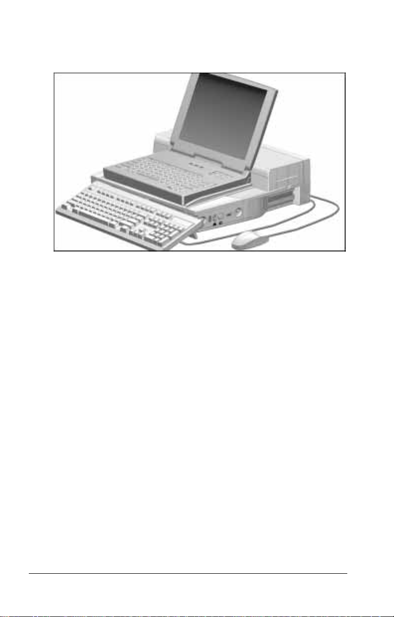
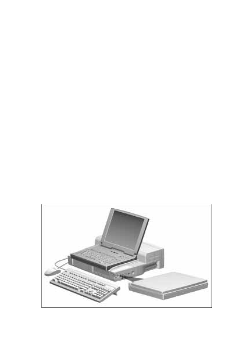
Setting Up a Desktop System
Without an External Monitor
Desktop System without an Ext ernal M oni tor
1-4 Getting Started
Page 13
Connecting the Keyboard and Mouse
To connect the keyboard and mouse to the desktop expansion
base, follow these steps:
1. Place the expansion base on a flat surface near an
electrical outlet.
2. Connect the keyboard to one of the keyboard/mouse
connectors 1.
3. If you have a PS/2-compatible mouse, conne ct it to the
remaini ng keyboard/mouse connector. If you have a serial
mouse, connect it to the serial connector 2.
NOTE: If you are not certain w he ther you have a PS/2-compatible
or a serial mouse, refer to the documentation that came with
the mouse.
Identifying the Keyboard/ M ouse Connect ors and t he S e rial Connect or on the Desktop
Expansion Base
Getting Started 1-5
Page 14
Connecting the Expansion Base Power Cord
To connect the de skt op expansion base to electric al power, follow
these steps:
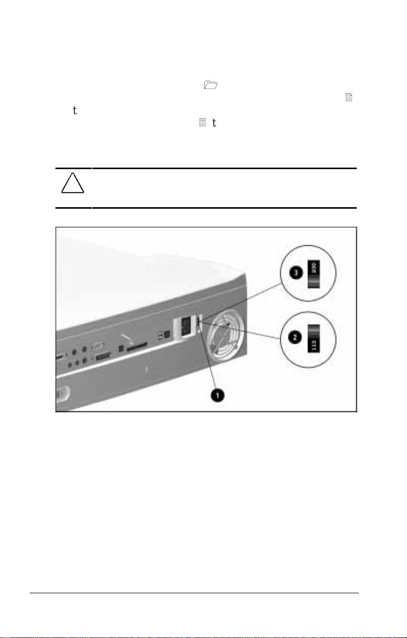
1. Set the voltage select switch 1 to the voltage suppl ied by
your electrical service provider . When 115 VAC is selected 2,
the number 115 i s vi sible on the red portion of the switch.
When 230 VAC is selec t ed 3, the number 230 is visible.
NOTE: To verify the voltage of your electrical supply, contact
your electrical service provider.
CAUTION: Ensure that the voltage select switch is in the correct
position (115 VAC or 230 VAC). Failure to do so will result in
damage to the equipment.
Setting the Volt age Select Switch
1-6 Getting Started
Page 15
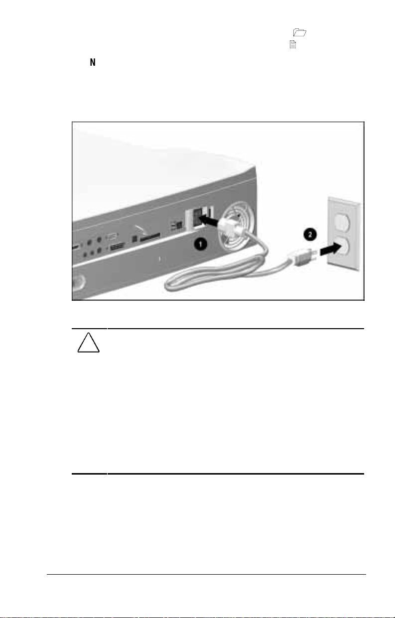
2. Plug the power cord into the power connector 1 on the
expansion base, then into the electrical outlet 2.
NOTE: To plug the expansion base i nt o an outlet in Japan, you
you must first plug the power cord into t he 3-to-2-prong plug
adapter included with the expansion base. Ensure that the
ground wire is connected to a safe earth ground, then plug the
3-to-2-prong plug adapter into the electrical outlet.
Plugging In the Desktop Expansion Base
WARNING: To reduce the risk of personal injury, electric shock,
!
fire, or damage to the equipment:
■
Do not disable the power cord grounding plug. The grounding
plug is an important safety feature.
■
Plug the equipment into a grounded (earthed) electrical outlet
that is easily accessible at all times.
■
Disconnect power from the equipment by unplugging the power
cord from the electrical outlet.
■
Do not place anything on power cords or cables. Arrange them
so that no one may accidentally step on or trip over them. Do not
pull on a cord or cable. When unplugging from the electrical
outlet, grasp the cord by the plug.
Getting Started 1-7
Page 16
Docking the Computer
WARNING: To avoid the risk of personal injury, keep fingers and
!
hands away from the rear of the computer when docking.
CAUTION: Set up a new computer while it is undocked. Do not turn
a computer on for the first time while it is docked.
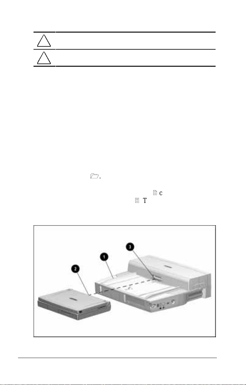
To dock the computer in the desktop expansion base, follow
these steps:
1. Turn off the computer, if it is on. If you are not sure whether
the computer is off or in Hiber nation, turn the comput er on,
then shut it down.
NOTE: For information about docking the computer without
shutting it down, refer to “Preparing to Dock the Computer”
in Chapter 4.
2. Turn off, then disconnect any external equipment connected to
the computer. Disconnect cables to any installed PC Cards.
Disconnect the computer power cord.
3. Slide the computer into the expansion base along the left
alignment gui de 1.
4. Push the computer toward the rear of the expansion base until
the docking connector on the computer 2 contacts the docki ng
connector on the e xpansion base 3. This activates the
motorized docking mechanism, which pulls the computer into
a fully seated connection.
Docking the Computer in the Desktop Expansion B ase
1-8 Getting Started
Page 17
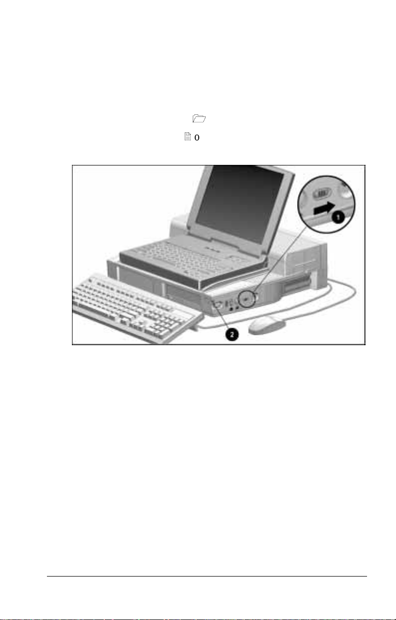
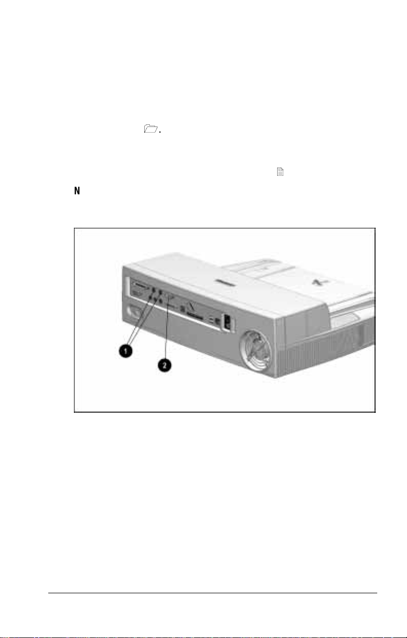
Turning On the System
To turn on power to the system (the desktop expansi on base,
computer, and connected external devices)
■
Slide the power switch on the computer.
or
■
Slide the power switch 1 on the expansion base.
The power/s uspend light 2 on the expansion base turns on when
the system is on.
Turning On the System
Getting Started 1-9
Page 18
Setting Up a Desktop System
with an External Monitor
Desktop System with an Optional External Monitor
1-10 Getting Started
Page 19
Installing the Monitor on a Monitor Support Cover
WARNING: To avoid the risk of personal injury or structural
!
damage to the monitor support cover, do not place a monitor with an
unstable base or a monitor heavier than 55 pounds (25 kilograms)
on the support cover. Place the monitor on a work surface next to
the docking base.
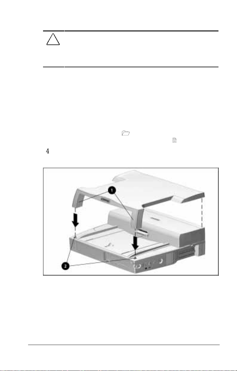
To install an optional external monitor on a monitor support
cover, follow these steps:
1. Ensure that the monitor power switch is turned off.
2. Place the expansion base on a flat surface near an
electrical outlet.
3. Place the monitor support cover on the desktop expansion
base. Ensure that the legs 1 of the monitor support cover fit
securely into the monitor support cover slots 2.
4. Place the base of the monitor on the flat area toward the rear of
the monitor support cover.
Placing the Monitor S upport Cover on t he Deskt op E xpansion B ase
Getting Started 1-11
Page 20
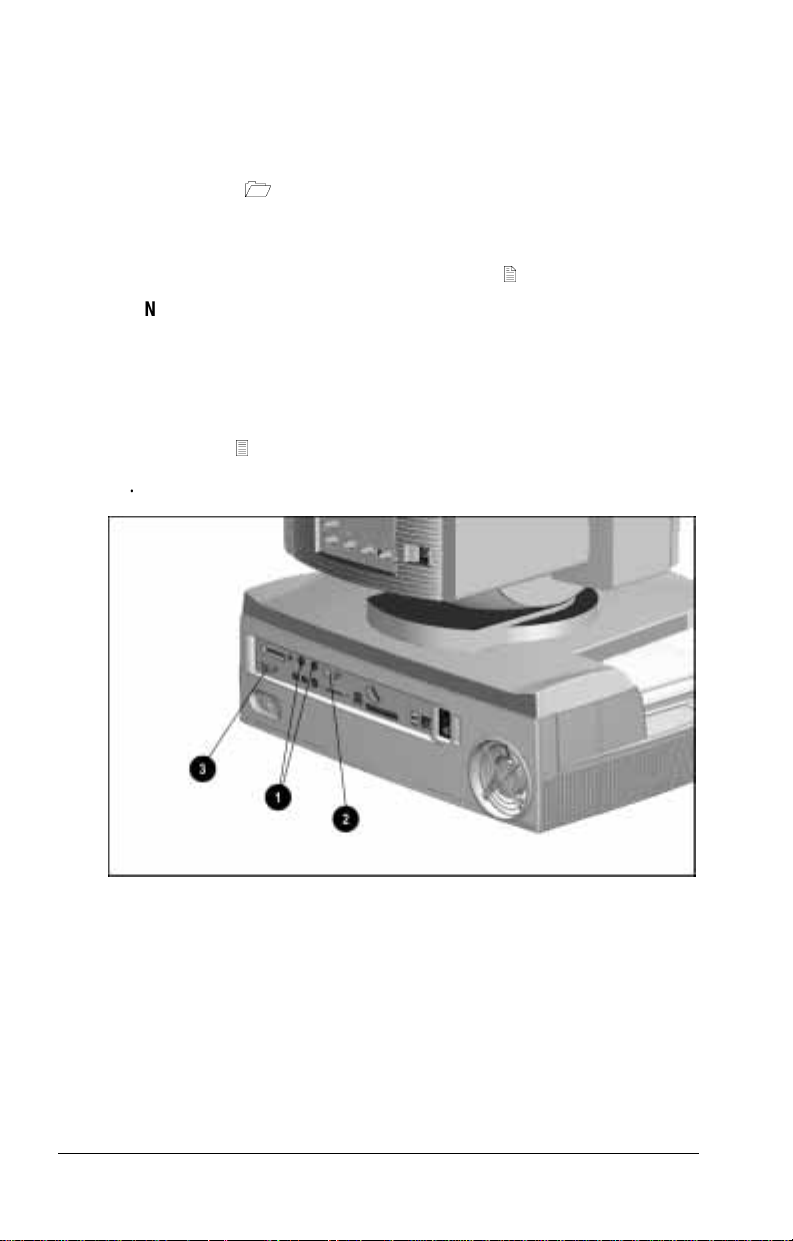
Connecting the Keyboard, Mouse, and Monitor
To connect the keyboard, mouse, and m oni tor to the desktop
expansion base, foll ow t hese steps:
1. Connect the keyboard to one of the keyboard/mouse
connectors 1 on the rear pa nel of the expansion base.
2. If you have a PS/2-compatible mouse, conne ct it to the
remaini ng keyboard/mouse connector. If you have a serial
mouse, connect it to the serial connector 2.
NOTE: If you are not c ertain whether you have a
PS/2-compatible or a serial mouse, refer to the documentation
that came with the mouse.
3. Ensure that the power switch on the external monitor is off.
4. Connect the external monitor cable to the external monitor
connector 3.
5. Plug the external monitor power cord into an electrical outlet.
Identifying the Keyboard/ M ouse Connect ors, S e rial Connect or, and External Monitor
Connector on the Desktop Expansion Base
1-12 Getting Started
Page 21

Completing the Setup
To complete the setup of a desktop system with an external
monitor, follow these steps:
1. Turn off the computer, if it is on.
2. Close the computer, if it i s open.
3. Follow the procedures in the previous section, “Setting Up the
System Without an External Monitor,” for
■
First, “Connecting the Expansion Base Power Cord.”
■
Second, “Doc king the Computer.”
■
Third, “Turning On the System.”
4. Turn on the external monitor power switch.
Getting Started 1-13
Page 22
chapter
2
I
DENTIFYING COMPONENTS
Left Side Component
Left Side Component
Left Side Component
Component Function
Audio bass port Enhances sound.
IMPORTANT:
base is an active component of the expansion base audio system. Do
not place foreign objects in this opening.
The audio bass port molded into the desktop expansion
Identifying Components 2-1
Page 23
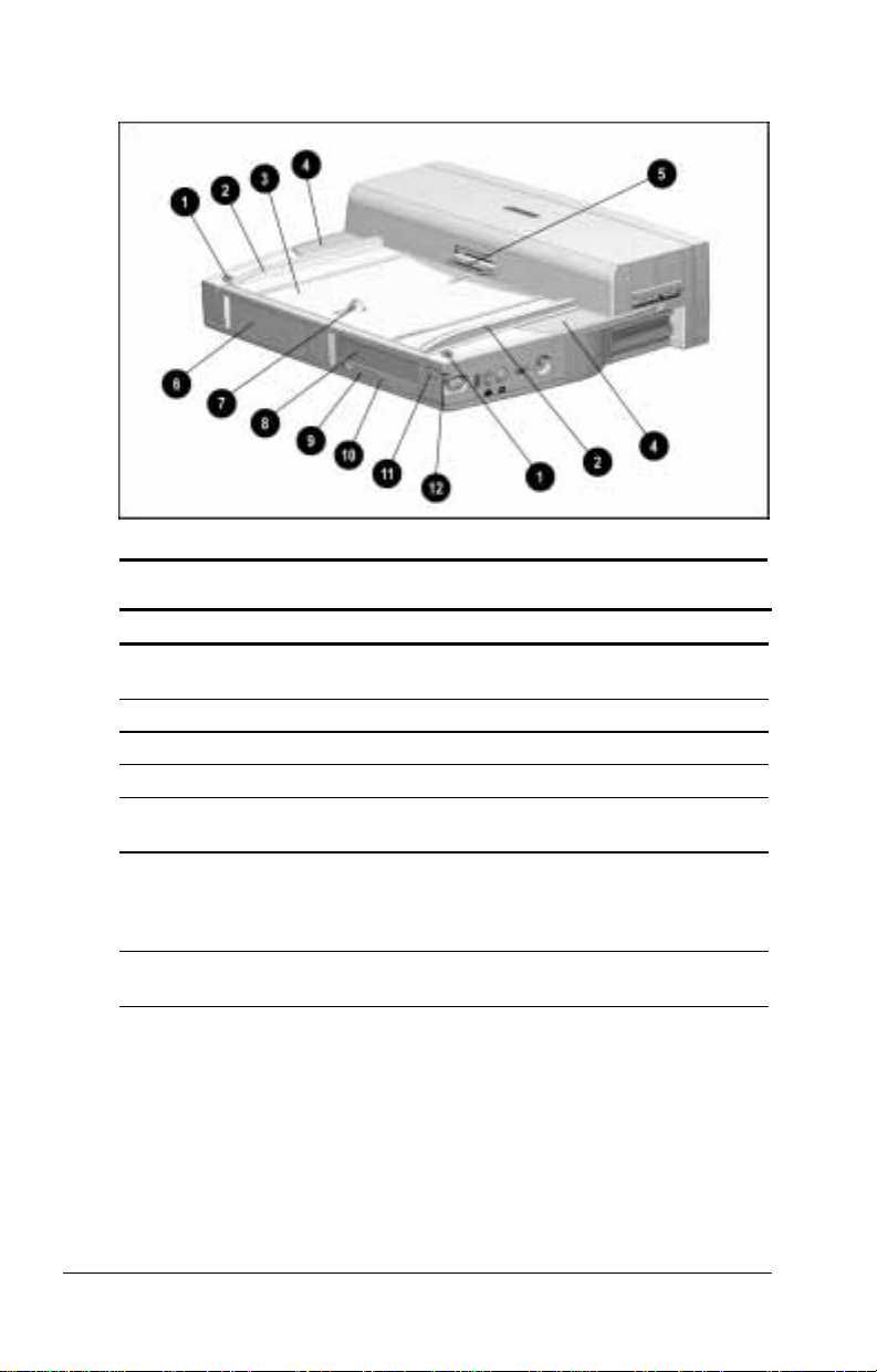
Front and Top Components
Front and Top Components
Front and Top Components
Component Function
1
Monitor support cover
slots (2)
2
Alignment guides (2) Guide computer during docking.
Alignment tray Positions docked computer.
3
4
Stereo speakers (2) Produce high quality stereo sound.
Docking connector Connects to docking connector
5
Half-height bay Supports a standard half-height bay
6
Docking latch Helps secure computer in the
7
Position monitor support cover.
on computer.
device. Can be converted to a
second MultiBay or an
LTE 5000 MultiBay.
expansion base.
Continued
2-2 Identifying Components
Page 24

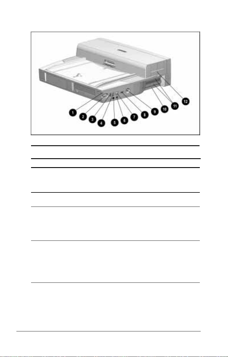
Front and Top Components
Continued
Component Function
MultiBay Supports any MultiBay device that is
8
MultiBay device
9
release latch
MultiBay light Turns on when
:
Suspend button When system is off: Turns system on.
;
Power/suspend light On: System is on.
<
supported by a computer MultiBay.
Releases a device from the MultiBay.
■
A removable drive in the MultiBay
is being accessed.
■
A battery pack in the MultiBay is
charging. (Turns off when the
battery pack is fully charged.)
When system is on: Initiates Suspend.
When system is in Suspend:
Exits Suspend.
Off: System is off.
Blinking: System is in Suspend.
Identifying Components 2-3
Page 25
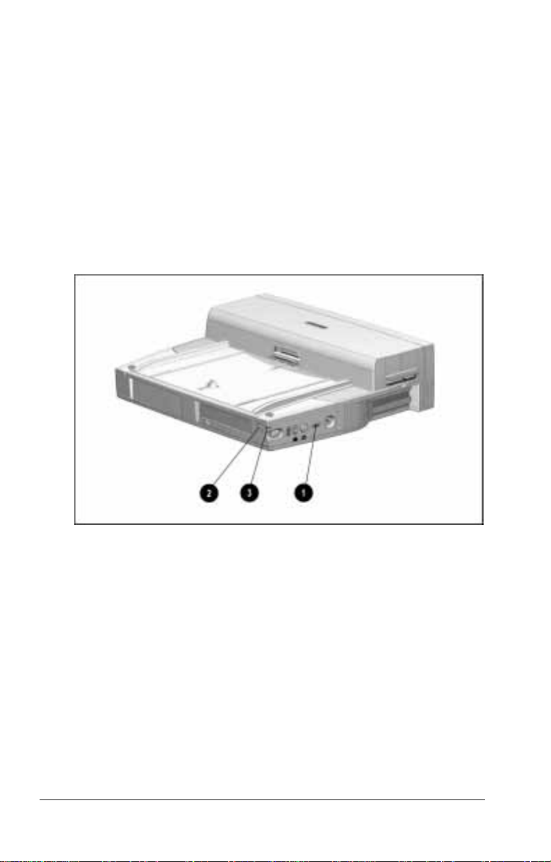
Right Side Components
Right Side Components
Right Side Components
Component Function
Power/suspend light On: System is on.
1
Computer eject button Releases computer from the
2
Infrared port Links to another IrDA-compliant
3
Volume control Adjusts volume on
4
Off: System is off.
Blinking: System is in Suspend.
expansion base.
device for wireless communication.
NOTE: This pass-through connector
functions only when an infraredequipped computer is docked.
■
Expansion base speakers.
■
Optional external speakers,
headphone, or
headset connected to the
expansion base.
Continued
2-4 Identifying Components
Page 26

Right Side Components
Continued
Component Function
5
Headphone jack Connects an optional stereo
headphone or headset.
6
Microphone jack Connects an optional single sound
channel (monaural) microphone.
7
Mute button Mutes volume on
■
Expansion base speakers.
■
Optional external speakers,
headphone, or
headset connected to the
expansion base.
8
Power switch When computer is docked, turns
system power on and off.
When computer is not docked, this
button is disabled.
9
Keylock When a computer is docked,
can secure
■
The computer to the
expansion base.
■
Removable drives and battery
packs in expansion base and
computer MultiBays.
■
A battery pack in a computer
battery bay.
■
PC Cards in the expansion base.
■
Options that are installed in the
expansion base such as
expansion boards or a
100BaseTX Ethernet module.
:
Desktop expansion base
serial number
;
Expansion slot covers (2) Protect slots where optional
<
PC Card door Protects PC Card slots (2).
Expansion base
identification number.
expansion boards can be installed.
Identifying Components 2-5
Page 27
Rear Panel Components
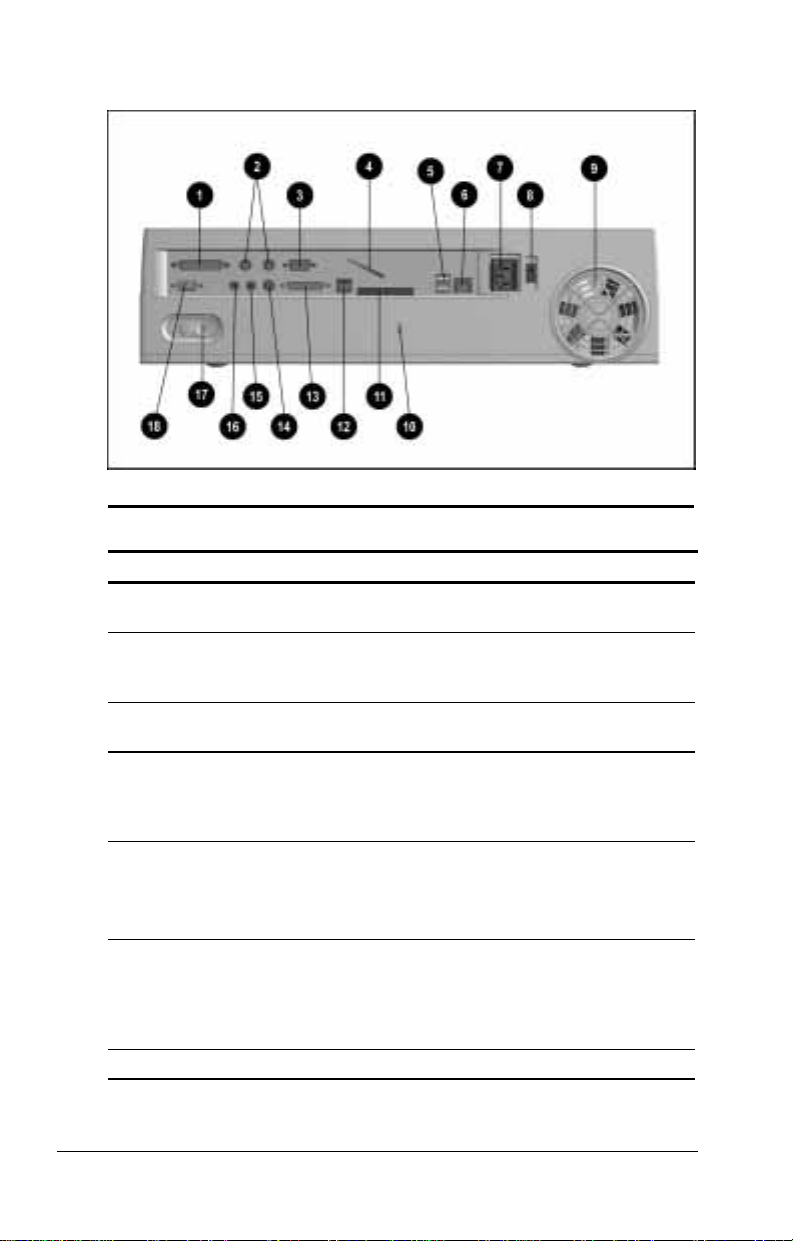
Rear Panel Components
Rear Panel Components
Component Function
1
Parallel connector Connects an optional parallel device
Keyboard/mouse
2
connectors (2)
Serial connector Connects an optional serial device
3
U-bolt Attaches an optional security cable to
4
USB connectors (2) Connect optional USB devices.
5
RJ-45 jack Connects a 10BaseT Ethernet
6
Power connector Connects external AC power.
7
such as a parallel printer.
Connect an optional PS/2-compatible
device such as a keyboard, mouse,
or keypad.
such as a serial mouse.
the expansion base. Accommodates
thicker cables than the security
cable slot.
NOTE: These USB pass-through
connectors function only when a
USB-equipped computer is docked.
network. Can be used with a
100BaseTX Ethernet network if an
optional 100BaseTX Ethernet Module
is installed in the expansion base.
Continued
2-6 Identifying Components
Page 28

Rear Panel Components
Continued
Component Function
Voltage select switch Adjusts expansion base to
8
Fan Circulates air through the expansion
9
Security cable slot Attaches an optional security cable to
:
25-pin connector The availability and use of this pass-
;
RJ-11 jack The availability and use of this pass-
<
MIDI/game connector Connects an optional joystick or
=
External infrared transceiver
>
connector
Stereo line-in jack Connects an optional tape recorder,
?
Stereo line-out jack Connects optional external speakers.
@
Rear panel release latch Releases the rear panel of the
A
External monitor connector Connects an optional external
B
supplied voltage.
base to cool internal components.
the expansion base.
through modem connector varies
regionally. Please refer to
“Regional Differences” at the end of
this chapter.
through modem connector varies
regionally. Please refer to
“Regional Differences” at the end of
this chapter.
MIDI device.
Connects an optional External
Infrared Transceiver.
NOTE: This pass-through connector
functions only when an infraredequipped computer is docked.
tuner, or CD player.
expansion base, allowing access to
the manual release latch and to
internal components.
monitor or overhead projector.
Regional Differences
The desktop expansion base connectors used for modem pass-
through vary by region.
An expansion base purchased for use in North America, Latin
■
America, Japan, or Hong Kong has an RJ-11 connector.
An expansion base purchased for use in Europe or Asia Pacific
■
(except Japan or Hong Kong) has a 25-pin connector.
Identifying Components 2-7
Page 29
chapter
3
G
ETTING CONNECTED
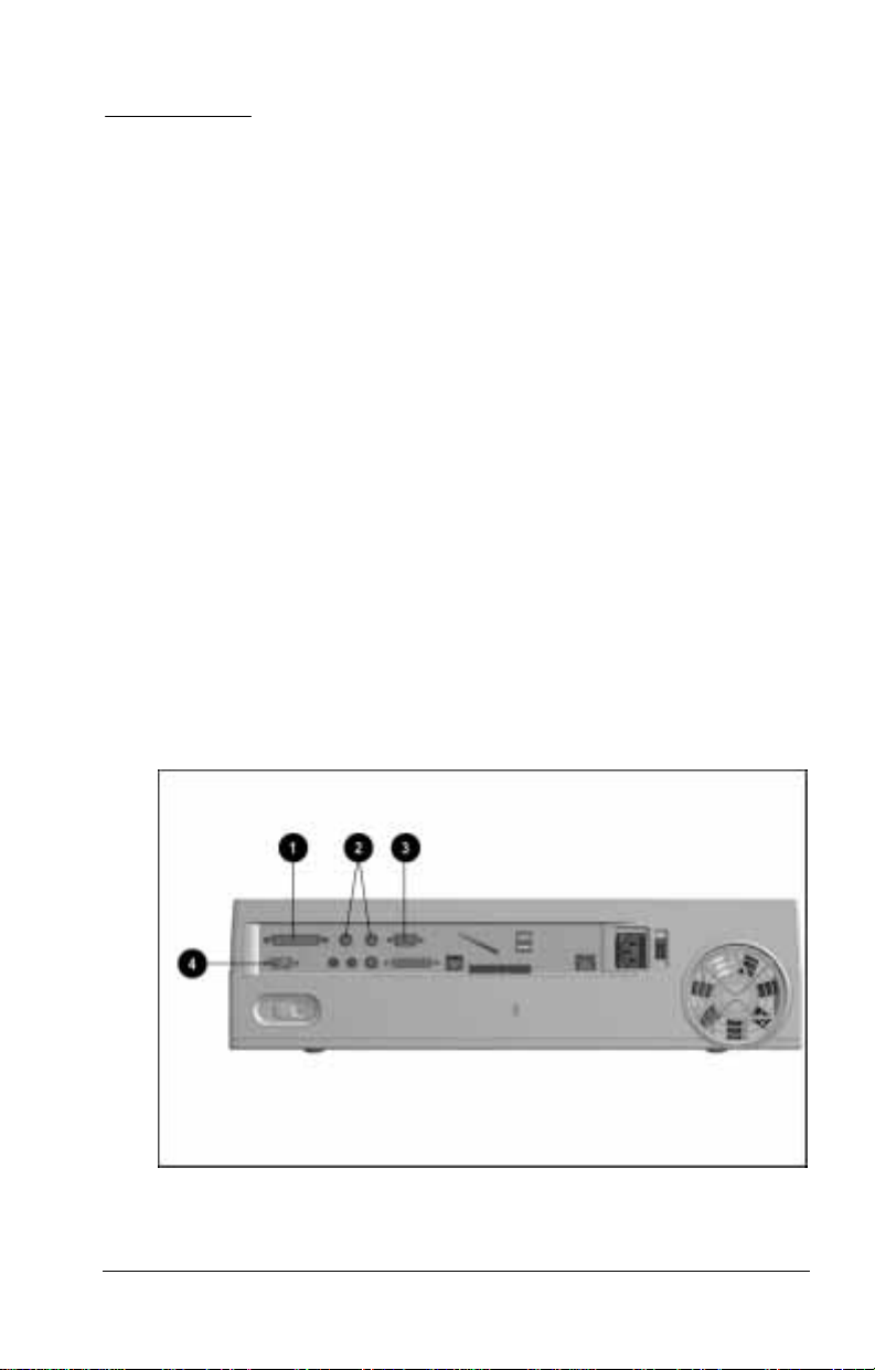
Connecting an External Device
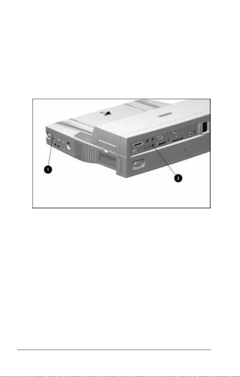
Selecting a Connector
If the device documentation directs to you connect the device to a
connector on the computer, you can connect the device to the
connector with the same name on the desktop expansion base.
For example, if your printer, keyboard, mouse, numeric keypad,
external monitor, or overhead projector documentation instructs
you to connect the device to a parallel, PS/2, serial, or external
monitor connector on your computer, you can connect the device
to the parallel 1, keyboard/mouse (PS/2) 2, serial 3, or external
monitor connector 4 on the expansion base.
Identifying Connectors
Getting Connected 3-1
Page 30

Connecting an External Device to the System
To connect an external device to the system, follow these steps:
1. If the computer is docked turn it off.
2. If the external device is on, turn it off, then disconnect it from
external power.
3. If the external device is connected to the computer,
disconnect it.
4. Connect the external device cable to a connector on the
expansion base.
5. If applicable, plug the power cord of the external device into
an electrical outlet.
6. If applicable, turn on the power switch of the external device.
7. Turn on the system with the computer power switch or the
expansion base power switch.
3-2 Getting Connected
Page 31

Using an External Device in the System
Audio Equipment
When the computer is docked, the computer speakers are disabled,
and sound plays as follows through the desktop expansion base.
Sound Playback
Connector Function
1
Headphone jack Connects a headphone or headset.
Sound plays in stereo from the headphone
or headset.
2
Microphone jack Connects a single sound channel microphone.
Sound plays from both expansion base speakers.
3
Stereo line-out
jack
4
Stereo line-in
jack
Connects external speakers.
Sound plays in stereo from the external speakers
and from both expansion base speakers.
Connects a tape recorder, tuner, or audio
CD-player.
Sound plays in stereo from both expansion
base speakers.
Identifying Audio Connectors on the Desktop Expansion Base
Getting Connected 3-3
Page 32

WARNING:
!
volume control before putting on headphones.
To reduce the risk of personal injury, turn down the
System volume settings
Are stored in the computer.
■
Must be set while the computer is docked.
■
Do not affect system beeps.
■
To turn system sound on or off, toggle the mute button 1. To
adjust volume, press the top or bottom of the volume control 2.
To increase volume from an external device, increase both
NOTE:
the system volume and the device volume.
Identifying the Mute Button and Volume Control on the Desktop Expansion Base
3-4 Getting Connected
Page 33

External Keyboard
The hotkey commands used on the computer keyboard cannot be
used on
An external keyboard used with an Armada 7700 or lower
■
computer model.
An external keyboard used with an Armada 7800 computer
■
model if a USB driver is loaded into the system and a USB
connector is used to connect the keyboard to the system.
To execute a hotkey command from an external keyboard used
with an Armada 7800 computer that does not have a USB driver
loaded and is not connected by USB, follow these steps:
1. Press the
Scroll Lock
2. Immediately after pressing the
key twice consecutively within a second.
Scroll Lock
key twice, press the
second key only of the hotkey combination. For example, if
you want to use the
key twice, then press only
Lock
If you do not press the second key of a hotkey combination
NOTE:
within five seconds after pressing the
must again press the
Scroll Lock
hotkey command, press the
Fn+F4
F4.
Scroll Lock
key twice to reactivate the hotkey
Scroll
key twice, you
command feature.
External Monitor or Overhead Projector
If an external monitor or overhead projector remains blank after it
warms up, toggle the
hotkey on the computer to switch the
Fn+F4
display from computer display, to external monitor or overhead
projector display, to simultaneous display.
Joystick or MIDI Device
MIDI software and a MIDI adapter cable are required to operate
MIDI-compatible equipment through the desktop expansion base.
To connect a MIDI device to the MIDI/game connector on the
expansion base, follow these steps:
1. Connect the MIDI adapter cable to the MIDI device, then to
the expansion base.
2. Plug the MIDI device power cord into an electrical outlet.
The MIDI/game connector on the expansion base accommodates a
paired MIDI adapter cable with connectors for two devices.
Getting Connected 3-5
Page 34

USB Equipment
The two USB pass-through connectors on the desktop expansion
base function only when a USB-equipped computer is docked.
The connectors then function as powered hubs and can support
any USB device or combination of USB devices that is supported
by the computer.
When used with an Armada 7800 computer that has a USB
NOTE:
driver loaded, an external keyboard connected to a USB connector
on the computer or on the expansion base will not support hotkey
commands, initiating QuickLock/QuickBlank with
Ctrl+Alt+L,
exiting QuickLock/QuickBlank with a power-on password.
Connecting a Modem
The modem connector on the desktop expansion base is a passthrough connector. It functions only when a modem-equipped
computer is docked. It supports the same modem speeds and
features as the modem in the computer.
If the expansion base was purchased for use in North America,
■
Latin America, Japan, or Hong Kong, the modem connector is
an RJ-11 jack 1.
If the expansion base was purchased for use in Europe or Asia
■
Pacific (except Japan or Hong Kong), the modem connector is
a 25-pin connector 2.
or
Identifying an RJ-11 Connector or a 25-Pin Connector on the Desktop Expansion Base
3-6 Getting Connected
Page 35

Connecting an RJ-11 Jack
An RJ-11 jack can be connected to any standard (analog)
telephone wall jack, hotel data line, or office fax machine or
modem line in North America, Latin America, Japan, or
Hong Kong.
The connection requires a telephone cable such as the one
included with some integrated modem-equipped computers.
To connect the RJ-11 jack to an analog line, follow these steps:
1. Plug one end of a telephone cable into the RJ-11 jack on the
expansion base.
2. Plug the other end of the cable into an analog jack.
Connecting a 25-Pin Connector
A 25-pin connector can be connected to any standard telephone
wall jack in Europe or Asia Pacific.
The connection requires a country-specific modem cable, such as
the one included with some integrated modem-equipped
computers.
To connect the 25-pin connector to a telephone line, follow
these steps:
1. Connect the 25-pin connector on the country-specific modem
cable to the 25-pin connector on the expansion base.
2. Plug the other end of the cable into a telephone jack.
You need a country-specific modem cable for each country
NOTE:
in which you want to connect the expansion base. To purchase a
country-specific modem cable for use with a 25-pin connector or a
telephone cable for use with an RJ-11 jack, refer to “Worldwide
Telephone Numbers” in Appendix A for the name of the nearest
Compaq authorized dealer, reseller, or service provider.
Getting Connected 3-7
Page 36
Establishing an Infrared Link
The pass-through infrared port 1 and the pass-through external
infrared transceiver connector 2 on the desktop expansion base
function only when an infrared-equipped computer is docked.
Both support all the infrared capabilities of the computer.
Compaq infrared computers are IrDA-compliant (4 Mbps
NOTE:
standard). Infrared performance may vary depending on
performance of infrared peripherals, distance between infrared
devices, and applications used.
Identifying the Infrared Port and the External Infrared Transceiver Connector on the
Desktop Expansion Base
3-8 Getting Connected
Page 37
Linking with the Infrared Port
When the computer is docked in the desktop expansion base
The infrared port on the computer is disabled.
■
The infrared port on the desktop expansion base is enabled.
■
To position the infrared port for an infrared link to an IrDAcompliant device, do the following:
Ensure that no objects block the line-of-sight path between the
■
infrared ports.
Position the two devices so that the infrared ports face each
■
other at a distance no greater than 1.5 feet (about 0.5 meter).
Aim the ports directly at each other. The maximum capture
■
angle is 30 degrees. Do not point one port more than
15 degrees off the center line from the other port.
Shield the ports from direct sunlight, flashing incandescent
■
light, and energy-saving fluorescent light.
During a transmission
■
Do not allow remote control units, such as wireless
❏
headphones or other audio devices, to point at the ports.
Do not disrupt the infrared beam.
❏
Do not move the devices.
❏
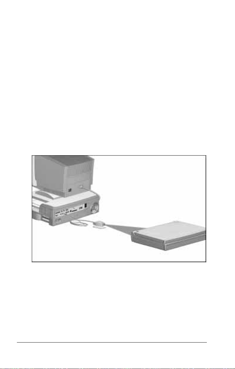
Transmitting Data from the System to Another IrDA-Compliant Computer
Getting Connected 3-9
Page 38
Linking with an Optional External Infrared Transceiver
You can use an optional External Infrared Transceiver to
Adjust the direction of infrared transmissions without moving
■
the desktop expansion base.
Increase the distance of infrared transmissions by the length of
■
the transceiver cable.
When an optional External Infrared Transceiver is connected to
the desktop expansion base
The infrared ports on the computer and the expansion base
■
are disabled.
The external infrared transceiver connector on the expansion
■
base is enabled.
To connect an External Infrared Transceiver to the system,
connect the transceiver cable to the external infrared transceiver
connector on the expansion base.
Using an Optional External Infrared Transceiver
3-10 Getting Connected
Page 39

Connecting to an Ethernet Network
To connect the system to a 10BaseT Ethernet network
First, connect the system to the network with a network cable.
■
Second, install the drivers for your operating system.
■
To connect the system to a 100BaseTX Ethernet network, you
must first install an optional 100BaseTX Ethernet Module. For
information, refer to “Worldwide Telephone Numbers” in
Appendix A for a Compaq authorized dealer, reseller, or service
provider near you.
Installing an optional 100BaseTX Ethernet Module in a
NOTE:
system connected to a 10BaseT Ethernet network will not affect
system or network speed.
Getting Connected 3-11
Page 40
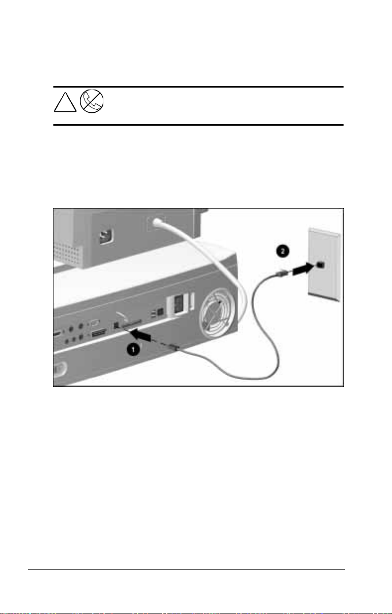
Connecting a Network Cable
This connection requires an unshielded twisted pair cable with
RJ-45 jacks at each end. Request the cable from your network
administrator or authorized service provider.
WARNING:
!
To connect the cable to the desktop expansion base and the
network jack, follow these steps:
1. Connect the cable to the RJ-45 1 jack on the expansion base.
2. Connect the other end of the cable to the network jack 2.
damage to the equipment, do not plug a telephone cable into
the Ethernet RJ-45 jack.
To reduce the risk of electric shock, fire, or
Connecting the System to an Ethernet Network
3-12 Getting Connected
Page 41

Installing Network Drivers
Before you can log onto the network, network drivers specific to
your computer model and operating system must be installed.
If you are running Windows 95 on an Armada 7800 computer
■
model, network drivers are preinstalled.
If you are running Windows NT on an Armada 7800 computer
■
model, you must install network drivers.
If you are using an Armada 7700 or an Armada 7300
■
computer model, you must update the network drivers
preinstalled on your computer.
For configuration information specific to your network,
NOTE:
consult your Network Administrator.
Obtaining Drivers
You can obtain network drivers and instructions for installing
them from the
CPQNET directory preinstalled on some computers at
■
C:\CPQNET.
Compaq Internet site at www.compaq.com.
■
■
Compaq Support Software CD
■
Armada Integrated Netflex-3 Ethernet Drivers
Diskettes 1
and 2. These diskettes are included with your
.
ArmadaStation. They contain network drivers for
Armada 7800 computer models running Windows 95.
❏
All Armada 7700 computer models.
❏
All Armada 7300 computer models.
❏
To ensure that you install the latest drivers for your
NOTE:
operating system, go to the Compaq Internet site or refer to
“Worldwide Telephone Numbers” in Appendix A for information
about contacting your nearest Compaq dealer, reseller, or service
provider to obtain the latest
Compaq Support Software CD
.
Installing Drivers from CPQNET
To access the network drivers and installation instructions in the
CPQNET directory, follow these steps:
Getting Connected 3-13
Page 42

1. Connect the desktop expansion base to the network with a
network cable.
For connection instructions, refer to the previous
NOTE:
section, “Connecting a Network Cable.”
2. Dock the computer.
3. Turn on the system with the power switch on the computer or
the power switch on the expansion base.
4. Open the CPQNET directory.
5. Open the subdirectory for the network operating system used
on the computer.
6. Open the Readme.txt file in the subdirectory.
7. Follow the instructions in the Readme.txt file for installing
drivers for the Compaq Integrated Netflex-3 Controller.
3-14 Getting Connected
Page 43

chapter
4
D
OCKING AND UNDOCKING
Preparing to Dock the Computer
When the Computer Is Running Windows 95
If the computer is running Windows 95, you can dock while the
computer is on, off, or in Suspend or Hibernation.
Docking While the Computer Is On or in Suspend
If the computer is docked while it is in Suspend, the desktop
■
expansion base turns on the computer and your information
returns to the screen.
If the computer is docked while it is on or in Suspend, the
■
system recognizes most drives, PC Cards, and expansion
boards installed in the expansion base.
If the system does not recognize a particular drive,
NOTE:
PC Card, or expansion board, restart the computer after it
is docked.
Docking While the Computer Is in Hibernation
CAUTION:
the loss of unsaved information.
If the computer is docked while in Hibernation:
Any battery packs in the computer begin to charge.
■
The system will not recognize devices installed in the
■
expansion base until the computer is restarted.
A Hibernation prompt appears on the screen.
■
Docking a computer that is in Hibernation can result in
Docking and Undocking 4-1
Page 44

The Hibernation prompt asks whether you want to restart the
computer and lose unsaved data or to abort the docking process
and preserve unsaved data.
To restart the computer, press
■
To exit Hibernation and return your work to the screen, follow
■
F1.
these steps:
1.
Press
F2.
2. Undock the computer.
3. Plug the computer into an external power source.
4. Turn on the computer by sliding the power switch.
When the Computer Is Not Running Windows 95
If the computer is running an operating system other than
Windows 95, turn off the computer before your dock it.
If you dock a computer running Windows NT 4.0 while it is
NOTE:
in Suspend, the desktop expansion base will turn on the computer,
but the system will not recognize any drives, PC Cards, or
expansion boards installed in the expansion base until you restart
the computer.
4-2 Docking and Undocking
Page 45

Docking the Computer
WARNING:
!
hands away from the rear of the computer when docking.
CAUTION:
is docked.
Compaq recommends that you save and close all files and
applications before docking.
To dock the computer in the desktop expansion base, follow
these steps:
1. Turn off the computer, unless it is running Windows 95.
2. Turn off then disconnect any external equipment connected to
the computer. Disconnect cables to any installed PC Cards.
3. Slide the computer into the expansion base along the left
alignment guide
4. Push the computer toward the rear of the expansion base until
the docking connector on the computer 2 contacts the docking
connector on the expansion base 3. This activates the
motorized docking mechanism, which pulls the computer into
a fully seated connection.
To avoid the risk of personal injury, keep fingers and
Do not turn the computer on for the first time while it
1.
Docking the Computer in the Desktop Expansion Base
Docking and Undocking 4-3
Page 46
Managing System Power
Turning On the System
If you dock a computer while it is off, you can turn the system
on by
Sliding the power switch on the computer.
■
Sliding the power switch 1 on the desktop expansion base.
■
Pressing the suspend button 2 on the desktop expansion base.
■
The power/suspend light 3 on the expansion base turns on when
the system is on, turns off when the system is off, and blinks when
the system is in Suspend.
Identifying the Power Switch, Suspend Button, and Power/Suspend Light on the
Desktop Expansion Base.
Using the Power Switch
The power switch does
off. The expansion base is on whenever it is connected to
external power.
When a computer is docked, the power switch turns the
■
system (the computer, the expansion base, and all connected
external devices) on and off.
When no computer is docked, the power switch does
■
not function.
4-4 Docking and Undocking
turn the expansion base on and
not
Page 47

Using the Suspend Button
The suspend button functions only when a computer is docked.
You can use the suspend button on the expansion base as you do
the suspend button on the computer in these ways:
When the system is on, press the suspend button to
■
initiate Suspend.
When the system is in Suspend, press the suspend button to
■
exit Suspend.
The suspend button on the expansion base differs from the
suspend button on the computer in these ways:
If you have docked a computer while it is off, pressing the
■
suspend button on the expansion base turns the system on.
The suspend button on the expansion base cannot
■
be used with the
initiate Hibernation.
Because power is continuously available to a docked
NOTE:
computer, Hibernation cannot be initiated while the computer
is docked.
key on the computer keyboard to
Fn
Docking and Undocking 4-5
Page 48

Undocking the Computer
Automatic Undocking of the Computer
To undock the computer from the desktop expansion base using
the motorized undocking mechanism, follow these steps:
1. Unlock the expansion base keylock if it is locked.
For keylock information, refer to Chapter 5, “Securing
NOTE:
the System.”
2. Turn off the computer, if necessary, by sliding the power
switch on the computer or the power switch 1 on the
expansion base.
If the computer is running Windows 95, you can undock the
■
computer while it is on, off, or in Suspend.
If the computer is running an operating system other than
■
Windows 95, turn off the computer before you undock it.
3. Turn off then disconnect any external equipment connected to
the computer. Disconnect cables to any installed PC Cards.
4. Close the computer, if it is open.
5. Press the computer eject button 2 on the expansion base. This
activates the motorized docking mechanism, which pushes the
computer away from the expansion base and disconnects the
docking connector on the computer 3 from the docking
connector on the expansion base 4.
4-6 Docking and Undocking
Page 49

Undocking the Computer from the Desktop Expansion Base
If you press the computer eject button immediately after
NOTE:
shutting down a computer running Windows 95, there may be
a slight delay before the computer is pushed away from the
expansion base. Windows 95 uses this time to perform a safe
shutdown of the system.
6. When the undocking process is complete, slide or lift the
computer out of the expansion base.
Docking and Undocking 4-7
Page 50

Manual Undocking of the Computer
The motorized undocking mechanism requires electricity. If
power becomes unavailable to the desktop expansion base while
the computer is docked, you can release the computer from the
expansion base by using the manual release latch behind the rear
panel of the expansion base.
Before You Begin
To prepare the system for a manual release, follow these steps:
1. Remove the external monitor and monitor support cover,
if applicable.
2. Save all files and applications, then turn off the computer.
3. Unlock the expansion base keylock, if applicable.
For keylock information, refer to Chapter 5, “Securing
NOTE:
the System.”
4. Turn off all external devices connected to the expansion base.
5. Disconnect all cables and the power cord from the
expansion base.
4-8 Docking and Undocking
Page 51

Removing the Rear Panel
To remove the rear panel, follow these steps:
1. Position the expansion base with the rear panel facing you.
2. Slide the rear panel release latch left to the open position.
Sliding the Rear Panel Release Latch to Release the Rear Panel
3. Using both hands, grasp the bottom sides of the rear panel and
swing the bottom out and up until it disengages.
Removing the Rear Panel
4. When you feel the rear panel detach from the top cover of the
expansion base, lift it up and away from the expansion base.
Docking and Undocking 4-9
Page 52

Releasing the Computer from the
Desktop Expansion Base
1. Slide the manual release latch to the right.
Sliding the Manual Release Latch to the Right
2. Pull the computer away from the expansion base along the left
alignment guide.
3. Replace the rear panel by inserting the tabs on the top of the
rear panel into the slots in the top cover. When the tabs are in
the slots, pivot the bottom of the rear panel downward until it
is seated.
4. Secure the rear panel by moving the rear panel release latch
right to the closed position.
5. Reconnect the power cord and all external device cables to the
expansion base.
4-10 Docking and Undocking
Page 53

chapter
5
S
ECURING THE SYSTEM
Managing System Security
The computer, the desktop expansion base, and most removable
devices installed in them can be locked together with the keylock.
The system can then be secured to a fixed or heavy object with an
optional cable lock.
When the expansion base is locked with the keylock
A computer can be docked without unlocking the keylock.
■
This feature enables you to access data in expansion base
drives even if you have misplaced your expansion base key(s).
A computer cannot be undocked until the keylock is unlocked.
■
This feature prevents an unauthorized user from accessing
expansion base data without your knowledge.
Two keys to the expansion base keylock ship inside the PC Card
slot. The keys are identical; the second is included as a spare.
Securing the System 5-1
Page 54

Locking Components with the Keylock
Locking the keylock secures the system as follows:
The motorized undocking mechanism is disabled.
■
The computer is anchored to the expansion base by the
■
docking latch.
The MultiBay device release latches on any MultiBays
■
and battery bays in the computer and the expansion base
are disabled.
The PC Card security post on the expansion base is locked
■
in place.
The rear panel release latch is disabled. This denies access to
■
Any expansion boards installed in the expansion base.
❏
A 100BaseTX Ethernet Module or other component
❏
installed on the input/output (I/O) board of the
expansion base.
The manual release latch used to manually disconnect the
❏
computer from the expansion base.
Locking the keylock does not secure the following items:
PC Cards in the computer.
■
Diskettes or CDs in the computer or the expansion base.
■
5-2 Securing the System
Page 55

Locking and Unlocking the Keylock
To lock or unlock the system with the keylock, follow these steps:
1. If you are locking the system and want to secure a PC Card
installed in the expansion base, position the PC Card security
post so that it blocks access to the PC Card slots.
Positioning the PC Card Security Post
The keylock locks the PC Card security post in its current
NOTE:
position. If the system is locked while the PC Card security post is
in front of the PC Card slots, installed PC Cards are secured. If the
system is locked while the security post is on the far right of the
PC Card slots, installed PC Cards are not secured.
Securing the System 5-3
Page 56
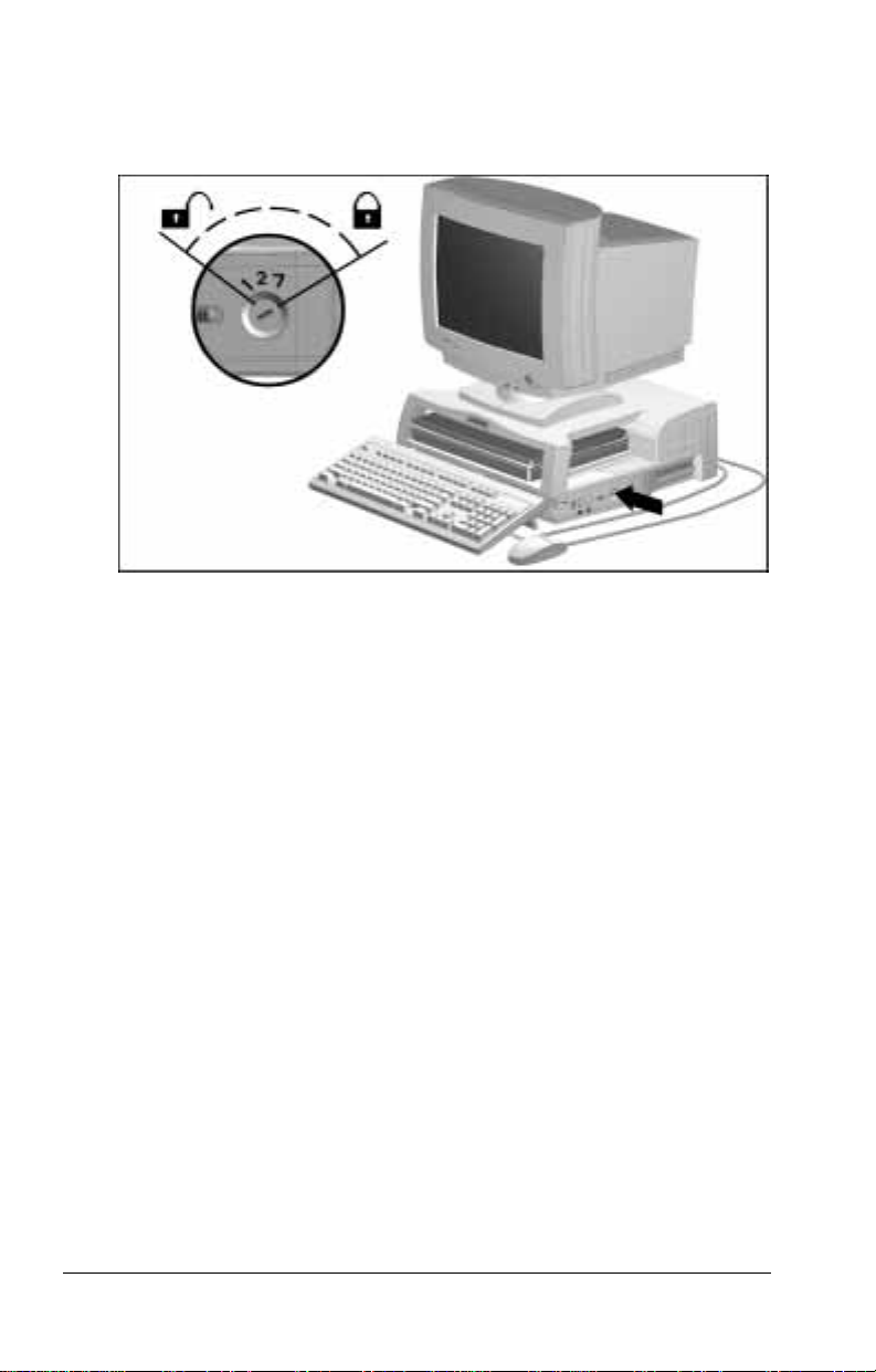
2. Insert the key in the keylock.
3. Turn the key 120 degrees clockwise to lock the system. Turn
the key 120 degrees counterclockwise to unlock the system.
Desktop Expansion Base Keylock
Replacing a Missing Key
To replace a missing key, contact the Fort Lock Corporation:
Fort Lock Corporation
3000 North River Road
River Grove, IL 60171
(708) 458-1100
Report the loss and the numbers on your keylock, and your key
will be replaced.
5-4 Securing the System
Page 57

Attaching an Optional Cable Lock
To connect a Kensington Cable lock to the security cable slot
follow the instructions included with the lock.
A Kensington MicroSaver Security System cable lock
NOTE:
(Model 64068) is available from Kensington Microware Ltd. or
major resellers worldwide.
To connect a larger cable to the U-bolt 2, follow these steps:
1. Ensure that one end of the cable fits through the U-bolt.
2. Loop the cable around a fixed or heavy object.
3. Extend one end of the cable through the U-bolt.
4. Lock the ends of the cable together using an external padlock
or the locking device attached to the cable.
1,
Attachments for an Optional Cable Lock
Securing the System 5-5
Page 58

chapter
6
C
HARGING BATTERY PACKS
Charging a Battery Pack
A battery pack begins to charge as soon as it is inserted into a
desktop expansion base MultiBay when
The computer is not docked.
■
The computer is docked and does not contain any other battery
■
packs that are waiting to be charged.
If the docked computer contains other battery packs that are
waiting to be charged, all battery packs in the system charge in the
sequence described in your computer documentation.
While a battery pack is charging in an expansion base MultiBay,
the expansion base MultiBay light turns on. When the battery
pack is fully charged, the MultiBay light turns off.
Location of the MultiBay Light
Charging Battery Packs 6-1
Page 59

Inserting a Battery Pack into a MultiBay
To insert a battery pack into a desktop expansion base MultiBay,
follow these steps:
1. Determine the model of the battery pack.
An Armada 7700 battery pack has a rectangular label that
■
partially covers the top of the battery pack.
An Armada 7300 battery pack has a large label that covers
■
the top of the battery pack.
2. Unlock the expansion base keylock.
3. Insert the battery pack with the connector
Insert an Armada 7700 battery pack label side up.
■
Insert an Armada 7300 battery pack label side down.
■
4. Push the battery pack into the MultiBay until it is seated and
the MultiBay device release latch 2 slides to the right.
1 facing in.
Inserting a Battery Pack into a Desktop Expansion Base MultiBay
Removing a Battery Pack from a MultiBay
To remove a battery pack from an expansion base MultiBay,
follow these steps.
1. Unlock the expansion base keylock.
2. Slide the MultiBay device release latch to the left.
3. Pull the battery pack out of the MultiBay.
6-2 Charging Battery Packs
Page 60

chapter
7
U
SING REMOVABLE DRIVES
Customizing the Device Bays
The desktop expansion base has two standard half-height bays.
Both can support any removable device that is supported by
the computer.
The right bay is converted to a MultiBay.
■
A removable Armada 7000 Half-Height MultiBay Adapter
❏
is preinstalled in this bay.
To convert this bay to an LTE 5000 MultiBay, replace the
❏
Armada 7000 MultiBay Adapter with an optional LTE
5000 Half-Height MultiBay Adapter.
To convert this bay to a half-height drive bay, replace the
❏
Armada 7000 MultiBay Adapter with an optional halfheight drive.
The left bay is vacant.
■
To convert this bay to a second MultiBay, install an
❏
optional Armada 7000 Half-Height MultiBay Adapter.
To convert this bay to an LTE 5000 MultiBay, install an
❏
optional LTE 5000 Half-Height MultiBay Adapter.
To convert this bay to a half-height drive bay, install an
❏
optional half-height drive.
Expansion base half-height bays as shipped support IDE
■
devices only. To use a SCSI device externally or in a halfheight bay, install a SCSI controller.
For information about installing a half-height bay device, refer to
Chapter 10, “Installing and Removing a Half-Height Bay Device.”
For information about installing a SCSI controller, refer to
Chapter 9, “Installing and Removing an Expansion Board.”
Using Removable Drives 7-1
Page 61

Caring for Removable Drives
Removable drives are fragile components that must be handled
with care.
To prevent damage to the computer, damage to a
CAUTION:
removable drive, or loss of information, observe these precautions:
■
■
■
■
■
■
■
■
■
■
Before removing or inserting a hard drive, shut down the
computer. If you are unsure whether the computer is off or in
Hibernation, turn the computer on, then shut it down.
Before removing a diskette drive, ensure that a diskette is
the drive.
Before removing a CD-ROM drive, ensure that a compact disc is
in the drive and that the CD-ROM tray is closed.
not
Before handling a drive, ensure that you are discharged of static
electricity. While handling a drive, avoid touching the connector.
For more information about preventing electrostatic damage,
refer to Appendix C.
Handle a drive carefully; do not drop it.
Avoid exposing a hard drive to products that have magnetic fields
such as monitors or speakers.
Avoid exposing a drive to temperature extremes.
Avoid exposing a drive to liquids. Do not spray it with cleaners.
Do not use excessive force when inserting a drive into a
drive bay.
If a drive must be mailed, place the drive into a bubble-pack
mailer or other suitable protective packaging and label the
package “Fragile: Handle With Care.”
not
in
7-2 Using Removable Drives
Page 62

Adding Drives to the System
Selecting Supported Drives
A desktop expansion base MultiBay can accommodate
■
Any drive that can be used in any computer in the Armada
❏
7000 Family of Personal Computers.
Any secondary-capable hard drive that can be used in an
❏
LTE 5000 or LTE Elite computer model.
An expansion base LTE 5000 MultiBay can accommodate
■
Any diskette or CD-ROM drive that can be used in an
❏
LTE 5000 computer model.
Any secondary-capable hard drive that can be used in an
❏
LTE 5000 or LTE Elite computer model.
A secondary-capable hard drive that can be used in an LTE 5000
or LTE Elite computer model displays this symbol:
A secondary-capable hard drive displaying this symbol can be
used in the expansion base to store or transfer data files. However,
because drivers for these hard drives are not preinstalled on the
computer, you cannot start (boot) the system from them.
You can prevent an accidental startup from a secondary-
NOTE:
capable hard drive by disabling MultiBoot. For instructions, refer
to the Boot Management section of your computer documentation.
CAUTION:
an LTE 5000 or LTE Elite computer can result in loss of data and
damage to the system.
Attempting to boot from a hard drive that can be used in
Combining Drives
The system (the desktop expansion base, computer, and all
connected devices) supports any combination of drives and drive
locations except the following: No more than two diskette drives
can be supported at one time. The two diskette drives can be
inserted in any two bays in the system.
Using Removable Drives 7-3
Page 63

Using Drive Adapters
Selecting a Drive Adapter
Some removable drives must be inserted into adapters or carriers
before being inserted into an expansion base MultiBay or LTE
5000 MultiBay. Refer to the following table to determine what
adapters are needed to insert drives into your expansion base bays.
Selecting a Drive Adapter
Which can be
To insert
this drive
CD-ROM drive Armada 7800
Diskette drive Armada 7800
Hard drive Armada 7800
CD-ROM drive Armada 7300 MultiBay Armada 7000
Diskette drive Armada 7300 MultiBay Armada 7000
Secondarycapable
hard drive
CD-ROM drive LTE 5000 LTE 5000
Diskette drive LTE 5000 LTE 5000
Secondarycapable
hard drive
*A hard drive that can be used in an Armada 7300 computer model
can also be used with an Armada 7000 Removable Drive MultiBay
Adapter: First insert the drive into an Armada 7300 Hard Drive
MultiBay Adapter, then insert the drive assembly into the Armada 7000
Removable Drive MultiBay Adapter.
used in this
computer
Armada 7700
Armada 7700
Armada 7700
Armada 7300
LTE 5000 MultiBay Armada 7000
LTE Elite MultiBay Armada 7000
Into this
expansion
base bay Use this adapter
MultiBay None
MultiBay None
MultiBay Armada 7000
Hard Drive
MultiBay Adapter*
Removable Drive
MultiBay Adapter
Removable Drive
MultiBay Adapter
Hard Drive
MultiBay Adapter
LTE 5000
MultiBay
MultiBay
MultiBay
LTE 5000 MultiBay
Hard Drive Carrier
None
None
Hard Drive
MultiBay Adapter
7-4 Using Removable Drives
Page 64

Obtaining a Drive Adapter
For information about purchasing any of the drive or bay adapters
mentioned in this guide from a Compaq authorized dealer,
reseller, or service provider, refer to “Worldwide Telephone
Numbers” in Appendix A.
An Armada 7000 Removable Drive MultiBay Adapter is
■
included with the purchase of
A CD-ROM drive that can be used in an Armada 7300
❏
computer model.
An Armada 7300 computer model that includes a
❏
CD-ROM drive.
An Armada 7300 Hard Drive MultiBay Adapter is included
■
with the purchase of a hard drive that can be used in an
Armada 7300 computer model.
An LTE 5000 MultiBay Hard Drive Carrier is included with
■
the purchase of a hard drive that can be used in an LTE 5000
computer model.
Using Removable Drives 7-5
Page 65

Using a Drive Adapter
Armada 7000 Hard Drive MultiBay Adapter
To insert a hard drive into an Armada 7000 Hard Drive
MultiBay Adapter
1. If the hard drive is in a packing or storage tray, remove it from
the tray and from any other packing materials.
2. Push the slide tab back
1.
3. Place the hard drive 2 into the adapter with the connector
facing in.
4. Slide the hard drive toward the connector 3 in the adapter
until both connectors are fully engaged.
5. Release the slide tab.
Placing a Hard Drive in an Armada 7000 Hard Drive MultiBay Adapter
To remove a hard drive from an Armada 7000 Hard Drive
MultiBay Adapter
1. Push the slide tab back to release the hard drive.
2. Pull the drive away from the connectors, then lift it out of
the adapter.
7-6 Using Removable Drives
Page 66

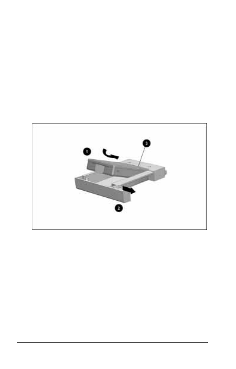
Armada 7000 Removable Drive MultiBay Adapter
The Armada 7000 Removable Drive MultiBay Adapter is
available in two models. To insert or remove a drive from
this adapter:
First, determine whether you have a model with one release
■
latch or two release latches.
The one-latch model 1 has one release latch 2 on the
❏
right side.
The two-latch model 3 has two release latches 4 on
❏
the bottom.
Second, refer to the insertion or removal instructions on the
■
following pages for the model you are using.
Identifying the One-Latch and Two-Latch Models of the Armada 7000 Removable Drive
MultiBay Adapter
Using Removable Drives 7-7
Page 67

To insert a drive into an Armada 7000 Removable Drive
MultiBay Adapter with one release latch
1. Hold the drive with the connector 1 on the right facing the
front 2 of the adapter.
2. Slide the drive into the adapter 3 until the front of the drive is
flush with the front of the adapter.
Inserting a Drive into an Armada 7000 Removable Drive MultiBay Adapter with One
Release Latch
7-8 Using Removable Drives
Page 68

To remove a drive from an Armada 7000 MultiBay Adapter with
one release latch
1. Apply light pressure to both the top and bottom of the release
latch on the right side of the adapter and pull it out slightly 1.
2. Push forward on the back of the drive 2 (without touching the
connector) until you can grasp the front of the drive.
3. Slide the drive out of the adapter 3.
Removing a Drive from an Armada 7000 Removable Drive MultiBay Adapter with One
Release Latch
Using Removable Drives 7-9
Page 69

To insert a drive into an Armada 7000 Removable Drive
MultiBay Adapter with two release latches
1. Slide the two release latches on the bottom of the adapter away
from the center of the adapter until they click into the
unlocked position 1.
2. Hold the drive with the connector on the right side facing the
front of the adapter.
3. Slide the drive into the adapter until the front of the drive 2 is
flush with the front of the adapter.
4. Slide the two release latches toward the center of the adapter
until they click into the locked position 3.
Inserting a Drive into an Armada 7000 Removable Drive MultiBay Adapter with Two
Release Latches
7-10 Using Removable Drives
Page 70

To remove a drive from an Armada 7000 Removable Drive
MultiBay Adapter with two release latches
1. Slide the two release latches on the bottom of the adapter away
from the center of the adapter until they click into the
unlocked position 1.
2. Push forward on the back of the drive 2 (without touching the
connector) until you can grasp the front of the drive.
3. Slide the drive out of the adapter 3.
4. Slide the two release latches toward the center of the adapter
until they click into the locked position 4.
Removing a Drive from an Armada 7000 Removable Drive MultiBay Adapter with Two
Release Latches
Using Removable Drives 7-11
Page 71
LTE 5000 MultiBay Hard Drive Carrier
To insert a drive into an LTE 5000 MultiBay Hard Drive
Carrier
1. If the drive 1 is in a packing or storage tray, remove it from
the tray and from any other packing materials.
2. Make sure the latch 2 inside the carrier is pushed to the right.
3. Place the hard drive into the carrier with the contacts 3 facing
the back of the carrier.
4. Slide the drive to the back of the carrier until it is seated.
5. Push the latch inside the carrier to the left to secure the hard
drive in the carrier.
Inserting a Drive into an LTE 5000 MultiBay Hard Drive Carrier
To remove a drive from an LTE 5000 MultiBay Hard Drive
Carrier
1. Push the latch inside the carrier to the right to release the drive
from the carrier.
2. Pull the drive toward the front of the carrier as you lift it out of
the carrier.
7-12 Using Removable Drives
Page 72
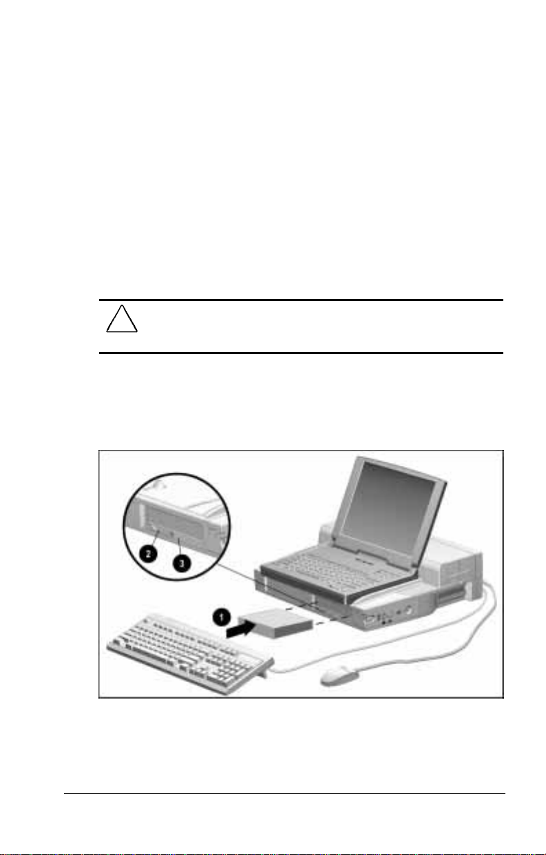
Inserting a Drive or Drive Assembly
into a MultiBay
To insert a drive or drive assembly (a drive inserted into a drive
adapter) into a desktop expansion base MultiBay, follow
these steps:
1. Unlock the expansion base keylock.
2. If you are inserting a diskette drive or a CD-ROM drive,
ensure that no diskettes or CDs are in the drive and that the
CD-ROM drive tray is closed.
3. If you are inserting a drive inserted into an Armada 7000
Removable Drive MultiBay Adapter, make sure the latch or
latches are in the locked (closed) position.
CAUTION:
(open) position into a MultiBay can damage the adapter and make it
difficult to remove from the MultiBay.
4. If the computer is docked, turn off the computer.
5. Slide the drive or drive assembly into the MultiBay 1. When
the drive or drive assembly is seated, the MultiBay device
release latch 2 slides to the right.
Inserting a Drive Assembly into a Desktop Expansion Base MultiBay
Inserting a drive assembly with a latch in the unlocked
The MultiBay light 3 is on while a drive in a MultiBay is
NOTE:
being accessed.
Using Removable Drives 7-13
Page 73

Removing a Drive or Drive Assembly
from a MultiBay
To remove a drive or drive assembly (a drive inserted into a drive
adapter) from a desktop expansion base MultiBay, follow
these steps:
1. Save and close all files and applications on the drive you
are removing.
2. Unlock the expansion base keylock.
3. If you are removing a diskette drive or a CD-ROM drive,
ensure that no diskettes or CDs are in the drive and that the
CD-ROM drive tray is closed.
4. If the computer is docked, turn off the computer.
5. Slide the MultiBay release latch 1 to the left to release the
drive or drive assembly from the MultiBay.
6. Slide the drive or drive assembly out of the MultiBay 2.
Removing a Drive Assembly from a Desktop Expansion Base MultiBay
7-14 Using Removable Drives
Page 74

chapter
8
I
NSERTING AND REMOVING
PC C
ARDS
Adding a PC Card to the System
The desktop expansion base supports any PC Card that is
supported by the computer. Refer to your computer
documentation for information about
Selecting a PC Card that is compatible with your system.
■
Installing card and socket services or enablers.
■
Configuring a PC Card.
■
Responding to prompts or beeps that may occur as you install
■
or remove a PC Card.
Turning off the system before adding or removing a PC Card.
■
Restarting the computer after a PC Card has been added
■
or removed.
CAUTION:
provided by a PC Card manufacturer, you may not be able to use
other PC Cards.
If you install card and socket services or enablers
Inserting and Removing PC Cards 8-1
Page 75

Selecting a PC Card Slot
PC Cards are classified as Type I, Type II, and Type III. The
three types are about the same length and width, but vary in
thickness. Type III cards are the thickest, at less than
one-half inch (10.5 mm).
The desktop expansion base has two PC Card slots. These slots
are
identical.
not
Type I and Type II PC Cards are supported in the top and
■
bottom PC Card slots singly or in any combination.
A Compaq telephony card is supported only in the
■
A Type III or Zoomed Video PC Card is supported only in the
■
PC Card slot. No other PC Card can be used in the top
bottom
slot when a Type III PC Card occupies the bottom slot.
Inserting a PC Card
To insert a PC Card into the expansion base, follow these steps:
1. Unlock the expansion base keylock.
2. Turn off the system.
For information about removing a PC Card without
NOTE:
turning off the system, refer to your computer and PC Card
documentation.
3. Open the PC Card door
it upward 2 from the bottom.
1 on the expansion base by swinging
top
slot.
Opening the PC Card Door
8-2 Inserting and Removing PC Cards
Page 76
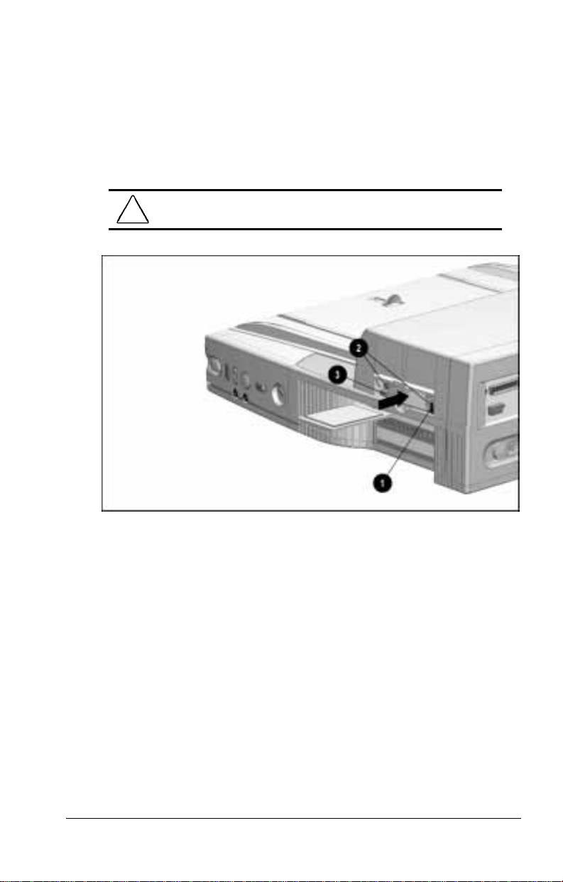
4. If the PC Card security post 1 is blocking access to the PC
Card slot, slide it to the right.
5. Align the PC Card with the horizontal alignment rails 2 on
both sides of the PC Card slot. The 68-pin connector on the
PC Card should be facing the expansion base.
6. Gently push the PC Card into the slot until the PC Card eject
button 3 is flush with the face of the card.
CAUTION:
the connectors.
Inserting a PC Card into the Desktop Expansion Base
Forcing a PC Card into a slot can damage
7. If the PC Card does not have an extension or require cabling,
push down on the base of the PC Card door to close it.
8. If the PC Card requires cabling, refer to the PC Card
documentation for connection information.
9. Restart the system, if appropriate.
Inserting and Removing PC Cards 8-3
Page 77
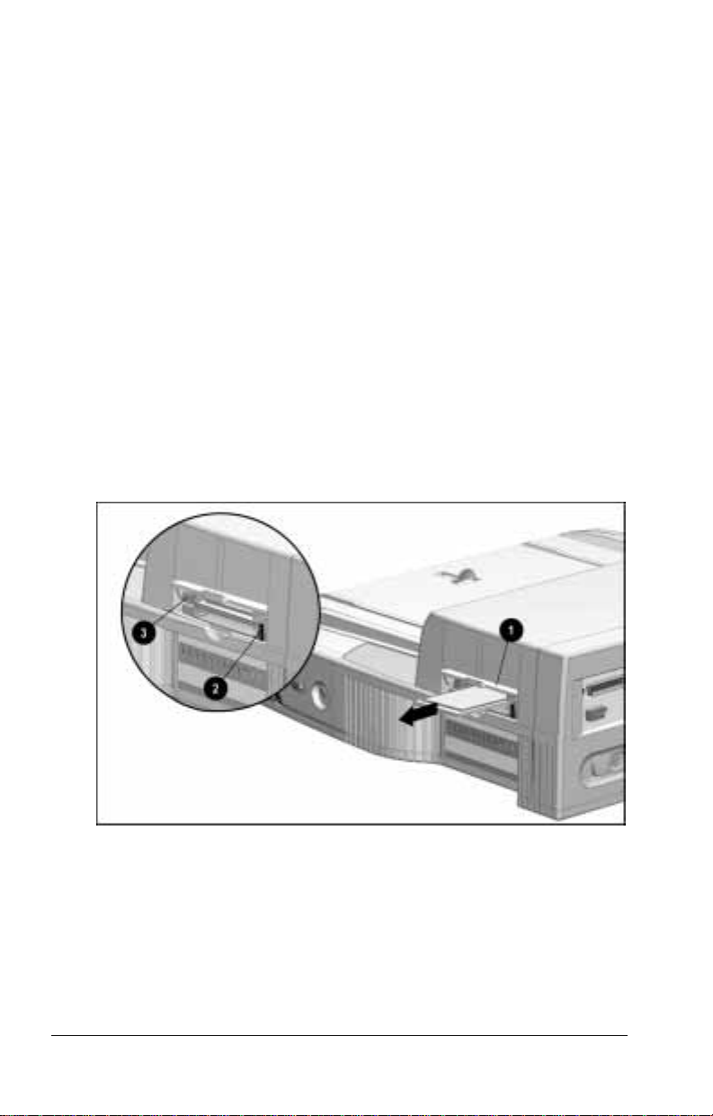
Removing a PC Card
To remove a PC Card from the desktop expansion base, follow
these steps:
1. Unlock the expansion base keylock.
2. Turn off the system.
For information about removing a PC Card without
NOTE:
turning off the system, refer to your computer and
PC Card documentation.
3. If the PC Card door 1 is closed, open it by swinging it upward
from the bottom.
4. Slide the PC Card security post 2 to the right.
5. Press the PC Card eject button 3.
6. Pull the PC Card out of the PC Card slot.
7. Push down on the base of the PC Card door to close it.
8. Restart the system, if appropriate.
Removing a PC Card from the Desktop Expansion Base
8-4 Inserting and Removing PC Cards
Page 78

chapter
9
I
NSTALLING AND REMOVING AN
E
XPANSION BOARD
Installing an Expansion Board
CAUTION:
computer in the Armada 7800 Family of Personal Computers,
installing an optional video card in the expansion base can disable
the Advanced Graphics Port functionality of the system.
Use the following procedure to install a 32-bit PCI expansion
board or a 16-bit or 8-bit full-length ISA expansion board.
Any expansion board can be placed in any available expansion
■
board slot.
Any two expansion boards can be installed at the same time.
■
If you are installing an expansion board, such as a SCSI controller,
that requires a cable connection to a half-height
bay, refer to the expansion board documentation for
connection information.
A SCSI device can be used externally by connecting it to the
NOTE:
external connector on the SCSI controller. For information, refer
to “Accessing Expansion Board Connectors” in this chapter.
If you are using the desktop expansion base with a
Installing and Removing an Expansion Board 9-1
Page 79

Before You Begin
Before you begin, undock the computer and disconnect external
equipment by following these steps:
1. Remove the external monitor and monitor support cover,
if applicable.
2. Save all files and applications, then turn off the computer.
3. Unlock the desktop expansion base keylock.
4. Undock the computer.
5. Turn off all external devices connected to the expansion base.
6. Disconnect all external cables and the power cord from the
expansion base.
Use a Torx T-15 screwdriver.
NOTE:
9-2 Installing and Removing an Expansion Board
Page 80

Removing the Rear Panel
To remove the rear panel, follow these steps:
1. Position the expansion base with the rear panel facing you.
2. Move the rear panel release latch left to the open position.
Releasing the Rear Panel with the Rear Panel Release Latch
3. Using both hands, grasp the bottom sides of the rear panel and
swing the bottom out and up until it disengages.
Removing the Rear Panel
4. When you feel the rear panel detach from the top cover of the
expansion base, lift it up and away from the expansion base.
Installing and Removing an Expansion Board 9-3
Page 81

Removing the Expansion Slot Cover
WARNING:
!
allow the internal system components to cool before touching them.
CAUTION:
components. Before beginning this procedure, ensure that you are
properly grounded. Refer to Appendix C, “Electrostatic Discharge.”
To reduce the risk of personal injury from hot surfaces,
Electrostatic discharge (ESD) can damage electronic
To remove the expansion slot cover, follow these steps:
1. Find the two expansion slot covers
1 and 2 on the right side
of the expansion base. You can install a PCI expansion board
or an ISA expansion board in either the top or the bottom slot.
Select the slot you want to use.
Identifying the Expansion Slot Covers
9-4 Installing and Removing an Expansion Board
Page 82

2. Remove the screw that secures the expansion slot cover to the
expansion slot chassis. This screw will be used later to secure
the newly installed expansion board.
3. Remove the expansion slot cover.
Retain the expansion slot cover. You will need it if you
NOTE:
ever remove the expansion board from the expansion base.
Removing an Expansion Slot Cover
Installing and Removing an Expansion Board 9-5
Page 83

Inserting the Expansion Board
To insert the expansion board onto the input/output (I/O)
assembly, follow these steps:
1. There are four expansion board connectors.
If you have removed the top slot cover, you can insert the
■
expansion board into one of the two top expansion board
slot connectors 1 and 2.
If you have removed the bottom slot cover, you can insert
■
the expansion board into one of the two bottom expansion
board slot connectors 3 and 4.
Select the connector within a slot that matches the
■
connectors on the expansion board. For example, insert a
PCI expansion board into slot connector 1 or 3; insert
an ISA expansion board into slot connector 2 or 4.
Identifying the Expansion Board Connectors
: The top expansion board slot comprises two connectors,
NOTE
and 2. The bottom slot comprises connectors 3 and 4. Only one
expansion board can be installed per slot. If you are installing an
expansion board in the top slot, use connector 1 or 2. If you are
installing an expansion board in the bottom slot, use connector
.
or 4
9-6 Installing and Removing an Expansion Board
1
3
Page 84
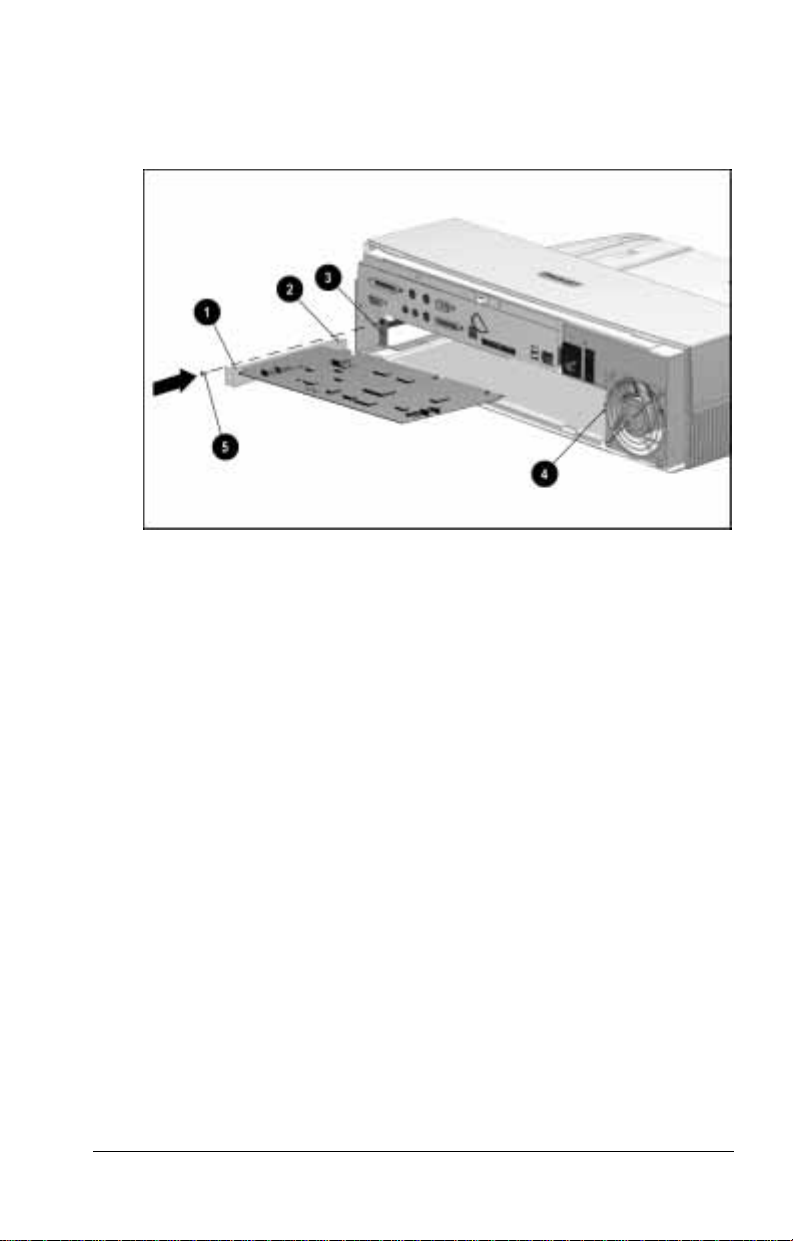
2. Align the bracket 1 on the left side of the expansion board
with the tabs 2 on the slot cover. If you are installing a fulllength expansion board, align the edge of the board opposite
the slot cover chassis 3 with the appropriate alignment rail 4.
Aligning an Expansion Board Bracket with the Tabs on an Expansion Slot Cover Chassis
3. Push the expansion board straight into the expansion board
slot until it is seated.
4. Fasten the expansion board bracket to the expansion board
chassis with the screw 5 that you removed from the expansion
board slot cover.
Installing and Removing an Expansion Board 9-7
Page 85
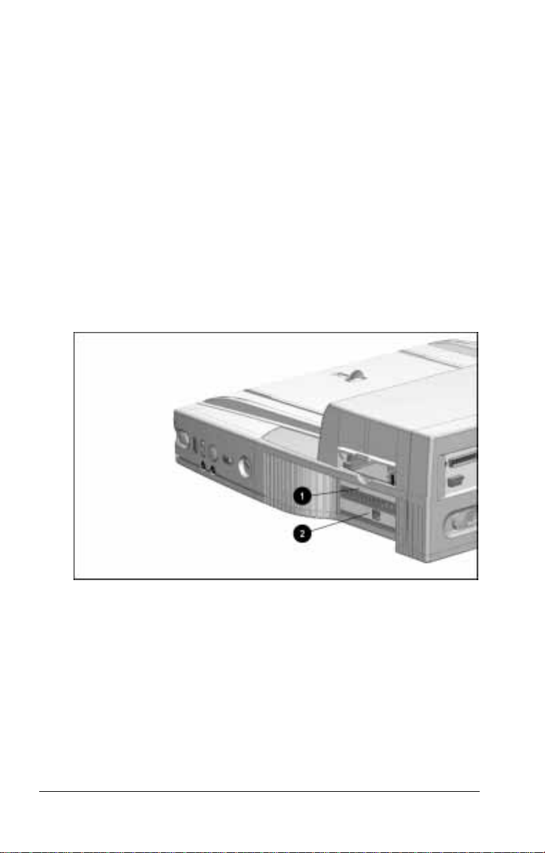
Replacing the Rear Panel
To replace the rear panel, follow these steps:
1. Replace the rear panel by inserting the tabs on the top of the
rear panel into the slots in the top cover. When the tabs are in
the slots, pivot the bottom of the rear panel downward until it
is seated.
2. Secure the rear panel by moving the rear panel release latch
right to the closed position.
3. Reconnect the power cord and all external equipment cables to
the expansion base.
Accessing Expansion Board Connectors
Once an expansion board is installed in the top 1 or bottom
2
slot, you can access its connectors from the right side of the
expansion base.
Accessing an Expansion Board Connector
If the expansion board that has been installed has a cable, refer to
the documentation included with the expansion board for
connection information.
9-8 Installing and Removing an Expansion Board
Page 86

Removing an Expansion Board
Use the following procedure to remove a 32-bit PCI expansion
board or a 16-bit or 8-bit full-length ISA expansion board.
Use a Torx T-15 screwdriver.
NOTE:
1. Disconnect any exterior cables connected to the expansion
board that you plan to remove.
2. Follow the procedures under “Before You Begin” and
“Removing the Rear Panel” in “Installing an Expansion
Board” in this chapter.
3. Remove the screw 1 that is securing the expansion board to
the chassis 2. This screw will be used later:
If you replace the expansion board that you are removing,
■
you will use the screw to secure the new expansion board.
If you do not replace the expansion board that you are
■
removing, you will use the screw to secure an expansion
slot cover.
Removing an Expansion Board
4. Pull the expansion board straight out.
Installing and Removing an Expansion Board 9-9
Page 87

5. If you are not installing another expansion board in the same
expansion slot, replace the expansion board slot cover. (This is
the slot cover that was removed when the expansion board was
installed.) Attach it to the expansion slot cover chassis with
the screw that you removed in step 3.
If you are inserting a different expansion board into the same
expansion slot, refer to “Installing an Expansion Board”
earlier in this chapter and follow the instructions in these
sections:
First, “Inserting the Expansion Board onto the
■
I/O Assembly”
Second, “Replacing the Rear Panel”
■
Third, “Accessing Expansion Board Connectors”
■
Replacing an Expansion Slot Cover
6. Replace the rear panel by inserting the tabs on the top of the
rear panel into the slots in the top cover. When the tabs are in
the slots, pivot the bottom of the rear panel downward until it
is seated.
7. Secure the rear panel by moving the rear panel release latch
right to the closed position.
8. Reconnect the power cord and all external equipment cables to
the expansion base.
9-10 Installing and Removing an Expansion Board
Page 88

chapter
10
I
NSTALLING AND REMOVING A
H
ALF
Installing a Half-Height Bay Device
-H
EIGHT BAY DEVICE
This procedure explains how to install a standard half-height drive
in a half-height bay. A half-height drive power cable is
preinstalled inside the desktop expansion base.
The procedures for installing an Armada 7000 Half-Height
MultiBay Adapter or an LTE 5000 Half-Height MultiBay
Adapter are similar. Refer to the adapter documentation for
specific instructions.
Use slotted Torx T-10 and T-15 screwdrivers.
NOTE:
Installing and Removing a Half-Height Bay Device 10-1
Page 89

Caring for Half-Height Drives
Half-height drives are fragile components that must be handled
with care.
CAUTION:
To prevent damage to the computer, damage to a
removable drive, or loss of information, observe these precautions:
Before removing or inserting a hard drive, shut down the
■
computer. If you are unsure whether the computer is off or in
Hibernation, turn the computer on, then shut it down.
Before removing a diskette drive, ensure that a diskette is
■
not
the drive.
Before removing a CD-ROM drive, ensure that a compact disc is
■
in the drive and that the CD-ROM tray is closed.
not
Before handling a drive, ensure that you are discharged of static
■
electricity. While handling a drive, avoid touching the connector.
For more information about preventing electrostatic damage,
refer to Appendix C.
Handle a drive carefully; do not drop it.
■
Avoid exposing a hard drive to products that have magnetic fields
■
such as monitors or speakers.
Avoid exposing a drive to temperature extremes.
■
Avoid exposing a drive to liquids. Do not spray it with cleaners.
■
Do not use excessive force when inserting a drive into a
■
drive bay.
If a drive must be mailed, do the following. Place the drive into a
■
into a bubble pack mailer or other suitable form of protective
packaging. Label the package “Fragile: Handle With Care.”
in
10-2 Installing and Removing a Half-Height Bay Device
Page 90

Before You Begin
Before you begin, undock the computer and disconnect external
equipment by following these steps:
1. Save all files and applications, then turn off the computer.
2. Remove the external monitor and monitor support cover, if
in place.
3. Unlock the desktop expansion base keylock.
4. Undock the computer.
5. Turn off all external devices connected to the expansion base.
6. Disconnect all external cables and the power cord from the
expansion base.
Installing and Removing a Half-Height Bay Device 10-3
Page 91

Removing the Rear Panel
To remove the rear panel, follow these steps:
1. Position the expansion base with the rear panel facing you.
2. Slide the rear panel release latch left to the open position.
Sliding the Rear Panel Release Latch to Release the Rear Panel
3. Using both hands, grasp the bottom sides of the rear panel and
swing the bottom out and up until it disengages.
Removing the Rear Panel
4. When you feel the rear panel detach from the top cover of the
expansion base, lift it up and away from the expansion base.
10-4 Installing and Removing a Half-Height Bay Device
Page 92
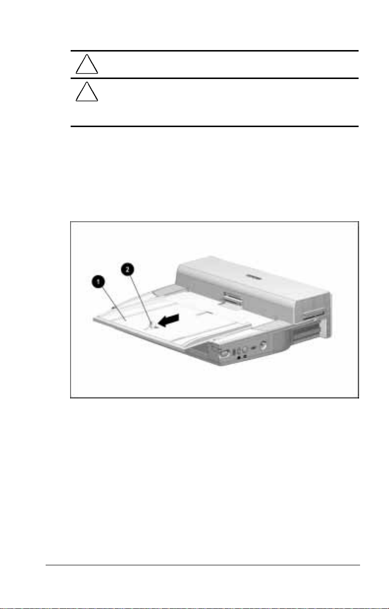
Removing the Top Cover
WARNING:
!
allow the internal system components to cool before touching them.
CAUTION:
components. Before beginning this procedure, ensure that you are
properly grounded. For more information, refer to Appendix C,
“Electrostatic Discharge.”
To reduce the risk of personal injury from hot surfaces,
Electrostatic discharge (ESD) can damage electronic
To remove the top cover, follow these steps:
1. Reposition the expansion base so that the front of the
expansion base is facing you.
2. Remove the alignment tray
1 from the expansion base by
pulling the docking latch 2 forward.
Removing the Alignment Tray from the Desktop Expansion Base
Installing and Removing a Half-Height Bay Device 10-5
Page 93
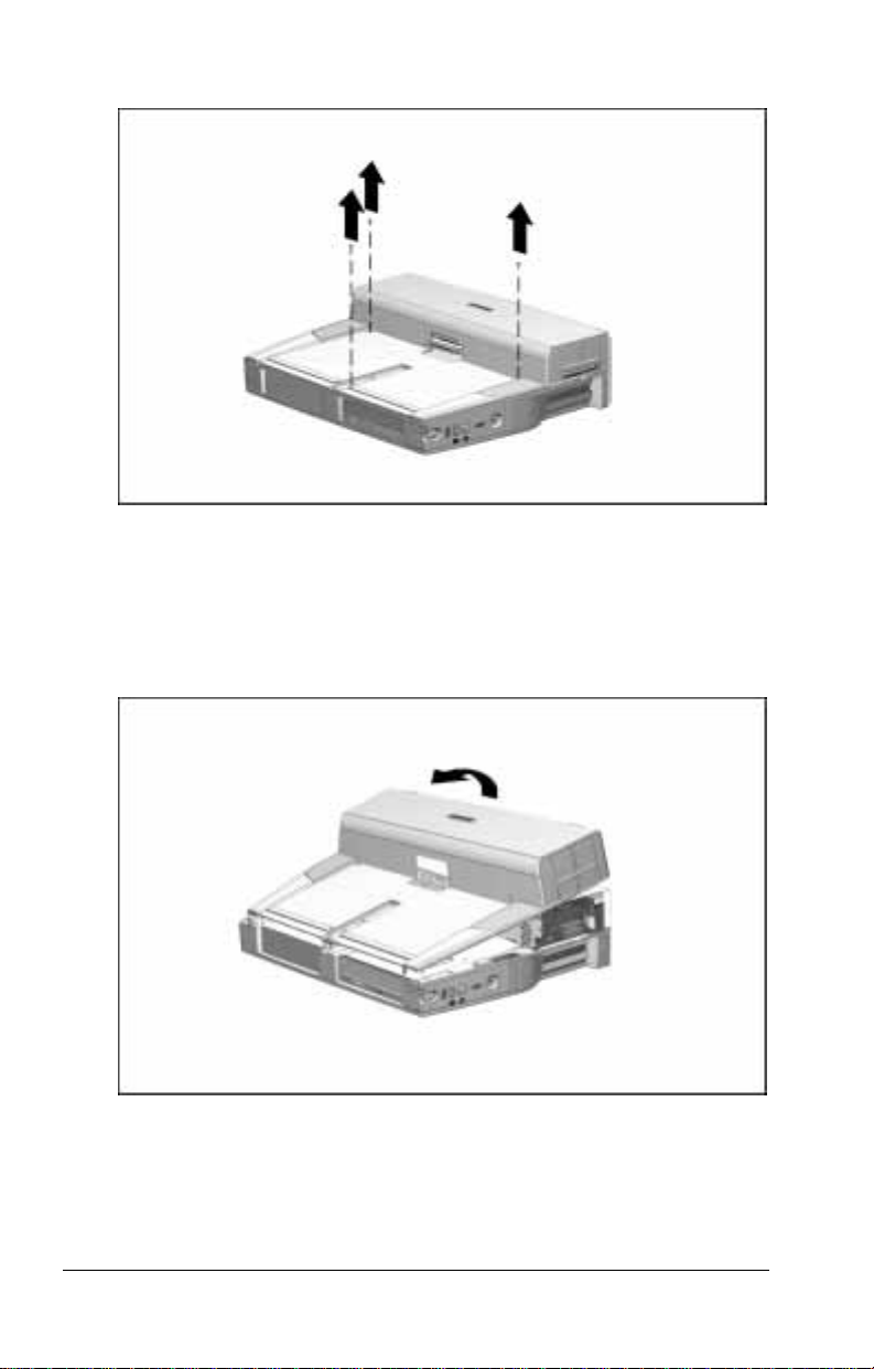
3. Remove and retain the three screws from the top cover.
Removing the Screws from the Top Cover
4. Using both hands, grasp the top outside edges of the
top cover.
5. Lift the back edge of the top cover and swing it forward. The
top cover pivots off the expansion base along the front edge.
Removing the Top Cover
10-6 Installing and Removing a Half-Height Bay Device
Page 94

Removing the Drive Cage
To remove the drive cage, follow these steps:
1. Remove and retain the three screws securing the metal drive
cage shield to the expansion base. The screws are two sizes.
Removing the Screws from the Drive Cage Shield
2. Lift the front edge of the metal drive cage shield and swing it
approximately 45 degrees upward. Then pull it toward you.
The shield pivots along the four tabs extending into the metal
plate at the rear of the drive cage shield.
Removing the Drive Cage Shield from the Desktop Expansion Base
Installing and Removing a Half-Height Bay Device 10-7
Page 95

3. Lift the drive cage out of the expansion base.
Removing the Drive Cage from the Desktop Expansion Base
Inserting the Half-Height Drive into the Drive Cage
To insert the drive into the drive cage, follow these steps:
1. Remove the half-height bay blank bezel by pressing lightly in
its center as you pull its edges away from the drive cage.
Retain this bezel. You will need it if you ever remove
NOTE:
and do not replace the half-height drive that you are installing.
Removing the Half-Height Bay Blank Bezel from the Drive Cage
10-8 Installing and Removing a Half-Height Bay Device
Page 96

2. Remove the four screws from the drive.
Removing the Screws from the Half-Height Drive
3. Place the drive cage over the half-height drive.
4. Attach the drive cage to the half-height drive by loosely
replacing the four screws that you removed from the halfheight drive. Insert the screws through the drive cage and into
the half-height drive.
Two sets of screw holes are provided on each side of the
NOTE:
drive cage. Select the pairs of holes that match the holes in the
sides of the half-height drive.
Attaching the Drive Cage to the Half-Height Drive
Installing and Removing a Half-Height Bay Device 10-9
Page 97

5. Align the front cover of the half-height drive with the front
edge of the tab on the inside edge of the drive cage.
Aligning the Half-Height Drive with the Drive Cage
6. Tighten the four screws that secure the drive cage to the halfheight drive.
10-10 Installing and Removing a Half-Height Bay Device
Page 98

Inserting the Drive Cage Assembly into the Desktop
Expansion Base
To insert the drive cage assembly (the drive cage attached to the
half-height drive) into the expansion base, follow these steps:
1. Attach the cables on the back of the half-height drive to the
connectors on the expansion base. For connection information,
refer to the half-height drive documentation.
2. Align the holes in the front and rear base tabs of the drive cage
with the pins on the bottom of the expansion base.
3. Place the aligned drive cage assembly on the bottom of the
expansion base.
Placing the Drive Cage Assembly onto the Bottom of the Desktop Expansion Base
Installing and Removing a Half-Height Bay Device 10-11
Page 99
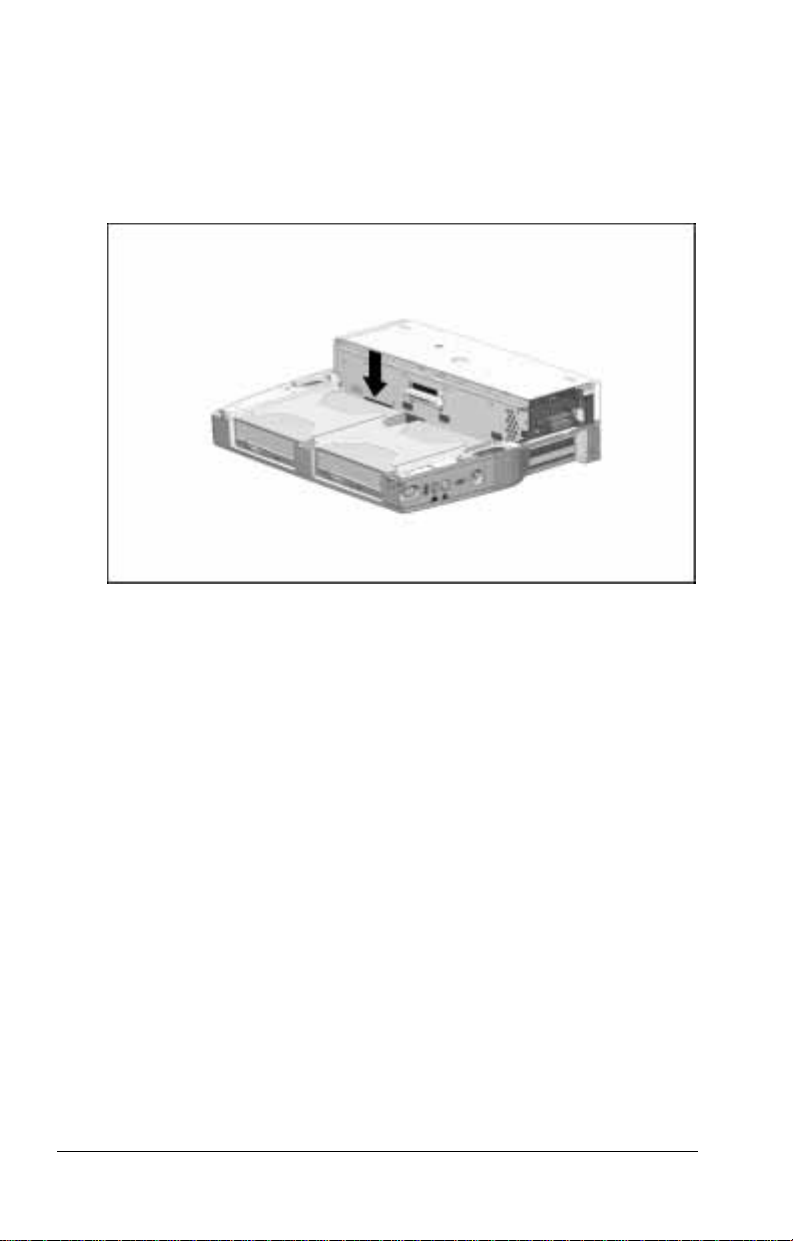
4. Connect the half-height drive power cable included with the
expansion base and any other cables required by the drive as
directed in the documentation that came with the drive.
5. Tuck the cables attaching the drive cage assembly to the
expansion base beneath the slots that will be used to reconnect
the metal drive cage shield to the metal plate
Tucking Cables Beneath the Drive Cage Shield Slots
6. Replace the drive cage shield by inserting the four tabs along
the back of the drive cage shield into the four slots on the
metal plate. (Be sure no cables are caught between the drive
cage shield and the metal plate.)
10-12 Installing and Removing a Half-Height Bay Device
Page 100

7. Replace the three screws that secure the drive cage. The two
matching screws go into the outside rails. Ensure that the right
screw 1 secures the grounding strap grommet 2 to the drive
cage shield.
Replacing the Screws in the Drive Cage Shield
Installing and Removing a Half-Height Bay Device 10-13
 Loading...