

Page 1

installation
guide
hp StorageWorks
core switch 2/64
Product Version: 4.1.x
Third Edition (June 2003)
Part Number: AA-RS2WC-TE
This installation guide provides procedures for setting up, configuring, and managing the
Core Switch 2/64 and Core Switch 2/64 power pak.
For the most current information about the HP StorageWorks Core Switch 2/64, visit the
support Web site located at
http://www.hp.com/products1/storage/products/san/fibreswitches/coreswitch2_64/index.html
.
Page 2

Copyright 1999-2003 Hewlett-Packard Development Company, L.P.
Hewlett-Packard Company makes no warranty of any kind with regard to this material, including, but not limited
to, the implied warranties of merchantability and fitness for a particular purpose. Hewlett-Packard shall not be
liable for errors contained herein or for incidental or consequential damages in connection with the furnishing,
performance, or use of this material.
This document contains proprietary information, which is protected by copyright. No part of this document may be
photocopied, reproduced, or translated into another language without the prior written consent of Hewlett-Packard.
The information contained in this document is subject to change without notice.
BROCADE, the Brocade B weave logo, Brocade: the Intelligent Platform for Networking Storage, SilkWorm, and
SilkWork Express, are trademarks or registered trademarks of Brocade Communications Systems, Inc. or its
subsidiaries in the United States and/or in other countries.
Hewlett-Packard Company shall not be liable for technical or editorial errors or omissions contained herein. The
information is provided “as is” without warranty of any kind and is subject to change without notice. The warranties
for Hewlett-Packard Company products are set forth in the express limited warranty statements for such products.
Nothing herein should be construed as constituting an additional warranty.
Printed in the U.S.A.
Core Switch 2/64 V4.1 Installation Guide
Third Edition (June 2003)
Part Number: AA-RS2WC-TE
Page 3

contents
Intended Audience . . . . . . . . . . . . . . . . . . . . . . . . . . . . . . . . . . . . . . . . . . . . . . . . . . . . . . . . . 13
Related Documentation . . . . . . . . . . . . . . . . . . . . . . . . . . . . . . . . . . . . . . . . . . . . . . . . . . . . . 13
Conventions . . . . . . . . . . . . . . . . . . . . . . . . . . . . . . . . . . . . . . . . . . . . . . . . . . . . . . . . . . . . . . 14
Document Conventions . . . . . . . . . . . . . . . . . . . . . . . . . . . . . . . . . . . . . . . . . . . . . . . . . . 14
Text Symbols . . . . . . . . . . . . . . . . . . . . . . . . . . . . . . . . . . . . . . . . . . . . . . . . . . . . . . . . . . 15
Equipment Symbols . . . . . . . . . . . . . . . . . . . . . . . . . . . . . . . . . . . . . . . . . . . . . . . . . . . . . 15
Rack Stability . . . . . . . . . . . . . . . . . . . . . . . . . . . . . . . . . . . . . . . . . . . . . . . . . . . . . . . . . . . . . 16
Getting Help . . . . . . . . . . . . . . . . . . . . . . . . . . . . . . . . . . . . . . . . . . . . . . . . . . . . . . . . . . . . . . 17
HP Technical Support . . . . . . . . . . . . . . . . . . . . . . . . . . . . . . . . . . . . . . . . . . . . . . . . . . . 17
HP Storage Website . . . . . . . . . . . . . . . . . . . . . . . . . . . . . . . . . . . . . . . . . . . . . . . . . . . . . 17
HP Authorized Reseller . . . . . . . . . . . . . . . . . . . . . . . . . . . . . . . . . . . . . . . . . . . . . . . . . . 18
1 Overview . . . . . . . . . . . . . . . . . . . . . . . . . . . . . . . . . . . . . . . . . . . . . . . . . . . . . . . .19
High Availability . . . . . . . . . . . . . . . . . . . . . . . . . . . . . . . . . . . . . . . . . . . . . . . . . . . . . . . . . . 20
Firmware Version 4.0 Summary . . . . . . . . . . . . . . . . . . . . . . . . . . . . . . . . . . . . . . . . . . . 20
Port Side of Chassis . . . . . . . . . . . . . . . . . . . . . . . . . . . . . . . . . . . . . . . . . . . . . . . . . . . . . 21
Core Switch 2/64 Fibre Channel Ports . . . . . . . . . . . . . . . . . . . . . . . . . . . . . . . . 24
Blower Assembly Side of Chassis . . . . . . . . . . . . . . . . . . . . . . . . . . . . . . . . . . . . . . . . . . 24
Cabling Summary. . . . . . . . . . . . . . . . . . . . . . . . . . . . . . . . . . . . . . . . . . . . . . . . . . . . . . . . . . 27
Fibre Optic Cable Requirements . . . . . . . . . . . . . . . . . . . . . . . . . . . . . . . . . . . . . . . . . . . 27
Managing Cables . . . . . . . . . . . . . . . . . . . . . . . . . . . . . . . . . . . . . . . . . . . . . . . . . . . . . . . 27
Cable Management Tray and Cable Guides. . . . . . . . . . . . . . . . . . . . . . . . . . . . . . . . . . . 28
Cabling Precautions . . . . . . . . . . . . . . . . . . . . . . . . . . . . . . . . . . . . . . . . . . . . . . . . . . . . . 28
Management Summary. . . . . . . . . . . . . . . . . . . . . . . . . . . . . . . . . . . . . . . . . . . . . . . . . . . . . . 29
Optional Management Features . . . . . . . . . . . . . . . . . . . . . . . . . . . . . . . . . . . . . . . . . . . . 29
Optional Hardware Kits . . . . . . . . . . . . . . . . . . . . . . . . . . . . . . . . . . . . . . . . . . . . . . . . . . . . . 30
Managing and Monitoring the Core Switch 2/64 . . . . . . . . . . . . . . . . . . . . . . . . . . . . . . . . . . 31
3Core Switch 2/64 V4.1 Installation Guide
Page 4

Contents
Managing the Core Switch 2/64. . . . . . . . . . . . . . . . . . . . . . . . . . . . . . . . . . . . . . . . . . . . 31
Supported Features. . . . . . . . . . . . . . . . . . . . . . . . . . . . . . . . . . . . . . . . . . . . . . . . . . . . . . 32
2 Installing and Configuring the
Core Switch 2/64 . . . . . . . . . . . . . . . . . . . . . . . . . . . . . . . . . . . . . . . . . . . . . . . . . .35
Installation and Safety Considerations . . . . . . . . . . . . . . . . . . . . . . . . . . . . . . . . . . . . . . . . . . 37
Unpack and Verify Carton Contents. . . . . . . . . . . . . . . . . . . . . . . . . . . . . . . . . . . . . . . . . . . . 39
Installation Overview . . . . . . . . . . . . . . . . . . . . . . . . . . . . . . . . . . . . . . . . . . . . . . . . . . . . . . . 43
Selecting an Operating Location . . . . . . . . . . . . . . . . . . . . . . . . . . . . . . . . . . . . . . . . . . . 43
Cooling Requirements. . . . . . . . . . . . . . . . . . . . . . . . . . . . . . . . . . . . . . . . . . . . . . . . 43
Power Requirements . . . . . . . . . . . . . . . . . . . . . . . . . . . . . . . . . . . . . . . . . . . . . . . . . 44
Installing the Switch as a Stand-alone Unit . . . . . . . . . . . . . . . . . . . . . . . . . . . . . . . . . . . 44
Removing the Chassis Door . . . . . . . . . . . . . . . . . . . . . . . . . . . . . . . . . . . . . . . . . . . 45
Installing the Core Switch 2/64 on a Flat Surface. . . . . . . . . . . . . . . . . . . . . . . . . . . 46
Installing the Core Switch 2/64 in a Rack . . . . . . . . . . . . . . . . . . . . . . . . . . . . . . . . . . . . 47
Pre-installation Checklist. . . . . . . . . . . . . . . . . . . . . . . . . . . . . . . . . . . . . . . . . . . . . . . . . 47
Items Required for Installation. . . . . . . . . . . . . . . . . . . . . . . . . . . . . . . . . . . . . . . . . . . . . 47
Important Rack Mount Guidelines. . . . . . . . . . . . . . . . . . . . . . . . . . . . . . . . . . . . . . . . . . 48
Installing the Core Switch 2/64 in a 9000 Series, 42U Rack. . . . . . . . . . . . . . . . . . . . . . 50
Attaching the Rack Mount Shelf Brackets . . . . . . . . . . . . . . . . . . . . . . . . . . . . . . . . 50
For Rails with Square Holes—Attaching the Retainer Nuts. . . . . . . . . . . . . . . . . . . 53
For Rails with Round Holes—Attaching the Clip Nuts . . . . . . . . . . . . . . . . . . . . . . 54
Attaching the Upper Rack Mount Bracket Assemblies to the Chassis . . . . . . . . . . . 54
Finalizing the Rack Mount Procedure. . . . . . . . . . . . . . . . . . . . . . . . . . . . . . . . . . . . 58
Sliding the Switch into the Rack. . . . . . . . . . . . . . . . . . . . . . . . . . . . . . . . . . . . . 58
Securing the Chassis to the Rails . . . . . . . . . . . . . . . . . . . . . . . . . . . . . . . . . . . . 58
Reinstalling the Chassis Door. . . . . . . . . . . . . . . . . . . . . . . . . . . . . . . . . . . . . . . 60
Installing the Switch in the Optional HP System/e Rack. . . . . . . . . . . . . . . . . . . . . . . . . 61
Powering On for the First Time . . . . . . . . . . . . . . . . . . . . . . . . . . . . . . . . . . . . . . . . . . . . . . . 67
Installing the Power Cord Retainers . . . . . . . . . . . . . . . . . . . . . . . . . . . . . . . . . . . . . . . . 67
Connecting Power Cords . . . . . . . . . . . . . . . . . . . . . . . . . . . . . . . . . . . . . . . . . . . . . . . . . 68
Running POST . . . . . . . . . . . . . . . . . . . . . . . . . . . . . . . . . . . . . . . . . . . . . . . . . . . . . . . . . 69
Checking POST Results. . . . . . . . . . . . . . . . . . . . . . . . . . . . . . . . . . . . . . . . . . . . . . . . . . 70
Core Switch PID Format Summary . . . . . . . . . . . . . . . . . . . . . . . . . . . . . . . . . . . . . . . . . . . . 71
Important Information on Checking the Core Switch PID Format . . . . . . . . . . . . . . . . . 71
Configuration Overview. . . . . . . . . . . . . . . . . . . . . . . . . . . . . . . . . . . . . . . . . . . . . . . . . . . . . 73
Preset Configuration Settings. . . . . . . . . . . . . . . . . . . . . . . . . . . . . . . . . . . . . . . . . . . . . . 74
Configuring Core Switch 2/64 Network Addressing . . . . . . . . . . . . . . . . . . . . . . . . . . . . . . . 75
Items Required . . . . . . . . . . . . . . . . . . . . . . . . . . . . . . . . . . . . . . . . . . . . . . . . . . . . . . . . . 75
4 Core Switch 2/64 V4.1 Installation Guide
Page 5

Contents
Setting Network Addresses via a Network Connection. . . . . . . . . . . . . . . . . . . . . . . . . . 76
Connecting the Core Switch 2/64 to the LAN . . . . . . . . . . . . . . . . . . . . . . . . . . . . . . . . . 80
Modifying Domain IDs . . . . . . . . . . . . . . . . . . . . . . . . . . . . . . . . . . . . . . . . . . . . . . . . . . 81
Specify Custom Status Policies . . . . . . . . . . . . . . . . . . . . . . . . . . . . . . . . . . . . . . . . . . . . 81
Connecting SFPs . . . . . . . . . . . . . . . . . . . . . . . . . . . . . . . . . . . . . . . . . . . . . . . . . . . . . . . 82
Saving the System Configuration Files . . . . . . . . . . . . . . . . . . . . . . . . . . . . . . . . . . . . . . . . . 85
Backing up the Switch Configuration Settings . . . . . . . . . . . . . . . . . . . . . . . . . . . . . . . . 85
Restoring the System Configuration Settings . . . . . . . . . . . . . . . . . . . . . . . . . . . . . . . . . 86
Setting Up Speed Negotiation . . . . . . . . . . . . . . . . . . . . . . . . . . . . . . . . . . . . . . . . . . . . . . . . 87
3 Operating the Core Switch 2/64 . . . . . . . . . . . . . . . . . . . . . . . . . . . . . . . . . . . . . . .89
Powering the Core Switch 2/64 On and Off. . . . . . . . . . . . . . . . . . . . . . . . . . . . . . . . . . . . . . 90
Operating Information for System Components. . . . . . . . . . . . . . . . . . . . . . . . . . . . . . . . . . . 91
Port Cards. . . . . . . . . . . . . . . . . . . . . . . . . . . . . . . . . . . . . . . . . . . . . . . . . . . . . . . . . . . . . 91
Control Processor Cards. . . . . . . . . . . . . . . . . . . . . . . . . . . . . . . . . . . . . . . . . . . . . . . . . . 92
About the CP Card. . . . . . . . . . . . . . . . . . . . . . . . . . . . . . . . . . . . . . . . . . . . . . . . . . . 92
Available Ports . . . . . . . . . . . . . . . . . . . . . . . . . . . . . . . . . . . . . . . . . . . . . . . . . . . . . 93
Modem Connection . . . . . . . . . . . . . . . . . . . . . . . . . . . . . . . . . . . . . . . . . . . . . . . . . . 93
Services Controlled by the CP Card . . . . . . . . . . . . . . . . . . . . . . . . . . . . . . . . . . . . . 93
Determining the Status of the CP Card . . . . . . . . . . . . . . . . . . . . . . . . . . . . . . . . . . . 94
Power Supplies. . . . . . . . . . . . . . . . . . . . . . . . . . . . . . . . . . . . . . . . . . . . . . . . . . . . . . . . . 94
AC Power Input Connectors and AC Power Switches . . . . . . . . . . . . . . . . . . . . . . . . . . 95
Blower Assemblies. . . . . . . . . . . . . . . . . . . . . . . . . . . . . . . . . . . . . . . . . . . . . . . . . . . . . . 95
WWN Card and Bezel . . . . . . . . . . . . . . . . . . . . . . . . . . . . . . . . . . . . . . . . . . . . . . . . . . . 96
Managing Cables . . . . . . . . . . . . . . . . . . . . . . . . . . . . . . . . . . . . . . . . . . . . . . . . . . . . . . . 98
Reviewing Default Configuration Settings. . . . . . . . . . . . . . . . . . . . . . . . . . . . . . . . . . . . . . . 99
Core Switch 2/64 Switch Settings . . . . . . . . . . . . . . . . . . . . . . . . . . . . . . . . . . . . . . . . . . 99
Default Fabric Parameters . . . . . . . . . . . . . . . . . . . . . . . . . . . . . . . . . . . . . . . . . . . . . . . . 99
Default Virtual Channel Settings . . . . . . . . . . . . . . . . . . . . . . . . . . . . . . . . . . . . . . . . . . 100
Interpreting LED Activity. . . . . . . . . . . . . . . . . . . . . . . . . . . . . . . . . . . . . . . . . . . . . . . . . . . 101
System Components . . . . . . . . . . . . . . . . . . . . . . . . . . . . . . . . . . . . . . . . . . . . . . . . . . . . . . . 102
16-Port Card LEDs. . . . . . . . . . . . . . . . . . . . . . . . . . . . . . . . . . . . . . . . . . . . . . . . . . . . . 102
CP Card LEDs . . . . . . . . . . . . . . . . . . . . . . . . . . . . . . . . . . . . . . . . . . . . . . . . . . . . . . . . 106
Power Supply LEDs. . . . . . . . . . . . . . . . . . . . . . . . . . . . . . . . . . . . . . . . . . . . . . . . . . . . 109
Blower Assemblies LEDs . . . . . . . . . . . . . . . . . . . . . . . . . . . . . . . . . . . . . . . . . . . . . . . 112
WWN Card LEDs . . . . . . . . . . . . . . . . . . . . . . . . . . . . . . . . . . . . . . . . . . . . . . . . . . . . . 114
SFPs . . . . . . . . . . . . . . . . . . . . . . . . . . . . . . . . . . . . . . . . . . . . . . . . . . . . . . . . . . . . . . . . 115
Interpreting POST Results . . . . . . . . . . . . . . . . . . . . . . . . . . . . . . . . . . . . . . . . . . . . . . . . . . 116
Performing Diagnostic Tests . . . . . . . . . . . . . . . . . . . . . . . . . . . . . . . . . . . . . . . . . . . . . . . . 117
5Core Switch 2/64 V4.1 Installation Guide
Page 6

Contents
Environmental Status and Maintenance Commands . . . . . . . . . . . . . . . . . . . . . . . . . . . . . . 118
chassisShow . . . . . . . . . . . . . . . . . . . . . . . . . . . . . . . . . . . . . . . . . . . . . . . . . . . 118
slotShow . . . . . . . . . . . . . . . . . . . . . . . . . . . . . . . . . . . . . . . . . . . . . . . . . . . . . . 119
sensorShow . . . . . . . . . . . . . . . . . . . . . . . . . . . . . . . . . . . . . . . . . . . . . . . . . . . . 119
psShow . . . . . . . . . . . . . . . . . . . . . . . . . . . . . . . . . . . . . . . . . . . . . . . . . . . . . . . 120
fanShow . . . . . . . . . . . . . . . . . . . . . . . . . . . . . . . . . . . . . . . . . . . . . . . . . . . . . . 120
errShow. . . . . . . . . . . . . . . . . . . . . . . . . . . . . . . . . . . . . . . . . . . . . . . . . . . . . . . 120
4 Installing Core Switch 2/64 FRUs. . . . . . . . . . . . . . . . . . . . . . . . . . . . . . . . . . . . . .121
FRU Summary . . . . . . . . . . . . . . . . . . . . . . . . . . . . . . . . . . . . . . . . . . . . . . . . . . . . . . . . . . . 122
Notifying the Switch of a Hot Swap . . . . . . . . . . . . . . . . . . . . . . . . . . . . . . . . . . . . . . . 122
Checking FRU Status. . . . . . . . . . . . . . . . . . . . . . . . . . . . . . . . . . . . . . . . . . . . . . . . . . . 122
Display Switch Status . . . . . . . . . . . . . . . . . . . . . . . . . . . . . . . . . . . . . . . . . . . . . . . 122
Display Slot Status. . . . . . . . . . . . . . . . . . . . . . . . . . . . . . . . . . . . . . . . . . . . . . . . . . 123
Display Component Temperatures . . . . . . . . . . . . . . . . . . . . . . . . . . . . . . . . . . . . . 124
Display Power Supply Status . . . . . . . . . . . . . . . . . . . . . . . . . . . . . . . . . . . . . . . . . 124
Display Blower Assembly Status . . . . . . . . . . . . . . . . . . . . . . . . . . . . . . . . . . . . . . 124
Display Failed Components. . . . . . . . . . . . . . . . . . . . . . . . . . . . . . . . . . . . . . . . . . . 125
16-Port Card or Filler Panel Summary. . . . . . . . . . . . . . . . . . . . . . . . . . . . . . . . . . . . . . . . . 126
16-Port Card Precautionary Guidelines . . . . . . . . . . . . . . . . . . . . . . . . . . . . . . . . . . . . . 126
Time and Items. . . . . . . . . . . . . . . . . . . . . . . . . . . . . . . . . . . . . . . . . . . . . . . . . . . . . . . . 127
Replacing a Filler Panel or 16-port Card . . . . . . . . . . . . . . . . . . . . . . . . . . . . . . . . . . . . 127
Recommendations for Cable Management . . . . . . . . . . . . . . . . . . . . . . . . . . . . . . . 132
CP Card Summary . . . . . . . . . . . . . . . . . . . . . . . . . . . . . . . . . . . . . . . . . . . . . . . . . . . . . . . . 133
Time and Items. . . . . . . . . . . . . . . . . . . . . . . . . . . . . . . . . . . . . . . . . . . . . . . . . . . . . . . . 133
Confirming a Failed CP Card. . . . . . . . . . . . . . . . . . . . . . . . . . . . . . . . . . . . . . . . . . . . . 134
Recording Critical Switch Information . . . . . . . . . . . . . . . . . . . . . . . . . . . . . . . . . . 135
Replacing a Filler Panel or CP Card . . . . . . . . . . . . . . . . . . . . . . . . . . . . . . . . . . . . . . . 139
About the CP Card (or RTC) Battery. . . . . . . . . . . . . . . . . . . . . . . . . . . . . . . . . . . . . . . 142
Verifying Operation of the New CP Card . . . . . . . . . . . . . . . . . . . . . . . . . . . . . . . . . . . 142
Power Supply Summary . . . . . . . . . . . . . . . . . . . . . . . . . . . . . . . . . . . . . . . . . . . . . . . . . . . . 149
Replacing the Power Supply or Filler Panel . . . . . . . . . . . . . . . . . . . . . . . . . . . . . . . . . 149
Blower Assembly Summary. . . . . . . . . . . . . . . . . . . . . . . . . . . . . . . . . . . . . . . . . . . . . . . . . 153
Time and Items. . . . . . . . . . . . . . . . . . . . . . . . . . . . . . . . . . . . . . . . . . . . . . . . . . . . . . . . 153
Replacing the Blower Assembly . . . . . . . . . . . . . . . . . . . . . . . . . . . . . . . . . . . . . . . . . . 153
Replacing SFPs. . . . . . . . . . . . . . . . . . . . . . . . . . . . . . . . . . . . . . . . . . . . . . . . . . . . . . . . . . . 157
Cable Management Tray Summary . . . . . . . . . . . . . . . . . . . . . . . . . . . . . . . . . . . . . . . . . . . 159
Time and Items. . . . . . . . . . . . . . . . . . . . . . . . . . . . . . . . . . . . . . . . . . . . . . . . . . . . . . . . 159
Replacing the Cable Management Tray. . . . . . . . . . . . . . . . . . . . . . . . . . . . . . . . . . . . . 159
6 Core Switch 2/64 V4.1 Installation Guide
Page 7

Contents
Replacing the WWN Card . . . . . . . . . . . . . . . . . . . . . . . . . . . . . . . . . . . . . . . . . . . . . . . . . . 161
Replacing the Chassis. . . . . . . . . . . . . . . . . . . . . . . . . . . . . . . . . . . . . . . . . . . . . . . . . . . . . . 162
5 Running Routine Operations . . . . . . . . . . . . . . . . . . . . . . . . . . . . . . . . . . . . . . . . .163
Backing Up System Configuration Settings. . . . . . . . . . . . . . . . . . . . . . . . . . . . . . . . . . . . . 164
Restoring the System Configuration Settings. . . . . . . . . . . . . . . . . . . . . . . . . . . . . . . . . . . . 165
Upgrading Firmware. . . . . . . . . . . . . . . . . . . . . . . . . . . . . . . . . . . . . . . . . . . . . . . . . . . . . . . 166
Verifying Optional Software Licenses . . . . . . . . . . . . . . . . . . . . . . . . . . . . . . . . . . . . . . . . . 167
Enabling Licensed Features . . . . . . . . . . . . . . . . . . . . . . . . . . . . . . . . . . . . . . . . . . . . . . 167
A Technical Specifications. . . . . . . . . . . . . . . . . . . . . . . . . . . . . . . . . . . . . . . . . . . . .169
Core Switch 2/64 Components. . . . . . . . . . . . . . . . . . . . . . . . . . . . . . . . . . . . . . . . . . . . . . . 170
System Specifications. . . . . . . . . . . . . . . . . . . . . . . . . . . . . . . . . . . . . . . . . . . . . . . . . . . . . . 171
Dimensions . . . . . . . . . . . . . . . . . . . . . . . . . . . . . . . . . . . . . . . . . . . . . . . . . . . . . . . . . . . . . . 173
System Weight . . . . . . . . . . . . . . . . . . . . . . . . . . . . . . . . . . . . . . . . . . . . . . . . . . . . . . . . . . . 174
Facility Requirements. . . . . . . . . . . . . . . . . . . . . . . . . . . . . . . . . . . . . . . . . . . . . . . . . . . . . . 175
Power Specifications . . . . . . . . . . . . . . . . . . . . . . . . . . . . . . . . . . . . . . . . . . . . . . . . . . . . . . 176
Environmental Requirements . . . . . . . . . . . . . . . . . . . . . . . . . . . . . . . . . . . . . . . . . . . . . . . . 177
Data Transmission Ranges . . . . . . . . . . . . . . . . . . . . . . . . . . . . . . . . . . . . . . . . . . . . . . . . . . 178
Port Card Specifications. . . . . . . . . . . . . . . . . . . . . . . . . . . . . . . . . . . . . . . . . . . . . . . . . . . . 179
Fibre Channel Port Specifications . . . . . . . . . . . . . . . . . . . . . . . . . . . . . . . . . . . . . . . . . 179
Memory Specifications. . . . . . . . . . . . . . . . . . . . . . . . . . . . . . . . . . . . . . . . . . . . . . . . . . . . . 180
POST and Boot Specifications. . . . . . . . . . . . . . . . . . . . . . . . . . . . . . . . . . . . . . . . . . . . . . . 183
POST . . . . . . . . . . . . . . . . . . . . . . . . . . . . . . . . . . . . . . . . . . . . . . . . . . . . . . . . . . . . . . . 183
Boot . . . . . . . . . . . . . . . . . . . . . . . . . . . . . . . . . . . . . . . . . . . . . . . . . . . . . . . . . . . . . . . . 183
Extensive Information on the PID Format . . . . . . . . . . . . . . . . . . . . . . . . . . . . . . . . . . . . . . 184
Recommended Approaches . . . . . . . . . . . . . . . . . . . . . . . . . . . . . . . . . . . . . . . . . . . . . . 186
Evaluation Phase . . . . . . . . . . . . . . . . . . . . . . . . . . . . . . . . . . . . . . . . . . . . . . . . . . . . . . 186
Data Collection. . . . . . . . . . . . . . . . . . . . . . . . . . . . . . . . . . . . . . . . . . . . . . . . . . . . . . . . 186
Data Analysis . . . . . . . . . . . . . . . . . . . . . . . . . . . . . . . . . . . . . . . . . . . . . . . . . . . . . . . . . 187
Empirical Testing. . . . . . . . . . . . . . . . . . . . . . . . . . . . . . . . . . . . . . . . . . . . . . . . . . . . . . 188
Update Plan Creation . . . . . . . . . . . . . . . . . . . . . . . . . . . . . . . . . . . . . . . . . . . . . . . . . . . 189
Online Update Plans . . . . . . . . . . . . . . . . . . . . . . . . . . . . . . . . . . . . . . . . . . . . . . . . 189
Offline Update Plans . . . . . . . . . . . . . . . . . . . . . . . . . . . . . . . . . . . . . . . . . . . . . . . . 190
Bringing Devices Online. . . . . . . . . . . . . . . . . . . . . . . . . . . . . . . . . . . . . . . . . . . . . 191
Update Phase . . . . . . . . . . . . . . . . . . . . . . . . . . . . . . . . . . . . . . . . . . . . . . . . . . . . . . . . . 191
Online Update . . . . . . . . . . . . . . . . . . . . . . . . . . . . . . . . . . . . . . . . . . . . . . . . . . . . . 191
Offline Update. . . . . . . . . . . . . . . . . . . . . . . . . . . . . . . . . . . . . . . . . . . . . . . . . . . . . 192
Hybrid Update . . . . . . . . . . . . . . . . . . . . . . . . . . . . . . . . . . . . . . . . . . . . . . . . . . . . . 192
7Core Switch 2/64 V4.1 Installation Guide
Page 8

Contents
PID Frequently Asked Questions. . . . . . . . . . . . . . . . . . . . . . . . . . . . . . . . . . . . . . . . . . 192
Detailed Procedures. . . . . . . . . . . . . . . . . . . . . . . . . . . . . . . . . . . . . . . . . . . . . . . . . 193
HP/UX. . . . . . . . . . . . . . . . . . . . . . . . . . . . . . . . . . . . . . . . . . . . . . . . . . . . . . . . 193
IBM AIX Procedure . . . . . . . . . . . . . . . . . . . . . . . . . . . . . . . . . . . . . . . . . . . . . 196
B Regulatory Compliance Notices . . . . . . . . . . . . . . . . . . . . . . . . . . . . . . . . . . . . . . .199
Regulatory Compliance Identification Numbers . . . . . . . . . . . . . . . . . . . . . . . . . . . . . . . . . 200
Federal Communications Commission Notice. . . . . . . . . . . . . . . . . . . . . . . . . . . . . . . . . . . 201
Class A Equipment. . . . . . . . . . . . . . . . . . . . . . . . . . . . . . . . . . . . . . . . . . . . . . . . . . . . . 201
Class B Equipment. . . . . . . . . . . . . . . . . . . . . . . . . . . . . . . . . . . . . . . . . . . . . . . . . . . . . 201
Declaration of Conformity for Products Marked with FCC Logo—United States Only 202
Modifications. . . . . . . . . . . . . . . . . . . . . . . . . . . . . . . . . . . . . . . . . . . . . . . . . . . . . . 202
Network and Serial Cables . . . . . . . . . . . . . . . . . . . . . . . . . . . . . . . . . . . . . . . . . . . 202
Canadian Notice (Avis Canadien) . . . . . . . . . . . . . . . . . . . . . . . . . . . . . . . . . . . . . . . . . . . . 203
Class A Equipment. . . . . . . . . . . . . . . . . . . . . . . . . . . . . . . . . . . . . . . . . . . . . . . . . . . . . 203
Class B Equipment. . . . . . . . . . . . . . . . . . . . . . . . . . . . . . . . . . . . . . . . . . . . . . . . . . . . . 203
European Union Notice . . . . . . . . . . . . . . . . . . . . . . . . . . . . . . . . . . . . . . . . . . . . . . . . . . . . 204
Spécification ATI Classe A (France). . . . . . . . . . . . . . . . . . . . . . . . . . . . . . . . . . . . . . . 204
Germany Noise Declaration. . . . . . . . . . . . . . . . . . . . . . . . . . . . . . . . . . . . . . . . . . . . . . 204
Japanese Notice . . . . . . . . . . . . . . . . . . . . . . . . . . . . . . . . . . . . . . . . . . . . . . . . . . . . . . . . . . 205
VCCI EMC Statement (Japan). . . . . . . . . . . . . . . . . . . . . . . . . . . . . . . . . . . . . . . . . . . . 205
Harmonics Conformance (Japan). . . . . . . . . . . . . . . . . . . . . . . . . . . . . . . . . . . . . . . . . . 205
Taiwanese Notice . . . . . . . . . . . . . . . . . . . . . . . . . . . . . . . . . . . . . . . . . . . . . . . . . . . . . . . . . 206
BSMI EMC Statement (Taiwan) . . . . . . . . . . . . . . . . . . . . . . . . . . . . . . . . . . . . . . . . . . 206
RRL EMC Statement (Korea) . . . . . . . . . . . . . . . . . . . . . . . . . . . . . . . . . . . . . . . . . . . . . . . 207
Laser Devices . . . . . . . . . . . . . . . . . . . . . . . . . . . . . . . . . . . . . . . . . . . . . . . . . . . . . . . . . . . . 208
Laser Safety Warnings. . . . . . . . . . . . . . . . . . . . . . . . . . . . . . . . . . . . . . . . . . . . . . . . . . 208
Compliance with CDRH Regulations . . . . . . . . . . . . . . . . . . . . . . . . . . . . . . . . . . . . . . 208
Compliance with International Regulations. . . . . . . . . . . . . . . . . . . . . . . . . . . . . . . . . . 208
Laser Product Label . . . . . . . . . . . . . . . . . . . . . . . . . . . . . . . . . . . . . . . . . . . . . . . . . . . . 208
Laser Information. . . . . . . . . . . . . . . . . . . . . . . . . . . . . . . . . . . . . . . . . . . . . . . . . . . . . . 209
Laser Safety . . . . . . . . . . . . . . . . . . . . . . . . . . . . . . . . . . . . . . . . . . . . . . . . . . . . . . . . . . 209
Certification and Classification Information. . . . . . . . . . . . . . . . . . . . . . . . . . . . . . 209
Product Information. . . . . . . . . . . . . . . . . . . . . . . . . . . . . . . . . . . . . . . . . . . . . . . . . 210
Usage Restrictions. . . . . . . . . . . . . . . . . . . . . . . . . . . . . . . . . . . . . . . . . . . . . . . . . . 210
Battery Replacement Notice. . . . . . . . . . . . . . . . . . . . . . . . . . . . . . . . . . . . . . . . . . . . . . . . . 211
Battery Disposal Statement. . . . . . . . . . . . . . . . . . . . . . . . . . . . . . . . . . . . . . . . 211
Regulatory Certifications . . . . . . . . . . . . . . . . . . . . . . . . . . . . . . . . . . . . . . . . . . . . . . . . . . . 212
8 Core Switch 2/64 V4.1 Installation Guide
Page 9

Contents
C Electrostatic Discharge Summary . . . . . . . . . . . . . . . . . . . . . . . . . . . . . . . . . . . . . .213
Grounding Methods . . . . . . . . . . . . . . . . . . . . . . . . . . . . . . . . . . . . . . . . . . . . . . . . . . . . 213
D Setting Up and Configuring Modems . . . . . . . . . . . . . . . . . . . . . . . . . . . . . . . . . . .215
Setting Up and Installing Modems . . . . . . . . . . . . . . . . . . . . . . . . . . . . . . . . . . . . . . . . . . . . 216
Connecting Modems to the Core Switch 2/64 . . . . . . . . . . . . . . . . . . . . . . . . . . . . . . . . . . . 218
Setting Up a Remote Modem System. . . . . . . . . . . . . . . . . . . . . . . . . . . . . . . . . . . . . . . . . . 220
Verifying the Modem Connection . . . . . . . . . . . . . . . . . . . . . . . . . . . . . . . . . . . . . . . . . . . . 222
Figures
1 Port side of the Core Switch 2/64 . . . . . . . . . . . . . . . . . . . . . . . . . . . . . . . . . . . . . . . . . . 22
2 Blower side components . . . . . . . . . . . . . . . . . . . . . . . . . . . . . . . . . . . . . . . . . . . . . . . . . 25
3 Releasing the crate from the pallet. . . . . . . . . . . . . . . . . . . . . . . . . . . . . . . . . . . . . . . . . . 40
4 Core Switch 2/64 carton contents . . . . . . . . . . . . . . . . . . . . . . . . . . . . . . . . . . . . . . . . . . 41
5 Sequence for detaching the chassis door from the hinges . . . . . . . . . . . . . . . . . . . . . . . . 45
6 Installing the left and right rack mount shelf brackets. . . . . . . . . . . . . . . . . . . . . . . . . . . 51
7 Installing the retainer nuts on the rails. . . . . . . . . . . . . . . . . . . . . . . . . . . . . . . . . . . . . . . 53
8 Attaching the left and right flat upper rack mount brackets. . . . . . . . . . . . . . . . . . . . . . . 55
9 Attaching L-shaped brackets to rails . . . . . . . . . . . . . . . . . . . . . . . . . . . . . . . . . . . . . . . . 57
10 Attaching the upper rack mount bracket to the L-shaped brackets . . . . . . . . . . . . . . . . . 59
11 Securing the chassis port side to rack rails. . . . . . . . . . . . . . . . . . . . . . . . . . . . . . . . . . . . 60
12 Installing the mounting brackets . . . . . . . . . . . . . . . . . . . . . . . . . . . . . . . . . . . . . . . . . . . 62
13 Installing the Tinnerman clips . . . . . . . . . . . . . . . . . . . . . . . . . . . . . . . . . . . . . . . . . . . . . 63
14 Installing the rubber washers . . . . . . . . . . . . . . . . . . . . . . . . . . . . . . . . . . . . . . . . . . . . . . 64
15 Assembling the outer rails (HP Rack) . . . . . . . . . . . . . . . . . . . . . . . . . . . . . . . . . . . . . . . 65
16 Assembling the inner rails . . . . . . . . . . . . . . . . . . . . . . . . . . . . . . . . . . . . . . . . . . . . . . . . 65
17 Installing switch into the HP rack . . . . . . . . . . . . . . . . . . . . . . . . . . . . . . . . . . . . . . . . . . 66
18 Installing power cord retainers. . . . . . . . . . . . . . . . . . . . . . . . . . . . . . . . . . . . . . . . . . . . . 67
19 Power cord connections . . . . . . . . . . . . . . . . . . . . . . . . . . . . . . . . . . . . . . . . . . . . . . . . . . 68
20 CP card serial port location . . . . . . . . . . . . . . . . . . . . . . . . . . . . . . . . . . . . . . . . . . . . . . . 76
21 Connecting of a fiber cable . . . . . . . . . . . . . . . . . . . . . . . . . . . . . . . . . . . . . . . . . . . . . . . 83
22 16-port card LEDs . . . . . . . . . . . . . . . . . . . . . . . . . . . . . . . . . . . . . . . . . . . . . . . . . . . . . 103
23 CP card LEDs. . . . . . . . . . . . . . . . . . . . . . . . . . . . . . . . . . . . . . . . . . . . . . . . . . . . . . . . . 107
24 Power supply LEDs . . . . . . . . . . . . . . . . . . . . . . . . . . . . . . . . . . . . . . . . . . . . . . . . . . . . 110
25 Blower assembly LEDs . . . . . . . . . . . . . . . . . . . . . . . . . . . . . . . . . . . . . . . . . . . . . . . . . 113
26 WWN card LEDs . . . . . . . . . . . . . . . . . . . . . . . . . . . . . . . . . . . . . . . . . . . . . . . . . . . . . . 115
27 Filler panel for port cards (version that has ejectors). . . . . . . . . . . . . . . . . . . . . . . . . . . 128
9Core Switch 2/64 V4.1 Installation Guide
Page 10

Contents
28 Filler panel for port card slots (version that does not have ejectors) . . . . . . . . . . . . . . . 129
29 Alignment guides in card slots. . . . . . . . . . . . . . . . . . . . . . . . . . . . . . . . . . . . . . . . . . . . 131
30 Sample output for logging into switch 0 from a serial console . . . . . . . . . . . . . . . . . . . 135
31 Sample output for the hashow command. . . . . . . . . . . . . . . . . . . . . . . . . . . . . . . . . . . . 136
32 Logging in to switch 0 from a serial console, then failing over. . . . . . . . . . . . . . . . . . . 137
33 Backing up the configuration for logical switch 0 and switch 1 . . . . . . . . . . . . . . . . . . 138
34 Aligning the CP card . . . . . . . . . . . . . . . . . . . . . . . . . . . . . . . . . . . . . . . . . . . . . . . . . . . 141
35 Sample output for hashow command before redundancy is achieved. . . . . . . . . . . . . . 144
36 Sample output for the slotshow command. . . . . . . . . . . . . . . . . . . . . . . . . . . . . . . . . . . 145
37 Sample output for the version and firmwareshow commands. . . . . . . . . . . . . . . . . . . . 146
38 Sample output for the firmwaredownload command. . . . . . . . . . . . . . . . . . . . . . . . . . . 147
39 Sample output for logging in to switch 0 from a serial console. . . . . . . . . . . . . . . . . . . 148
40 Sample output for the configshow Command with “fabric” as filter. . . . . . . . . . . . . . . 149
41 Sample output for downloading configuration to both logical switches . . . . . . . . . . . . 150
42 Power Supply and Filler Panel. . . . . . . . . . . . . . . . . . . . . . . . . . . . . . . . . . . . . . . . . . . . 153
43 Replacing the blower assembly . . . . . . . . . . . . . . . . . . . . . . . . . . . . . . . . . . . . . . . . . . . 157
44 Replacing a fiber cable. . . . . . . . . . . . . . . . . . . . . . . . . . . . . . . . . . . . . . . . . . . . . . . . . . 160
45 Cable management tray . . . . . . . . . . . . . . . . . . . . . . . . . . . . . . . . . . . . . . . . . . . . . . . . . 162
46 Core Switch 2/64 with two modems connected. . . . . . . . . . . . . . . . . . . . . . . . . . . . . . . 219
47 Remote modem setup. . . . . . . . . . . . . . . . . . . . . . . . . . . . . . . . . . . . . . . . . . . . . . . . . . . 222
Tables
1 Port Side Component Descriptions . . . . . . . . . . . . . . . . . . . . . . . . . . . . . . . . . . . . . . . 4
2 Blower Side Component Descriptions . . . . . . . . . . . . . . . . . . . . . . . . . . . . . . . . . . . . 7
3 Core Switch 2/64 Orderable Hardware . . . . . . . . . . . . . . . . . . . . . . . . . . . . . . . . . . . 11
4 Core Switch 2/64 Carton Contents Checklist . . . . . . . . . . . . . . . . . . . . . . . . . . . . . . 19
5 Core Switch 2/64 Default Parameters . . . . . . . . . . . . . . . . . . . . . . . . . . . . . . . . . . . . 53
6 Default Fabric Parameters. . . . . . . . . . . . . . . . . . . . . . . . . . . . . . . . . . . . . . . . . . . . . 54
7 Virtual Channel Settings . . . . . . . . . . . . . . . . . . . . . . . . . . . . . . . . . . . . . . . . . . . . . . 55
8 16-Port Card LED Patterns . . . . . . . . . . . . . . . . . . . . . . . . . . . . . . . . . . . . . . . . . . . . 58
9 Control Processor Card LED Patterns. . . . . . . . . . . . . . . . . . . . . . . . . . . . . . . . . . . . 62
10 Power Supply LED Patterns . . . . . . . . . . . . . . . . . . . . . . . . . . . . . . . . . . . . . . . . . . . 65
11 Blower Assembly LED Patterns . . . . . . . . . . . . . . . . . . . . . . . . . . . . . . . . . . . . . . . . 68
12 Core Switch 2/64 System Specifications. . . . . . . . . . . . . . . . . . . . . . . . . . . . . . . . . 102
13 Physical Specifications . . . . . . . . . . . . . . . . . . . . . . . . . . . . . . . . . . . . . . . . . . . . . . 104
14 Component Weights . . . . . . . . . . . . . . . . . . . . . . . . . . . . . . . . . . . . . . . . . . . . . . . . 105
15 Power Specifications . . . . . . . . . . . . . . . . . . . . . . . . . . . . . . . . . . . . . . . . . . . . . . . . 106
16 Environmental Requirements . . . . . . . . . . . . . . . . . . . . . . . . . . . . . . . . . . . . . . . . . 107
10 Core Switch 2/64 V4.1 Installation Guide
Page 11

Contents
17 Serial Port Pin Outs . . . . . . . . . . . . . . . . . . . . . . . . . . . . . . . . . . . . . . . . . . . . . . . . . 109
18 Modem Serial Port Pin Outs . . . . . . . . . . . . . . . . . . . . . . . . . . . . . . . . . . . . . . . . . . 110
11Core Switch 2/64 V4.1 Installation Guide
Page 12

Contents
12 Core Switch 2/64 V4.1 Installation Guide
Page 13

This user guide provides information to help you:
■ Set up and configure StorageWorks Core Switch 2/64
■ Maintain and operate the switch
■ Contact technical support for additional assistance
Intended Audience
This book is intended for use by customers who purchased the Core Switch 2/64,
the Core Switch 2/64 power pak, and for authorized service providers who are
experienced with the following:
■ Configuration aspects of customer Storage Area Network (SAN) fabric
■ Customer host environments, such as Windows or IBM AIX
■ Web Tools Graphical User Interface (GUI), for configuring the switch via a
supported Web browser
about this
guide
Related Documentation
For the most current information about the HP StorageWorks Core Switch 2/64,
visit the support Web site located at:
http://www.hp.com/products1/storage/products/san/fibreswitches/coreswitch2_64/index.
html
.
For information about product availability, configuration, and connectivity,
consult your HP account representative.
13Core Switch 2/64 V4.1 Installation Guide
Page 14

About this Guide
Conventions
Conventions consist of the following:
■ Document Conventions
■ Text Symbols
Document Conventions
The document conventions included in Table 1 apply in most cases.
Table 1: Document Conventions
Cross-reference links Blue text: Figure 1
Key and field names, menu items,
buttons, and dialog box titles
File names, application names, and text
emphasis
User input, command and directory
names, and system responses (output
and messages)
Variables
Website addresses Blue, underlined sans serif font text:
Element Convention
Bold
Italics
Monospace font
COMMAND NAMES are uppercase
monospace font unless they are case
sensitive
<monospace, italic font>
http://www.hp.com
14 Core Switch 2/64 V4.1 Installation Guide
Page 15

Text Symbols
The following symbols may be found in the text of this guide. They have the
following meanings.
WARNING: Text set off in this manner indicates that failure to follow
directions in the warning could result in bodily harm or loss of life.
Caution: Text set off in this manner indicates that failure to follow directions
could result in damage to equipment or data.
Note: Text set off in this manner presents commentary, sidelights, or interesting points
of information.
Equipment Symbols
About this Guide
The following equipment symbols may be found on hardware for which this guide
pertains. They have the following meanings.
Any enclosed surface or area of the equipment marked with these
symbols indicates the presence of electrical shock hazards. Enclosed
area contains no operator serviceable parts.
WARNING: To reduce the risk of injury from electrical shock hazards,
do not open this enclosure.
Any RJ-45 receptacle marked with these symbols indicates a network
interface connection.
WARNING: To reduce the risk of electrical shock, fire, or damage to
the equipment, do not plug telephone or telecommunications
connectors into this receptacle.
Core Switch 2/64 V4.1 Installation Guide
15
Page 16

About this Guide
Any surface or area of the equipment marked with these symbols
indicates the presence of a hot surface or hot component. Contact with
this surface could result in injury.
WARNING: To reduce the risk of injury from a hot component, allow
the surface to cool before touching.
Power supplies or systems marked with these symbols indicate
the presence of multiple sources of power.
WARNING: To reduce the risk of injury from electrical shock,
remove all power cords to completely disconnect power from the
power supplies and systems.
Any product or assembly marked with these symbols indicates that the
component exceeds the recommended weight for one individual to
handle safely.
WARNING: To reduce the risk of personal injury or damage to the
equipment, observe local occupational health and safety requirements
and guidelines for manually handling material.
Rack Stability
Rack stability protects personnel and equipment.
WARNING: To reduce the risk of personal injury or damage to the
equipment, be sure that:
■ The leveling jacks are extended to the floor.
■ The full weight of the rack rests on the leveling jacks.
■ In single rack installations, the stabilizing feet are attached to the rack.
■ In multiple rack installations, the racks are coupled.
■ Only one rack component is extended at any time. A rack may become
unstable if more than one rack component is extended for any reason.
16 Core Switch 2/64 V4.1 Installation Guide
Page 17

Getting Help
If you still have a question after reading this guide, contact an HP authorized
service provider or access our website:
HP Technical Support
In North America, call technical support at 1-800-652-6672, available 24 hours a
day, 7 days a week.
Note: For continuous quality improvement, calls may be recorded or monitored.
Outside North America, call technical support at the nearest location. Telephone
numbers for worldwide technical support are listed on the HP website under
support:
Be sure to have the following information available before calling:
■ Technical support registration number (if applicable)
■ Product serial numbers
■ Product model names and numbers
http://www.hp.com/support/
http://www.hp.com
.
About this Guide
.
■ Applicable error messages
■ Operating system type and revision level
■ Detailed, specific questions
HP Storage Website
The HP website has the latest information on this product, as well as the latest
drivers. Access storage at:
http://www.hp.com/country/us/eng/prodserv/storage.html
From this website, select the appropriate product or solution.
Core Switch 2/64 V4.1 Installation Guide
.
17
Page 18

About this Guide
HP Authorized Reseller
For the name of your nearest HP authorized reseller:
■ In the United States, call 1-800-345-1518
■ In Canada, call 1-800-263-5868
■ Elsewhere, see the HP website for locations and telephone numbers:
http://www.hp.com
.
18 Core Switch 2/64 V4.1 Installation Guide
Page 19

Overview
The HP StorageWorks Core Switch 2/64 is a high-performance switch for large
SANs, providing 32 to 128-ports (a 128-port switch is configured as two 64-port
switches in a single chassis).
The HP StorageWorks Core Switch 2/64 is offered in two configurations: the 2/64
and 2/64 Power Pak. Refer to the HP StorageWorks Core Switch 2/64 Version 4.1
Release Notes for a complete list of management features enabled on your specific
switch.
Note: This guide refers to both models as the Core Switch 2/64, unless otherwise
noted.
This chapter provides the following information:
■ High Availability, page 20
■ Cabling Summary, page 27
■ Management Summary, page 29
1
■ Optional Hardware Kits, page 30
■ Managing and Monitoring the Core Switch 2/64, page 31
19Core Switch 2/64 V4.1 Installation Guide
Page 20

Overview
High Availability
High availability features of this switch include:
■ Two redundant hot-swappable control processor (CP) cards with automatic
failover and non-disruptive software upgrades
■ Non-disruptive software upgrades for Fabric OS v4.1
■ Up to eight hot-swappable 16-port cards
■ Four hot-swappable power supplies (redundant pair configuration)
■ Three hot-swappable blower assemblies (two required for adequate cooling)
■ WWN card that is hot-swappable in Fabric OS V4.1
■ Two redundant AC inputs
The HP StorageWorks Core Switch 2/64 includes the Fabric Operating System
version 4.1 or later. It can operate as the only switch in a fabric or in a fabric
containing multiple switches.
Firmware Version 4.0 Summary
The Core Switch 2/64 operates using Fabric Operating System (FOS) firmware
Version 4.1 or later. The firmware supports:
■ High-speed data traffic using Interswitch Link (ISL) trunking technology
■ Automatic re-routing through the Fabric Shortest Path First (FSPF) algorithm
■ Application Programming Interface (API); a protocol that allows applications
to interface with switch services.
■ Per port statistics help technicians diagnose and isolate problem ports without
disrupting switch operations.
■ Error detection and fault isolation, automatically disables failing ports and
restarts when the problem is resolved.
Zoning functionality, provides a means to allocate storage controllers to groups of
computers. Allows you to create logical subsets of the fabric to accommodate
closed user groups or to create functional user groups within a fabric. For the most
current information about the HP StorageWorks Core Switch 2/64, visit the HP
support Web site at:
http://www.hp.com/products1/storage/products/san/fibreswitches/coreswitch2_64/index.
html
.
20 Core Switch 2/64 V4.1 Installation Guide
Page 21

■ For information about product availability, configuration, and connectivity,
consult your HP account representative.
■ Industry standard Management Information Base (MIB) support.
■ Automatic self-discovery, discovers and registers host server and storage
devices.
■ Web Tools is a GUI to that manages the SAN from a browser, such as Internet
Explorer or Netscape.
Port Side of Chassis
The Fibre Channel ports support link speeds of 1 and 2 Gbits/sec (inbound and
outbound), and automatically negotiate to the highest common speed of all
devices connected to the port. They are compatible with short wave-length and
long wave-length SFP (small form factor pluggable) transceivers, universal and
self-configuring, and are capable of individually becomining FL_Ports (fabric
loop ports), F_Ports (fabric ports), or E_Ports (expansion ports).
The Core Switch 2/64 consists of the following components:
■ A 14U chassis, designed for installation in a standard 19-inch rack. Up to two
switches may be mounted in a standard 42U rack.
Overview
■ Two 16-port cards per chassis, with:
— 16 optical ports per card, compatible with Small Form Factor Pluggable
(SFP) media
■ Two Control Processor (CP) cards, each with:
— One modem serial port with a DB-9 connector (full RS-232)
— One terminal serial port with a DB-9 connector (RS-232 signal subset)
— One IEEE compliant RJ-45 connector for use with a 10/100 Mbps
Ethernet connection
— A real-time clock (RTC) with a 10-year battery and 56 bytes of NVRAM
■ Four power supplies with built-in fans
■ Two AC power inlet connectors with AC power switches
■ A World Wide Name (WWN) card and bezel
■ Three blower assemblies for forced-air cooling, that flows from the blower
side of the chassis to the port side of the chassis
21Core Switch 2/64 V4.1 Installation Guide
Page 22

Overview
Figure 1 identifies port side components. See Table 1 for component descriptions.
12
11
10
Slot #
1 2 3 4 5 6 7 8 9 10
1
2
3
4
6 58 79
SHR-2504A
Figure 1: Port side of the Core Switch 2/64
Note: Figure 1 shows a fully populated switch (eight 16-port cards installed).
However, the Core Switch 2/64 actually ships with two 16-port cards installed in slots
1 and 2 only. To increase the number of ports, purchase the Core Switch 2/64 Port
Module Upgrade Kit. See Table 3 for specific kit ordering information.
22 Core Switch 2/64 V4.1 Installation Guide
Page 23

Table 1: Port Side Component Descriptions
Item Summary
1 Power supply #4
2 Power supply #3
Powers right side of AC branch, slot 6
through slot 10.
Powers left side of AC branch, slot 1
through slot 5.
3 Power supply #2
Powers right side of AC branch, slot 6
through slot 10.
4 Power supply #1
Powers left side of AC branch, slot 1
through slot 5.
5 AC power switch
6 AC power connector
7 Grounding strap
connector
8 AC power connector
9 AC power switch
: 16-port card
Activates power supplies #2 and #4.
Connects power for right side of switch.
Attaches the ESD grounding strap
supplied with the switch.
Connects power for left side of switch.
Activates power supplies #1 and #3.
The switch ships with two 16-port cards
installed. Each card provides sixteen
auto-sensing Fibre Channel ports, for a
total of thirty two ports.
Overview
; CP card
< Exhaust vent
The switch ships with two CP cards per
chassis. Each card houses a modem serial
port, terminal serial port, and a 10/100
Mbps Ethernet port.
Vents air from the power supplies.
23Core Switch 2/64 V4.1 Installation Guide
Page 24

Overview
Core Switch 2/64 Fibre Channel Ports
Fibre channel port specifications include:
■ Support full duplex link speeds at 2.125 Gbps or 1.0625 Gbps (inbound and
outbound).
■ Automatically negotiate to the highest common speed of all devices
connected to the port.
■ Operate with short wave length (780-850) and long wave length (1270-1350
nm) Small Form Factor Pluggable (SFP) media transceivers, and
SFP-compatible cables.
■ Provide a SerDes (serializer/de-serializer), which accepts 10-bit wide parallel
data and serializes it into a high-speed serial stream.
■ Are capable of individually becoming fabric loop ports (FL_Ports ), fabric
ports (F_Ports), or expansion ports (E_Ports).
■ Use color-coded labels to indicate which ports are used in the same ISL
trunking group.
■ Conform to the American National Standards Institute (ANSI) Fibre Channel,
FC-PI specification for Fibre Channel SFP transceivers.
Blower Assembly Side of Chassis
Figure 2 identifies components on the blower assembly side of the chassis, which
provides access to the following components:
■ WWN card and bezel: Provides LED for monitoring switch from the blower
assembly side and persistently stores WWN, IP addresses, switch name, and
serial number.
■ Blower assemblies: Includes three blower assemblies, individually
hot-swappable.
See Table 2 for component descriptions.
24 Core Switch 2/64 V4.1 Installation Guide
Page 25

Overview
1
1
4
2 3
5 6 7 8 9 10
2
3
4
5
6
9
8
Figure 2: Blower side components
7
SHR-2505A
25Core Switch 2/64 V4.1 Installation Guide
Page 26

Overview
Table 2: Blower Side Component Descriptions
Item Summary
1 Port card and
CP card LEDs
2 WWN card and bezel
assembly
Indicate 16-port card and CP card status.
Monitors CP card, 16-port card and power supply
status from the blower assembly side of the chassis.
The WWN card also stores the chassis serial number
and IP addresses assigned to the CP card slots.
3 Power supply LEDs
The three power supply LEDs include the power LED,
predictive failure LED, and failure LED.
4 Blower power LED
5 Blower fault LED
6 Blower handle (1 of 3)
Indicates blower assembly power off or on.
Indicates blower assembly malfunctioning.
Use handle to remove a faulty blower assembly. See
Chapter 4, Installing Core Switch 2/64 FRUs, on
page 121 for complete replacement instructions.
7 Blower assembly #3
Provides cooling for the blower assembly side of the
chassis
8 Blower assembly #2
Provides cooling for the blower assembly side of the
chassis
9 Blower assembly #1
Provides cooling for the blower assembly side of the
chassis
26 Core Switch 2/64 V4.1 Installation Guide
Page 27

Cabling Summary
The following sections describe cabling requirements.
Fibre Optic Cable Requirements
Each 16-port card slot supports up to sixteen fiber optic transceivers and cables
that convert electrical signals to optical signals and back. Each SFP transceiver
supports 850nm Short Wave Length (SWL) on multimode fiber optic cable, or
1310 nm Long Wave Length (LWL) on single mode fiber optic cable. The
strength of the signal is determined by the type of SFP in use.
Managing Cables
It is important to plan how to route switch cables through the Core Switch 2/64, so
that cables are not compromised. Follow these cabling guidelines:
■ Route fiber optic cables directly downwards, instead of across adjacent cards
or in front of the power supplies. This prevents having to disconnect cables
when removing neighboring cards, and also keeps LEDs visible.
■ Leave at least one meter of slack for each fiber optic cable. This provides
room to remove and replace the 16-port card, allows for inadvertent
movement of the rack, and helps prevent bending the cables.
■ Use the cable guides provided with the Core Switch 2/64 to group cables by
trunking ports (groups of four neighboring ports, or quads). These guides help
to keep individual ports accessible by keeping the cables evenly spaced, and
also provide clearance for the removal of a neighboring card.
Overview
■ Do not route cables in front of the exhaust vent (located at the top of the port
side of the chassis).
27Core Switch 2/64 V4.1 Installation Guide
Page 28

Overview
Cable Management Tray and Cable Guides
The Core Switch 2/64 ships with two items to assist with cable management:
■ Cable management tray—The cable management tray is attached to the
bottom of the chassis, and routes the cables down below the chassis, or out the
sides of the chassis.
■ Cable guides—A set of sixteen cable guides ship with the Core Switch 2/64.
Cable guides serve to keep the cables evenly spaced, and to hold them away
from the 16-port cards, simplifying card replacement. Use the cable guides to
organize the port cables into logical groups, (for example, according to port
quads). The cable guides are free-floating and do not attach to the chassis.
Cabling Precautions
Follow these important cabling guidelines:
■ Do not route the cables in front of the air exhaust vent, which is located at the
top of the port side of the chassis.
■ Do not use tie wraps. Tie wraps are not recommended for optical cables
because they are easily overtightened, leading to potential ruptures in the
cables.
28 Core Switch 2/64 V4.1 Installation Guide
Page 29

Management Summary
The Core Switch 2/64 can be managed in-band using Fibre Channel protocol, or
out-of-band by connecting to the Ethernet port. The management functions allow
the administrator to monitor fabric topology, port status, physical status, and
performance statistics.
The Core Switch 2/64 is compatible with the following management interfaces:
■ Command Line Interface (CLI) through a telnet connection
■ Web Tools, an integrated GUI
■ SNMP applications
Optional Management Features
Refer to the HP StorageWorks Core Switch 2/64 Version 4.1 Release Notes for a
complete list of management and optional software features enabled on the
switch.
Overview
29Core Switch 2/64 V4.1 Installation Guide
Page 30

Overview
Optional Hardware Kits
Table 3 includes the optional hardware kits in support of the Core Switch 2/64,
see .
Table 3: Core Switch 2/64 Orderable Hardware
Accessory Part Number
Short wavelength SFP
Long wavelength SFP, 10 km
2m LC-to-LC Fibre Channel (fc) cable
2m LC-to-LC multi-mode fc cable
16m LC-to-LC fc cable
5m LC-to-LC multi-mode fc cable
50m LC-to-LC fc cable
15m LC-to-LC multi-mode fc cable
200m LC-to-LC fc cable
30m LC-to-LC multi-mode fc cable
50m LC-to-LC multi-mode fc cable
2m LC-to-SC fc cable
2m LC-to-SC multi-mode fc cable
16m LC-to-SC fc cable
5m LC-to-SC multi-mode fc cable
15m LC-to-SC multi-mode fc cable
30m LC-to-SC multi-mode fc cable
50m LC-to-SC multi-mode fc cable
SC female to SC female adapter
2m LC male to SC male adapter kit
A6515A* or 300834-B21**
A6516A* or 300835-B21**
C7524A*
221692-B21**
C7525A*
221692-B22**
C7526A*
221692-B23**
C7527A*
221692-B26**
221692-B27**
C7529A*
221691-B21**
C7530A*
221691-B21**
221691-B23**
221691-B26**
221691-B27**
C7534A*
C7534A*
* premerger HP part number
** premerger Compaq part number
30 Core Switch 2/64 V4.1 Installation Guide
Page 31

Managing and Monitoring the Core Switch 2/64
You can use a variety of applications to manage and monitor the Core Switch
2/64.
Managing the Core Switch 2/64
You can use the management functions built into the Core Switch 2/64 to monitor
the fabric topology, port status, physical status, and other information to aid in
performance analysis and system debugging.
You can manage the Core Switch 2/64 using any of the management options listed
in Table 4. For information about inband support, contact the switch provider.
The Core Switch 2/64 includes the Fabric OS and is compatible with HP
StorageWorks 1 Gb and 2 Gb SAN switches.
Overview
Note: For information about upgrading the Fabric OS, refer to the
Fabric OS Procedures Version 3.1.x/4.1.x User Guide
Fabric Manager User Guide
For information about diagnostic tests and error messages, refer to the
System Error Message Reference
.
.
.
or the
HP StorageWorks
HP StorageWorks
Diagnostic and
31Core Switch 2/64 V4.1 Installation Guide
Page 32
Overview
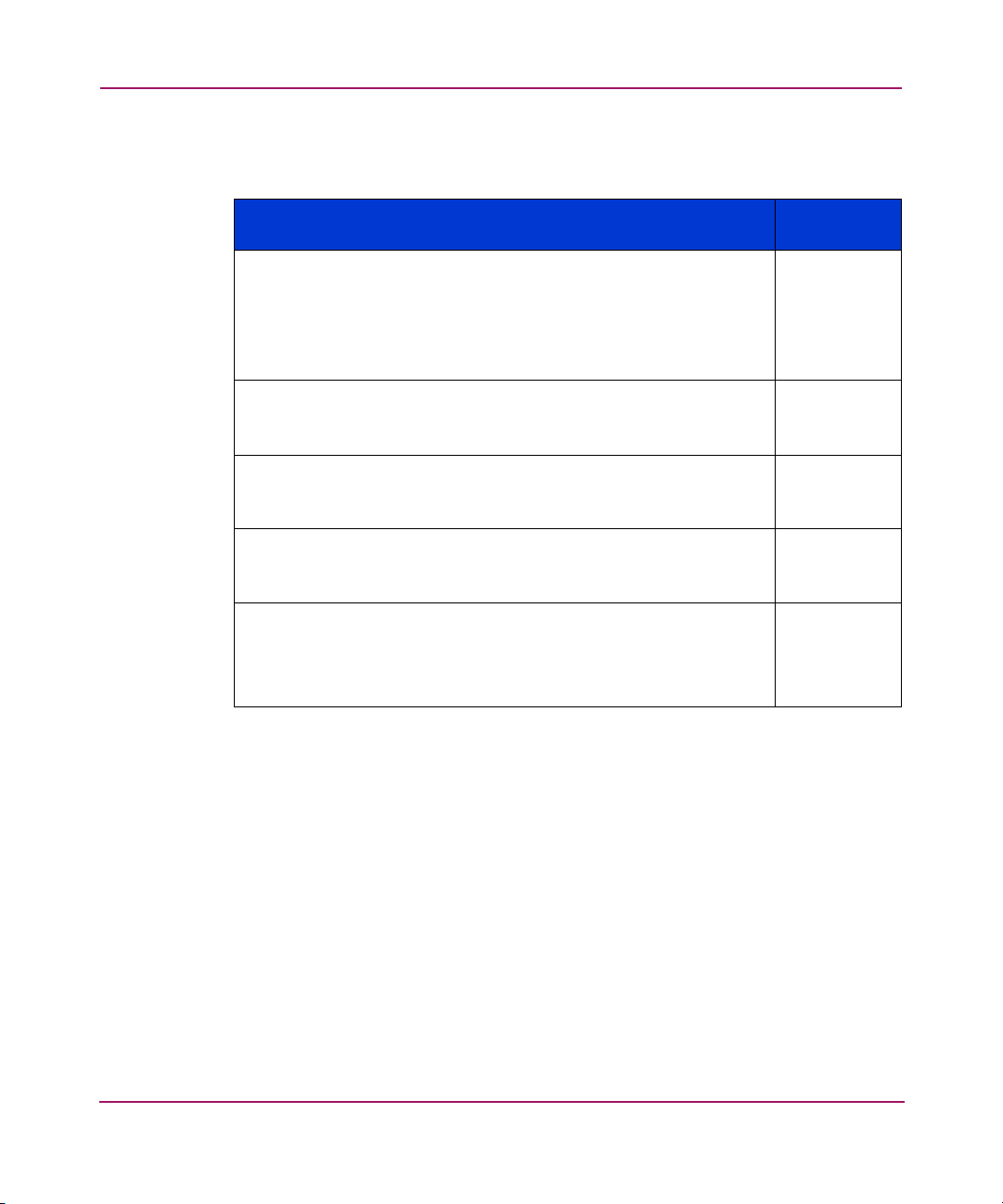
Table 4 lists the Core Switch 2/64 management tools.
Table 4: Management Options for Core Switch 2/64
Management Tool
Command line interface
For ethernet, up to two admin sessions and four user sessions at
same time. For details, refer to the
Procedures Version 3.1.x/4.1.x User Guide
HP StorageWorks Fabric OS
and the
HP
StorageWorks Fabric OS Version 3.1.x/4.1.x Reference Guide
Sectelnet and Secure Shell clients are both supported.
Fabric Manager
Fabric Manager v3.0.2c or later required. For information refer to
Fabric Manager User Guide
the
Web Tools
For information refer to the
3.1.x/4.x.1 User Guide
Standard SNMP applications
For information refer to the
.
3.1.x/4.1.x Reference Guide
Management server
For information about MS, refer to the
OS Procedures Version 3.1.x/4.1.x User Guide
StorageWorks
Fabric OS Version 3.1.x/4.1.x Reference Guide
.
HP StorageWorks Web Tools Version
HP StorageWorks MIB Version
.
HP StorageWorks Fabric
and the
HP
Out-of-ban
d Support
Ethernet or
serial
connection
.
Ethernet
Ethernet
Ethernet
Ethernet
.
Supported Features
The Core Switch 2/64 supports the following software features.Refer to the HP
StorageWorks Core Switch 2/64 Version 4.1 Release Notes to determine which
features require purchasing a license key for activation.
■ Web Tools —refer to the HP StorageWorks Web Tools Version 3.1.x/4.1.x
User Guide.
■ Zoning —refer to the HP StorageWorks Zoning Version 3.1.x/4.1.x User
Guide.
■ Secure Fabric OS —refer to the HP StorageWorks Secure Fabric OS Version
1.0 User Guide.
■ ISL Trunking —refer to the HP StorageWorks ISL Trunking Version
3.1.x/4.1.x User Guide.
32 Core Switch 2/64 V4.1 Installation Guide
Page 33

Overview
■ Fabric Watch —refer to the HP StorageWorks Fabric Watch Version 3.1/4.1
User Guide
■ Performance Monitoring —refer to the HP StorageWorks Advanced
Performance Monitoring Version 3.1.x/4.1.x User Guide.
■ Extended Fabric —refer to the HP StorageWorks Extended Fabric Version
3.1.x/4.1.x User Guide
■ Remote Switch —refer to the HP StorageWorks Remote Switch Version
3.1.x/4.1/x User Guide
33Core Switch 2/64 V4.1 Installation Guide
Page 34

Overview
34 Core Switch 2/64 V4.1 Installation Guide
Page 35

Installing and Configuring the Core Switch 2/64
The Core Switch 2/64 is 14 rack units in height and can be installed as follows:
■ Set up as a stand-alone unit on a flat surface
■ Installs in a 19 inch EIA (Electronic Industries Association) cabinet, using the
14U Rack Mount Kit provided with the Core Switch 2/64 (detailed
instructions included with kit). You can install up to two Core Switch 2/64
units in a 42U EIA cabinet.
■ Installs in a mid-mount (Telco) rack, using the Mid-mount Rack Kit, available
from the HP supplier (detailed instructions included with kit)
This chapter provides the following information:
■ Installation and Safety Considerations, page 37
■ Unpack and Verify Carton Contents, page 39
■ Installation Overview, page 43
■ Powering On for the First Time, page 67
■ Core Switch PID Format Summary, page 71
■ Configuration Overview, page 73
■ Configuring Core Switch 2/64 Network Addressing, page 75
2
■ Saving the System Configuration Files, page 85
■ Setting Up Speed Negotiation, page 87
35Core Switch 2/64 V4.1 Installation Guide
Page 36

Installing and Configuring the Core Switch 2/64
Use the following procedures in this chapter to set up and configure the Core
Switch 2/64:
■ Provides a carton contents checklist
■ Lists installation requirements
■ Outlines how to install the Core Switch 2/64 as a standalone unit, or in a 9000
Series, 42U or comparable rack
■ Outlines how to install the Core Switch 2/64 in the optional HP System/e
Rack
■ Describes how to configure Core Switch 2/64 network addressing
■ Describes how to check POST results to verify that the switch is up and
running in the SAN
■ Summarizes the Core Switch PID format
■ Outlines how to connect the Core Switch 2/64 to the Local Area Network
(LAN)
■ Describes how to connect SFPs
■ Setting up Speed Negotiation
36 Core Switch 2/64 V4.1 Installation Guide
Page 37
Installing and Configuring the Core Switch 2/64
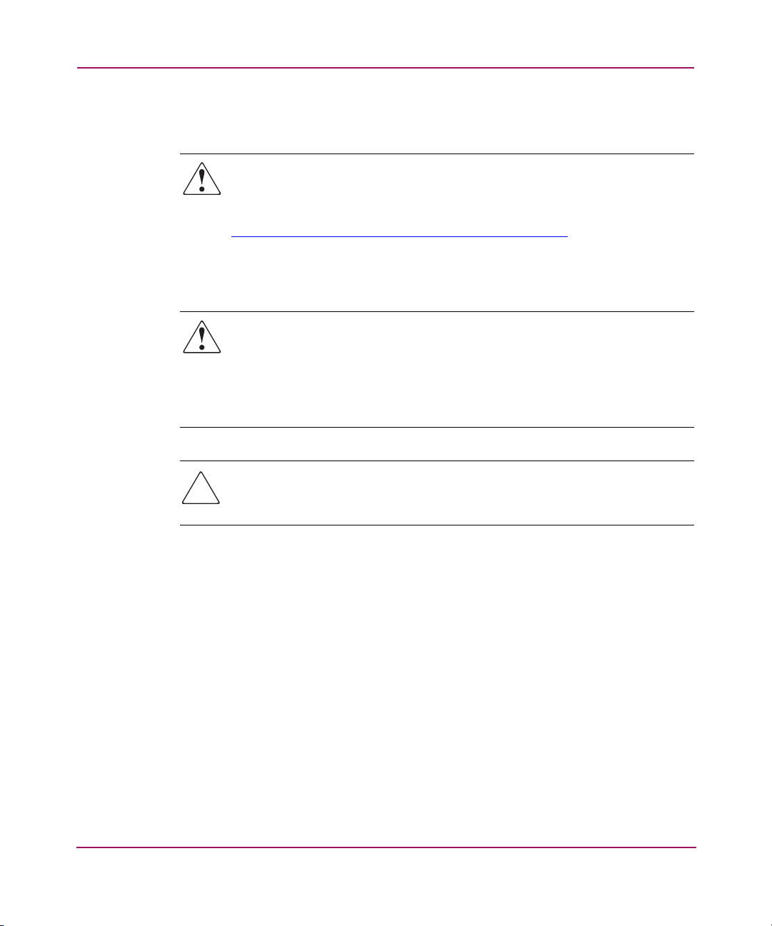
Installation and Safety Considerations
WARNING: For safety reasons, when installing this product in an equipment
rack, you must consider rack stability against tipping. Please refer to the user
manual provided with the equipment rack to determine rack stability
(available through the HP Web site at:
http://www.hp.com/racksolutions/prodinfo/racks/index.html
If the necessary stability is not achieved, through the placement of additional
equipment or ballast, the equipment rack must be anchored to the building
structure before operation.
WARNING: A fully populated HP StorageWorks Core Switch 2/64 weighs
approximately 250 pounds (113 kg) and requires a minimum of two people
and mechanical lift to install it.
Before installing, verify that the additional weight of the chassis does not
exceed the cabinet’s weight limits or unbalance the cabinet, including when
some of the cards or power supplies are partially extended out of the chassis.
).
Caution: To ensure adequate cooling, install the chassis with the port side
facing the aisle into which exhaust air is released (usually called the service
aisle). This prevents the fans from pulling in heated exhaust air.
You must complete the following steps to ensure correct installation and
operation:
■ Provide a space that is 14U high, 29 inches deep, and 19 inches wide
(IU = 1.75 inches). Also provide an additional 1U for cable management.
■ If installing in a cabinet:
— Ensure the space in the 19 inch (48.3 cm) EIA cabinet is 14U high, with a
minimum distance of 28.25 inches (71.76 cm) between the front and back
rails, and a maximum distance of 29.88 inches (75.90 cm).
— Verify that the additional weight of the chassis does not exceed the
cabinet’s weight limits.
— Ensure that all equipment installed in the cabinet is grounded through a
reliable branch circuit connection. Do not rely on a secondary connection
to a branch circuit, such as a power strip.
37Core Switch 2/64 V4.1 Installation Guide
Page 38

Installing and Configuring the Core Switch 2/64
■ Ensure that two dedicated electrical branch circuits with the following
characteristics are available for use:
— 200 to 240 VAC, 50 - 60 Hertz.
— Protected by a circuit breaker in accordance with local electrical codes.
— Supply circuit, line fusing, and wire size that are adequate according to
the electrical rating on the chassis nameplate.
— Grounded outlets installed by a licensed electrician and compatible with
the power cords.
— Located close to the 14U HP StorageWorks Core Switch 2/64 chassis and
easily accessible.
Note: To maximize fault tolerance, connect each power cord to a separate power
source.
■ Ensure the HP StorageWorks Core Switch 2/64 has access to a minimum
airflow of 350 cubic feet per minute.
■ Ensure the air temperature measured at the blower inlet does not exceed 40
degrees Celsius during operation.
38 Core Switch 2/64 V4.1 Installation Guide
Page 39

Unpack and Verify Carton Contents
Use these steps to unpack and verify Core Switch 2/64 shipping carton contents.
Note: Obtain a 1/2 inch socket wrench to remove the pallet bolts.
1. Remove the upper portion of the packing crate while the switch is still in the
shipping area to reduce clutter at the installation site.
a. Open the latches that hold the top of the crate to the pallet. To open a
latch, pull the handle out, turn it to the left, then slide the latch open.
b. Lift the top of the crate off the pallet.
Note: Leave the foam on top of the chassis to hold the kits in place during
transportation to the installation area.
2. Remove the packing foam, antistatic plastic, 14U Rack Mount Kit, and
Accessory Kit.
3. Locate the hinges on the crate. Remove the crate hinges as follows:
Installing and Configuring the Core Switch 2/64
a. Pull the handle out, and turn counter-clockwise.
b. Slide the hinge open and lift up.
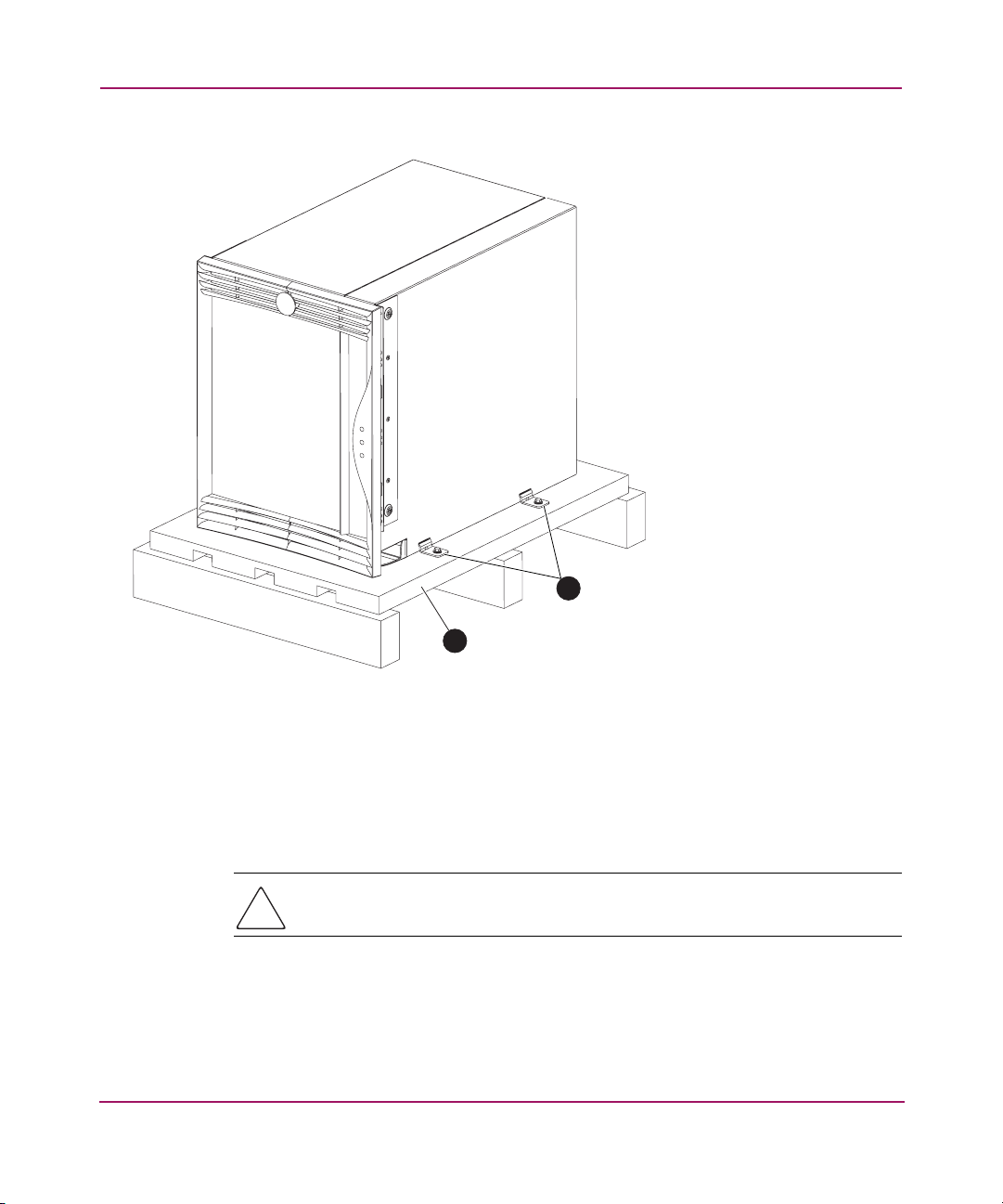
4. Unscrew the four bolts securing the Core Switch 2/64 to the pallet. See
Figure 3.
39Core Switch 2/64 V4.1 Installation Guide
Page 40
Installing and Configuring the Core Switch 2/64
1
2
SHR-2507A
1 Pallet bolts (two on each side)
2 Pallet
Figure 3: Releasing the crate from the pallet
5. Remove the brackets.
Caution: You must remove the chassis door before lifting the chassis off the
pallet. See the section Removing the Chassis Door on page 45.
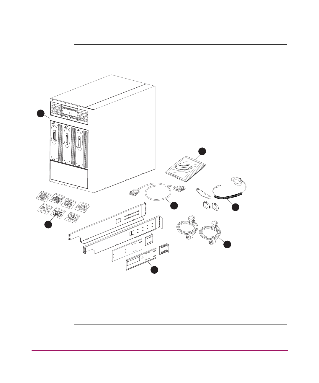
6. Verify that the carton contains the items shown in Figure 4 and Table 5.
40 Core Switch 2/64 V4.1 Installation Guide
Page 41
Installing and Configuring the Core Switch 2/64
Note: If any items are damaged or missing, please contact your authorized reseller.
1
2
4
7
6
3
5
SHR-2506A
Figure 4: Core Switch 2/64 carton contents
Note: Additional mounting hardware may be included with the switch for mounting in
HP racks.
41Core Switch 2/64 V4.1 Installation Guide
Page 42
Installing and Configuring the Core Switch 2/64
Table 5: Core Switch 2/64 Carton Contents Checklist
Item Summary
1
2
3
4
5
6
7
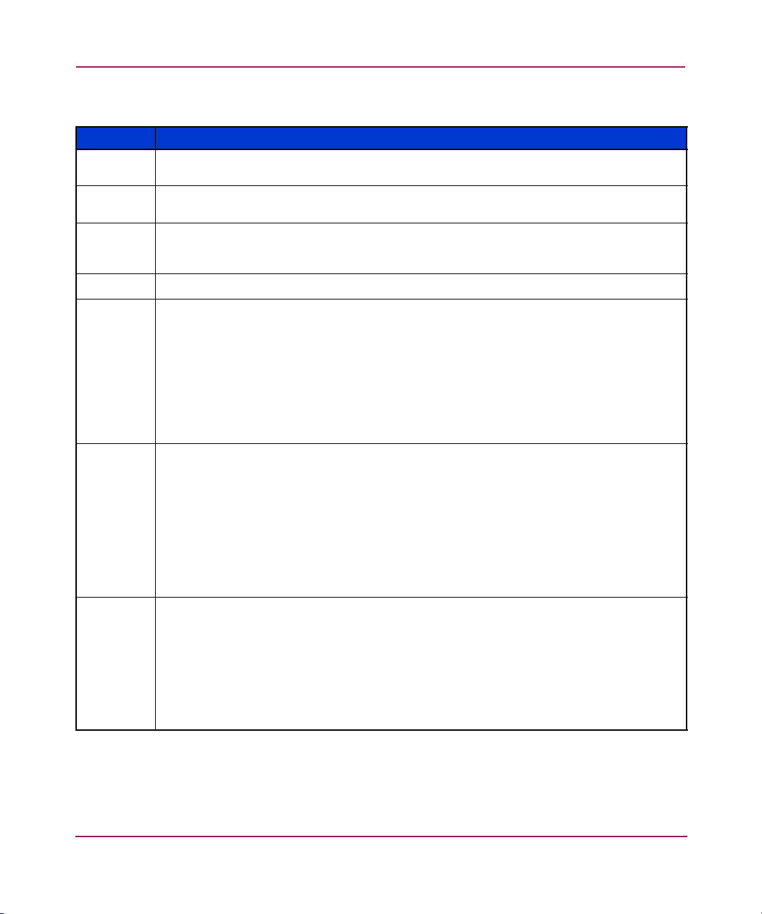
Core Switch 2/64 populated with two 16-port cards, two CP cards, four power
supplies and three blower assemblies.
StorageWorks Fibre Channel Core Switch 2/64 Installation Guide, Release Notes
software CD, and license
One Accessory Kit containing one ESD grounding strap, sixteen cable guides, and two
power cord retainers, with Phillips screws (#4-40), and #1 Phillips screwdriver as a
required tool
RS-232 serial cable with an RJ-45 adapter
AC power cords (2) Currently two set of power cords that are shipped with the Core
Switch 2/64 switch. One set is for pmHP & the other set is for pmCPQ.
For the pmHP Core Switch, two jumper cables (C19 – C20) are provided to connect
from the switch to the PDU. The PDU that we recommend is E7671A. Two E7671A are
recommended for power redundancy. The recommended power cords to connect from
the PDU to the wall are E7803A, E7805A, E7806A, E7808A, E7809A. Both are
standard US receptacles. These cables are then plugged into a PDU (Power Distribution
Unit) in the rack, which is customized by country.
14U Rack Mount Kit containing: Left rack mount shelf bracket, (1); Right rack mount
shelf bracket, (1)
• Left upper rack mount bracket assembly, includes: Left upper rack mount bracket
(flat); Left upper rack mount bracket (L-shaped); Screw (torque to 32 inch-pounds)
• Right upper rack mount bracket assembly, includes: Right upper rack mount bracket
(flat); Right upper rack mount bracket (L-shaped); Screw (torque to 32 inch-pounds)
• M5 Tinnermans (0590-2318) and M5 Torx screws (0515-0671) are required
pieces of rack mount kit hardware.
• Seven pouches containing 14U Rack Mount Kit hardware; #10-32 x 5/16 Phillips
flathead screws (8); #10-32 x 5/16 Phillips panhead screws with washers (4)
• For use with the 9000 Series 42U rack (or racks with square holes): #10-32 x 5/16
retainer nuts; #1/4-20 x 0.500 Phillips panhead screws with glue (16); 0.375-inch
square washers (16)
• For use with rack with round holes: #10-32 clip nut (package of 20, only 4
required); #1/4-20 x 1/2 inch Phillips panhead screws, with lockhead washers (16)
,
42 Core Switch 2/64 V4.1 Installation Guide
Page 43

Installation Overview
Install the Core Switch 2/64 in one of the following ways
■ As a standalone unit on a stable table or lab workbench
■ In a rack using the 14U Rack Mount Kit supplied with the switch
■ As a fixed component in the System/e rack
Selecting an Operating Location
Verify that the switch location meets the following requirements:
■ Adequate supply circuit, line fusing, and wire size, as specified by the
electrical rating on the switch nameplate.
■ Air flow of at least 350 cubic feet per minute, available in the immediate
vicinity of the Core Switch 2/64.
■ If installing the switch in the 9000 Series rack, or comparable Electronics
Industries Association (EIA) rack:
— All equipment installed in the rack should have a reliable branch circuit
ground connection, and should not rely on a connection to a branch
circuit, such as a power strip.
Installing and Configuring the Core Switch 2/64
— The rack should be balanced and the installed equipment within the rack’s
Cooling Requirements
Install the switch so that air intake and exhaust for all components in the rack is
flowing in the same direction.
Note: To ensure adequate cooling, install the chassis with the port side facing the
aisle into which exhaust air is released (usually called the “service aisle”). This
prevents the fans from pulling in heated exhaust air.
weight limits. Ensure that the rack is mechanically secured to insure
stability in the event of an earthquake.
43Core Switch 2/64 V4.1 Installation Guide
Page 44

Installing and Configuring the Core Switch 2/64
Power Requirements
Two AC power cords connect to the switch. The AC power source must meet
these requirements:
Note: Installing each power cord using two separate sources ensures power supply
redundancy.
■ 200 to 240 VAC, 50 - 60 Hertz
■ Protected by a circuit breaker in accordance with local electrical codes
■ Supply circuit, line fusing, and wire size that are adequate according to the
electrical rating on the chassis nameplate
■ Grounded AC outlets installed by a licensed electrician and compatible with
the power cords
The switch includes a universal power supply capable of functioning worldwide
without voltage jumpers or switches. The power supply is auto ranging in terms of
accommodating input voltages and line frequencies.
Two jumper cables (C19 – C20) are provided to connect from the switch to the
PDU. The recommended PDU is E7671A. Two E7671A PDUs are recommended
for power redundancy. The recommended power cords to connect from the PDU
to the wall are E7803A, E7805A, E7806A, E7808A, E7809A.
It is not recommended to connect the switch to the wall because it would require
two dedicated wall outlets. Using the PDU, a customer can connect more devices
to a power source.
Installing the Switch as a Stand-alone Unit
The following items are required for this setup:
■ Core Switch 2/64
■ AC power cords and cables supplied with the switch
Caution: You must remove the chassis door before lifting the chassis off the
pallet. See the next section, Removing the Chassis Door, on page 45.
44 Core Switch 2/64 V4.1 Installation Guide
Page 45
Removing the Chassis Door
You must remove the chassis door before lifting the switch off the pallet. Use
these steps to remove the chassis door.
Note: To ensure adequate cooling, install the chassis with the port side facing the
aisle into which exhaust air is released (usually called the “service aisle”). This
prevents the fans from pulling in heated exhaust air.
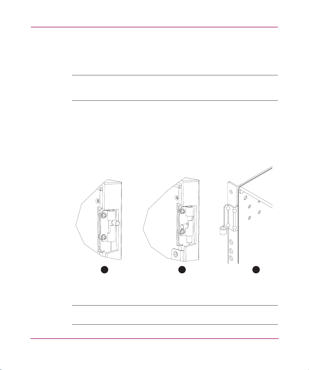
1. Open the door to a 90° angle.
2. Push the spring-loaded lever on the upper hinge up and into the notch in the
hinge. See Figure 5.
3. Push the spring-loaded lever on the lower hinge down and into the notch in
the hinge, supporting the door to prevent it from falling. See Figure 5 for the
complete chassis door removal sequence.
Installing and Configuring the Core Switch 2/64
1 2 3
SHR-2508A
Figure 5: Sequence for detaching the chassis door from the hinges
Note: Put the chassis door aside. You will need to reinstall it after moving the Core
Switch 2/64 off the pallet.
45Core Switch 2/64 V4.1 Installation Guide
Page 46

Installing and Configuring the Core Switch 2/64
4. Position the pallet so that the bottom of the chassis is level with the
installation surface.
5. If the chassis is on a pallet jack or lift, stabilize the pallet jack or lift to prevent
it from moving during the transfer.
WARNING: A fully populated StorageWorks 14U chassis weighs
approximately 250 lbs (113 kg) and requires a minimum of two people to
safely slide it from one surface to another.
Installing the Core Switch 2/64 on a Flat Surface
Use these steps to install the Core Switch 2/64 on a flat surface.
Note: The Core Switch 2/64 must be placed on a stable, flat surface, with the blower
side of the chassis having access to cool air. Orient the switch so that the port side
faces the service aisle.
1. Remove the switch chassis door, if you have not already done so. Removing
the Chassis Door, on page 45
.
2. Place the Core Switch 2/64 on a flat, sturdy surface like a table or lab bench.
3. Connect the two power cables to the power supply inlets on the switch.
Note: It is recommended to power the switch using two separate power sources,
ensuring redundancy.
4. Connect the two power cables to corresponding power outlets. Make sure that
the power cable is routed so that it is not exposed to stress.
5. Turn on power to the switch. The switch automatically runs a Power On Self
Test (POST).
Note: Do not connect the switch to the network until the IP address is correctly set. For
instructions on how to set the IP address, see Configuring Core Switch 2/64 Network
Addressing, on page 75 later in this chapter.
46 Core Switch 2/64 V4.1 Installation Guide
Page 47

6. Reinstall the chassis door as described in the section Reinstalling the Chassis
Door, on page 60.
Installing the Core Switch 2/64 in a Rack
Read these sections for specific information on installing the Core Switch 2/64 in
a 9000 Series (42U), or comparable rack.
Pre-installation Checklist
Review the following checklist before installing the switch.
■ Prepare a site plan. For additional product information, go to:
http://www.hp.com/products1/storage/products/san/fibreswitches/coreswitch2_64/in
dex.html
■ Verify that required technical personnel (two technicians) are available and
scheduled for the installation.
■ Obtain the required fibre-optic cables (multimode or single-mode). Verify
cable length and required connectors.
■ If applicable, obtain the necessary remote workstations or Simple Network
Management Protocol (SNMP) workstations. Workstations are
customer-supplied and connected through a corporate or dedicated LAN.
.
Installing and Configuring the Core Switch 2/64
■ Verify that the front panel air temperature does not exceed 40 °C (104 °F)
during operation.
■ Verify that all equipment installed in the rack has a reliable branch circuit
ground connection, and does not rely on a connection to a branch circuit, such
as a power strip.
■ Verify that the rack is balanced.
■ Check that the rack is mechanically secured to insure stability in the event of
an earthquake.
Items Required for Installation
Locate the following items before beginning the install procedure.
■ Lift device—A fully populated Core Switch 2/64 weighs approximately 250
lbs. The switch requires a minimum of two people and a hydraulic or assisted
lift to aid in moving the switch from the pallet to its operating location.
47Core Switch 2/64 V4.1 Installation Guide
Page 48

Installing and Configuring the Core Switch 2/64
■ Two power outlets—Identify one power outlet for each of the two power
cords. Installing each power cord at two separate sources ensures power
supply redundancy.
■ Torque driver—Required to secure the 14U Rack Mount Kit hardware to the
rack rails.
■ Fibre-optic protective plugs—For safety and port transceiver protection,
fibre-optic protective plugs must be inserted in all Core Switch 2/64 ports
without fibre-optic cables attached. The Core Switch 2/64 ships with
protective plugs installed in all ports.
■ Standard flat-tip and cross-tip Phillips screwdrivers—Required to remove,
replace, adjust or tighten various FRUs, chassis, or rack components.
■ Electrostatic discharge (ESD) grounding strap—Required when working in
and around the Core Switch 2/64 card cage. Use the ESD strap supplied with
the switch.
■ Maintenance terminal (desktop or notebook computer)— Required to
configure Core Switch 2/64 network addresses and acquire event log
information through the serial port. Computer requirements include:
— Microsoft Windows 98, Windows NT 4.0, Windows 2000, or Windows
Millennium Edition operating system installed
— RS-232 serial communication software (for example, ProComm Plus or
HyperTerminal).
■ A 9000 Series 42U rack, or any rack with the following specifications,
— A minimum depth of 29 inches
— 14 rack units (14U) high
— 19 inches wide.
Important Rack Mount Guidelines
Review the following rack mount guidelines before proceeding with the
installation.
48 Core Switch 2/64 V4.1 Installation Guide
Page 49

Installing and Configuring the Core Switch 2/64
WARNING: A fully populated Core Switch 2/64 weighs approximately 250
lbs and requires a minimum of two people and a hydraulic or assisted lift to
install it.
Before installing, verify that the additional weight of the chassis does not
exceed the rack’s weight limits or unbalance the rack, including when some of
the cards or power supplies are partially extended out of the chassis.
■ Check that a minimum distance of 28.25 inches is between the front and back
rails.
■ Verify that the additional weight of the chassis does not exceed the rack’s
weight limits.
■ Check that all equipment installed in the rack is grounded through a reliable
branch circuit connection. Do not rely on a secondary connection to a branch
circuit, such as a power strip.
■ Verify that space is in the rack. The Core Switch 2/64 is 14U, or 24.11 inches
high.
■ Verify that the rack is stable.
■ M5 Tinnermans (0590-2318) and M5 Torx screws (0515-0671) are required
pieces of rack mount kit hardware.
■ Verify that all other equipment installed in the rack is connected to a reliable
ground connection; do not rely on connections to a branch circuit, such as a
power strip.
■ Plan for cable management before installing the chassis. Cables can be
managed in a variety of ways, such as by routing cables below the chassis, to
either side of the chassis, through cable channels on the sides of the rack.
■ Verify that the Core Switch 2/64 access to a minimum airflow of 350 cubic
feet per minute.
■ Ensure adequate cooling by installing the chassis with the port side facing the
aisle into which exhaust air is released (usually called the “service aisle”).
This prevents the fans from pulling in heated exhaust air.
49Core Switch 2/64 V4.1 Installation Guide
Page 50

Installing and Configuring the Core Switch 2/64
Installing the Core Switch 2/64 in a 9000 Series, 42U Rack
Use the following procedure to install the Core Switch 2/64 in the 9000 Series, or
comparable 42U rack using the 14U Rack Mount Kit supplied with the switch.
Allow approximately 45 minutes to complete this procedure.
Note: These instructions describe how to install the switch in the bottom area of the
rack (section closest to the floor). You may need to orient 14U Rack Mount Kit
hardware based on your particular rack’s configuration.
Attaching the Rack Mount Shelf Brackets
Use these steps to install the rack mount shelf brackets.
Caution: You can install up to two 2/64 switches in the 9000 Series, or
comparable 42U rack.
1. If you have not already done so, remove the chassis door. See the “Removing
the Chassis Door,” instructions listed previously in this chapter.
2. Locate the left and right rack mount shelf brackets. Refer to Figure 4 and
Table 5 to identify the hardware.
3. Loosen the adjusting screws on the left and right rack mount shelf brackets,
and adjust the length of the brackets according to the depth of the rack. See
Figure 6.
4. Locate the small, round marker holes on the rack rails. Each marker hole
delineates the beginning of one rail unit, or U. Leave 1U of space free at the
bottom of the rack.
5. Count up five square holes from the 1U location. Align the left rack mount
shelf brackets with the fifth square hole.
6. Attache rack mount
a. For rails with round holes; Position the left and right Rack Mount Shelf
Brackets with notched portion toward exhaust aisle (see Figure 6) and
attach to cabinet rails, using six 1/4-20 x 0.500-inch (1.27 cm) screws
with lock washers per bracket (two on the notched end and four on the
other end).
50 Core Switch 2/64 V4.1 Installation Guide
Page 51
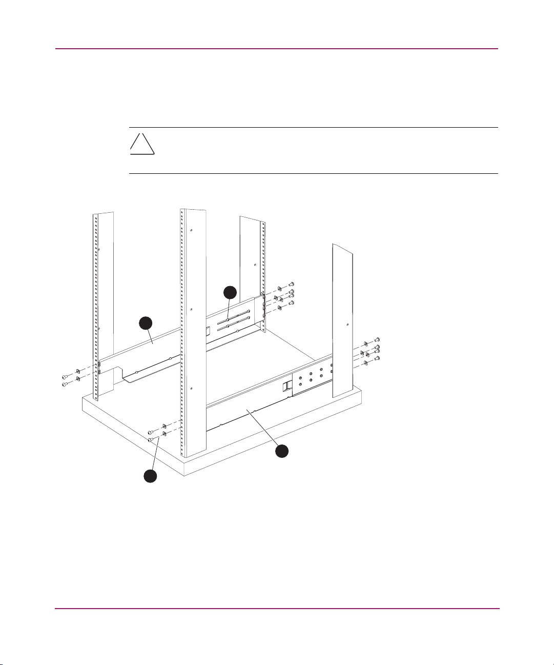
Installing and Configuring the Core Switch 2/64
b. For rails with square holes, attach the left rack mount shelf bracket to the
rack rails using six 1/4-20 x 0.500-inch screws and six square washers.
See Figure 6.
Caution: All 14U Rack Mount Kit hardware and screws are supplied with the
Core Switch 2/64. Use the exact screws specified in the procedure. Using
longer screws may damage the chassis.
2
1
4
1 Left rack mount shelf bracket
2 Adjusting screws
Figure 6: Installing the left and right rack mount shelf brackets
3
SHR-2509A
3 Right rack mount shelf bracket
4 1/4-20 x .500-inch screws and washers (6)
51Core Switch 2/64 V4.1 Installation Guide
Page 52

Installing and Configuring the Core Switch 2/64
7. Tighten the screws to a torque of 80-inch pounds.
8. Repeat steps 5 through 7 to install the right rack mount shelf bracket.
Note: When finished securing the rack mount shelf brackets, remember to tighten the
adjustment screws you loosened in step 3, and torque to 32 inch-pounds.
52 Core Switch 2/64 V4.1 Installation Guide
Page 53
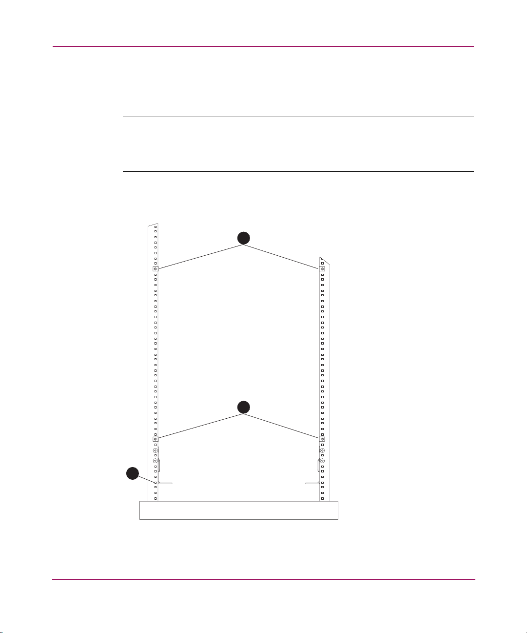
Installing and Configuring the Core Switch 2/64
For Rails with Square Holes—Attaching the Retainer Nuts
If installing 14U Rack Mount Kit in rails with square holes (9000 Series, 42U
rack), attach retainer nuts to vertical rails on service side of the rack as follows.
Note: Use the retainer nuts for rails with square holes only, (9000 Series, 42U rack).
Read the next section, For Rails with Round Holes—Attaching the Clip Nuts, on
page 54 if installing switch in rack rails with round holes. Count up 41 square holes
from the 1U location.
9. Attach the four retainer nuts to the two rails at the front of the rack (service
aisle side). See Figure Figure 7.
1
2
3
Figure 7: Installing the retainer nuts on the rails
1 Upper retainer
nuts, installed in
hole #41
2 Lower retainer
nuts, installed in
hole #9
3 1U location
53Core Switch 2/64 V4.1 Installation Guide
Page 54

Installing and Configuring the Core Switch 2/64
For Rails with Round Holes—Attaching the Clip Nuts
If installing the 14U Rack Mount Kit in rails with round holes, refer to this
section. Attach the clip nuts to the vertical rails on the service side of the rack as
follows.
■ Use the clip nuts for rails with round holes only.
■ Refer to the section For Rails with Square Holes—Attaching the Retainer
Nuts, on page 53 if installing the switch in rack rails with square holes.
1. Count up 41 round holes from the 1U location.
2. Attach the four clip nuts to the two rails at the front of the rack (service aisle
side). See Figure 7.
Note: Cables can be routed down through the cable management tray or through the
holes in the sides of the chassis. If the cables will be routed down through the cable
management tray, allow adequate space below the chassis for cable management.
Attaching the Upper Rack Mount Bracket Assemblies to the Chassis
Use these steps to attach the upper rack mount brackets to the chassis. The upper
rack mount bracket assemblies consist of the following:
■ One right flat upper rack mount bracket attached to an L-shaped bracket
■ One left flat upper rack mount bracket attached to an L-shaped bracket
Note: To compete this procedure, you must first detach the L-shaped brackets from the
upper rack mount bracket assemblies.
1. Use a Phillips head screwdriver to remove the screws securing the left and
right upper rack mount brackets to the L-shaped brackets. Detach the
L-shaped brackets from the assembly, and put them aside.
Note: You reinstall the L-shaped brackets to the rack rails in step 5.
2. Save the screws for attaching the bracket assemblies to the chassis (see step 1
in the section Securing the Chassis to the Rails on page 58).
54 Core Switch 2/64 V4.1 Installation Guide
Page 55
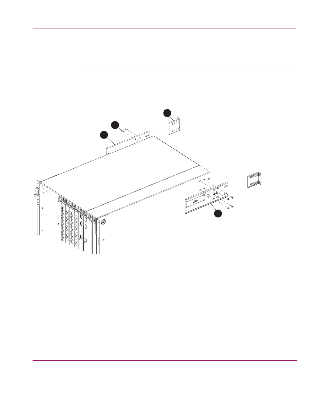
Installing and Configuring the Core Switch 2/64
3. Use four #10-32 x 5/16 inch screws to secure the right and left flat upper rack
mount brackets to the chassis. See Figure 8.
Note: Orient the slotted holes in the brackets toward the blower side of the chassis
(see Figure 8 for orientation).
3
2
1
1 Left flat upper rack mount bracket
2 #10-32 x 5/16 inch screws (4)
Figure 8: Attaching the left and right flat upper rack mount brackets
4. Tighten the screws, and torque to 32 inch-pounds.
4
SHR-2511A
3 Detached L-shaped brackets (1 of 2)
4 Right flat upper rack mount bracket
55Core Switch 2/64 V4.1 Installation Guide
Page 56

Installing and Configuring the Core Switch 2/64
5. Attach the two L-shaped brackets to the rack rails farthest from the service
aisle. See Figure 9.
— For rails with square holes:
Attach the two L-shaped brackets to the rack rails, with two of the
#1/4-20 x 1/2 inch Phillips panhead screws, and two square washers
per bracket. Tighten the screws to a torque of 80 inch-pounds.
— For rails with round holes:
Attach the two L-shaped brackets to the rack rails, using two of the
#1/4-20 x 1/2 inch Phillips panhead screws (Item 8) per bracket.
Tighten the screws to a torque of 80 inch-pounds.
6. Route any cables or cords through the cabinet or along any other route that
will be difficult to reach after the chassis is installed. Leave enough cable
allowance to plug and unplug cables from switch.
56 Core Switch 2/64 V4.1 Installation Guide
Page 57
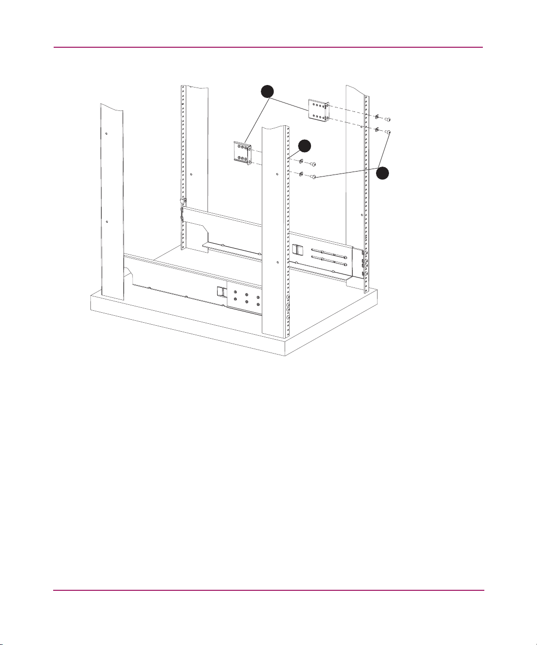
Installing and Configuring the Core Switch 2/64
1
2
3
1 Two L-shaped brackets
2 Aligning top screw in hole #37
Figure 9: Attaching L-shaped brackets to rails
SHR-2512A
3 1/4-20 x 1/2 inch Phillips panhead screws
and square washers
57Core Switch 2/64 V4.1 Installation Guide
Page 58
Installing and Configuring the Core Switch 2/64
Finalizing the Rack Mount Procedure
Read these sections to install the Core Switch 2/64 into the 9000 Series 42U, or
comparable rack.
WARNING: A fully populated SAN Core 2/64 weighs approximately 250
lbs and requires a minimum of two people and a hydraulic or assisted lift to
install it.
Before installing, verify that the additional weight of the chassis does not
exceed the rack’s weight limits or unbalance the rack, including when some of
the cards or power supplies are partially extended out of the chassis.
Sliding the Switch into the Rack
1. Before lifting the chassis into the rack, determine an easy access route for
cables or cords. Make sure that cables do not get pinned under the weight of
the chassis.
2. Position the lift device next to the Core Switch 2/64.
3. Position one technician at the front of the chassis, and the second technician at
the rear of the chassis. Carefully move the chassis onto the lift device.
4. Use the lift-assist device to raise the chassis until the bottom of the chassis is
level with the shelf-like surfaces of the rack mount shelf brackets.
5. Slide the chassis onto the two rack mount shelf brackets.
Securing the Chassis to the Rails
1. Attach the two flat upper rack mount brackets (that you installed on the
chassis earlier) to the two L-shaped brackets installed onto the rack rails. Use
the two screws set aside in step 1 of the section Attaching the Upper Rack
Mount Bracket Assemblies to the Chassis on page 54. See Figure 10.
58 Core Switch 2/64 V4.1 Installation Guide
Page 59
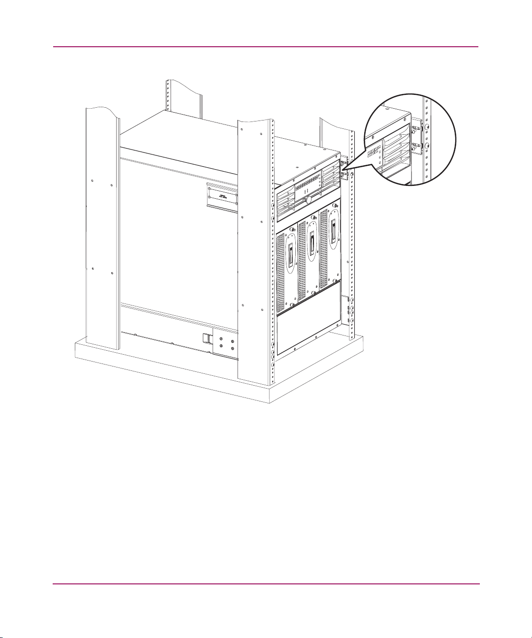
Installing and Configuring the Core Switch 2/64
SHR-2513A
Figure 10: Attaching the upper rack mount bracket to the L-shaped brackets
2. Tighten screws, and torque to 32 inch-pounds.
59Core Switch 2/64 V4.1 Installation Guide
Page 60
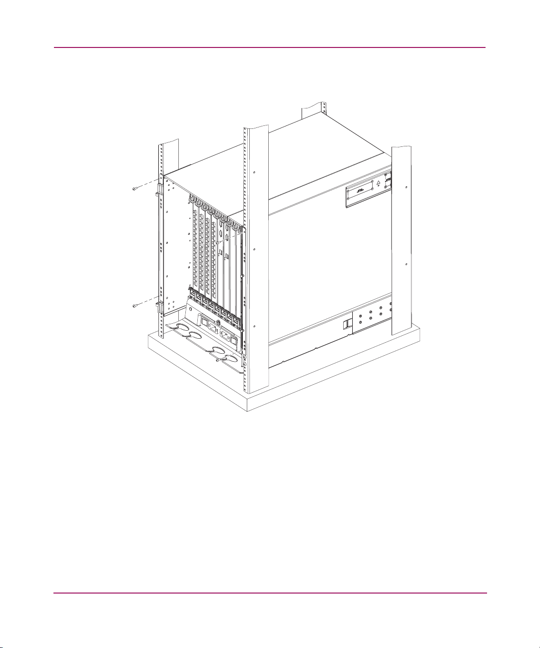
Installing and Configuring the Core Switch 2/64
3. Secure the chassis’ port side to the rack rails using two #10-32 x 5/8 inch
screws on each side.
SHR-2514A
Figure 11: Securing the chassis port side to rack rails
4. Tighten the screws, and torque to 32 inch-pounds. See Figure 11 for screw
locations.
Reinstalling the Chassis Door
1. Verify that the spring-loaded pins on both door hinges are retracted (push
levers into notches).
2. Align the door hinges with the chassis portion of the hinges.
3. Push the levers out of the notches to release the pins.
60 Core Switch 2/64 V4.1 Installation Guide
Page 61
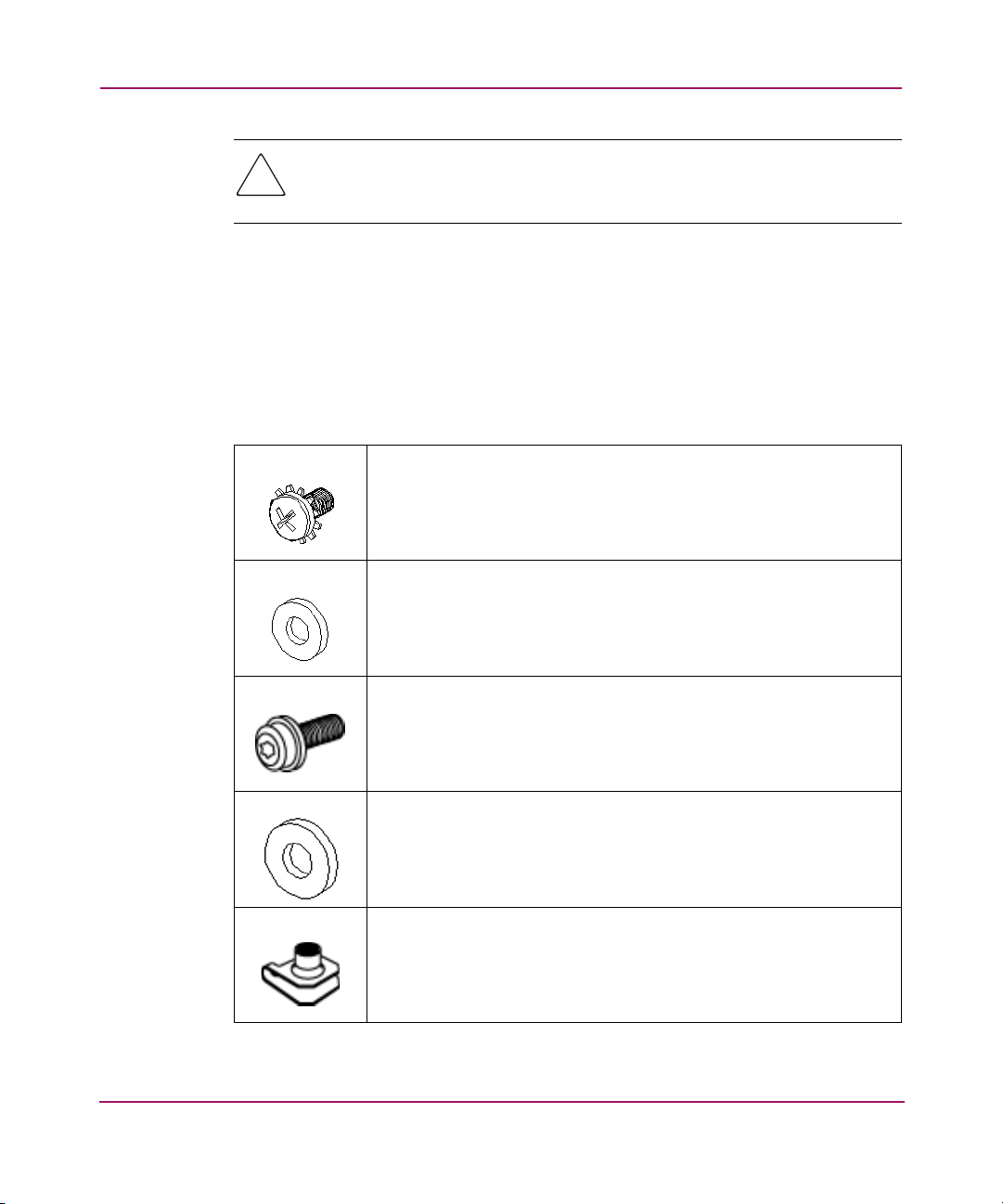
Installing and Configuring the Core Switch 2/64
Caution: Do not connect the switch to the network until the IP addresses are
correctly set. Refer to the section Configuring Core Switch 2/64 Network
Addressing on page 75.
Installing the Switch in the Optional HP System/e Rack
This section provides instructions for installing the switch in the HP System/e
rack. The following hardware is required to install the optional HP System/e Rack
Mount Kit:
■ Rails, rear mounting brackets
■ Rail mounting hardware, as listed in the following table:
(6) #8-32 x 5/16 Phillips pan-head screw with captive star lock
washer
(6) #8 Flat washer
(6) M5 Torx head screw with captive lock washer
(2) Rubber washer
(4) M5 U-type Tinnerman clip
61Core Switch 2/64 V4.1 Installation Guide
Page 62
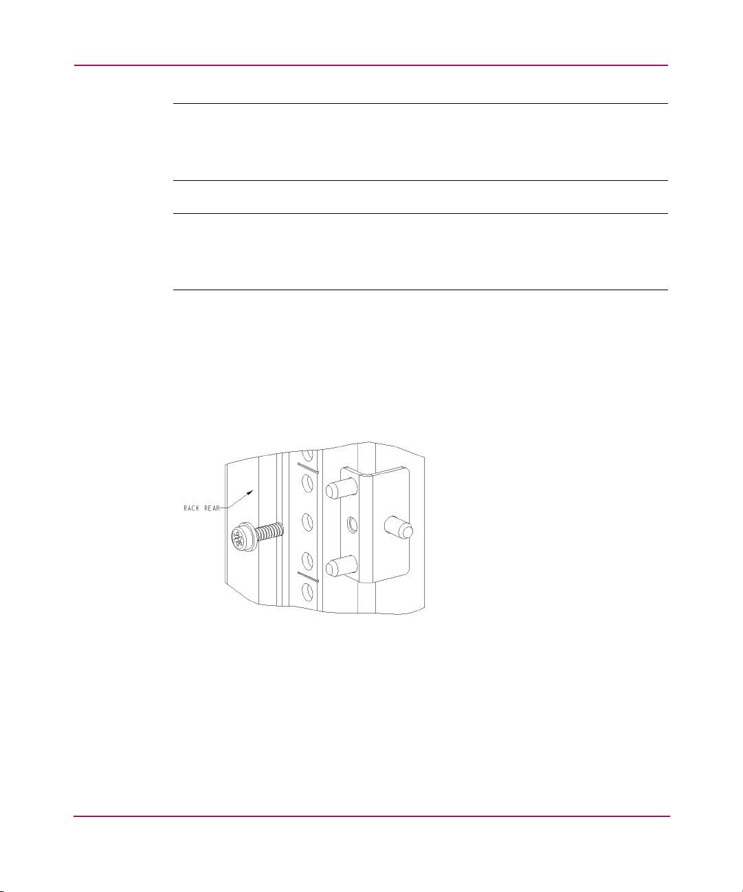
Installing and Configuring the Core Switch 2/64
Note: For proper airflow, the SFP media side of the SAN Switch 2/64 must face the
rear of the rack. This mounting allows air to enter from the front of the rack and to
exhaust at the rear of the rack, similar to other rack-mounted equipment. This prevents
switch overheating, which may cause it to fail.
Note: The HP System/e Rack installation procedure in this section provides general
guidelines for installing a switch in the rack. Please note that the figures show
installation of an edge switch. Installing the Core Switch 2/64 in the HP System/e
Rack works similarly.
Use these steps to install the switch in the HP System/e rack.
1. Verify that all required hardware is available.
2. Choose a mounting location in the rack for the switch.
3. Install each of the two mounting brackets with (1) M5 Torx head screw with
captive lock washers as shown in Figure 12.
Figure 12: Installing the mounting brackets
62 Core Switch 2/64 V4.1 Installation Guide
Page 63
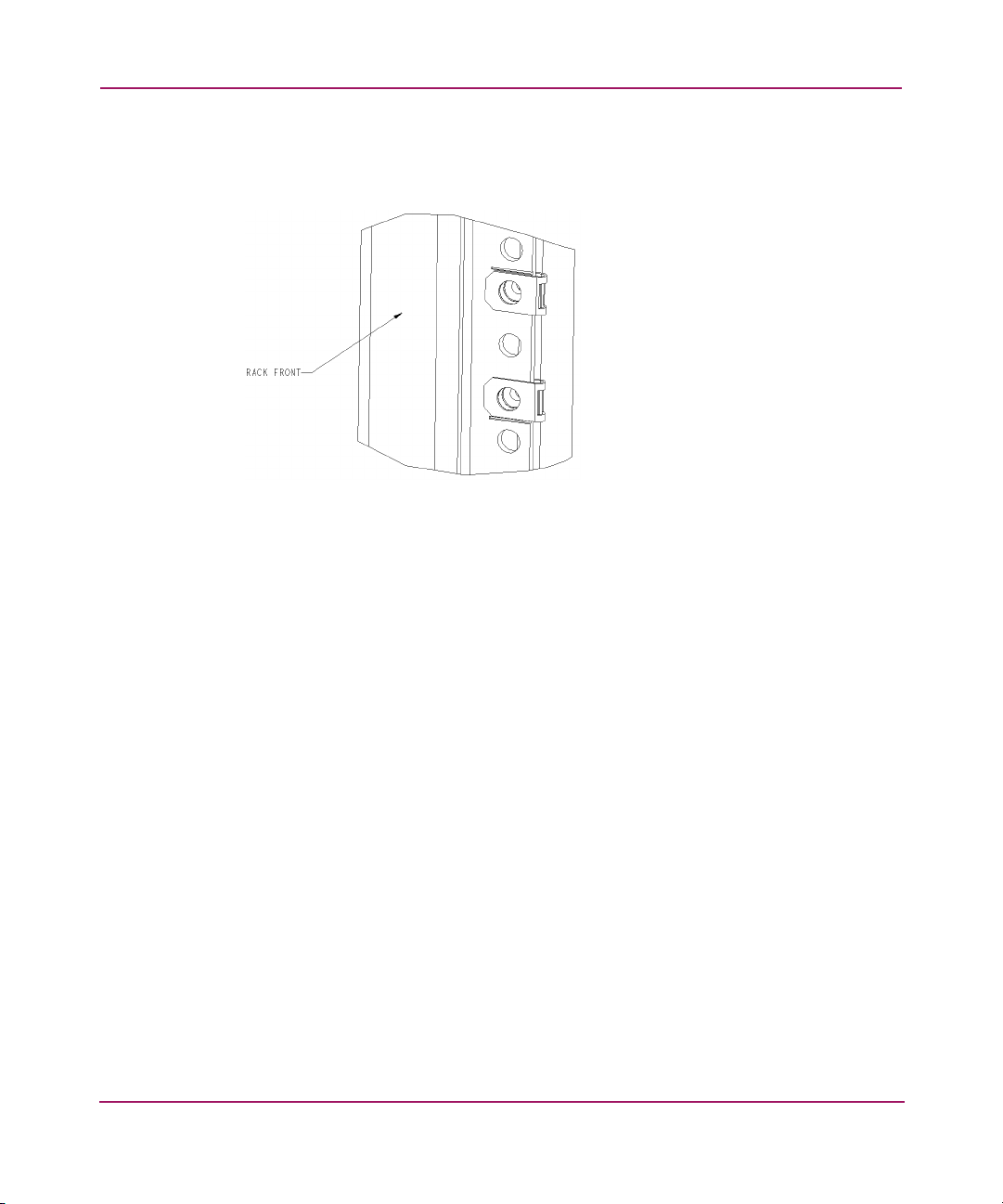
Installing and Configuring the Core Switch 2/64
4. Install two M5 U-type Tinnerman clips for each of the front columns of the
rack in the top and bottom positions of the three-hole pattern as shown in
Figure 13.
Figure 13: Installing the Tinnerman clips
5. Assemble the outer rails by completing the following steps:
a. As an aid in assembly, two rubber washers have been included to help
keep the rear slotted portion of the outer rail flush against the rear rail-tray
brackets. Install them as shown in Figure 14.
63Core Switch 2/64 V4.1 Installation Guide
Page 64
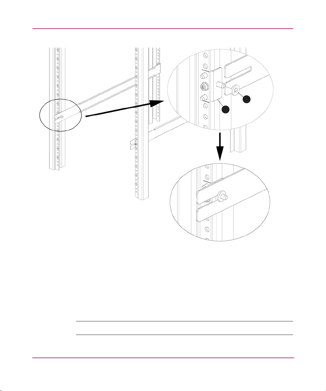
Installing and Configuring the Core Switch 2/64
I
1
2
SHR-2559A
1 Rubber washer (1 of 2) 2 Rear rail tray bracket (1 of 2)
Figure 14: Installing the rubber washers
b. Insert the alignment pins attached to the outer rail front flange into the
center opening in the rack.
6. Install one M5 Torx screw in the upper hole location of the right rail. Then,
install one M5 Torx screw in the lower location of the left rail. See Figure 15.
Note: Do not install the upper left and the lower right screws until later.
64 Core Switch 2/64 V4.1 Installation Guide
Page 65
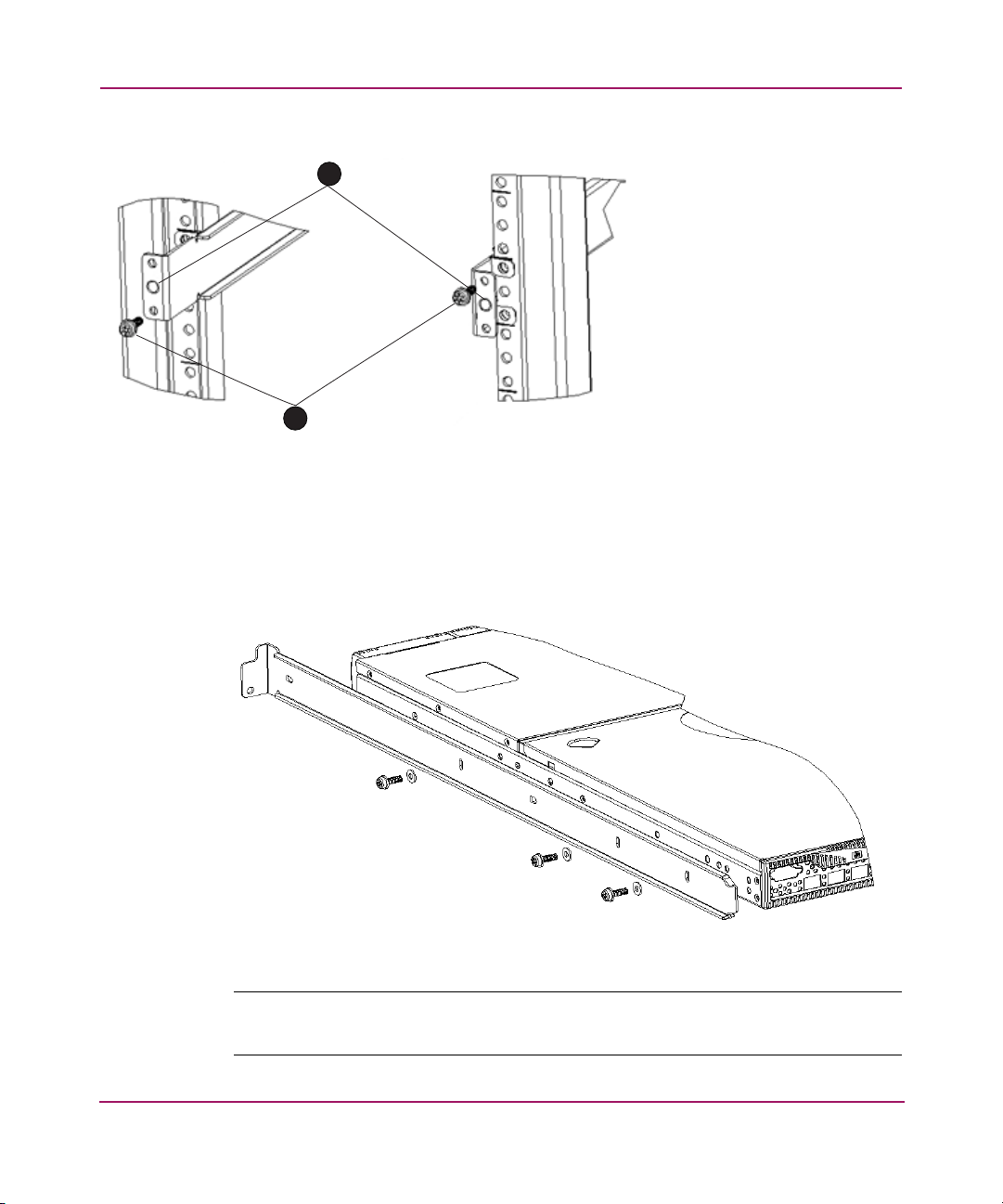
Installing and Configuring the Core Switch 2/64
1
2
SHR-2560A
1 Outer rail alignment pins 2 M5 torx screws
Figure 15: Assembling the outer rails (HP Rack)
7. Assemble the two inner rails (one on each side) to the switch using (6) #8-32
x 5/16 Phillips pan-head screws, and #8 flat washer as shown in Figure 16.
Figure 16: Assembling the inner rails
Note: Figure 16 shows installing the inner rails on a SAN Switch 2/16. The
procedure is similar for istalling the inner rails in the Core Switch 2/64.
65Core Switch 2/64 V4.1 Installation Guide
Page 66
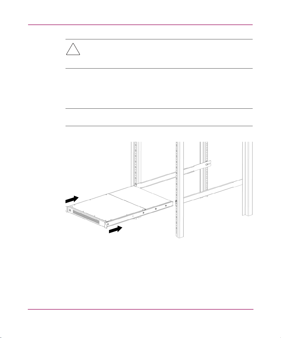
Installing and Configuring the Core Switch 2/64
Caution: Do not use any other screws other than the six that are provided.
Use of any longer lengths can cause damage to internal components of the
switch. Before tightening screws, make sure that the rails are centered to the
overall height of the switch.
8. Insert the switch with the attached inner rails into the outer rails.
9. Install the two remaining M5 Torx screws to complete the installation. See
Figure 17.
Note: Figure 17 shows installing the screws on a SAN Switch 2/16. The procedure is
similar for istalling the screws in the Core Switch 2/64.
SHR-2562A
Figure 17: Installing switch into the HP rack
10. See the next section Powering On for the First Time on page 67 for
instructions on applying power to the switch.
66 Core Switch 2/64 V4.1 Installation Guide
Page 67
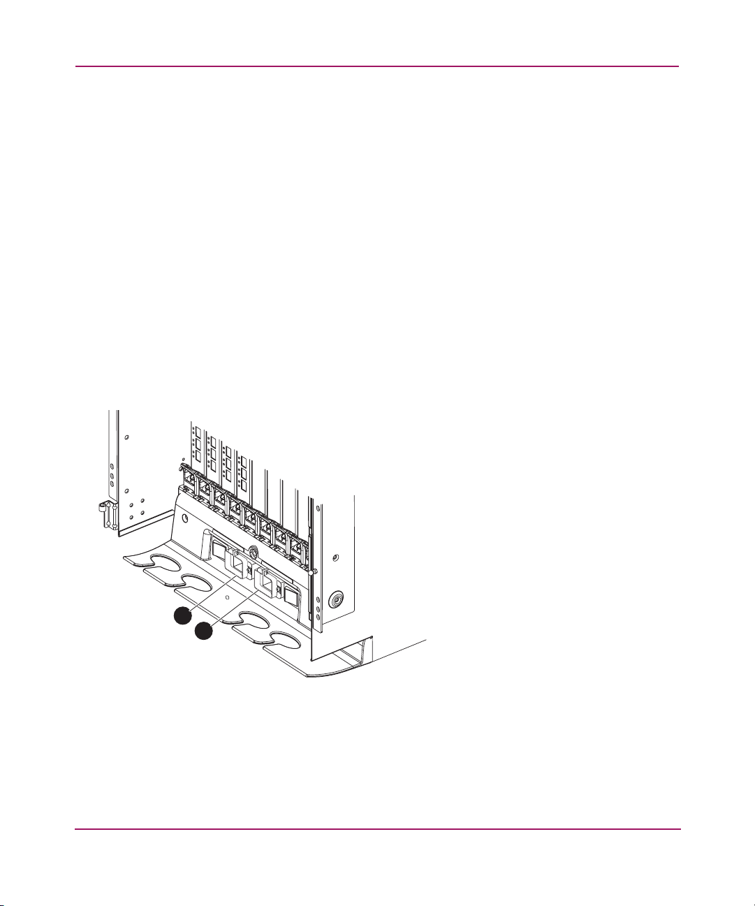
Powering On for the First Time
Use these steps to install the power cord retainers, and apply power to the Core
Switch 2/64.
Installing the Power Cord Retainers
HP provides two power cord retainers to hold the AC power cords in place.
Phillips screws (#4-40) are included. A #1 Phillips screwdriver is a required tool.
Use these steps to attach each power cord retainer onto the AC power inlets.
1. Orient each power retainer as shown in Figure 18.
2. Loosen the adjusting screws on either side of the power inlets to allow the
power cord to fit into the retainer.
3. Position the power cord retainer tabs under the two screws on either side of a
power connector on the chassis, see Figure 18. The power cords are designed
with right and left bends.
.
Installing and Configuring the Core Switch 2/64
1
2
SHR-2530A
Figure 18: Installing power cord retainers
1 Left power cord
retainer
2 Right power cord
retainer
67Core Switch 2/64 V4.1 Installation Guide
Page 68
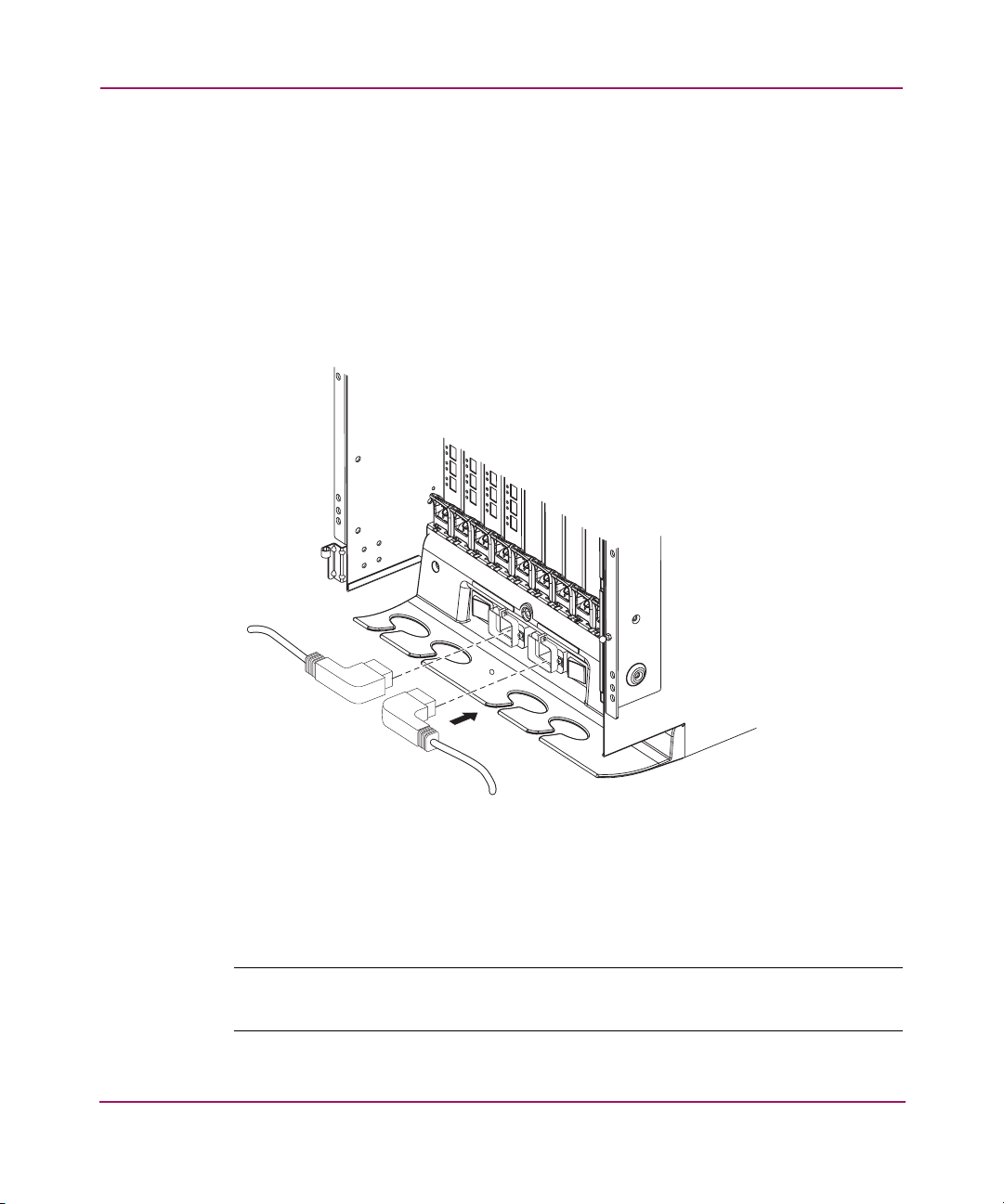
Installing and Configuring the Core Switch 2/64
4. Tighten both screws.
5. Repeat step 1 through step 4 for the second power cord retainer.
Connecting Power Cords
Use these steps to connect power to the Core Switch 2/64.
1. Connect the power cords to the power connectors on the Core Switch 2/64,
inserting them through the power cord retainers. The power cords are
designed with right and left bends to facilitate cord management.
SHR-2531A
Figure 19: Power cord connections
2. Connect the two AC power cords to a power source with voltage of 200 to
240 VAC, 50-60 Hz.
Note: Installing each power cord using two separate sources ensures power supply
redundancy.
68 Core Switch 2/64 V4.1 Installation Guide
Page 69

Installing and Configuring the Core Switch 2/64
3. Verify that the power cord has a minimum service loop of 6 inches available
at the connection to the switch, and is routed so that it is not exposed to stress.
4. Flip both green AC power switches to 1. The AC power switch LEDs light
green.
Note: Powering off the switch triggers a system reset. When power is restored, all
devices are returned to the initial state, and the switch runs POST.
5. To turn power off, flip both AC power switches to 0.
Caution: Allow the Core Switch 2/64 to run for a minimum of 10 minutes
after powering on, before powering off again.
The switch automatically runs POST by default each time it is powered on.
POST takes a minimum of three minutes, and is complete when indicator light
activity returns to a normal state.
Running POST
Each time you power on or reset a switch, the switch automatically performs a
system check called POST. The POST cycle takes approximately three minutes to
complete. The following occurs during POST:
■ Preliminary POST diagnostics
■ Operating system initializes
■ Hardware initializes
■ Internal connections and circuitry diagnostics
In addition, the following switch initialization processes run:
■ The switch obtains a domain ID and assigns port addresses
■ Unicast routing tables created
■ Normal port operation enabled
■ Universal port configuration
■ Links initialize
69Core Switch 2/64 V4.1 Installation Guide
Page 70

Installing and Configuring the Core Switch 2/64
Checking POST Results
To verify that POST has completed, and the switch is operating normally:
■ Check that all LEDs have returned to a normal state after POST completes
(refer to Chapter 3, Interpreting LED Activity, on page 101, for specific LED
patterns and their meanings).
If one or more LEDs do not return to a normal state, (and this is not due to the
switch beaconing), use the slotShow command to check port status.
■ Verify that the switch prompt displays when POST completes. If it does not
display, POST was not successfully completed. Contact your switch supplier
for support.
■ Review the system log. Any errors detected during POST are written to the
system log, which is accessible through the errShow command.
70 Core Switch 2/64 V4.1 Installation Guide
Page 71

Core Switch PID Format Summary
A Core PID format is one of several addressing formats used in Fibre Channel.
The parameter is used by the routing and zoning services in Fibre Channel fabrics
to identify ports in the network.
The PID format is analogous to specifying the physical switch and port a device is
attached to in data networks. It is not analogous to an IP address. PIDs are
assigned by a Fibre Channel switch when a device logs into the fabric.
The following example shows a sample PID:
011F00
Many scenarios cause a device to receive a new PID. For example, unplugging the
device from one port and plugging it into a different port will cause this. (This
might happen when cabling around a bad port, or when moving equipment
around.) Another example is changing the domain ID of a switch, which might be
necessary when merging fabrics, or changing compatibility mode settings.
Note: All switches running Fabric OS version 4.0.x or higher are shipped with the
Core Switch PID Format enabled, so it is not necessary to change the Core Switch PID
format on these switches. For example, the HP StorageWorks SAN Switch 2/32 and
HP StorageWorks Core Switch 2/64 always use Core Switch PID format 1. This
parameter is always 1 and cannot be changed.
Installing and Configuring the Core Switch 2/64
Important Information on Checking the Core Switch PID Format
You must update the Core Switch PID Format when upgrading an existing SAN
to support larger port-count switches. When a switch with more than 16 ports is
introduced into an existing fabric, this parameter needs to be set on all switches in
the fabric.
For example, all SAN Switch 2/32 units ship with the Core Switch PID format set
to 1. Before connecting to the SAN, you must verify that the Core Switch PID
formats of all switches already running in the SAN are also set to 1.
71Core Switch 2/64 V4.1 Installation Guide
Page 72

Installing and Configuring the Core Switch 2/64
Note: If the Core PID format is set to 0 in switches already running in the SAN, you
must follow the procedures in Appendix B, “Updating the Core Switch PID Format” to
change the parameter to 1. If the Core Switch PID format is not changed to 1 to match
the SAN Switch 2/32’s value, then the switches residing in the SAN will fail to
communicate with one another.
For detailed recommendations and instructions on updating the Core Switch PID,
please refer to Appendix A, Extensive Information on the PID Format, on
page 184.
72 Core Switch 2/64 V4.1 Installation Guide
Page 73

Configuration Overview
The Core Switch 2/64 can contain up to two logical switches, each with its own
configuration: one logical switch for any 16-port cards in slots 1-4, and one
logical switch for any 16-port cards in slots 7-10.
The configuration information for both logical switches is stored in the WWN
card and in the CP cards’ flash memory. The configuration settings are
automatically mirrored to the standby CP card. In this way, the most current
configuration is available even if the active CP card fails.
In addition, you can back up the configuration up by uploading the settings to a
workstation using the configUpload command, and can be downloaded to the
active CP card using the configDownload command.
Note: A routine backup of the configuration is recommended, to ensure the current
configuration is available if needed. IF the fabric will include switches running version
of Fabric OS that are earlier than 4.1, those switches must have the Core PID set to
“1” in order to join a fabric with switches running Fabric OS v4.0 or later. For
information on setting the Core PID, refer to the
Procedures Version 3.1.x/4.1.x User Guide
Installing and Configuring the Core Switch 2/64
HP StorageWorks Fabric OS
.
The Core Switch 2/64 configuration can be modified only through a login session
to the active CP card. The switch supports up to two simultaneous telnet sessions
(with administrative privileges).
Note: For fabric OS v4.1, different logins are provided for each logical switch.
Logical Switch 0 has logins User0, Admin0, Factory0, and Root0. Logical Switch 1
has logins User1, Admin1, Factory1, and Root1. For versions earlier than v4.1, the
same administrative login account applies to both logical switches. If the password is
changed on switch 0, it is automatically changed on switch 1.
73Core Switch 2/64 V4.1 Installation Guide
Page 74

Installing and Configuring the Core Switch 2/64
Preset Configuration Settings
Caution: Resetting a logical IP address while the switch is running in the
fabric may cause Web Tools, Fabric Watch, SNMP, and other applications to
terminate.
The Core Switch 2/64 ships with the following factory installed settings:
■ General system parameters (modifiable through the configure
command).
■ WWNs for both logical switches: The two WWNs are not modifiable; both
are pre-configured and are usually based on the chassis serial number.
■ Domain ID: The default domain ID for both logical switches is 1.
■ One domain ID for any 16-port cards in slots 1-4, and one for any 16-port
cards in slots 7-10 (domain IDs can be modified through the configure
command)
■ A native IP address, host name, subnet mask, and gateway address for both
CP card slots (modifiable through the ipAddrSet command).
■ Logical IP addresses: A logical IP address and subnet mask for both logical
switches (modifiable through the ipAddrSet command).
■ Switch names for both logical switches (modifiable through the
switchname command).
■ Switch status policies (modifiable through the switchstatusploicyset
command).
■ Core PID setting (modifiable through the configure command).
74 Core Switch 2/64 V4.1 Installation Guide
Page 75

Installing and Configuring the Core Switch 2/64
Configuring Core Switch 2/64 Network Addressing
You must configure the Core Switch 2/64 to operate correctly within the network
and fabric. The following sections describe network addressing procedures.
Items Required
The following items are required to configure and connect the Core Switch 2/64:
■ Core Switch 2/64 powered on but not connected to a network or fabric
■ Workstation computer with a terminal emulator application (such as
HyperTerminal)
■ Serial cable provided with the switch
■ Ethernet cable
■ SFP transceivers and cables, as required
■ Two IP addresses for use as the “native” IP addresses assigned to the CP slots,
with the corresponding native host names, subnet masks, and gateway
addresses.
The default native IP addresses and host names are as follows:
— 10.77.77.75 CP0 (the CP card in slot 5 at the time of configuration)
— 10.77.77.74 CP1 (the CP card in slot 6 at the time of configuration)
■ Two IP addresses for use as the “logical” IP addresses of the switch, with the
corresponding subnet masks. These IP addresses correspond to switch 0,
which contains any 16-port cards in slots 1-4, and switch 1, which contains
any16-port cards in slots 7-10.
■ The default logical IP addresses are as follows:
— 10.77.77.77 sw0
— 10.77.77.76 sw1
■ Two switch names, if you do not use the default switch names.
Switch names can be up to 15 characters long, can include alpha, numeric,
and underscore characters, and must begin with an alpha character. The
default switch name for the logical switches are sw0 for the switch containing
the 16-port cards in slots 1-4, and sw1 for the switch containing 16-port cards
in slots 7-10.
75Core Switch 2/64 V4.1 Installation Guide
Page 76
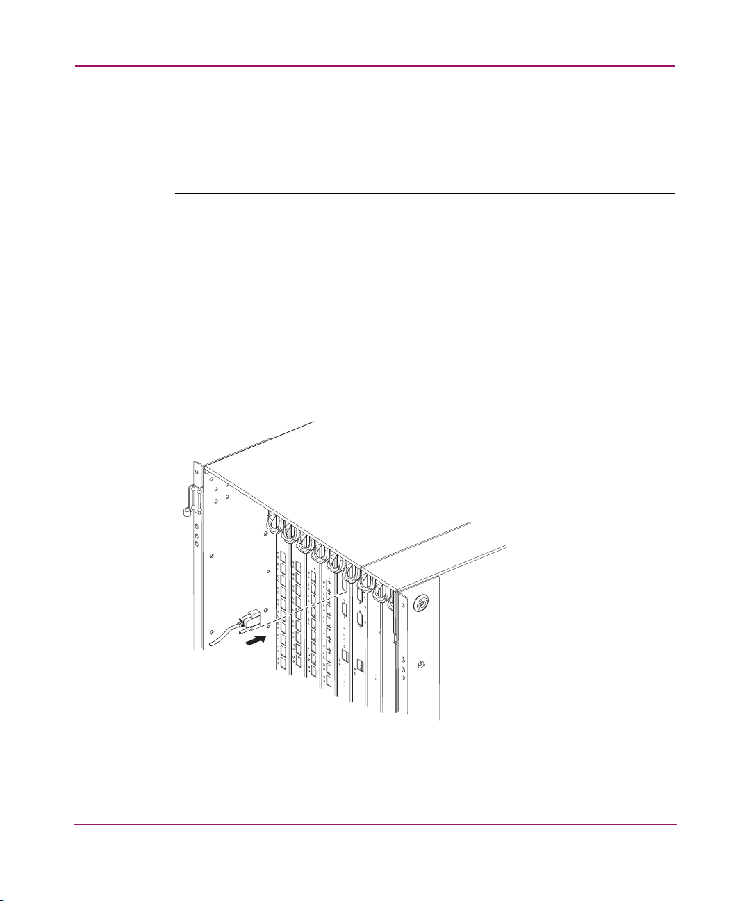
Installing and Configuring the Core Switch 2/64
Setting Network Addresses via a Network Connection
Use these steps to set Core Switch 2/64 network addresses.
1. Verify that switch power is on, and POST is complete.
Note: Post is complete when all power LED indicators on the 16-port cards and CP
cards display a steady green light. For a description of LED patterns, see Chapter 3,
Operating the Core Switch 2/64.
2. Log onto the CP card installed in slot 5 by establishing a serial connection to a
workstation running a terminal emulator application (such as HyperTerminal
on Windows or TERM in a Unix environment).
a. Disable any serial communication programs running on the workstation
(such as synchronization programs for a PDA).
b. Remove the shipping cap from the terminal serial port on the CP card in
slot 5, and insert the serial cable, see Figure 20.
SHR-2515A
Figure 20: CP card serial port location
76 Core Switch 2/64 V4.1 Installation Guide
Page 77
Installing and Configuring the Core Switch 2/64
c. Connect the other end of the serial cable to a serial port on the
workstation.
If necessary, the adapter on the serial cable can be removed to allow for
an RJ45 serial connection.
d. Open the terminal emulator application and configure as described in
these steps.
— For Windows operating systems, enter the following parameters:
Parameter Value
Bits per second 9600
Databits 8
Parity None
Stop bits 1
Flow control None
— For most UNIX systems, enter the following string at the prompt:
tip /dev/ttyb -9600
e. When the terminal emulator application stops reporting information, press
Enter to reach the CP0 Console Login prompt.
f. Enter the administrative logon information. The default administrative
logon is admin and the default password is password.
g. Enter 0 at the login prompt.
Note: At the initial login the user is prompted to enter new Admin and User
passwords. The same administrative account applies to both logical switches. If the
password is changed on switch 0, it is automatically changed on switch 1.
h. Modify passwords if desired. Passwords must be a total of 8 to 40
characters long, and should include a combination of numbers and upper
case and lower case letters.
Note: Press CTRL-C to skip modifying the password.
77Core Switch 2/64 V4.1 Installation Guide
Page 78

Installing and Configuring the Core Switch 2/64
3. Determine which CP card is active by entering the following command:
haShow
This command provides the following information:
switch:admin> haShow
Local CP (Slot 5, CP0): Active
Remote CP (Slot 6, CP1): Standby, Healthy
HA Enabled, Heartbeat Up, HA State not in sync
4. Configure the IP addresses for both CP cards, as follows.
Note: Configuration changes can only be made through a session with the active CP
card; although you can assign IP addresses to either CP card from a session with the
active CP card.
a. If the CP card in slot 5 is not the active CP card, disconnect the serial
cable from the CP card, connect it to the CP card in slot 6, and log on as
Admin.
b. Enter the ipAddrSet command at the prompt, entering 2 for the CP
card in slot 5, and 3 for the active CP card in slot 6. For example:
ipAddrSet 2
c. Follow the onscreen prompts, and enter the appropriate information, as
shown in the following example (the default information for the CP card
in slot 5 is shown):
switch:admin> haShow
Ethernet IP Address [10.77.77.75]:
Ethernet Subnetmask [255.9.9.9]:
Host Name [CPQ]:
Gateway Address [0.0.0.0]:
Note: The host name is the native name assigned to the CP card. The same gateway
address must be used for both CP cards (these gateway addresses are referenced for
the logical IP addresses).
78 Core Switch 2/64 V4.1 Installation Guide
Page 79

Installing and Configuring the Core Switch 2/64
The native IP address of the active CP card is updated immediately. The
native IP address of the standby CP card is updated at the next reboot.
d. Repeat steps 4a through 4c for the remaining CP card.
5. Configure the two logical IP addresses, as follows.
Caution: Resetting a logical IP address while the switch has active IP traffic
such as Web Tools, Fabric Watch, SNMP, and other applications, may cause
them to terminate.
a. To configure the first logical IP address, enter the following command at
the prompt:
ipAddrSet 0
b. Follow the onscreen prompts, and enter the appropriate addressing
information:
Ethernet IP Address [10.77.77.77]:
Ethernet Subnetmask [0.0.0.0]:
Fibre Channel IP Address [none]:
Fibre Channel Subnet Mask [none]:
The logical IP address is updated immediately.
c. To configure the second logical IP address, enter the following command
at the prompt:
ipAddrSet 1
d. Follow the onscreen prompts, and enter the appropriate addressing
information, as described in step 5b.
e. Type reboot at the prompt to reboot the CP card.
Note: The terminal serial port can be used to monitor error messages through a serial
connection. HP does not recommend using it as a command interface during normal
operations because it only modifies one switch at a time (switch 0 by default).
f. When complete, remove the serial cable.
g. Replace the serial port’s protective cap.
79Core Switch 2/64 V4.1 Installation Guide
Page 80

Installing and Configuring the Core Switch 2/64
Connecting the Core Switch 2/64 to the LAN
Use these steps to connect the active CP card to an Ethernet connection.
1. Remove the shipping plug from the Ethernet port on the active CP card.
2. Insert one end of an Ethernet cable into the CP card’s Ethernet port.
3. Connect the remaining end to an Ethernet 10/100 Base-T LAN.
Note: The switch can now be accessed by remote connection using any of the
available management tools, such as telnet or Web Tools. Ensure that the switch is not
modified from other connections during the rest of this procedure. You can complete
the remaining steps in this procedure through either the serial session or a telnet
session.
4. Log on to either of the logical switches by telnet, using the administrative
logon. (The default administrative logon name is admin and the default
password is password.)
5. Customize the switch names for the logical switches, as follows.
Note: HP recommends using the default switch names if possible. Changing the switch
name causes a domain address RSCN format to be issued.
a. Enter the command switchName with the new name in quotes as
follows (sw10 is an example name):
switchName "sw10"
b. Record the new switch name for future reference.
c. Customize the switch name for the other logical switch:
— Logout of the CP session
— Connect the serial cable to the other CP card
— Log in as Admin
— Repeat steps 5a through 5b for the other logical switch.
80 Core Switch 2/64 V4.1 Installation Guide
Page 81

Modifying Domain IDs
Use these steps to modify the domain IDs, if desired. This is an optional
procedure.
1. To view a list of the current domain IDs, open a a telnet session, and type
fabricShow.
Note: The default domain ID for both switches is “1”. To prevent a domain ID conflict,
make the domain IDs unique before connecting the switches to the fabric.
2. Enter the switchDisable command to disable the switch.
3. Enter the
4. Enter Y after the Fabric parameters prompt.
5. Enter a unique domain ID.
Domain: (1..239) [1] 3
6. Follow the remaining onscreen prompts, (or press CTRL+D to accept the
default settings and exit).
7. Enter the switchEnable command to enable the switch.
Installing and Configuring the Core Switch 2/64
configure command.
8. Before connecting the Core Switch 2/64 to the fabric, verify that all the
switches in the fabric use the correct PID settings. If the fabric will include
switches running versions of Fabric OS that are earlier than 4.1, those
switches must have the Core PID set to 1 in order to join a fabric with
switches running Fabric OS v4.0 or later. For information on setting the Core
PID, refer to the HP StorageWorks Fabric OS Procedures Version 3.1.x/4.1.x
User Guide.
Specify Custom Status Policies
Use these steps to specify custom status policies, if desired. This is an optional
procedure.
1. To access the status policy, enter the following command at the prompt:
switchStatusPolicySet
2. Follow the onscreen prompts to specify the status policies.
3. To completely deactivate the alarm for a particular condition, enter 0 at the
prompt for that condition.
81Core Switch 2/64 V4.1 Installation Guide
Page 82

Installing and Configuring the Core Switch 2/64
Connecting SFPs
Use these steps to connect SFPs (Small Form Factor Pluggable) to the Fibre
Channel ports as required. Purchase SFPs separately. For purchasing information,
refer to Table 3 in the section Optional Hardware Kits in Chapter 1, on page 30.
Note: The ports are color-coded to indicate which ones can be used in the same
trunking groups: four ports marked with black solid ovals alternate with four ports
marked with oval outlines.
Note: The ports and cables used in trunking groups must meet specific requirements.
Caution: Do not route cables in front of the exhaust vent (located at the top of
the port side of the chassis).
1. Position one of the SFP transceivers so that the key is oriented correctly to the
port, and insert the transceiver into the port until it is firmly seated and the
latching mechanism clicks. See Figure 21.
82 Core Switch 2/64 V4.1 Installation Guide
Page 83
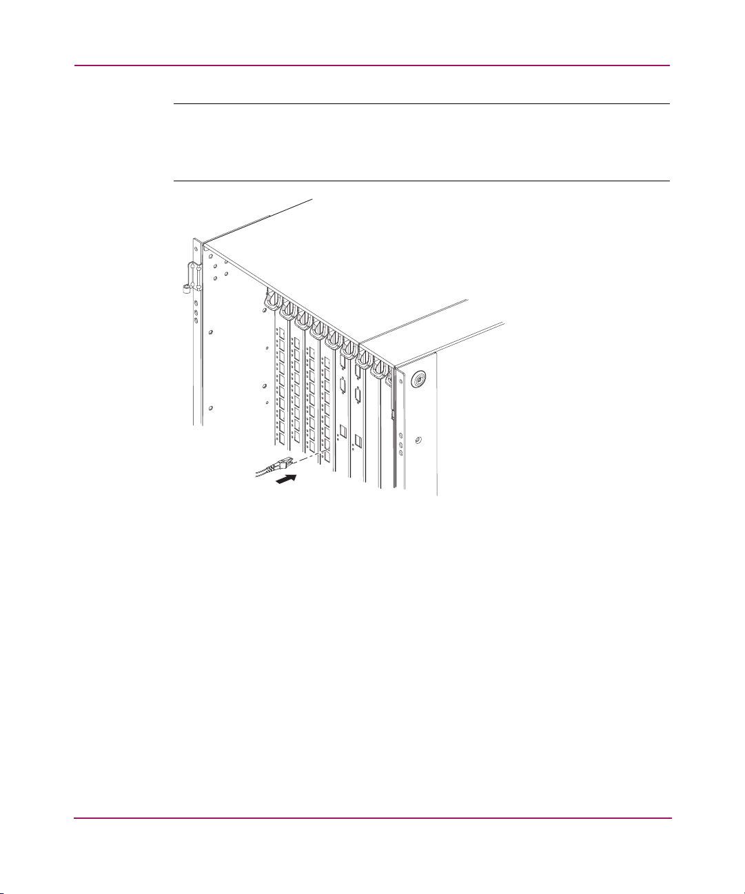
Installing and Configuring the Core Switch 2/64
Note: Transceivers are keyed so that they can only be inserted with the correct
orientation. If the transceiver does not slide in easily, ensure it is correctly oriented. For
instructions that are specific to the transceiver model, refer to the transceiver
manufacturer’s documentation.
SHR-2517A
Figure 21: Connecting of a fiber cable
2. Position a cable so that the key (the ridge on one side of the cable connector)
aligns with the slot in the transceiver, then insert the cable into the transceiver
until the latching mechanism clicks.
Cables are keyed so that they can only be inserted with the correct orientation.
If a cable does not slide in easily, ensure it is correctly oriented.
3. Repeat step 1 and step 2 for the remaining ports.
4. Organize the cables as required.
5. Check port status. Enter the following command at the telnet prompt:
switchShow
This command provides detailed information about the switch.
83Core Switch 2/64 V4.1 Installation Guide
Page 84

Installing and Configuring the Core Switch 2/64
6. Check the fabric for ISLs, switch names, or other status by entering the
following command at the telnet prompt:
fabricShow
This command provides general information about the fabric.
7. After all zoning configurations and other changes are complete, back up the
configuration. Enter the following command at the telnet prompt:
configUpload
This command uploads the switch configuration to the server, so that it is
available for downloading to a replacement switch if necessary.
Note: A routine backup of the configuration is recommended.
84 Core Switch 2/64 V4.1 Installation Guide
Page 85

Installing and Configuring the Core Switch 2/64
Saving the System Configuration Files
Upload the switch configuration file for disaster recovery and keep it in a safe
place where it can be easily found. Backing up the configuration after the initial
configuration changes is strongly recommended. A routine backup of the
configuration is also recommended to ensure the current configuration is available
if needed.
Backing up the Switch Configuration Settings
Use File Transfer Protocol (FTP) on Windows or UNIX workstations to backup
the system configuration. The FTP server must be running before an upload can
occur.
1. Verify that the FTP service is running on the host workstation.
2. Log in to the switch as the admin user.
3. At the command line enter the following command:
configUpload “
The hostIPaddr is the IP address of the host computer, user is the User ID for
this computer, path_filename is the path location of the configuration file, and
password is the password for the user ID specified.
If you only enter configUpload, the system prompts you for each
parameter, as shown in the following example:
switch:admin> configupload
Server Name or IP Address [host]: 123.45.678.901
User Name [user]: kelev
File Name [config.txt]: switch1
Protocol (RSHD or FTP) [rshd]: ftp
Password:
upload complete
hostIPaddr
”, “
user
”, “
path_filename
”,”
password
”
85Core Switch 2/64 V4.1 Installation Guide
Page 86

Installing and Configuring the Core Switch 2/64
Restoring the System Configuration Settings
To restore the system configuration settings from a backup:
1. Verify that the FTP service is running on the host workstation.
2. Log in to the switch as the admin user.
3. Shut down the switch by entering the following command:
switchDisable
4. At the command line enter the following command:
configDownload “
The hostIPaddr is the IP address of the host computer, user is the User ID for
this computer, path_filename is the path location of the configuration file, and
password is the password for the user ID specified.
Note: The password operand is only required if you are using FTP.
5. Reboot the switch by entering the following command:
fastBoot
hostIPaddr
”, “
user
”, “
path_filename
”,”
password
”
86 Core Switch 2/64 V4.1 Installation Guide
Page 87

Setting Up Speed Negotiation
There are two methods for configuring the ports on the HP StorageWorks Core
Switch 2/64. The port can be set to auto-sensing mode, which allows the port to
automatically be configured to the highest speed. Ports can also be set to a fixed
speed of either 1 or 2 Gbps.
To display the configuration settings of the ports on a switch, use the
portCfgShow command. The port speed is displayed as 1G (fixed speed of 1
Gbps), 2G (fixed speed of 2 Gbps), or AN (auto negotiate). To set the speed level
for all the ports on a switch, use the telnet command switchCfgSpeed. To set
the speed level for a single port, use the portCfgSpeed command.
Depending on your environment, you may need to force a port to use a specific
speed level because auto negotiation may not be supported by the device. Check
the configuration information for your network components for specific
requirements.
Installing and Configuring the Core Switch 2/64
87Core Switch 2/64 V4.1 Installation Guide
Page 88

Installing and Configuring the Core Switch 2/64
88 Core Switch 2/64 V4.1 Installation Guide
Page 89

Operating the Core Switch 2/64
This chapter describes how to use the Core Switch 2/64, and includes the
following topics:
■ Powering the Core Switch 2/64 On and Off, page 90
■ Operating Information for System Components, page 91
■ Reviewing Default Configuration Settings, page 99
■ Interpreting LED Activity, page 101
■ System Components, page 102
■ Interpreting POST Results, page 116
■ Performing Diagnostic Tests, page 117
■ Environmental Status and Maintenance Commands, page 118
3
89Core Switch 2/64 V4.1 Installation Guide
Page 90

Operating the Core Switch 2/64
Powering the Core Switch 2/64 On and Off
Note: To provide power to the switch for the first time, see the section Powering On
for the First Time on page 67 in Chapter 2.
To power on the Core Switch 2/64:
1. Verify both power cords are connected to the AC power connectors on the
front of the chassis.
2. Flip both green AC power switches to 1. The green AC power switches
illuminate.
Caution: Allow the Core Switch 2/64 to run for a minimum of 10 minutes
after powering on to ensure the switch has fully booted before powering off
again.
To power off the Core Switch 2/64:
1. Flip both AC power switches to 0.
2. To remove all sources of power from the switch, disconnect both cables from
the power source.
Note: Removing all power from the switch triggers a system reset. When power is
restored, all devices are returned to the initial state and the switch runs POST.
90 Core Switch 2/64 V4.1 Installation Guide
Page 91

Operating the Core Switch 2/64
Operating Information for System Components
The Core Switch 2/64 includes two logical switches: one for any port cards in
slots 1-4, and one for any port cards in slots 7-10. The port cards can be installed
in any combination of slots 1-4 (switch 0) and 7-10 (switch 1).
The active CP card controls both logical switches.
Port Cards
Caution: Wear a grounded ESD strap when handling a port card. A
grounding connection is available on the chassis above the power
connectors.
To ensure correct cooling of the chassis and provide protection from dust,
install a filler panel in any slots that do not contain a port card.
Disassembling any part of a port card voids the part warranty and regulatory
certifications. There are no user-serviceable parts inside the port card.
Each port card provides 16 auto-sensing Fibre Channel ports, capable of
auto-sensing data transmission speeds of 1 and 2 Gbps.
The ports on each of the port cards are color-coded to indicate which ports can be
used in the same ISL Trunking group: four ports marked with black solid ovals
alternate with four ports marked with oval outlines. An illustration of the Port
Card is provided in Figure 22 on page 103.
Note: ISL Trunking is a Fabric OS feature that enables distribution of traffic over the
combined bandwidth of up to four ISLs between two directly adjacent switches, while
preserving in-order delivery. For more information, refer to the
Trunking Version 3.1.x/4.1.x User Guide
.
HP StorageWorks ISL
The switch can continue to operate while a port card is being replaced, but any
devices connected to the port card must be disconnected. To ensure correct air
circulation inside the switch and provide protection from dust, filler panels can be
ordered for any empty slots.
91Core Switch 2/64 V4.1 Installation Guide
Page 92

Operating the Core Switch 2/64
To determine the status of a port card:
1. Check the LED indicators on the port card. For information about how to
interpret the LED patterns, refer to Table 9 on page 104.
2. Check port card status using the slotshow command.
For additional information about this command, refer to the HP StorageWorks
Fabric OS Version 3.1.x/4.1.x Reference Guide.
Control Processor Cards
Caution: Wear a grounded ESD strap when handling a CP card. A
grounding connection is available on the chassis above the power
connectors.
To ensure correct cooling of the chassis and provide protection from dust,
install a filler panel in any slots that do not contain a CP card.
Disassembling any part of a CP card voids the part warranty and regulatory
certifications. There are no user-serviceable parts inside the CP card.
About the CP Card
High availability is provided through redundant CP cards. One CP card acts as the
active CP card, actively controlling the Core Switch 2/64. The other acts as
standby in case rapid failover is required. Failover occurs as soon as the active CP
card is detected to be faulty or uninstalled. If the active CP card fails or is
uninstalled, the standby CP card automatically becomes the new active CP card.
The configuration is mirrored to the standby CP, so that if failover occurs, the
current configuration is still available.
Information about both CP cards, including which card is active, is available
through the hashow command. For information about commands and whether
they can be entered through the active or standby CP card, refer to the HP
StorageWorks Fabric OS Version 3.1.x/4.1.x Reference Guide.
The switch can continue to operate while a CP card is being replaced. To ensure
correct air circulation inside the switch and protection from dust, filler panels can
be ordered for any empty slots. An illustration of the CP Card is provided in
Figure 23 on page 107.
92 Core Switch 2/64 V4.1 Installation Guide
Page 93

Available Ports
Each CP card provides the following ports:
■ Modem serial port (labeled RS-232)—The modem serial port has an RS-232
connector wired as a DTE device, and is designed to connect to a DCE device,
such as a modem.
■ Terminal serial port (also known as a console port; labeled 10101)—The
terminal serial port has an RS-232 signal subset connector that can be used to
connect to a PC serial port or dumb terminal.
■ Ethernet port—The ethernet port has an RJ-45 connector, and is capable of
speeds of 10/100 Mbps.
Modem Connection
A separate modem can be connected to each modem serial port, and then
connected to the same or separate telephone lines for redundancy. For modem
installation instructions, see Appendix D, Setting Up and Configuring Modems.
Note: The Core Switch 2/64 only detects modems during power on or reboot. If a
modem is connected to an operating switch, the Core Switch 2/64 must be rebooted
in order to detect the modem.
Operating the Core Switch 2/64
Services Controlled by the CP Card
The active CP card controls the following services:
■ System initialization
■ High availability and switch drivers
■ Name server
■ SNMP
■ Fabric OS
■ Extended Fabrics
■ Fabric Watch
■ Remote Switch
■ Web Tools
■ Zoning
■ Secure Fabric OS
■ Performance Monitoring
93Core Switch 2/64 V4.1 Installation Guide
Page 94

Operating the Core Switch 2/64
Determining the Status of the CP Card
To determine the status of a CP card:
■ Check the LED indicators on the CP card. For information about how to
interpret the LED patterns, refer to Table 10 on page 108.
■ Check CP card status using the slotshow and hashow commands.For
additional information about these commands, refer to the HP StorageWorks
Fabric OS Version 3.1.x/4.1.x Reference Guide.
Power Supplies
The Core Switch 2/64 uses up to four power supplies, with a minimum of two
required to power a completely loaded chassis. The left power connector provides
power to the power supplies in slots #1 and #3 (color-coded blue), and the right
power connector provides power to the power supplies in slots #2 and #4
(color-coded yellow).
The Core Switch 2/64 can continue operating while a power supply is replaced if
at least one power supply continues operating for every four port cards installed.
A minimum of two power supplies are recommended.
Caution: To protect against AC failure, a minimum of one power supply in
slot #1 or slot #3 and one in slot #2 or #4 is recommended. If only two power
supplies are installed and they are both installed in slots corresponding to the
same power cable, an accidental unplugging of that power cable will power
down the entire chassis. Color coding indicates which AC switches and
connectors correspond to which power supplies.
Before replacing a power supply, determine whether adequate power to keep
the chassis operating will be available throughout the replacement. If not, shut
down both switches before continuing (see Replacing the Power Supply or
Filler Panel on page 149). If adequate power is abruptly lost such as through
removal of a power supply, the entire switch is powered down; the power off
order designated by powerOffListSet is not followed.
Disassembling any part of the power supply voids the part warranty and
regulatory certifications. There are no user-serviceable parts inside the power
supply.
94 Core Switch 2/64 V4.1 Installation Guide
Page 95

To determine the status of a power supply:
1. Check the LED indicators on the power supply. For information about how to
interpret the LED patterns, refer to Table 11 on page 111.
2. Check power supply status using the psshow command. The power supply
status displays OK, absent, faulty. If a power supply is absent or faulty,
contact the switch supplier to order replacement parts, as necessary. For
additional information about the psshow command, refer to the HP
StorageWorks Fabric OS Version 3.1.x/4.1.x Reference Guide.
AC Power Input Connectors and AC Power Switches
The Core Switch 2/64 has two AC power input connectors, each with a green AC
rocker switch. The left power input connector provides power to the power
supplies in slots #1 and #3, and the right power input connector provides power to
the power supplies in slots #2 and #4. The power input connectors and their
associated power supplies are color-coded.
Caution: Unplugging a single power cable can power down the entire
switch, depending on which power supply slots contain power supplies.
Operating the Core Switch 2/64
Two detachable power cords are provided with the system and are customized for
the country in which the system is installed. The AC power switches light up
green when on.
Blower Assemblies
The switch is cooled by three blower assemblies located in the back of the chassis.
The air enters through the vents in the blower assembly side of the chassis and
exits from the top vent on the port side of the chassis. The chassis requires a
minimum air flow of 350 cubic feet per minute (595 cubic meters per hour).
The blower assemblies are hot-swappable, although two blower assemblies must
remain operating at all times. If more than one blower assembly must be removed
at the same time, power off the Core Switch 2/64 to prevent overheating.
95Core Switch 2/64 V4.1 Installation Guide
Page 96

Operating the Core Switch 2/64
WARNING: The Core Switch 2/64 requires a minimum of two functioning
blower assemblies during operation. To ensure continuous adequate cooling,
maintain three operating blower assemblies at all times except for the brief
period when replacing a blower assembly.
The Core Switch 2/64 port cards automatically shut down if the internal
temperature range is exceeded.
Caution: Disassembling any part of the blower assembly voids the part
warranty and regulatory certifications. There are no user-serviceable parts
inside the blower assembly.
To determine the status of a blower assembly:
1. Check the LED indicators on the blower assembly. For information about
how to interpret the LED patterns, refer to Table 12 on page 113.
2. Check the blower assembly status by entering the fanshow command. The
status for each blower assembly displays OK, absent, or faulty. If any of the
blower assemblies are absent or faulty, contact the switch supplier to order
replacement parts, as necessary. For additional information about the
fanshow command, refer to the HP StorageWorks Fabric OS Version
3.1.x/4.1.x Reference Guide.
WWN Card and Bezel
The WWN card and bezel are located at the top of the blower assembly side of the
chassis. The WWN card and bezel provide LEDs for monitoring the switch from
the blower assembly side of the chassis. The WWN card also stores the following
information:
■ The chassis serial number (used when installing software licenses)
■ The two IP addresses assigned to the CP card slots
■ Information for the two logical switches in the Core Switch 2/64:
— The logical switch names
— The logical IP addresses
— The logical WWNs
96 Core Switch 2/64 V4.1 Installation Guide
Page 97

Operating the Core Switch 2/64
The bezel protects the card and identifies each of the LEDs on the WWN card.
Together, the WWN card and bezel assembly provide a consolidated view of the
LEDs for the two CP cards, eight port cards, and four power supplies. If a slot
contains a filler panel, the corresponding LEDs on the WWN card are not
illuminated.
Note: There are two possible versions of the WWN card; one is attached to the
chassis by screws, and the other version is held on by the pressure of the bezel against
a pad on the card face.
Caution: If the WWN card fails, follow the instructions provided with the
replacement card. Wear a grounded ESD strap when handling the card (a
grounding connection is available on the chassis above the power
connectors). Do not reboot the switch while the WWN card is uninstalled, as
this can cause the switch to boot incorrectly.
97Core Switch 2/64 V4.1 Installation Guide
Page 98

Operating the Core Switch 2/64
Managing Cables
Two items are provided to assist with cable management:
■ Cable Management Tray —The Cable Management Tray is attached to the
bottom of the chassis, and can be used to route the power cables and other
cables down below the chassis or out the sides of the chassis.
■ Cable Guides—A set of 16 cable guides are provided with the Core Switch
2/64, and can be used to organize the port cables into logical groups, such as
according to port quads (sets of four neighboring ports). The cable guides are
free-floating and do not attach to the chassis.
The cable guides serve to keep the cables evenly spaced and to hold them
away from the port cards to make card replacement easier and to prevent the
cables from bending to less than the minimum bend radius.
Caution: Do not route the cables in front of the air exhaust vent, which is
located at the top of the port side of the chassis.
The minimum bend radius for a 50-micron cable is 2 inches under full tensile
load, and 1.2 inches with no tensile load.
Tie wraps are not recommended for optical cables because they are easily
overtightened.
98 Core Switch 2/64 V4.1 Installation Guide
Page 99
Reviewing Default Configuration Settings
Read the following sections for default configuration settings.
Core Switch 2/64 Switch Settings
Table 6 lists Core Switch 2/64 default configuration settings.
Table 6: Core Switch 2/64 Default Parameters
Parameter Default
Switch Name for Logical Switch 0 Core Switch
Base IP Address for Logical Switch 0 10.77.77.77
Logical Switch 0 and 1 Subnet Mask 255.255.255.0
CP card 0 and 1 Subnet Mask 255.255.255.0
Ethernet Link Mode Auto
CLI Timeout 15 Minutes
Default Fabric Parameters
Operating the Core Switch 2/64
Table 7 lists Core Switch 2/64 default fabric parameters.
Table 7: Default Fabric Parameters
Parameter Default
Domain 1
BB_Credit 16
R_A_TOV 10,000
E_D_TOV 2000
WAN_TOV 0
MAX_HOPS 7
WAN_RTT_DLY_MAX 200
Data Field Size 2112
Sequence Level Switching 0
Disable Device Probing 1
Suppress Class F Traffic 0
99Core Switch 2/64 V4.1 Installation Guide
Page 100
Operating the Core Switch 2/64
Table 7: Default Fabric Parameters (Continued)
Parameter Default
SYNC IO Mode 0
VC Encoded Address Mode 0
Core Switch PID Format 1
Per-Frame Route Priorities 0
Long Distance Fabric 0
Default Virtual Channel Settings
Table 8 lists Core Switch 2/64 default virtual channel settings.
Table 8: Virtual Channel Settings
Parameter Default
VC Priority 2 2
VC Priority 3 2
VC Priority 4 2
VC Priority 5 2
VC Priority 6 3
VC Priority 7 3
100 Core Switch 2/64 V4.1 Installation Guide
 Loading...