

Page 1

hphpLaserJet 9055 mfp
LaserJet 9065 mfp
service manual
Page 2

Page 3

hp LaserJet 9055mfp (Q3631A)
hp LaserJet 9065mfp (Q3632A)
service manual
Page 4

Copyright Information
© 2003 Copyright Hewlett-Packard Development
Company, L.P.
Reproduction, adaptation or translation without
prior written permission is prohibited, except as
allowed under the copyright laws.
The information contained herein is subject to
change without notice.
The only warranties for HP products and services
are set forth in the express warranty statements
accompanying such products and services.
Nothing herein should be construed as
constituting an additional warranty. HP shall not be
liable for technical or editorial errors or omissions
contained herein.
Part number: Q3631-90908
Edition 1, 11/2003
Trademark Credits
Microsoft®, Windows®, and Windows NT® are
U.S. registered trademarks of Microsoft
Corporation.
Page 5

Contents
1 How to use this manual
Manual contents . . . . . . . . . . . . . . . . . . . . . . . . .2
Manual organization . . . . . . . . . . . . . . . . . . . . . .2
2 Safety
Safety and important warning items . . . . . . . . . .4
Important notices. . . . . . . . . . . . . . . . . . . . . 4
Description items for Warning, Caution,
and Note . . . . . . . . . . . . . . . . . . . . . . . 4
Safety warnings. . . . . . . . . . . . . . . . . . . . . . . . . . 5
Modifications not authorized by hp . . . . . . .5
Power supply. . . . . . . . . . . . . . . . . . . . . . . . 7
Installation requirements. . . . . . . . . . . . . .10
Measures to take in case of an accident. . 15
Conclusion . . . . . . . . . . . . . . . . . . . . . . . . 15
Regulatory statements . . . . . . . . . . . . . . . . . . .16
Safety information. . . . . . . . . . . . . . . . . . . . . . . 16
Safety circuits . . . . . . . . . . . . . . . . . . . . . .16
Overall protection circuit . . . . . . . . . . . . . . 16
Safety labels on the MFPs . . . . . . . . . . . . . . . . 19
Scanner section . . . . . . . . . . . . . . . . . . . .21
Laser/scanner assembly . . . . . . . . . . . . . .21
Rear cover. . . . . . . . . . . . . . . . . . . . . . . . . 21
3 MFP overview
Overview of system. . . . . . . . . . . . . . . . . . . . . .24
hp LaserJet 9055mfp/9065mfp product
specifications. . . . . . . . . . . . . . . . . . . . . . . 25
Type . . . . . . . . . . . . . . . . . . . . . . . . . . . . .25
Functions. . . . . . . . . . . . . . . . . . . . . . . . . . 25
Applicable copy paper. . . . . . . . . . . . . . . .26
Options . . . . . . . . . . . . . . . . . . . . . . . . . . . 26
Particulars of machine. . . . . . . . . . . . . . . . 26
Maintenance and life. . . . . . . . . . . . . . . . . 26
Environmental conditions . . . . . . . . . . . . . 26
Central cross-sectional view . . . . . . . . . . . . . . . 27
Drive system diagram . . . . . . . . . . . . . . . . . . . . 28
Fuser/web drive section . . . . . . . . . . . . . .28
Drum drive section . . . . . . . . . . . . . . . . . . 29
Developing drive section . . . . . . . . . . . . . . 29
Paper feed/vertical conveyance/tray
up drive sections . . . . . . . . . . . . . . . .30
Tray 1 paper feed/automatic duplex
unit (ADU) pre-registration
drive section . . . . . . . . . . . . . . . . . . . 31
Charging and transfer/separation wire
cleaning drive section . . . . . . . . . . . . 32
Automatic Duplex Unit (ADU)
conveyance drive section . . . . . . . . . 33
Paper exit drive section . . . . . . . . . . . . . . 34
Toner supply drive section . . . . . . . . . . . . 34
Optics drive section . . . . . . . . . . . . . . . . . 35
4 MFP unit explanation
External section . . . . . . . . . . . . . . . . . . . . . . . . 40
Composition . . . . . . . . . . . . . . . . . . . . . . . 40
Drive section. . . . . . . . . . . . . . . . . . . . . . . . . . . 41
Composition . . . . . . . . . . . . . . . . . . . . . . . 41
Mechanisms . . . . . . . . . . . . . . . . . . . . . . . 41
M2 (drum) control . . . . . . . . . . . . . . . . . . . 42
M4 (fuser) control . . . . . . . . . . . . . . . . . . . 42
Scanner section . . . . . . . . . . . . . . . . . . . . . . . . 44
Composition . . . . . . . . . . . . . . . . . . . . . . . 44
Mechanisms . . . . . . . . . . . . . . . . . . . . . . . 44
M11 (scanner) control. . . . . . . . . . . . . . . . 45
Exposure control . . . . . . . . . . . . . . . . . . . . 48
Original read control . . . . . . . . . . . . . . . . . 48
APS control. . . . . . . . . . . . . . . . . . . . . . . . 49
AE control . . . . . . . . . . . . . . . . . . . . . . . . . 51
Laser scanner unit . . . . . . . . . . . . . . . . . . . . . . 52
Composition . . . . . . . . . . . . . . . . . . . . . . . 52
Mechanisms . . . . . . . . . . . . . . . . . . . . . . . 52
M15 (polygon) control . . . . . . . . . . . . . . . . 53
Image write control . . . . . . . . . . . . . . . . . . 53
Drum unit . . . . . . . . . . . . . . . . . . . . . . . . . . . . . 56
Composition . . . . . . . . . . . . . . . . . . . . . . . 56
Mechanisms . . . . . . . . . . . . . . . . . . . . . . . 56
Separation claw control . . . . . . . . . . . . . . 57
Paper guide plate control . . . . . . . . . . . . . 57
Corona unit section. . . . . . . . . . . . . . . . . . . . . . 58
Composition . . . . . . . . . . . . . . . . . . . . . . . 58
Mechanisms . . . . . . . . . . . . . . . . . . . . . . . 58
Charging control . . . . . . . . . . . . . . . . . . . . 58
Transfer/separation control. . . . . . . . . . . . 59
Contents
ENWW iii
Page 6

M14 (charger cleaning) control . . . . . . . . . 60
M10 (transfer/separation cleaning)
control . . . . . . . . . . . . . . . . . . . . . . . .61
PCL/TSL control . . . . . . . . . . . . . . . . . . . . 62
Developing unit . . . . . . . . . . . . . . . . . . . . . . . . . 63
Composition . . . . . . . . . . . . . . . . . . . . . . .63
Mechanisms . . . . . . . . . . . . . . . . . . . . . . . 63
M3 (developing) control. . . . . . . . . . . . . . . 63
Developing bias control. . . . . . . . . . . . . . . 64
Dmax (maximum contrast) control . . . . . . 65
Gradation correction control . . . . . . . . . . . 67
Dot diameter correction control . . . . . . . . .68
Toner density control. . . . . . . . . . . . . . . . . 69
FM4 (developing suction) control . . . . . . . 69
Toner supply unit. . . . . . . . . . . . . . . . . . . . . . . .70
Composition . . . . . . . . . . . . . . . . . . . . . . .70
Mechanisms . . . . . . . . . . . . . . . . . . . . . . . 70
Toner level detection control . . . . . . . . . . . 71
M12 (toner supply) control . . . . . . . . . . . .72
Cleaning/toner recycle unit . . . . . . . . . . . . . . . . 73
Composition . . . . . . . . . . . . . . . . . . . . . . .73
Mechanisms . . . . . . . . . . . . . . . . . . . . . . . 73
Toner guide roller (TGR) control . . . . . . . . 74
Other control . . . . . . . . . . . . . . . . . . . . . . .74
Tray 2/3 paper feed unit . . . . . . . . . . . . . . . . . .75
Composition . . . . . . . . . . . . . . . . . . . . . . .75
Mechanisms . . . . . . . . . . . . . . . . . . . . . . . 75
First paper feed control . . . . . . . . . . . . . . . 77
Paper up drive control. . . . . . . . . . . . . . . .79
Paper size detection control . . . . . . . . . . . 80
No paper detection control . . . . . . . . . . . . 81
Tray 4 paper feed unit . . . . . . . . . . . . . . . . . . . . 82
Composition . . . . . . . . . . . . . . . . . . . . . . .82
Mechanisms . . . . . . . . . . . . . . . . . . . . . . . 82
First paper feed control . . . . . . . . . . . . . . . 84
Paper up drive control. . . . . . . . . . . . . . . .86
Paper size detection control . . . . . . . . . . . 87
No paper detection control . . . . . . . . . . . . 87
Tray 1 (bypass tray) . . . . . . . . . . . . . . . . . . . . . 89
Composition . . . . . . . . . . . . . . . . . . . . . . .89
Mechanisms . . . . . . . . . . . . . . . . . . . . . . . 89
First paper feed control . . . . . . . . . . . . . . . 90
Paper up/down control . . . . . . . . . . . . . . .90
Paper size detection control . . . . . . . . . . . 91
No paper detection control . . . . . . . . . . . . 92
Vertical conveyance section . . . . . . . . . . . . . . . 93
Composition . . . . . . . . . . . . . . . . . . . . . . .93
Mechanisms . . . . . . . . . . . . . . . . . . . . . . . 93
Vertical conveyance control . . . . . . . . . . .93
Automatic duplex unit (ADU). . . . . . . . . . . . . . . 95
Composition . . . . . . . . . . . . . . . . . . . . . . .95
Mechanisms . . . . . . . . . . . . . . . . . . . . . . . 96
Loop/second paper feed control . . . . . . .101
Paper conveyance control. . . . . . . . . . . .103
Paper reverse and exit control . . . . . . . . 104
ADF paper conveyance/feed control . . . 108
Fuser unit . . . . . . . . . . . . . . . . . . . . . . . . . . . . 111
Composition . . . . . . . . . . . . . . . . . . . . . . 111
Mechanisms . . . . . . . . . . . . . . . . . . . . . . 111
M16 (web drive) control . . . . . . . . . . . . . 113
Fuser temperature control . . . . . . . . . . . 114
Other kinds of control . . . . . . . . . . . . . . . . . . . 116
Parts energized when SW1 (main
power) is off . . . . . . . . . . . . . . . . . . 116
Parts that operate when SW1 (main
power)/SW2 (secondary power)
is on . . . . . . . . . . . . . . . . . . . . . . . . 117
Cooling fan control . . . . . . . . . . . . . . . . . 118
Control panel control. . . . . . . . . . . . . . . . 122
Counter control . . . . . . . . . . . . . . . . . . . . 124
Option control . . . . . . . . . . . . . . . . . . . . . 126
5 MFP disassembly/assembly
External section . . . . . . . . . . . . . . . . . . . . . . . 132
Replacing the ozone filter . . . . . . . . . . . . 132
Replacing the developing suction filter . . 133
Removing and reinstalling the
external covers . . . . . . . . . . . . . . . . 133
Changing the control panel
attachment angle and
removing/reinstalling. . . . . . . . . . . . 136
Resetting the circuit breaker . . . . . . . . . . 137
Drive section. . . . . . . . . . . . . . . . . . . . . . . . . . 138
Removing and reinstalling the drum
motor (M2) . . . . . . . . . . . . . . . . . . . 138
Removing and reinstalling the fusing
input gear . . . . . . . . . . . . . . . . . . . . 140
Scanner section . . . . . . . . . . . . . . . . . . . . . . . 141
Screws that must not be removed . . . . . 141
Removing and reinstalling the CCD
unit . . . . . . . . . . . . . . . . . . . . . . . . . 141
Replacing the exposure lamp . . . . . . . . . 142
Removing and reinstalling the
exposure unit . . . . . . . . . . . . . . . . . 143
Installing the optics wire . . . . . . . . . . . . . 145
Cleaning the ADF glass and scanner
glass . . . . . . . . . . . . . . . . . . . . . . . . 147
Replacing the scanner motor (M11) . . . 148
Laser scanner unit . . . . . . . . . . . . . . . . . . . . . 150
Removing and reinstalling the laser/
scanner assembly. . . . . . . . . . . . . . 150
Cleaning the dust-proof glass. . . . . . . . . 151
Drum unit . . . . . . . . . . . . . . . . . . . . . . . . . . . . 152
Removing and reinstalling the drum
unit . . . . . . . . . . . . . . . . . . . . . . . . . 152
Installing the coupling . . . . . . . . . . . . . . . 154
iv ENWW
Page 7

Removing, cleaning, and reinstalling
the drum . . . . . . . . . . . . . . . . . . . . .155
Removing and reinstalling the
separation claws and separation
claw solenoid . . . . . . . . . . . . . . . . .156
Removing and reinstalling the toner
control sensor board . . . . . . . . . . . .158
Corona unit . . . . . . . . . . . . . . . . . . . . . . . . . . .159
Screws that must not be removed. . . . . . 159
Removing and reinstalling the charging
corona unit . . . . . . . . . . . . . . . . . . .159
Removing and reinstalling the charge
control plate . . . . . . . . . . . . . . . . . . 160
Replacing the charging wires . . . . . . . . .160
Removing and reinstalling the
charging wire cleaning unit . . . . . . . 161
Removing and reinstalling the PCL. . . . . 162
Cleaning the charging corona unit/PCL . 163
Removing and reinstalling the
transfer/separation corona unit . . . . 163
Removing and reinstalling the plunger
prevention plate . . . . . . . . . . . . . . . 164
Replacing the transfer/separation
wires and transfer/separation
wire cleaning block . . . . . . . . . . . . .164
Removing and reinstalling the TSL unit .166
Developing unit . . . . . . . . . . . . . . . . . . . . . . . .166
Screws that must not be removed. . . . . . 166
Removing and reinstalling the
developing unit . . . . . . . . . . . . . . . . 166
Replacing the developer . . . . . . . . . . . . .167
Cleaning the developing unit bias shaft . 168
Toner supply unit. . . . . . . . . . . . . . . . . . . . . . . 169
Replacing and cleaning the toner
bottle . . . . . . . . . . . . . . . . . . . . . . . .169
Cleaning/toner recycle unit . . . . . . . . . . . . . . .170
Removing and reinstalling the
cleaning blade. . . . . . . . . . . . . . . . .170
Removing and reinstalling the toner
guide roller (TGR) . . . . . . . . . . . . . . 171
Paper feed units of Trays 2 and 3. . . . . . . . . .173
Removing and reinstalling the paper
feed unit . . . . . . . . . . . . . . . . . . . . . 173
Removing and reinstalling the paper
feed Trays 2 and 3 . . . . . . . . . . . . .173
Removing and reinstalling the paper
pick roller and pick roller rubber . . . 174
Removing and reinstalling the
separation roller rubber. . . . . . . . . .174
Replacing the pre-registration and feed
clutches (MCs) . . . . . . . . . . . . . . . . 175
Replacing the wires. . . . . . . . . . . . . . . . . 176
Wire lengths . . . . . . . . . . . . . . . . . . . . . .178
Installing wires. . . . . . . . . . . . . . . . . . . . . 178
Paper feed unit of Tray 3 . . . . . . . . . . . . . . . . 179
Removing and reinstalling the paper
feed unit . . . . . . . . . . . . . . . . . . . . . 179
Removing and reinstalling paper feed
Tray 3 . . . . . . . . . . . . . . . . . . . . . . . 179
Removing and reinstalling the paper
pick roller and pick roller rubber . . . 179
Removing and reinstalling the
separation roller rubber. . . . . . . . . . 180
Replacing the pre-registration and feed
clutches (MCs) . . . . . . . . . . . . . . . . 181
Replacing the wires . . . . . . . . . . . . . . . . 182
Wire lengths . . . . . . . . . . . . . . . . . . . . . . 183
Installing wires . . . . . . . . . . . . . . . . . . . . 184
Tray 1 . . . . . . . . . . . . . . . . . . . . . . . . . . . . . . . 185
Removing and reinstalling Tray 1 . . . . . . 185
Replacing the paper pick roller/paper
pick roller rubber. . . . . . . . . . . . . . . 185
Replacing the separation roller rubber . . 186
Vertical conveyance section . . . . . . . . . . . . . . 187
Removing and reinstalling the vertical
conveyance section . . . . . . . . . . . . 187
Removing and reinstalling the vertical
conveyance MC (MC11, MC12) . . . 187
ADF unit . . . . . . . . . . . . . . . . . . . . . . . . . . . . . 188
Pulling out and reinstalling the ADU
stand. . . . . . . . . . . . . . . . . . . . . . . . 188
Cleaning the paper mis-centering PS
(PS70)/leading edge PS (PS43) . . . 189
Removing and reinstalling the
registration MC (MC1) . . . . . . . . . . 190
Removing and reinstalling the
second paper feed unit
(registration assembly) . . . . . . . . . . 191
Cleaning the registration PS (PS44) . . . . 192
Removing and reinstalling the
registration roller . . . . . . . . . . . . . . . 193
Removing and reinstalling the
pre-transfer roller . . . . . . . . . . . . . . 194
Cleaning the automatic document
feeder paper reverse PS (PS45)/
Reverse/Exit PS (PS46) . . . . . . . . . 195
Removing and reinstalling the ADF
reverse roller. . . . . . . . . . . . . . . . . . 198
Removing and reinstalling the ADU
stand. . . . . . . . . . . . . . . . . . . . . . . . 199
Removing and reinstalling the
pre-registration roller. . . . . . . . . . . . 201
Removing and reinstalling the ADU
conveyance roller 3 and 4. . . . . . . . 202
Removing and reinstalling the ADU
conveyance roller 1 and 2. . . . . . . . 205
Removing and reinstalling the paper
reverse/exit roller . . . . . . . . . . . . . . 207
Contents
ENWW v
Page 8

Fuser . . . . . . . . . . . . . . . . . . . . . . . . . . . . . . . .208
Removing and reinstalling the fuser . . . . 208
Removing and reinstalling the fuser
(top). . . . . . . . . . . . . . . . . . . . . . . . . 208
Removing and reinstalling the web
cover . . . . . . . . . . . . . . . . . . . . . . . .209
Removing and reinstalling the
cleaning web . . . . . . . . . . . . . . . . . .210
Replacing the fusing heater lamps
(L2, L3) . . . . . . . . . . . . . . . . . . . . . .210
Replacing the fusing heater lamp (L4) . . 212
Removing and reinstalling the fusing
separation claw (upper) unit and
fusing separation claws (upper) . . . 213
Removing and reinstalling the fusing
separation claw (lower) unit and
fusing separation claws (lower). . . . 214
Removing and reinstalling the fusing
upper roller . . . . . . . . . . . . . . . . . . .214
Removing and reinstalling the fusing
lower roller . . . . . . . . . . . . . . . . . . . 215
Removing and reinstalling the
decurler roller . . . . . . . . . . . . . . . . . 216
Removing and reinstalling the fusing
temperature sensors 1 and 2 . . . . . 217
Removing and reinstalling the
thermostat/U (TS1) . . . . . . . . . . . . . 218
Removing and reinstalling the
thermostat/L (TS2) . . . . . . . . . . . . .220
6 Product comparison
hp LaserJet 9055mfp/9065mfp list of
differences. . . . . . . . . . . . . . . . . . . . . . . . 224
A Environmental Product
Stewardship Program
Environmental Product Stewardship
Program . . . . . . . . . . . . . . . . . . . . . . . . . 226
Protecting the environment . . . . . . . . . . .226
B Terminology cross-reference
Terminology cross-reference for the MFP. . . . 228
Index
vi ENWW
Page 9

1How to use this
manual
Manual contents. . . . . . . . . . . . . . . . . . . . . . . . . . . . . . . . . . . . . . . . . . . . . . . . 2
Manual organization. . . . . . . . . . . . . . . . . . . . . . . . . . . . . . . . . . . . . . . . . . . . . 2
How to use this manual
ENWW 1
Page 10

Manual contents
The HP LaserJet 9055mfp/9065mfp Service Manual contains six separate documents. Each
document provides specific service information for one of the components that make up the
HP LaserJet 9055mfp/9065mfp. The following are the component documents, listed in the order
that they appear in the manual:
● HP LaserJet 9055mfp/9065mfp (main engine)
● Automatic document feeder
● 4000-sheet high capacity input
● Post insertion kit
● Punch kit
● Stapler/stacker and multifunction finisher
Manual organization
Each separate document contains its own table of contents and index. The tabs on the
right-hand pages help you identify the sections of the manual. The tab for the table of contents
in each document appears in magenta. The tabs for the remaining chapters in each document
appear in gray.
2 How to use this manual ENWW
Page 11

2Safety
Safety and important warning items. . . . . . . . . . . . . . . . . . . . . . . . . . . . . . . . . 4
Important notices . . . . . . . . . . . . . . . . . . . . . . . . . . . . . . . . . . . . . . . . . . . 4
Description items for Warning, Caution, and Note. . . . . . . . . . . . . . . . . . 4
Safety warnings . . . . . . . . . . . . . . . . . . . . . . . . . . . . . . . . . . . . . . . . . . . . . . . . 5
Modifications not authorized by hp. . . . . . . . . . . . . . . . . . . . . . . . . . . . . . 5
Power supply . . . . . . . . . . . . . . . . . . . . . . . . . . . . . . . . . . . . . . . . . . . . . . 7
Installation requirements . . . . . . . . . . . . . . . . . . . . . . . . . . . . . . . . . . . . 10
Measures to take in case of an accident . . . . . . . . . . . . . . . . . . . . . . . . 15
Conclusion . . . . . . . . . . . . . . . . . . . . . . . . . . . . . . . . . . . . . . . . . . . . . . . 15
Regulatory statements . . . . . . . . . . . . . . . . . . . . . . . . . . . . . . . . . . . . . . . . . . 16
Safety information . . . . . . . . . . . . . . . . . . . . . . . . . . . . . . . . . . . . . . . . . . . . . 16
Safety circuits. . . . . . . . . . . . . . . . . . . . . . . . . . . . . . . . . . . . . . . . . . . . . 16
Overall protection circuit. . . . . . . . . . . . . . . . . . . . . . . . . . . . . . . . . . . . . 16
Safety labels on the MFPs . . . . . . . . . . . . . . . . . . . . . . . . . . . . . . . . . . . . . . . 19
Scanner section . . . . . . . . . . . . . . . . . . . . . . . . . . . . . . . . . . . . . . . . . . . 21
Laser/scanner assembly . . . . . . . . . . . . . . . . . . . . . . . . . . . . . . . . . . . . 21
Rear cover . . . . . . . . . . . . . . . . . . . . . . . . . . . . . . . . . . . . . . . . . . . . . . . 21
Safety
ENWW 3
Page 12

Safety and important warning items
Read carefully the safety and important warning items described below to understand them
before doing service work.
Important notices
Because of possible hazards to an inexperienced person servicing this MFP as well as the risk
of damage to the MFP, HP strongly recommends that all servicing be performed only by
HP-trained service technicians.
Changes may have been made to this MFP to improve its performance after this service
handbook was printed. Accordingly, HP does not warrant, either explicitly or implicitly, that the
information contained in this service handbook is complete and accurate.
The user of this service handbook must assume all risks of personal injury and/or damage to
the MFP while servicing the MFP for which this service handbook is intended.
Therefore, this service handbook must be carefully read before doing service work both in the
course of technical training and even after that, for performing maintenance and control of the
MFP properly.
Keep this service handbook also for future service.
When it is impossible to read the description about safety and warnings (due to contamination
or tear), the relevant page should be replaced.
Description items for Warning, Caution, and Note
In this service handbook, Warning, Caution, and Note are defined as follows together with a
symbol mark to be used in a limited meaning.
When servicing the MFP, the relevant works (disassembling, reassembling, adjustment, repair,
maintenance, and so forth) need to be conducted with utmost care.
WARNING! Warning messages alert the reader to a specific procedure or practice which,
if not followed correctly, could cause personal injury or catastrophic loss of data
or equipment.
CAUTION Caution messages appear before procedures which, if not observed, could
result in loss of data or damage to equipment
Note Notes contain important information.
4Safety ENWW
Page 13
Symbols used for safety and important warning items are defined as follows
Precaution when
using the MFP
Prohibition when
using the MFP
Direction when
using the MFP
General precaution Electric hazard High temperature
General prohibition Do not touch with wet hand Do not disassemble
General instruction Unplug Ground/Earth
Safety warnings
Modifications not authorized by hp
HP MFPs are renowned for their high reliability. This reliability is achieved through high-quality
design and a solid service network.
MFP design is a highly complicated and delicate process where numerous mechanical,
physical, and electrical aspects have to be taken into consideration, with the aim of arriving at
proper tolerances and safety factors. For this reason, unauthorized modifications involve a high
risk of degradation in performance and safety. Such modifications are therefore strictly
prohibited. The points listed below are not exhaustive, but they illustrate the reasoning behind
this policy.
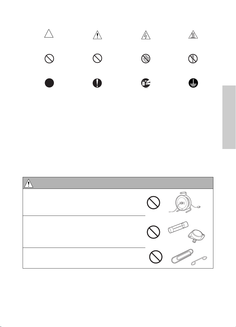
WARNING: Prohibited actions
Safety
● Do not use any cables or power cord not specified by
HP.
● Do not use any fuse or thermostat not specified by
HP.
● Safety will not be assured, leading to a risk of fire
and injury.
● Do not disable fuse functions or bridge fuse
terminals with wire, metal clips, solder, or similar
object.
ENWW Safety warnings 5
Page 14
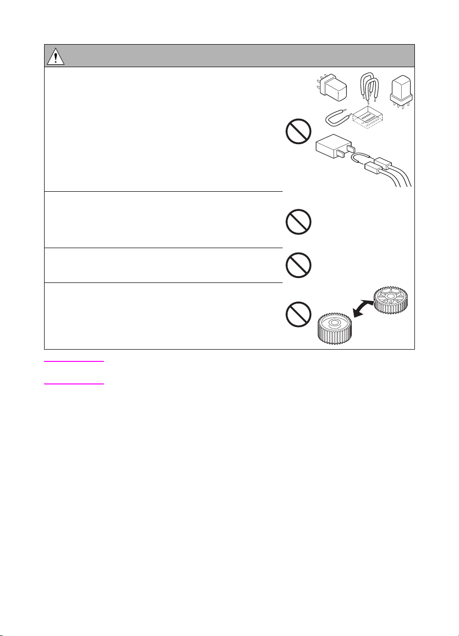
WARNING: Prohibited actions
● Do not disable relay functions (such as wedging
paper between relay contacts).
● Do not disable safety functions (interlocks, safety
circuits, and so forth). Safety will not be assured,
leading to a risk of fire and injury.
● Do not make any modification to the MFP unless
instructed by HP.
● Do not use parts not specified by HP.
Note Only qualified service personnel should disable relay functions and safety functions
when it is necessary to solve problems.
Checkpoints when performing on-site service
HP MFPs are extensively tested before shipping to ensure that all applicable safety standards
are met, and to protect the customer and customer engineer (hereafter called the CE) from the
risk of injury. However, in daily use, any electrical equipment may be subject to parts wear and
eventual failure. In order to maintain safety and reliability, the CE must perform regular safety
checks.
6Safety ENWW
Page 15
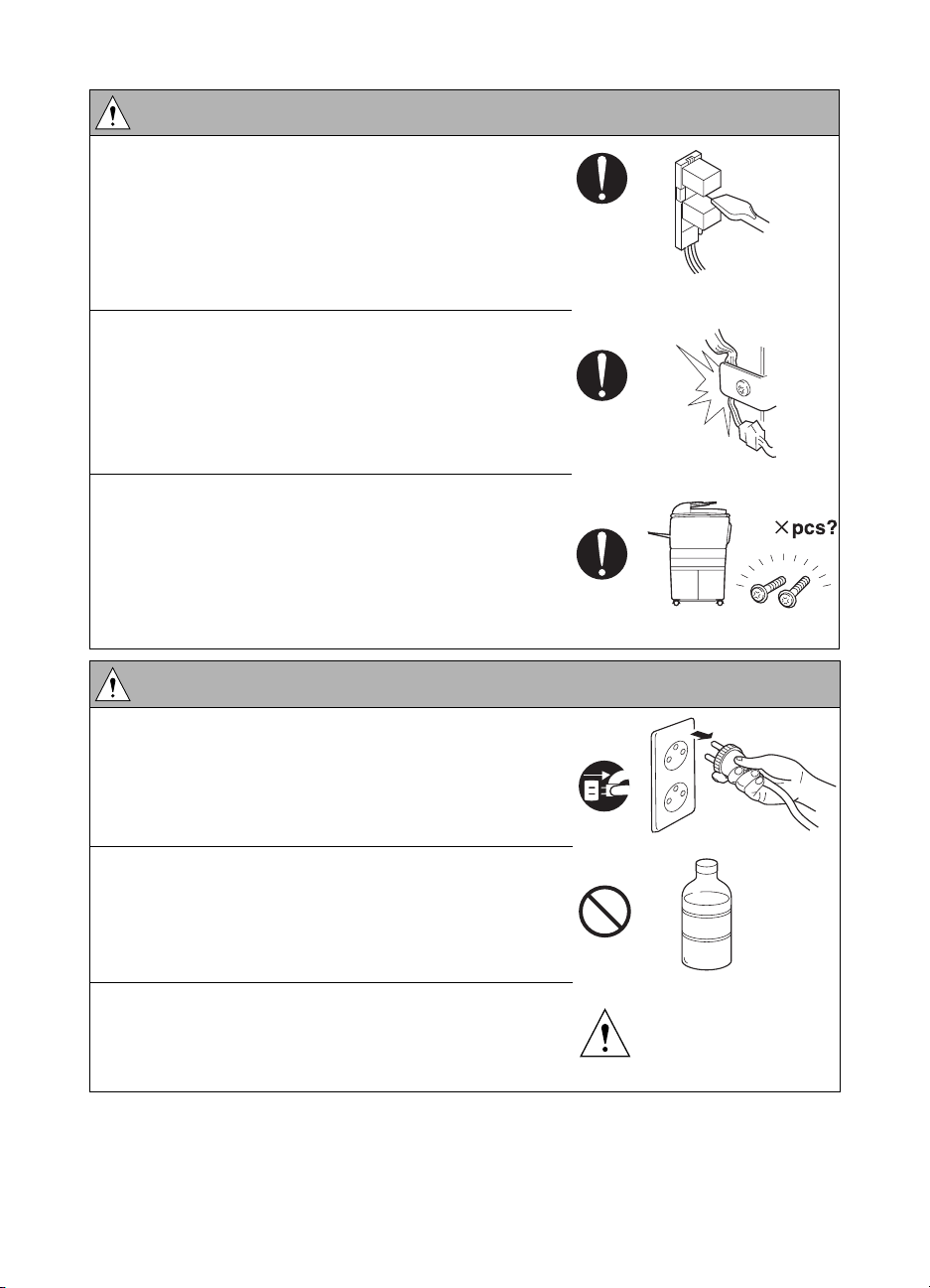
Power supply
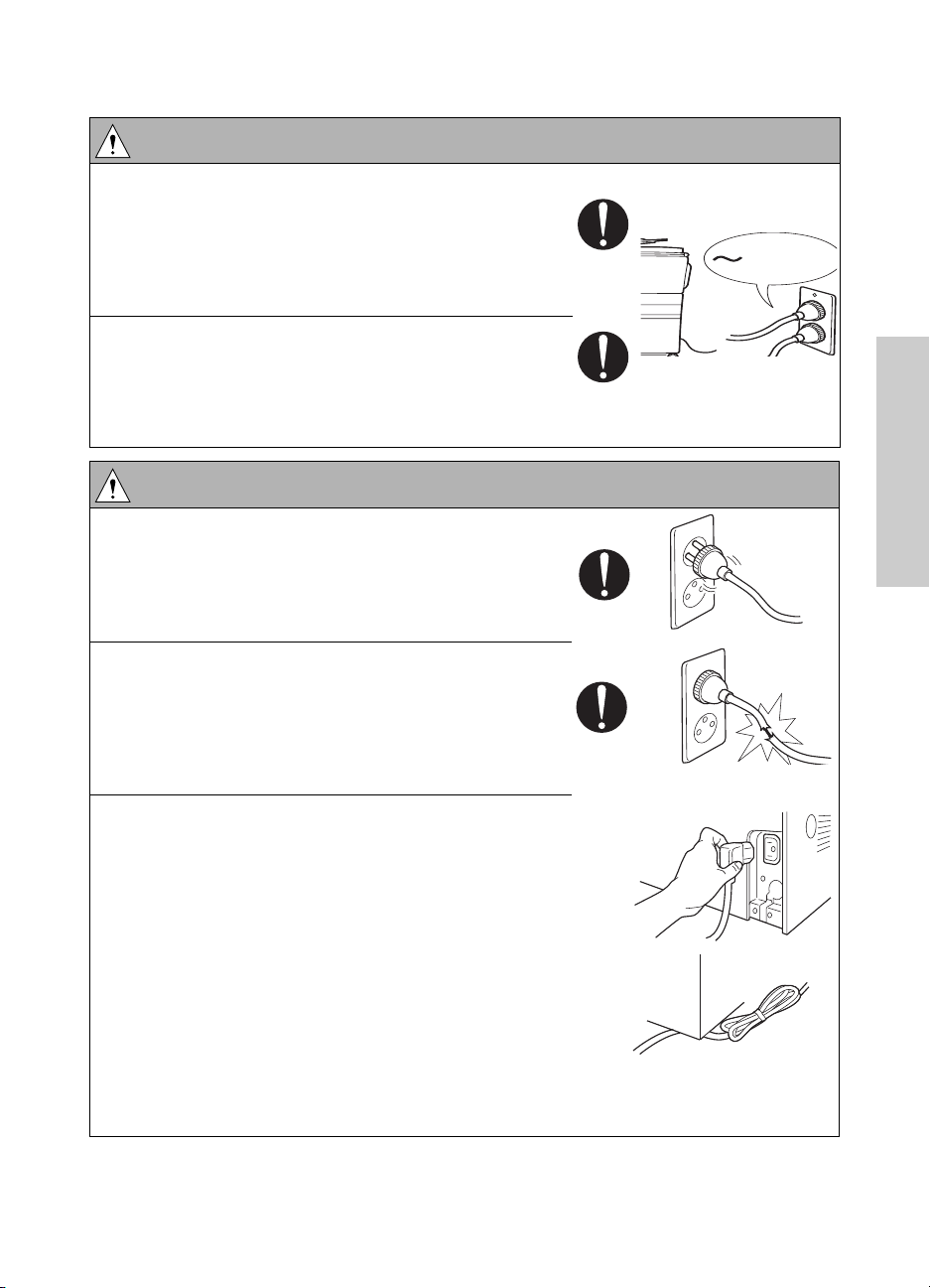
WARNING: Wall outlet
● Check that main voltage is as specified. Plug the
power cord into the dedicated wall outlet with a
capacity greater than the maximum power
consumption.
● If excessive current flows in the wall outlet, fire may
result.
● If two or more power cords are plugged into the wall
outlet, the total load must not exceed the rating of
the wall outlet.
● If excessive current flows in the wall outlet, fire may
result.
kw
WARNING: Power plug and cord
● Make sure the power cord is plugged in the wall
outlet securely.
Contact problems may lead to increased resistance,
overheating, and the risk of fire.
● Check whether the power cord is damaged. Check
whether the sheath is damaged.
If the power plug, cord, or sheath is damaged,
replace with a new power cord (with plugs on both
ends) specified by HP. Using the damaged power
cord may result in fire or electric shock.
● When using the power cord (inlet type) that came
with this MFP, be sure to observe the following
precautions:
a Make sure the MFP-side power plug is securely
inserted in the socket on the rear panel of the
MFP.
Secure the cord with a fixture properly.
b If the power cord or sheath is damaged, replace
with a new power cord (with plugs on both ends)
specified by HP.
If the power cord (inlet type) is not connected to
the MFP securely, a contact problem may lead to
increased resistance, overheating, and risk of
fire.
Safety
ENWW Safety warnings 7
Page 16
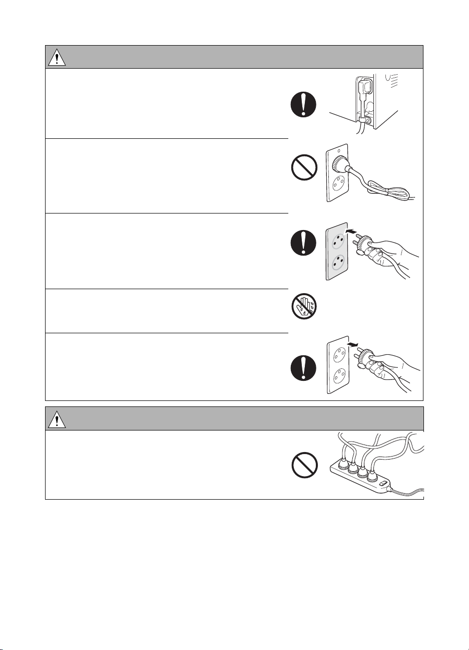
WARNING: Power plug and cord
●
Check whether the power cord is not stepped on or
pinched by a table and so on.
● Overheating may occur there, leading to a risk of
fire.
● Do not bundle or tie the power cord.
Overheating may occur there, leading to a risk of
fire.
● Check whether dust has collected around the power
plug and wall outlet.
Using the power plug and wall outlet without
removing dust may result in fire.
● Do not insert the power plug into the wall outlet with
a wet hand.
The risk of electric shock exists.
● When unplugging the power cord, grasp the plug,
not the cable.
The cable may be broken, leading to a risk of fire
and electric shock.
WARNING: Wiring
● Never use multi-plug adapters to plug multiple power
cords in the same outlet.
If used, the risk of fire exists.
8Safety ENWW
Page 17
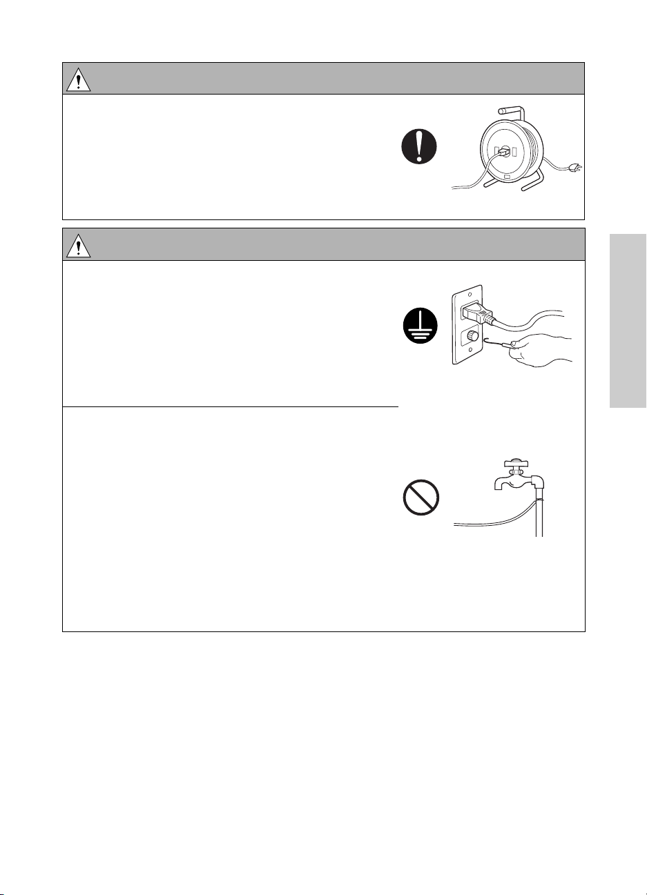
WARNING: Wiring
● When an extension cord is required, use a specified
one.
Current that can flow in the extension cord is limited,
so using an extension cord that is too long may
result in fire.
Do not use an extension cable reel with the cable
taken up. Fire may result.
WARNING: Ground lead
● Check whether the MFP is grounded properly.
If current leakage occurs in an ungrounded MFP,
you may suffer electric shock while operating the
MFP. Connect the ground lead to one of the
following points:
a Ground terminal of wall outlet
b Ground terminal for which Class D work has been
done
● Pay attention to the point where the ground lead is
connected.
Connecting the ground lead to an improper point as
listed below results in a risk of explosion and electric
shock:
a Gas pipe (A risk of explosion or fire exists.)
b Lightning rod (A risk of electric shock or fire
exists.)
c Telephone line ground (A risk of electric shock or
fire exists in the case of lightning.)
d Water pipe or faucet (It may include a plastic
portion.)
Safety
ENWW Safety warnings 9
Page 18
Installation requirements
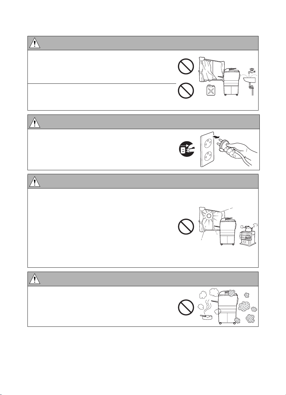
WARNING: Prohibited installation place
● Do not place the MFP near flammable materials
such as curtains or volatile materials that may catch
fire.
A risk of fire exists.
● Do not place the MFP in a place exposed to water
such as rain water.
A risk of fire and electric shock exists.
WARNING: Non-operational handling
● When the MFP is not used over an extended period
of time (holidays, and so forth), turn it off and unplug
the power cord.
Dust collected around the power plug and outlet may
cause fire.
CAUTION: Temperature and humidity
● Do not place the MFP in a place exposed to direct
sunlight or near a heat source such as a heater.
A risk of degradation in MFP performance or
deformation exists.
Do not place the MFP in a place exposed to cool
wind. Recommended temperature and humidity are
as follows:
Temperature: 10
Humidity: 10 percent to 80 percent (no dew
condensation)
° C to 30° C (50° F to 86° F)
CAUTION: Ventilation
● Do not place the MFP in a place where there is much
dust, cigarette smoke, or ammonia gas.
Place the MFP in a well-ventilated location to
prevent MFP problems and image issues.
10 Safety ENWW
Page 19

CAUTION: Ventilation
● The MFP generates ozone gas during operation, but
it is not sufficient to be harmful to the human body.
If a bad smell of ozone is present in the following
cases, ventilate the room.
● When the MFP is used in a poorly ventilated
room
● When making a lot of copies
● When using multiple MFPs at the same time
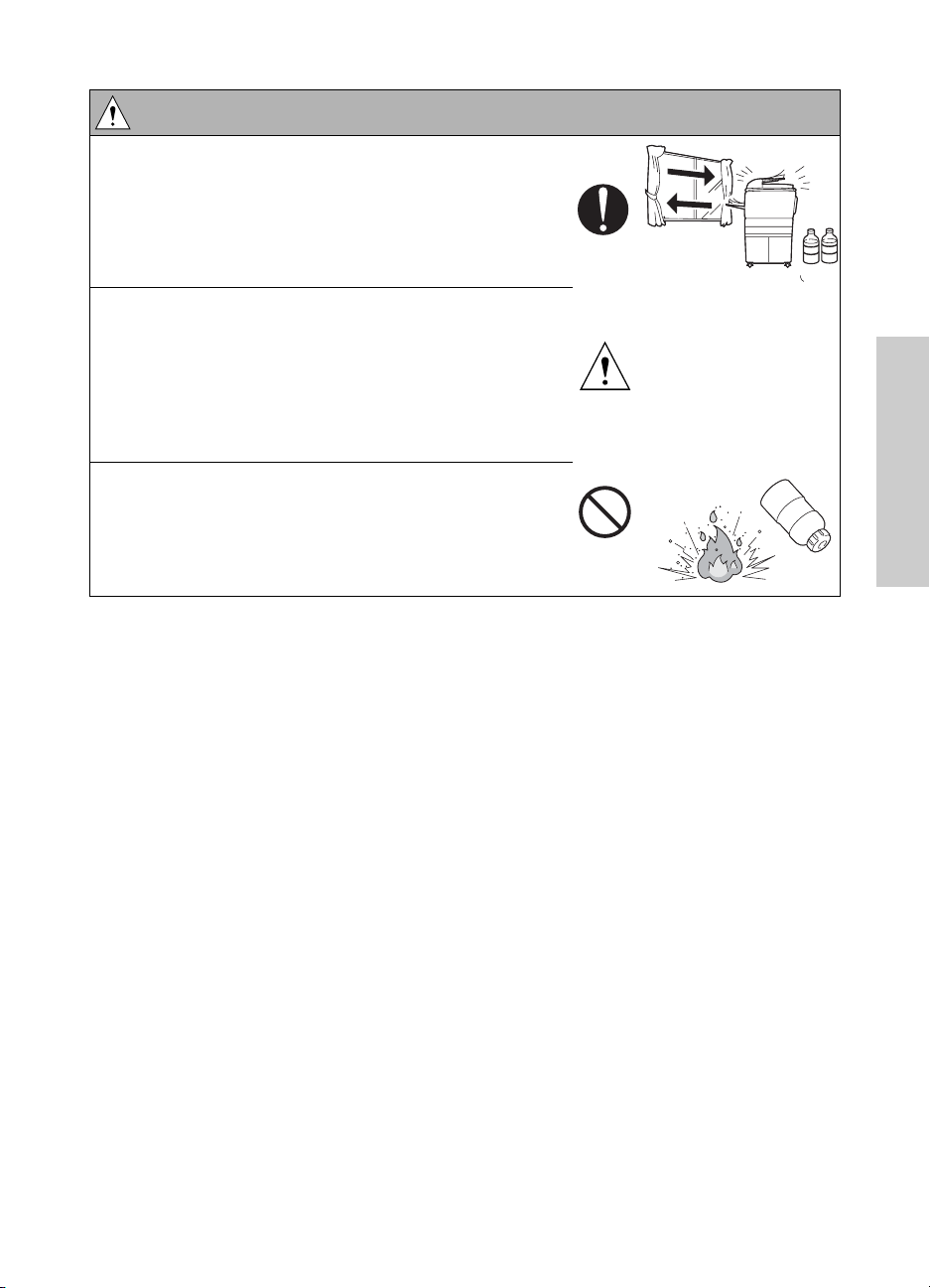
CAUTION: Vibration
● When installing the MFP, read the installation guide
thoroughly. Be sure to install the MFP on a level and
sturdy surface.
Constant vibration will cause problems.
● Be sure to lock the caster stoppers.
In the case of an earthquake and so on, the MFP
may slide, leading to a injury.
CAUTION: Inspection before servicing
● Before conducting an inspection, read all relevant
documentation (service handbook, technical notices,
and so forth) and proceed with the inspection
following the prescribed procedure in safety clothes,
using only the prescribed tools. Do not make any
adjustment not described in the documentation.
If the prescribed procedure or tool is not used, the
MFP may break and a risk of injury or fire exists.
Safety
● Before conducting an inspection, be sure to
disconnect the power cords from the MFP and
optional accessories.
When the power plug is inserted in the wall outlet,
some units are still powered even if the power switch
is turned off. A risk of electric shock exists.
ENWW Safety warnings 11
Page 20
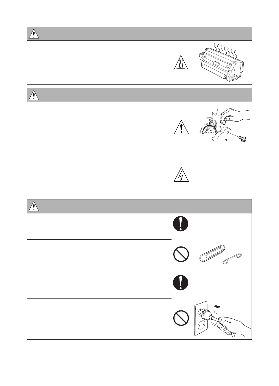
CAUTION: Inspection before servicing
●
The area around the fuser unit is hot.
You may get burned.
WARNING: Work performed with the MFP powered
● Be careful when making adjustments or performing
an operation check with the MFP powered on.
If you make adjustments or perform an operation
check with the external cover detached, you may
touch live or high-voltage parts or you may be
caught in moving gears or the timing belt, leading to
a risk of injury.
● Be careful when servicing with the external cover
detached.
High-voltage exists around the drum unit. A risk of
electric shock exists.
WARNING: Safety checkpoints
● Check the exterior and frame for edges, burrs, and
other damage.
The user or CE may be injured.
● Do not allow any metal parts such as clips, staples,
and screws to fall into the MFP.
They can short internal circuits and cause electric
shock or fire.
● Check wiring for squeezing and any other damage.
Current can leak, leading to a risk of electric shock
or fire.
● When disconnecting connectors, grasp the
connector, not the cable. (Specifically, connectors of
the AC line and high-voltage parts.)
Current can leak, leading to a risk of electric shock
or fire.
12 Safety ENWW
Page 21
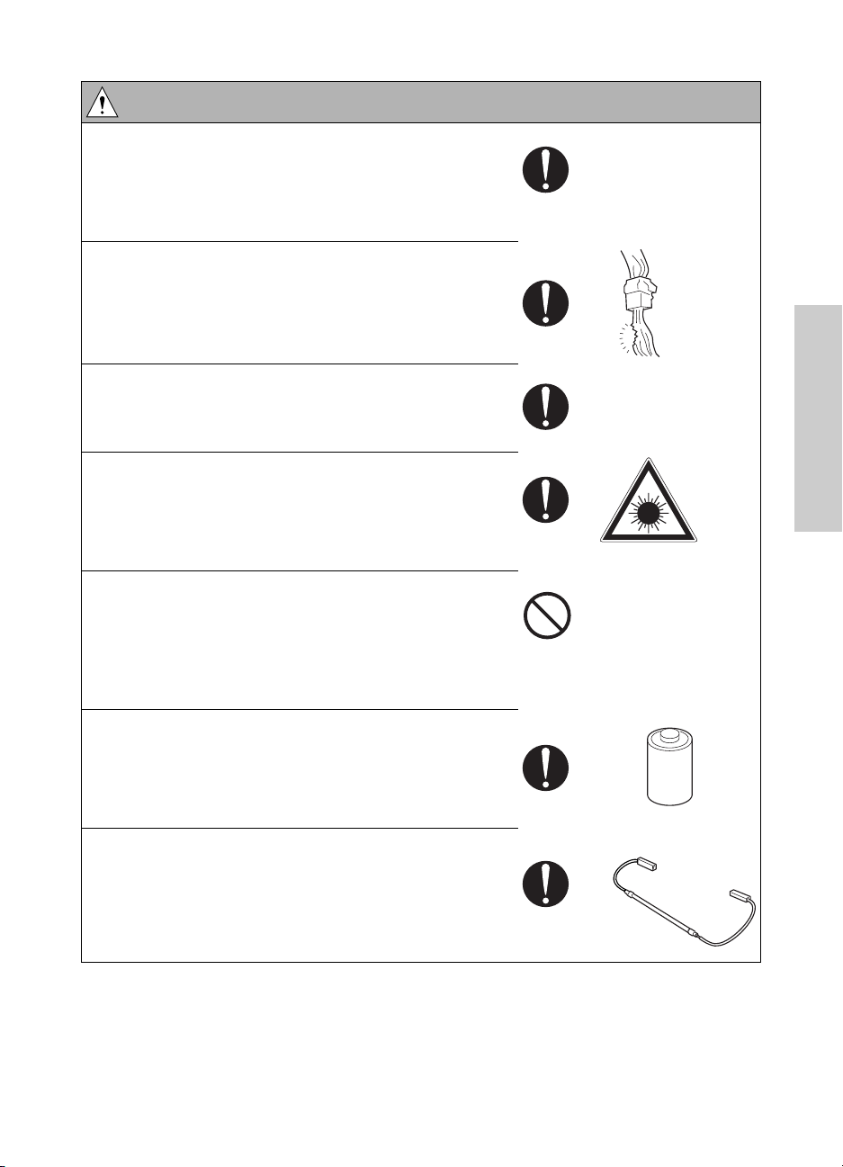
WARNING: Safety checkpoints
● Carefully remove all toner remnants and dust from
electrical parts and electrode units such as a
charging corona unit.
Current can leak, leading to a risk of MFP trouble or
fire.
● Check high-voltage cables and sheaths for any
damage.
Current can leak, leading to a risk of electric shock
or fire.
● Check electrode units such as a charging corona
unit for deterioration and sign of leakage.
Current can leak, leading to a risk of trouble or fire.
● Before disassembling or adjusting the laser/scanner
assembly incorporating a laser, make sure that the
power cord has been disconnected.
The laser light can enter your eye, leading to a risk
of loss of eyesight.
● Do not remove the cover of the laser/scanner
assembly. Do not supply power with the
laser/scanner assembly shifted from the specified
mounting position.
The laser light can enter your eye, leading to a risk
of loss of eyesight.
Safety
● When replacing a lithium battery, replace it with a
new lithium battery specified in the parts guide
manual. Dispose of the used lithium battery using
the method specified by local authority.
Improper replacement can cause explosion.
● After replacing a part to which AC voltage is applied
(for example, optical lamp and fuser lamp), be sure
to check the installation state.
A risk of fire exists.
ENWW Safety warnings 13
Page 22
WARNING: Safety checkpoints
●
Check the interlock switch and actuator for
loosening and check whether the interlock functions
properly.
If the interlock does not function, you may receive an
electric shock or be injured when you insert your
hand in the MFP (for example, when clearing a
paper jam).
● Make sure the wiring cannot come into contact with
sharp edges, burrs, or other pointed parts.
Current can leak, leading to a risk of electric shock
or fire.
● Make sure that all screws, components, wiring,
connectors, and so forth that were removed for
safety check and maintenance have been reinstalled
in the original location. (Pay special attention to
forgotten connectors, pinched cables, forgotten
screws, and so forth).
A risk of MFP trouble, electric shock, and fire exists.
WARNING: Handling of service materials
● Unplug the power cord from the wall outlet.
● Drum cleaner (isopropyl alcohol) and roller cleaner
(acetone-based) are highly flammable and must be
handled with care. A risk of fire exists.
● Do not replace the cover or turn the MFP on before
any solvent remnants on the cleaned parts have fully
evaporated.
A risk of fire exists.
● Use only a small amount of cleaner at a time and
take care not to spill any liquid. If this happens,
immediately wipe it off.
A risk of fire exists.
14 Safety ENWW
Page 23
WARNING: Handling of service materials
● When using any solvent, ventilate the room well.
Breathing large quantities of organic solvents can
lead to discomfort.
● Toner and developer are not harmful substances,
but care must be taken not to breathe excessive
amounts or let the substances come into contact
with eyes, and so forth. It may be stimulative.
If the substances get in the eye, rinse with plenty of
water immediately. When symptoms are noticeable,
consult a physician.
● Never throw the used toner bottle and toner into fire.
You may be burned due to dust explosion.
Measures to take in case of an accident
If an accident has occurred, the distributor who has been notified first must immediately take
emergency measures to provide relief to affected persons and to prevent further damage.
If a report of a serious accident has been received from a customer, an on-site evaluation must
be carried out quickly and HP must be notified.
To determine the cause of the accident, conditions and materials must be recorded through
direct on-site checks, in accordance with instructions issued by HP.
Conclusion
Safety of users and customer engineers depends highly on accurate maintenance and
administration. Therefore, safety can be maintained by the appropriate daily service work
conducted by the customer engineer.
When performing service, each MFP on the site must be tested for safety. The customer
engineer must verify the safety of parts and ensure appropriate management of the equipment.
Safety
ENWW Safety warnings 15
Page 24

Regulatory statements
FCC Class A Statement
This equipment has been tested and found to comply with the limits for a Class A digital device,
pursuant to Part 15 of the FCC Rules. These limits are designed to provide reasonable
protection against harmful interference when the equipment is operated in a commercial
environment. This equipment generates, uses, and can radiate radio frequency energy and, if
not installed and used in accordance with the instruction manual, may cause harmful
interference to radio communications. Operation of this equipment in a residential area is likely
to cause harmful interference, in which case the user will be required to correct the interference
at his own expense. The end user of this product should be aware that any changes or
modifications made to this equipment without the approval of Hewlett-Packard could result in
the product not meeting the Class A limits, in which case the FCC could void the user’s authority
to operate the equipment.
Note Any changes or modifications to the MFP that are not expressly approved by HP
could void the user’s authority to operate this equipment.
Use of a shielded interface cable is required to comply with the Class A limits of
Part 15 of the FCC Rules.
Safety information
Safety circuits
This MFP is provided with the following safety circuits to prevent MFP issues from resulting in
serious accidents.
Overall protection circuit
L2 and L3 (fuser heater lamps) overheating prevention circuit
These safety circuits are described below to provide the service engineer with a renewed
awareness of them in order to prevent servicing errors that may impair their functions.
16 Safety ENWW
Page 25
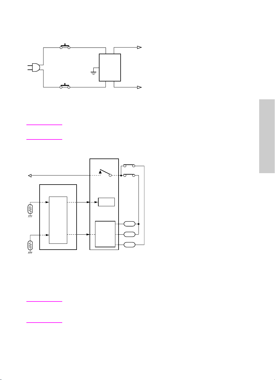
Overall protection circuit
CBR1
NF
CBR2
Protection by CBR1 and CBR2 (circuit breakers)
CBR1 and CBR2 interrupt the AC line instantaneously when an excessive current flows due to a
short in the AC line.
CAUTION The CBR1 and CBR2 functions must not be deactivated under any
circumstances.
Protection by L2, L3 and L4 (fuser heater lamps) overheating prevention circuit
DCPS
RL1
PRCB
TS2
TS1
Safety
RL1
TH2
Control
section
AC driver
section
TH1
L2
L3
L4
Protection by software
The output voltage from TH1 (fuser temperature sensor 1) is read by the CPU. If this voltage is
abnormal, L2 (fuser heater lamp 1), L3 (fuser heater lamp 2), L4 (fuser heater lamp 3) and RL1
(main relay) are turned off.
CAUTION Do not change the gap between the roller and TH1. When replacing TH1, check
the specified mounting dimensions. The RL1 function must not be deactivated
under any circumstances.
ENWW Safety information 17
Page 26

Protection by the hardware circuit
The output voltages from TH1 and TH2 (fuser temperature sensors) are compared with the
abnormality judgment reference value in the comparator circuit. If the output voltage from TH1
or TH2 exceeds the reference value, L2 (fuser heater lamp 1), L3 (fuser heater lamp 2), L4
(fuser heater lamp 3) and RL1 (main relay) are turned off.
CAUTION Periodically check the TH2 face contacting the roller, and replace TH2 if any
abnormality is detected.
Since TH1 (fuser temperature sensor) face does not contact the roller, check
the distance from the roller and the sensor orientation if any abnormality is
detected.
The RL1 function must not be deactivated under any circumstances.
Protection by TS1 (thermostat/U) and TS2 (thermostat/L)
When the temperature of the fuser roller (upper/lower) exceeds the specified value, TSs are
turned off, thus interrupting the power to L2 (fuser heater lamp/1), L3 (fuser heater lamp/2), and
L4 (fuser heater lamp/3) directly.
CAUTION Do not use any other electrical conductor in place of TS1 and TS2. Do not
change the distance between the roller and TS (thermostat).
18 Safety ENWW
Page 27
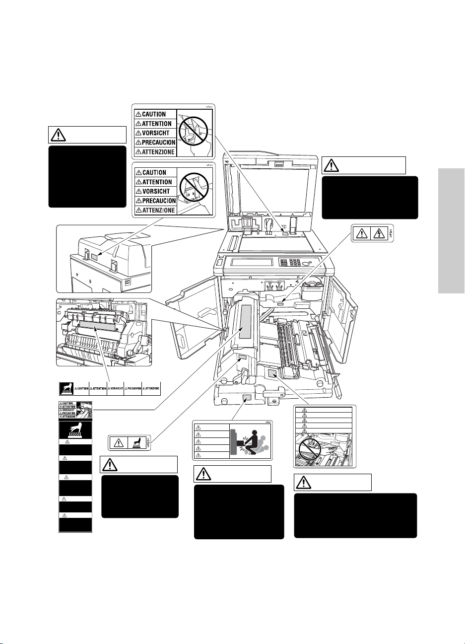
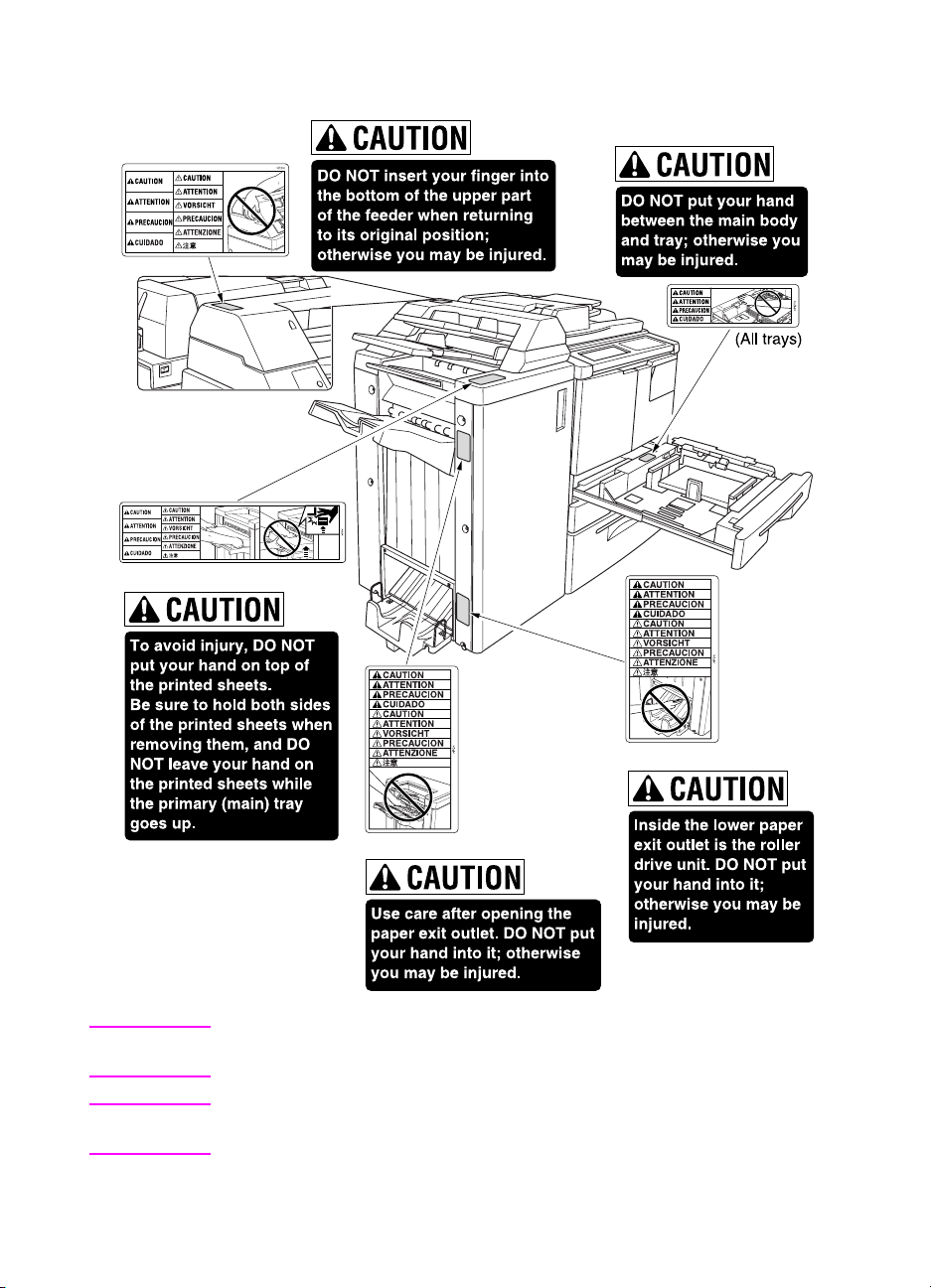
Safety labels on the MFPs
Caution labels shown below are attached in some areas on/in the MFP. When accessing these
areas for maintenance, repair, or adjustment, special care should be taken to avoid burns and
electric shock.
CAUTION
DO NOT INSERT
your finger into the
two RADF hinge
portions;
otherwise you may
be injured.
WARNING
This area generates
high voltage. If touched,
electrical shock may
occur. DO NOT TOUCH.
Safety
CAUTION
ATTENTION
VORSICHT
PRECAUCION
ATTENZIONE
CAUTION
DO NOT put your hand between
the main body and developing
fixing unit; otherwise you may
be injured.
CAUTION
High temperature!
Do not touch. Use care
when clearing paper.
ATTENTION
Temp rature lev e!
Risque de br lure. Soyez
prudent en retirant la
feuille coinc e.
VORSICHT
Hei§e OberflŠche!
Brandverletzungsgefahr.
Bei Beseitigung von
Papierstaus vorsichtig
vorgehen.
PRECAUCION
ÁTemperatura alta!
No tocar. Tener cuidado al
remover el papel.
ATTENZIONE
Alta temperatura!
Non toccare. Agire con
prudenza nel rimuovere la
carta.
CAUTION
The fixing unit is
very hot. To avoide
getting burned, DO
NOT TOUCH.
CAUTION
ATTENTION
VORSICHT
PRECAUCION
ATTENZIONE
CAUTION
The conveyance fixing
unit is heavy. Use care
and draw it out gently;
otherwise you may be
injured.
ENWW Safety labels on the MFPs 19
Page 28
(Finisher with Cover
Sheet Feeder only)
(Punch Kit)
(Q3634A Finisher only)
(Q3634A Finisher)
CAUTION You may be burned or injured if you touch any area that you are advised by
any caution label to avoid.
CAUTION Do not remove caution labels. If any caution label has come off or is soiled and
therefore the caution cannot be read, contact our service office.
20 Safety ENWW
Page 29
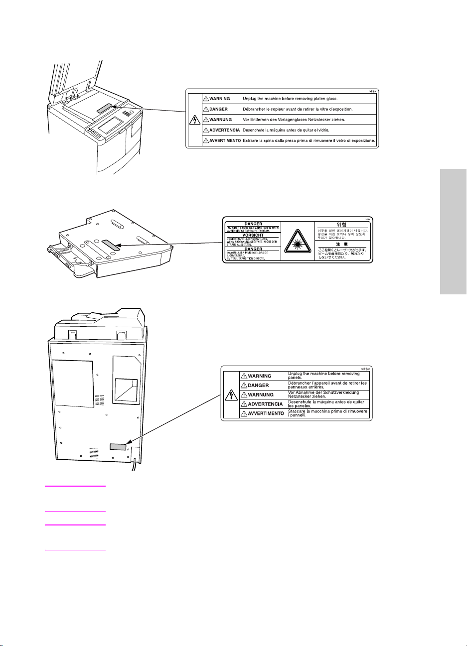
Scanner section
Laser/scanner assembly
Rear cover
Safety
CAUTION You may be burned or injured if you touch any area that you are advised by
any caution label to avoid.
CAUTION Do not remove caution labels. If any caution label has come off or is soiled and
therefore the caution cannot be read, contact our service office.
ENWW Safety labels on the MFPs 21
Page 30
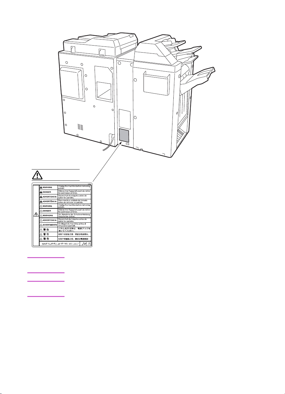
WARNING
CAUTION You may be burned or injured if you touch any area that you are advised by
any caution label to avoid.
CAUTION Do not remove caution labels. If any caution label has come off or is soiled and
therefore the caution cannot be read, contact our service office.
22 Safety ENWW
Page 31

3MFP overview
Overview of system . . . . . . . . . . . . . . . . . . . . . . . . . . . . . . . . . . . . . . . . . . . . 24
hp LaserJet 9055mfp/9065mfp product specifications . . . . . . . . . . . . . . . . . . 25
Type . . . . . . . . . . . . . . . . . . . . . . . . . . . . . . . . . . . . . . . . . . . . . . . . . . . . 25
Functions . . . . . . . . . . . . . . . . . . . . . . . . . . . . . . . . . . . . . . . . . . . . . . . . 25
Applicable copy paper . . . . . . . . . . . . . . . . . . . . . . . . . . . . . . . . . . . . . . 26
Options. . . . . . . . . . . . . . . . . . . . . . . . . . . . . . . . . . . . . . . . . . . . . . . . . . 26
Particulars of machine . . . . . . . . . . . . . . . . . . . . . . . . . . . . . . . . . . . . . . 26
Maintenance and life . . . . . . . . . . . . . . . . . . . . . . . . . . . . . . . . . . . . . . . 26
Environmental conditions . . . . . . . . . . . . . . . . . . . . . . . . . . . . . . . . . . . . 26
Central cross-sectional view . . . . . . . . . . . . . . . . . . . . . . . . . . . . . . . . . . . . . 27
Drive system diagram . . . . . . . . . . . . . . . . . . . . . . . . . . . . . . . . . . . . . . . . . . 28
Fuser/web drive section . . . . . . . . . . . . . . . . . . . . . . . . . . . . . . . . . . . . . 28
Drum drive section . . . . . . . . . . . . . . . . . . . . . . . . . . . . . . . . . . . . . . . . . 29
Developing drive section . . . . . . . . . . . . . . . . . . . . . . . . . . . . . . . . . . . . 29
Paper feed/vertical conveyance/tray up drive sections . . . . . . . . . . . . . 30
Tray 1 paper feed/automatic duplex unit (ADU) pre-registration
drive section. . . . . . . . . . . . . . . . . . . . . . . . . . . . . . . . . . . . . . . . . . 31
Charging and transfer/separation wire cleaning drive section . . . . . . . . 32
Automatic Duplex Unit (ADU) conveyance drive section . . . . . . . . . . . . 33
Paper exit drive section . . . . . . . . . . . . . . . . . . . . . . . . . . . . . . . . . . . . . 34
Toner supply drive section . . . . . . . . . . . . . . . . . . . . . . . . . . . . . . . . . . . 34
Optics drive section . . . . . . . . . . . . . . . . . . . . . . . . . . . . . . . . . . . . . . . . 35
MFP overview
ENWW 23
Page 32

Overview of system
24 MFP overview ENWW
Page 33

hp LaserJet 9055mfp/9065mfp product specifications
Type
Installation type
Console type (floor-mounted)
Copying method
Indirect electrostatic method
Document tray type
Fixed
Photosensitive material
OPC
Sensitizing method
Laser writing
Paper feed trays
Three stacked trays (two for 500 sheets of
2
80 g/m
1500 sheets of 80 g/m
Tray 1 tray for various paper sizes
(100 sheets of 80 g/m
or 20 lb paper, one for
2
or 20 lb paper)
2
or 20 lb paper)
Q3637A (4000 sheets of 80 g/m2 or 20 lb
paper) (optional)
Q3638A (4000 sheets of 80 g/m2 or 20 lb
paper) (optional)
Functions
Applicable document types
Sheets, books, and solid objects
Document size
A3/11 by 17 maximum
Copy paper size
● Metric area
A3 to A6R, F4
● Inch area
11 by 17 to 8.5 by 5.5
Wide paper (up to 314 mm by 459 mm
maximum)
Magnifications
Fixed magnifications
• Metric area
x1.00, x2.00, x1.41, x1.22, x1.15, x0.86,
0.82, x0.71, x0.50
• Inch area
x1.00, x2.00, x1.55, x1.29, x1.21, x0.93,
0.77, x0.65, x0.50
Special ratio magnifications
3 modes
Zoom magnifications
x0.25 to x4.00 (in 1 percent steps)
Vertical magnifications
x0.25 to x4.00 (in 1 percent steps)
Horizontal magnifications
x0.25 to x4.00 (in 1 percent steps)
Warm-up time
5.5 minutes maximum 20° C, rated voltage 9055
6 minutes maximum 20° C, rated voltage 9065
First copy out time (FCOT)
Mode A4/8.5 by 11
Manual 3.4 seconds or shorter (9055)
3.1 seconds or shorter (9065)
Straight paper ejection, platen mode, life
*
size, non AE or AES, without finisher, and
paper feed fro
Continuous copy speed (life size,
copies/min)
Size cpm
A4/8.5 by 11 55 (9055)
Continuous copy count
1 to 9999
Copy density selection
AE or AES, manual (9 steps)
Arbitrary density (2 modes)
m Tray 2
65 (9065)
MFP overview
ENWW hp LaserJet 9055mfp/9065mfp product specifications 25
Page 34

E-RDH memory capacity
Standard 64 MB
Maximum 192 MB
Applicable copy paper
Plain paper
2
High-quality paper of 60 g/m
17 lb to 90 g/m
2
, or 24 lb
Special paper (Tray 1 feed only)
OHT film
Blueprint master paper
(both Tray 1 tray and stacked trays)
Ta bs
Plain paper of 50 g/m
2
59 g/m
Plain paper of 91 g/m
200 g/m
, or 16 lb
2
, or 45 lb
2
2
, or
, or 13 lb to
, or 24 lb to
Power consumption
230 V Machine: 2300 W maximum (full
option)
120 V Machine: 1920 W maximum (full
option)
Weight: Approximately 203 kg (447 lb)
External dimensions
1140
650
766
Options
HCI: Q3637A (Letter/A4), Q3638A
(Ledger/A3)
Paper exit Tray 100 sheet: Q3640A
Hard disk: Q3642A
Finisher: Q3633A, Q3634A
Cover sheet feeder: Post inserter Q3636A
Puncher: Punch Kit
• 2-hole Q3635A
• 3-hole Q3689A
• 4-hole Swedish Q3691A
• 4-hole Q3690A
Print Controller: Q3639A
Particulars of machine
Power supply
230 VAC -14 percent to 10.6 percent
50Hz/60Hz
120 VAC ±10 percent 60 Hz
(mm)
Maintenance and life
Periodic maintenance: Every 250,000
copies
Machine life: 5,000,000 copies or 5 years
Environmental conditions
Temperature: 10° C to 30° C (50° F to
86° F)
Humidity: 10 percent to 80 percent RH
Note The information herein may be
subject to change for
improvement without notice.
26 MFP overview ENWW
Page 35

Central cross-sectional view
ENWW Central cross-sectional view 27
MFP overview
Page 36

Drive system diagram
Fuser/web drive section
Cleaning web unwinding shaft
Cleaning web wind-up shaft
Reverse/exit switching gate
Web SD (SD2)
Ratchet
FRONT
Fixing input gear
Fixing upper roller
Fixing lower roller
Decurler roller
Reverse gate SD (SD7)
Fixing motor (M4)
28 MFP overview ENWW
Page 37

Drum drive section
Separation claw swing cam
Separation claw SD
(SD1)
Drum
Separation claw section
Toner conveyance screw
Developing drive section
Drum motor (M2)
Toner guide roller
Drum motor (M2)
Toner conveyance screw
MFP overview
Developing sleeve
Developing motor (M3)
Agitator wheel
ENWW Drive system diagram 29
Agitator screws
Page 38

Paper feed/vertical conveyance/tray up drive sections
30 MFP overview ENWW
Page 39

Tray 1 paper feed/automatic duplex unit (ADU) pre-registration drive
section
ENWW Drive system diagram 31
MFP overview
Page 40

Charging and transfer/separation wire cleaning drive section
[Charging corona unit]
Charging cleaning motor (M14)
[Transfer and separation corona unit]
FRONT
Transfer/separation cleaning motor (M10)
32 MFP overview ENWW
Page 41

Automatic Duplex Unit (ADU) conveyance drive section
ENWW Drive system diagram 33
MFP overview
Page 42

Paper exit drive section
Paper exit motor (M7)
Paper exit roller
Toner supply drive section
Exit conveyance roller
34 MFP overview ENWW
Page 43

Optics drive section
Scanner motor (M11)
Scanner drive wire (rear)
Exposure unit
FRONT
Scanner drive wire (front)
V-mirror unit
ENWW Drive system diagram 35
MFP overview
Page 44

36 MFP overview ENWW
Page 45

4MFP unit explanation
External section . . . . . . . . . . . . . . . . . . . . . . . . . . . . . . . . . . . . . . . . . . . . . . . 40
Composition . . . . . . . . . . . . . . . . . . . . . . . . . . . . . . . . . . . . . . . . . . . . . . 40
Drive section . . . . . . . . . . . . . . . . . . . . . . . . . . . . . . . . . . . . . . . . . . . . . . . . . 41
Composition . . . . . . . . . . . . . . . . . . . . . . . . . . . . . . . . . . . . . . . . . . . . . . 41
Mechanisms . . . . . . . . . . . . . . . . . . . . . . . . . . . . . . . . . . . . . . . . . . . . . . 41
M2 (drum) control. . . . . . . . . . . . . . . . . . . . . . . . . . . . . . . . . . . . . . . . . . 42
M4 (fuser) control . . . . . . . . . . . . . . . . . . . . . . . . . . . . . . . . . . . . . . . . . . 42
Scanner section . . . . . . . . . . . . . . . . . . . . . . . . . . . . . . . . . . . . . . . . . . . . . . . 44
Composition . . . . . . . . . . . . . . . . . . . . . . . . . . . . . . . . . . . . . . . . . . . . . . 44
Mechanisms . . . . . . . . . . . . . . . . . . . . . . . . . . . . . . . . . . . . . . . . . . . . . . 44
M11 (scanner) control . . . . . . . . . . . . . . . . . . . . . . . . . . . . . . . . . . . . . . 45
Exposure control . . . . . . . . . . . . . . . . . . . . . . . . . . . . . . . . . . . . . . . . . . 48
Original read control . . . . . . . . . . . . . . . . . . . . . . . . . . . . . . . . . . . . . . . . 48
APS control . . . . . . . . . . . . . . . . . . . . . . . . . . . . . . . . . . . . . . . . . . . . . . 49
AE control. . . . . . . . . . . . . . . . . . . . . . . . . . . . . . . . . . . . . . . . . . . . . . . . 51
Laser scanner unit . . . . . . . . . . . . . . . . . . . . . . . . . . . . . . . . . . . . . . . . . . . . . 52
Composition . . . . . . . . . . . . . . . . . . . . . . . . . . . . . . . . . . . . . . . . . . . . . . 52
Mechanisms . . . . . . . . . . . . . . . . . . . . . . . . . . . . . . . . . . . . . . . . . . . . . . 52
M15 (polygon) control . . . . . . . . . . . . . . . . . . . . . . . . . . . . . . . . . . . . . . 53
Image write control. . . . . . . . . . . . . . . . . . . . . . . . . . . . . . . . . . . . . . . . . 53
Drum unit . . . . . . . . . . . . . . . . . . . . . . . . . . . . . . . . . . . . . . . . . . . . . . . . . . . . 56
Composition . . . . . . . . . . . . . . . . . . . . . . . . . . . . . . . . . . . . . . . . . . . . . . 56
Mechanisms . . . . . . . . . . . . . . . . . . . . . . . . . . . . . . . . . . . . . . . . . . . . . . 56
Separation claw control . . . . . . . . . . . . . . . . . . . . . . . . . . . . . . . . . . . . . 57
Paper guide plate control . . . . . . . . . . . . . . . . . . . . . . . . . . . . . . . . . . . . 57
Corona unit section . . . . . . . . . . . . . . . . . . . . . . . . . . . . . . . . . . . . . . . . . . . . 58
Composition . . . . . . . . . . . . . . . . . . . . . . . . . . . . . . . . . . . . . . . . . . . . . . 58
Mechanisms . . . . . . . . . . . . . . . . . . . . . . . . . . . . . . . . . . . . . . . . . . . . . . 58
Charging control. . . . . . . . . . . . . . . . . . . . . . . . . . . . . . . . . . . . . . . . . . . 58
Transfer/separation control . . . . . . . . . . . . . . . . . . . . . . . . . . . . . . . . . . 59
M14 (charger cleaning) control . . . . . . . . . . . . . . . . . . . . . . . . . . . . . . . 60
M10 (transfer/separation cleaning) control. . . . . . . . . . . . . . . . . . . . . . . 61
PCL/TSL control. . . . . . . . . . . . . . . . . . . . . . . . . . . . . . . . . . . . . . . . . . . 62
ENWW 37
MFP unit explanation
Page 46

Developing unit . . . . . . . . . . . . . . . . . . . . . . . . . . . . . . . . . . . . . . . . . . . . . . . 63
Composition . . . . . . . . . . . . . . . . . . . . . . . . . . . . . . . . . . . . . . . . . . . . . . 63
Mechanisms . . . . . . . . . . . . . . . . . . . . . . . . . . . . . . . . . . . . . . . . . . . . . . 63
M3 (developing) control . . . . . . . . . . . . . . . . . . . . . . . . . . . . . . . . . . . . . 63
Developing bias control . . . . . . . . . . . . . . . . . . . . . . . . . . . . . . . . . . . . . 64
Dmax (maximum contrast) control. . . . . . . . . . . . . . . . . . . . . . . . . . . . . 65
Gradation correction control. . . . . . . . . . . . . . . . . . . . . . . . . . . . . . . . . . 67
Dot diameter correction control . . . . . . . . . . . . . . . . . . . . . . . . . . . . . . . 68
Toner density control . . . . . . . . . . . . . . . . . . . . . . . . . . . . . . . . . . . . . . . 69
FM4 (developing suction) control. . . . . . . . . . . . . . . . . . . . . . . . . . . . . . 69
Toner supply unit . . . . . . . . . . . . . . . . . . . . . . . . . . . . . . . . . . . . . . . . . . . . . . 70
Composition . . . . . . . . . . . . . . . . . . . . . . . . . . . . . . . . . . . . . . . . . . . . . . 70
Mechanisms . . . . . . . . . . . . . . . . . . . . . . . . . . . . . . . . . . . . . . . . . . . . . . 70
Toner level detection control . . . . . . . . . . . . . . . . . . . . . . . . . . . . . . . . . 71
M12 (toner supply) control . . . . . . . . . . . . . . . . . . . . . . . . . . . . . . . . . . . 72
Cleaning/toner recycle unit. . . . . . . . . . . . . . . . . . . . . . . . . . . . . . . . . . . . . . . 73
Composition . . . . . . . . . . . . . . . . . . . . . . . . . . . . . . . . . . . . . . . . . . . . . . 73
Mechanisms . . . . . . . . . . . . . . . . . . . . . . . . . . . . . . . . . . . . . . . . . . . . . . 73
Toner guide roller (TGR) control . . . . . . . . . . . . . . . . . . . . . . . . . . . . . . 74
Other control . . . . . . . . . . . . . . . . . . . . . . . . . . . . . . . . . . . . . . . . . . . . . 74
Tray 2/3 paper feed unit. . . . . . . . . . . . . . . . . . . . . . . . . . . . . . . . . . . . . . . . . 75
Composition . . . . . . . . . . . . . . . . . . . . . . . . . . . . . . . . . . . . . . . . . . . . . . 75
Mechanisms . . . . . . . . . . . . . . . . . . . . . . . . . . . . . . . . . . . . . . . . . . . . . . 75
First paper feed control . . . . . . . . . . . . . . . . . . . . . . . . . . . . . . . . . . . . . 77
Paper up drive control . . . . . . . . . . . . . . . . . . . . . . . . . . . . . . . . . . . . . . 79
Paper size detection control. . . . . . . . . . . . . . . . . . . . . . . . . . . . . . . . . . 80
No paper detection control. . . . . . . . . . . . . . . . . . . . . . . . . . . . . . . . . . . 81
Tray 4 paper feed unit . . . . . . . . . . . . . . . . . . . . . . . . . . . . . . . . . . . . . . . . . . 82
Composition . . . . . . . . . . . . . . . . . . . . . . . . . . . . . . . . . . . . . . . . . . . . . . 82
Mechanisms . . . . . . . . . . . . . . . . . . . . . . . . . . . . . . . . . . . . . . . . . . . . . . 82
First paper feed control . . . . . . . . . . . . . . . . . . . . . . . . . . . . . . . . . . . . . 84
Paper up drive control . . . . . . . . . . . . . . . . . . . . . . . . . . . . . . . . . . . . . . 86
Paper size detection control. . . . . . . . . . . . . . . . . . . . . . . . . . . . . . . . . . 87
No paper detection control. . . . . . . . . . . . . . . . . . . . . . . . . . . . . . . . . . . 87
Tray 1 (bypass tray) . . . . . . . . . . . . . . . . . . . . . . . . . . . . . . . . . . . . . . . . . . . . 89
Composition . . . . . . . . . . . . . . . . . . . . . . . . . . . . . . . . . . . . . . . . . . . . . . 89
Mechanisms . . . . . . . . . . . . . . . . . . . . . . . . . . . . . . . . . . . . . . . . . . . . . . 89
First paper feed control . . . . . . . . . . . . . . . . . . . . . . . . . . . . . . . . . . . . . 90
Paper up/down control . . . . . . . . . . . . . . . . . . . . . . . . . . . . . . . . . . . . . . 90
Paper size detection control. . . . . . . . . . . . . . . . . . . . . . . . . . . . . . . . . . 91
No paper detection control. . . . . . . . . . . . . . . . . . . . . . . . . . . . . . . . . . . 92
Vertical conveyance section. . . . . . . . . . . . . . . . . . . . . . . . . . . . . . . . . . . . . . 93
Composition . . . . . . . . . . . . . . . . . . . . . . . . . . . . . . . . . . . . . . . . . . . . . . 93
Mechanisms . . . . . . . . . . . . . . . . . . . . . . . . . . . . . . . . . . . . . . . . . . . . . . 93
Vertical conveyance control . . . . . . . . . . . . . . . . . . . . . . . . . . . . . . . . . . 93
Automatic duplex unit (ADU) . . . . . . . . . . . . . . . . . . . . . . . . . . . . . . . . . . . . . 95
Composition . . . . . . . . . . . . . . . . . . . . . . . . . . . . . . . . . . . . . . . . . . . . . . 95
Mechanisms . . . . . . . . . . . . . . . . . . . . . . . . . . . . . . . . . . . . . . . . . . . . . . 96
Loop/second paper feed control. . . . . . . . . . . . . . . . . . . . . . . . . . . . . . 101
Paper conveyance control . . . . . . . . . . . . . . . . . . . . . . . . . . . . . . . . . . 103
Paper reverse and exit control . . . . . . . . . . . . . . . . . . . . . . . . . . . . . . . 104
ADF paper conveyance/feed control . . . . . . . . . . . . . . . . . . . . . . . . . . 108
38 ENWW
Page 47

Fuser unit . . . . . . . . . . . . . . . . . . . . . . . . . . . . . . . . . . . . . . . . . . . . . . . . . . . 111
Composition . . . . . . . . . . . . . . . . . . . . . . . . . . . . . . . . . . . . . . . . . . . . . 111
Mechanisms . . . . . . . . . . . . . . . . . . . . . . . . . . . . . . . . . . . . . . . . . . . . . 111
M16 (web drive) control . . . . . . . . . . . . . . . . . . . . . . . . . . . . . . . . . . . . 113
Fuser temperature control . . . . . . . . . . . . . . . . . . . . . . . . . . . . . . . . . . 114
Other kinds of control. . . . . . . . . . . . . . . . . . . . . . . . . . . . . . . . . . . . . . . . . . 116
Parts energized when SW1 (main power) is off. . . . . . . . . . . . . . . . . . 116
Parts that operate when SW1 (main power)/SW2 (secondary
power) is on . . . . . . . . . . . . . . . . . . . . . . . . . . . . . . . . . . . . . . . . . 117
Cooling fan control . . . . . . . . . . . . . . . . . . . . . . . . . . . . . . . . . . . . . . . . 118
Control panel control . . . . . . . . . . . . . . . . . . . . . . . . . . . . . . . . . . . . . . 122
Counter control. . . . . . . . . . . . . . . . . . . . . . . . . . . . . . . . . . . . . . . . . . . 124
Option control. . . . . . . . . . . . . . . . . . . . . . . . . . . . . . . . . . . . . . . . . . . . 126
ENWW 39
MFP unit explanation
Page 48

External section
Composition
40 MFP unit explanation ENWW
Page 49

Drive section
Composition
Scanner motor (M11)
Toner bottle motor (M13)
Developing motor (M3)
Loop roller motor (M6)
Paper feed motor (M1)
Drum motor (M2)
Fixing motor (M4)
Mechanisms
Mechanism Driven parts Method
Drum
drive*1
Developing
drive*1
Fuser
drive*1
Paper feed
drive*1
Tray 1/loop
drive*1
Scanner
drive*1
Paper exit
drive*1
Drum, Toner guide
roller, Toner
conveyance screw,
and Separation claw
swing
Developing sleeve Gear drive
Fuser roller (upper) Gear drive
Tray 2/3/4, Vertical
conveyance roller
(middle/lower)
Tray 1 feed roller
and ADU
pre-registration roller
Exposure unit,
V-mirror unit
Paper exit roller Gear drive
Gear drive
(dedicated motor)
(dedicated motor)
(dedicated motor)
Gear drive
(dedicated motor) +
Belt
Gear drive
(dedicated motor) +
Belt
Wire drive
(dedicated motor)+
Belt
(dedicated motor)
*1 Independent drive mechanisms
Drive mechanisms of this machine are
driven by dedicated motors to ensure
high-speed operation and to improve
serviceability of the drum unit and
developing performance.
Speeds of the drum motor (M2), fuser
motor (M4), and loop roller motor (M6)
are switched as shown below according
to the paper type selected in the key
operator mode, thus enhancing
reliability of copying on thick paper.
Paper type Motor speed
Thick paper 185 mm/s
Others 280 mm/s (9055)
320 mm/s (9065)
ENWW Drive section 41
MFP unit explanation
Page 50

M2 (drum) control
5V
P.GND
DRUM CONT
DRUM CLK
CW/CCW
DRUM EM
PRCB
MS1 MS2
24V2
P.GND
DCPS
M2 (drum) is controlled by PRCB (printer
control board) and the motor drive power is
supplied from DCPS (DC power supply unit).
1 Operation
M2 (drum) is a motor driven by 24 VDC. It
drives the drum, toner guide roller, toner
conveyance screw, and separation claw
swing. The flywheel mechanism adopted
for M2 ensures accurate and steady
rotation.
M2 starts rotating when the START button
is pressed and stops when the specified
time lapses after completion of second
paper feeding of the last copy.
When either one of the front-left and
front-right doors of this machine opens,
MS1 (interlock MS/R) or MS2 (interlock
MS/L) actuates to stop supplying the DC
power to the motor, causing M2 to stop.
2 Signals
a Input signal
1 DRUM_EM (M2 to PRCB)
M2 (drum) rotation abnormality
detection signal
[H]: Rotation error (when motor speed
changes by 6.5 percent more or less
than the motor speed specified value)
[L]: Normal rotation
M2
b Output signals
1 DRUM_CONT (PRCB to M2)
M2 (drum) ON/OFF control signal
[L]: M2 on
[H]: M2 off
2 CW/CCW (PRCB to M4)
M2 (drum) rotational direction
switchover signal
[L]: CW rotation
[H]: CCW rotation
3 DRUM_CLK (PRCB to M2)
M2 (drum) rotational speed control
clock signal
M4 (fuser) control
5V
P.GND
MAINM CONT
MAINM CLK
MAINM F/R
MAINM EM
PRCB
MS1 MS2
24V2
P.GND
DCPS
M4 (fuser) is controlled by PRCB (printer
control board) and the motor drive power is
supplied from DCPS (DC power supply unit).
1 Operation
M4 (fuser) is a motor driven by 24 VDC. It
drives the fuser roller.
M4 starts rotating when the START button
is pressed and stops when the last copied
paper has been ejected.
During the warm-up operation, M4 rotates
to rotate the fuser roller.
M4
42 MFP unit explanation ENWW
Page 51

2 Signals
a Input signal
1 MAINM_EM (M4 to PRCB)
M4 (fuser) rotation error detection
signal
[H]: Rotation error (when motor speed
changes by 6.5 percent more or less
than the motor speed specified value)
[L]: Normal rotation
b Output signals
1 MAINM_CONT (PRCB to M4)
M4 (fuser) ON/OFF control signal
[L]: M4 on
[H]: M4 off
2 MAINM_F/R (PRCB to M4)
M4 (fuser) rotational direction
switchover signal
[L]: CW rotation
[H]: CCW rotation
3 MAINM_EM (M4 to PRCB)
M4 (fuser) rotational speed control
clock signal
ENWW Drive section 43
MFP unit explanation
Page 52

Scanner section
Composition
Mechanisms
Mechanism Method
Light source Xenon lamp
Exposure Light source moving slit exposure, static
Scanning Platen original scanning: 1st, 2nd, and
Lamp power
supply
Scanner
cooling
44 MFP unit explanation ENWW
exposure
3rd mirrors are shifted.
ADF original scanning: Original is moved
with light source held stationary.
Lamp cord
Cooling fan
Page 53

M11 (scanner) control
SCAN CLK
SCAN FR
SCAN MGN
SCAN CUR1
SCAN CUR2
SCAN CUR3
MODE1
MODE2
MODE3
SCANHP PS
PRCB
5V2
S.GND
24V1
5V2
S.GND
P.GND
S.GND
SIG
c Exposure unit home position search
When SW2 (sub power switch) or the
U
V
W
M11
START button is pressed, M11
(scanner) searches for the home
position of the exposure unit. However,
5V
PS61
this operation is performed in different
ways depending on whether PS61
(scanner HP) is on or off.
1 When PS61 (scanner HP) is off
PS61
Platen APS
read position
DCPS
SCDB
M11 (scanner) is driven by SCDB (scanner
drive board) and is controlled by PRCB
(printer control board).
The related signal is PS61 (scanner HP).
1 Operation
a Operation of M11 (scanner)
M11 (scanner) is a 3-phase stepping
motor driven by the 3-phase bipolar
constant-current drive method. The
motor is turned on/off by
supplying/stopping clock pulses.
The rotational speed, direction, and
amount of movement of M11 is
determined by the increment of the
driving step count. This count is reset
each time PS61 (scanner HP) is turned
on or off by the exposure unit.
b Movement speed of the exposure unit
Scanning speed
Operation mode Movement speed
Scan 320 mm/s (1:1)
Return 640 mm/s
Home position search 247 mm/s
2 When PS61 (scanner HP) is on
PS61
Platen APS
read position
d Read with shading correction
Shading correction is performed in
different ways depending on whether
SW2 (sub power) is on or the START
button is on. When shading correction
starts, the exposure unit is at the home
position and PS61 (scanner HP) is off.
1 When SW2 (sub power) is on
L1 (exposure lamp) turns on. Next,
M11 (scanner) moves the exposure
unit toward the paper exit side. After
being driven by the specified number
of steps, M11 stops, thus reading the
light reflected by the white reference
plate installed underneath the glass
stopper plate and performing the first
MFP unit explanation
ENWW Scanner section 45
Page 54

white correction. Next, M11 moves
the exposure unit toward the paper
exit side. After being driven by the
specified number of steps, M11
performs the second white correction.
Then, L1 is turned off for black
correction, searching for the home
position of the exposure unit.
In each of the first and second
shading correction processes, the
CCD 1 line data is read to compare
brightness levels between pixels. The
brighter data is used as white
correction data.
PS61
Platen APS
read position
First white correction
Second
white correction
Black correction
e ADF copy operation
After completion of the shading
correction started by pressing the
START button, M11 (scanner) moves
the exposure unit toward the paper exit
side. After being driven by the specified
number of steps from the position where
PS61 (scanner HP) was turned on, it
stops. This position is the exposure
position for ADF copy operation.
Then, ADF copy operation is performed.
After completion of the ADF copy
operation, L1 (exposure lamp) is turned
off to start searching for the exposure
unit home position.
PS61
Platen APS
read position
First white correction
Second
white correction
Home position search
2 When the START button is on
L1 (exposure lamp) turns on. Next,
M11 (scanner) moves the exposure
unit toward the paper exit side. After
being driven by the specified number
of steps, M11 (scanner) stops, thus
reading the light reflected by the white
reference plate installed underneath
the glass stopper plate and
performing the first white correction.
Next, M11 moves the exposure unit
toward the paper exit side. After being
driven by the specified number of
steps, M11 performs the second
white correction.
f Platen (scanner glass) copy operation
Home position search
Original read position
Platen copy operation is performed in
different ways depending on whether
AE control is performed.
After completion of the shading
correction started by pressing the
START button, AE scanning is
performed in the paper feed direction if
the AE mode has been selected.
Then, exposure scanning is performed
at the speed corresponding to the
specified magnification by the distance
corresponding to the original size, thus
searching for the home position.
Then, M11 proceeds to the ADF copy
operation or platen copy operation.
46 MFP unit explanation ENWW
Page 55

1 Operation with AE
PS61
Home position search
Platen APS
read position
First white correction
Second
white correction
AE scanning
Exposure scanning
2 Operation without AE
PS61
Platen APS
read position
First white correction
Exposure scanning
Second
white correction
b PRCB output signal
1 SCAN_CLK (PRCB to SCDB)
M11 (scanner) clock signal
2 SCAN_F/R (PRCB to SCDB)
M11 (scanner) rotational direction
switchover signal
[L]: The exposure unit is moved
toward the paper exit side.
[H]: The exposure unit is moved
toward the paper feed side.
3 MODE1 to 3 (PRCB to SCDB)
M11 (scanner) energize switchover
signals
4 SCAN_CUR1 to 3 (PRCB to SCDB)
M11 (scanner) energize current
switchover signals
c SCDB output signals
1 U, V, W (SCDB to M11)
M11 (scanner) drive control signals
These signals are used to control
rotation of M11 (scanner). By
supplying and stopping clock pulses,
the motor is turned on/off and the
rotational direction is switched.
Home position search
2 Signals
a Input signals
1 SIG/SCANHP_PS (PS61 to SCDB to
PRCB)
Scanner home position detection
signal
The reference position of the home
position of the exposure unit is
detected.
[L]: The exposure unit is detected.
[H]: The exposure unit is not
detected.
ENWW Scanner section 47
MFP unit explanation
Page 56

Exposure control
Original read control
PRCB
DCPS
EXP CONT
5V2
S.GND
24V1
5V2
S.GND
P.GND
L.PG
SCDB
CONT
LAMP.PG
24V
L1
L1 INVB
L1 (exposure lamp) is driven by L1 INVB (L1
inverter) and is controlled by PRCB (printer
control board) via SCDB (scanner drive
board).
1 Operation
L1 (exposure lamp) is a xenon lamp driven
by the inverter circuit. The xenon lamp can
emit a constant light intensity and
generates less heat than other lamps, so it
does not require the light intensity control
circuit that has been used in the existing
machines, requiring no thermal protector
circuit. However, since L1 is held lit when
the exposure unit is stationary in the ADF
mode, FM9 (scanner cooling) is installed
in the read section.
2 Signals
a Output signals
1 EXP_CONT (PRCB to SCDB)
L1 (exposure lamp) ON/OFF control
signal
[L]: L1 on
[H]: L1 off
2 CONT (SCDB to L1 INVB)
L1 (exposure lamp) ON/OFF control
signal
[L]: L1 on
[H]: L1 off
12V2
12V2
GND
APR
ADRST
PDWN
GND
TCK
/TCK
GND
RCK
/RCK
GND
LCLK1
/LCLK1
GND
SCLK
ICB
/SEN
SDI
SDO
TG
CLAMP
GND
BCLAMP
GND
D0
/D0
GND
D1
/D1
GND
D2
/D2
GND
LCLK0
/LCLK0
GND
5V2
5V2
GND
CCD
ADB
Original read control is performed by ADB
(A/D converter board) and CCD sensor
installed in ADB.
1 Operation
The light reflected by the exposed original
is input to the CCD sensor through the
lens. The analog voltage corresponding to
the quantity of the input light is
A/D-converted in the ADB (A/D converter
board), being output to the ICB (image
control board).
48 MFP unit explanation ENWW
Page 57

a Original read
The original read timing is as follows:
1 Platen mode
After lapse of the specified interval
since the exposure unit turned PS61
(scanner HP) off.
2 ADF mode
After lapse of the specified interval
since the original's leading edge
turned PS306 (original conveyance)
on.
APS control
SCDB
S.GND
APS TIM
S.GND
APS.1
APS 5V
S.GND
APS.2
APS 5V
S.GND
APS.3
APS 5V
S.GND
SIZE PS L
S.GND
SIZE PS S
5V
A.GND
SIZE ANA
3.3V
5V
5V
PS51
PS63
PS64
PS65
PS309
PS310
VR301
APC CONT
COVER SIG
APS.1 SIG
APS.2 SIG
APS.3 SIG
ICB
APS TIMING
SIZE PS L
SIZE PS S
SIZE ANA
PRCB
24V1
5V2
S.GND
P.GND
DCPS
The APS method used in the platen mode is
different from that used in the ADF mode.
The signal read by the APS sensor or ADF's
original size detection sensor is processed
by ICB (image control board) via SCDB
(scanner drive board).
1 Operation
a APS detection
1 ADF mode
The paper size is detected according
to the combination of on/off states of
PS309 (original size/2) and PS310
(original size/1) of the ADF's original
feed tray and the resistance value of
VR301 (original paper size).
2 Platen mode
The paper size is detected according
to the combination of on/off states of
PS63 (APS/1), PS64 (APS/2), and
PS65 (APS/3) and the signal read by
the CCD sensor. PS63 to PS65 are
used to detect the original size in the
sub-scanning direction and the CCD
sensor is used to detect the original
size in the main scanning direction.
Paper exit side
PS65
PS63
PS64
Photo sensor
LED
Relationships between sensors and paper
sizes are as follows:
Sensor
Paper size
Min. size {{{
B5R z{{
B5 {{{
B4 zzz
A4R zz{
A4 {{{
A3 zzz
8.5 by 11R z{{
8.5 by 11 {{{
8.5 by 14 zzz
11x 17 zzz
PS65 PS63 PS64
z ON
{ OFF
b APS detection timing
The APS detection timing differs
between the platen mode and DF mode.
1 ADF mode
When the ADF mode is selected or an
original is set on the ADF original feed
tray, APS detection takes place using
MFP unit explanation
ENWW Scanner section 49
Page 58

PS309 (original size/2), PS310
(original size/1), and VR301 (original
size).
2 Platen mode
When the ADF is closed and PS51
(APS timing) turns on, L1 (exposure
lamp) turns on and the CCD detects
the reflected light to detect the
original size in the main scanning
direction. Since ADF is still open at
this time, the black level of the sky
shot (outside the original) and the
white level of the original (inside the
original) are detected according to
whether an original is present. At this
time, the original size in the
sub-scanning direction is detected
using PS63 to PS65 (APS/1 to
APS/3). When the ADF is closed
completely and PS311 (ADF
open/close) turns on, CCD reads the
white level of the platen cover and the
black level in the original. Among the
two original sizes detected as
discussed above, the larger size is
determined as the original size in the
main scanning direction.
2 Signals
a Input signals
1 APS_TIM (PS51 to SCDB)
ADF open/close detection signal
[L]: ADF is closed.
[H]: ADF is open.
2 APS.1/APS.1_SIG (PS63 to SCDB to
ICB)
Paper size detection signal
[L]: Paper is detected.
[H]: Paper is not detected.
3 APS.2/APS.2_SIG (PS64 to SCDB to
ICB)
Paper size detection signal
[L]: Paper is detected.
[H]: Paper is not detected.
4 APS3/APS.3_SIG (PS65 to SCDB to
ICB)
Paper size detection signal
[L]: Paper is detected.
[H]: Paper is not detected.
5 SIZE_PS_L (PS309 to SCDB to ICB)
Paper size detection signal
[L]: Paper is detected.
[H]: Paper is not detected.
6 SIZE_PS_S (PS310 to SCDB to ICB)
Paper size detection signal
[L]: Paper is detected.
[H]: Paper is not detected.
7 SIZE_ANA (PS301 to SCDB to ICB)
Paper size detection signal
[L]: Paper is detected.
[H]: Paper is not detected.
8 COVER_SIG (SCDB to ICB)
Same as APS TIM signal.
9 APS_TIMING (SCDB to PRCB)
Same as APS TIM signal.
b Output signals
1 APS_CONT
This signal controls on/off states of
APS_5V power for driving PS63,
PS64, and PS65 (APS1 to APS3).
[L]: APS_5V off
[H]: APS_5V on
50 MFP unit explanation ENWW
Page 59

AE control
ICB
12V2
12V2
GND
APR
ADRST
PDWN
GND
TCK
/TCK
GND
RCK
/RCK
GND
LCLK1
/LCLK1
GND
SCLK
/SEN
SDI
SDO
TG
CLAMP
GND
BCLAMP
GND
D0
/D0
GND
D1
/D1
GND
D2
/D2
GND
LCLK0
/LCLK0
GND
5V2
5V2
GND
CCD
ADB
<AE sampling area>
1) Normal copy
10 mm inside the perimeter of the
original detected by APS.
2) Non-image area erasure mode
Entire original area detected during
pre-scanning.
2 ADF mode
The image at the leading edge of the
original is read when the PRINT
button is pressed.
The read data is used to measure the
image density on the original.
<AE sampling area>
1) Main scanning direction
10-mm area inside the original
detected by APS
2) Sub-scanning direction
2-to-4 mm area from the leading edge
of the original.
The CCD sensor detects the image density
on an original during AE scanning to select
the optimum copy gamma correction curve.
AE processing is controlled by the ICB
(image control board).
1 Operation
a AE detection
1 Platen mode
The image density on an original is
measured during AE scanning
preceding the exposure scanning that
is carried out after depression of the
START button.
ENWW Scanner section 51
MFP unit explanation
Page 60

Laser scanner unit
Composition
Laser driver board (LDB)
Collimator lens unit
Index sensor board (INDXSB)
Cylindrical lens 2
Cylindrical lens 1
Polygon mirror
Mechanisms
Mechanism Method
Scan*1 Polygon mirror
Light source*2 1-chip, 2-beam laser diode
(Power: 15 mW per beam)
Reference positioning Index sensor
*1 Path of laser light
The light output from the semiconductor
laser is radiated onto the OPC drum via
the collimator lens, cylindrical lens 1,
polygon mirror, fθ lens, cylindrical lens
2, and write mirror.
f lens
Write mirror
Index mirror
Semiconductor laser
Write mirror
Collimator lens
Cylindrical lens 1
Polygon mirror
f lens
Cylindrical lens 2
52 MFP unit explanation ENWW
Page 61

*2 Light source
Conventionally, two parallel beams
were generated from two laser beams.
The laser diode adopted for this
machine can generate two beams using
a single chip, requiring neither
fine-adjustment prism nor beam
composition prism.
M15 (polygon) control
24V1
P.GND
POLM CONT
POLM CLK
POLM LOCK
PRCB
DCPS
24V/1
5V/2
S.GND
P.GND
PMDB
M15 (polygon) is driven by PMDB (polygon
drive board) and is controlled by PRCB
(printer control board).
1 Operation
a Explanation of operation
M15 is a 3-phase brushless DC motor
which is driven by the 3-phase bipolar
method. The current flowing through the
coil is switched according to the position
of the rotor detected by the position
sensor (magnetic sensor) in the motor.
This motor rotates the polygon mirror to
scan the laser beams from LDB (laser
driver board) in the axial direction of the
drum. Its rotation is held constant by
PLL control.
b Rotational speed
M15 is powered by 24 VDC and its
rotational speed is as follows:
Rotational
speed
37,795 rpm 320 mm/s - normal
33,070 rpm 280 mm/s normal 21,850 rpm 185 mm/s thick paper
Linear speed 9055 9065
M15
2 Signals
a Input signals
1 POLM_LOCK (PMDB to PRCB)
This signal indicates the clock
synchronization state of M15
(polygon).
[L]: Synchronous (normal)
[H]: Asynchronous (abnormal)
b Output signals
1 POLM_CONT (PRCB to PMDB)
This signal turns on/off M15.
[L]: M15 on
[H]: M15 off
2 POLM_CLK (PRCB to PMDB)
This is a reference clock signal for
PLL-controlling M15 in PMDB.
Image write control
5V
SGND
/IND
SGND
/INDPR
VIDEO2
/VIDEO2
LPR5V
LD5V
LD5V
VIDEO1
/VIDEO1
/ENB1
/S/H1
/ALM1
/ENB2
/S/H2
/ALM2
DADI
DACLK
DALD
24V1
5V2
S.GND
DCPS
P.GND
ICB
The analog image data from the CCD sensor
is A/D-converted by the ADB (A/D converter
board), then sent to the ICB (image control
board) for data processing. The processed
image data is converted into a laser beam
on the LDB (laser driver board), and then the
GND
GND
GND
GND
GND
GND
INDXSB
LDB
CCD
ADB
MFP unit explanation
ENWW Laser scanner unit 53
Page 62

beams are radiated onto the drum surface.
Two beams are emitted per laser diode. Two
lines of image data is written per scan.
The write start reference position is detected
by the index sensor board. The ICB has an
E-RDH function to store digitized image
data. Various editing functions can be
performed based on this data.
1 Operation
a Image processing
The following processing is performed
by the ICB (image control board):
1 Automatic offset control (AOCl)
The IC on the A/D converter board
(ADB) automatically adjusts the
analog offset voltage of the CCD
sensor output so that it is at the lower
limit of the A/D converter level.
2 Automatic gain control (AGC)
During shading correction, the white
reference plate is read to adjust the
analog amplification factor of the CCD
sensor output so that the read level is
at the upper limit of the A/D converter
level.
3 Shading correction
<Timing>
• When SW2 (sub power) is on
•At job start
4 Brightness/density conversion
5 AE processing
6 Text/dot pattern judgment
7 Filtering
8 Magnification change processing
9 Copy gamma correction
10 Skew correction
11 Error diffusion processing
12 Data compression/expansion
processing
13 Write density control
b Write
The image control board (ICB) sends
image data on a pixel basis to laser
driver board (LDB) according to the
control signals from the PRCB (printer
control board).
LDB causes the laser light to be emitted
for a period corresponding to the image
data. This laser light is radiated onto the
drum surface.
1 Maximum power control (MPC)
Image control board (ICB) informs
LDB (laser driver board) of the
maximum output value and sets that
value for the laser beam emission.
LDB store this value and maintain the
laser beam level using the APC (Auto
Power Control).
<MPC timing>
When SW2 (sub power switch) is
turned on
2 Automatic power control (APC)
After MPC is set, the ICB (image
control board) outputs an APC start
instruction to LDB (laser driver board)
at the following timing:
APC timing
LDB (laser driver board) automatically
monitor the laser drive current one
line at a time, and controls it so that
the light intensity remains the MPC
value.
3 Write timing
a) Main scanning direction
Using INDEX signal (/IND) from
INDXSB (index sensor board), the
laser write reference position is
determined for each scan in the drum
rotation direction, and the image is
written onto the copy paper according
to the copy paper position detected
by PS70 (paper mis-centering).
54 MFP unit explanation ENWW
Page 63

b) Sub scanning direction
Specified interval after PS44
(registration) detects the leading edge
of the copy paper.
2 Signals
a Input signals
1 /IND (INDXSB to ICB)
This is an index signal used to detect
deviation of main scanning.
2 /INDPR (INDXSB to ICB)
This signal monitors the INDXSB
(index sensor board) power supply.
[H]: Abnormal
[L]: Normal
3 /ALM1 (LDB to ICB)
This signal indicates the state of the
laser 1 drive current.
[H]: Normal
[L]: Abnormal
4 LPR5V (LDB to ICB)
This signal monitors the LDB (laser
driver board) power supply.
[H]: Normal
[L]: Abnormal
5 /ALM2 (LDB to ICB)
This signal indicates the state of the
laser 2 drive current.
[H]: Normal
[L]: Abnormal
b Output signals
1 /S/H1 (ICB to LDB)
APC sampling signal for one line (for
laser 1)
2 /ENB1 (ICB to LDB)
Laser APC function ON/OFF control
signal (for laser 1)
Laser beam emission stops when it is
off.
3 /S/H2 (ICB to LDB)
APC sampling signal for one line (for
laser 2)
4 /ENB2 (ICB to LDB)
Laser APC function ON/OFF control
signal (for laser 2)
Laser beam emission stops when it is
off.
5 VIDEO1/VIDEO1 (ICB to LDB)
Image signal for laser 1
6 VIDEO2/VIDEO2 (ICB to LDB)
Image signal for laser 2
DACLK (ICB to LDB)
LDB (laser driver board) MPC value
data transmission clock signal
7 DADI (ICB to LDB)
LDB (laser driver board) signal for
MPC
8 DALD (ICB to LDB)
LDB (laser driver board) MPC value
memory command signal
MFP unit explanation
ENWW Laser scanner unit 55
Page 64

Drum unit
Composition
Cleaning/toner recycle section
Charging
corona unit
Separation
claw SD (SD1)
Developing unit
Drum
PCL
Cleaning/toner recycle section
Transfer and separation corona unit
Mechanisms
Mechanism Method
PCL/TSL LED
Auxiliary separation *1 Separation claws
Transport assistance *2 Ratchet wheel
The drum unit is an integral assembly
consisting of a drum, charging corona unit,
developing unit, cleaning/toner recycle unit,
PCL, and separation claws.
*1 Auxiliary separation
• To prevent paper jamming, three
separation claws are used to
separate paper from the drum
forcibly. These separation claws are
pressed against the drum or detached
from it by turning on/off the separation
claw solenoid (SD1).
Separation
claws
Toner guide roller (TGR)
Charging corona unit
Drum
Developing unit
TSL
• To prevent a specific part of
image-copied paper from being
stained and to prevent the drum from
being scratched, the swing
mechanism slides the separation
claws about 8 mm back and forth in
parallel with the drum surface.
Separation claw SD (SD1)
Separation claws
56 MFP unit explanation ENWW
Page 65

*2 Transport assistance
The thick paper conveyance ability has
been improved by the use of ratchets
(star wheels).
Separation claw control
MC24V 2
SPSD DRV
5V
P.GND
DRUM CONT
DRUM CLK
CW/CCW
DRUM EM
PRCB
MS1 MS2
24V2
P.GND
DCPS
SD1
M2
2 Signals
a Output signal
1 SPSD_DRV (PRCB to DCDB)
SD1 (separation claw) drive control
signal
[L]: SD1 on
[H]: SD1 off
Paper guide plate control
GP.CONT
PRCB
MS1 MS2
24V2
P.GND
DCPS
GP
HV
Separation claws are driven by SD1
(separation claw). Separation claws are
swung by M2 (drum). SD1 is controlled by
PRCB (printer control board).
1 Operation
a Separation claw ON/OFF control
SD1 (separation claw) is a pull-type
solenoid powered by 24 VDC. It turns
on to press separation claws against the
drum to help image-copied paper
separate.
1 SD1 (separation claw) operation
timing
SD1 turns on after a lapse of
specified time from turning on of
PS43 (leading edge) of the second
paper feed section. It turns off after a
lapse of the time set by PRCB (printer
control board).
b Separation claw swing control
Separation claws are swung by M2
(drum) via the cam mechanism.
To prevent toner from adhering to the paper
guide plate, a constant voltage is applied to
the paper guide plate. This voltage is
supplied from HV (high voltage unit) and is
controlled by PRCB (printer control board).
1 Operation
a ON/OFF timing
Turning ON/OFF in sync with M2 (drum)
b Applied voltage
-500 VDC
2 Signal
a Output signal
1 GP. CONT (PRCB to HV)
This signal controls turning ON/OFF
the voltage application to the paper
guide plate.
[L]: Voltage applied
[H]: Voltage not applied
MFP unit explanation
ENWW Drum unit 57
Page 66

Corona unit section
Composition
<Charging corona unit> <Transfer and separation corona unit>
Transfer entrance
Charging control plate
guide plate
Charging corona wire
Plunging prevention
plate (rear)
Separation
corona wire
PCL
Charging wire cleaning
motor (M14)
Mechanisms Charging control
Mechanism Method
Charging Scorotron (DC negative corona
Transfer DC positive corona discharge
Separation AC/DC corona discharge
discharge)
Discharging wire: Tungsten, 0.06 mm
diameter (gold-plated skin path, with
automatic wire cleaner)
Grid control: Gold-plated stainless plate
Discharging wire: Oxide film tungsten,
0.06 mm diameter, with automatic wire
cleaner
Discharging wire: Oxide film tungsten,
0.06 mm dia., with automatic wire cleaner
The current output to the charging wire and
the voltage applied to the grid are supplied
from HV (high voltage unit) and they are
controlled by PRCB (printer control board).
The levels of outputs to these are
transmitted using 8-bit serial data. This serial
data includes the level information for all
outputs driven by HV, excluding the ON/OFF
control signal. Accordingly, a separate signal
line is provided to turn on/off only the
charging wire output and the grid output at
the same time.
PRCB
DCPS
C.CONT
EM(C).SIG
TXD
CLK
LATCH
24V2
P.GND
MS1 MS2
Guide rollers
Transfer
corona
wire
Plunging prevention
plate (front)
CHARGING
HV
58 MFP unit explanation ENWW
Page 67

1 Operation
a Charging
A Scorotron charging method is used.
24 VDC supplied from DCPS is raised
to a negative DC voltage which is then
discharged after being applied to the
charging wire.
Charge output range:
-600 µA to -1200 µA
b Grid voltage
The grid voltage is output from HV to
the charging plate.
Grid voltage output range: -500 V to
-1000 V
2 Signals
a Input signal
1 EM (C).SIG (HV to PRCB)
This signal indicates the leak or short
state of the charging corona unit.
[L]: Normal
[H]: Abnormal
b Output signals
1 C.CONT (PRCB to HV)
This signal turns on/off the charging
wire.
[L]: Charging voltage on
[H]: Charging voltage off
2 TXD (PRCB to HV)
Output level of each high voltage
electrode.
Serial data signal for control
3 CLK (PRCB to HV)
Clock signal for TXD
4 LATCH (PRCB to HV)
Latch signal for TXD
Transfer/separation control
T.CONT
EM(T).SIG
S.CONT
EM(S).SIG
TXD
CLK
LATCH
PRCB
MS1 MS2
24V2
P.GND
DCPS
The voltages applied to the transfer wire and
separation wire is supplied from HV (high
voltage unit) and are controlled by PRCB
(printer control board). The levels of outputs
to these wires are transmitted using 8-bit
serial data. This serial data includes the level
information for all outputs driven by HV,
excluding the ON/OFF control signal.
Accordingly, a separate signal line is
provided to turn on/off only the transfer wire
or separation wire.
1 Operation
a Transfer
Positive DC high voltage is used for
transfer.
Transfer DC output range: 50 µA to
600 µA
b Separation
AC high voltage and negative DC
voltage are used for separation.
Separation AC output range: 4kV to
5.7kV
Separation DC output range: 0 µA to
-400 µA
2 Signals
a Input signals
1 EM (T).SIG (HV to PRCB)
This signal indicates the leak or short
state of the transfer corona unit.
[L]: Normal
[H]: Abnormal
HV
TRANSFER
SEPARATION
MFP unit explanation
ENWW Corona unit section 59
Page 68

2 EM (S).SIG (HV to PRCB)
This signal indicates the leak or short
state of the separation corona unit.
[L]: Normal
[H]: Abnormal
b PRCB output signals
1 T.CONT (PRCB to HV)
This signal turns on/off the voltage
applied to the transfer wire.
[L]: Transfer voltage on
[H]: Transfer voltage off
2 S.CONT (PRCB to HV)
This signal turns on/off the voltage
applied to the separation wire.
[L]: Separation voltage on
[H]: Separation voltage off
M14 (charger cleaning) control
CHGM A
CHGM B
PRCB
24V/1
5V/2
S.GND
P.GND
DCPS
M14
b Operation timing
The charging wires are cleaned when
SW2 (sub power) is turned on and when
the fuser temperature is lower than
50° C. They are also cleaned after the
specified copy count is reached.
*Changeable with the 25-mode DIP SW
c Cleaning operation
Normally, the charging wire cleaning
unit is on the front side of the machine.
It moves back and forth to clean the
charging wires. The movement direction
is changed by changing the rotational
direction of M14 (charge cleaning).
The rotational direction of M14 and the
position of the cleaner are detected by
monitoring the current value of M14 with
PRCB (printer control board).
2 Signals
a Output signal
1 CHGM_A, B (PRCB to M14)
M14 (charger cleaning) drive control
signal.
The drive direction of M14 is
controlled by switching between the
drive current directions of two signals.
Status CHGM_A CHGM_B
Forward stroke of
cleaning
Backward stroke of
cleaning
Stop L L
HL
LH
M14 (charger cleaning) is a DC motor
powered by 24 VDC and is controlled by
PRCB (printer control board).
1 Operation
a Purpose of driving
M14 (charger cleaning) is used to drive
the charging wire cleaning unit.
60 MFP unit explanation ENWW
Page 69

M10 (transfer/separation cleaning) control
IO DTXD
IO DCLK
ADU LATCH
IO UCLK
REQ1
IO URXD
ACK1
ERR OUT1
PRCB
5V2
S.GND
24V1
5V2
S.GND
P.GND
DCPS
M10 (transfer/separation cleaning) is a DC
motor powered by 24 VDC and is controlled
by PRCB (printer control board) via ADUDB
(ADU drive board). Between PRCB and
ADUDB, signals are exchanged using serial
data.
1 Operation
a Purpose of driving
M10 (transfer/separation cleaning) used
to drive the transfer/separation wire
cleaning pads.
b Operation timing
The transfer/separation wires are
cleaned when SW2 (sub power) is
turned on or when the fuser
temperature is lower than 50° C.
It is also carried out after the specified
copy count is reached.
*Changeable with the 25-mode DIP SW
c Cleaning operation
Normally, the transfer/separation wire
cleaning pads are on the front side of
the machine. They move back and forth
to clean the transfer and separation
wires. The movement direction is
changed by changing the rotational
direction of M10 (transfer/separation
cleaning).
SEP CLM M A
SEP CLM M B
ADUDB
M10
The rotational direction of M10 and the
position of the cleaner are detected by
monitoring the current value of M10 with
PRCB (printer control board).
2 Signals
a Input signals
1 IO_URXD (ADUDB to PRCB)
Serial data used to report the ADUDB
(ADU drive board) operation state to
PRCB (printer control board)
2 REQ1 (ADUDB to PRCB)
This signal indicates that sending
data from ADUDB (ADU drive board)
to PRCB (printer control board) is
requested.
When ADUDB receives ACK1 and
can send data, this signal stands at
the [L] level.
3 IO_UCLK (ADUDB to PRCB)
Clock signal for IO_URXD signal
b Output signals
1 SEP_CLM_M A, B (ADUDB to M10)
M10 (transfer/separation cleaning)
drive control signal
The drive direction of M10
(transfer/separation cleaning) drive
control signal
The drive direction of M10 is
controlled by switching between the
drive current directions of two signals.
Status SEP_CLM_MA SEP_CLM_MB
Forward
stroke of
cleaning
Backward
stroke of
cleaning
Stop L L
HL
LH
MFP unit explanation
ENWW Corona unit section 61
Page 70

2 IO_DTXD (PRCB to ADUDB)
Serial data used to report the
machine operation state understood
by PRCB (printer control board) to
ADUDB (ADU drive board)
3 IO_DCLK (PRCB to ADUDB)
Clock signal for IO_DTXD signal
4 ADU_LATCH (PRCB to ADUDB)
Latch signal for IO_DTXD signal
5 ACK1 (PRCB to ADUDB)
Reception acknowledgment signal. It
is sent each time PRCB (printer
control board) receives one-byte data
from ADUDB (ADU drive board).
When PRCB receives REQ1 and can
receive data, this signal stands at the
[L] level.
6 ERR_OUT1 (PRCB to ADUDB)
This signal requires resending of data
when PRCB (printer control board)
has failed in data reception from
ADUDB (ADU drive board) due to an
error.
PRCB (printer control board). TSL is driven
by ADUDB (ADU drive board). PCL and TSL
are controlled by PRCB.
1 Operation
PCL turns on when the START button is
pressed. It is turned off after a lapse of the
specified time from turning on of PS37
(paper exit). TSL turns on after a lapse of
the specified time from turning on of PS43
(leading edge) of the second paper feed
section. It turns off after a lapse of the
specified time from detection of the trailing
edge of copy paper.
2 Signals
a Output signals
1 PCL CONT (PRCB to PCL)
PCL ON/OFF control signal
[L]: PCL on
[H]: PCL off
2 TSL_DR (ADUDB to TSL)
TSL ON/OFF control signal
[L]: TSL on
[H]: TSL off
PCL/TSL control
MC 24V2
PCL CONT
IO DTXD
IO DCLK
ADU LATCH
IO UCLK
REQ1
IO URXD
ACK1
ERR OUT1
PRCB
DCPS
S.GND
24V1
P.GND
24V1
S.GND
P.GND
5V2
5V2
MC24V
TSL DR
ADUDB
LEDs are used for PCL (pre-charging
exposure lamp) and TSL (transfer
synchronization lamp). PCL is driven by the
62 MFP unit explanation ENWW
PCL
TSL
Page 71

Developing unit
Composition
Developing unit cover
Agitator screws
Developing sleeve
Developing
regulation plate
Mechanisms
Mechanism Method
Developing 2-component developer
Developing bias DC bias
Developer agitation Main agitator
1 Developing drive
The developing motor (M3) drives the
following parts via the gear unit at the
back:
• Developing sleeve
• Agitator wheel
• Agitator screws
2 Flow of developer
The developer inside the developing unit
is supplied to the developing sleeve by the
agitator wheel, and maintained at a
constant thickness by the developer
regulation plate (bristle height regulation
plate). The developer remaining on the
developing sleeve is returned to the
agitator screws.
Auxiliary agitator
Splash prevention
sheet (upper)
Developing
sleeve
Agitator
wheel Agitator
M3 (developing) control
Splash prevention sheet (upper)
Developing
regulation plate
Developing
sleeve
DEVM CONT
DEVM CLK
DEVM CW/CCW
DEVM GAIN
PRCB
DEVM EM
Agitator
wheel Agitator
5V
P.GND
MS1 MS2
24V2
P.GND
Developing
regulation plate
screws
screws
M3
MFP unit explanation
DCPS
ENWW Developing unit 63
Page 72

M3 (developing) is controlled by PRCB
(printer control board) and the motor drive
power is supplied from DCPS (DC power
supply unit).
1 Operation
M3 (developing) is a DC motor driven by
24 V. It drives the developing sleeve,
agitator wheel, and agitator screws.
M3 turns on when the PRINT button is
pressed, and turns off after lapse of the
specified time from turning off of the
charging.
2 Signals
a Input signals
1 DEVM_EM (M3 to PRCB)
M3 (developing) abnormality
detection signal
[H]: Abnormal rotation (when motor
speed changes by 6.5 percent more
or less than the motor speed
specified value)
[L]: Normal rotation
b Output signals
1 DEVM_CONT (PRCB to M3)
M3 (developing) drive control signal
[L]: M3 on
[H]: M3 off
2 DEVM_CLK (PRCB to M3)
M3 (developing) rotational speed
control clock signal
3 DEVM_CW/CCW (PRCB to M3)
M3 (developing) rotational direction
indication signal
[H]: CW direction rotation
[L]: CCW direction rotation
4 EDVM_GAIN (PRCB to M3)
M3 (developing) rotational speed
range indication signal
[H]: High speed range
[L]: Low speed range
Developing bias control
B.CONT
TXD
CLK
LATCH
PRCB
24V1
P.GND
DCPS
HV
The developing bias voltage is supplied from
HV (high voltage unit) and is controlled by
PRCB (printer control board). The output
level of the developing bias voltage is
transmitted using 8-bit serial data. This serial
data includes the level information for all
outputs driven by HV, excluding the ON/OFF
control signal. Accordingly, a separate signal
line is provided to turn on/off only the
developing bias.
1 Operation
Application of the developing bias voltage
starts after a lapse of the specified time
from turning on of the START button, and
stops after a lapse of the specified time
from turning off of PS43 (leading edge) by
the last copy paper.
Developing bias output range: -300 V to
-700 V
2 Signals
a Output signal
1 B.CONT (PRCB to HV)
Developing bias output ON/OFF
control signal.
[L]: Developing bias on
[H]: Developing bias off
BIAS
64 MFP unit explanation ENWW
Page 73

Dmax (maximum contrast) control
TCSB
12V
A.GND
DMLED CONT
DM MONI EX
DJLED CONT
DM SIG EX
DRUM JSIG EX
TNLED REF
TEMP
3.3V2
DEVM CW/CCW
PRCB
5V
P.GND
DRUM CONT
DRUM CLK
CW/CCW
DRUM EM
5V
P.GND
DEVM CONT
DEVM CLK
DEVM GAIN
DEVM EM
12V2
S.GND
24V2
M2
M3
MS1 MS2
P.GND
DCPS
Dmax (maximum contrast) control is
performed by TCSB (toner control sensor
board), M2 (drum), M3 (developing), and so
on under the control of PRCB (printer control
board).
1 Operation
The purpose of Dmax (maximum contrast)
control is to adjust the maximum density to
the reference level for each machine.
ENWW Developing unit 65
a Dmax (maximum contrast) control
1 Method
Several latent images are created at
the maximum laser power, images
are developed with the rotational
speed of the developing sleeve
varied, and then each density is read
by the Dmax (maximum contrast)
sensor (PD1) on TCSB (toner control
sensor board).
MFP unit explanation
Page 74

The developing sleeve speed
detected when the density has
reached the reference level is
recorded as the optimum sleeve
speed, allowing developing to be
performed at this sleeve speed.
2 Timing
a) When the fuser temperature is
lower than 50° C (122° F) at SW2
(sub power) on
b) Every 10,000 prints, upon
completion of the last job.
2 Signals
a Input signals
1 DM_SIG_EX (TCSB to PRCB)
Output voltage of Dmax (maximum
contrast) detection sensor (PC1) on
TCSB (toner control sensor board)
Reference voltage: 2.5 V
2 DM_MONI_EX (TCSB to PRCB)
This signal monitors the light reflected
by the drum surface (without toner).
The voltage applied to the Dmax
(maximum contrast) detection LED is
corrected by TNLED_REF so that the
output voltage becomes 1.9 V
(calibration).
Reference voltage: 1.9 V
<Timing>
Before Dmax (maximum contrast)
correction
3 DRUM_JSIG_EX (TCSB to PRCB)
This signal detects a jam caused by
paper wrapping around the drum. A
jam is detected when the voltage
becomes 4.0 V or more.
4 TEMP, 3.3V2 (TCSB to PRCB)
Drum temperature detection signal
b Output signals
1 DMLED CONT (PRCB to TCSB)
Dmax (maximum contrast) LED
ON/OFF control signal
[L]: LED on
[H]: LED off
2 TNLED_REF (PRCB to TCSB)
Power supply line for PD1 LED on
TCSB.
The voltage is adjusted so that the
Dmax (maximum contrast) MONI
signal becomes 1.9 V.
3 DJLED_CONT (PRCB to TCSB)
JAM LED ON/OFF control signal
[L]: LED on
[H]: LED off
66 MFP unit explanation ENWW
Page 75

Gradation correction control
TCSB
12V
A.GND
G SIG EX
LED CONT
TNLED REF
5V
P.GND
DRUM CONT
DRUM CLK
CW/CCW
DRUM EM
5V
P.GND
DEVM CONT
DEVM CLK
DEVM CW/CCW
DEVM GAIN
DEVM EM
PRCB
12V2
S.GND
24V2
M2
M3
MS1 MS2
P.GND
DCPS
Gradation correction control is performed by
TCSB (toner control sensor board), M2
(drum), M3 (developing), and so on under
the control of PRCB (printer control board).
1 Operation
The gradation characteristics of the toner
density versus exposure amount at the
image-forming section (drum area) are
detected to obtain a linear relation
between the image density on a document
and the copying image density.
ENWW Developing unit 67
a Method
Exposure is performed with the laser
PWM varied in several steps, and
development is performed at the sleeve
speed obtained by Dmax (maximum
contrast) correction.
Next, each density is read by the γ
sensor (PD2) on TCSB (toner control
sensor board) to detect the gradation
characteristics of image density.
The gradation characteristics obtained
here are used as the values for
correcting the laser exposure amount.
MFP unit explanation
Page 76

Gradation correction control must be
performed in two ways: 1-dot PWM (for
normal mode) and 2-dot PWM (for
photo mode).
b Timing
1 When the fuser temperature is lower
than 50° C at SW2 (sub power) on
2 Every 5,000 prints, upon completion
of the last job.
2 Signals
a Input signals
1 G_SIG_EX (TCSB to PRCB)
This signal monitors the output
voltage from the γ sensor (PD2) on
the TCSB (toner control sensor
board) as well as the light reflected by
the drum surface (without toner).
The voltage applied to the gradation
detection LED is corrected by
TNLED_REF so that the output
voltage becomes 3.0 V (calibration).
Reference voltage: 3.0 V
<Timing>
Before gradation correction.
b Output signal
1 γ LED CONT (PRCB to TCSB)
Gradation detection LED ON/OFF
control signal
[L]: LED on
[H]: LED off
Dot diameter correction control
12V
A.GND
G SIG EX
LED CONT
TNLED REF
TCSB
12V2
S.GND
DCPS
Dot diameter is detected by TCSB (toner
control sensor board) and is controlled by
PRCB (printer control board).
1 Operation
Dot diameter correction is performed to
prevent the 1-dot laser beam diameter
from fluctuating due to the change in
developing characteristics (caused by
deteriorated developer) and soil in the
laser scanner unit.
a Method
Multiple dot pattern patches with the
same condensation are created to be
read by the γ sensor (PD2). The laser
power where the γ sensor output
reaches the reference voltage is used
as the MPC value.
b Timing
1 Every 10,000 prints, upon completion
of the last job.
PRCB
68 MFP unit explanation ENWW
Page 77

Toner density control
FM4 (developing suction) control
PRCB
DCPS
TNSM24V
TNSM24V
TNSM A
TNSM AB
TNSM B
TNSM BB
24V1
5V2
S.GND
P.GND
M12
TCSB
12V
A.GND
DMLED CONT
DM MONI EX
DJLED CONT
DM SIG EX
DRUM JSIG EX
TNLED REF
TEMP
3.3V2
The density of toner is controlled by
controlling M12 (toner supply) from PRCB
(printer control board).
1 Operation
a Toner density detection
The reference patch density is detected
using the patch detection method of
TCSB (toner control sensor board) and
the corresponding analog voltage signal
is output to PRCB (printer control
board), thus detecting the toner density.
The PRCB compares the detected
voltage with the reference value to
determine whether toner must be
added.
b Toner supply operation
Upon read of the patch, M12 (toner
supply) is turned on to supply toner. The
time needed to add toner depends on
the paper size.
2 Signals
a Output signals
1 TNSM_A, AB (PRCB to M12)
A-phase drive signal of M12 (toner
supply)
2 TNSM_B, BB (PRCB to M12)
B-phase drive signal of M12 (toner
supply)
SUCTFAN D
SFAN EM
P.GND
FM4
PRCB
24V1
5V2
S.GND
P.GND
DCPS
FM4 (developing suction) is controlled by
PRCB (printer control board).
1 Operation
a ON timing
FM4 (developing suction) is turned on
when M2 (drum) is turned on.
b OFF timing
FM4 (developing suction) is turned off
after a lapse of the specified time from
turning off of M2 (drum).
2 Signals
a Input signal
1 FM2 EM (FM4 to PRCB)
FM4 (developing suction) abnormality
detection signal
[L]: FM4 is normal.
[H]: FM4 is abnormal.
b Output signal
1 SUCTFAN_D (ACDB to FM4)
FM4 (developing suction) drive signal
[L]: FM4 off
[H]: FM4 on
MFP unit explanation
ENWW Developing unit 69
Page 78

Toner supply unit
Composition
Mechanisms
Mechanism Method
Toner supply Supply by screw
Toner level detection Piezoelectric method
100 ± 25 g
Toner agitation*1 Agitator plate
Toner bottle*2 Rotary cartridge
Capacity: 1000 g
Toner leakage prevention Toner supply shutter
*1 Toner agitation
Toner agitator plates are driven by the
following two motors through the gear
unit:
a Toner supply motor (M12): Drives the
toner supply screws.
b Toner bottle motor (M13): Drives the
toner bottle.
The agitator plates prevent toner from
solidifying and collecting on the toner
level detection sensor (TLD).
*2 Toner bottle
When the toner bottle rotates, toner is
fed to the outlet of the bottle through the
spiral groove on the surface of the toner
bottle. When the outlet of the bottle
70 MFP unit explanation ENWW
Page 79

faces downward, toner flows out of the
outlet into the agitation/conveyance
section of the toner supply unit.
Outlet
90
rotation
To agitation/conveyance block
of toner supply unit
Toner level detection control
S.GND
TONER SIG
T SENSE CONT
5V
P.GND
TONERM CONT
TONERM CLK
TONERM CW/CCW
TONERM EM
PRCB
MS1 MS2
24V2
P.GND
DCPS
Toner level detection is controlled by the
TLD (toner level detection sensor) and the
PRCB (printer control board).
1 Operation
a Toner level detection
A piezoelectric device is used as the
TLD (toner level detection sensor).
When the level of toner in the hopper
becomes low, the toner supply signal is
output to PRCB (printer control board).
As a result, a message is displayed on
the LCD connected to OB1 (operation
board/1).
TLD
M13
b Detection timing
The detection timing is as follows:
• Power-on
• When the front door opens or closes
• During copying
c Toner supply to toner supply unit
When the no toner state is detected by
TLD (toner level detection sensor), M13
(toner bottle) is turned on to supply
toner from the toner bottle to the toner
supply unit.
d Detection of no toner state in toner
bottle
If the no toner state is detected by TLD
(toner level detection) after M13 has
been held on for a specified period of
time, the toner bottle is assumed to be
empty.
2 Signals
a Input signals
1 TONER_SIG (TLD to PRCB)
When the level of toner in the toner
supply unit becomes low, this signal
goes low ([L]), displaying a message
on the LCD connected to OB1
(operation board/1).
2 TONERM_EM (M13 to PRCB)
M13 (toner bottle) abnormality
detection signal
[L]: M13 is normal.
[H]: M13 is abnormal.
b Output signals
1 T_SENSE_CONT (PRCB to TLD)
TLD (toner level detection sensor)
power control signal
The TLD is powered only when it is
detecting the toner level.
MFP unit explanation
ENWW Toner supply unit 71
Page 80

2 TONERM_CONT (PRCB to M13)
M13 (toner bottle) control signal
[L]: M13 on
[H]: M13 off
3 TONERM_CLK (PRCB to M13)
M13 (toner bottle) rotation speed
control clock signal
4 TONERM_CW/CCW (PRCB to M13)
M13 (toner bottle) rotational direction
indication signal
[H]: CW direction rotation
[L]: CCW direction rotation
M12 (toner supply) control
TNSM24V
TNSM24V
TNSM A
TNSM AB
TNSM B
TNSM BB
12V
A.GND
DMLED CONT
DM MONI EX
DJLED CONT
DM SIG EX
DRUM JSIG EX
TNLED REF
M12
TCSB
1 Operation
a Toner density detection
The Dmax (maximum contrast) sensor
(PD1) on the TCSB (toner control
sensor board) detects the density of the
toner control patch developed on the
drum surface to output the signal
corresponding to the detected density to
PRCB (printer control board).
b Toner supply
When the voltage detected by TCSB
(toner control sensor board) is below
the specified value, PRCB issues a
control signal to drive M12 (toner
supply). The relationship between the
paper size and toner supply time is
summarized in the following table:
Paper size Supply time (seconds)
A3 1.30
B4 0.98
F4 0.98
A4 0.65
B5 0.49
B5R 0.49
A5 0.33
11 by 17 1.30
8.5 by 14 0.98
8.5 by 11 0.65
5.5 by 8.5 0.49
PRCB
24V1
5V2
S.GND
P.GND
DCPS
M12 (toner supply) is controlled by the
PRCB (printer control board). Toner density
is detected by TCSB (toner control sensor
board).
72 MFP unit explanation ENWW
Page 81

Cleaning/toner recycle unit
Composition
Cleaning blade
Toner recycle MC (MC14)
Cleaning/toner recycle section
Toner guide roller (TGR)
Cleaning blade
Scraper
Toner conveyance screw
Mechanisms
Mechanism Method
Drum cleaning Cleaning blade
Toner collection *1 Toner guide roller (TGR)
Toner recycle Screw conveyance + toner
*1 Toner collection
recycle MC (MC14)
force from the toner conveyance screw.
This prevents excessive recycled toner
from being conveyed to the developing
unit.
HV Terminal
Separation
claw
Cleaning blade
Drum
Toner removed by the cleaning blade is
collected by the toner guide roller (TGR)
and removed by the scraper, then
conveyed by the toner conveyance
screw to be reused. High pressure is
applied to the toner guide roller (TGR)
to enhance the toner cleaning ability.
*2 Toner recycle
When the drum performs preliminary
rotation as warm-up, toner recycle MC
Toner guide roller (TGR)
(MC14) is turned off, stopping the drive
ENWW Cleaning/toner recycle unit 73
MFP unit explanation
Page 82

Toner guide roller (TGR) control
TGR.CONT
TXD
CLK
LATCH
PRCB
MS1 MS2
24V2
P.GND
DCPS
To enhance the toner cleaning ability,
voltage is applied to the TGR (toner guide
roller). This voltage is applied by HV (high
voltage unit) under the control of PRCB
(printer control board). The output level of
the applied voltage is transmitted using 8-bit
serial data. This serial data includes the level
information for all outputs driven by the HV
unit excluding the ON/OFF control signal.
Accordingly, a separate signal line is
provided to turn on/off only the TGR.
1 Operation
a ON/OFF timing
The TGR is turned on/off in sync with
M2 (drum).
b TGR (toner guide roller) output range
0 to 50 µA
2 Signals
a Output signal
1 TGR.CONT (PRCB to HV)
TGR (toner guide roller) voltage
ON/OFF control signal
[L]: Voltage is applied.
[H]: Voltage is not applied.
TGR
HV
Other control
To improve durability of the cleaning blade,
the following control is performed:
1 Blade setting mode
A blade setting mode is available in the 36
mode.
This mode will perform a task that is
required after blade replacement during
maintenance, and so forth. When this
mode is used, toner adheres on the drum
and then the blade cleans the drum,
preventing blade peeling.
2 Black stripe creation control
To improve durability of the blade
(stabilize load and stabilize paper dust
crushing), a black stripe of toner is
adhered on the drum once every 10
copies and then cleaned.
*Changeable with the 25-mode DIP SW
74 MFP unit explanation ENWW
Page 83

Tray 2/3 paper feed unit
Composition
Note Trays 2 and 3 have the same shape and mechanisms.
Mechanisms
Mechanism Method
Paper lift-up *1 Up: Driven by wires
Down: Falls down by its own
weight
Tray loading Front loading
Double feed prevention Torque limiter
1st paper feed Pick roller
No paper detection Photosensor + Actuator
Paper size detection *2
(Universal)
1st paper feed paper
loop mechanism*3
Width: VR
Length: Photosensor +
actuators (two)
Photosensor + Actuator
+ clutch
up/down plate in the tray moves up.
When the tray upper limit
PS/1(PS2)/2(PS8) detects the
actuator of the roller that has been
moved up by paper, the tray up drive
motor/1(M16)/2 (M17) stops.
b Lowering of tray
When the paper feed tray is pulled
out, the coupling shaft of the tray is
disengaged from the coupling gear of
the tray up drive motor on the MFP
side, allowing the up/down plate in
the tray to fall down by its own weight.
*1 Paper lift-up
a Hoisting of up/down plate
Paper feed trays are driven by wires.
When a paper tray is loaded, the tray
up drive motor/1(M16)/2(M17) rotates
to wind the wires around the drive
pulleys and consequently the
ENWW Tray 2/3 paper feed unit 75
MFP unit explanation
Page 84

Coupling gear
[Main body side]
Coupling
*2 Paper size detection
Length: When paper pushes the paper
size detection actuator, the paper size
PS/2-1/2-2 (PS6/PS12) and the paper
size PS/1-1/1-2 (PS5/PS11) turn on.
Thus, the paper size is automatically
determined according to the
combination of the on/off states of these
PSs.
Width: When the side guides of the tray
are slid, the rack gear of the side guide
(front) turns the paper size VR/1/2 gear.
Thus, the paper size is automatically
determined according to the change in
the resistance value of the VR.
[Tray side]
*3 First paper feed paper loop
mechanism
When paper feed starts, paper is fed to
the pre-registration roller by the feed
roller and pick rollers. The fed out paper
operates the actuator of the paper feed
PS/1 (PS1), the paper feed PS/2 (PS7)
turning it on. The feed and pick rollers
remain on for a specified time after the
actuation of the paper feed PS/1 (PS1)
and PS/2 (PS7), causing a paper loop to
form against the pre-registration rollers
which are not turning. In this way, paper
skew is corrected.
Paper size VR gear
Rack gear
Side guide (front)
76 MFP unit explanation ENWW
Page 85

First paper feed control
The 1st paper feed from Tray 2/3 takes
place as the result of the transmission of the
drive force from M1 (paper feed) to each
pick roller by MC3/5 (paper feed MC/1/2)
and MC4/6 (pre-registration MC/1/2). The
feed roller picks up paper using its own
weight.
The above operations are controlled by the
PRCB (printer control board). Related
signals are PS1/7 (paper feed/1/2) and
PS25/26 (vertical conveyance/1/2) issued
from the vertical conveyance section.
1 Operation
a Operation of the MC3/5 (paper feed
MC/1/2)
1 Start timing of printing of the first copy
MC3/5 (paper feed MC/1/2) turns on
at the timing that is determined by the
P Counter from when copying starts,
and turns off after a lapse of the
specified time from PS1/7 (paper
feed/1/7) turning off. Thus, paper
skew is corrected by forming the loop
before pre-registration roller.
2 Start timing of printing of the second
copy
When the preceding paper turns off
PS1/7
3 OFF timing
When PS1/7 is turned on
b Operation of the MC4/6 (pre-registration
MC1/2)
1 ON timing
After a specified time from MC3/5
(paper feed MC/1/2) turning on
2 OFF timing
When PS1/7 (paper feed/1/2) is
turned off
2 Signals
a PRCB input signals
1 T1PRE_PS (PS1 to PRCB)
Paper passage detection signal
(Tray 2)
[L]: Detected
[H]: Not detected
MFP unit explanation
ENWW Tray 2/3 paper feed unit 77
Page 86

2 T2PRE_PS (PS7 to PRCB)
Paper passage detection signal
(Tray 3)
[L]: Detected
[H]: Not detected
b PRCB output signals
1 T1FEED_DRV (PRCB to MC3)
MC3 drive control signal (Tray 2)
[L]: MC3 on
[H]: MC3 off
2 T1PREMC_DRV (PRCB to MC4)
MC4 drive control signal (Tray 2)
[L]: MC4 on
[H]: MC4 off
3 T2FEED_DRV (PRCB to MC5)
MC5 drive control signal (Tray 3)
[L]: MC5 on
[H]: MC5 off
4 T2PREMC_DRV (PRCB to MC6)
MC6 drive control signal (Tray 3)
[L]: MC6 on
[H]: MC6 off
78 MFP unit explanation ENWW
Page 87

Paper up drive control
Paper stacked in the tray is pushed up by
transmitting the drive force of M16/17 (tray
up drive/1/2) to the up/down plate in the tray
via drive wires. M16/17 are controlled by the
PRCB (printer control board). Related
signals are PS2/8 (tray upper limit/1/2) and
PS4/10 (remaining paper/1/2).
1 Operation
a Paper up drive control
When Tray 2/3 is loaded, M16/17 (tray
up drive/1/2) turns on to lift the up/down
plate in the tray. When PS2/8 (tray
upper limit/1/2) detects the upper limit of
paper as the paper up/down plate in the
tray goes up, it turns on and
consequently M16/17 goes off, causing
the tray to stop going up. When PS2/8
turns off after paper is fed, M16/17 goes
on again to move the paper up/down
plate upward. The up/down plate in the
tray is lowered mechanically by its own
weight.
b Paper up drive timing
1 ON timing
M16/17 (tray up drive/1/2) is turned
on when loading of a tray is detected
(by shorting wires at both ends of the
drawer connector).
2 OFF timing
One of M16/17 (tray up drive/1/2) is
turned off when PS2/8 (tray upper
limit/1/2) is turned on.
c Remaining paper detection control
The level of paper remaining in each
tray is detected according to the time
that M16/17 (tray up drive/1/2) requires
to lift up the up/down plate when the
tray is set. This lift-up time (operation
time of M16/17) is saved in the PRCB
(printer control board). After this, the
remaining paper is detected using the
paper feed counter. The detected
remaining paper level is displayed on
the control panel in five steps. PS4/10
MFP unit explanation
ENWW Tray 2/3 paper feed unit 79
Page 88

(remaining paper/1/2) are used to detect
the remaining paper level when it lowers
below about 10 percent.
2 Signals
a PRCB input signals
1 TIUP_PS (PS2 to PRCB)
Paper upper limit detection signal
(Tray 2)
[L]: Not detected
[H]: Detected
2 TIRM_PS (PS4 to PRCB)
Remaining paper detection signal
(Tray 2)
[L]: Not detected
[H]: Detected
3 TIUP_PS (PS8 to PRCB)
Paper upper limit detection signal
(Tray 3)
[L]: Not detected
[H]: Detected
4 TIRM_PS (PS10 to PRCB)
Remaining paper detection signal
(Tray 3)
[L]: Not detected
[H]: Detected
b PRCB output signals
1 T1RISEM_24V (PRCB to M16)
M16 ON/OFF control signal (Tray 2)
2 T2RISEM_24 (PRCB to M17)
M17 ON/OFF control signal (Tray 3)
Paper size detection control
The paper size in Tray 2/3 is detected using
PS5/6/11/12 (paper size/1-1/2-1/1-2/2-2),
and VR1/2 (paper size/1/2). Based on the
detection signals, the PRCB (printer control
board) judges the paper size.
1 Operation
The length of paper is detected using
PS5/6/11/12 (paper size/1-1/2-1/1-2/2-2).
Variable resistors (VR1/2) interlocked with
the guide position are installed at the
bottom of the tray to detect the width of
paper.
The relationships between the sensors
and paper sizes (lengths) are as follows:
Paper size
Sensor
PS5/11 OFF ON ON
PS6/12 OFF OFF ON
8.5 by 11
or less
A4R to
B5R
F4 or
larger
80 MFP unit explanation ENWW
Page 89

2 Signals
a PRCB input signals
3 T1SIZE_S_PS (PS5 to PRCB)
Paper size detection signal (Tray 2)
[L]: Paper does not exist.
[H]: Paper exists.
4 T1SIZE_L_PS (PS6 to PRCB)
Paper size detection signal (Tray 2)
[L]: Paper does not exist
[H]: Paper exists
5 T2SIZE_L_PS (PS11 to PRCB)
Paper size detection signal (Tray 3)
[L]: Paper does not exist
[H]: Paper exists
6 T2SIZE_S_PS (PS12 to PRCB)
Paper size detection signal (Tray 3)
[L]: Paper does not exist
[H]: Paper exists
7 T1SIZE_VR (VR1 to PRCB)
Paper width detection signal (Tray 2)
8 T2SIZE_VR (VR2 to PRCB)
Paper width detection signal (Tray 3)
No paper detection control
5V3
T1_0PS
SGND
5V3
T2_0PS
SGND
PRCB
No paper in the tray is detected by PS3 (no
paper/1) and PS9 (no paper/2) which are
controlled by the PRCB (printer control
board).
1 Operation
When the tray becomes empty, PS3/9 (no
paper/1/2) is turned off, displaying a
message on the LCD via OB1 (operation
board/1).
2 Signals
a PRCB input signals
1 T1_0PS (PS3 to PRCB)
No paper detection signal (Tray 2)
[L]: Paper does not exist in tray.
[H]: Paper exists in tray.
2 T2_0PS (PS9 to PRCB)
No paper detection signal (Tray 3)
[L]: Paper does not exist in tray.
[H]: Paper exists in tray.
PS3
PS9
5V2
S.GND
DCPS
ENWW Tray 2/3 paper feed unit 81
MFP unit explanation
Page 90

Tray 4 paper feed unit
Composition
Mechanisms
Mechanism Method
Paper lift-up *1 Up: Driven by wires
Down: Falls down by its own
weight
Tray loading Front loading
Double feed
prevention
First paper feed Pick roller
No paper detection Photosensor + actuator
Paper size detection
*2 (Universal)
First paper feed
Paper loop
mechanism*3
Torque limiter
Width: VR
Length: Photosensor
+ actuators (two)
Photosensor + actuator
+ magnetic clutch
up/down plate in the tray moves up.
When the tray upper limit PS/3
(PS14) detects the actuator of the
roller that has been moved up by
paper, the tray up drive motor 3 (M18)
stops.
b Lowering of tray
When the paper feed tray is pulled
out, the coupling shaft of the tray is
disengaged from the coupling gear of
the tray up drive motor on the MFP
side, allowing the up/down plate in
the tray to fall down by its own weight.
*1 Paper lift-up
a Hoisting of up/down plate
paper feed tray is driven by wires.
When the paper tray is loaded, the
tray up drive motor 3 (M18) rotates to
wind the wires around the drive
pulleys and consequently the
82 MFP unit explanation ENWW
Page 91

Coupling gear
[Main body side]
Coupler
*2 Paper size detection
Length: When paper pushes the paper
size detection actuator, the paper size
PS/1-3/ (PS18) and the paper size
PS2-3 (PS17) turns on. Thus, the paper
size is automatically determined
according to the combination of the
on/off states of this PS.
Width: When the side guides of the tray
are slid, the rack gear of the side guide
(front) turns the paper size VR3 gear.
Thus, the paper size is automatically
determined according to the change in
the resistance value of the VR.
[Tray side]
*3 First paper feed paper loop
mechanism
When paper feed starts, paper is fed to
the pre-registration roller by the feed
roller and pick rollers. The fed out paper
operates the actuator of the paper feed
PS/3 (PS13), turning it on. The feed and
pick rollers remain on for a specified
time after the actuation of the paper
feed PS/3 (PS13) causing a paper loop
to form against the pre-registration
rollers which are not turning. In this way
paper skew is corrected.
Paper size VR gear
Rack gear
Side guide (front)
ENWW Tray 4 paper feed unit 83
MFP unit explanation
Page 92

First paper feed control
The first paper feed from Tray 4 takes place
as the result of the transmission of the drive
force from M1 (paper feed) to each pick
roller by MC7 (paper feed MC/3) and MC8
(pre-registration MC/3). The feed roller picks
up paper using its own weight.
The above operations are controlled by the
PRCB (printer control board). Related
signals are PS13 (paper feed/3) and PS27
(vertical conveyance/3) issued from the
vertical conveyance section.
1 Operation
a Operation of the MC7 (paper feed
MC/3)
1 Start timing of printing of the first copy
MC7 (paper feed MC/3) turns on at
the timing that is determined by the P
counter from when copying starts,
and turns off after a lapse of the
specified time from PS13 (paper
feed/3) turning off. Thus, paper skew
is corrected by forming the loop
before pre-registration roller.
2 Start timing of printing of the second
copy
When the preceding paper turns off
PS13.
3 OFF timing
When PS13 is turned on.
b Operating of the MC8 (pre-registration
MC/3)
1 ON timing
After a specified time from the MC7
(paper feed MC/5).
2 OFF timing
When PS13 (paper feed/3) is turned
off.
84 MFP unit explanation ENWW
Page 93

2 Signals
a PRCB input signals
1 T3PREM_PS (PS13 to PRCB)
Paper passage detection signal
(Tray 4)
[L]: Detected
[H]: Not detected
b PRCB output signals
1 T3FEED_DRV (PRCB to MC7)
MC7 drive control signal (Tray 4)
[L]: MC7 on
[H]: MC7 off
2 T3PREM_PS (PRCB to MC8)
MC8 drive control signal (Tray 4)
[L]: MC8 on
[H]: MC8 off
ENWW Tray 4 paper feed unit 85
MFP unit explanation
Page 94

Paper up drive control
Paper stacked in the tray is pushed up by
transmitting the drive force of M18 (tray up
drive/3) to the up/down plate in the tray via
drive wires. M18 is controlled by the PRCB
(printer control board). Related signals are
PS14 (tray upper limit/3) and PS16
(remaining paper/3).
1 Operation
a Paper up drive control
When Tray 4 is loaded, M18 (tray up
drive/3) turns on to lift the up/down plate
in the tray. When PS14 (tray upper
limit/3) detects the upper limit of paper
as the paper up/down plate in the tray
goes up, it turns on and consequently
M18 goes off, causing the tray to stop
going up. When PS14 turns off after
paper is fed, M18 goes on again to
move the paper up/down plate upward.
The up/down plate in the tray is lowered
mechanically by its own weight.
b Paper up drive timing
1 ON timing
M18 (tray up drive /3) is turned on
when loading of a tray is detected. (by
shorting wires at both ends of the
drawer connector)
2 OFF timing
M18 (tray up drive/3) is turned off
when PS14 (tray upper limit/3) is
turned on.
c Remaining paper detection control
The level of paper remaining in the tray
is detected according to the time that
M18 (tray up drive/3) requires to lift up
the up/down plate when the tray is set.
This lift-up time (operation time of M18)
is saved in the PRCB (printer control
board). After this, the remaining paper is
detected using the paper feed counter.
The detected remaining paper level is
displayed on the control panel in five
steps. PS16 (remaining paper/3) is used
to detect the remaining paper level
when it lowers below about 10 percent.
86 MFP unit explanation ENWW
Page 95

2 Signals
a PRCB input signals
1 TIUP_PS (PS14 to PRCB)
Paper upper limit detection signal
[L]: Not detected
[H]: Detected
2 TIRM_PS (PS16 to PRCB)
Remaining paper detection signal
[L]: Not detected
[H]: Detected
b PRCB output signals
1 T3RISEM_24 (PRCB to M18)
M18 ON/OFF control signal
Paper size detection control
The relationships between the sensors
and paper sizes (lengths) are as follows:
Paper size
Sensor
PS17 OFF ON ON
PS18 OFF OFF ON
8.5 by 11 or
less
A4R to B5R F4 or larger
2 Signals
a PRCB input signals
1 T3SIZE_S_PS (PS17 to PRCB)
Paper size detection signal
[L]: Paper does not exist.
[H]: Paper exists.
2 T3SIZE_L_PS (PS18 to PRCB)
Paper size detection signal
[L]: Paper does not exist.
[H]: Paper exists.
3 T3SIZE_VR (VR3 to PRCB)
Paper width detection signal
No paper detection control
5V3
The paper size in Tray 4 is detected using
PRCB
T3_0PS
SGND
PS15
5V2
S.GND
DCPS
PS17 (paper size/1-3), PS18 (paper
size/2-3), and VR3 (paper size/3). Based on
the detection signals, the PRCB (printer
control board) judges the paper size.
1 Operation
The length of paper is detected using
PS17/18 (paper size/1-3/2-3). Variable
resistor (VR3) interlocked with the guide
position is installed at the bottom of the
No paper in the tray is detected by PS15 (no
paper/3), and which is controlled by the
PRCB (printer control board).
1 Operation
When the tray becomes empty, PS15 (no
paper/3) is turned off, displaying a
message on the LCD via OB1 (operation
board/1).
tray to detect the width of paper.
ENWW Tray 4 paper feed unit 87
MFP unit explanation
Page 96

2 Signals
a PRCB input signals
1 PS15 (PS15 to PRCB)
No paper detection signal
[L]: Paper does not exist in tray.
[H]: Paper exists in tray
88 MFP unit explanation ENWW
Page 97

Tray 1 (bypass tray)
Composition
Mechanisms
Mechanism Method
First paper feed Tray 1 feed roller
Paper lift-up *1 Paper up/down plate
Up/down motor/BP (M20) +
Upper/lower limit detection
sensor
Double feed prevention Torque limiter
No paper detection Photo sensor + actuator
Paper size detection *2 Width: VR
Length: Photo sensor +
actuators (two)
*1 Paper lift-up
The up/down motor/BP (M20) drives the
paper up/down plate via gears. Paper is
automatically pushed up to the paper
feed position, when the print start button
is pressed. When paper is removed or
exhausted M20 will drive down the
up/down plate.
Paper up/down plate
Up/down motor/BP
(M20)
*2 Paper size detection
The paper size is automatically detected
by the following three sensors:
• Lateral: Paper size detection VR/BP
(VR5)
• Longitudinal: Paper size PS/1, 2-BP
(PS31/32)
MFP unit explanation
ENWW Tray 1 (bypass tray) 89
Page 98

Paper size VR/BP (VR5)
Paper size PS/2-BP (PS32)
Paper size PS/1-BP (PS31)
By-pass tray
First paper feed control
24V
24V2
P.GND
5V2
S.GND
PRCB
The first paper feed from Tray 1 takes place
as the result of the transmission of the drive
force from M6 (loop roller) to the pick roller.
M6 is controlled by PRCB (printer control
board). The related signal is PS36 (loop).
1 Operation
a When printing of the first copy starts
M6 (loop) is turned on at the timing that
is determined by the P counter (that
starts when printing starts), thus starting
feed of paper.
M6 is stopped temporarily after lapse of
a specified time from turning on of PS44
(registration) by the leading edge of
24V
5V3
LOOP_PS
S.GND
5V2
2ND_PS
S.GND
A
/A
B
/B
M6
PS36
PS44
Second paper
feed unit
paper, a loop is formed by registration
rollers, and the paper is fed to the
transfer unit.
b When printing of the second or
subsequent copy After lapse of the
specified time from turning off of PS44
(registration) by the trailing edge of the
preceding paper.
2 Signals
a PRCB input signals
1 LOOP_PS (PS36 to PRCB)
Paper passage detection signal
[L]: Paper does not exist.
[H]: Paper exist.
2 2ND_PS (PS44 to PRCB)
Second paper feed reference timing
detection signal
[L]: Paper exists.
[H]: Paper does not exist.
b PRCB output signals
1 A and /A (PRCB to M6)
A-phase drive control pulse signal for
M6
2 B and /B (PRCB to M6)
B-phase drive control pulse signal for
M6
Paper up/down control
5V3
PS34
PS35
BPUP_PS
SGND
5V3
BPDN_PS
SGND
Paper in Tray 1 is pushed up/down by M20
(up/down motor/BP). M20 is controlled by
PRCB (printer control board). Related
signals are PS34 (tray upper limit /BP) and
PS35 (tray lower limit /BP).
PRCB
BPUDM_A
BPUDM_B
M20
5V2
S.GND
DCPS
90 MFP unit explanation ENWW
Page 99

1 Operation
a Paper up/down control
M20 (up/down motor/BP) is turned on to
push up paper. When PS34 (tray upper
limit/BP) detects the paper upper limit
and turns on, M20 turns off to stop
pushing up paper. When paper is fed
and consequently PS34 turns off, M20
turns on again, maintaining the upper
limit position of paper.
b Paper up timing
1 ON timing
At start of copying
2 OFF timing
M20 (up/down motor/BP) is turned off
when PS34 (tray upper limit /BP) is
turned on.
c Paper down timing
1 ON timing
When there is no paper or a paper
jam occurs.
2 OFF timing
M20 (up/down motor/BP) is turned off
when PS35 (tray lower limit/BP) is
turned on.
2 Signals
a PRCB input signals
1 BPUP_PS (PS34 to PRCB)
Paper upper limit position detection
signal (Tray 1)
[L]: Not detected
[H]: Detected
2 BPDN_PS (PS35 to PRCB)
Paper lower limit position detection
signal (Tray 1)
[L]: Not detected
[H]: Detected
b PRCB output signal
1 BPUDM_A, B (PRCB to M20)
M20 drive control signal
Paper size detection control
5V2
S.GND
DCPS
PRCB
The size of paper in the Tray 1 is detected
by PS31 (paper size/1-BP), PS32 (paper
size/2-BP), and VR5 (paper size/BP). Based
on the detection signals, PRCB (printer
control board) judges the paper size.
1 Operation
The length of paper is detected by PS31
(paper size/1-BP) and PS32 (paper
size/2-BP). Tray 1 is provided with a
variable resistor (VR5) interlocked with the
guide position to judge the paper width
according to the change in the resistance
value.
The relationships between the sensors
and paper sizes (lengths) are as follows:
Paper size
Sensor
PS31 OFF ON ON
PS32 OFF OFF ON
8.5 by 11
or less
2 Signals
a PRCB input signals
1 BPSIZE_S_PS (PS31 to PRCB)
Paper size detection signal
[L]: Paper does not exist.
[H]: Paper exists.
5V3
BPSIZE_S_PS
SGND
5V3
BPSIZE_L_PS
SGND
5VA
BPSIZE_VR
A4R to
B5R
PS31
PS32
VR5
F4 or
larger
MFP unit explanation
ENWW Tray 1 (bypass tray) 91
Page 100

2 BPSIZE_L_PS (PS32 to PRCB)
Paper size detection signal
[L]: Paper does not exist.
[H]: Paper exists.
3 BPSIZE_VR (VR5 to PRCB)
Paper width detection signal
No paper detection control
S.GND
DCPS
5V2
PRCB
5V3
BP_OPS
SGND
PS33
No paper in the tray is detected by PS33 (no
paper/BP) which is controlled by PRCB
(printer control board).
1 Operation
When the tray becomes empty, PS33 (no
paper/BP) is turned off, displaying a
message on the LCD via OB1 (operation
board/1).
2 Signal
a Input signal
1 BP_0PS (PS33 to PRCB)
No paper detection signal
[L]: Paper does not exist.
[H]: Paper exists.
92 MFP unit explanation ENWW
 Loading...