

HP 9030A, 9040A, 9050A, 9040AT, 9040AM Handbook
HP
9000
Series
500
Computers
Models
530/540
HP
9030/9040
CE
Handbook
Part
No.
09040-90035
E0385
Requires Binder
No.
9282-0683
r/i~
HEWLETT
~e..
PACKARD
Printed
in
USA
Edition
1.
March 1985
9030/9040
CE
Handbook
© Copyright 1985, Hewlett-Packard Company.
This document contains proprietary information which
is
protected by copyright All rights are reserved. No part of this
document
may
be photocopied. reproduced or translated to another language without the prior written consent of
Hewlett-Packard Company The
Informalion contained
In
this document
IS
subject to change without notice
Use of
thiS manual and fleXible dlsc(s) or tape cartridge(s) supplied for thiS pack
IS
restricted to thiS product only
Addilional copies of the programs can be made for
secu"ty
and back-up purposes only Resale
Of
the
pro9'ams
in their
present
form or with alterations. is expressly prohibited
Restricted Rights Legend
Use, duplication, or disclosure by the Government
is
subject to restrictions as set forth
In
paragraph (b)(3)(B) of the
Rights in Technical Data and Software clause
in
DAR 7-104.9(a)
~
COPYright 1980, Bell Telephone Laboratories. Inc
c Copyright 1979. 1980. The Regents of the University of California
This software and documentation is based in part on the Fourth Berkeley Software Distribution under license from the
Regents of the University of
California
t Copyright 1979. The Regents of the University of Colorado. a body corporate
This document has been reproduced and modified with the permission of the Regents of the University of Colorado, a
body corporate
Hewlett-Packard Company
3404 East Harmony Road, Fort Collins, Colorado 80525

Chapter
1
9030/40
Product
Information
Chapter
2
9030
40
Environmental
Installation
PM
Chapter
3
9030
40
Configuration
Chapter
4
903040
Trouhleshooting
Chapter
5
9030
40
DiagnostICs
Chapter
6
9030
40
Adjustments
Chapter
7
9030
40
Peripherals
Chapter
8
9030
40
Replaceable
Parts
Chapter
9
9030
40
Diagrams
Chapter
10
9030
40
Reference
Chapter
11
903040
Service
Notes

ii
Printing History
New editions of this manual
will
incorporate
all
material updated since the previous edition. Update
packages may
be
issued between editions
and
contain replacement
and
additional pages to
be
merged into the manual by the user. Each updated page
will
be
indicated by a revision date at the
bottom of the page. A vertical bar
in
the margin indicates the changes
on
each page. Note that pages
which are rearranged due to changes
on
a previous page are not considered revised.
The manual printing date
and
part number indicate
its
current edition. The printing date changes
when a new edition
is
printed. (Minor corrections and updates which are incorporated at reprint do
not cause the date to change.) The manual part number changes when extensive technical changes
are incorporated.
March 1985 ... Edition 1
r
1-1
Chapter 1
9030/40 Product Information
Features
• 32-bit CPU and
full
32-bit internal
and
external data paths.
• Add-on performance with multiple CPUs.
• Up
to 10M bytes
RAM.
• 36M byte/second memory processor bus.
• Seven internal HP-CIO slots expandable to 23.
• Virtual memory with 500M byte address space.
• Single-user or multi-user system.
• HP-UX Operating System with C language, supports FORTRAN 77 and Pascal languages.
• Error correcting
and
self-healing memory.
• Diagnostic service panel with switches and
LEOs.
• Broad range of peripherals.
Central Processor Unit (CPU)
• 2 Types CPU board-Aoating Point CPU has math chips.
• 32-bit single chip containing 450,000 transistors.
• Direct address range of 500M bytes.
• Supports
IEEE
Aoating-point Format.
• Instruction set of
230
operation codes.
•
IBM
Hz
clock rate with micro-instruction cycle time of
55
ns and memory cycle time of
110
ns.
• Typical execution times:
(CPU without math chips)
Load register from memory
........................................
550
nanoseconds
64-bit floating-point multiply
......................................
10.34
microseconds
32-bit integer multiply
............................................
2.92 microseconds
64-bit floating-point add
..........................................
5.94
microseconds
(CPU with math chips)
1.4 times faster (overall)
2 times faster
on
BID
Program
1-2 9030/40 Product Information
Memory
• 256K byte
RAM
boards.
• 512K byte
RAM
boards.
•
1M
byte
RAM
boards-2M byte increments.
•
RAM
expandable to 10M bytes.
• Single-bit error detection and correction.
• Double-bit error detection.
110
Processor (lOP)
• Supports 8
110
channels with
DMA
capability on every channel.
• Two additional lOPs
and
their associated 97098A
110
Expanders are supported.
• Nominal lOP bandwidth of 900K bytes/second.
• Maximum lOP bandwidth of 5.1M bytes/second.
Real-Time Clock
• Provides date
and
time of day.
• Accuracy within
30
seconds/month operating and 3 minutes/ month storage.
• Battery-maintained up to
30
days nominal and 10 days worst case.
• Located on System Control Module (SCM).
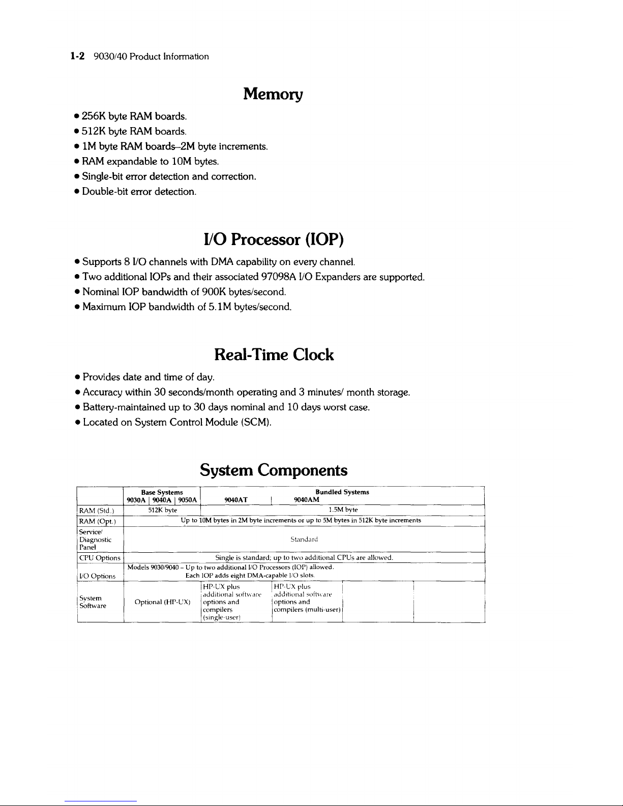
System
Components
Base Systems I
9030A I 9040A I 9050A
9040AT
I
Bundled Systems
9040AM
~RA
__
M~(S~td_.~)~
____
5~1~2K~by~te
____
~!L-
______________________
~I~.5~M_b~y~te
_________________________
_
RAM
(Op!.) Up to 10M bytes in
2M
byte increments
or
up
to
5M
bytes in SI2K byte increments
I
Servicel
Diagnostic
Panel
CPU
Options
liOOptions
I
'system
Software
I
Standard
Single is
standard;
up
to
two
additional CPUs are allowed.
Models
9030/9040 - Up to two additional
110
Processors (lOP) allowed.
Each
lOP
adds
eight DMA-capable 110 slots
I HP-CX plus ! HP-CX
plus
:
addlhonal
suftware
addlhonal
sufh\'are
Optional
(HP-UX) 1
options
and
I
options
and.
I
compilers I compIlers (multI-user) I
I (single-user)
9030/40 Product Information
1-3
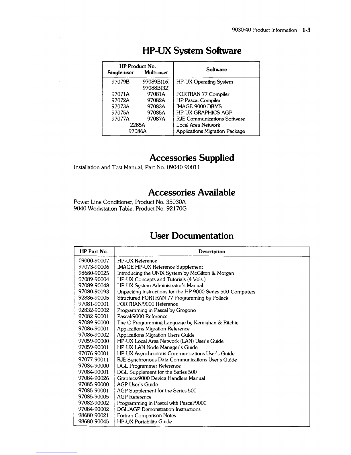
HP-UX System Software
HP Product No.
Single-user Multi-user
Software
97079B
97089B(16)
HP-UX Operating System
97088B(32)
97071A 97081A
FORTRAN
77 Compiler
97072A 97082A
HP
Pascal Compiler
97073A 97083A IMAGE-9000
DBMS
97075A
97085A
HP-UX GRAPHICS AGP
97077A 97087A
RJE Communications Software
2285A Local Area Network
97086A
Applications Migration Package
Accessories Supplied
Installation and Test Manual, Part
No.
09040-90011
Accessories Available
Power Line Conditioner, Product
No.
35030A
9040 Workstation Table,
Product
No.
92170G
User Documentation
HP Part No. Description
09000-90007
HP-UX
Reference
97073-90006
IMAGE
HP-UX Reference Supplement
98680-90025 Introducing the
UNIX
System by McGilton & Morgan
97089-90004 HP-UX Concepts
and
Tutorials (4 Vols.)
97089-90048 HP-UX System Administrator's Manual
97080-90093 Unpacking Instructions for the
HP
9000
Series
500
Computers
92836-90005 Structured FORTRAN 77 Programming by Pollack
97081-90001
FORTRAN/9000
Reference
92832-90002 Programming
in
Pascal by Grogono
97082-90001
PascaV9000
Reference
97089-90000
The C Programming Language by Kernighan & Ritchie
97086-90001 Applications Migration Reference
97086-90002 Applications Migration Users Guide
97059-90000 HP-UX Local Area Network
(LAN)
User's Guide
97059-90001 HP-UX
LAN
Node Manager's Guide
97076-90001
HP-UX
Asynchronous Communications User's Guide
97077-90011
RJE Synchronous Data Communications User's Guide
97084-90000 DGL Programmer Reference
97084-90001
DGL Supplement for the Series
500
97084-90026 Graphics/9000 Device Handlers Manual
97085-90000
AGP User's Guide
97085-90001
AGP Supplement for the Series
500
97085-90005
AGP Reference
97082-90002
Programming
in
Pascal with PascaV9000
97084-90002
DGLlAGP Demonstration Instructions
98680-90021
Fortran Comparison Notes
98680-90045
HP-UX
Portability Guide
1-4 9030/40 Product Information
HP
Part
No.
09040-80030
09040-90011
09040-90038
09040-90035
09000-90040
97060-90030
97062-90020
97098-90020
27132-91001
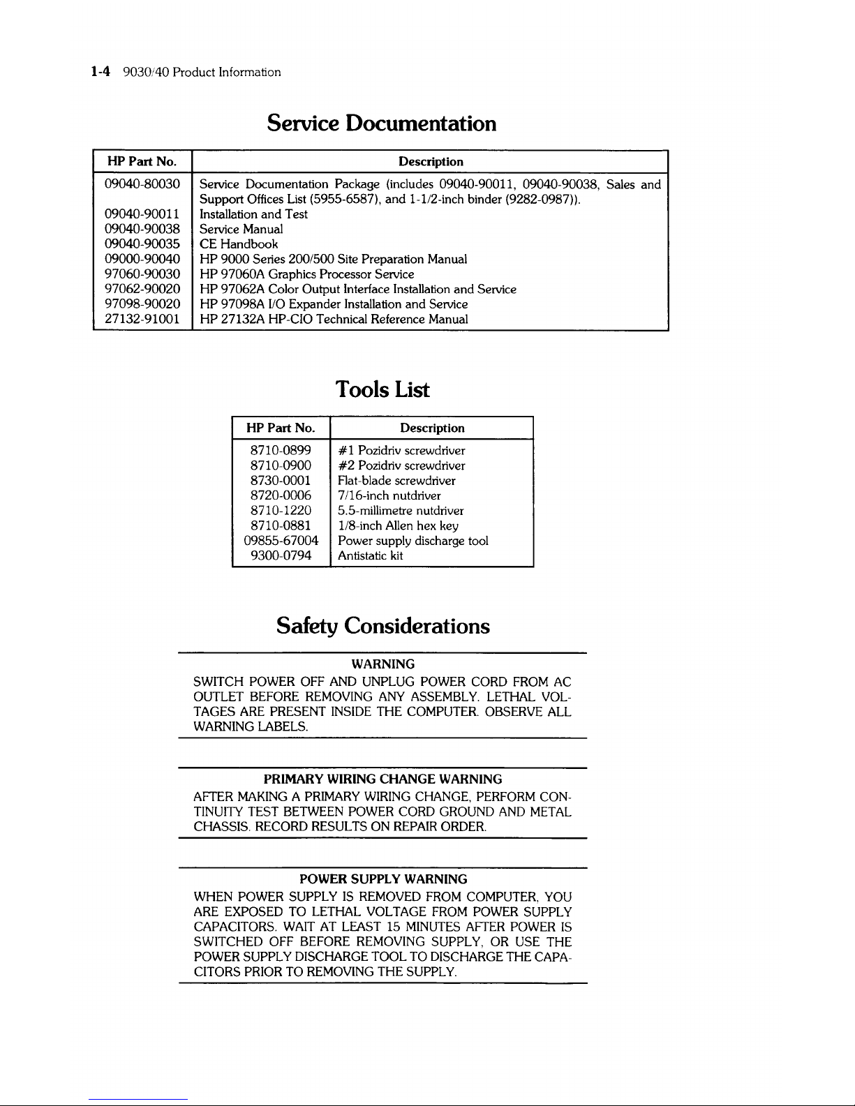
Service Documentation
Description
Service Documentation Package (includes 09040-90011, 09040-90038,
Sales
and
Support Offices List (5955-6587), and
l-lI2-inch
binder (9282-0987)).
Installation and Test
Service Manual
CE Handbook
HP
9000 Series 200/500 Site Preparation Manual
HP
97060A Graphics Processor Service
HP
97062A Color Output Interface Installation and Service
HP
97098A
110
Expander Installation and Service
HP
27132A HP-CIO Technical Reference Manual
Tools List
HP
Part No.
Description
8710-0899 # 1 Pozidriv screwdriver
8710-0900
#2
Pozidriv screwdriver
8730-0001
Rat-blade screwdriver
8720-0006 7/16-inch nutdriver
8710-1220 5.5-millimetre nutdriver
8710-0881
lI8-inch Allen hex key
09855-67004 Power supply discharge tool
9300-0794 Antistatic kit
Safety Considerations
WARNING
SWITCH POWER OFF AND UNPLUG POWER CORD FROM AC
OUTLET BEFORE REMOVING ANY ASSEMBLY. LETHAL VOLTAGES ARE PRESENT INSIDE THE COMPUTER. OBSERVE
ALL
WARNING LABELS.
PRIMARY
WIRING
CHANGE
WARNING
AFTER MAKING A PRIMARY WIRING CHANGE, PERFORM CONTINUITY TEST BETWEEN POWER CORD GROUND AND METAL
CHASSIS.
RECORD RESULTS ON REPAIR ORDER.
POWER
SUPPLY
WARNING
WHEN
POWER SUPPLY
IS
REMOVED FROM COMPUTER. YOU
ARE EXPOSED TO
LETHAL
VOLTAGE FROM POWER SUPPLY
CAPACITORS.
WAIT AT LEAST 15 MINUTES AFTER POWER
IS
SWITCHED OFF BEFORE REMOVING SUPPLY, OR USE THE
POWER SUPPLY DISCHARGE
TOOL
TO DISCHARGE THE CAPA-
CITORS PRIOR TO REMOVING THE SUPPLY.
2-1
Chapter 2
9030/40
Environmental/InstallationlPM
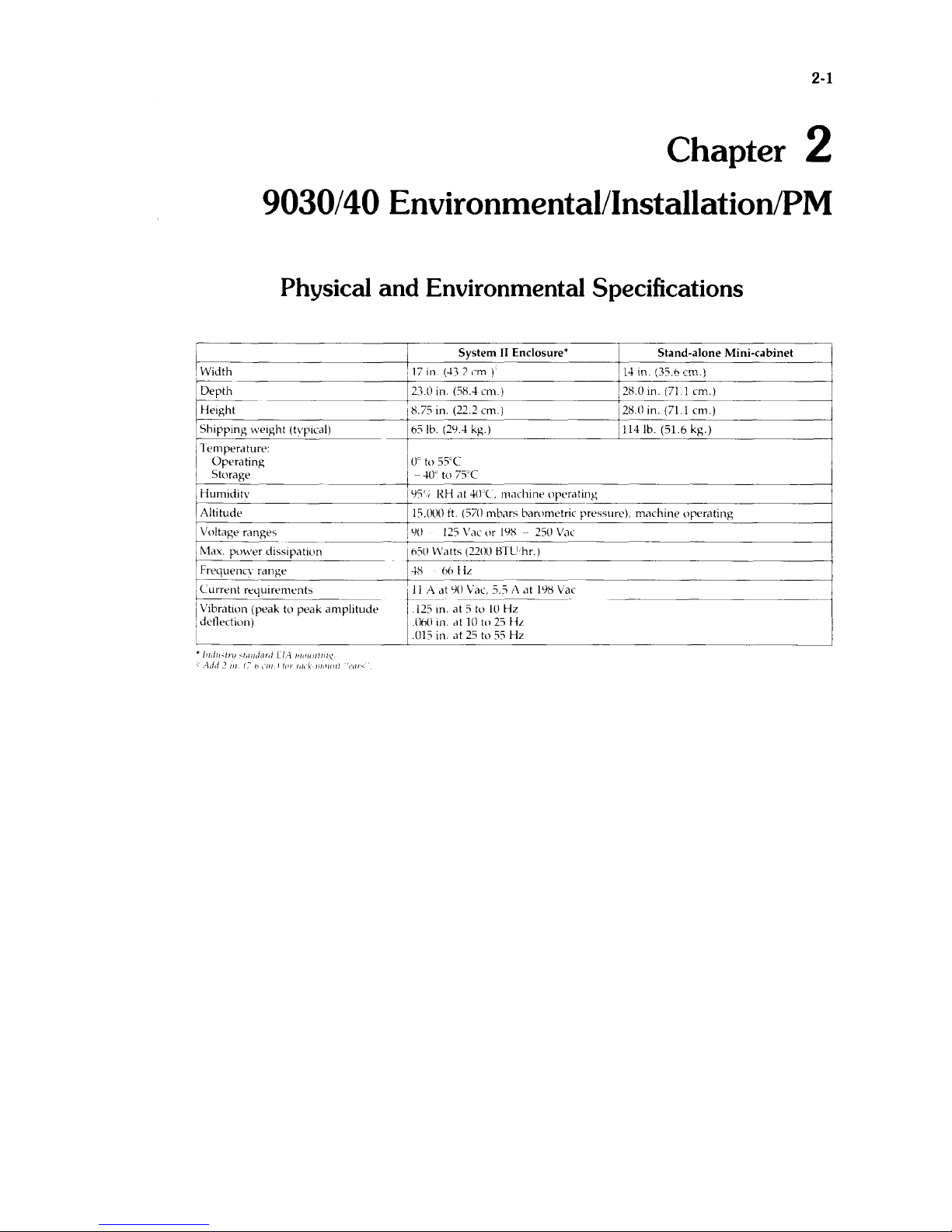
Physical and Environmental Specifications
I System
II
Enclosure' I Stand-alone Mini-cabinet
~
____________________
-+r_17
__
in
__
(~_1_)_C_m
__ ) _______________
tll~_~_"0;_nl·-n-(-.3-·(~7·-61-.Ll·n-··e1-m·)-.-)------------~
Depth
1230
in'.
(58 . .t
e~1.)
._0
Height
18.75 in. (22.2 em.) i 28.0 in. (71.1 em.)
rS_h~ip~p_in~g~\_\._ei~g_ht_(~t\~·p_ic_·a_I)
_______
165Ib.(2_9_ .
.t_k~g~')
________________
~!ll_l_4_lb_._(_51_._6_k~g-·)--------------4
Temperature:
Operating
I
Oc
to 55'C
Storage I - .to' to
75cC
I Humlliltv
195'.,
RH
at
.tWc. machIne operatll1g
Altitude 15.000
ft.
(570
mbars
barometric pressure),
machine
operating
Voltage
ranges
I Max.
power
dissipation
I Frequenev
range
Ie
I
L1rrent
requirements
I Vibration (peak to
peak
amplitude
IddlectJun)
:90
125
Vac
or
198 --250
Vac
I
h5U
Watts (2200
BTL!
hr.)
.t8
hh
ilL
I .
__
tl!_;\~'1t
90
vae,
J.J
A
at
198
Vae
i .125
In.
at 5 to
10
Hz
I
.llhO
in. at
10
io
25
HL
.015 in.
at
25
to
55
Hz
2-2 9030/40 Environmental/Installation/PM
Installation Procedure
1.
Unpack the computer.
2.
Position the computer. Leave about 6 inches of space at each side of computer (9030)
or
6
inches at back
(9040).
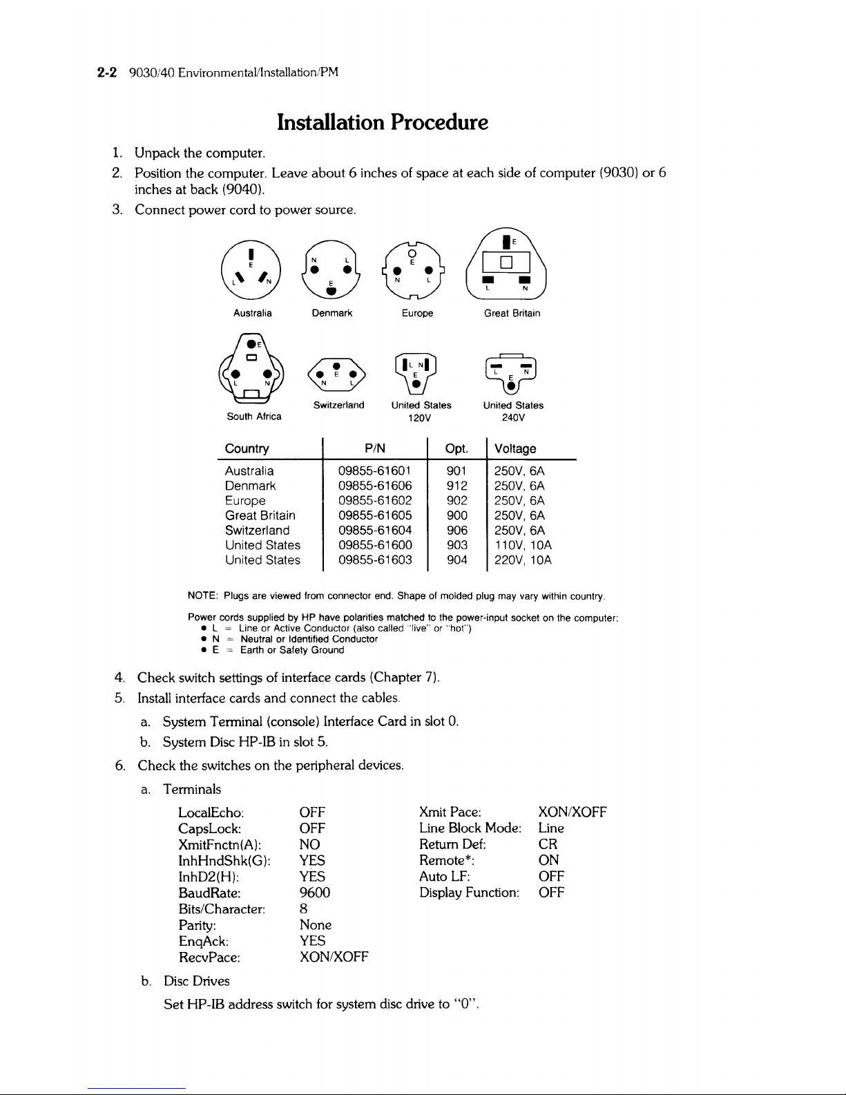
3.
Connect power cord to power source.
Q),
~
~
E
[JLJ
••
L N
Australia
South
Africa
Country
Australia
Denmark
Europe
Great Britain
Switzerland
United States
United States
Denmark
~
~
Europe
Switzerland
United States
120V
PIN
09855-61601
09855-61606
09855-61602
09855-61605
09855-61604
09855-61600
09855-61603
Opt.
901
912
902
900
906
903
904
Great Britain
Q
-
L N
E
•
United States
240V
Voltage
250V,6A
250V,6A
250V, 6A
250V, 6A
250V,6A
110V,10A
220V,10A
NOTE: Plugs are viewed from connector end. Shape of molded plug may vary within country.
Power cords supplied by HP have polarities matched
to
the power-input socket
on
the computer:
• L = Line or Active Conductor (also called "live"
or
"hot")
•
N = Neutral or Identified Conductor
• E = Earth or Safety Ground
4. Check switch settings of interface cards (Chapter
7).
5.
Install interface cards and connect the cables.
a.
System Terminal (console) Interface Card in slot
O.
b.
System
Disc
HP-IB
in
slot
5.
6.
Check the switches on the peripheral devices.
a.
Terminals
LocalEcho:
OFF
Xmit
Pace: XON/XOFF
CapsLock:
OFF
Line Block Mode: Line
XmitFnctn(A):
NO
Return
Def:
CR
InhHndShk(G):
YES
Remote*:
ON
InhD2(H): YES
Auto
LF:
OFF
BaudRate:
9600
Display Function:
OFF
Bits/Character: 8
Parity:
None
EnqAck:
YES
RecvPace:
XON/XOFF
b.
Disc
Drives
Set
HP-IB address switch for system disc drive to "0".
9030/40 EnvironmentalllnstallationlPM 2-3
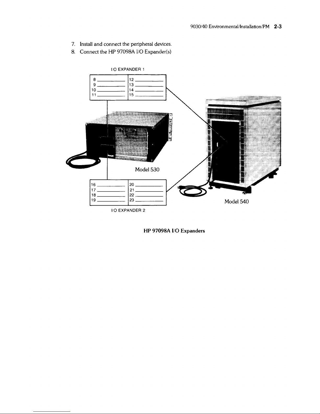
7.
Install and connect the peripheral devices.
8.
Connect the
HP
97098A
110
Expander(s)
I/O EXPANDER 1
8
____
_
12
____
_
9
____
_
13
____
_
10
____
_
14
____
_
11
____
_
15
____
_
16
____
_
20
____
_
17
____
_
21
____
_
18
____
_
22
____
_
19
____
_
23
____
_
Model
540
I/O EXPANDER 2
HP
97098A
1/0
Expanders

2-4
903040
Environmental;Installation
PM
Preventive Maintenance
There
are
no
scheduled
preventive
maintenance
procedures.
9020/9030/9040 Environmental/Installation/PM 2-5
Finstrate Installation
Instructions for HP -Qualified Personnel:
Start
on
page 2-6 (RAM/CPU), or 2-7 (lOP)
and
follow the instructions that apply to the installation
you are performing. For example,
if
you are installing a
2nd
lOP
in a 520
computer you would start
on
page 2-7,
and
perform
all
steps that begin with: (ALL),
(ALL
2nd
lOP),
(ALL
EXCEPT
520-3rd
lOP), (520), (520 ONL
Yl,
and
(520-2nd lOP).
ALL
RAM
and
CPU Instuctions start
on
2-6.
ALL
lOP Instructions start
on
2-7.
When completed with the installation of the finstrate, Insert the following pages
in
your CE
Hand-
book
(after page
2-4
of either the
9020
or
9030/9040
section).
2-6 9020/9030/9040 Environmental/Installation/PM
RAM/CPU Finstrate Installation
1.
(ALL)
TURN
THE
POWER OFF AND DISCONNECT THE POWER CORD.
2.
(520)
Open
the left door.
(530)
Remove
the
front panel.
(540)
Remove
the
front
bottom
panel.
3.
(530/540 ONLY)
From
the
front of the computer, remove the Radio Frequency Interference
(RFI)
shield by
loosening
the
six thumbscrews.
4.
(ALL)
Open
processor stack door.
5.
(ALL)
CAUTION
ELECTROSTATIC DISCHARGE DAMAGE CAN OCCUR IN THE
FOLLOWING
STEPS.
FOLLOW
THE PRECAUTIONS IN CHAPTER
4 OF
THE
SERVICE MANUAL.
DO
NOT
TOUCH
EDGE CONNECTOR OR FINSTRATE PLANE.
HOLD
FINSTRATE BY EJECTORS OR SIDE EDGES ONLY. HAND-
LING
FINSTRATE
INCORRECTLY
COULD
CAUSE
ELECTROSTATIC DISCHARGE DAMAGE.
WHEN
INSTALLING
FINSTRATE,
HOLD
BY EJECTORS AND MOVE AIR CONTROLLER
OUT
OF THE
WAY
WITH
THE SIDE EDGE OF THE FINSTRATE.
Install
the
finstrate
in
the
first
unoccupied slot from the bottom. DO NOT LEAVE EMPTY
SLOTS
BETWEEN FINSTRA TES.
6.
(ALL)
Close
the
processor stack door. Firmly tighten thumbscrews to prevent
RFI
radiation.
Replace
the
label that
is
used as a seal for the processor stack
door
(Part
Number
5180-5201).
7.
(530/540 ONLY)
Replace RFI shield.
8.
(520)
Close left door.
(530)
Replace front panel.
(540)
Replace
the
front
bottom
panel.
9.
(ALL)
Connect
power
cord
to
ac outlet.
9020/9030/9040 Environmental/Installation/PM 2-7
1.
(ALL)
lOP Finstrate Installation
WARNING
OBSERVE
ALL
WARNINGS
AND
SAFETY
PROCEDURES
IN
THE
COMPUTER
SERVICE
MANUAL.
LETHAL
VOLTAGES
ARE
PRE-
SENT
IN
THE
COMPUTER.
TURN THE POWER OFF
AND
DISCONNECT THE POWER CORD.
2.
(520 - 2nd lOP)
Remove the left door.
(520 -
3rd
lOP)
Open
the left door. Remove the
110
expander cable from the 1/0 EXPANDER 1 slot
on
the processor stack door
(if
connected).
(530)
Remove front panel.
(540)
Remove both front panels
and
flip-top cover.
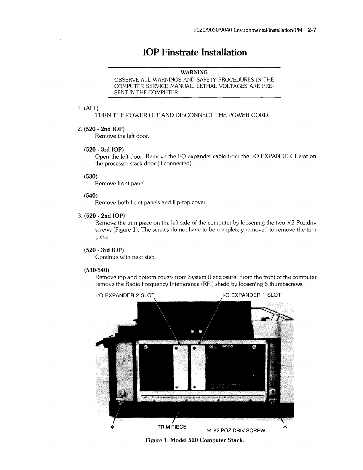
3.
(520 - 2nd lOP)
Remove the trim piece
on
the left side of the computer by loosening the two
#2
Pozidriv
screws (Figure
I).
The screws
do
not have to
be
completely removed to remove the trim
piece.
(520 -
3rd
lOP)
Continue with next step.
(530/540)
Remove top
and
bottom covers from System
II
enclosure. From the front of the
computer
remove the Radio Frequency Interference
(RFI)
shield by loosening 6 thumbscrews.
*
TRIM PIECE
*
#2
POZIDRIV SCREW
*
Figure
1.
Model
520
Computer
Stack.
2-8 902019030/9040 EnvironmentaLinstallation/
PM
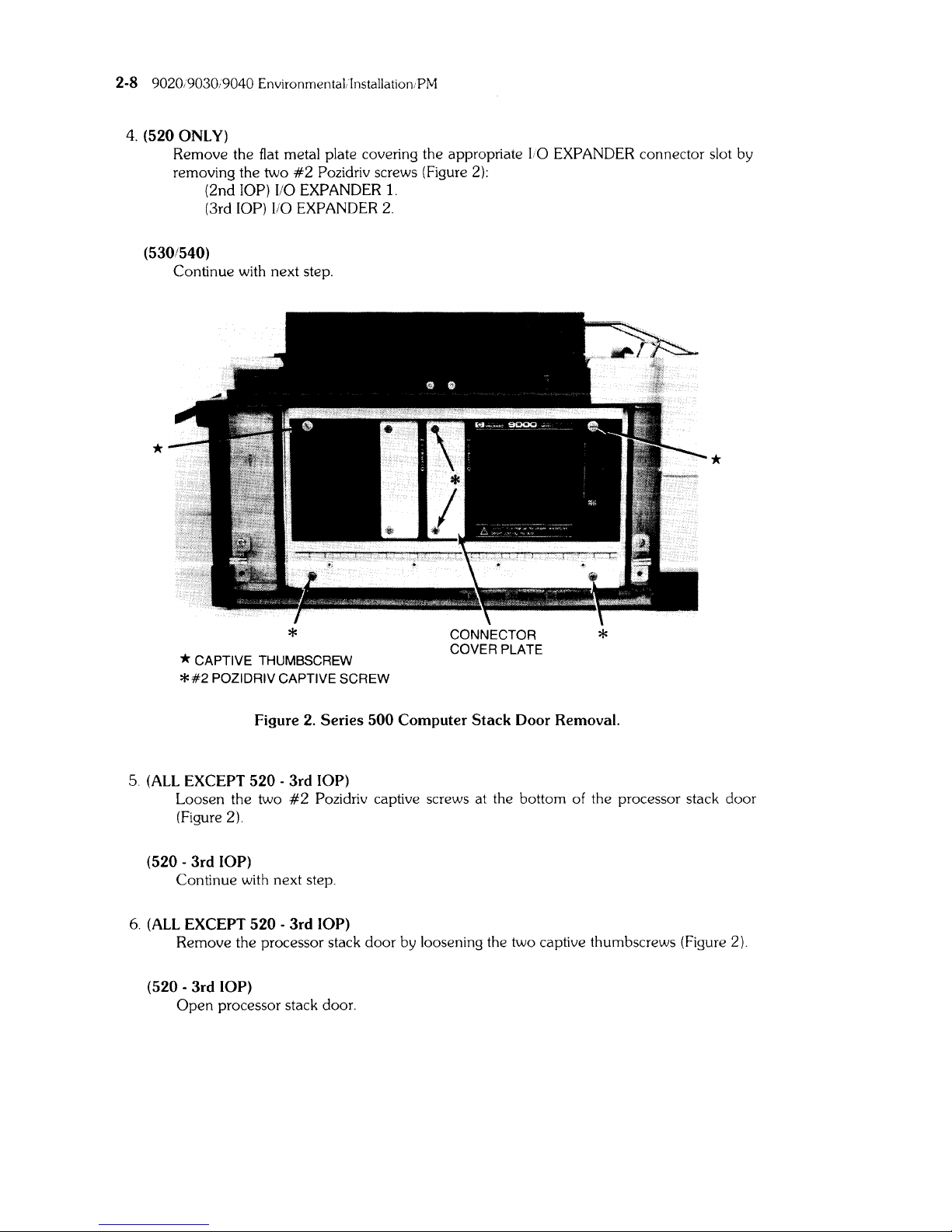
4.
(520 ONLY)
Remove the flat metal plate covering the appropriate 1,0 EXPANDER connector slot by
removing the two
#2
Pozidriv screws (Figure
2):
(2nd lOP)
110
EXPANDER
1.
(3rd lOP)
110
EXPANDER
2.
(530/540)
Continue with next step.
*
*
* CAPTIVE THUMBSCREW
*#2
POZIDRIV CAPTIVE SCREW
CONNECTOR
COVER
PLATE
*
Figure 2. Series
500
Computer Stack Door Removal.
5.
(ALL
EXCEPT
520
- 3rd lOP)
*
Loosen the two
#2
Pozidriv captive screws at the bottom of the processor stack door
(Figure 2).
(520 - 3rd lOP)
Continue with next step.
6.
(ALL
EXCEPT
520
- 3rd lOP)
Remove the processor stack
door
by loosening the two captive thumbscrews (Figure 2).
(520 - 3rd lOP)
Open
processor stack door.
9020/9030/9040 Environmental/Installation/PM 2-9
CAUTION
DO
NOT
TOUCH EDGE CONNECTOR
OR
FINSTRA
TE
PLANE.
HOLD
FINSTRA
TE
BY EJECTORS OR SIDE EDGES ONLY.
HANDLING FINSTRATE INCORRECTLY COULD CAUSE ELECTROSTATIC DISCHARGE DAMAGE.
WHEN
INSTALLING
FINSTRATE.
HOLD
BY EJECTORS AND MOVE AIR CONTROLLER OUT OF
THE WAY WITH THE SIDE EDGE OF THE FINSTRATE.
7.
(ALL -2nd
lOP)
Move
all
finstrates above slot 2 up one slot.
(ALL -3rd
lOP)
Move
all
finstrates above slot 3
up
one
slot (Slot 3
is
first
accessible finstrate without
removing door).
8.
(520 - ONLY)
Remove cable clamp from processor stack door by removing two # 1 Pozidriv screws.
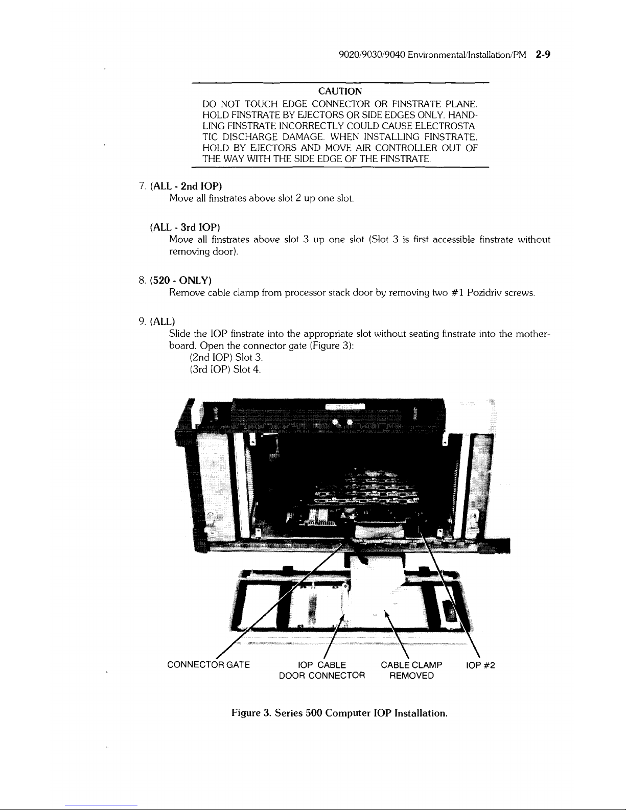
9.
(ALL)
Slide the lOP finstrate into the appropriate slot without seating
fin
strate into the mother-
board.
Open the connector gate (Figure 3):
(2nd
lOP) Slot
3.
(3rd lOP) Slot 4.
CONNECTOR GATE
lOP CABLE CABLE CLAMP
IOP#2
DOOR CONNECTOR REMOVED
Figure 3.
Series
500
Computer
lOP
Installation.
2-10
9020/9030/9040 Environmenta[ilnstallation·PM
10. (520)
Place lOP
cable door connector over studs on ends of appropriate
110
EXPANDER
connector
slot.
and
tighten connector to door
with
two nuts (Figure 3):
(2nd
lOP) 1/0 EXPANDER 1 slot.
(3rd
lOP)
\10
EXPANDER 2 slot.
(530/540)
Continue with step 12.
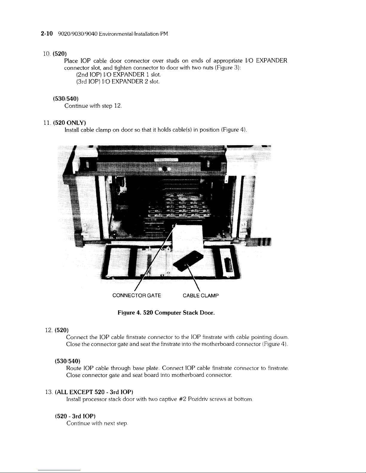
11.
(520 ONLY)
Install cable clamp on door so that
it
holds cable(s)
in
position (Figure 4).
CONNECTOR GATE
CABLE CLAMP
Figure 4.
520
Computer
Stack
Door.
12.
(520)
Connect the lOP cable finstrate connector to the lOP finstrate with cable pointing down.
Close the connector gate
and
seat the finstrate into the motherboard connector (Figure 4).
(530/540)
Route lOP cable through base plate. Connect lOP cable
fin
strate connector to finstrate.
Close connector gate
and
seat board into motherboard connector.
13.
(ALL
EXCEPT
520 -3rd
lOP)
Install processor stack door with two captive
#2
Pozidriv screws at bottom.
(520 -
3rd
lOP)
Continue with next step.
9020/9030/9040 Environmental/Installation/PM 2-11
14. (ALL)
Close processor stack door. Tighten thumbscrews to prevent Radio Frequency Interference
(RFl)
radiation. Replace the label that
is
used as a seal for the processor stack
door
(Part Number 5180-5201).
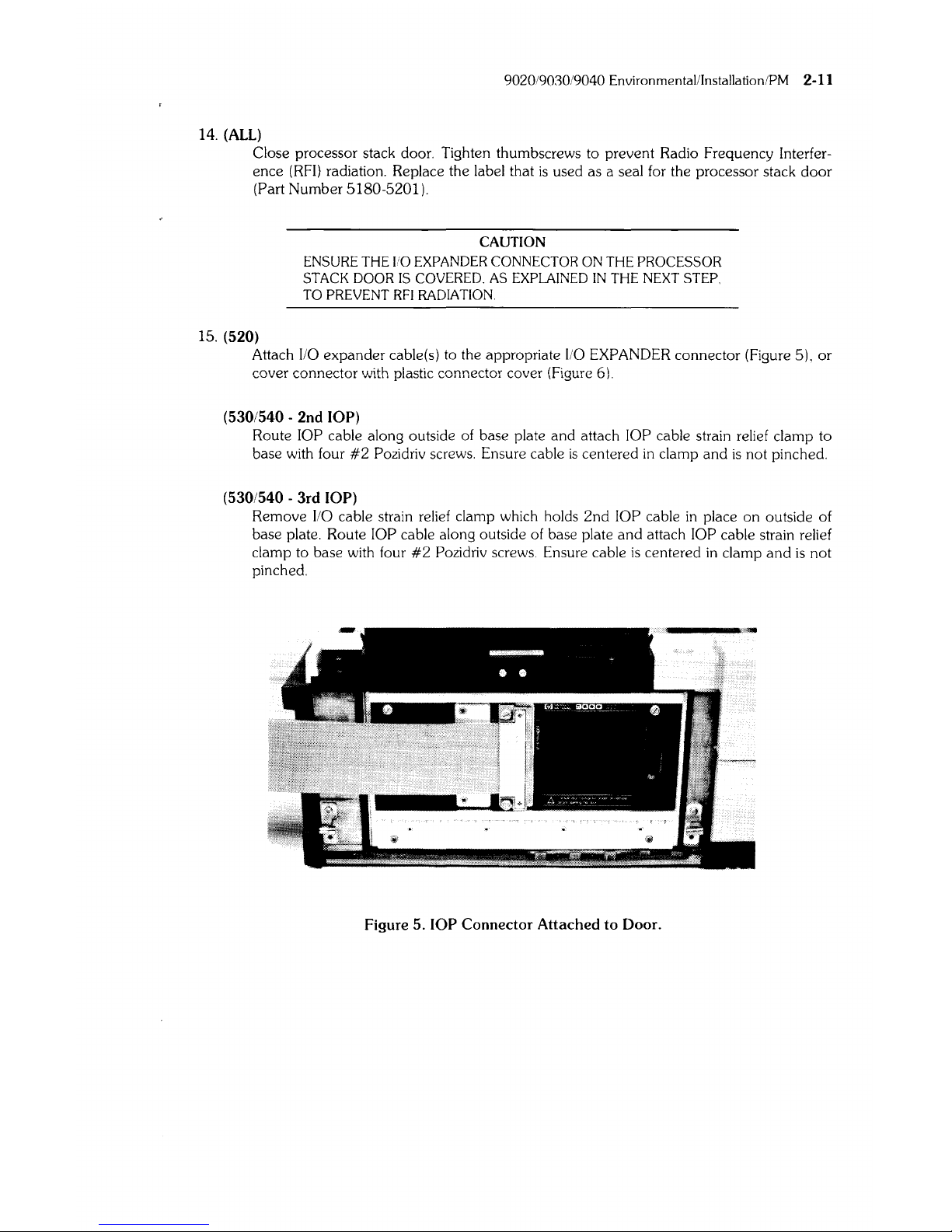
15. (520)
CAUTION
ENSURE
THE
I/O EXPANDER CONNECTOR ON
THE
PROCESSOR
STACK DOOR
IS
COVERED. AS EXPLAINED
IN
THE
NEXT
STEP
TO PREVENT
RFI
RADIATION.
Attach
I/O
expander cable(s) to the appropriate
I/O
EXPANDER connector (Figure 5),
or
cover connector with plastic connector cover (Figure 6).
(530/540 - 2nd lOP)
Route lOP cable along outside
of
base plate and attach lOP cable strain relief clamp to
base with four
#2
Pozidriv screws. Ensure cable
is
centered
in
clamp and
is
not pinched.
(530/540 - 3rd lOP)
Remove
I/O
cable strain relief clamp which holds
2nd
lOP cable
in
place on outside of
base plate. Route
lOP cable along outside of base plate and attach lOP cable strain relief
clamp to base with four
#2
Pozidriv screws. Ensure cable
is
centered
in
clamp
and
is
not
pinched.
M"_liK!a~
•
r
""
~,,~~
Y>~.
,",X«'N
Figure 5. lOP Connector Attached to Door.
2-12
902090309040
Environmental
Installation
PM
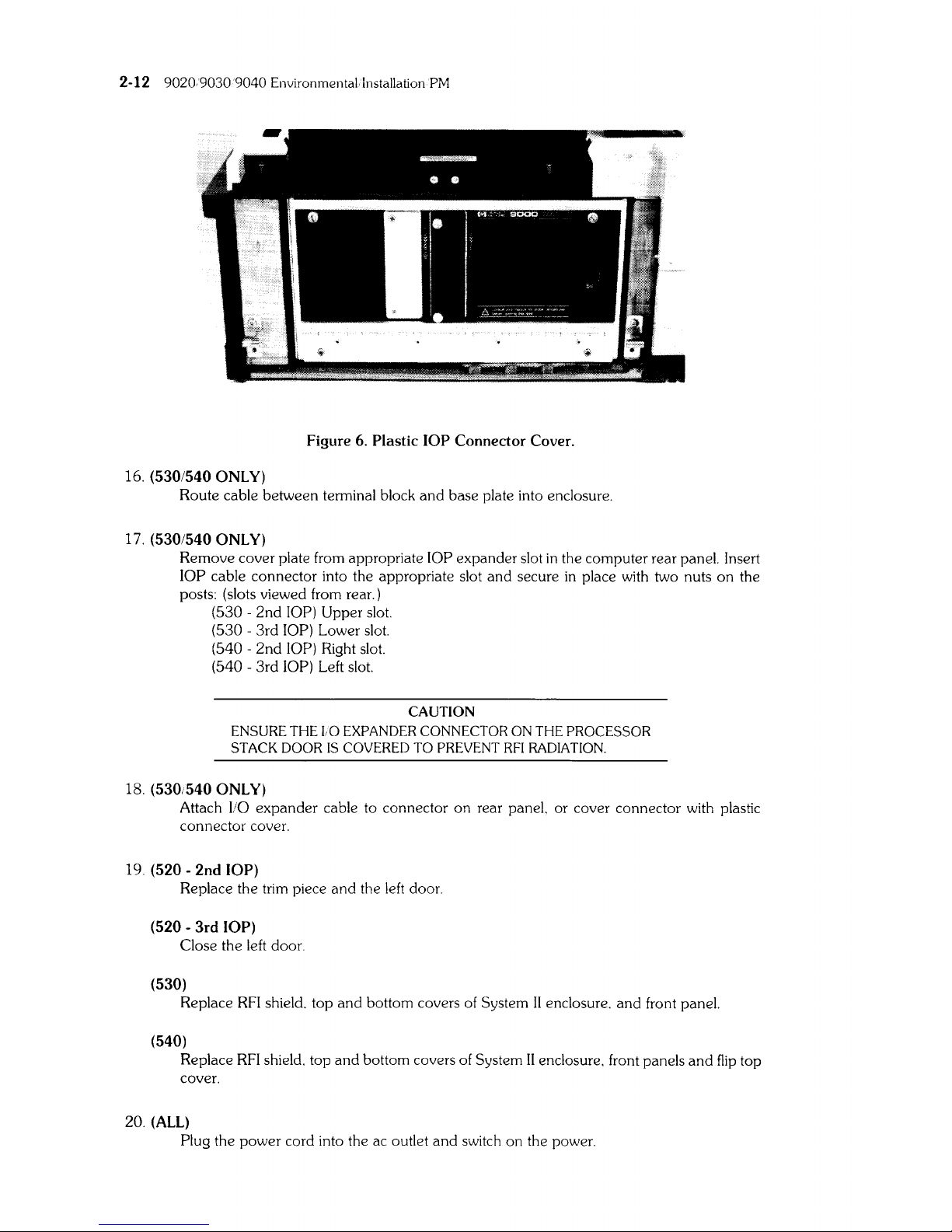
Figure 6. Plastic
lOP
Connector Cover.
16. (530/540
ONLY)
Route cable between terminal block
and
base plate into enclosure.
17.
(530/540
ONLY)
Remove cover plate from appropriate lOP expander slot
in
the computer rear panel. Insert
lOP cable connector into the appropriate slot
and
secure
in
place with two nuts
on
the
posts: (slots viewed from rear.)
(530 -
2nd
lOP) Upper slot.
(530 -
3rd
lOP) Lower slot.
(540 -
2nd
lOP) Right slot.
(540 -
3rd
lOP) Left slot.
CAUTION
ENSURE
THE
LO EXPANDER CONNECTOR ON THE PROCESSOR
STACK
DOOR
IS
COVERED
TO
PREVENT
RFI
RADIATION.
18. (530,540
ONLY)
Attach
110
expander
cable to connector
on
rear panel, or cover connector with plastic
connector cover.
19. (520 - 2nd lOP)
Replace the trim piece
and
the
left
door.
(520 -
3rd
lOP)
Close the left door.
(530)
Replace
RFI
shield. top
and
bottom covers of System
II
enclosure.
and
front panel.
(540)
Replace
RFI
shield. top
and
bottom covers of System
II
enclosure. front panels
and
flip
top
cover.
20. (ALL)
Plug the
power
cord into the ac outlet
and
switch on the power.

9020/9030/9040 Environmental/Installation/PM 2-13
512K RAM Board Installation Information
Instructions For HP-Qualified Personnel:
Follow the instructions that apply to the installation you are performing. For example,
if
you are
installing the
RAM
card
in
a 520 computer you would perform the steps that begin with: (ALL),
and
(520).
Load Board
Systems that are shipped from the Fort Collins Systems Division with 1 CPU. 1 lOP.
and
one
512K
Byte
RAM
Board,
will
also have a Load Board
in
the slot that
is
adjacent to the
RAM
board (top
occupied slot).
If
any other Finstrates, or
RAM,
is
added to this configuration, the Load Board must
be removed from the computer.
Any time the
Processor Stack configuration
is
reduced to 1 CPU, 1 lOP,
and
one
5l2K
Byte
RAM
Board, A Load Board (09855-66525)
is
required. Load Board (09855-66525)
is
a replaceable
part.
CE Handbook
When completed with the installation, insert this page
and
the following page
in
your CE
Handbook
(after page 2-12 of either the 9020 or 9030/9040 section).
Part Numbers
512K
Byte RAM (exchange)
(new)
Load Board
97047-69805
5061-6805
09855-66525
2-14 9020/9030/9040 Environmentalilnstallation/PM
512K Byte
RAM
Board Installation
1.
(ALL)
TURN THE POWER OFF
AND
DISCONNECT THE POWER CORD.
2.
(520)
Open
the left door.
(530)
Remove the front panel.
(540)
Remove the front bottom panel.
3.
(530/540
ONLY)
From the front of the computer, remove the Radio Frequency Interference
(RFI)
shield by
loosening the six thumbscrews.
4.
(ALL)
Open
processor stack door.
5.
(ALL)
CAUTION
ELECTROSTATIC
DISCHARGE
DAMAGE
CAN
OCCUR
IN
THE
FOLLOWING STEPS.
FOLLOW
THE
PRECAUTIONS
IN
CHAPTER
4
OF
THE
SERVICE
MANUAL.
DO
NOT
TOUCH
EDGE
CONNECTOR
OR
BOARD
PLANE.
HOLD
BOARD
BY
EJECTORS
OR
SIDE
EDGES
ONLY.
HANDLING
THE
RAM
BOARD
INCORRECTLY
COULD
CAUSE
ELECTROSTATIC
DISCHARGE
DAMAGE.
WHEN
INSTALLING
THE
RAM
BOARD.
HOLD
BY
EJECTORS
AND
MOVE
AIR
CONTROLLER
OUT
OF
THE
WAY
WITH
THE
SIDE
EDGE
OF
THE
BOARD.
Remove the Load Board (09855-66525) from the Processor Stack.
if
it
is
present
and
at least
one
RAM
board
is
installed. The load board
will
no
longer be required. It
is
the property of the
customer.
6.
(ALL)
Install the new
RAM
board
in
the
first
unoccupied slot from the bottom. DO NOT
LEAVE
EMPTY SLOTS BETWEEN BOARDS.
7.
(ALL)
Close the processor stack door. Firmly tighten thumbscrews to prevent
RFI
radiation. Replace
the label that
is
used as a seal for the processor stack door (Part Number 5180-5201).
8.
(530/540
ONLY)
Replace
RFI
shield.
9.
(520)
Close left door.
(530)
Replace front panel.
(540)
Replace the front bottom panel.
10.
(ALL)
Connect power cord to ac outlet.
9020/9030/9040 Environmental/Installation/PM 2-15
1 Megabyte RAM Board Installation
Instructions
Read the following information then follow the instructions that apply to the installation you
are
performing. For example, if you are installing the
RAM
Boards
in
a 520 computer you would
perform
all
steps that begin with:
(ALL),
and
(520).
RAM
Boards
1 Megabyte
RAM
Boards can only be installed
in
pairs. Any combination of 256K, 512K,
and
pairs
of 1 Megabyte boards can be used.
Load Board
If a system
is
shipped with 1 CPU, 1 lOP,
and
one 512K
RAM
Board,
it
will
also have a Load Board
(09855-66525)
in
the top occupied slot. When the 1 Megabyte
RAM
Boards are
added
to the
stack, the Load Board
is
no longer required
and
must be removed (assuming the 512K
RAM
board
remains
in
the system).
When the only
RAM
boards
in
the stack are 1 Megabyte
RAM
boards, a load board
is
required
if
there are six
or
less. The load board should be removed when there are more than six 1 Megabyte
RAM
boards
in
the stack,
or
if
there
is
a mixture of 256K, 512K,
and
1 Megabyte
RAM
boards
in
the
stack.
Any time the
Processor Stack configuration
is
changed so that
it
contains one of the
above
configurations, a Load Board
is
required. The load Board (09855-66525)
is
a replaceable part
in
spares. If the load board
is
used
it
must be
in
the top OCCUPIED slot of the Processor Stack. Do
not leave any empty slots between finstates or boards.
Boot Loader ROM
When the Processor Stack contains 1 Megabyte
RAM
Boards, Boot Loader ROM Rev. B (09020-
80001)
must be used,
and
UNIX
4.0
or
Basic 2.0 software must be used.
Boot Loader
ROM 09020-80000 can be used with
UNIX
4.0
or
Basic 2.0 (or any previous software
versions) as long as the stack
DOES NOT contain a 1 Megabyte
RAM
Board.
Boot Loader
ROM Rev. B (09020-80001) can be used with any
RAM
configuration but MUST use
UNIX
4.0 or BASIC 2.0 software (any earlier versions of software cannot be used with this
boot
loader).
Access Times
When the 1 Megabyte
RAM
Boards are installed
in
a computer, the access times
will
be slower. The
customer may notice this slower process time during operation.
System Integrity Test
The previous SFT tests (Part Number 09020-lO010 Rev. 2.0) are not compatible with the Basic 2.0
Operating System. The updated version of the SFT must be used with this operating system.
The
4.0 HP-UX Operating System contains the same System Functional Tests (SFT) as the pre-
vious
HP-UX. They are located
in
the
CEo
utilities dictionary.
2-16
9020/9030/9040 Environmental/Installation/PM
Part Numbers
1 Megabyte RAM Board (exchange)
(new)
Boot Loader
ROM *
Load Board
97046-69704
5061-7704
09020-80000
(Rev.A)
09020-80001 (Rev.B)
09855-66525
*
See
BOOT LOADER
ROM
on
the previous page
for
part number applicability. When ordenng
the
ROM,
the serial number and model number of the computer
must
be
given to the individual
taking the order.
CE Handbook
When completed with the installation, insert these pages
in
your CE Handbook (after page 2-14
oj
either the
9020
or 9030/9040 section).
RAM
Board Installation
1.
(ALL)
TURN THE POWER OFF
AND
DISCONNECT THE POWER CORD.
2.
(520)
Open
the left door.
(530)
Remove the front panel.
(540)
Remove both front panels and the fiiptop cover.
3.
(530/540 ONLY)
From the front of the computer, remove the Radio Frequency Interference
(RFI)
shield by
loosening the
six
thumbscrews.
4.
(ALL)
Open processor stack door.
5.
(ALL)
CAUTION
ELECTROSTATIC DISCHARGE DAMAGE CAN OCCUR IN THE
FOLLOWING
STEPS.
FOLLOW THE PRECAUTIONS
IN
CHAPTER
4 OF THE SERVICE MANUAL.
DO NOT TOUCH EDGE CONNECTOR
OR
BOARD PLANE.
HOLD
BOARD BY EJECTORS
OR
SIDE
EDGES
ONLY. HANDLING THE
RAM BOARD INCORRECTLY
COULD CAUSE ELECTROSTATIC
DISCHARGE DAMAGE. WHEN INSTALLING THE RAM BOARD.
HOLD
BY EJECTORS AND MOVE
AIR
CONTROLLER OUT
OF
THE WAY WITH THE SIDE EDGE
OF
THE BOARD.
Remove the Load Board (09855-66525) from the Processor Stack,
if
it
is
present.
6.
(ALL)
Install the
RAM
boards starting with the
first
unoccupied slot from the bottom. DO NOT
LEAVE
EMPTY SLOTS BETWEEN BOARDS.
If
a Load Board
is
required, install
it
in
the
next slot above the
RAM.
(See
"Load
Board"
in
the information at the front of the proce-
dure.)
7.
(ALL)
Close the processor stack door. Firmly tighten thumbscrews to prevent
RFI
radiation. Re-
place the label that
is
used as a seal
for
the processor stack door (Part Number 5180-5201).
9020/9030/9040 Environmental/Installation/PM 2-17
8.
(520)
Close the left side door.
(530/540)
Replace the
RFI
shield.
9.
(520)
Remove right side door.
(530/540)
Remove the top cover of the System
II
enclosure. The cover has
one
captive screw at the
back of the box. Loosen the screw
and
slide the cover back
and
away from the box.
10.
(530/540 ONLY)
Disconnect the ac module cable
and
the service module cable.
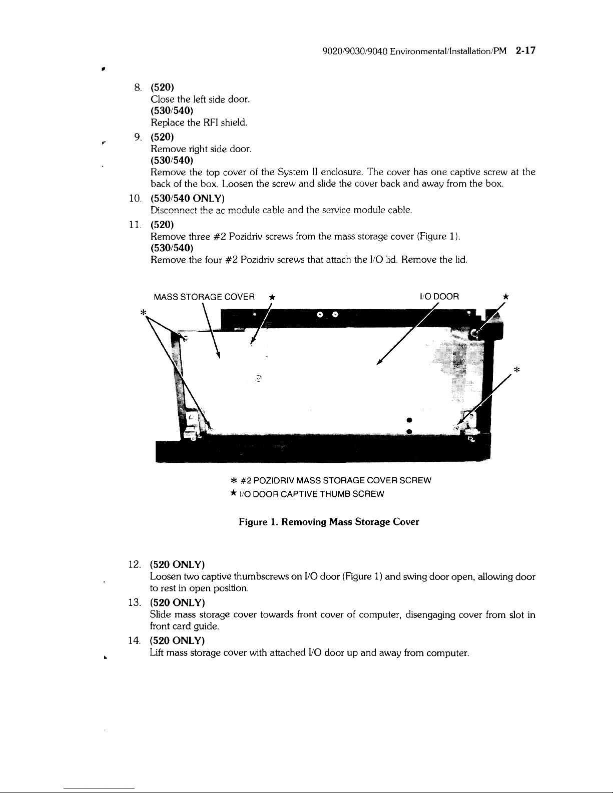
11.
(520)
Remove three
#2
Pozidriv screws from the mass storage cover (Figure
1).
(530/540)
Remove the four
#2
Pozidriv screws that attach the
110
lid.
Remove the
lid.
MASS STORAGE COVER *
1/0 DOOR
12.
(520 ONLY)
*
#2
POZIDRIV MASS STORAGE COVER SCREW
*
110
DOOR CAPTIVE THUMB SCREW
Figure
1.
Removing
Mass
Storage
Cover
*
*
Loosen two captive thumbscrews
on
I/O door (Figure
1)
and
swing door open, allowing
door
to rest
in
open
position.
13.
(520 ONLY)
Slide mass storage cover towards front cover of computer, disengaging cover from slot
in
front card
gUide.
14.
(520 ONLY)
Lift
mass storage cover with attached
110
door up and away from computer.
2-18 9020/9030/9040 Environmental/Installation/PM
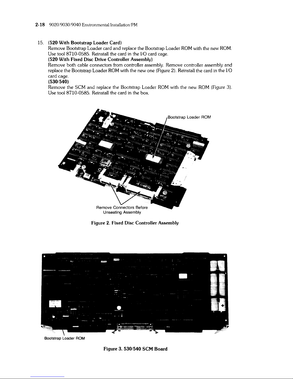
15.
(520 With
Bootstrap
Loader Card)
Remove Bootstrap Loader card and replace the Bootstrap Loader
ROM
with the new
ROM.
Use tool 8710-0585. Reinstall the card
in
the 1/0 card cage.
(520 With Fixed Disc Drive Controller Assembly)
Remove both cable connectors from controller assembly. Remove controller assembly and
replace the Bootstrap Loader
ROM
with the new one (Figure 2). Reinstall the card
in
the
110
card cage.
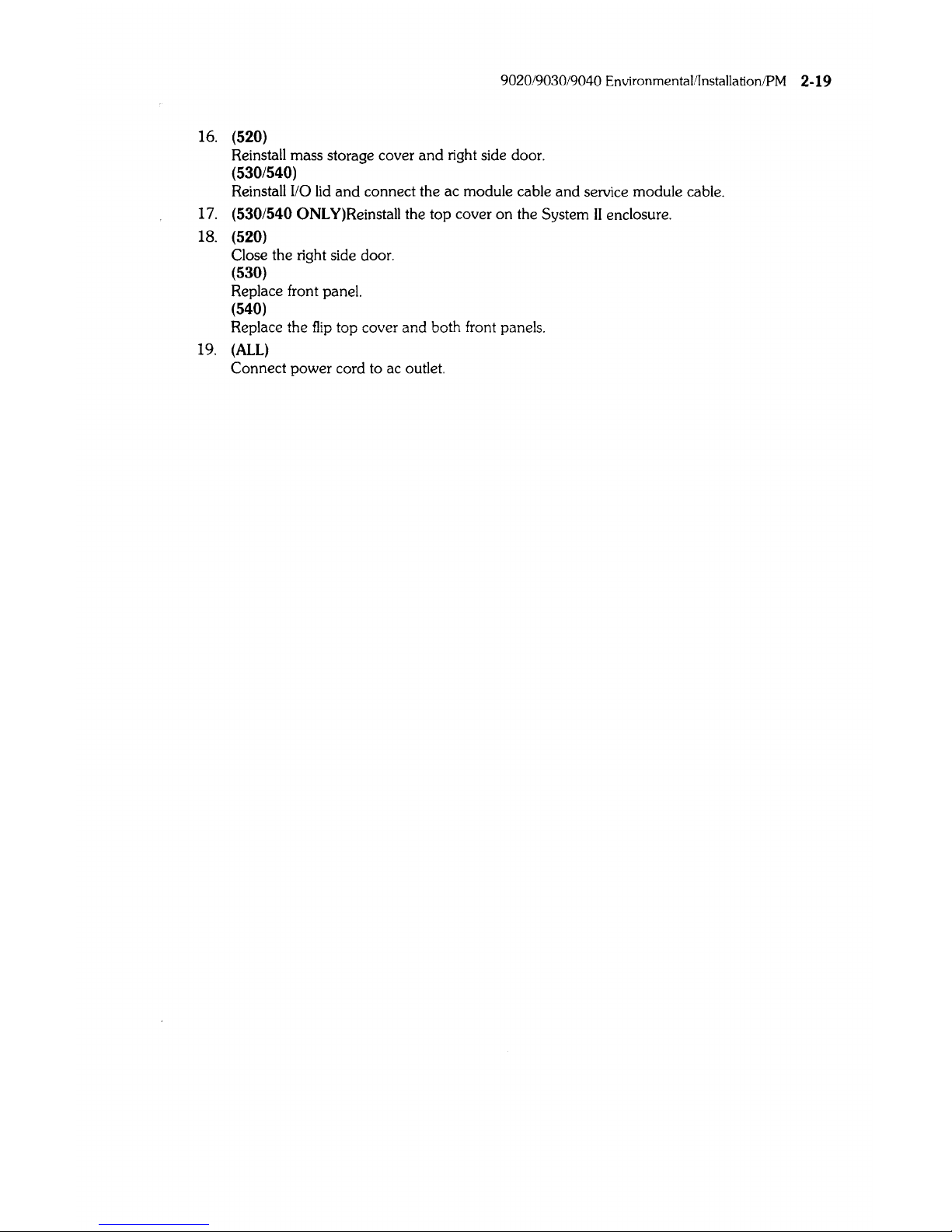
(530/540)
Remove the SCM
and
replace the Bootstrap Loader
ROM
with the new
ROM
(Figure 3).
Use tool 8710-0585. Reinstall the card
in
the box.
Figure 2. Fixed Disc Controller Assembly
Bootstrap Loader ROM
Figure 3. 530/540 SCM
Board
9020/9030/9040 Environmental/Installation/PM 2-19
16. (520)
Reinstall mass storage cover
and
right side door.
(530/540)
Reinstall
I/O
lid
and
connect the ac module cable and service module cable.
17. (530/540
ONLY)Reinstall
the top cover on the System
II
enclosure.
18.
(520)
Close the right side door.
(530)
Replace front panel.
(540)
Replace the
flip
top cover and both front panels.
19.
(ALL)
Connect power cord to ac outlet.

2-20 9020/9030/9040 Environmental/Installation/PM
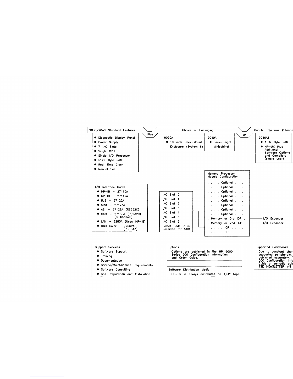
9030/9040
Standard Features
• Diagnostic Display Panel
•
Power Supply
•
7
I/O
Slots
• Single
CPU
• Single
I/O
Processor
• 512K Byte
RAM
•
Real
Time Clock
• Manual Set
I/O
Interface Cards
•
HP-IB
- 27110A
• GP-IO
-
27112A
•
RJE
-
27122A
•
SRM
- 27123A
•
ASI
-
27128A (RS232C)
•
MUX
- 27130A (RS232C)
(8
Channel)
•
LAN
- 2285A (Uses
HP-IB)
•
RGB
Color -97062A
(RS-343)
Support Services
• Software Support
•
Training
• Documentation
• Service/Maintainance Requirements
• Software Consulting
• Site
Preparation and Installation
Choice
of
Packaging
9030A 9040A
•
19 inch
Rack-Mount
•
Desk-Height
Enclosure (System II) Minicabinet
Memory
Processor
Module
Configuration
Optional
Optional
Optional
I/O
Slot
0
Optional
I/O
Slot 1
Optional
I/O
Slot
2
Optional
I/O
Slot
3
Optional
-
I/O
Slot 4
Optional
I/O
Slot 5
Memory
or
3rd
I/O
Slot
6
Memory 2nd
or
Select Code 7
is
"'"-
lOP
Reserved
for
SCM
CPU
Options
Options
are published in the
HP
9000
Series
500
Configuration Information
and Order Guide.
Software Distribution Media
lOP
lOP
HP-UX
is always distributed on
1/4"
tape.
Bundled Systems (Standa
9040AT
• 1.0M Byte
RAM
•
HP-UX
Plus
Additional
Software Options
and
Compilers
(single
user)
I/O
Expander
I/O
Expander
Supported
Peripherals
Due
to
constant
chan
supported
peripherals.
published separately.
l
500
Configuration Info
Guide
or
periodic pub
TSE
NEWSLETTER
will
 Loading...