

HP 9020A, 9020B, 9020C, 9020AS, 9020AT Handbook
HP
9000
Series
500
Computers
9020
CE Handbook
Part No. 09020-90035
E0485
Requires Binder No. 9282-0683
rhO-
HEWLETT
a!a111
PACKARD
Prtnted in U.S.A
Edition 1
April 1985
9020
CE Handbook
Note
This handbook
is
ONLY for the use of HP-qualified Service Personnel.
@ Copyright 1984, 1985, Hewlett-Packard Company
This document contains proprietary information which
is
protected by copyright.
All
rights are reserved. No part of this
document
may
be photocopied, reproduced or translated to another language without the prior written consent of
Hewlett-Packard Company. The information contained in this document is subject to change without notice.
Restricted Rights Legend
Use, duplication, or disclosure by the Government is subject to restrictions as set forth
in
paragraph (b)(3)(B)
of
the
Rights in Technical Data and Software clause
in
DAR 7-104.9(a)
© Copyright 1980, Bell Telephone Laboratories, Inc.
© Copyright
1979,1980,
The Regents of the University of California.
This software and documentation is based
in
part on the Fourth Berkeley Software Distribution under license from the
Regents of the University of California
@ Copyright 1979, The Regents of the University of Colorado, a body corporate
This document has been reproduced and modified with the permission of the Regents of the University
of
Colorado, a
body corporate
Hewlett-Packard Company
3404 East Harmony Road, Fort Collins, Colorado 80525
Product Information
II
Environmental/Installation/PM
E
Configuration
I
Troubleshooting
II
Diagnostics
I
Adjustments
I
Peripherals
I
Replaceable
Parts
I
Diagrams
I
Reference
iii
Service Notes
a
ii
Printing History
New editions
of
this
manual
will
incorporate
all
material
updated
since
the
previous edition.
Update
packages may
be
issued between editions
and
contain replacement
and
additional pages
to
be
merged
into
the
manual
by
the
user.
Each
updated
page will
be
indicated
by a revision
date
at
the
bottom
of
the
page. A vertical
bar
in
the
margin indicates
the
changes on each page.
Note
that
pages which
are
rearranged
due
to
changes on a previous page
are
not
considered
revised.
The
manual
printing
date
and
part
number
indicate
its
current
edition.
The
printing
date
changes
when
a new
edition
is
printed. (Minor corrections
and
updates
which
are
incorporated
at
reprint
do
not
cause
the
date
to
change.)
The
manual
part
number
changes when extensive
technical changes
are
incorporated.
August
1984 ...
Edition
1.
Replaced
the
9020
CD
Handbook, 09020-90039,
and
all
updates.
January
1984 ...
Edition 1 with
updates.
April 1985 ...
Edition 1 with
update
merged.
July
1985 ...
Update.
NOTICE
The information contained
in
this document
is
subject to change without notice.
HEWLETT-PACKARD MAKES
NO
WARRANTY
OF
ANY KIND WITH REGARD
TO
THIS MANUAL. INCLUDING. BUT NOT
LIMITED TO,
THE IMPLIED WARRANTIES
OF
MERCHANTABILITY AND FITNESS
FOR
A PARTICULAR PURPOSE. Hewlett-
Packard shall
not be liable for errors contained herein or direct, indirect, special, incidental or consequential damages
in
connection with the furnishing, performance, or use of this material.
WARRANTY
A copy
of
the specific warranty terms applicable to your Hewlett-Packard product and replacement parts can be obtained from
your
local Sales and Service Office
09020·90035, rev: 7'85
9020
Product
Information 1-1
~
________________
~II~al~~1
_ 9020
Product
Infonnation
.
Product Information
Features
• 32-bit CPU and
full
32-bit internal and external data paths.
• Add-on performance with multiple CPUs.
•
Up
to 10 Mbytes
RAM.
•
36
Mbyte/second memory processor bus.
• Four internal HP-CIO slots expandable to 20.
•
Virtual memory with
500
Mbyte address space.
• Single-user or multi-user system.
• HP-UX Operating System with FORTRAN 77, Pascal, or C languages; or BASIC Language
System.
•
Error correcting
and
self-healing memory.
• High-performance interactive graphics.
• Broad range of peripherals.
Central Processor Unit
• 32-bit single chip composed of 450,000 transistors.
• Direct address range of
500
Mbytes.
• Supports
IEEE
Floating Point Format.
• Instruction set of
230
operation codes.
• 18
MHz
clock rate with micro-instruction cycle time of
55
ns and memory cycle time of
110
ns.
• Typical execution times:
(CPU without math chips)
Load register from memory
........................................
550
nanoseconds
64-bit floating point multiply
......................................
10.34 microseconds
32-bit integer multiply
............................................
2.92 microseconds
64-bit floating point add
..........................................
5.94
microseconds
(CPU with math chips)
Floating point math chips decrease program time by performing math functions
in
hardware
chips. Improvement: 1.4 times faster (overall). Twice as fast on
BID
program.
Memory
.256
Kbyte
RAM
finstrates, 512K byte polystrates, or
1M
byte polystrates.
•
RAM
memory expandable to 2.5 Mbytes.
• Single-bit error detection
and
correction.
• Double-bit error detection.
I/O Processor
• Supports 8
110
channels with
DMA
capability on every channel.
• Two additional lOPs
and
their associated 97098A
110
Expanders are supported.
• Nominal lOP bandwidth of
900
Kbytes/second.
• Maximum lOP bandwidth of 5.1 Mbytes/second.
09020·90035, rev.llB5
1-2
9020
Product
Information
Real Time Clock
• Provides date
and
time of day.
• Accuracy to within 2 minutes/month within
O°C
to 45°C.
•
Battery-maintained up to
30
days nominal and 10 days worst case.
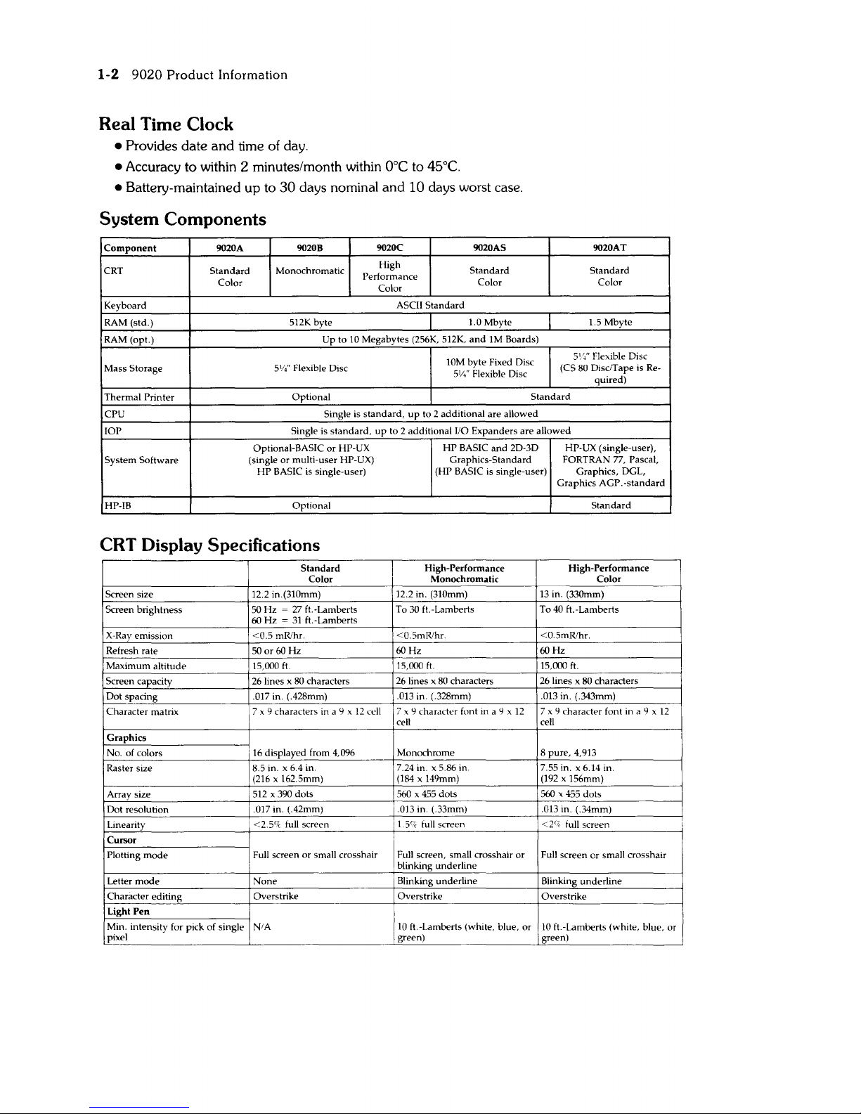
System Components
Component
9020A
9020B 9020C
9020AS 9020AT
CRT
Standard
Monochromatic
High
Standard
Standard
Color
Performance
Color
Color
Color
Keyboard
ASCII
Standard
RAM (std.)
S12K
byte 1.0 Mbyte 1.S Mbyte
RAM (opt.)
Up to
10
Megabytes (256K,
S12K,
and
1M
Boards)
10M byte Fixed Disc
5
1
/;'
Flexible Disc
Mass
Storage
5W'
Flexible Disc (CS
80
Disc/Tape is Re-
5'/4' Flexible Disc
quired)
Thermal
Printer Optional
Standard
CPU
Single
is
standard,
up
to 2 additional are allowed
lOP
Single is
standard,
up
to 2 additional 1/0 Expanders are allowed
Optional-BASIC
or
HP-UX
HP
BASIC
and
2D-3D
HP-UX (single-user),
System Software
(single or multi-user HP-UX) Graphics-Standard
FORTRAN
77,
Pascal,
HP
BASIC
is
Single-user) (HP BASIC is single-user)
Graphics, DGL,
Graphics AGP.-standard
HP-IB Optional
Standard
CRT
Display Specifications
Screen size
Screen brightness
X-Ray emission
Refresh rate
Maximum altitude
Screen capacity
Dot spacing
Character matrix
Graphics
No. of colors
Raster size
Array size
Dot resolution
Linearity
Cursor
Plotting
mode
Letter
mode
Character editing
Light
Pen
Standard
Color
High-Performance
Monochromatic
12.2 in.(31Omm) 12.2 in.
(31Omm)
50
Hz = 27
ft.-Lamberts To
30
ft.-Lamberts
60
Hz
=
31
ft.-Lamberts
<0.5
mRlhr. <0.5mRlhr.
50
or
60
Hz
60
Hz
15,000
ft
15,000
ft.
26
lines x 80 characters
26
lines x
80
characters
.017 in. (.428mm) .013 in. (.328mm)
7
x 9 characters in a 9 x 12 cell 7 x 9 character font in a 9 x
12
cell
16
displayed from 4,096
8.5 in. x 6.4 in.
(216
x 162.5mm)
512 x 390
dots
.017 in. (.42mm)
<2.5'"
full screen
Monochrome
7.24 in. x 5.86 in.
(184
x 149mm)
560
x
455
dots
.013 in. (.33mm)
1.5'7,
full screen
High-Performance
Color
13
in.
(33Omm)
To
40
ft.-Lamberts
<0.5mRlhr.
60Hz
15,000
ft.
26
lines x 80 characters
.013 in. (.343mm)
7
x 9 character font in a 9 x
12
cell
8 pure, 4,913
7.55 in. x 6.14 in.
(192
x 156mm)
560
x
455
dots
.013 in. (.34mm)
<2'"
iull screen
Full screen or small crosshair Full screen, small crosshair or Full screen or small crosshair
blinking underline
None
Blinking underline Blinking underline
Overstrike Overstrike Overstrike
Min. intensity for pick of single
NI
A
pixel
10
ft.-Lamberts (white, blue,
or
10
ft.-Lamberts (white, blue,
or
green) green)
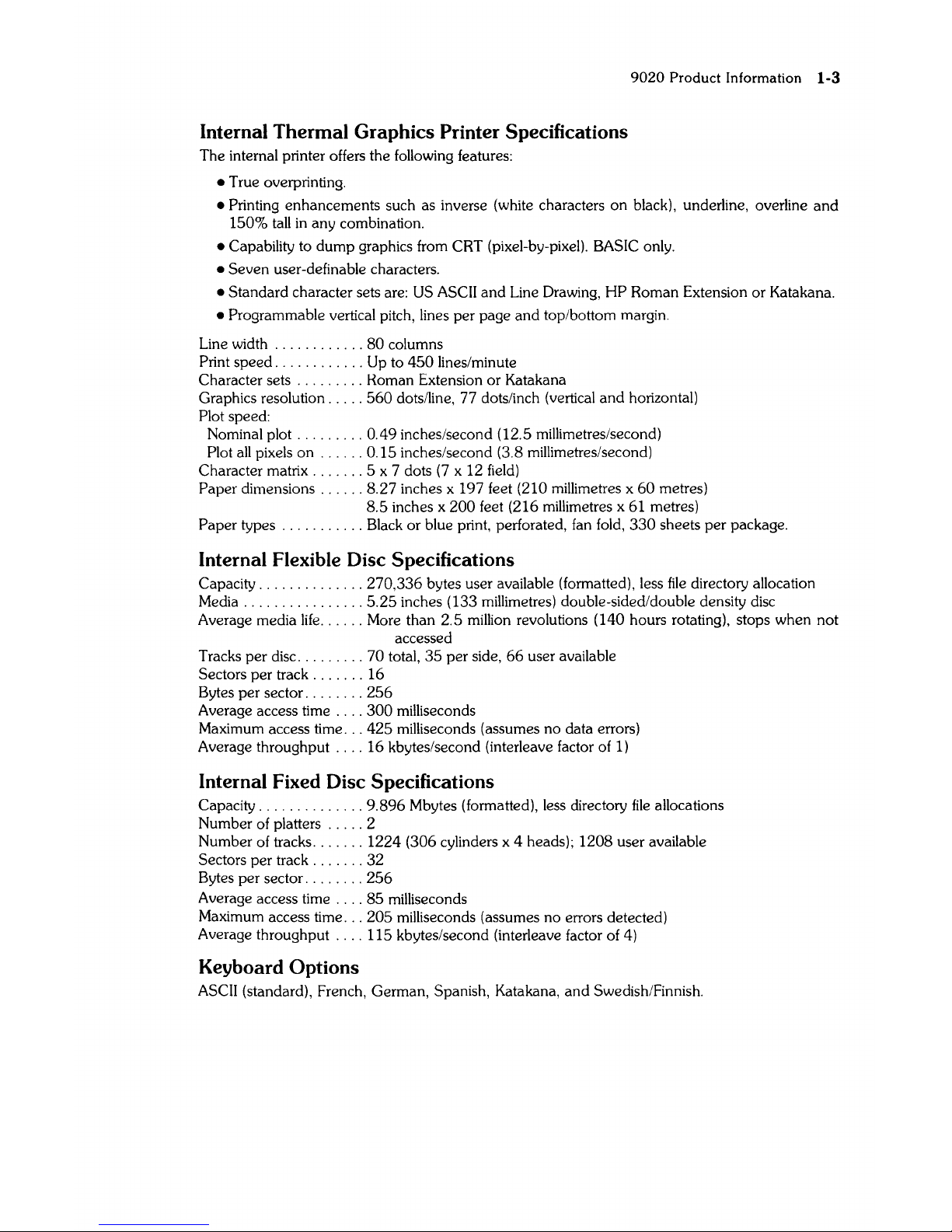
Internal Thermal Graphics Printer Specifications
The internal printer offers the following features:
• True overprinting.
9020
Product
Information 1-3
• Printing enhancements such as inverse (white characters
on
black), underline, overline
and
150%
tall
in
any combination.
• Capability to dump graphics from CRT (pixel-by-pixel). BASIC only.
• Seven user-definable characters.
• Standard character sets are:
US
ASCII
and
Line Drawing, HP Roman Extension or Katakana.
• Programmable vertical pitch, lines per page
and
top/bottom margin.
Line width
............
80
columns
Print speed
............
Up to
450
lines/minute
Character sets
.........
Homan Extension or Katakana
Graphics resolution
.....
560
dots/line, 77 dots/inch (vertical and horizontal)
Plot speed:
Nominal plot
.........
0.49 inches/second (12.5 millimetres/second)
Plot
all
pixels on
......
0.15 inches/second (3.8 millimetres/second)
Character matrix
.......
5 x 7 dots
(7
x 12
field)
Paper dimensions
......
8.27 inches x 197 feet (210 millimetres x
60
metres)
8.5
inches x
200
feet (216 millimetres x 61 metres)
Paper types
...........
Black or blue print, perforated,
fan
fold,
330
sheets per package.
Internal Flexible
Disc
Specifications
Capacity
..............
270,336 bytes user available (formatted), less
file
directory allocation
Media
................
5.25
inches (133 millimetres) double-sided/double density disc
Average media
life
......
More than 2.5 million revolutions (140 hours rotating), stops when not
accessed
Tracks per disc
.........
70 total,
35
per side,
66
user available
Sectors per track
.......
16
Bytes per sector
........
256
Average access time
....
300
milliseconds
Maximum access time
...
425
milliseconds (assumes no data errors)
Average throughput
....
16 kbytes/second (interleave factor of
1)
Internal Fixed
Disc
Specifications
Capacity
..............
9.896 Mbytes (formatted), less directory
file
allocations
Number of platters
.....
2
Number of tracks
.......
1224 (306 cylinders x 4 heads); 1208 user available
Sectors per track
.......
32
Bytes per sector
........
256
Average access time
....
85
milliseconds
Maximum access time
...
205
milliseconds (assumes no errors detected)
Average throughput
....
115 kbytes/second (interleave factor of 4)
Keyboard Options
ASCII (standard), French, German, Spanish, Katakana,
and
Swedish/Finnish.
1-4
9020
Product
Information
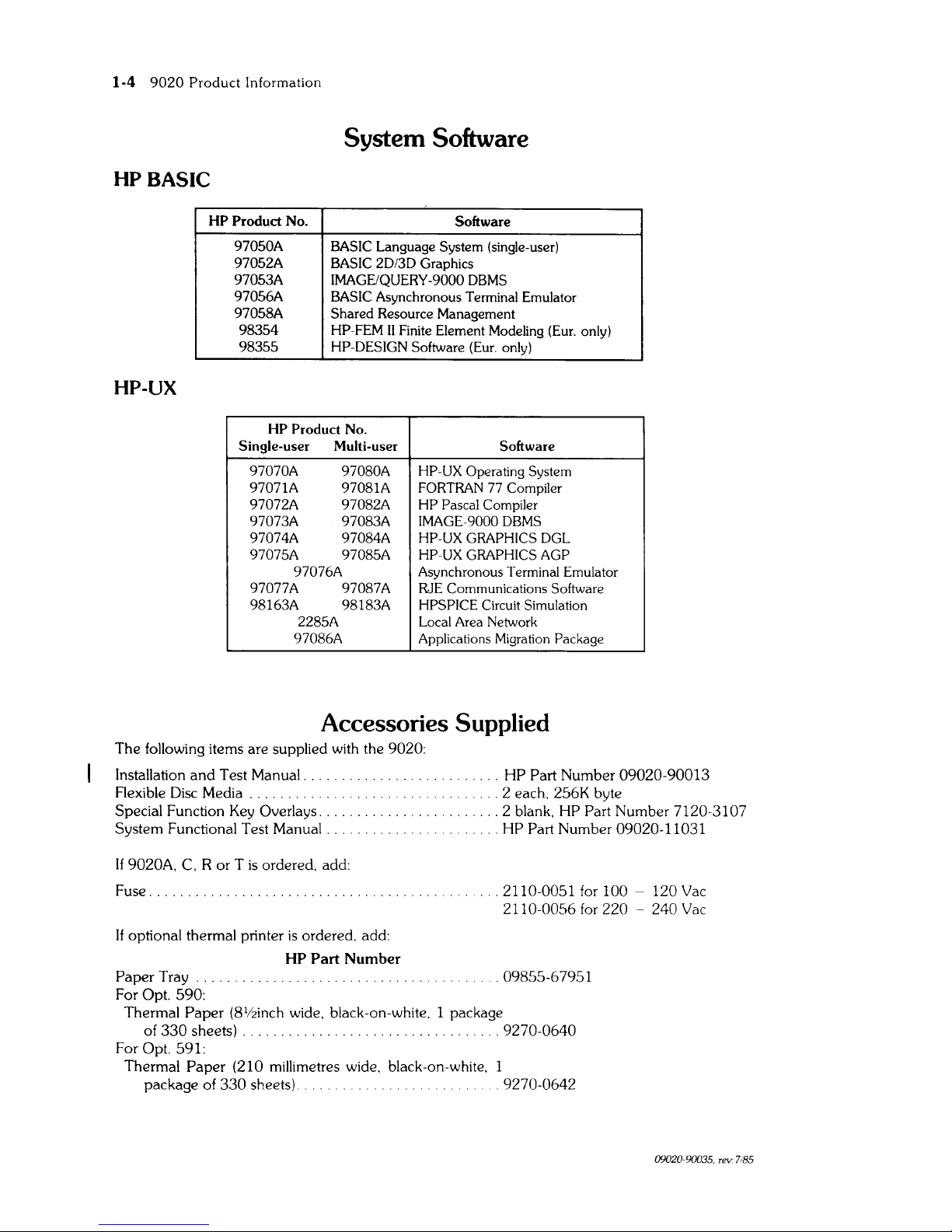
System Software
HP
BASIC
HP Product No.
Software
97050A
BASIC Language System (single-user)
97052A BASIC
20/30
Graphics
97053A IMAGE/QUERY-9000 DBMS
97056A
BASIC Asynchronous Terminal Emulator
97058A
Shared
Resource Management
98354
HP-FEM
II
Finite Element Modeling (Eur. only)
98355
HP-DESIGN Software (Eur. only)
HP-UX
HP
Product
No.
Single-user
Multi-user Software
97070A
97080A
HP-UX Operating System
97071A 97081A FORTRAN 77 Compiler
97072A 97082A HP Pascal Compiler
97073A 97083A IMAGE-9000 DBMS
97074A 97084A HP-UX GRAPHICS DGL
97075A 97085A HP-UX GRAPHICS AGP
97076A
Asynchronous Terminal Emulator
97077A 97087A RJE Communications Software
98163A 98183A
HPSPICE Circuit Simulation
2285A Local Area Network
97086A Applications Migration Package
Accessories Supplied
The following items are supplied with the 9020:
Installation
and
Test Manual. .
.......................
HP Part Number 09020-90013
Flexible
Disc
Media . . . . . . . 2 each. 256K byte
Special Function
Key
Overlays. .
.......
2 blank, HP Part Number 7120-3107
System Functional Test Manual. .
...................
HP Part Number 09020-11031
If 9020A,
C,
R or T
is
ordered. add:
Fuse. .
.2110-0051
for
100 - 120
Vac
2110-0056
for
220 - 240
Vac
If optional thermal printer
is
ordered. add:
HP Part
Number
Paper
Tray.
. . . . . . . . . .
.........
09855-67951
For
Opt. 590:
Thermal Paper
(81/2inch wide. black-an-white. 1 package
of
330
sheets) . .
.9270-0640
For Opt. 591:
Thermal
Paper (210 millimetres wide. black-an-white. 1
package of
330
sheets). . . 9270-0642
09020-90035. rev. 7/85
9020
Product
Information
1-5
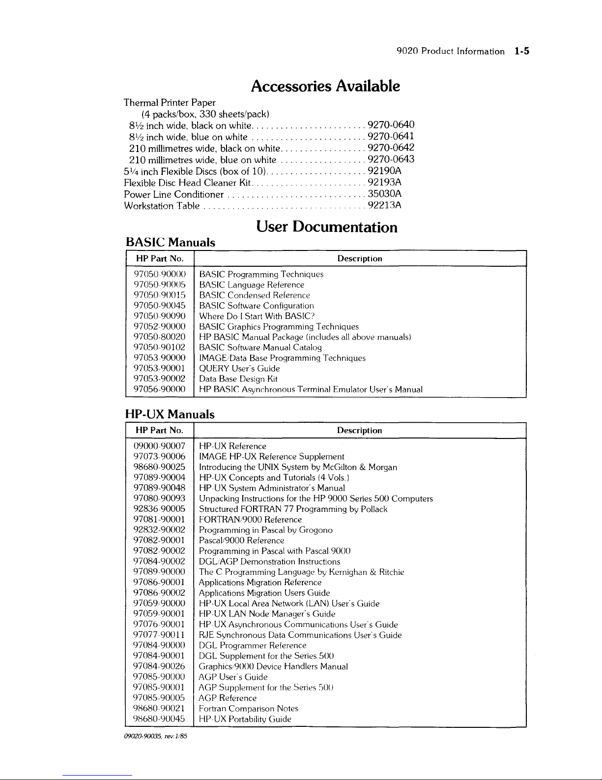
Accessories Available
Thermal Printer Paper
(4 packs/box,
330
sheets/pack)
81f2
inch wide, black
on
white, , , , , , , , , , , , , , , , , , , , , , , , 9270-0640
81f2
inch wide. blue on
white,
, , , , , , , , , , , , , , , , , , , , , , , 9270-0641
210
millimetres wide, black on white, , , , , , ,
,9270-0642
210
millimetres wide, blue
on
white,
, , , , , , , ,
,9270-0643
51J4
inch Flexible Discs (box of 10), , , , ,
,92190A
Flexible
Disc
Head Cleaner
Kit,
' , 92193A
Power Line Conditioner '
, 35030A
Workstation
Table,
' , , , , , , , , , , ,
,92213A
User Documentation
BASIC Manuals
HP
Part
No, Description
970S0-90000 BASIC Programming Techniques
970S09000S
BASIC
Language Reference
970S09001S
BASIC
Condensed Reference
970S0-9004S BASIC Software Configuration
970S0-90090 Where
Do
I Start
With
BASIC?
970S2-90000
BASIC
Graphics Programming Techniques
970S0-80020
HP BASIC
Manual Package (includes
all
above manuals)
970S0-90102
BASIC
Software. Manual Catalog
970S390000
IMAGE/Data Base Programming Techniques
970S3-90001
QUERY User's
Guide
970S3-90002
Data Base Design
Kit
970S6-90000 HP
BASIC':
Asynchronous Terminal Emulator User's Manual
HP-UX Manuals
HP
Part
No. Description
09000-90007 HP-UX Reference
97073-90006
IMAGE
HP-UX Reference Supplement
98680-9002S
Introducing the
UNIX
System by McGilton & Morgan
97089-90004 HP-UX Concepts and Tutorials
(4
Vols,)
97089-90048 HP-UX System Administrator's Manual
97080-90093 Unpacking Instructions
for
the HP
9000
Series
SOO
Computers
92836-9000S
Structured FORTRAN 77 Programming
by
Pollack
97081-90001
FORTRAN/9000
Reference
92832-90002
Programming
in
Pascal
by
Grogono
97082-90001
Pascal/9000
Reference
97082-90002 Programming
in
Pascal
with
Pascal
9000
97084-90002
DGLAGP
Demonstration Instructions
97089-90000
The C Programming Language by Kernighan & Ritchie
97086-90001 Applications Migration Reference
97086-90002 Applications Migration Users Guide
970S9-90000 HP-UX Local Area Network
(LAN)
User's Guide
970S9-90001
HP-UX
LAN
Node Manager's Guide
97076-90001
HP-UX
Asynchronous Communications User's Guide
97077-90011
RJE Synchronous Data Communications User's Guide
97084-90000
DGL Programmer Reference
97084-90001
DGL Supplement
for
the Series
SOO
97084-90026 Graphics;9000 Device Handlers Manual
9708S-90000 AGP User's Guide
9708S-9000 1 AGP Supplement
for
the Series
SO()
9708S-9000S
AGP
Reference
98680-90021
Fortran Comparison Notes
98680-9004S
HP-UX
Portability Guide
09020-90035, rev,
JIBS
1-6
9020
Product
Information
HP
Part
No.
09020-80038
09020-90013
09020-90037
09020-90035
09000-90040
97060-90030
97062-90020
97098-90020
27132-91001
09020-11031
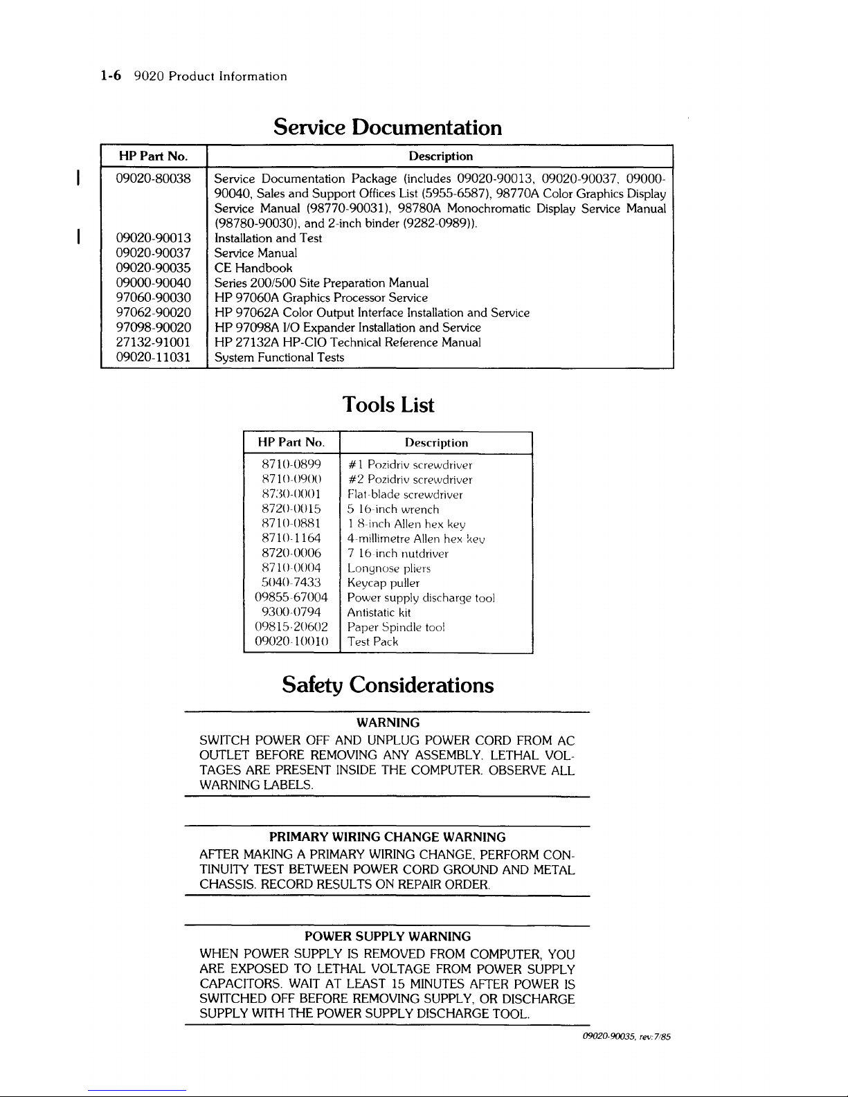
Service Documentation
Description
Service Documentation Package (includes
09020-90013, 09020-90037, 09000-
90040,
Sales
and Support Offices List (5955-6587), 98770A Color Graphics Display
Service Manual (98770-90031), 98780A Monochromatic Display Service Manual
(98780-90030), and 2-inch binder (9282-0989)).
Installation and Test
Service Manual
CE Handbook
Series
200/500 Site Preparation Manual
HP
97060A Graphics Processor Service
HP
97062A Color Output Interface Installation and Service
HP
97098A
110
Expander Installation and Service
HP
27132A HP-CIO Technical Reference Manual
System Functional
Tests
Tools
List
HP Part No.
Description
8710-0899
# 1 Pozidriv screwdriver
8710-()90()
#2
Pozidriv screwdriver
H730-()OOl
Flat-blade screwdriver
8720-00lS
S 16-inch wrench
8710-0881
1 Hinch Allen hex key
8710-1164
4-millimetre Allen hex kev
8720-0006
7 16-inch nutdriver
87100004
Longnose pliers
5()407433
Keycap puller
0985567004
Power supply discharge tool
9300-0794
Antistatic
kit
09815-20602
Paper
Spindle tool
0902010010
Test Pack
Safety Considerations
WARNING
SWITCH POWER OFF AND UNPLUG POWER CORD FROM AC
OUTLET BEFORE REMOVING ANY ASSEMBLY.
LETHAL
VOL-
TAGES ARE PRESENT INSIDE THE COMPUTER. OBSERVE
ALL
WARNING LABELS.
PRIMARY
WIRING
CHANGE
WARNING
AFTER MAKING A PRIMARY WIRING CHANGE. PERFORM CON-
TINUITY TEST BETWEEN POWER CORD GROUND AND METAL
CHASSIS. RECORD RESULTS ON REPAIR ORDER.
POWER SUPPLY
WARNING
WHEN
POWER SUPPLY
IS
REMOVED FROM COMPUTER, YOU
ARE EXPOSED
TO
LETHAL
VOLTAGE FROM POWER SUPPLY
CAPACITORS.
WAIT AT LEAST 15 MINUTES AFTER POWER
IS
SWITCHED OFF BEFORE REMOVING SUPPLY, OR DISCHARGE
SUPPLY WITH THE POWER SUPPLY DISCHARGE TOOL.
09020-90035. rev:7/85

9020 Environmental/Installation/PM 2-1
I
I~
9020
EnvironmentalllnstallationIPM
[::=D
Environmental
Width
..................................
2l.
75 inches (55.2 centimetres)
Depth
..................................
29
inches (73.6 centimetres)
Height
.................................
24.5 inches (62.2 centimetres)
Net Weight:
9020A
...............................
137 pounds (62.1 killograms)
9020B
...............................
121 pounds (55 killograms)
9020C
...............................
163 pounds (74 killograms)
Shipping Weight:
9020A
...............................
168 pounds (76.2 killograms)
9020B
...............................
152 pounds (69 killograms)
9020C
...............................
194 pounds (88 killograms)
Temperature:
Operating
............................
10° to 40°C
(with
disc media)
Storage
..............................
- 40° to 75°C (flexible disc media excluded)
Slew Rate
(lO-Mbyte Winchester
.........
10°C per hour
Humidity
...............................
20-80%
RH
non-condensing (maximum wet bulb,
25.5°), machine operating
Altitude
................................
15,000
feet (570
mbars
barometric pressure),
machine operating
Voltages
................................
90-125
Vac
or 189-250 Vac
Line Frequency Range
...................
48-66
Hz
Current Requirements
....................
12.0 A at 108 Vac
8.0
A at 198 Vac
15.0 A at 90
Vac
(Japan)
Power Dissipation
........................
850
Wats (2900 BTU/hr.)
Vibration (peak-to-peak amplitude deflection)
0.125 inches at 5 to 10
Hz
0.060 inches at 10 to
25
Hz
0.015 inches at
25
to
55
Hz
2-2
9020
Environmental/Installation/PM
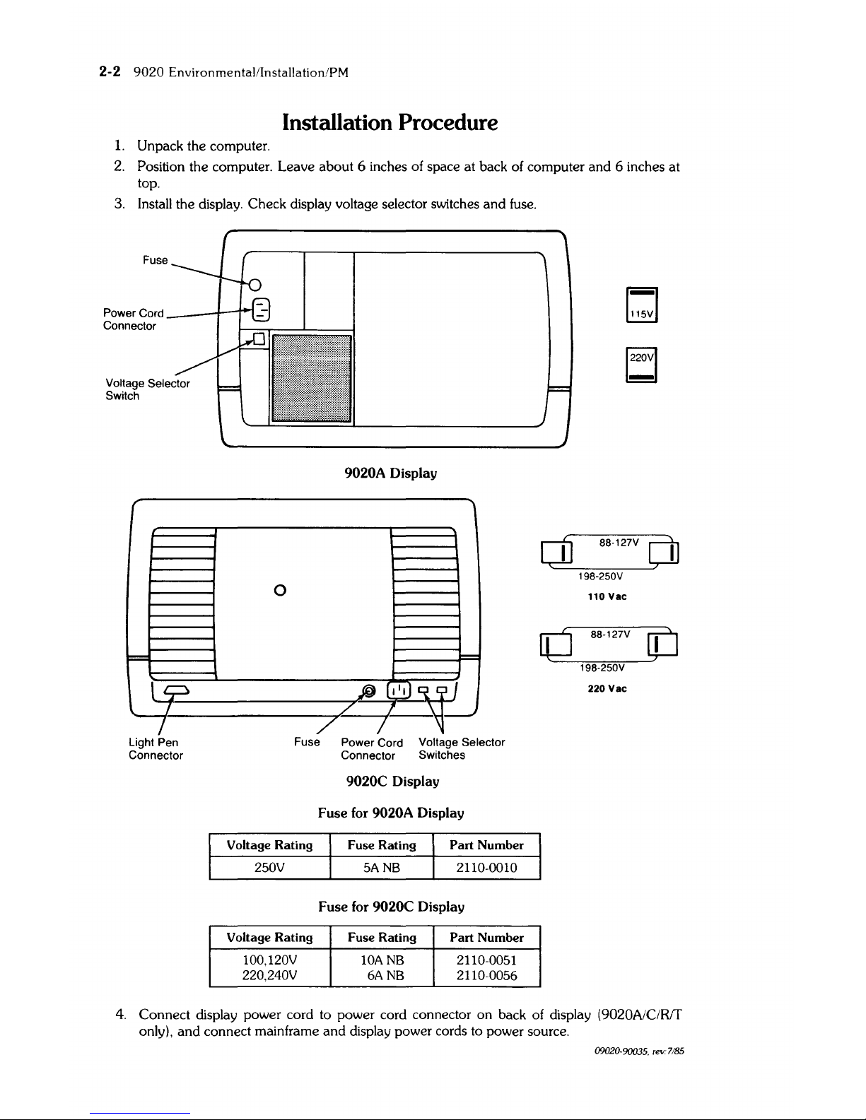
Installation Procedure
1.
Unpack the computer.
2.
Position the computer. Leave about 6 inches of space at back of computer and 6 inches at
top.
3.
Install the display. Check display voltage selector switches and fuse.
Fuse
Power Cord
Connector
r
""=
l
ll?
I
/
Light Pen
Connector
9020A Display
"'
0
t::=
.@(I~
/'
,
/ /
Fuse Power Cord Voltage Selector
Connector Switches
9020C Display
Fuse for 9020A Display
Voltage Rating
Fuse Rating
Part
Number
250V
5ANB
2110-0010
Fuse for 9020C Display
Voltage Rating Fuse Rating
Part Number
100, 120V
lOANB 2110-0051
220,240V
6ANB 2110-0056
dJ
88-127V
dJ
198-250V
110
Vac
0
88-127V
[jj
198-250V
220
Vac
4. Connect display power cord to power cord connector
on
back of display (9020A/C/Rf[
only),
and
connect mainframe
and
display power cords to power source.
09020-90035, rev: 7/85
9020 Environmental/Installation/PM 2-3
0)
\~
~]
~
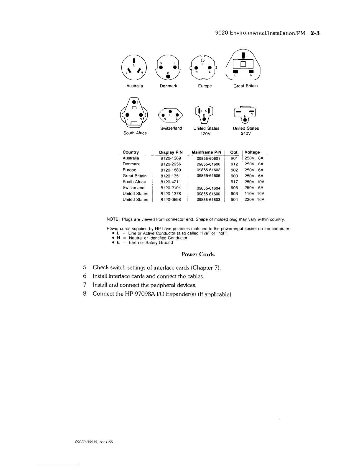
Australia Denmark Europe Great Britain
@
W
Q
L N
0
N L
•
Switzerland
United States United States
South Africa
120V
240V
Country
Display
PIN
Mainframe
PIN
Opt.
Voltage
Australia
8120-1369
09855-60601
901
250V. 6A
Denmark
8120-2956
09855-61606 912
250V. 6A
Europe
8120-1689
09855-61602
902
250V.
6A
Great Britain
8120-1351
09855-61605
900
250V.
6A
South Africa 8120-4211 917
250V. 10A
Switzerland 8120-2104
I
09855-61604
I
906
250V.
6A
United States 8120-1378
09855-61600
903
110V, 10A
United States
8120-0698
09855-61603 904
220V,
10A
NOTE: Plugs
are viewed from connector end. Shape of molded plug may vary within country
Power cords
supplied by HP have polarities matched
to
the power-Input socket on the computer:
• L Line or Active Conductor (also called "live" or "hot")
• N Neutral or Identified Conductor
• E = Earth or Safety Ground
Power
Cords
5. Check switch settings of interface cards (Chapter
7).
6.
Install interface cards
and
connect the cables.
7.
Install
and
connect the peripheral devices.
8.
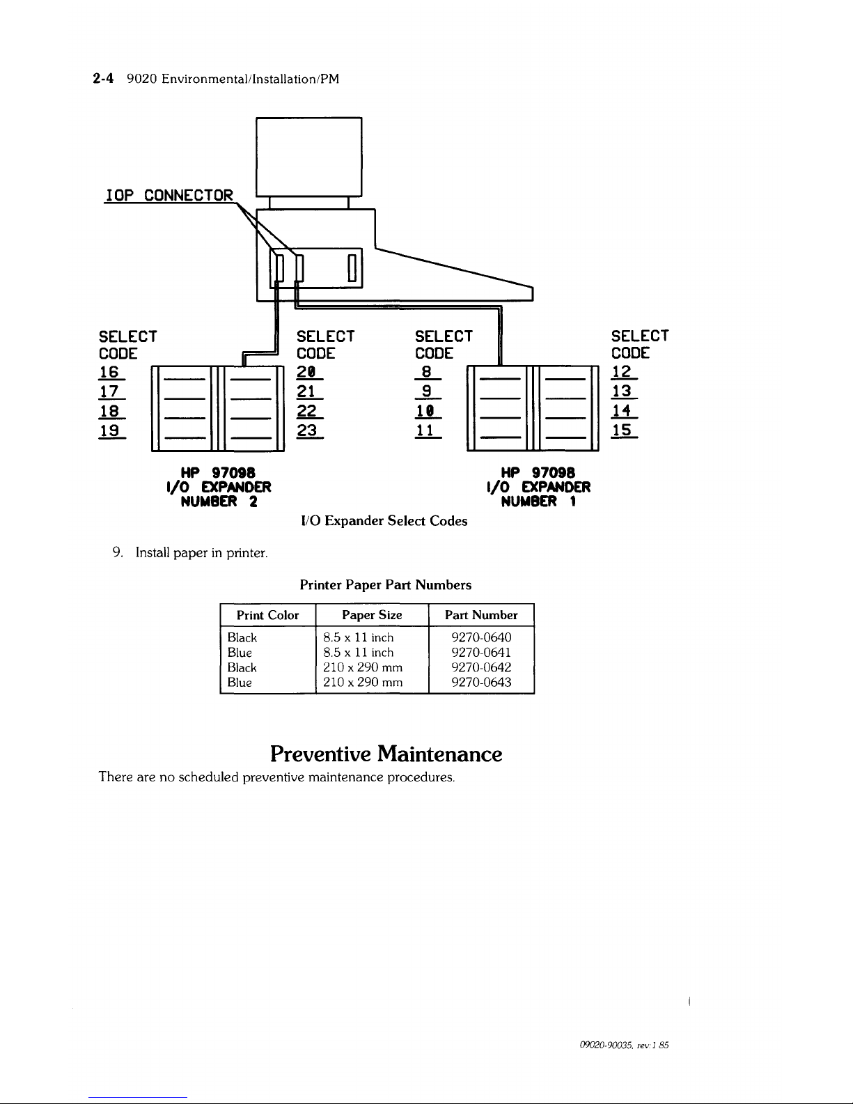
Connect
the HP 97098A
110
Expander(s)
(If
applicable).
09020-90035. rev:l:S5
2-4
9020
Environmental/Installation/PM
lOP
CONNECTOR
SELECT
CODE
~
11-
~
~
HP
97098
I/O
EXPANDER
NUMBER
2
9.
Install
paper
in
printer.
SELECT SELECT
CODE
CODE
a
~
~
.JL
~
.!.L
~
1L
110
Expander
Select
Codes
Printer
Paper
Part
Numbers
HP
97098
I/O
EXPANDER
NUMBER
1
Print Color
Paper
Size
Part
Number
Black
8.5 x
11
inch 9270-0640
Blue
8.5 x
11
inch 9270-0641
Black
210 x
290 mm
9270-0642
Blue 210 x 290
mm
9270-0643
Preventive Maintenance
There are
no
scheduled preventive maintenance procedures.
SELECT
CODE
R
rr..
li
li-
09020-90035. rev. 1
85
9020 EnvironmentalllnstallationiPM 2-5
FINSTRATE
INSTALLATION
INSTRUCTIONS
FOR
HP-QUALIFIED
PERSONNEL:
Start
on
page 2-6 (RAM/CPU), or 2-7 (lOP)
and
follow the instructions that apply to the installation
you are performing. For example,
if
you are installing a
2nd
lOP
in a 520
computer you would start
on
page 2-7,
and
perform
all
steps that begin
with:
(ALL), (ALL
2nd
lOP),
(ALL
EXCEPT 520-3rd
lOP), (520), (520 ONLY),
and
(520-2nd lOP).
ALL
RAM
and
CPU Instuctions start
on
2-6.
ALL
lOP Instructions start
on
2-7.
When completed with the installation of the finstrate, Insert the following pages in your
CE Hand-
book (after page
2-4
of either the
9020
or 9030/9040 section).
2-6
9020 Environmental/Installation/PM
RAM/CPU
FINSTRATE
INSTALLATION
1.
(ALL)
TURN THE POWER OFF
AND
DISCONNECT THE POWER CORD.
2.
(520)
Open
the
left
door.
(530) Remove the front panel.
(540) Remove the front bottom panel.
3.
(530/540 ONLY)
From the front of the computer, remove the Radio Frequency Interference
(RFI)
shield by
loosening the six thumbscrews.
4.
(ALL)
Open processor stack door.
5.
(ALL)
CAUTION
ELECTROSTATIC DISCHARGE DAMAGE CAN OCCUR IN THE
FOLLOWING
STEPS.
FOLLOW THE PRECAUTIONS IN CHAPTER
4 OF THE SERVICE MANUAL.
DO
NOT
TOUCH EDGE CONNECTOR
OR
FINSTRATE PLANE.
HOLD
FINSTRA
TE
BY EJECTORS
OR
SIDE EDGES ONLY. HAND-
LING
FINSTRATE
INCORRECTLY
COULD
CAUSE
ELECTROSTATIC DISCHARGE DAMAGE. WHEN INSTALLING
FINSTRA
TE,
HOLD
BY EJECTORS AND MOVE AIR CONTROLLER
OUT OF
THE WAY WITH THE SIDE EDGE
OF
THE FINSTRATE.
Install the finstrate in the
first
unoccupied slot from the bottom.
DO
NOT
LEAVE
EMPTY
SLOTS BETWEEN FINSTRA TES.
6.
(ALL)
Close the processor stack door. Firmly tighten thumbscrews to prevent
RFI
radiation. Re-
place the label that
is
used as a seal for the processor stack door (Part Number 5180-5201).
7.
(530/540 ONLY)
Replace
RFI
shield.
8.
(520)
Close left door.
(530)
Replace front panel.
(540)
Replace the front bottom panel.
9.
(ALL)
Connect power cord to ac outlet.
9020 EnvironmentaVInstallation/PM
2-7
1.
(ALL)
lOP
FINSTRATE
INSTALLATION
WARNING
OBSERVE
ALL
WARNINGS AND SAFETY PROCEDURES IN THE
COMPUTER SERVICE MANUAL. LETHAL VOLTAGES ARE
PRE-
SENT IN THE COMPUTER.
TURN THE POWER OFF
AND
DISCONNECT THE POWER CORD.
2.
(520 - 2nd lOP)
Remove the left door.
(520 - 3rd lOP)
Open
the left door. Remove the 1/0 expander cable from the
JlO
EXPANDER 1 slot
on
the
processor stack door
(if
connected).
(530)
Remove front panel.
(540)
Remove both front panels and flip-top cover.
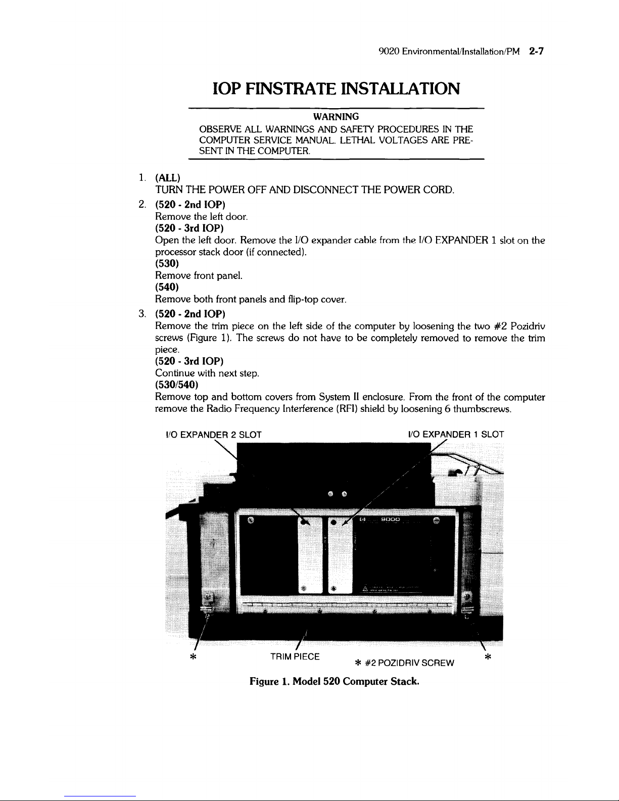
3.
(520 - 2nd lOP)
Remove the trim piece
on
the left side of the computer by loosening the two
#2
Pozidriv
screws (Figure
1).
The screws do not have to be completely removed to remove the trim
piece.
(520 - 3rd lOP)
Continue with next step.
(530/540)
Remove top
and
bottom covers from System
II
enclosure. From the front of the computer
remove the Radio Frequency Interference
(RFI)
shield by loosening 6 thumbscrews.
1/0
EXPANDER 2 SLOT
1/0
EXPANDER 1 SLOT
*
TRIM PIECE
*
#2
POZIDRIV SCREW
Figure
1.
Model 520 Computer Stack.
*
2-8
9020 Environmental/Installation/PM
4.
(520 ONLY)
Remove the flat metal plate covering the appropriate
110
EXPANDER connector slot by
removing the two
#2
Pozidriv screws (Figure 2):
(2nd
lOP)
110
EXPANDER
1.
(3rd lOP)
110
EXPANDER 2.
(530/540)
Continue with next step.
*
*
* CAPTIVE THUMBSCREW
*#2
POZIDRIV CAPTIVE SCREW
CONNECTOR
COVER
PLATE
*
Figure
2.
Series 500 Computer
Stack
Door Removal.
5.
(ALL
EXCEPT 520 - 3rd lOP)
*
Loosen the two
#2
Pozidriv captive screws
at
the bottom of the processor stack door (Figure
2).
(520 - 3rd lOP)
Continue with next step.
6.
(ALL
EXCEPT 520 - 3rd lOP)
Remove the processor stack door by loosening the two captive thumbscrews (Figure 2).
(520 - 3rd lOP)
Open
processor stack door.
9020 Environmental/lnstallationlPM
2-9
CAUTION
DO NOT TOUCH EDGE CONNECTOR
OR
FINSTRA
TE
PLANE.
HOLD
FINSTRA
TE
BY EJECTORS OR SIDE EDGES ONLY. HAND-
LING FINSTRATE INCORRECTLY
COULD CAUSE ELECTROSTATIC DISCHARGE DAMAGE. WHEN INSTALLING FINSTRATE,
HOLD
BY EJECTORS AND MOVE AIR CONTROLLER OUT OF
THE WAY WITH THE SIDE EDGE
OF
THE FINSTRATE.
7.
(ALL -2nd
lOP)
Move
all
finstrates above slot 2
up
one
slot.
(ALL • 3rd lOP)
Move
all
finstrates above slot 3
up
one
slot (Slot 3
is
first
accessible finstrate without removing
door).
8. (520
• ONLY)
Remove cable clamp from processor stack door by removing two # 1 Pozidriv screws.
9.
(ALL)
Slide the lOP finstrate into the appropriate slot without seating finstrate into the motherboard. Open the connector gate (Figure 3):
(2nd
lOP) Slot 3.
(3rd lOP) Slot 4.
CONNECTOR GATE
lOP CABLE CABLE CLAMP
IOP#2
DOOR
CONNECTOR REMOVED
Figure 3.
Series
500
Computer
lOP
Installation.
2-10 9020
EnvironmentalllnstallationiPM
10. (520)
Place lOP cable door connector over studs on ends of appropriate
I/O
EXPANDER
connec-
tor slot, and tighten connector to door
with
two nuts (Figure
3):
(2nd lOP) 1/0
EXPANDER
1 slot.
(3rd
lOP)
I/O
EXPANDER
2 slot.
(530/540)
Continue with step 12.
11. (520
ONLY)
Install cable clamp on door so that
it
holds cable(s)
in
position (Figure
4).
CONNECTOR GATE
CABLE CLAMP
Figure 4. Series
500
Computer
Stack
Door.
12. (520)
Connect the lOP cable finstrate connector to the lOP finstrate
with
cable pointing down.
Close the connector gate and seat the finstrate into the motherboard connector (Figure
4).
(530/540)
Route lOP cable through base plate. Connect lOP cable finstrate connector to finstrate.
Close connector gate and seat board into motherboard connector.
13.
(ALL
EXCEPT
520
- 3rd lOP)
Install processor stack door
with
two captive
#2
Pozidriv screws at bottom.
(520 -
3rd
lOP)
Continue with next step.
9020 EnvironmentaVInstallationlPM 2-11
14.
(ALL)
Close processor stack door. Tighten thumbscrews to prevent Radio Frequency Interference
(RFI)
radiation. Replace the label that
is
·used as a seal for the processor stack
door
(Part
Number
5180-5201).
15. (520)
CAUTION
ENSURE
THE
I/O
EXPANDER
CONNECTOR
ON
THE
PROCESSOR
STACK
DOOR
IS
COVERED,
AS
EXPLAINED
IN
THE
NEXT
STEP.
TO
PREVENT
RFI
RADIATION.
Attach I/O
expander
cable(s)
to
the appropriate
1/0
EXPANDER connector (Figure 5),
or
cover connector with plastic connector cover (Figure 6).
(530/540 - 2nd lOP)
Route lOP cable along outside of
base
plate
and
attach
lOP
cable strain relief clamp
to
base
with four
#2
Pozidriv screws. Ensure cable
is
centered in clamp
and
is
not pinched.
(530/540 -
3rd
lOP)
Remove I/O cable strain relief clamp which holds
2nd
lOP cable in place
on
outside
of
base
plate. Route lOP cable along outside of
base
plate
and
attach
lOP
cable strain relief clamp to
base
with four
#2
Pozidriv screws. Ensure cable
is
centered in clamp
and
is
not
pinched.
Figure 5. lOP Connector Attached
to
Door.
2-12 9020 EnvironmentaVInstallation/PM
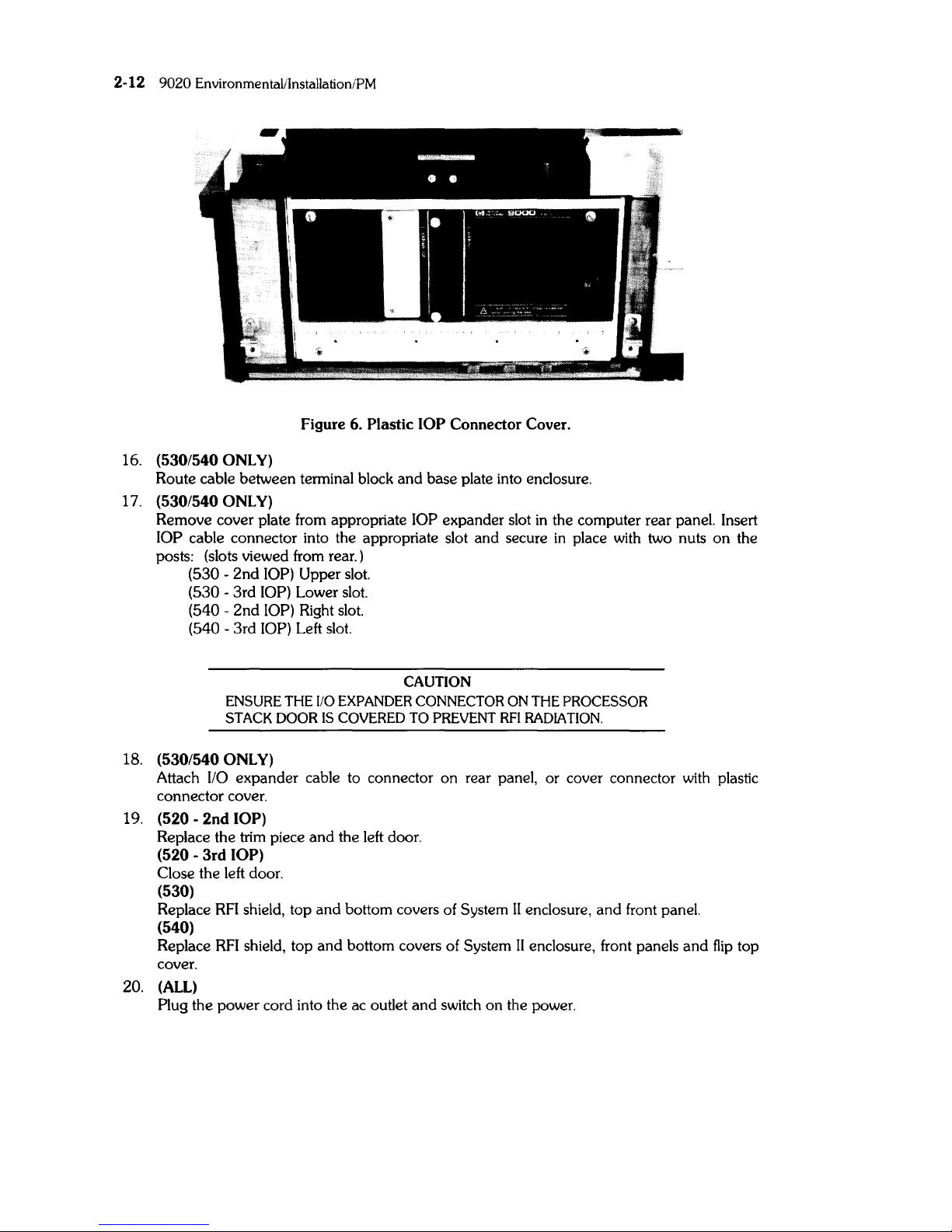
Figure 6. Plastic
lOP
Connector Cover.
16.
(530/540 ONLY)
Route cable between terminal block and base plate into enclosure.
17.
(530/540 ONLY)
Remove cover plate from appropriate lOP expander slot
in
the computer rear panel. Insert
lOP cable connector into the appropriate slot and secure
in
place
with
two nuts on the
posts: (slots viewed from rear.)
(530 -
2nd
lOP) Upper slot.
(530 - 3rd lOP) Lower slot.
(540 - 2nd lOP) Right
slot.
(540 - 3rd lOP) Left slot.
CAUTION
ENSURE
THE
110
EXPANDER CONNECTOR ON THE PROCESSOR
STACK
DOOR
IS
COVERED
TO
PREVENT
RFI
RADIATION.
18.
(530/540 ONLY)
Attach lIO expander cable to connector on rear panel, or cover connector
with
plastic
connector cover.
19. (520 -
2nd
lOP)
Replace the trim piece and the left door.
(520 -
3rd
lOP)
Close the left door.
(530)
Replace
RFl
shield, top and bottom covers of System
II
enclosure, and front panel.
(540)
Replace
RFI
shield, top and bottom covers of System
II
enclosure, front panels and
flip
top
cover.
20.
(ALL)
Plug the power cord into the ac outlet and switch on the power.

9020
EnvironmentaVlnstalJation/PM 2-13
512K RAM Board Installation Information
Instructions For HP-Qualified Personnel:
Follow the instructions that apply to the installation you are performing. For example,
if
you are
installing the
RAM
card
in a 520
computer you would perform the steps that begin with:
(ALL),
and
(520).
Load Board
Systems that are shipped from the Fort Collins Systems Division with 1 CPU, 1 lOP,
and
one
512K
Byte
RAM
Board,
will
also have a Load Board
in
the slot that
is
adjacent to the
RAM
board
(top
occupied slot).
If any other Finstrates, or
RAM,
is
added
to this configuration, the Load Board must
be
removed from the computer.
Any time the Processor Stack configuration
is
reduced to 1 CPU, 1 lOP,
and
one
512K Byte
RAM
Board, A Load Board (09855-66525)
is
required. Load Board (09855-66525)
is
a replaceable
part.
CE Handbook
When completed with the installation, insert this page and the following page
in
your CE
Handbook
(after page 2-12 of either the
9020
or 9030/9040 section).
Part
Numbers
512K Byte
RAM
(exchange)
(new)
Load Board
97047-69805
5061-6805
09855-66525
2-14 9020 Environmental/Installation/PM
512K Byte
RAM
Board
Installation
1.
(ALL)
TURN THE POWER OFF
AND
DISCONNECT THE POWER CORD.
2.
(520)
Open
the left door.
(530)
Remove the front panel.
(540)
Remove the front bottom panel.
3.
(530/540
ONLY)
From the front of the computer, remove the Radio Frequency Interference
(RFI)
shield by
loosening the six thumbscrews.
4.
(ALL)
Open
processor stack door.
5.
(ALL)
CAUTION
ELECTROSTATIC DISCHARGE DAMAGE CAN OCCUR IN THE
FOLLOWING STEPS.
FOLLOW
THE PRECAUTIONS IN CHAPTER
4 OF
THE
SERVICE MANUAL.
DO
NOT
TOUCH
EDGE CONNECTOR OR BOARD PLANE.
HOLD
BOARD BY EJECTORS OR SIDE EDGES ONLY. HANDLING THE
RAM
BOARD INCORRECTLY COULD CAUSE ELECTROSTATIC
DISCHARGE DAMAGE. WHEN INSTALLING THE RAM BOARD,
HOLD
BY
EJECTORS AND MOVE AIR CONTROLLER OUT OF
THE
WAY
WITH
THE SIDE EDGE OF THE BOARD.
Remove the Load Board (09855-66525) from the Processor Stack,
if
it
is
present and at least
one
RAM
board
is
installed. The load board
will
no
longer
be
required.
It
is
the property of the
customer.
6.
(ALL)
Install the new
RAM
board
in
the
first
unoccupied slot from the bottom.
DO
NOT
LEAVE
EMPTY SLOTS BETWEEN BOARDS.
7.
(ALL)
Close the processor stack door. Firmly tighten thumbscrews to prevent
RFI
radiation. Replace
the label that
is
used as a seal for the processor stack door (Part Number 5180-5201).
8.
(530/540
ONLY)
Replace
RFI
shield.
9.
(520)
Close left door.
(530)
Replace front panel.
(540)
Replace the front bottom panel.
10. (ALL)
Connect power cord to ac outlet.
9020
EnvironmentaVlnstallation/PM
2-15
1 Megabyte RAM Board Installation
Instructions
Read the following information then follow the instructions that apply to the installation you are
performing. For example,
if
you are installing the
RAM
Boards
in
a 520 computer you would
perform
all
steps that begin with:
(ALL),
and
(520).
RAM
Boards
1 Megabyte
RAM
Boards can only
be
installed
in
pairs. Any combination of 256K, 512K,
and
pairs
of 1 Megabyte boards can
be
used.
Load Board
If a system
is
shipped with 1 CPU, 1 lOP, and one 512K
RAM
Board,
it
will
also have a Load Board
(09855-66525)
in
the top occupied slot. When the 1 Megabyte
RAM
Boards are
added
to the
stack, the Load Board
is
no longer required
and
must be removed (assuming the 512K
RAM
board
remains
in
the system).
When the only
RAM
boards
in
the stack are 1 Megabyte
RAM
boards, a load board
is
required
if
there are six or less. The load board should
be
removed when there are more than six 1 Megabyte
RAM
boards
in
the stack, or
if
there
is
a mixture of 256K, 512K, and 1 Megabyte
RAM
boards
in
the
stack.
Any time the
Processor Stack configuration
is
changed so that
it
contains
one
of the above
configurations, a Load Board
is
required. The load Board (09855-66525)
is
a replaceable part
in
spares.
If
the load board
is
used
it
must be
in
the top
OCCUPIED
slot of the Processor Stack. Do
not leave
any
empty slots between finstates or boards.
Boot Loader ROM
When the Processor Stack contains 1 Megabyte
RAM
Boards, Boot Loader
ROM
Rev. B (09020-
80001)
must be used,
and
UNIX
4.0 or Basic 2.0 software must be used.
Boot Loader
ROM 09020-80000 can be used with
UNIX
4.0 or Basic 2.0 (or any previous software
versions) as long as the stack
DOES
NOT
contain a 1 Megabyte
RAM
Board.
Boot Loader
ROM
Rev. B (09020-80001) can be used
with
any
RAM
configuration but
MUST
use
UNIX
4.0 or BASIC 2.0 software (any earlier versions of software cannot
be
used with this boot
loader).
Access Times
When the 1 Megabyte
RAM
Boards are installed
in
a computer, the access times
will
be
slower.
The
customer may notice this slower process time during operation.
System
Functional Test
The previous SFT tests (Part Number 09020-10010 Rev. 2.0) are not compatible with the BASIC
2.0 Operating System. The updated version of the
SIT
must be used with this operating system.
The
4.0 HP-UX Operating System contains the same System Functional Tests (SFT) as the pre-
vious HP-UX. They are located
in
the CE utilities dictionary.
09020-90035, rev.L85
2-16
9020 EnvironmentallinstallationlPM
Part
Numbers
1 Megabyte RAM Board (exchange)
(new)
Boot Loader
ROM *
Load Board
97046-69704
5061-7704
09020-80000
(Rev.
A)
09020-80001
(Rev.
B)
09855-66525
*
See
BOOT LOADER
ROM
on
the previous page for part number applicability. When ordering
the
ROM,
the serial number and model number of the computer
must
be given to the individual
taking the order.
CE Handbook
When completed with the installation, insert these pages
in
your CE Handbook (after page 2-14 of
either the
9020
or
9030/9040 section).
RAM Board Installation
1.
(ALL)
TURN THE POWER OFF
AND
DISCONNECT THE POWER CORD.
2.
(520)
Open
the left door.
(530)
Remove the front panel.
(540)
Remove both front panels and the fliptop cover.
3.
(530/540 ONLY)
From the front of the computer, remove the Radio Frequency Interference
(RFI)
shield by
loosening the six thumbscrews.
4.
(ALL)
Open
processor stack door.
5.
(ALL)
CAUTION
ELECTROSTATIC DISCHARGE DAMAGE CAN OCCUR IN THE
FOLLOWING
STEPS.
FOLLOW THE PRECAUTIONS IN CHAPTER
4
OF THE SERVICE MANUAL.
DO NOT TOUCH EDGE CONNECTOR
OR
BOARD PLANE.
HOLD
BOARD
BY
EJECTORS OR SIDE EDGES ONLY. HANDLING THE
RAM
BOARD INCORRECTLY COULD CAUSE ELECTROSTATIC
DISCHARGE DAMAGE. WHEN INSTALLING THE RAM BOARD,
HOLD
BY EJECTORS AND MOVE AIR CONTROLLER OUT OF
THE WAY WITH THE SIDE EDGE
OF
THE BOARD.
Remove the Load Board (09855-66525) from the Processor Stack,
if
it
is
present.
6.
(ALL)
Install the
RAM
boards starting with the
first
unoccupied slot from the bottom. DO NOT
LEAVE
EMPTY SLOTS BETWEEN BOARDS. If a Load Board
is
required, install
it
in
the
next slot above the
RAM.
(see "Load Board"
in
the information at the front of the proce-
dure.)
7.
(ALL)
Close the processor stack door. Firmly tighten thumbscrews to prevent
RFI
radiation. Re-
place the label that
is
used as a seal for the processor stack door (Part Number 5180-5201).
09020-90035. rev:
1185
9020 Environmental/Installation/PM
2-17
8.
(520)
Close the left side door.
(530/540)
Replace the
RFI
shield.
9.
(520)
Remove right side door.
(530/540)
Remove the top cover of the System
II
enclosure. The cover has
one
captive screw
at
the
back of the box. Loosen the screw and slide the cover back and away from the box.
10.
(530/540 ONLY)
Disconnect the ac module cable and the service module cable.
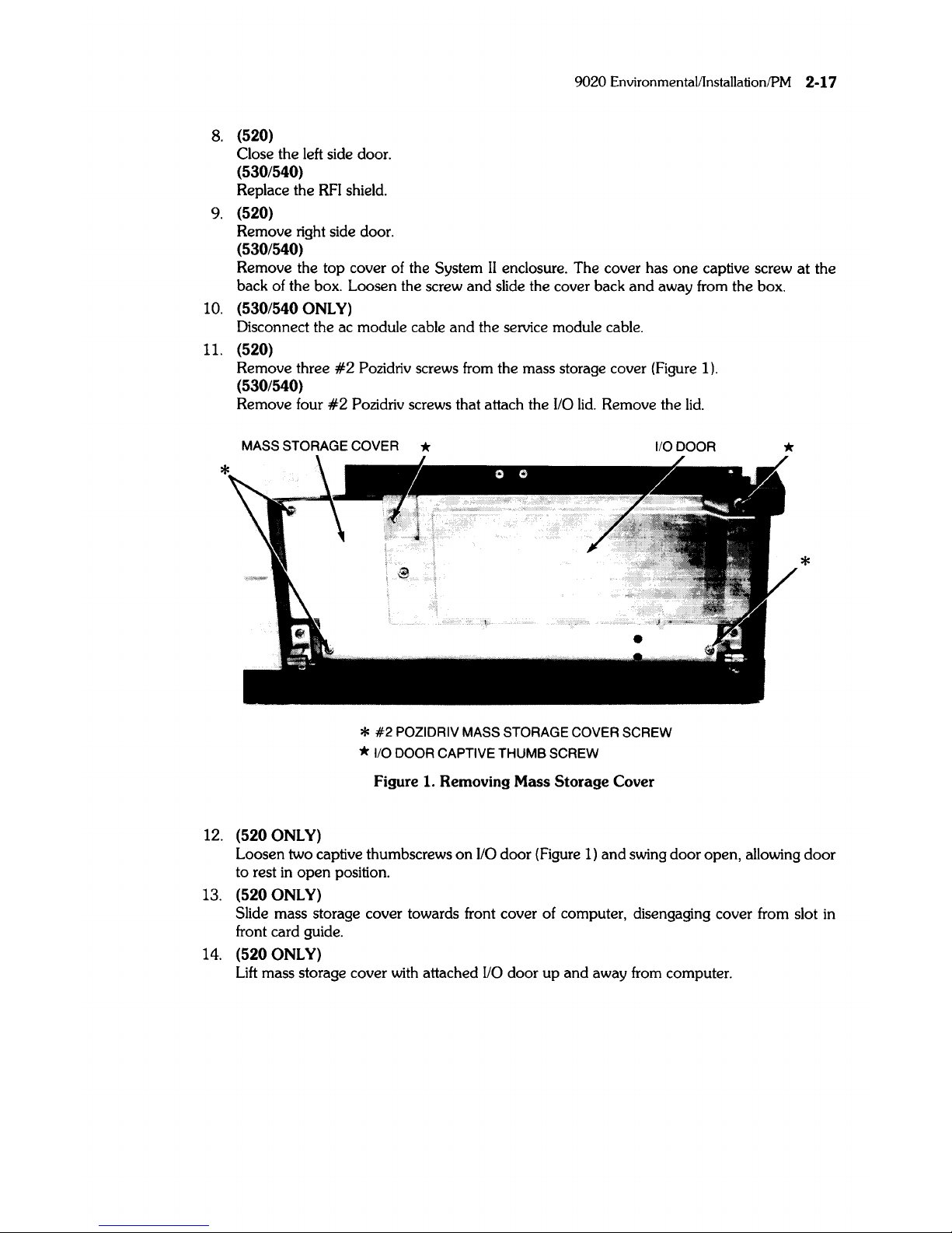
11.
(520)
Remove three
#2
Pozidriv screws from the mass storage cover (Figure
1).
(530/540)
Remove four
#2
Pozidriv screws that attach the
110
lid.
Remove the
lid.
MASS STORAGE COVER *
1/0 DOOR
12.
(520 ONLY)
*
#2
POZIDRIV MASS STORAGE COVER SCREW
* 1/0 DOOR CAPTIVE
THUMB
SCREW
Figure 1. Removing Mass
Storage
Cover
*
*
Loosen two captive thumbscrews on
1/0
door (Figure
1)
and swing door open, allowing
door
to rest
in
open position.
13.
(520 ONLY)
Slide mass storage cover towards front cover of computer, disengaging cover from slot in
front card
gUide.
14.
(520 ONLY)
Lift
mass storage cover with attached
1/0
door up and away from computer.
2-18
9020 EnvironmentaVlnstallation/PM
15. (520 With
Bootstrap
Loader Card)
Remove Bootstrap Loader card and replace the Bootstrap Loader
ROM
with the new
ROM.
Use tool 8710-0585. Reinstall the card
in
the
I/O
card cage.
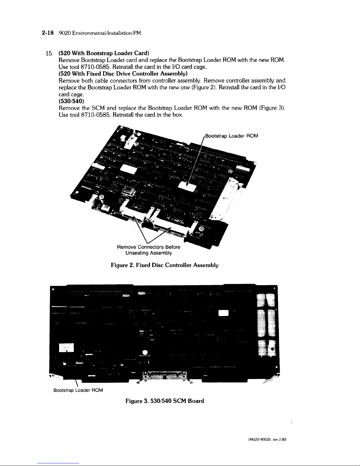
(520 With Fixed Disc Drive Controller Assembly)
Remove both cable connectors from controller assembly. Remove controller assembly and
replace the Bootstrap Loader
ROM
with the new one (Figure 2). Reinstall the card in the
I/O
card cage.
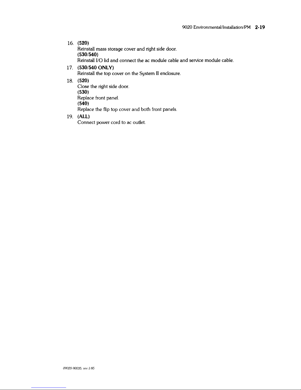
(530/540)
Remove the SCM
and
replace the Bootstrap Loader
ROM
with
the new
ROM
(Figure 3).
Use tool 8710-0585. Reinstall the card
in
the box.
Figure 2. Fixed Disc Controller Assembly
Bootstrap Loader ROM
Figure 3. 530/540 SCM
Board
09020·90035. rev:
1185
16. (520)
Reinstall mass storage cover
and
right side door.
(530/540)
9020
Environmental/Installation/PM 2-19
Reinstall I/O
lid
and
connect the ac module cable
and
service module cable.
17.
(530/540 ONLY)
Reinstall the top cover
on
the System
II
enclosure.
18. (520)
Close the right side door.
(530)
Replace front panel.
(540)
Replace the
flip
top cover
and
both front panels.
19.
(ALL)
Connect power cord to ac outlet.
09020-90035, rev. 1/85

2-20
9020
EnvironmentaVlnstallation/PM
 Loading...