

HP 9000 V2500 SCA, 9000 V2600 SCA Operator's Manual

Operator’s Guide
HP 9000 V2500/V2600 SCA Server
First Edition
A5845-96001
Customer Order Number: A5845-90001
July 1999
Printed in: USA

Revision History
Edition: First
Document Number: A5845-96001
Notice
Copyright Hewlett-Packard Company 1999. All Rights Reserved.
Reproduction, adaptation, or translation with out prior wr itten
permission is prohibited, except as allowed under the copyright laws.
The infor mat i on co n ta i ned i n th is do cument is s u bj ec t to c h ang e wit h out
notice.
Hewlett-Packard make s no warranty of any kind with regard to this
material, including, but not limited to, the implied warranties of
merchantability and fitness for a particular purpose. Hewlett-Packard
shall not be liable for errors contained herein or for incidental or
consequential damages in connection with the furnishing, performance
or use of this mater ial.

Contents
Preface . . . . . . . . . . . . . . . . . . . . . . . . . . . . . . . . . . . . . . . . . . . . . . . . . . . . . . . . . . . . . . . . . xiii
Notational conventions . . . . . . . . . . . . . . . . . . . . . . . . . . . . . . . . . . . . . . xiv
Safety and regulatory information . . . . . . . . . . . . . . . . . . . . . . . . . . . . . xvi
Safety in material handling . . . . . . . . . . . . . . . . . . . . . . . . . . . . . . . . . xvi
USA radio frequency interference FCC Notice. . . . . . . . . . . . . . . . . . xvi
Japanese radio frequency interference VCCI . . . . . . . . . . . . . . . . . . xvii
EMI statement (European Union only). . . . . . . . . . . . . . . . . . . . . . . xvii
Digital apparatus statement (Canada) . . . . . . . . . . . . . . . . . . . . . . . xvii
BCIQ (Taiwan) . . . . . . . . . . . . . . . . . . . . . . . . . . . . . . . . . . . . . . . . . . xvii
Acoustics (Germany). . . . . . . . . . . . . . . . . . . . . . . . . . . . . . . . . . . . . . xviii
IT power system . . . . . . . . . . . . . . . . . . . . . . . . . . . . . . . . . . . . . . . . . xviii
High leakage current . . . . . . . . . . . . . . . . . . . . . . . . . . . . . . . . . . . . . xviii
Installation conditions (U.S.) . . . . . . . . . . . . . . . . . . . . . . . . . . . . . . . . xix
Fuse cautions . . . . . . . . . . . . . . . . . . . . . . . . . . . . . . . . . . . . . . . . . . . . xix
Associated documents . . . . . . . . . . . . . . . . . . . . . . . . . . . . . . . . . . . . . . . .xx
Technical assistance . . . . . . . . . . . . . . . . . . . . . . . . . . . . . . . . . . . . . . . . xxi
Reader feedback. . . . . . . . . . . . . . . . . . . . . . . . . . . . . . . . . . . . . . . . . . . xxii
1 Overview . . . . . . . . . . . . . . . . . . . . . . . . . . . . . . . . . . . . . . . . . . . . . . . . . . . . . . . . . . . . . . . 1
V-Class System Components. . . . . . . . . . . . . . . . . . . . . . . . . . . . . . . . . . . .2
The Service Support Processor . . . . . . . . . . . . . . . . . . . . . . . . . . . . . . . .3
Server Console and Diagnostic Connections . . . . . . . . . . . . . . . . . . . .4
V-Class Server Architecture . . . . . . . . . . . . . . . . . . . . . . . . . . . . . . . . . . . .6
V2500/V2600 Crossbar Interconnection . . . . . . . . . . . . . . . . . . . . . . . . .6
V2500/V2600 Cabinet Components. . . . . . . . . . . . . . . . . . . . . . . . . . . . .8
Core Utilities Board . . . . . . . . . . . . . . . . . . . . . . . . . . . . . . . . . . . . . . .9
Processors . . . . . . . . . . . . . . . . . . . . . . . . . . . . . . . . . . . . . . . . . . . . . . .9
Memory . . . . . . . . . . . . . . . . . . . . . . . . . . . . . . . . . . . . . . . . . . . . . . . . .9
Input/Output . . . . . . . . . . . . . . . . . . . . . . . . . . . . . . . . . . . . . . . . . . . .12
Multiple-Cabinet Server Connections. . . . . . . . . . . . . . . . . . . . . . . . . .15
V2500/V2600 Cabinet Configurations . . . . . . . . . . . . . . . . . . . . . . . . . . .18
2 Indicators, switches, and displays . . . . . . . . . . . . . . . . . . . . . . . . . . . . . . . . . . . . . . . . 21
Operator panel. . . . . . . . . . . . . . . . . . . . . . . . . . . . . . . . . . . . . . . . . . . . . .22
Key switch panel. . . . . . . . . . . . . . . . . . . . . . . . . . . . . . . . . . . . . . . . . . .23
Key switch . . . . . . . . . . . . . . . . . . . . . . . . . . . . . . . . . . . . . . . . . . . . . .23
DC ON LED. . . . . . . . . . . . . . . . . . . . . . . . . . . . . . . . . . . . . . . . . . . . .23
TOC . . . . . . . . . . . . . . . . . . . . . . . . . . . . . . . . . . . . . . . . . . . . . . . . . . .24
Table of Contents iii

DVD-ROM drive . . . . . . . . . . . . . . . . . . . . . . . . . . . . . . . . . . . . . . . . . . 24
Disk loading slot . . . . . . . . . . . . . . . . . . . . . . . . . . . . . . . . . . . . . . . . 24
Busy indicator . . . . . . . . . . . . . . . . . . . . . . . . . . . . . . . . . . . . . . . . . . 25
Eject button . . . . . . . . . . . . . . . . . . . . . . . . . . . . . . . . . . . . . . . . . . . . 25
Optional DAT drive. . . . . . . . . . . . . . . . . . . . . . . . . . . . . . . . . . . . . . . . 25
LEDs. . . . . . . . . . . . . . . . . . . . . . . . . . . . . . . . . . . . . . . . . . . . . . . . . . 25
Eject button . . . . . . . . . . . . . . . . . . . . . . . . . . . . . . . . . . . . . . . . . . . . 26
System Displays . . . . . . . . . . . . . . . . . . . . . . . . . . . . . . . . . . . . . . . . . . . . 27
LCD (Liquid Crystal Display) . . . . . . . . . . . . . . . . . . . . . . . . . . . . . . . 28
Node status line . . . . . . . . . . . . . . . . . . . . . . . . . . . . . . . . . . . . . . . . . 28
Processor status line . . . . . . . . . . . . . . . . . . . . . . . . . . . . . . . . . . . . . 28
Message display line . . . . . . . . . . . . . . . . . . . . . . . . . . . . . . . . . . . . . 30
Attention light bar . . . . . . . . . . . . . . . . . . . . . . . . . . . . . . . . . . . . . . . . 31
Environmental errors . . . . . . . . . . . . . . . . . . . . . . . . . . . . . . . . . . . . 32
3 SSP operation . . . . . . . . . . . . . . . . . . . . . . . . . . . . . . . . . . . . . . . . . . . . . . . . . . . . . . . . . . 35
SSP and the V-Class system . . . . . . . . . . . . . . . . . . . . . . . . . . . . . . . . . . 36
SSP log-on. . . . . . . . . . . . . . . . . . . . . . . . . . . . . . . . . . . . . . . . . . . . . . . . . 37
SSP sppuser windows . . . . . . . . . . . . . . . . . . . . . . . . . . . . . . . . . . . . . . 37
Message window . . . . . . . . . . . . . . . . . . . . . . . . . . . . . . . . . . . . . . . . 40
Console window (sppconsole - complex console). . . . . . . . . . . . . . . . 40
Console window (sppconsole - Node X console) . . . . . . . . . . . . . . . . 40
Console bar. . . . . . . . . . . . . . . . . . . . . . . . . . . . . . . . . . . . . . . . . . . . . 40
ksh shell windows . . . . . . . . . . . . . . . . . . . . . . . . . . . . . . . . . . . . . . . 40
Using the CDE (Common Desktop Environment) Workspace menu . . 41
CDE Workspace menu . . . . . . . . . . . . . . . . . . . . . . . . . . . . . . . . . . . . . 41
Using the console . . . . . . . . . . . . . . . . . . . . . . . . . . . . . . . . . . . . . . . . . . . 45
Creating new console windows. . . . . . . . . . . . . . . . . . . . . . . . . . . . . . . 45
Starting the console . . . . . . . . . . . . . . . . . . . . . . . . . . . . . . . . . . . . . . . 45
Starting the console from the Workspace menu . . . . . . . . . . . . . . . 46
Starting the console using the sppconsole command. . . . . . . . . . . . 46
Starting the console using ts_config . . . . . . . . . . . . . . . . . . . . . . . . . 47
Starting the console using the consolebar . . . . . . . . . . . . . . . . . . . . 48
Starting the console by logging back on . . . . . . . . . . . . . . . . . . . . . . 49
Console commands . . . . . . . . . . . . . . . . . . . . . . . . . . . . . . . . . . . . . . . . 49
Watching the console . . . . . . . . . . . . . . . . . . . . . . . . . . . . . . . . . . . . . 50
Assuming control of the console . . . . . . . . . . . . . . . . . . . . . . . . . . . . 51
Changing a console connection . . . . . . . . . . . . . . . . . . . . . . . . . . . . . 52
Accessing system logs . . . . . . . . . . . . . . . . . . . . . . . . . . . . . . . . . . . . . . 52
The set_complex command. . . . . . . . . . . . . . . . . . . . . . . . . . . . . . . . . . 52
Targeting commands to nodes . . . . . . . . . . . . . . . . . . . . . . . . . . . . . . . 53
SSP file system. . . . . . . . . . . . . . . . . . . . . . . . . . . . . . . . . . . . . . . . . . . . . 54
/spp/etc. . . . . . . . . . . . . . . . . . . . . . . . . . . . . . . . . . . . . . . . . . . . . . . . . . 54
iv Table of Contents

/spp/bin . . . . . . . . . . . . . . . . . . . . . . . . . . . . . . . . . . . . . . . . . . . . . . . . . .55
/spp/scripts . . . . . . . . . . . . . . . . . . . . . . . . . . . . . . . . . . . . . . . . . . . . . . .55
/spp/data/complex_name. . . . . . . . . . . . . . . . . . . . . . . . . . . . . . . . . . . . .55
/spp/firmware . . . . . . . . . . . . . . . . . . . . . . . . . . . . . . . . . . . . . . . . . . . . .56
/spp/est . . . . . . . . . . . . . . . . . . . . . . . . . . . . . . . . . . . . . . . . . . . . . . . . . .56
/spp/man . . . . . . . . . . . . . . . . . . . . . . . . . . . . . . . . . . . . . . . . . . . . . . . . .56
Device files . . . . . . . . . . . . . . . . . . . . . . . . . . . . . . . . . . . . . . . . . . . . . . .57
System log pathnames. . . . . . . . . . . . . . . . . . . . . . . . . . . . . . . . . . . . . . . .58
4 Firmware (OBP and PDC) . . . . . . . . . . . . . . . . . . . . . . . . . . . . . . . . . . . . . . . . . . . . . . . 59
Boot sequence. . . . . . . . . . . . . . . . . . . . . . . . . . . . . . . . . . . . . . . . . . . . . . .60
Boot process output . . . . . . . . . . . . . . . . . . . . . . . . . . . . . . . . . . . . . . . . . .62
HP mode boot menu. . . . . . . . . . . . . . . . . . . . . . . . . . . . . . . . . . . . . . . . . .64
Enabling Autoboot. . . . . . . . . . . . . . . . . . . . . . . . . . . . . . . . . . . . . . . . . . .67
Syntax . . . . . . . . . . . . . . . . . . . . . . . . . . . . . . . . . . . . . . . . . . . . . . . . . . .67
Examples. . . . . . . . . . . . . . . . . . . . . . . . . . . . . . . . . . . . . . . . . . . . . . . . .68
HElp command . . . . . . . . . . . . . . . . . . . . . . . . . . . . . . . . . . . . . . . . . . . . . .69
Syntax . . . . . . . . . . . . . . . . . . . . . . . . . . . . . . . . . . . . . . . . . . . . . . . . . . .69
Examples. . . . . . . . . . . . . . . . . . . . . . . . . . . . . . . . . . . . . . . . . . . . . . . . .69
5 Configuration utilities . . . . . . . . . . . . . . . . . . . . . . . . . . . . . . . . . . . . . . . . . . . . . . . . . . 71
ts_config . . . . . . . . . . . . . . . . . . . . . . . . . . . . . . . . . . . . . . . . . . . . . . . . . . .72
Starting ts_config . . . . . . . . . . . . . . . . . . . . . . . . . . . . . . . . . . . . . . . . . .72
ts_config operation . . . . . . . . . . . . . . . . . . . . . . . . . . . . . . . . . . . . . . . . .73
Configuration procedures. . . . . . . . . . . . . . . . . . . . . . . . . . . . . . . . . . . .75
Upgrade JTAG firmware . . . . . . . . . . . . . . . . . . . . . . . . . . . . . . . . . .75
Configure a Node. . . . . . . . . . . . . . . . . . . . . . . . . . . . . . . . . . . . . . . . .77
Configure the scub_ip address . . . . . . . . . . . . . . . . . . . . . . . . . . . . . .81
Reset the Node . . . . . . . . . . . . . . . . . . . . . . . . . . . . . . . . . . . . . . . . . .82
Deconfigure a Node. . . . . . . . . . . . . . . . . . . . . . . . . . . . . . . . . . . . . . .84
Add/Configure the Terminal Mux . . . . . . . . . . . . . . . . . . . . . . . . . . .84
Remove terminal mux. . . . . . . . . . . . . . . . . . . . . . . . . . . . . . . . . . . . .85
Console sessions . . . . . . . . . . . . . . . . . . . . . . . . . . . . . . . . . . . . . . . . .85
V2500/V2600 SCA (multinode) configuration. . . . . . . . . . . . . . . . . . . .87
V2500/V2600 split SCA configuration. . . . . . . . . . . . . . . . . . . . . . . . . .92
ts_config files . . . . . . . . . . . . . . . . . . . . . . . . . . . . . . . . . . . . . . . . . . . . .95
SSP-to-system communications . . . . . . . . . . . . . . . . . . . . . . . . . . . . . . . .97
LAN communications. . . . . . . . . . . . . . . . . . . . . . . . . . . . . . . . . . . . . . .98
SSP host name and IP addresses . . . . . . . . . . . . . . . . . . . . . . . . . . . . .98
Serial communications. . . . . . . . . . . . . . . . . . . . . . . . . . . . . . . . . . . . . .99
ccmd . . . . . . . . . . . . . . . . . . . . . . . . . . . . . . . . . . . . . . . . . . . . . . . . . . . . .100
xconfig . . . . . . . . . . . . . . . . . . . . . . . . . . . . . . . . . . . . . . . . . . . . . . . . . . .102
Menu bar. . . . . . . . . . . . . . . . . . . . . . . . . . . . . . . . . . . . . . . . . . . . . . . .105
Table of Contents v

Node configuration map . . . . . . . . . . . . . . . . . . . . . . . . . . . . . . . . . . . 106
Node control panel . . . . . . . . . . . . . . . . . . . . . . . . . . . . . . . . . . . . . . . 107
Configuration utilities . . . . . . . . . . . . . . . . . . . . . . . . . . . . . . . . . . . . . . 110
autoreset . . . . . . . . . . . . . . . . . . . . . . . . . . . . . . . . . . . . . . . . . . . . . . . 110
est_config. . . . . . . . . . . . . . . . . . . . . . . . . . . . . . . . . . . . . . . . . . . . . . . 110
report_cfg. . . . . . . . . . . . . . . . . . . . . . . . . . . . . . . . . . . . . . . . . . . . . . . 111
Effects of hardware and software deconfiguration . . . . . . . . . . . . 112
report_cfg summary report . . . . . . . . . . . . . . . . . . . . . . . . . . . . . . . 112
report_cfg ASIC report . . . . . . . . . . . . . . . . . . . . . . . . . . . . . . . . . . 113
report_cfg I/O report . . . . . . . . . . . . . . . . . . . . . . . . . . . . . . . . . . . . 113
report_cfg memory report . . . . . . . . . . . . . . . . . . . . . . . . . . . . . . . . 114
report_cfg processor report . . . . . . . . . . . . . . . . . . . . . . . . . . . . . . . 115
xsecure. . . . . . . . . . . . . . . . . . . . . . . . . . . . . . . . . . . . . . . . . . . . . . . . . 115
6 HP-UX Operating System . . . . . . . . . . . . . . . . . . . . . . . . . . . . . . . . . . . . . . . . . . . . . . . 117
HP-UX on the V2500/V2600 . . . . . . . . . . . . . . . . . . . . . . . . . . . . . . . . . 118
Displaying System Information . . . . . . . . . . . . . . . . . . . . . . . . . . . . . 118
Listing the Server Hardware Configuration . . . . . . . . . . . . . . . . . 118
Configuring HP-UX for V-Class Servers . . . . . . . . . . . . . . . . . . . . . . 120
HP-UX parameter sets . . . . . . . . . . . . . . . . . . . . . . . . . . . . . . . . . . 120
Multiple-cabinet kernel configurations . . . . . . . . . . . . . . . . . . . . . 121
Process and Thread “Gang Scheduling”. . . . . . . . . . . . . . . . . . . . . . . 122
HP-UX 11.10 SCA Enhancements . . . . . . . . . . . . . . . . . . . . . . . . . . . 122
HP-UX SCA Features . . . . . . . . . . . . . . . . . . . . . . . . . . . . . . . . . . . 123
Starting HP-UX . . . . . . . . . . . . . . . . . . . . . . . . . . . . . . . . . . . . . . . . . . . 125
Power-On Sequence. . . . . . . . . . . . . . . . . . . . . . . . . . . . . . . . . . . . . . . 126
Boot variables . . . . . . . . . . . . . . . . . . . . . . . . . . . . . . . . . . . . . . . . . . . 127
Reviewing the state of the file system . . . . . . . . . . . . . . . . . . . . . . . . 128
Stopping HP-UX. . . . . . . . . . . . . . . . . . . . . . . . . . . . . . . . . . . . . . . . . . . 130
Shutdown considerations . . . . . . . . . . . . . . . . . . . . . . . . . . . . . . . . . . 130
Rebooting the system . . . . . . . . . . . . . . . . . . . . . . . . . . . . . . . . . . . . . 132
Shutting down the system . . . . . . . . . . . . . . . . . . . . . . . . . . . . . . . . . 133
Resetting the V2500/V2600 server hardware . . . . . . . . . . . . . . . . . . 134
7 Recovering from failures . . . . . . . . . . . . . . . . . . . . . . . . . . . . . . . . . . . . . . . . . . . . . . . 137
Collecting information . . . . . . . . . . . . . . . . . . . . . . . . . . . . . . . . . . . . . 138
Performance problems . . . . . . . . . . . . . . . . . . . . . . . . . . . . . . . . . . . . . . 139
System hangs . . . . . . . . . . . . . . . . . . . . . . . . . . . . . . . . . . . . . . . . . . . . . 140
System panics. . . . . . . . . . . . . . . . . . . . . . . . . . . . . . . . . . . . . . . . . . . . . 141
Peripheral problem . . . . . . . . . . . . . . . . . . . . . . . . . . . . . . . . . . . . . . . 142
Interface card and system problem . . . . . . . . . . . . . . . . . . . . . . . . . . 143
File system problem . . . . . . . . . . . . . . . . . . . . . . . . . . . . . . . . . . . . . . 144
LAN communication problem. . . . . . . . . . . . . . . . . . . . . . . . . . . . . . . 144
vi Table of Contents

Logical Volume Manager (LVM) related problem. . . . . . . . . . . . . . . .145
Recovery from other situations . . . . . . . . . . . . . . . . . . . . . . . . . . . . . .145
Rebooting the system . . . . . . . . . . . . . . . . . . . . . . . . . . . . . . . . . . . . . . .146
Monitoring the system after a system panic. . . . . . . . . . . . . . . . . . . .146
Abnormal system shutdowns . . . . . . . . . . . . . . . . . . . . . . . . . . . . . . . . .147
Fast dump. . . . . . . . . . . . . . . . . . . . . . . . . . . . . . . . . . . . . . . . . . . . . . .147
Overview of the dump and save cycle . . . . . . . . . . . . . . . . . . . . . . . . .148
Crash dump destination and contents . . . . . . . . . . . . . . . . . . . . . . . .148
New SCA-Extended Crash Dump Format. . . . . . . . . . . . . . . . . . . .149
Memory Dumped on V2500/V2600 SCA Servers. . . . . . . . . . . . . . .149
Configuration criteria . . . . . . . . . . . . . . . . . . . . . . . . . . . . . . . . . . . .150
System recovery time . . . . . . . . . . . . . . . . . . . . . . . . . . . . . . . . . . . .150
Crash information integrity . . . . . . . . . . . . . . . . . . . . . . . . . . . . . . .152
Disk space needs . . . . . . . . . . . . . . . . . . . . . . . . . . . . . . . . . . . . . . . .154
Defining dump devices. . . . . . . . . . . . . . . . . . . . . . . . . . . . . . . . . . . . .155
Kernel dump device definitions . . . . . . . . . . . . . . . . . . . . . . . . . . . .156
Runtime dump device definitions. . . . . . . . . . . . . . . . . . . . . . . . . . .158
Dump order . . . . . . . . . . . . . . . . . . . . . . . . . . . . . . . . . . . . . . . . . . . .160
What happens when the system crashes?. . . . . . . . . . . . . . . . . . . . . .160
Operator override options. . . . . . . . . . . . . . . . . . . . . . . . . . . . . . . . .161
The dump. . . . . . . . . . . . . . . . . . . . . . . . . . . . . . . . . . . . . . . . . . . . . .161
The reboot . . . . . . . . . . . . . . . . . . . . . . . . . . . . . . . . . . . . . . . . . . . . .162
What to do after the system has rebooted?. . . . . . . . . . . . . . . . . . . . .162
Using crashutil to complete the saving of a dump . . . . . . . . . . . . .163
Crash dump format conversion . . . . . . . . . . . . . . . . . . . . . . . . . . . .163
Analyzing crash dumps. . . . . . . . . . . . . . . . . . . . . . . . . . . . . . . . . . .164
Appendix A: LED codes. . . . . . . . . . . . . . . . . . . . . . . . . . . . . . . . . . . . . . . . . . . . . . . . . . . 165
Power on detected errors. . . . . . . . . . . . . . . . . . . . . . . . . . . . . . . . . . . . .166
CUB detected memory power fail . . . . . . . . . . . . . . . . . . . . . . . . . . . . . .171
CUB detected processor error . . . . . . . . . . . . . . . . . . . . . . . . . . . . . . . . .172
CUB detected I/O error . . . . . . . . . . . . . . . . . . . . . . . . . . . . . . . . . . . . . .173
CUB detected fan error . . . . . . . . . . . . . . . . . . . . . . . . . . . . . . . . . . . . . .174
CUB detected ambient air errors . . . . . . . . . . . . . . . . . . . . . . . . . . . . . .175
CUB detected hard error. . . . . . . . . . . . . . . . . . . . . . . . . . . . . . . . . . . . .176
CUB detected intake ambient air error . . . . . . . . . . . . . . . . . . . . . . . . .177
CUB detected dc error . . . . . . . . . . . . . . . . . . . . . . . . . . . . . . . . . . . . . . .178
Table of Contents vii

viii Table of Contents

Figures
Figure 1 Japanese radio frequency notice. . . . . . . . . . . . . . . . . . . . . . . . . . . . . . . . . . . xvii
Figure 2 BCIQ (Taiwan). . . . . . . . . . . . . . . . . . . . . . . . . . . . . . . . . . . . . . . . . . . . . . . . . xviii
Figure 3 V-Class Server Components: Cabinet and Service Support Processor. . . . . . . .2
Figure 4 Four-Cabinet V2500/V2600 Server Components. . . . . . . . . . . . . . . . . . . . . . . . .3
Figure 5 Console and Diagnostic Connections for a Four-Cabinet V2500/V2600 Server.5
Figure 6 Functional Diagram of a Single-Cabinet V2500/V2600 Server . . . . . . . . . . . . .7
Figure 7 V2500/V2600 HyperPlane Crossbar Connections . . . . . . . . . . . . . . . . . . . . . . . .8
Figure 8 Conceptual Overview of V2500/V2600 Memory Board . . . . . . . . . . . . . . . . . . .10
Figure 9 Numbering and Locations of Single-Cabinet V2500/V2600 PCI I/O . . . . . . . .13
Figure 10 Numbering and Locations of Multiple-Cabinet V2500/V2600 PCI I/O . . . . . .14
Figure 11 Four-Cabinet V2500/V2600 Server CTI Cable Connections. . . . . . . . . . . . . . .16
Figure 12 Sample V2500/V2600 Cabinet Configurations . . . . . . . . . . . . . . . . . . . . . . . . .19
Figure 13 Operator panel. . . . . . . . . . . . . . . . . . . . . . . . . . . . . . . . . . . . . . . . . . . . . . . . . . .22
Figure 14 Key switch panel . . . . . . . . . . . . . . . . . . . . . . . . . . . . . . . . . . . . . . . . . . . . . . . . .23
Figure 15 DVD-ROM drive . . . . . . . . . . . . . . . . . . . . . . . . . . . . . . . . . . . . . . . . . . . . . . . . .24
Figure 16 DDS-3 DAT drive front panel . . . . . . . . . . . . . . . . . . . . . . . . . . . . . . . . . . . . . . .25
Figure 17 System displays . . . . . . . . . . . . . . . . . . . . . . . . . . . . . . . . . . . . . . . . . . . . . . . . . .27
Figure 18 Front panel LCD . . . . . . . . . . . . . . . . . . . . . . . . . . . . . . . . . . . . . . . . . . . . . . . . .28
Figure 19 SSP user windows for V2500/V2600 servers with one node . . . . . . . . . . . . . . .38
Figure 20 SSP user windows for V2500/V2600 servers with more than two nodes . . . . .39
Figure 21 SSP Workspace submenus for V2500/V2600 . . . . . . . . . . . . . . . . . . . . . . . . . . .42
Figure 22 SSP Workspace submenus for V2500/V2600 . . . . . . . . . . . . . . . . . . . . . . . . . . .42
Figure 23 SSP file system for V2500/V2600 servers . . . . . . . . . . . . . . . . . . . . . . . . . . . . .54
Figure 24 Boot process . . . . . . . . . . . . . . . . . . . . . . . . . . . . . . . . . . . . . . . . . . . . . . . . . . . . .61
Figure 25 ts_config sample display. . . . . . . . . . . . . . . . . . . . . . . . . . . . . . . . . . . . . . . . .73
Figure 26 ts_config showing node 0 highlighted . . . . . . . . . . . . . . . . . . . . . . . . . . . . . .76
Figure 27 ts_config “Upgrade JTAG firmware” selection.. . . . . . . . . . . . . . . . . . . . . . .76
Figure 28 Upgrade JTAG firmware confirmation panel . . . . . . . . . . . . . . . . . . . . . . . . . .77
Figure 29 ts_config power-cycle panel . . . . . . . . . . . . . . . . . . . . . . . . . . . . . . . . . . . . . .77
Figure 30 ts_config indicating Node 0 as not configured. . . . . . . . . . . . . . . . . . . . . . . .78
Figure 31 ts_config “Configure Node” selection. . . . . . . . . . . . . . . . . . . . . . . . . . . . . . .78
Figure 32 ts_config node configuration panel . . . . . . . . . . . . . . . . . . . . . . . . . . . . . . . .79
Figure 33 ts_config restart workspace manager panel.. . . . . . . . . . . . . . . . . . . . . . . . .80
Figure 34 ts_config indicating Node 0 is configured . . . . . . . . . . . . . . . . . . . . . . . . . . .80
Figure 35 ts_config “Configure ‘scub_ip’ address” selection . . . . . . . . . . . . . . . . . . . . .81
Figure 36 ts_config “SCUB OK” panel . . . . . . . . . . . . . . . . . . . . . . . . . . . . . . . . . . . . . .81
Figure 37 ts_config scub_ip address configuration confirmation . . . . . . . . . . . . . . . . .82
Figure 38 ts_config scub_ip address set confirmation panel. . . . . . . . . . . . . . . . . . . . .82
Figure 39 ts_config “Reset Node” selection . . . . . . . . . . . . . . . . . . . . . . . . . . . . . . . . . .83
Figure 40 ts_config node reset panel . . . . . . . . . . . . . . . . . . . . . . . . . . . . . . . . . . . . . . .83
List of Figures ix

Figure 41 ts_config “Add/Configure Terminal Mux” selection. . . . . . . . . . . . . . . . . . . 84
Figure 42 Terminal mux IP address panel . . . . . . . . . . . . . . . . . . . . . . . . . . . . . . . . . . . . 85
Figure 43 “Start Console Session” selection . . . . . . . . . . . . . . . . . . . . . . . . . . . . . . . . . . . 86
Figure 44 Started console sessions . . . . . . . . . . . . . . . . . . . . . . . . . . . . . . . . . . . . . . . . . . 86
Figure 45 SSP supporting two single-node complexes . . . . . . . . . . . . . . . . . . . . . . . . . . . 87
Figure 46 ts_config Configure Multinode complex selection . . . . . . . . . . . . . . . . . . . . 88
Figure 47 Configure Multinode Complex dialog window . . . . . . . . . . . . . . . . . . . . . . . . . 88
Figure 48 Configure Multinode Complex dialog window with appropriate values. . . . . 90
Figure 49 Configuration started information box. . . . . . . . . . . . . . . . . . . . . . . . . . . . . . . 90
Figure 50 ts_config showing newly configured complexes. . . . . . . . . . . . . . . . . . . . . . 92
Figure 51 ts_config Split Multinode complex operation. . . . . . . . . . . . . . . . . . . . . . . . 93
Figure 52 ts_config Split Multinode complex panel . . . . . . . . . . . . . . . . . . . . . . . . . . . 93
Figure 53 ts_config Split Multinode complex panel filled in . . . . . . . . . . . . . . . . . . . . 94
Figure 54 Split Multinode confirmation panel . . . . . . . . . . . . . . . . . . . . . . . . . . . . . . . . . 94
Figure 55 ts_config Split Multinode operation complete . . . . . . . . . . . . . . . . . . . . . . . 94
Figure 56 SSP-to-system communications . . . . . . . . . . . . . . . . . . . . . . . . . . . . . . . . . . . . 97
Figure 57 xconfig window—physical location names . . . . . . . . . . . . . . . . . . . . . . . . . 103
Figure 58 xconfig window—logical names . . . . . . . . . . . . . . . . . . . . . . . . . . . . . . . . . . 104
Figure 59 xconfig window menu bar. . . . . . . . . . . . . . . . . . . . . . . . . . . . . . . . . . . . . . . 105
Figure 60 xconfig window node configuration map . . . . . . . . . . . . . . . . . . . . . . . . . . . 106
Figure 61 xconfig window node control panel . . . . . . . . . . . . . . . . . . . . . . . . . . . . . . . 108
x List of Figures

Tables
Table 1 Valid CTI cache sizes . . . . . . . . . . . . . . . . . . . . . . . . . . . . . . . . . . . . . . . . . . . .12
Table 2 Indicator LED operation . . . . . . . . . . . . . . . . . . . . . . . . . . . . . . . . . . . . . . . . .26
Table 3 Processor initialization steps . . . . . . . . . . . . . . . . . . . . . . . . . . . . . . . . . . . . . .29
Table 4 Processor run-time status codes . . . . . . . . . . . . . . . . . . . . . . . . . . . . . . . . . . . .29
Table 5 Message display line . . . . . . . . . . . . . . . . . . . . . . . . . . . . . . . . . . . . . . . . . . . . .30
Table 6 Commands for creating console windows . . . . . . . . . . . . . . . . . . . . . . . . . . . . .45
Table 7 sppconsole commands . . . . . . . . . . . . . . . . . . . . . . . . . . . . . . . . . . . . . . . . . . . .49
Table 8 Device file differences . . . . . . . . . . . . . . . . . . . . . . . . . . . . . . . . . . . . . . . . . . . .57
Table 9 System log pathnames . . . . . . . . . . . . . . . . . . . . . . . . . . . . . . . . . . . . . . . . . . .58
Table 10 Boot menu commands . . . . . . . . . . . . . . . . . . . . . . . . . . . . . . . . . . . . . . . . . . . .65
Table 11 ts_config status values . . . . . . . . . . . . . . . . . . . . . . . . . . . . . . . . . . . . . . . . .74
Table 12 report_cfg options . . . . . . . . . . . . . . . . . . . . . . . . . . . . . . . . . . . . . . . . . . . .111
Table 13 Hardware Path Numbering for V2500/V2600 Cabinets . . . . . . . . . . . . . . . .119
Table 14 Boot variables . . . . . . . . . . . . . . . . . . . . . . . . . . . . . . . . . . . . . . . . . . . . . . . . .128
Table 15 CUB detects power on error . . . . . . . . . . . . . . . . . . . . . . . . . . . . . . . . . . . . . .166
Table 16 CUB detects memory power fail . . . . . . . . . . . . . . . . . . . . . . . . . . . . . . . . . . .171
Table 17 CUB detects processor power fail . . . . . . . . . . . . . . . . . . . . . . . . . . . . . . . . . .172
Table 18 CUB detects I/O (IOB) power fail . . . . . . . . . . . . . . . . . . . . . . . . . . . . . . . . . .173
Table 19 CUB detects fan power fail . . . . . . . . . . . . . . . . . . . . . . . . . . . . . . . . . . . . . . .174
Table 20 CUB detects ambient air error . . . . . . . . . . . . . . . . . . . . . . . . . . . . . . . . . . . .175
Table 21 Hard error . . . . . . . . . . . . . . . . . . . . . . . . . . . . . . . . . . . . . . . . . . . . . . . . . . . .176
Table 22 Ambient air (intake) error . . . . . . . . . . . . . . . . . . . . . . . . . . . . . . . . . . . . . . . .177
Table 23 dc error . . . . . . . . . . . . . . . . . . . . . . . . . . . . . . . . . . . . . . . . . . . . . . . . . . . . . . .178
List of Tables xi

xii List of Tables

Preface
The Operator’s Guide HP 9000 V2500/V2600 Server documents the
information necessary to operate and monitor HP V-Class servers. This
book is intended to be a reference for system administrators, system
operators, and system managers.
Preface xiii

Preface
Notational conventions
This section describes notational conventions used in this book.
bold monospace In command examples, bold monospace
identifies input that must be typed exactly as
shown.
monospace In paragraph text, monospace identifies
command names, system calls, and data
structures and types.
In command examples, monospace identifies
command output, including error messages.
italic In paragraph text, italic identifies titles of
documents.
In command syntax diagrams, italic iden tifi es
variables that you must provide.
The following command example uses
brackets to indicate that the variable
output_file is optional:
command input_file [output_file]
Brackets ( [ ] ) In command examples, square brackets
designate optional entries.
Curly brackets ({}),
Pipe (|)
xiv Preface
In command syntax diagrams, text
surrounded by curly brackets indicates a
choice. The choices available are shown inside
the curly brackets and separated by the pipe
sign (|).
The following command example indicates
that you can enter either a or b:
command {a | b}

Preface
Horizontal ellipses
(...)
In command examples, horizontal ellipses
show repetition of the preceding items.
Vertical ellipses Vertical ellipses show that lines of code have
been left out of an example.
Keycap Keycap indicates the keyboard keys you must
press to execute the command example.
NOTE A note highlights important supplemental information.
CAUTION Cautions highlight procedures or information necessary to avoid injury
to personnel. The caution should tell the reader exactly what will result
from what actions and how to avoid them.
WARNING A warning highlights procedures or information necessary to avoid
damage to equipment, damage to software, loss of data, or invalid test
results.
Preface xv

Preface
Safety and regulatory information
Fo r your pro te ction, th is prod uct has b ee n te sted t o vari ous na tio nal an d
international regulations and standards. The scope of this regulatory
testing includes electrical/mechanical safety, radio frequency
interference, ergonomics, acoustics, and hazardous materials. Where
required, approvals obtained from third-party test agencies are shown on
the product label.
Safety in material handling
CAUTION Do not lift the node manually. To avoid physical injury you must use a
mechanical lifting device.
USA radio frequency interference FCC Notice
The F ederal Communications Commission ( in CFR P art 15) has specif ied
that the following notice be brought to the attention of the users of this
product.
NOTE This equipment has been tested and found to comply with the limits for a
Class A digital device, pursuant to Part 15 of the FCC Rules. These limits
are designed to provide reasonable protection against harmful interference
when the equipment is operated in a commercial environment. This
equipment generates, uses, and can radiate radio frequency energy and, if
not installed and used in accordance with the instruction manual, may cause
harmful interference to radio communications. Operation of this equipment
in a residential area is likely to cause harmful interference in which case the
user will be required to correct the interference at his own expense.
The user is cautioned that changes or modifications not expressly
approved by Hewlett-Packard could result in the equipment being
noncompliant with FCC Class A requirements and void the user’s
authority to operat e the equipment.
xvi Preface

Japanese radio frequency interference VCCI
Figure 1 Japanese radio frequency notice
This equipment is a Class A category (Information Technology
Equipment to be used in commercial and /or industrial areas) and
conforms to the standards set by the Voluntary Control Council for
Interference by Information Technology Equipment aimed at preventing
radio interference in commercial and/or industrial areas.
Preface
Consequently, when used in a residential area or in an adjacent area
thereto, radio interference may be caused to radios and TV receivers , etc .
Read the instructions for correct handling.
EMI statement (European Union only)
This is a Class A product. In a domestic environment this product may
cause radio interference in which case the user may be required to take
adequate measures.
Digital apparatus statement (Canada)
This Class A digital apparatus meets all requirements of the Canadian
Interference-Causing Equipment Regulations.
Cet appareil numérique de la classe A respecte toutes les exigences du
Règlement sur le matériel brouilleur du Canada.
BCIQ (Taiwan)
This product has been reviewed, evaluated by GesTek Taiwan and is
fully compliant to CNS 13438 (CISPR 22: 1993) Class A.
Preface xvii
Preface
Figure 2 BCIQ (Taiwan)
Acoustics (Germany)
Laermangabe (Schalldruckpregel LpA) gemessen am fiktiver
Arbeitsplatz bei normalem Betrieb nach DIN 45635, Teil 19: LpA =65.3
dB.
Acoustic Noise (A-weighted Sound Pressure Level LpA) measured at the
bystander position, normal operation, to ISO 7779: LpA = 65.3 dB.
3862H354
IT power system
This product has not been evaluated for connection to an IT power
system (an AC distribution system having no direct connection to earth
according to IEC 950).
High leakage current
CAUTION High leakage current. Ground (earth) connection essential before
connecting the supply.
Attention Forts courants de peretes. Connection a une borne de terre est
essentielle avant tout raccord electrique.
Achtung Hoher ableitstrom. Vor inbetreiebnahme schutzleiterverbindung
herstellen.
xviii Preface

Installation conditions (U.S.)
See installation instructions before connecting to the supply.
Voir la notice d’installation avant de raccorder au réseau.
CAUTION Please note the following conditions of installation:
An insulated earthing conductor that is identical in size, insulation
material, and thickness to the earthed and unearthed branch-circuit
supply conductors except that it is green with or without one or more
yellow stripes is to be installed as part of the branch circuit that
supplies the unit or system. The earthing conductor described is to be
connected to earth that the service equipment or , if supplied by a
separately derived system, at the supply transformer or motorgenerator set.
The attachment-plug receptacles in the vicinity of the unit or system
are all to be of an earthing type, and the earthing conductors serving
these receptacles are to be connected to earth at the service
equipment.
Preface
CAUTION For supply connections, use wires suitable for at least 60 °C.
Utillser des fils convenant à une température de 60 °C pour les
connexions d’allmenation.
Fuse cautio ns
CAUTION Disconnect power before changing fuse.
Attention Coupier le courant avant de remplacer le fusible.
CAUTION For continued protection against risk of fire, replace fuses only with
same type and rating.
Attention Pour ne pas compromettre la protection contre les risques d’incendle,
remplacer par un fusible de même type et de mêmes caractéristiques
nominales.
Preface xix

Preface
Associated documents
Associated documents include:
• HP Diagnostic Guide: V2500/V2600 Servers, (A5824-96002)
• HP-UX SCA Programming and Process Management White Paper
– Available in /usr/share/doc for HP-UX 11.10
• HP-UX 11.0 Configurable Kernel Parameters
– Available online at: http://docs.hp.com/hpux/os
• HP-UX 11.10 Installation and Co nfiguration Notes HP V2500
Servers, (A5532-90005)
• HP V-Class Server HP-UX Configuration Notes (for 11.0), (A4801-
90001)
• Managing Systems and Workgroups, (B2355-90157)
• PA-RISC 2.0 Architecture Reference Manual, (ISBN 0-13-182734-0)
• V2500 SCA HP-UX System Guide, (A5532-90003)
xx Preface

Preface
Technical assistance
If you have questions that are not answered in this book, contact the
Hewlett-Packard Response Center at the following locations:
• Within the continental U.S., call 1 (800) 633-3600.
• All others, contact your local Hewlett-Packard Response Center or
sales office for assistance.
Preface xxi

Preface
Reader feedback
This document was produced by the System Supportability Lab Field
Engineering Support organization (SSL/FES). If you have editorial
suggestions or recommended improvements for this document, please
write to us.
Please report any technical inaccuracies immediately.
You can reach us through email at:
fes_feedback@rsn.hp.com
Please include the following information with your email:
• Title and part number of the document
• Edition number
xxii Preface

1Overview
This chapter introduces Hewlett-Packard V-Class system components
and includes a brief overview of V2500/V2600 server hardware resources.
Some basic details about HP-UX use also are provided. For details on the
external cabinet controls and displays, see Chapter 2.
The V2500/V2600 model of V-Class server can have up to 128 processors,
128 Gbytes of memory, and 112 PCI I/O cards.
One new feature of the HP V2500/V2600 server is its Scalable
Computing Architecture (SCA) design, which allows multiple V2500/
V2600 cabinets to be connected to form a single HP-UX system. These
SCA features are made available through HP’s Coherent Toroidal
Interconnect (CTI) technology.
A V2500/V2600 server can include from one to four cabinets that contain
the server resources, with each V2500/V2600 cabinet containing from
two to 32 process ors , from 512 Mbyt es to 32 Gbyt es o f memory, an d up to
28 PCI I/O cards.
Each V-Class system also includes a dedicated workstation connected to
the server: the Servi ce Support Processor ( SSP workstati on). The Serv ice
Support Processor is used for server booting, monitoring, and other
operations. Details on using the Service Support Processor are provided
in Chapter 3.
This book covers both single-cabinet and multiple-cabinet server
configurations, support, and operations.
Chapter 1 1
Overview
V-Class System Components
V-Class System Components
Each V-Class system includes two main components: a V-Class server
and a Service Support Processor (SSP workstation) dedicated to
supporting the server, as shown below in Figure 3.
Figure 3 V-Class Server Components: Cabinet
and Service Support Processor
C
O
N
D
S
C
E
O
N
O
L
A
F
E
B
F
L
E
C
O
N
S
S
L
E
O
C
D
L
U
E
C
R
O
E
N
T
O
C
V25U075
10/13/98
The V-Class cabinet contains all V-Class server resources, such as
processors, memory, disks, power, and so forth. The Service Support
Processor has software that allows you to monitor the resources in a VClass cabinet. The V-Class server and the Service Support Processor run
separate instances of the HP-UX operating system.
Multiple-cabinet servers may contain up to four V2500/V2600 cabinets,
which are booted as a single HP-UX system. Each cabinet has its own
cabinet ID (0, 2, 4, or 6) and contains processors, memory, and I/O
resources that are available to HP-UX and the applications that run on
the server. Cabinets are numbered based on their location in the server.
Cabinet ID 0 is the “monarch” or “root” cabinet, which contains the I/O
device used for booting and volume group 0. The other cabinets (IDs 2, 4,
and 6) are “serf” cabinets, located as shown in Figure 5 on page 5.
2 Chapter 1
V-Class System Components
Figure 4 shows a four-cabinet V2500/V2600 server and the Service
Support Processor that is used for console, diagnostic, and other support
work. The V2500/V2600 cabinets are tightly interconnected by Coherent
Toroidal Interconnect (CTI) cables, as described in “Multiple-Cabinet
Server Connections” on p age 15. Connections among the Service Support
Processor and V2500/V2600 cabinets are covered in “Server Console and
Diagnostic Connections” on page 4.
Figure 4 Four-Cabinet V2500/V2600 Server Components
CO
NS
D
C O
E
O
NABLE
LE
FF
C
O
NSLOLE
SEC
DC
UR
O
E
N
TOC
Overview
C
O
NSO
DC
EN
O
LE
AB
F
F
LE
C
O
NS
SE
LO
CU
D
LE
C
RE
O
N
TO
C
V25U074
10/6/98
The Service Support Processor
The Service Support Processor (SSP workstation) is an HP 712 or B180
workstation connected to the V-Class server. Key operations supported
by the Service Support Processor include booting, configuring, and
Chapter 1 3

Overview
V-Class System Components
monitoring the server hardware, as well as diagnostics operations. You
also must use the Service Support Processor when installing or
upgradin g V-Class firmware.
The Service Support Processor runs HP-UX V10.20. In addition to HPUX software, the Service Support Processor includes files and utility
software for managing and monitoring the V2500/V2600 server. These
items and all other V2500/V2600-related files, including log files, that
are stored on the S ervice Su pport P rocessor can be found in the dire ctory
/spp.
The default user account for Service Support Processor operations is
sppuser, with a home directory of /users/sppuser.
NOTE The abbreviation “spp” stands for “scalable parallel processor” and is not
to be confused with “SSP”.
See Chapter 3 for more detailed information on the Service Support
Processor.
Server Console and Diagnostic Connections
The V2500/V2600 server’s utilities board provides connections from the
Service Support Processor to a V2500/V2600 server’s cabinet or cabinets.
Both the console port and diagnostic LAN on each cabinet are connected
to the Service Support Processor for system monitoring, booting, and
other operati on s.
The Service Support Processor connections to a V2500/V2600 server
provide only console, diagnostics, and preliminary booting support. For
multiple-cabinet servers, th e CTI cables between cabinets provide the
multiple-cabinet interconnections that create a single, unified V2500/
V2600 HP-UX system. Cross-cabinet connections are covered in the
section “Multiple-Cabinet Server Connections” on page 15.
A single-cabinet V2500/V2600 server is connected directly to the Service
Support Processor, as shown in Figure 6 on page 7.
As shown in Figure 5, multiple-cabinet V2500/V2600 servers have
connections from each cabinet’s utilities board to either the Service
Support Processor or a terminal server.
While a four-cabinet V2500/V2600 server configuration is shown in
Figure 5, a two-cabinet or three-cabinet configuration involves the same
type of set up among the Service Support Processor, V2500/V2600
cabinets, and the terminal server.
4 Chapter 1
Figure 5 Console and Diagnostic Connections
for a Four-Cabinet V2500/V2600 Server
26
Util. Util.
Overview
V-Class System Components
4
Util.
SSP Workstation
0
Util.
(diagnostic LAN)
012
Term. Server
(console)
The console port on cabinet ID 0’s utilities board connects to the Service
Support Processor, and console ports on cabinet IDs 2, 4, and 6 connect to
the terminal server (port numbers 2, 3, and 4, respectively).
The diagnostic LAN connects between, and is terminated at, the Service
Support Processor and the terminal server. Between these two points,
the diagnostic LAN runs in sequence to cabinet IDs 0, 2, 4, and 6.
Chapter 1 5

Overview
V-Class Server Architecture
V-Class Server Architecture
The V2500/V2600 server has a powerful set of interconnecting hardware
components that allow the server’s processors, memory, and I/O
components to operate with minimal interruptions or contentions for
resources.
The processor agents serve as a bus connection for a subset of the
system’s proces sors. Memo ry controllers prov ide cache- coherent access to
a large, shared memory. PCI controllers are the connections for PCI I/O
cards.
CTI controllers are an SCA feature used only in multiple-cabinet servers.
The CTI controllers are connected to memory controllers and provide
high-bandwidth connections to other cabinets that comprise the server.
See Figure 11 on page 16 for an overview of cross- cabinet CTI
connections.
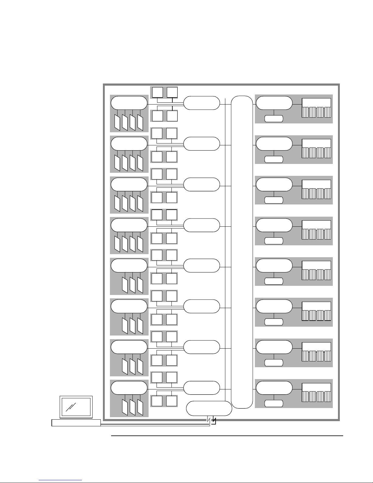
V2500/V2600 Crossbar Interconnection
The primary interconnecting component of each V2500/V2600 server
cabinet is the HyperPlane Crossbar, which provides connections from
processors and I/O to memory.
The V2500/V2600 crossbar is a non-blocking 8x8 crossbar, which
supports eight send messages and eight receive messages
simultaneously. This crossbar provides a central connection among the
processor agents, memory controllers, and PCI controllers within a
V2500/V2600 cabinet. On multiple-cabinet V2500/V2600 servers highspeed CTI interconnections provide access to “remote” memory or other
resources on remote cabinets. See “Multiple-Cabinet Server Connections”
on page 15 for multiple-cabinet information.
As Figure 7 on page 8 shows, the crossbar has four Exemplar Routing
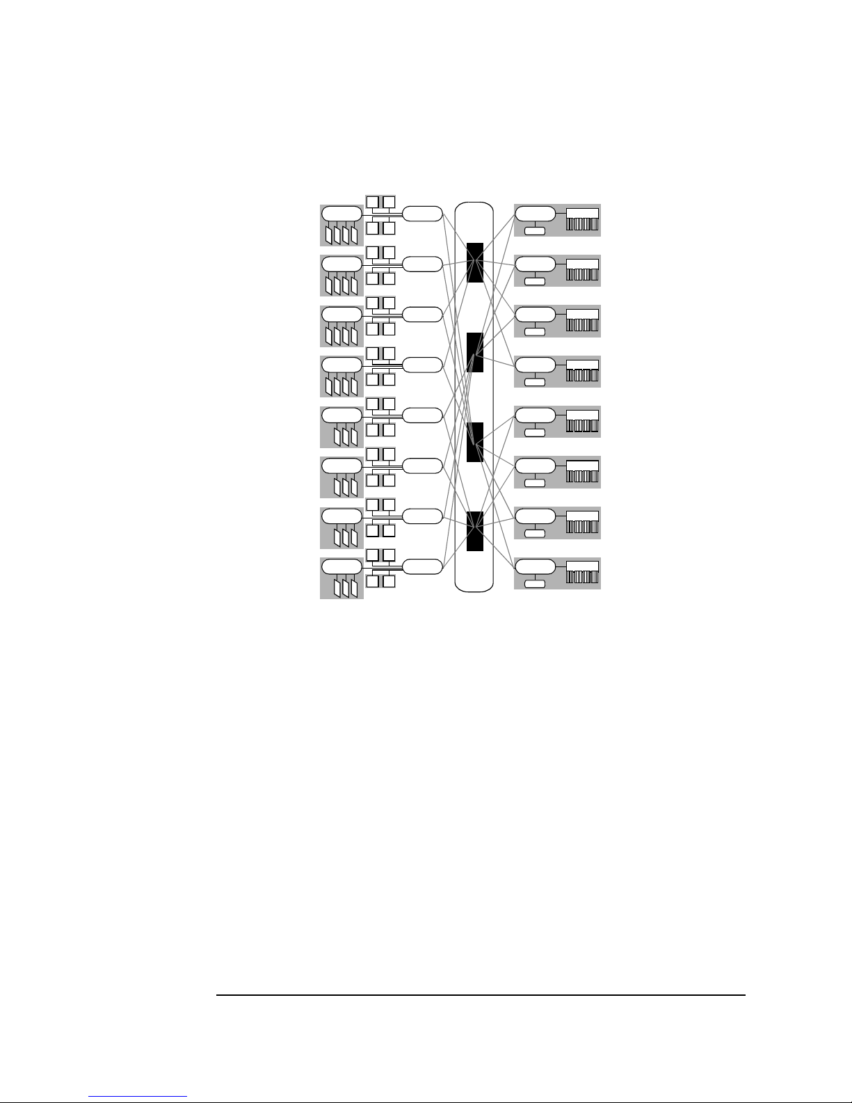
Access Controllers (ERACs), each of which connects to 4 processor agents
and four memory controllers. All memory controllers and processor
agents connect to two separate ERACs, thus making the entire system’s
memory addressable by all processors and I/O devices in the system.
6 Chapter 1
Overview
V-Class Server Architecture
Figure 6 Functional Diagram of a Single-Cabinet V2500/V2600 Server
CPU
CPU
PCI
Controller
I/O
I/O
I/O
PCI
Controller
I/O
I/O
I/O
PCI
Controller
I/O
I/O
I/O
PCI
Controller
I/O
I/O
I/O
PCI
Controller
I/O
I/O
PCI
Controller
I/O
I/O
PCI
Controller
I/O
I/O
PCI
Controller
I/O
I/O
Processor
Agent
CPU
CPU
I/O
CPU
CPU
Processor
Agent
CPU
CPU
I/O
CPU
CPU
Processor
Agent
CPU
CPU
I/O
CPU
CPU
Processor
Agent
CPU
CPU
I/O
CPU
CPU
Processor
Agent
CPU
CPU
I/O
CPU
CPU
HyperPlane Crossbar
Processor
Agent
CPU
CPU
I/O
CPU
CPU
Processor
Agent
CPU
CPU
I/O
CPU
CPU
Processor
Agent
CPU
CPU
I/O
Core Utilities
Board
Memory
Controller
CTI
Memory
Controller
CTI
Memory
Controller
CTI
Memory
Controller
CTI
Memory
Controller
CTI
Memory
Controller
CTI
Memory
Controller
CTI
Memory
Controller
CTI
Memory
Memory
Memory
Memory
Memory
Memory
Memory
Memory
SSP Workstation
Chapter 1 7
Overview
V-Class Server Architecture
Figure 7 V2500/V2600 HyperPlane Crossbar Connections
Each ERAC has 16 ports, 4 send and 4 receive on each side, which may
operate simultaneously.
V2500/V2600 Cabinet Components
The key components within a V2500/V2600 server cabinet include:
• “Core Utilities Board” on page 9
• “Processors” on page 9
•“Memory” on page9
• “Input/Output” on page 12
In Chapter 2, you can find details on the V2500/V2600 cabinet external
controls, such as the on/off key switch panel, and cabinet displays,
including the LCD and attention light.
8 Chapter 1
 Loading...