

HP 9000 Superdome SX2000, Integrity Superdome, 9000 Superdome, 9000 sx2000 Installation Manual

HP Installation Guide, HP Integrity
Superdome/sx2000 and HP 9000
Superdome/sx2000 Servers
HP Part Number: 5992-1042
Published: July 2011
Edition: 9

© Copyright 2006, 2011 Hewlett-Packard Development Company, L.P.
The information contained herein is subject to change without notice. The only warranties for HP products and services are set forth in the express
warranty statements accompanying such products and services. Nothing herein should be construed as constituting an additional warranty. HP shall
not be liable for technical or editorial errors or omissions contained herein. Intel, Pentium, Intel Inside, and the Intel Inside logo are trademarks or
registered trademarks of Intel Corporation or its subsidiaries in the United States and other countries.
Microsoft and Windows are U.S. registered trademarks of Microsoft Corporation.
UNIX is a registered trademark of The Open Group.
Warranty
To obtain a copy of the warranty for this product see the warranty information website:
http://h20341.www2.hp.com/integrity/w1/en/resources/warranty-information.html

About This Document
This document contains the installation procedures of the system and operating system specifics
for components in the system.
Intended Audience
This document is intended for HP trained Customer Support Consultants.
Document Organization
This document is organized as follows:
Chapter 1 This chapter describes how to unpack and inspect the system, set up the system,
connect the MP to the customer LAN, and how to complete the installation.
Typographic Conventions
The following typographic conventions are used in this document.
WARNING! Lists requirements that you must meet to avoid personal injury.
CAUTION: Provides information required to avoid losing data or to avoid losing system
functionality.
IMPORTANT: Provides essential information to explain a concept or to complete a task.
NOTE: Highlights useful information such as restrictions, recommendations, or important details
about HP product features.
• Commands and options are represented using this font.
• Text that you type exactly as shown is represented using this font.
• Text to be replaced with text that you supply is represented using this
font.
Example: “Enter the ls -l filename command” means you must replace filename with
your own text.
• Keyboard keys and graphical interface items (such as buttons, tabs, and menu items) are
represented using this font.
Examples: The Control key, the OK button, the General tab, the Options menu.
• Menu —> Submenu represents a menu selection you can perform.
Example: “Select the Partition —> Create Partition action” means you must select the Create
Partition menu item from the Partition menu.
• Example screen output is represented using this font.
Related Information
Further information on HP server hardware management, Microsoft® Windows®, and diagnostic
support tools are available through the following website links.
Website for HP Technical Documentation
This is the main website for HP technical documentation. See http://www.hp.com/go/bizsupport.
Intended Audience 3

Server Hardware Information
The following website offers more information http://www.hp.com/go/integrity_servers-docs . It
provides HP nPartition server hardware management information, including information on site
preparation, installation, and more.
Diagnostics and Event Monitoring: Hardware Support Tools
The following link contains comprehensive information about HP hardware support tools, including
online and offline diagnostics and event monitoring tools. This website has manuals, tutorials,
FAQs, and other reference material. See www.hp.com/go/bizsupport.
Website for HP Technical Support
HP's IT resource center is located at the following website: and provides comprehensive support
information for IT professionals on a wide variety of topics, including software, hardware, and
networking. .
http://www13.itrc.hp.com/service/home/home.do?admit
Publishing History
The document printing date and edition number indicate the document’s current edition and are
included in the following table. The printing date will change when a new edition is produced.
Document updates may be issued between editions to correct errors or document product changes.
The latest version of this document is available on line at:
www.hp.com/go/bizsupport
March 2006. . . . . . . . . . . . . . . . . . . . . . . . . . . . . . . . . . . . . . . . . . . . . . . . . . . .First Edition
September 2006. . . . . . . . . . . . . . . . . . . . . . . . . . . . . . . . . . . . . . . . . . . . . . . . . . . .Second Edition
February 2007. . . . . . . . . . . . . . . . . . . . . . . . . . . . . . . . . . . . . . . . . . . . . . . . . . . .Third Edition
November 2007. . . . . . . . . . . . . . . . . . . . . . . . . . . . . . . . . . . . . . . . . . . . . . . . . . . .Fourth Edition
September 2009. . . . . . . . . . . . . . . . . . . . . . . . . . . . . . . . . . . . . . . . . . . . . . . . . . . .Fifth Edition
March 2010. . . . . . . . . . . . . . . . . . . . . . . . . . . . . . . . . . . . . . . . . . . . . . . . . . . .Sixth Edition
August 2010. . . . . . . . . . . . . . . . . . . . . . . . . . . . . . . . . . . . . . . . . . . . . . . . . . . .Seventh Edition
April 2011. . . . . . . . . . . . . . . . . . . . . . . . . . . . . . . . . . . . . . . . . . . . . . . . . . . .Eighth Edition
July 2011. . . . . . . . . . . . . . . . . . . . . . . . . . . . . . . . . . . . . . . . . . . . . . . . . . . .Ninth Edition
HP contact information
For the name of the nearest HP authorized reseller:
• In the United States, see the HP US service locator website
http://welcome.hp.com/country/us/en/wwcontact.html.
• In other locations, see the Contact HP worldwide (in English) website:
http://welcome.hp.com/country/us/en/wwcontact.html.
For HP technical support:
• In the United States, for contact options see the Contact HP United States website:
http://welcome.hp.com/country/us/en/contact_us.html.
4

To contact HP by phone:
◦ Call 1-800-HP-INVENT (1-800-474-6836). This service is available 24 hours a day, 7
days a week. For continuous quality improvement, calls may be recorded or monitored.
◦ If you have purchased a Care Pack (service upgrade), call 1-800-633-3600. For more
information about Care Packs, see the HP website:
http://www.hp.com/hps.
• In other locations, see the Contact HP worldwide (in English) website:
http://welcome.hp.com/country/us/en/wwcontact.html.
Documentation feedback
HP welcomes your feedback. To make comments and suggestions about product documentation,
send a message to docsfeedback@hp.com.
Include the document title and manufacturing part number. All submissions become the property
of HP
Documentation feedback 5

1 Installing the System
This chapter describes installation of HP Integrity Superdome/sx2000 and HP 9000/sx2000
systems. Installers must have received adequate training, be knowledgeable about the product,
and have a good overall background in electronics and customer hardware installation.
Introduction
The instructions in this chapter are written for Customer Support Consultants (CSC) who are
experienced at installing complex systems. This chapter provides details about each step in the
sx2000 installation process. Some steps must be performed before others can be completed
successfully. To avoid undoing and redoing an installation step, follow the installation sequences
outlined in this chapter.
Communications Interference
HP system compliance tests are conducted with HP supported peripheral devices and shielded
cables, such as those received with the system. The system meets interference requirements of all
countries in which it is sold. These requirements provide reasonable protection against interference
with radio and television communications.
Installing and using the system in strict accordance with instructions provided by HP minimizes the
chances that the system will cause radio or television interference. However, HP does not guarantee
that the system will not interfere with radio and television reception.
Take the following precautions:
• Use only shielded cables.
• Install and route the cables according to the instructions provided.
• Ensure that all cable connector screws are firmly tightened.
• Use only HP supported peripheral devices.
• Ensure that all panels and cover plates are in place and secure before turning on the system.
Electrostatic Discharge
HP systems and peripherals contain assemblies and components that are sensitive to electrostatic
discharge (ESD).
CAUTION: Carefully observe the precautions and recommended procedures in this document to
prevent component damage from static electricity.
Take the following precautions:
• Always wear a grounded wrist strap when working on or around system components.
• Treat all assemblies, components, and interface connections as static-sensitive.
• When unpacking cards, interfaces, and other accessories that are packaged separately from
the system, keep the accessories in their non-conductive plastic bags until you are ready to
install them.
• Before removing or replacing any components or installing any accessories in the system,
select a work area in which potential static sources are minimized, preferably an antistatic
work station.
• Avoid working in carpeted areas and keep body movement to a minimum while installing
accessories.
6 Installing the System

Public Telecommunications Network Connection
Instructions are issued to the installation site that modems cannot be connected to public
telecommunications networks until full datacomm licenses are received for the country of installation.
Some countries do not require datacomm licenses. The product regulations engineer must review
beta site locations, and if datacomm licenses are not complete, ensure that the installation site is
notified officially and in writing that the product cannot be connected to public telecommunications
networks until the license is received.
Unpacking and Inspecting the System
This section describes what to do before unpacking the server and how to unpack the system itself.
WARNING! Do not attempt to move the cabinet, packed or unpacked, up or down an incline
of more than 15 degrees.
Verifying Site Preparation
Verifying site preparation includes gathering LAN information and verifying electrical requirements.
Gathering LAN Information
The Support Management Station (SMS) connects to the customer’s LAN. Determine the appropriate
IP address.
Verifying Electrical Requirements
The site must be verified for proper grounding and electrical requirements prior to the system being
shipped to the customer as part of the site preparation. Before unpacking and installing the system,
verify with the customer that grounding specifications and power requirements are met.
Checking the Inventory
The sales order packing slip lists all equipment shipped from HP. Use this packing slip to verify
that all equipment has arrived at the customer site.
NOTE: To identify each item by part number, see the sales order packing slip.
One of the large overpack containers is labeled “Open Me First.” This box contains the Solution
Information Manual and DDCAs. The unpacking instructions are in the plastic bag taped to the
cabinet.
The following items are in other containers. Check them against the packing list:
• Power distribution control assembly (PDCA) and power cord
• Two blower housings per cabinet
• Four blowers per cabinet
• Four side skins with related attachment hardware
• Cabinet blower bezels and front door assemblies
• Support Management Station
• Cables
• Optional equipment
• Boot device with the operating system installed
Unpacking and Inspecting the System 7
Inspecting the Shipping Containers for Damage
HP shipping containers are designed to protect their contents under normal shipping conditions.
After the equipment arrives at the customer site, carefully inspect each carton for signs of shipping
damage.
WARNING! Do not attempt to move the cabinet, packed or unpacked, up or down an incline
of more than 15 degrees.
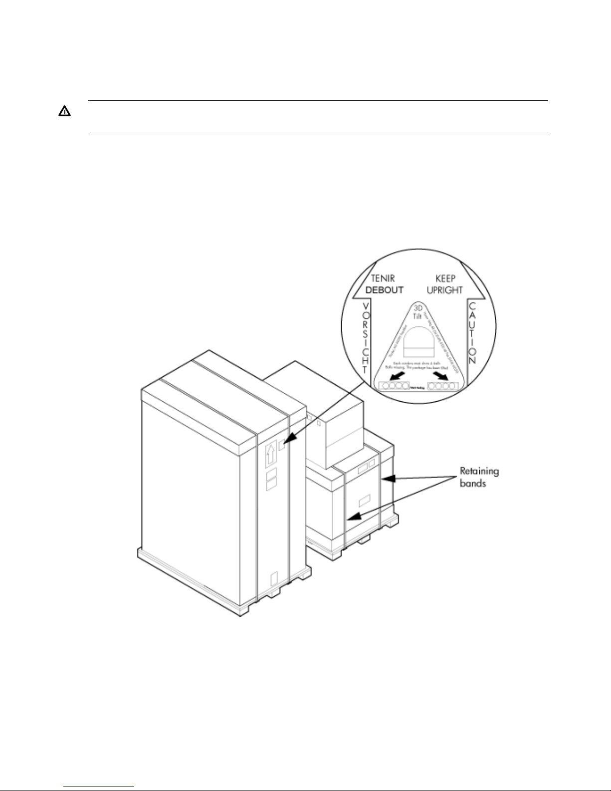
A tilt indicator is installed on the back and side of the cabinet shipping container (Figure 1
(page 8)). If the container is tilted to an angle that can cause equipment damage, the beads in
the indicator shift positions (Figure 2 (page 9)). If a carton has received a physical shock and
the tilt indicator is in an abnormal condition, visually inspect the unit for any signs of damage. If
damage is found, document the damage with photographs and contact the transport carrier
immediately.
Figure 1 Normal Tilt Indicator
8 Installing the System
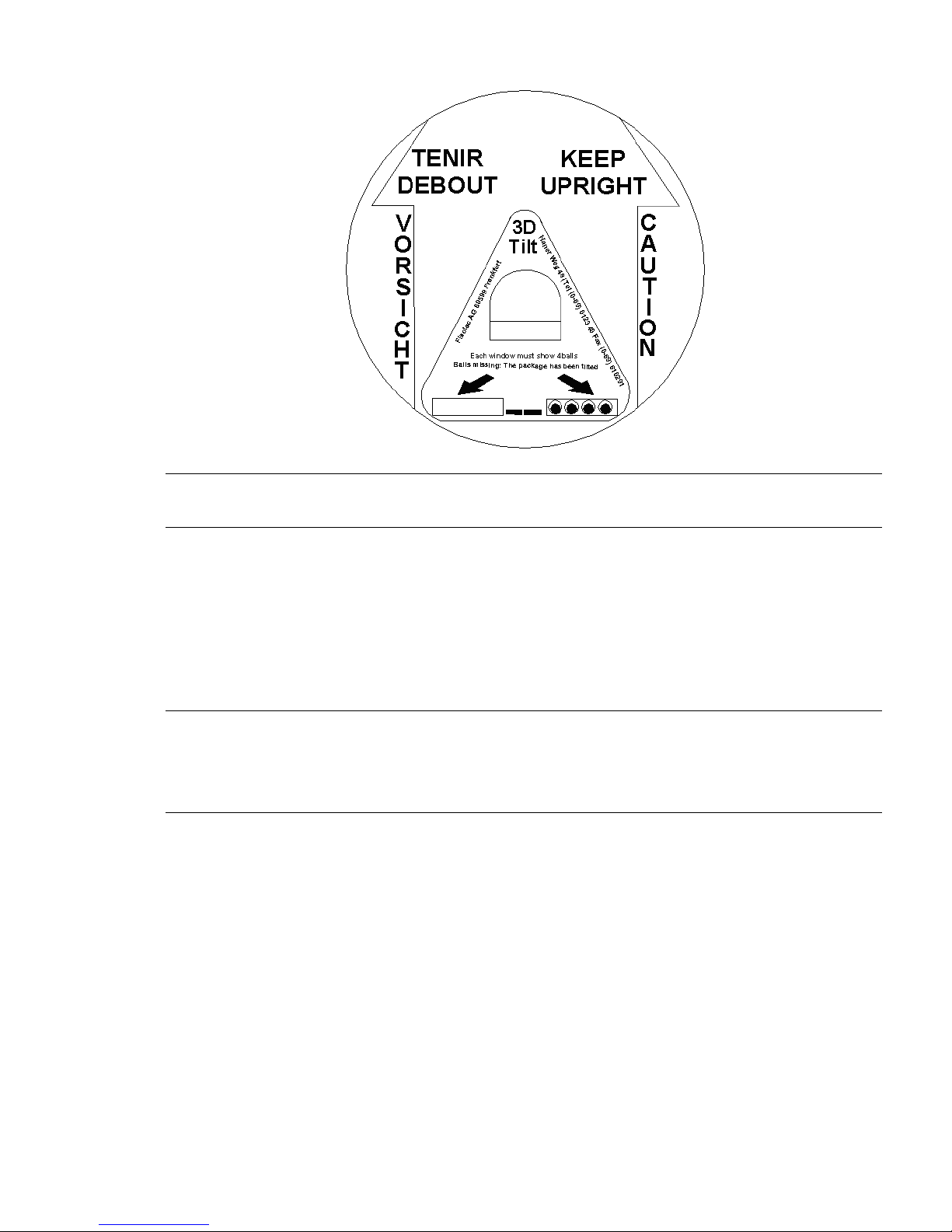
Figure 2 Abnormal Tilt Indicator
NOTE: If the tilt indicator shows that an abnormal shipping condition has occurred, write “possible
hidden damage” on the bill of lading and keep the packaging.
Inspection Precautions
• When the shipment arrives, check each container against the carrier's bill of lading. Inspect
the exterior of each container immediately for mishandling or damage during transit. If any
of the containers are damaged, request the carrier's agent be present when the container is
opened.
• When unpacking the containers, inspect each item for external damage. Look for broken
controls and connectors, dented corners, scratches, bent panels, and loose components.
NOTE: HP recommends keeping the shipping container and the packaging material. If it becomes
necessary to repackage the cabinet, the original packing material is necessary.
If discarding the shipping container or packaging material, dispose of them in an environmentally
responsible manner (recycle, if possible).
Claims Procedures
If the shipment is incomplete, if the equipment is damaged, or it fails to meet specifications, notify
the nearest HP Sales and Service Office. If damage occurred in transit, notify the carrier as well.
HP will arrange for replacement or repair without waiting for settlement of claims against the
carrier. In the event of damage in transit, retain the packing container and packaging materials
for inspection.
Unpacking and Inspecting Hardware Components
This section describes the procedures for opening the shipping container and unpacking and
inspecting the cabinet.
Unpacking and Inspecting the System 9

Tools Required
The following tools are required to unpack and install the system:
• Standard hand tools, such as a adjustable-end wrench
• ESD grounding strap
• Digital voltmeter capable of reading ac and dc voltages
• 1/2-inch socket wrench
• 9/16-inch wrench
• #2 Phillips screwdriver
• Flathead screwdriver
• Wire cutters or utility knife
• Safety goggles or glasses
• T-10, T-15, T-20, T-25, and T-30 Torx drivers
• 9-pin to 25-pin serial cable (HP part number 24542G)
• 9-pin to 9-pin null modem cable
Unpacking the Cabinet
WARNING! Use three people to unpack the cabinet safely.
HP recommends removing the cardboard shipping container before moving the cabinet into the
computer room.
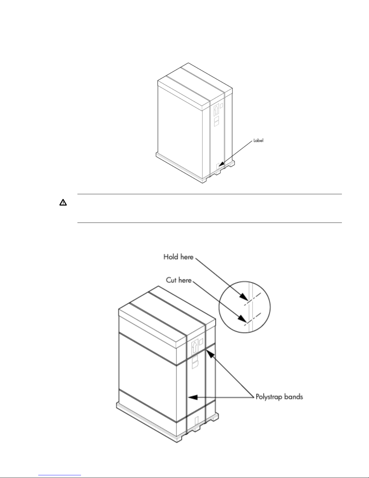
NOTE: If unpacking the cabinet in the computer room, be sure to position it so that it can be
moved into its final position easily. Notice that the front of the cabinet (Figure 3) is the side with
the label showing how to align the ramps.
To unpack the cabinet, follow these steps:
10 Installing the System
1. Position the packaged cabinet so that a clear area about three times the length of the package
(about 12 feet or 3.66 m) is available in front of the unit, and at least 2 feet (0.61 m) are
available on the sides.
Figure 3 Front of Cabinet Container
WARNING! Do not stand directly in front of the strapping while cutting it. Hold the band
above the intended cut and wear protective glasses. These bands are under tension. When
cut, they spring back and can cause serious eye injury.
2. Cut the plastic polystrap bands around the shipping container (Figure 4 (page 11)).
Figure 4 Cutting the Polystrap Bands
Unpacking and Inspecting the System 11
3. Lift the cardboard corrugated top cap off the shipping box.
4. Remove the corrugated sleeves surrounding the cabinet.
CAUTION: Cut the plastic wrapping material off rather than pulling it off. Pulling the plastic
covering off creates an ESD hazard to the hardware.
5. Remove the stretch wrap, the front and rear top foam inserts, and the four corner inserts from
the cabinet.
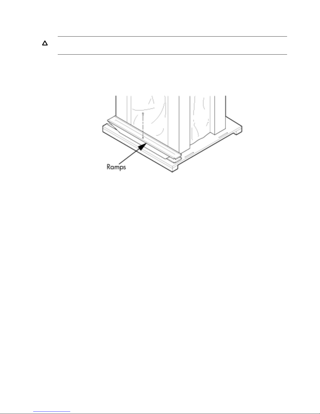
6. Remove the ramps from the pallet and set them aside (Figure 5 (page 12)).
Figure 5 Removing the Ramps from the Pallet
12 Installing the System
7. Remove the plastic antistatic bag by lifting it straight up off the cabinet. If the cabinet or any
components are damaged, follow the claims procedure. Some damage can be repaired by
replacing the damaged part. If you find extensive damage, you might need to repack and
return the entire cabinet to HP.
Inspecting the Cabinet
To inspect the cabinet exterior for signs of shipping damage, follow these steps:
1. Look at the top and sides for dents, warping, or scratches.
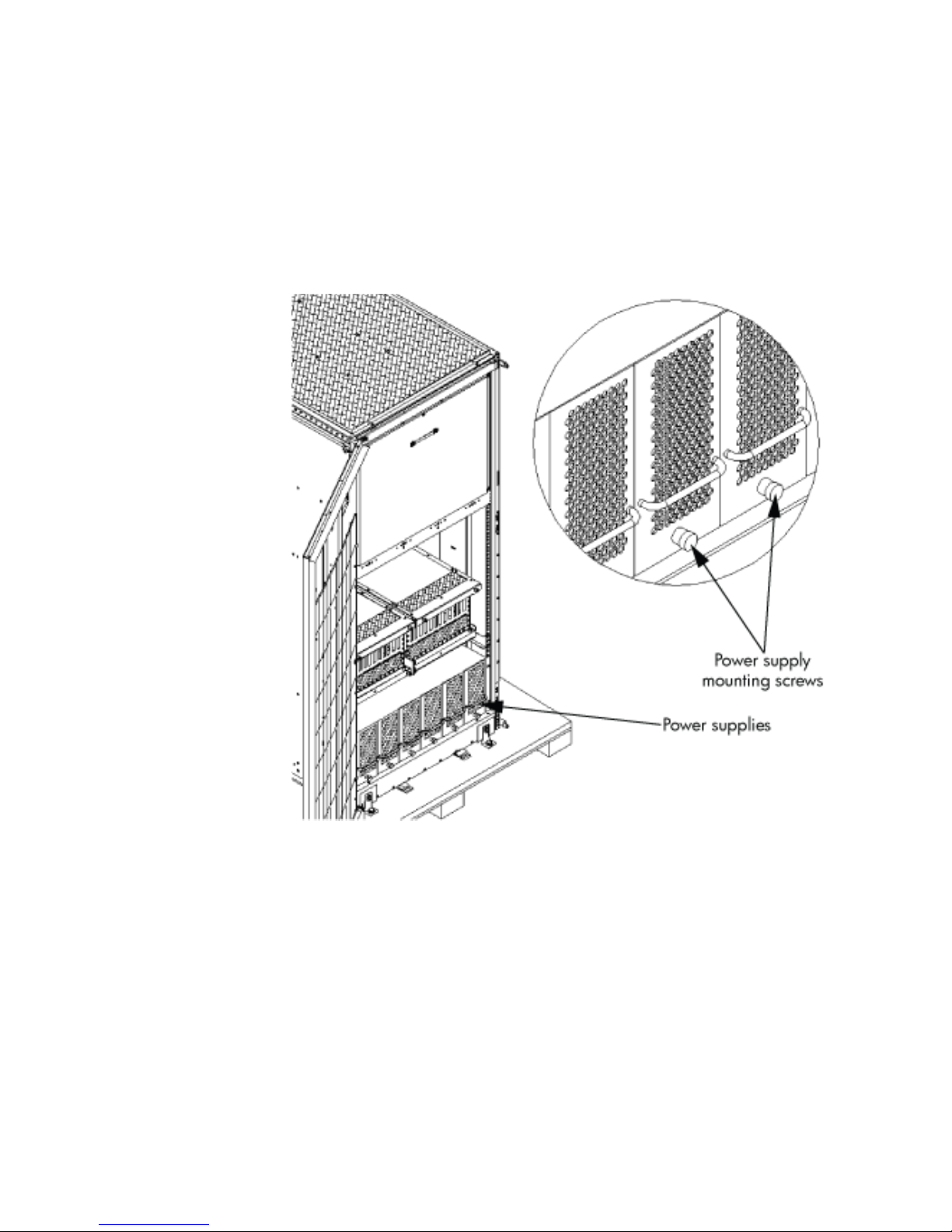
2. Verify that the power supply mounting screws are in place and locked (Figure 6).
Figure 6 Power Supply Mounting Screws Location
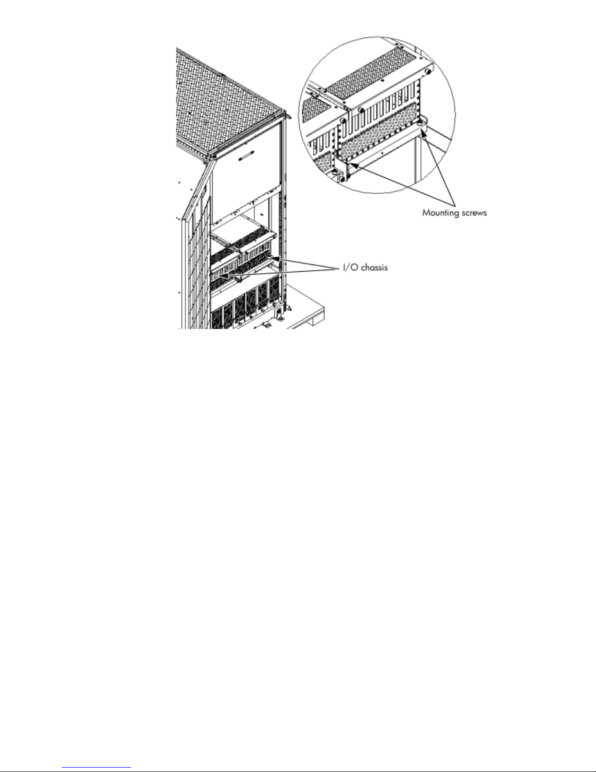
3. Verify that the I/O chassis mounting screws are in place and secure (Figure 7).
Inspect all components for signs of shifting during shipment or any signs of damage.
Figure 7 I/O Chassis Mounting Screws
Unpacking and Inspecting the System 13
14 Installing the System
Moving the Cabinet Off the Pallet
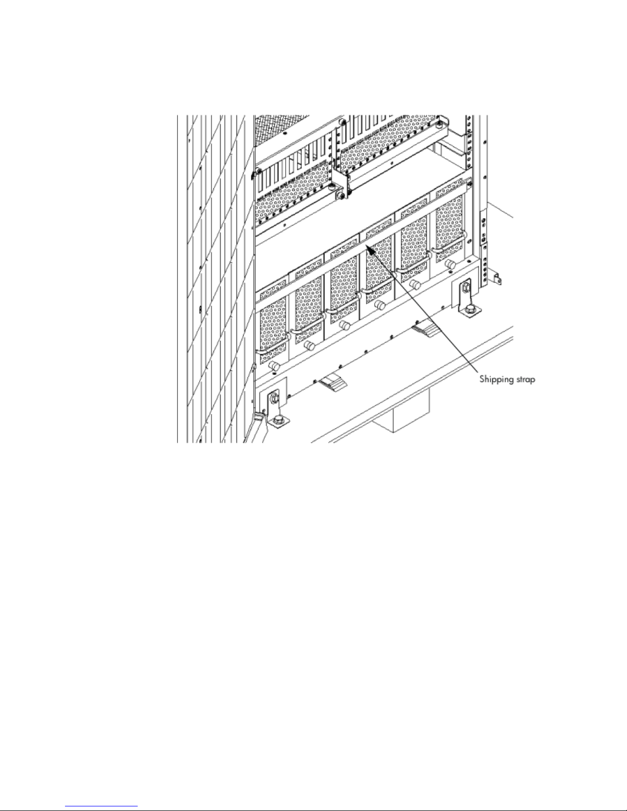
1. Remove the shipping strap that holds the BPSs in place during shipping (Figure 8 (page 15)).
Failure to remove the shipping strap will obstruct air flow into the BPS and FEPS.
Figure 8 Shipping Strap Location
2. Remove the pallet mounting brackets and pads on the side of the pallet where the ramp slots
are located (Figure 9).
Unpacking and Inspecting the System 15
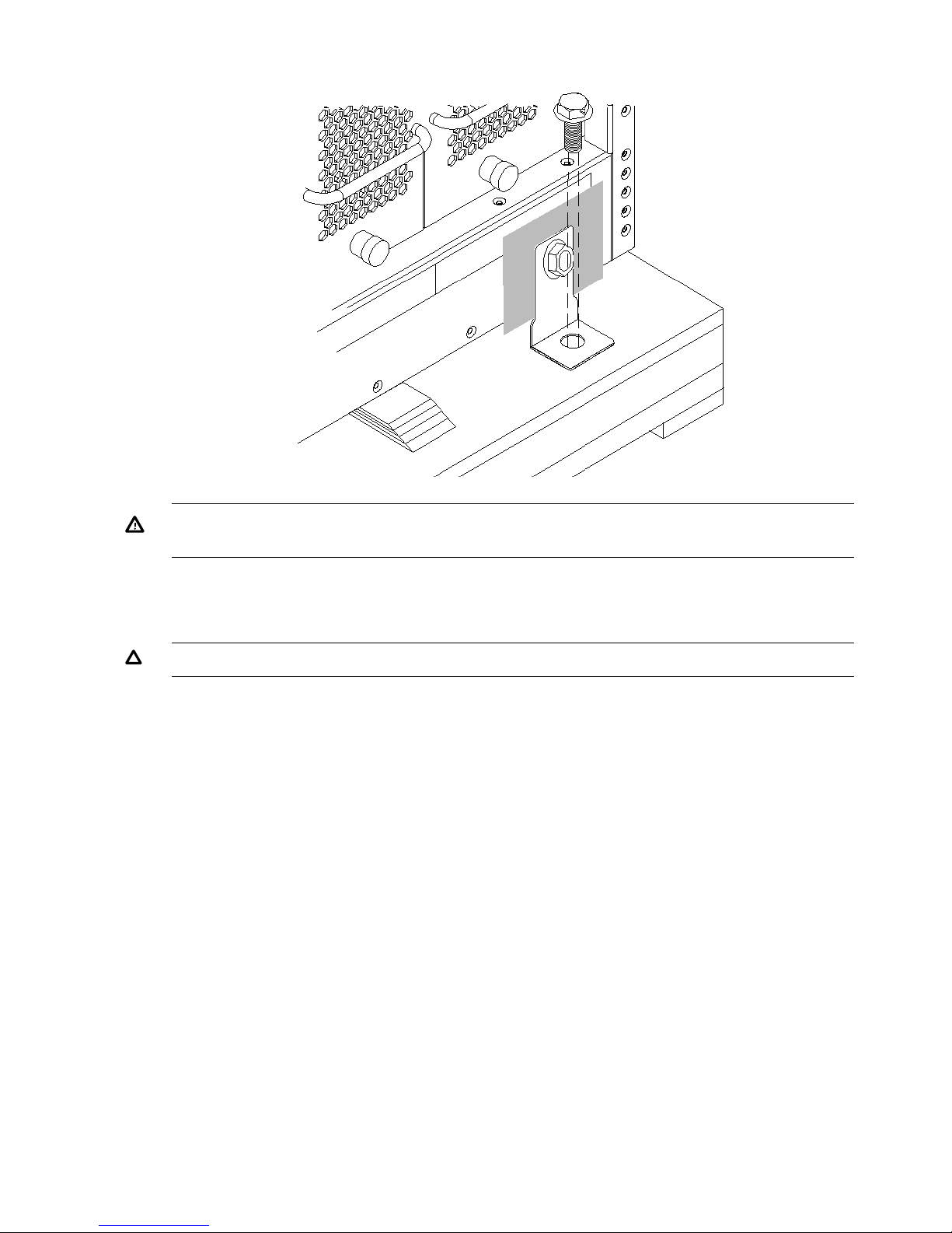
Figure 9 Removing the Mounting Brackets
WARNING! Do not remove the bolts on the mounting brackets that attach to the pallet. These
bolts prevent the cabinet from rolling off the back of the pallet.
3. On the other side of the pallet, remove only the bolt on each mounting bracket that is attached
to the cabinet.
4. Insert the ramps into the slots on the pallet.
CAUTION: Make sure the ramps are parallel and aligned (Figure 10).
The casters on the cabinet must roll unobstructed onto the ramp.
16 Installing the System
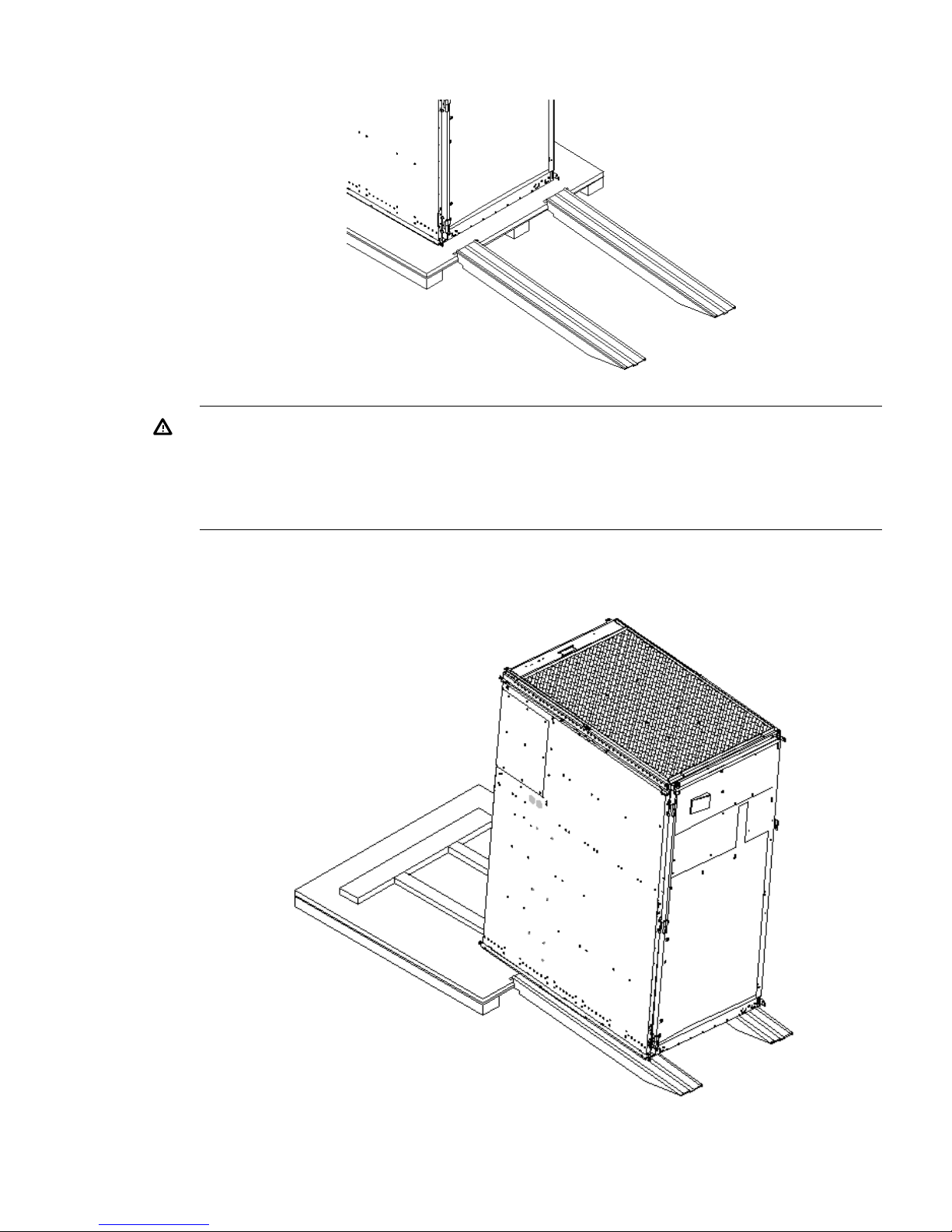
Figure 10 Positioning the Ramps
WARNING! Do not attempt to roll a cabinet without help. The cabinet can weigh as much
as 1400 pounds (635 kg). Three people are required to roll the cabinet off the pallet. Position
one person at the rear of the cabinet and one person on each side.
WARNING! Do not attempt to move the cabinet, either packed or unpacked, up or down
an incline of more than 15 degrees.
5. Carefully roll the cabinet down the ramp (Figure 11).
Figure 11 Rolling the Cabinet Down the Ramp
6. Unpack any other cabinets that were shipped.
Unpacking and Inspecting the System 17

Unpacking the PDCA
At least one PDCA ships with the system. In some cases, the customer might order two PDCAs, the
second to be used as a backup power source. Unpack the PDCA and ensure it has the power cord
option for installation.
Several power cord options are available for the PDCAs. Only options 6 and 7 are currently
available in new system configurations (Table 1 (page 18)). Table 2 (page 18) details options 6
and 7.
Table 1 Available Power Options
Power Receptacle RequiredInput Current Per
Phase 200 to 240 V
ac
1
PDCA
Required
Source Voltage
(Nominal)
Source
Type
Option
Connector and plug provided
with a 2.5 m (8.2 feet) power
cable. An electrician must
hardwire receptacle to 60 A site
power.
44 A maximum per
phase
4-wireVoltage range 200 to
240 V ac,
phase-to-phase, 50 Hz
/ 60 Hz
3-phase6
Connector and plug provided
with a 2.5 m (8.2 feet) power
cable. An electrician must
hardwire receptacle to 32 A site
power.
24 A maximum per
phase
5-wireVoltage range 200 to
240 V ac,
phase-to-neutral, 50 Hz
/ 60 Hz
3-phase7
1 A dedicated branch circuit is required for each PDCA installed.
Table 2 Power Cord Option 6 and 7 Details
Receptacle RequiredAttached PlugAttached Power CordPDCA Part Number
Mennekes ME 460R9
(60 A capacity)
Mennekes ME 460P9
(60 A capacity)
OLFLEX 190 (PN 600804) is a 2.5 meter
multiconductor, 600 V, 90˚C, UL and CSA
A5201-69023
(Option 6)
approved, oil resistant flexible cable. (8
AWG 60 A capacity)
Mennekes ME
532R6-1500 (32 A
capacity)
Mennekes ME
532P6-14 (32 A
capacity)
H07RN-F (OLFLEX PN 1600130) is a 2.5
meter heavy-duty neoprene jacketed
harmonized European flexible cable. (4
mm232 A capacity)
A5201-69024
(Option 7)
Returning Equipment
If the equipment is damaged, use the original packing material to repackage the cabinet for
shipment. If the packing material is not available, contact the local HP Sales and Support Office
regarding shipment.
Before shipping, place a tag on the container or equipment to identify the owner and the service
to be performed. Include the equipment model number and the full serial number, if applicable.
The model number and the full serial number are printed on the system information labels located
at the bottom front of the cabinet.
WARNING! Do not attempt to push the loaded cabinet up the ramp onto the pallet. Three people
are required to push the cabinet up the ramp and position it on the pallet. Inspect the condition of
the loading and unloading ramp before use.
Repackaging
To repackage the cabinet, follow these steps:
1. Assemble the HP packing materials that came with the cabinet.
2. Carefully roll the cabinet up the ramp.
3. Attach the pallet mounting brackets to the pallet and the cabinet.
18 Installing the System
4. Reattach the ramps to the pallet.
5. Replace the plastic antistatic bag and foam inserts.
6. Replace the cardboard surrounding the cabinet.
7. Replace the cardboard caps.
8. Secure the assembly to the pallet with straps.
The cabinet is now ready for shipment.
Setting Up the System
After a site is prepared, the system is unpacked, and all components are inspected, the system can
be prepared for booting.
Moving the System and Related Equipment to the Installation Site
Carefully move the cabinets and related equipment to the installation site but not into the final
location. If the system is to be placed at the end of a row, you must add side bezels before
positioning the cabinet in its final location. Check the path from where the system was unpacked
to its final destination to make sure the way is clear and free of obstructions.
WARNING! If the cabinet must be moved up ramps, be sure to maneuver it using three people.
Unpacking and Installing the Blower Housings and Blowers
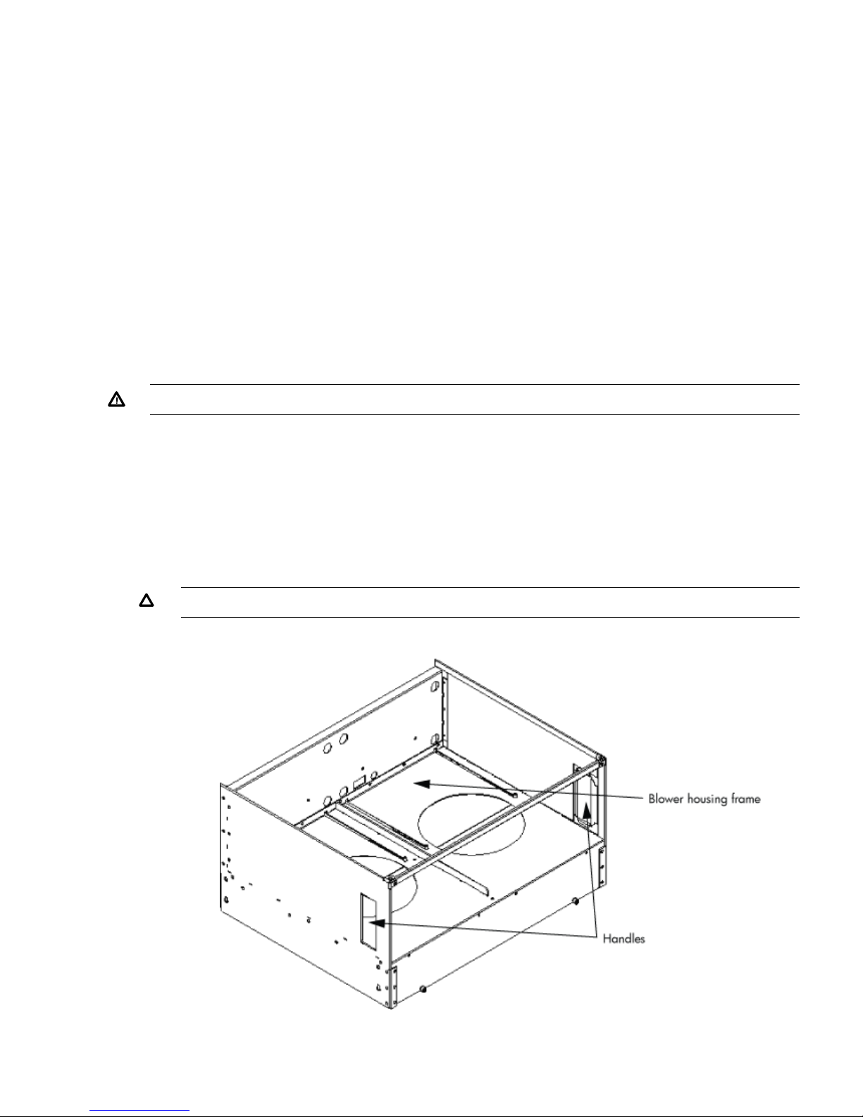
Each cabinet contains two blower housings and four blowers. Although similar in size, the blower
housings for each cabinet are not the same; one has a connector to which the other attaches. To
unpack and install the housings and blowers, follow these steps:
1. Unpack the housings from the cardboard box and set them aside.
The rear housing is labeled Blower 3 Blower 2. The front housing is labeled Blower 0 Blower
1.
CAUTION: Do not lift the housing by the frame (Figure 12).
Figure 12 Blower Housing Frame
Setting Up the System 19
 Loading...