

HP rp7440, Integrity rx7640, 9000 rp7440 Installation Manual

HP Integrity rx7640 and HP 9000 rp7440
Servers
Installation Guide
HP Part Number: AB312-9012A
Published: September 2007
Edition: 4

© Copyright 2007 Hewlett-Packard Development Company, L.P.
The information contained herein is subject to changewithoutnotice.The only warranties for HP products and services are set forth in the express
warranty statements accompanying such products and services. Nothing herein should be construed as constituting an additional warranty. HP
shall not be liable for technical or editorial errors or omissions contained herein. Intel, Pentium, Intel Inside, and the Intel Inside logo are trademarks
or registered trademarks of Intel Corporation or its subsidiaries in the United States and other countries.
© Copyright 2007 Hewlett-Packard Development Company, L.P.
The information contained herein is subject to change without notice.
The only warranties for HP products and services are set forth in the express warranty statements accompanying such products and services.
Nothing herein should be construed as constituting an additional warranty. HP shall not be liable for technical or editorial errors or omissions
contained herein.
Microsoft and Windows are U.S. registered trademarks of Microsoft Corporation. Linux is a U.S. registered trademark of Linus Torvalds. Intel
is a trademark or registered trademark of Intel Corporation or its susidaries in the United States and other countries.

Table of Contents
About This Document.........................................................................................................9
Intended Audience.................................................................................................................................9
Typographic Conventions......................................................................................................................9
Publishing History..................................................................................................................................9
Related Information..............................................................................................................................10
HP Encourages Your Comments..........................................................................................................11
1 HP Integrity rx7640 Server and HP 9000 rp7440 Server Overview.....................13
Detailed Server Description..................................................................................................................13
Dimensions and Components.........................................................................................................14
Front Panel.......................................................................................................................................17
Front Panel Indicators and Controls..........................................................................................17
Enclosure Status LEDs...............................................................................................................17
Cell Board........................................................................................................................................17
PDH Riser Board........................................................................................................................18
Central Processor Units..............................................................................................................19
Memory Subsystem....................................................................................................................19
DIMMs........................................................................................................................................20
Cells and nPartitions........................................................................................................................20
Internal Disk Devices for the Server................................................................................................21
System Backplane............................................................................................................................21
System Bacplane to PCI-X Backplane Connectivity...................................................................22
Clocks and Reset........................................................................................................................22
I/O Subsystem..................................................................................................................................22
PCI-X/PCIe Backplane................................................................................................................25
PCI-X/PCIe Slot Boot Paths...................................................................................................26
MP/SCSI Board...........................................................................................................................27
LAN/SCSI Board........................................................................................................................27
Mass Storage (Disk) Backplane..................................................................................................27
2 Installing the Server......................................................................................................29
Receiving and Inspecting the Server Cabinet.......................................................................................29
Unpacking the Server Cabinet.........................................................................................................29
Securing the Cabinet........................................................................................................................32
Standalone and To-Be-Racked Systems................................................................................................33
Rack-Mount System Installation.....................................................................................................33
Lifting the Server Cabinet Manually....................................................................................................33
Using the RonI Model 17000 SP 400 Lifting Device.............................................................................35
Wheel Kit Installation...........................................................................................................................38
Installing the Power Distribution Unit.................................................................................................43
Installing Additional Cards and Storage..............................................................................................44
Installing Additional Hard Disk Drives..........................................................................................44
Removable Media Drive Installation...............................................................................................45
PCI-X Card Cage Assembly I/O Cards............................................................................................46
Installing an Additional PCI-X Card..........................................................................................49
Installing an A6869B VGA/USB PCI Card in a Server....................................................................51
Troubleshooting the A6869B VGA/USB PCI Card..........................................................................52
No Console Display...................................................................................................................53
Reference URL............................................................................................................................53
Table of Contents 3

Cabling and Power Up..........................................................................................................................53
Checking the Voltage.......................................................................................................................53
Preface........................................................................................................................................53
Voltage Range Verification of Receptacle...................................................................................53
Verifying the Safety Ground (Single Power Source)..................................................................54
Verifying the Safety Ground (Dual Power Source)....................................................................55
Voltage Check (Additional Procedure)...........................................................................................57
Connecting AC Input Power...........................................................................................................58
Installing The Line Cord Anchor (for rack mounted servers).........................................................59
Two Cell Server Installation (rp7410, rp7420, rp7440, rx7620, rx7640)......................................59
Core I/O Connections......................................................................................................................60
MP/SCSI I/O Connections .........................................................................................................60
LAN/SCSI Connections..............................................................................................................61
Management Processor Access..................................................................................................61
Setting Up the Customer Engineer Tool (PC) .................................................................................61
Setting CE Tool Parameters........................................................................................................61
Connecting the CE Tool to the Local RS232 Port on the MP .....................................................62
Turning on Housekeeping Power and Logging in to the MP.........................................................62
Configuring LAN Information for the MP......................................................................................63
Accessing the Management Processor via a Web Browser.............................................................65
Verifying the Presence of the Cell Boards.......................................................................................66
System Console Selection................................................................................................................67
VGA Consoles............................................................................................................................68
Interface Differences Between Itanium-based Systems.............................................................68
Other Console Types..................................................................................................................68
Additional Notes on Console Selection.....................................................................................68
Configuring the Server for HP-UX Installation...............................................................................69
Booting the Server ...........................................................................................................................69
Selecting a Boot Partition Using the MP ...................................................................................70
Verifying the System Configuration Using the EFI Shell...........................................................70
Booting HP-UX Using the EFI Shell...........................................................................................70
Adding Processors with Instant Capacity.......................................................................................70
Installation Checklist.......................................................................................................................71
4 Table of Contents

List of Figures
1-1 8-Socket Server Block Diagram.....................................................................................................14
1-2 Server (Front View With Bezel) ....................................................................................................14
1-3 Server (Front View Without Bezel)................................................................................................15
1-4 Right-Front View...........................................................................................................................16
1-5 Left-Rear View ..............................................................................................................................17
1-6 Front Panel LEDs and Power Switch.............................................................................................17
1-7 Cell Board......................................................................................................................................18
1-8 CPU Locations on Cell Board........................................................................................................19
1-9 Memory Subsystem.......................................................................................................................20
1-10 Disk Drive and DVD Drive Location............................................................................................21
1-11 System Backplane Block Diagram.................................................................................................22
1-12 PCI-X Board to Cell Board Block Diagram....................................................................................23
2-1 Removing the Polystraps and Cardboard.....................................................................................30
2-2 Removing the Shipping Bolts and Plastic Cover...........................................................................31
2-3 Preparing to Roll Off the Pallet.....................................................................................................32
2-4 Securing the Cabinet......................................................................................................................33
2-5 Inserting Rear Handle Tabs into Chassis......................................................................................34
2-6 Attaching the Front of Handle to Chassis.....................................................................................35
2-7 RonI Lifter......................................................................................................................................36
2-8 Positioning the Lifter to the Pallet.................................................................................................37
2-9 Raising the Server Off the Pallet Cushions....................................................................................38
2-10 Component Locations ...................................................................................................................39
2-11 Left Foam Block Position...............................................................................................................40
2-12 Right Foam Block Position............................................................................................................40
2-13 Foam Block Removal.....................................................................................................................41
2-14 Attaching a Caster to the Server....................................................................................................42
2-15 Securing Each Caster Cover to the Server.....................................................................................43
2-16 Completed Server..........................................................................................................................43
2-17 Disk Drive and DVD Drive Location............................................................................................45
2-18 Removable Media Location...........................................................................................................46
2-19 PCI I/O Slot Details........................................................................................................................51
2-20 PCI/PCI-X Card Location..............................................................................................................52
2-21 Voltage Reference Points for IEC 320 C19 Plug.............................................................................54
2-22 Safety Ground Reference Check....................................................................................................55
2-23 Safety Ground Reference Check....................................................................................................56
2-24 Wall Receptacle Pinouts................................................................................................................57
2-25 AC Power Input Labeling..............................................................................................................58
2-26 Distribution of Input Power for Each Bulk Power Supply............................................................59
2-27 Two Cell Line Cord Anchor (rp7410, rp7420, rp7440, rx7620, rx7640).........................................60
2-28 Line Cord Anchor Attach Straps...................................................................................................60
2-29 Front Panel Display ......................................................................................................................62
2-30 MP Main Menu..............................................................................................................................63
2-31 The lc Command Screen................................................................................................................64
2-32 The ls Command Screen................................................................................................................65
2-33 Example sa Command...................................................................................................................66
2-34 Browser Window...........................................................................................................................66
2-35 The du Command Screen..............................................................................................................67
2-36 Console Output Device menu.......................................................................................................68
5

6

List of Tables
1-1 Cell Board CPU Module Load Order............................................................................................19
1-2 Server DIMMs...............................................................................................................................20
1-3 PCI-X paths for Cell 0....................................................................................................................23
1-4 PCI-X Paths Cell 1..........................................................................................................................23
1-5 PCI-X Slot Types............................................................................................................................25
1-6 PCI-X/PCIe Slot Types...................................................................................................................26
2-1 Wheel Kit Packing List..................................................................................................................38
2-2 Caster Part Numbers.....................................................................................................................41
2-3 HP Integrity rx7640 PCI-X I/O Cards............................................................................................46
2-4 Single Phase Voltage Examples.....................................................................................................54
2-5 Factory-Integrated Installation Checklist......................................................................................71
7

8
About This Document
This document covers the installation of HP Integrity rx7640 and HP 9000 rp7440 Servers.
This document does not describe system software or partition configuration in any detail. For
detailed information concerning those topics, refer to the HP System Partitions Guide:
Administration for nPartitions.
Intended Audience
This document is intended to be used by customer engineers assigned to install the HP Integrity
rx7640 and HP 9000 rp7440 Servers.
Typographic Conventions
This document uses the following typographical conventions:
WARNING! A warning lists requirements that you must meet to avoid personal injury.
CAUTION: A caution provides information required to avoid losing data or avoid losing system
functionality.
NOTE: A note highlights useful information such as restrictions, recommendations, or important
details about HP product features.
• Commands and options are represented using this font.
• Text that you type exactly as shown is represented using this font.
• Text to be replaced with text that you supply is represented using this font.
Example: “Enter the ls -l filename command” means you must replace filename with your
own text.
• Keyboard keys and graphical interface items (such as buttons, tabs, and menu items)
are represented using this font.
Examples: The Control key, the OK button, the General tab, the Options menu.
• Menu —> Submenu represents a menu selection you can perform.
Example: “Select the Partition —> Create Partition action” means you must select the
Create Partition menu item from the Partition menu.
• Example screen output is represented using this font.
Publishing History
The Printing History below identifies the edition dates of this document. Updates are made to
this publication on an unscheduled, as needed, basis. The updates will consist of a complete
replacement document and pertinent on-line or CD-ROM documentation.
March 2006. . . . . . . . . . . . . . . . . . . . . . . . . . . . . . . . . . . . . . . . . . . . . . . . .First Edition
September 2006. . . . . . . . . . . . . . . . . . . . . . . . . . . . . . . . . . . . . . . . . . . . . . . .Second Edition
January 2007Minor edits throughout.Third Edition
September 2007Minor edits.Fourth Edition
Intended Audience 9
Related Information
You can access other information on HP server hardware management, Microsoft® Windows®
administration, and diagnostic support tools at the following Web sites:
http://docs.hp.com The main Web site for HP technical documentation is http://docs.hp.com.
Server Hardware Information: http://docs.hp.com/hpux/hw/ The
http://docs.hp.com/hpux/hw/ Web site is the systems hardware portion of docs.hp.com.
10 About This Document

It provides HP nPartition server hardware management information, including site preparation,
installation, and more.
Windows Operating System Information You can find information about administration of the
Microsoft® Windows® operating system at the following Web sites, among others:
• http://docs.hp.com/windows_nt/
• http://www.microsoft.com/technet/
Diagnostics and Event Monitoring: Hardware Support Tools Complete information about HP
hardware support tools, including online and offline diagnostics and event monitoring tools, is
at the http://docs.hp.com/hpux/diag/ Web site. This site has documents, tutorials, FAQs,
and other reference material.
Web Site for HP Technical Support: http://us-support2.external.hp.com HP IT resource center
Web site at http://us-support2.external.hp.com/ provides comprehensive support
information for IT professionals on a wide variety of topics, including software, hardware, and
networking.
Books about HP-UX Published by Prentice Hall The http://www.hp.com/hpbooks/ Web
site lists the HP books that Prentice Hall currently publishes, such as HP-UX books including:
• HP-UX 11i System Administration Handbook and
Toolkithttp://www.hp.com/hpbooks/prentice/ptr_0130600814.html
• HP-UX Virtual
Partitionshttp://www.hp.com/hpbooks/prentice/ptr_0130352128.html
HP books are available worldwide through bookstores, online booksellers, and office and
computer stores.
HP Encourages Your Comments
HP encourages your comments concerning this document. We are committed to providing
documentation that meets your needs. Send any errors found, suggestions for improvement, or
compliments to:
feedback@fc.hp.com
Include the document title, manufacturing part number, and any comment, error found, or
suggestion for improvement you have concerning this document.
HP Encourages Your Comments 11

12
1 HP Integrity rx7640 Server and HP 9000 rp7440 Server
Overview
The HP Integrity rx7640 and HP 9000 rp7440 Servers are members of HP’s business-critical
computing platform family in the mid-range product line.
The information in chapters one through six of this guide applies to the HP Integrity rx7640 and
HP 9000 rp7440 Servers, except for a few items specifically denoted as applying only to the HP
Integrity rx7640 Server. Chapter seven covers any information specific to the HP 9000 rp7440
Server only.
IMPORTANT: Ensure a valid UUID is either in place or available prior to maintenance of these
servers. This step is vital when performing upgrades and is recommended for existing hardware
service restoration. Specific information for upgrades is found in the Upgrade Guide, Mid-Range
Two-Cell HP Servers to HP Integrity rx7640 Server, located at the following
URL:http://docs.fc.hp.com.
The server is a 10U1high, 8-socket symmetric multiprocessor (SMP) rack-mount or standalone
server. Features of the server include:
• Up to 256 GB of physical memory provided by dual inline memory modules (DIMMs).
• Dual-core processors.
• Up to 16 processors with a maximum of 4 processor modules per cell board and a maximum
of 2 cell boards.
• One cell controller (CC) per cell board.
• Turbo fans to cool CPUs and CCs on the cell boards.
• Up to four embedded hard disk drives.
• One half-height DVD drive, two slimline DVDs or one DAT drive.
• Two front chassis mounted N+1 fans.
• Two rear chassis mounted N+1 fans.
• Six N+1 PCI-X card cage fans.
• Two N+1 bulk power supplies.
• N+1 hot-swappable system oscillators.
• Sixteen PCI slots divided into two IO Chassis each. Each IO Chassis accommodates eight
slots supporting PCI/PCI-X/PCI-X 2.0 device adapters or four PCI/PCI-X/PCI-X 2.0 and four
PCIe device adapters.
• Up to two core I/O card sets.
• One manageability processor per core I/O card with failover capability when two or more
core I/O cards are installed and properly configured.
• Four 220 V AC power plugs. Two are required and the other two provide power source
redundancy.
Detailed Server Description
The following section provides detailed information about the server components.
1. The U is a unit of measurement specifying product height. One U is equal to 1.75 inches.
Detailed Server Description 13
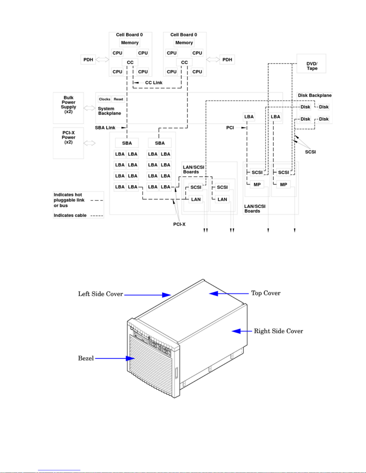
Figure 1-1 8-Socket Server Block Diagram
Dimensions and Components
The following section describes server dimensions and components.
Figure 1-2 Server (Front View With Bezel)
14 HP Integrity rx7640 Server and HP 9000 rp7440 Server Overview
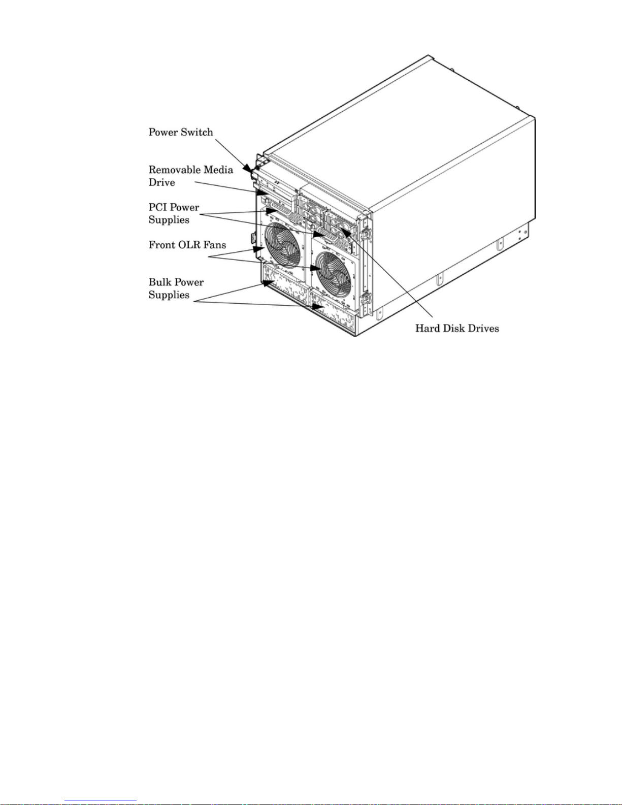
Figure 1-3 Server (Front View Without Bezel)
The server has the following dimensions:
• Depth: Defined by cable management constraints to fit into standard 36-inch deep rack:
25.5 inches from front rack column to PCI connector surface
26.7 inches from front rack column to MP Core I/O connector surface
30 inches overall package dimension, including 2.7 inches protruding in front of the front
rack columns.
• Width: 44.45 cm (17.5 inches), constrained by EIA standard 19 inch racks.
• Height: 10U – 0.54 cm = 43.91 cm (17.287 inches). This is the appropriate height for a product
that consumes 10U of rack height while allowing adequate clearance between products
directly above and below this product. Fitting four server units per 2 m rack and upgrade
of current 10U height products in the future are the main height constraints.
The mass storage section located in the front enables access to the 3.5-inch hard drives without
removal of the bezel. This is especially helpful when the system is mounted in the lowest position
in a rack. The mass storage bay also accommodates one 5.25-inch removable media device. The
front panel display board, containing LEDs and the system power switch, is located directly
above the 5.25-inch removable media bay.
Below the mass storage section and behind the removable front bezel are two, N+1 PCI-X power
supplies.
The bulk power supply section is partitioned by a sealed metallic enclosure located in the bottom
of the package. This enclosure houses the N+1 fully redundant BPSs. Install these power supplies
from the front of the server after removing the front bezel.
Detailed Server Description 15
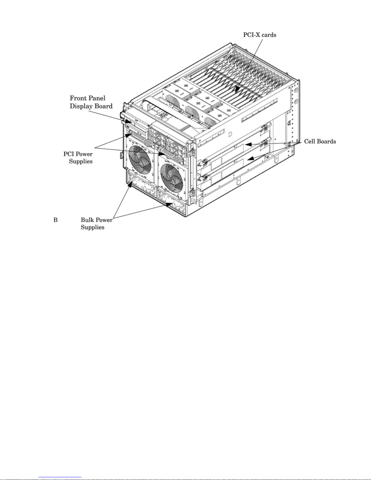
Figure 1-4 Right-Front View
Access the PCI-X card section, located toward the rear, by removing the top cover.
The PCI card bulkhead connectors are located at the rear top.
The PCI OLR fan modules are located in front of the PCI-X cards. These six 9.2-cm fans are housed
in plastic carriers. They are configured in two rows of three fans.
Four OLR system fan modules, externally attached to the chassis, are 15-cm (6.5-inch) fans. Two
fans are mounted on the front surface of the chassis and two are mounted on the rear surface.
The cell boards are accessed from the right side of the chassis behind a removable side cover.
The two MP/SCSI boards are positioned vertically at the rear of the chassis.
The two hot-pluggable N+1 redundant bulk power supplies provide a wide input voltage range.
They are installed in the front of the chassis, directly under the front fans.
A cable harness that connects from the rear of the BPSs to the system backplane provides DC
power distribution.
Access the system backplane by removing the left side cover. The system backplane hinges from
the lower edge and is anchored at the top with two jack screws.
The SCSI ribbon-cable assembly routes from the mass storage area to the backside of the system
backplane for connection to the MP/SCSI card, and to the AB290A LAN/SCSI PCI-X cards.
16 HP Integrity rx7640 Server and HP 9000 rp7440 Server Overview
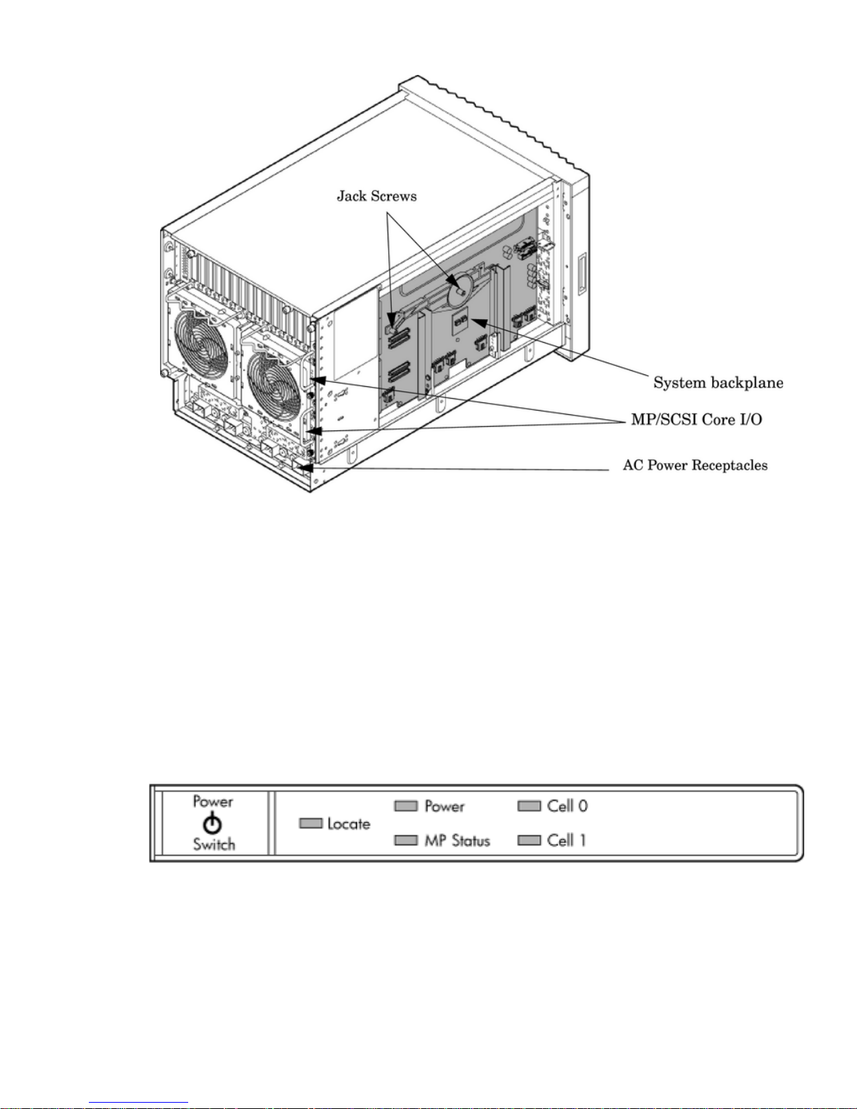
Figure 1-5 Left-Rear View
Front Panel
Front Panel Indicators and Controls
The front panel, located on the front of the server, includes the power switch. See Figure 1-6
Enclosure Status LEDs
The following status LEDs are on the front panel:
• Locate LED (blue)
• Power LED (tri-color)
• Management processor (MP) status LED (tri-color)
• Cell 0, 1 status (tri-color) LEDs
Figure 1-6 Front Panel LEDs and Power Switch
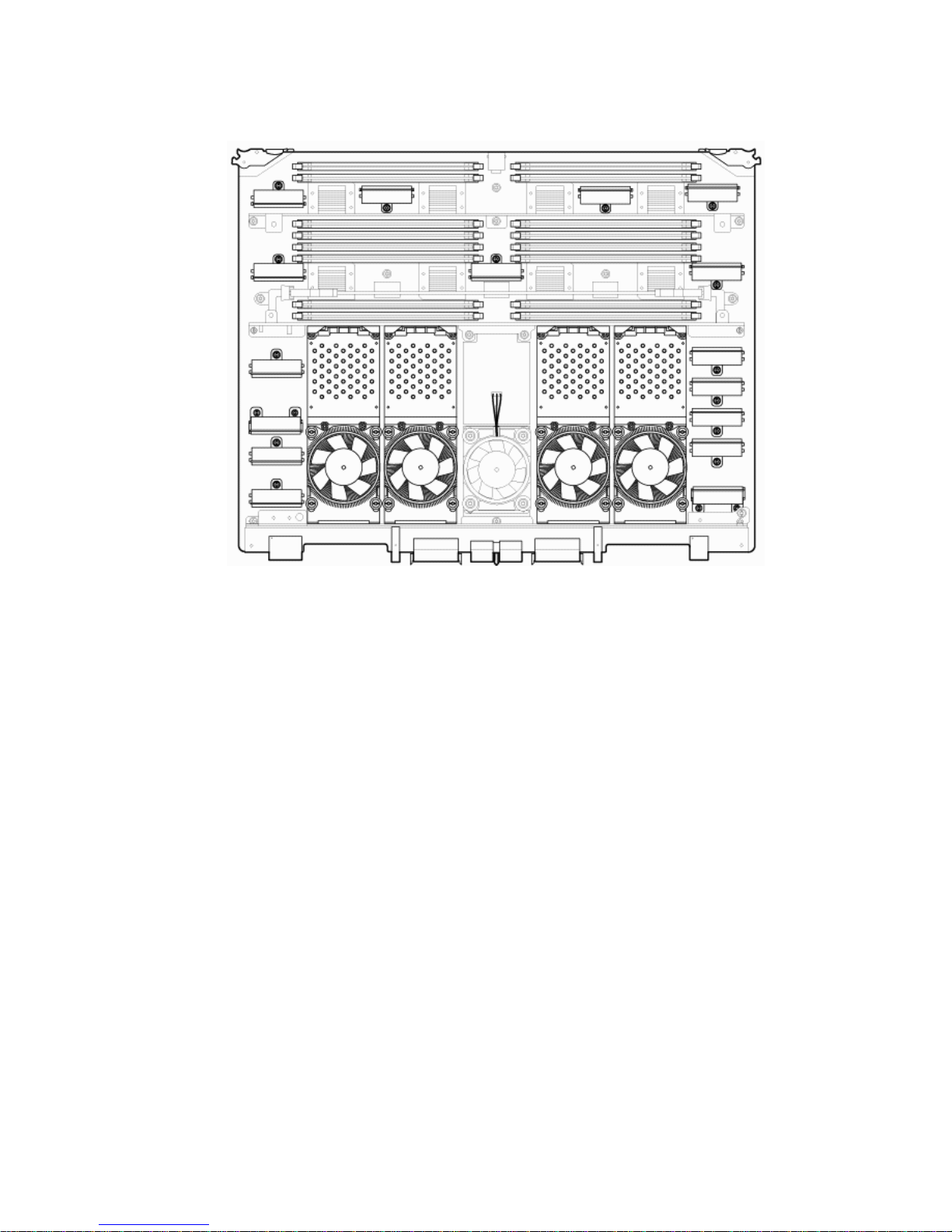
Cell Board
The cell board, illustrated in Figure 1-7, contains the processors, main memory, and the CC
application specific integrated circuit (ASIC) which interfaces the processors and memory with
the I/O, and to the other cell board in the server. The CC is the heart of the cell board, enabling
communication with the other cell board in the system. It connects to the processor dependent
hardware (PDH) and micro controller hardware. Each cell board holds up to two processor
modules and 16 memory DIMMs. One or two cell boards can be installed in the server. A cell
Detailed Server Description 17
board can be selectively powered off for adding processors, memory, or for maintenance of the
cell board, without affecting the other cell board in a configured partition.
Figure 1-7 Cell Board
The server has a 48 V distributed power system and receives the 48 V power from the system
backplane board. The cell board contains DC-to-DC converters to generate the required voltage
rails. The DC-to-DC converters on the cell board do not provide N+1 redundancy.
The cell board contains the following major buses:
• Two front side buses (FSB), each with up to two processors
• Four memory buses (one going to each memory quad)
• Incoming and outgoing I/O bus that goes off board to an SBA chip
• Incoming and outgoing crossbar bus that goes off board to the other cell board
• PDH bus that goes to the PDH and microcontroller circuitry
All of these buses come together at the CC chip.
Because of space limitations on the cell board, the PDH and microcontroller circuitry resides on
a riser board that plugs into the cell board at a right angle. The cell board also includes clock
circuits, test circuits, and de-coupling capacitors.
PDH Riser Board
The PDH riser board is a small card that plugs into the cell board at a right angle. The PDH riser
interface contains the following components:
• Microprocessor memory interface microcircuit
• Hardware including the processor dependant code (PDH) flash memory
• Manageability microcontroller with associated circuitry
The PDH obtains cell board configuration information from cell board signals and from the cell
board local power module (LPM).
18 HP Integrity rx7640 Server and HP 9000 rp7440 Server Overview
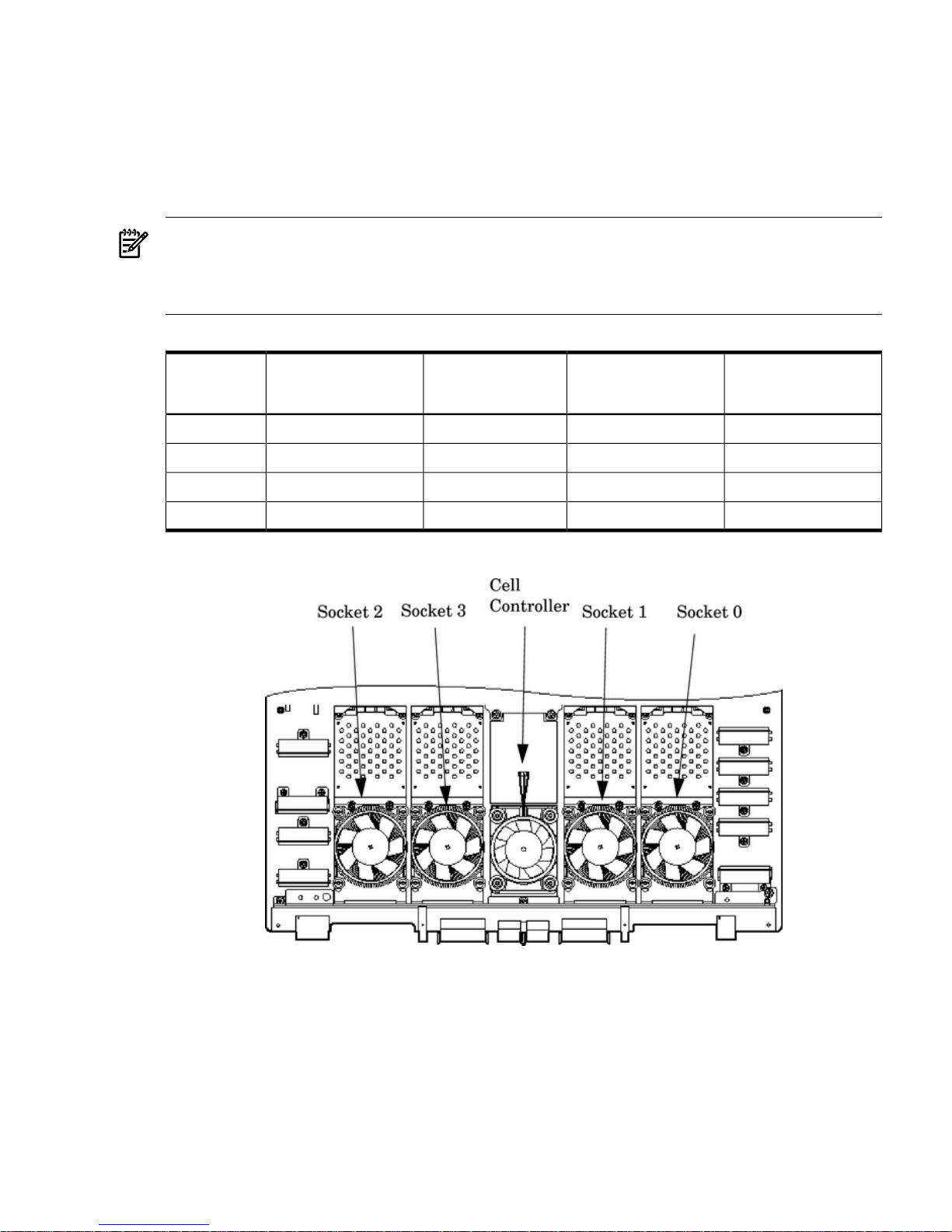
Central Processor Units
The cell board can hold up to four CPU modules. Each CPU module can contain up to two CPU
cores on a single socket. Modules are populated in increments of one. On a cell board, the
processor modules must be the same family, type, and clock frequencies. Mixing of different
processors on a cell board or partition is not supported. Refer to Table 1-1 for the load order that
must be maintained when adding processor modules to the cell board. Refer to Figure 1-8 for
the locations on the cell board for installing processor modules.
NOTE: Unlike previous HP cell based systems, the HP Integrity rx7640 server cell board does
not require that a termination module be installed at the end of an unused FSB. System firmware
is allowed to disable an unused FSB in the CC. This enables both sockets of the unused bus to
remain unpopulated.
Table 1-1 Cell Board CPU Module Load Order
Socket 0Socket 1Socket 3Socket 2Number of
CPU Modules
Installed
CPU installedEmpty slotEmpty slotEmpty slot1
CPU installedEmpty slotEmpty slotCPU installed2
CPU installedCPU installedEmpty slotCPU installed3
CPU installedCPU installedCPU installedCPU installed4
Figure 1-8 CPU Locations on Cell Board
Memory Subsystem
Figure 1-9 shows a simplified view of the memory subsystem. It consists of two independent
access paths, each path having its own address bus, control bus, data bus, and DIMMs . Address
and control signals are fanned out through register ports to the synchronous dynamic random
access memory (SDRAM) on the DIMMs.
The memory subsystem comprises four independent quadrants. Each quadrant has its own
memory data bus connected from the cell controller to the two buffers for the memory quadrant.
Each quadrant also has two memory control buses; one for each buffer.
Detailed Server Description 19
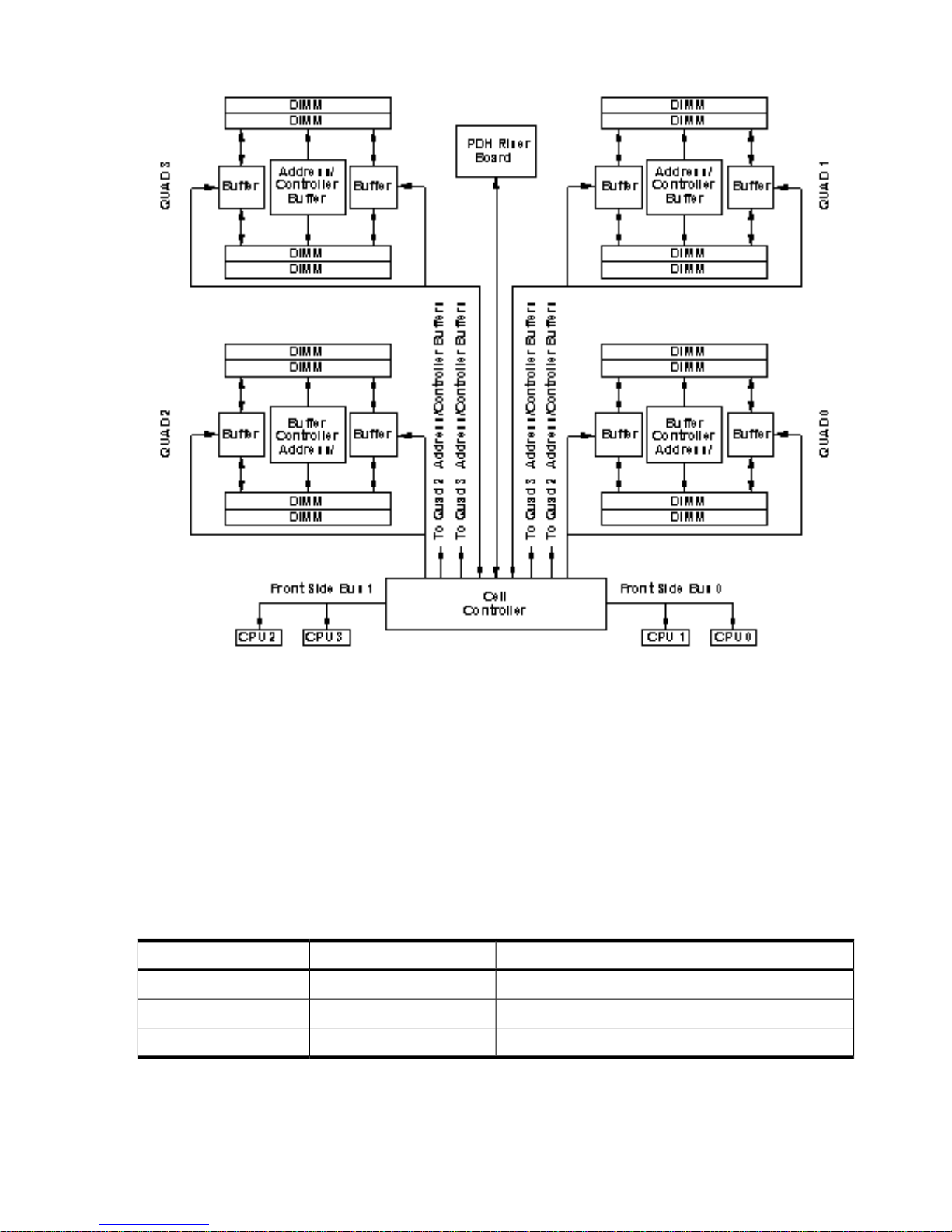
Figure 1-9 Memory Subsystem
DIMMs
The memory DIMMs used by the server are custom designed by HP. Each DIMM contains DDR-II
SDRAM memory that operates at 533 MT/s. Industry standard DIMM modules do not support
the high availability and shared memory features of the server. Therefore, industry standard
DIMM modules are not supported.
The server supports DIMMs with densities of 1, 2, and 4 Gb. Table 1-2 (page 20) lists each
supported DIMM size, the resulting total system capacity, and the memory component density.
Each DIMM is connected to two buffer chips on the cell board.
See Appendix C for more information on DIMM slot mapping and valid memory configurations.
Table 1-2 Server DIMMs
Memory Component DensityTotal CapacityDIMM Size
128 Mb32 Gb1 Gb
256 Mb64 Gb2 Gb
512 Mb128 Gb4 Gb
Cells and nPartitions
An nPartition comprises one or more cells working as a single system. Any I/O chassis that is
attached to a cell belonging to an nPartition is also assigned to the nPartition. Each I/O chassis
has PCI card slots, I/O cards, attached devices, and a core I/O card assigned to the I/O chassis.
20 HP Integrity rx7640 Server and HP 9000 rp7440 Server Overview
On the server, each nPartition has its own dedicated portion of the server hardware which can
run a single instance of the operating system. Each nPartition can boot, reboot, and operate
independently of any other nPartitions and hardware within the same server complex.
The server complex includes all hardware within an nPartition server: all cabinets, cells, I/O
chassis, I/O devices and racks, management and interconnecting hardware, power supplies, and
fans.
A server complex can contain one or two nPartitions, enabling the hardware to function as a
single system or as multiple systems.
NOTE: Partition configuration information is available on the Web at:
http://docs.hp.com
Refer to HP System Partitions Guide: Administration for nPartitions for details.
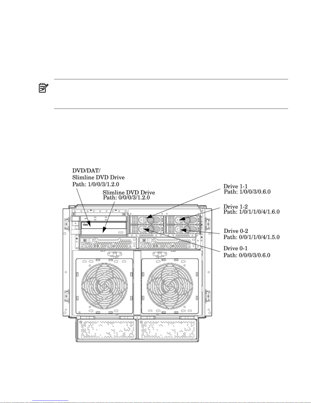
Internal Disk Devices for the Server
As Figure 1-10 shows, in a server cabinet, the top internal disk drives connect to cell 1 through
the core I/O for cell 1. Both of the bottom disk drives connect to cell 0 through the core I/O for
cell 0.
The DVD/DAT drive connects to cell 1 through the core I/O card for cell 1.
Figure 1-10 Disk Drive and DVD Drive Location
System Backplane
The system backplane contains the following components:
• The system clock generation logic
• The system reset generation logic
Detailed Server Description 21
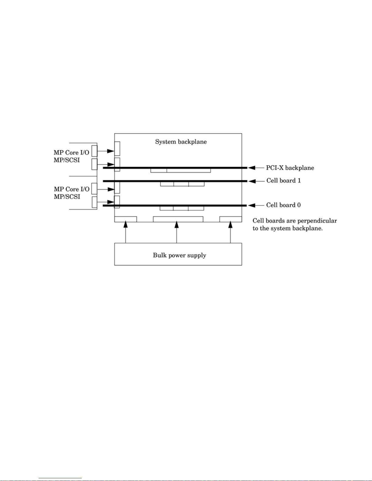
• DC-to-DC converters
• Power monitor logic
• Two local bus adapter (LBA) chips that create internal PCI buses for communicating with
the core I/O card
The backplane also contains connectors for attaching the cell boards, the PCI-X backplane, the
core I/O board set, SCSI cables, bulk power, chassis fans, the front panel display, intrusion
switches, and the system scan card. Unlike Superdome or the HP Integrity rx8640, there are no
Crossbar Chips (XBC) on the system backplane. The “crossbar-less” back-to-back CC connection
increases performance.
Only half of the core I/O board set connects to the system backplane. The MP/SCSI boards plug
into the backplane, while the LAN/SCSI boards plug into the PCI-X backplane.
Figure 1-11 System Backplane Block Diagram
System Bacplane to PCI-X Backplane Connectivity
The PCI-X backplane uses two connectors for the SBA link bus and two connectors for the high
speed data signals and the manageability signals.
SBA link bus signals are routed through the system backplane to the cell controller on each
corresponding cell board.
The high speed data signals are routed from the SBA chips on the PCI-X backplane to the two
LBA PCI bus controllers on the system backplane.
Clocks and Reset
The system backplane contains reset and clock circuitry that propagates through the whole
system. The system backplane central clocks drive all major chip set clocks. The system central
clock circuitry features redundant, hot-swappable oscillators.
I/O Subsystem
The cell board to the PCI-X board path runs from the CC to the SBA, from the SBA to the ropes,
from the ropes to the LBA, and from the LBA to the PCI slots seen in Figure 1-12. The CC on cell
board 0 and cell board 1 communicates through an SBA over the SBA link. The SBA link consists
of both an inbound and an outbound link with an effective bandwidth of approximately 11.5
GB/sec. The SBA converts the SBA link protocol into “ropes.” A rope is defined as a high-speed,
point-to-point data bus. The SBA can support up to 16 of these high-speed bi-directional rope
links for a total aggregate bandwidth of approximately 11.5 GB/sec. Each LBA acts as a bus
22 HP Integrity rx7640 Server and HP 9000 rp7440 Server Overview
 Loading...